WO2024029263A1 - 無線アクセスネットワークノード及びその方法 - Google Patents
無線アクセスネットワークノード及びその方法 Download PDFInfo
- Publication number
- WO2024029263A1 WO2024029263A1 PCT/JP2023/025084 JP2023025084W WO2024029263A1 WO 2024029263 A1 WO2024029263 A1 WO 2024029263A1 JP 2023025084 W JP2023025084 W JP 2023025084W WO 2024029263 A1 WO2024029263 A1 WO 2024029263A1
- Authority
- WO
- WIPO (PCT)
- Prior art keywords
- ssb
- ran node
- cell
- information
- specific
- Prior art date
- Legal status (The legal status is an assumption and is not a legal conclusion. Google has not performed a legal analysis and makes no representation as to the accuracy of the status listed.)
- Ceased
Links
Images







Classifications
-
- H—ELECTRICITY
- H04—ELECTRIC COMMUNICATION TECHNIQUE
- H04W—WIRELESS COMMUNICATION NETWORKS
- H04W36/00—Hand-off or reselection arrangements
-
- H—ELECTRICITY
- H04—ELECTRIC COMMUNICATION TECHNIQUE
- H04W—WIRELESS COMMUNICATION NETWORKS
- H04W72/00—Local resource management
- H04W72/04—Wireless resource allocation
- H04W72/044—Wireless resource allocation based on the type of the allocated resource
- H04W72/0453—Resources in frequency domain, e.g. a carrier in FDMA
-
- H—ELECTRICITY
- H04—ELECTRIC COMMUNICATION TECHNIQUE
- H04W—WIRELESS COMMUNICATION NETWORKS
- H04W92/00—Interfaces specially adapted for wireless communication networks
- H04W92/16—Interfaces between hierarchically similar devices
- H04W92/20—Interfaces between hierarchically similar devices between access points
Definitions
- TECHNICAL FIELD This disclosure relates to wireless communication systems, and in particular to signaling between radio access network nodes.
- RedCap UE is intended to have low complexity and has reduced functionality compared to non-RedCap UE.
- RedCap UE is required to support a maximum UE channel bandwidth of 20 MHz in FR1 (i.e., sub-6 GHz band) and 100 MHz in FR2 (i.e., millimeter wave (mmWave) band).
- CA Carrier Aggregation
- MR-DC Multi-Radio Dual Connectivity
- DAPS Dual Active Protocol Stack
- IAB Integrated Access and Backhaul
- RedCap UEs for example, have a reduced or relaxed minimum number of UE reception (Rx) branches and maximum number of downlink (DL) Multiple Input Multiple Output (MIMO) layers compared to those of non-RedCap UEs. be done.
- Rx UE reception
- MIMO Multiple Input Multiple Output
- FR1 one DL MIMO layer is supported when one Rx branch is supported, and two DL MIMO layers are supported when two Rx branches are supported.
- FR2 one or two DL MIMO layers can be supported, and two Rx branches are always supported.
- UE functions and corresponding capabilities related to more than two UE Rx branches or more than two DL MIMO layers, as well as more than two UE Tx branches or more than two uplink (UL) ) UE features and capabilities related to the MIMO layer are not supported by RedCap UEs.
- Radio Resource Control (RRC)_IDLE and RRC_INACTIVE RedCap UEs are configured with the initial Bandwidth Part (BWP) (default or RedCap-specific) associated with Cell Defining (CD) Synchronization Signal (SS)/Physical Broadcast Channel (PBCH) block (SSB). ) and perform cell (re)selection and measurement in CD-SSB. If a RedCap-specific initial UL BWP is set, RRC_IDLE and RRC_INACTIVE RedCap UEs should only use the RedCap-specific initial UL BWP to perform random access channels (RACH).
- BWP Bandwidth Part
- CD Cell Defining
- SS Synchronization Signal
- PBCH Physical Broadcast Channel
- RRC_IDLE and RRC_INACTIVE RedCap UEs should only use the RedCap-specific initial UL BWP to perform random access channels (RACH).
- a RedCap UE may be configured with multiple Non-Cell Defining (NCD) SSBs, provided that each BWP is configured with a maximum of one SSB.
- RRC_CONNECTED configures NCD-SSB for RedCap UE to perform Radio Link Monitoring (RLM), Beam Failure Detection (BFD), and serving cell measurements if the active BWP does not include CD-SSB. You can.
- RLM Radio Link Monitoring
- BFD Beam Failure Detection
- SSB consists of primary and secondary synchronization signals (PSS, SSS), each of which occupies 1 symbol and 127 subcarriers, and physical broadcast channel (PBCH), which spans 3 Orthogonal Frequency Division Multiplexing (OFDM) symbols and 240 subcarriers.
- CD-SSB is an SSB associated with Remaining Minimum System Information (RMSI).
- RMSI Remaining Minimum System Information
- SIB1 System Information Block Type 1
- the CD-SSB is always located in the synchronization raster.
- a synchronous raster is also called an SS raster or an SSB raster. The synchronous raster occupies a predetermined (or fixed) part of the frequency range within the NR channel bandwidth.
- RedCap UE's active BWP is associated with NCD-SSB, it is up to the network whether to perform serving cell measurements on NCD-SSB or CD-SSB.
- a BWP-specific serving cell measurement object namely servingCellMO defined under BWP-DownlinkDedicated, can be configured.
- RedCap UE uses this servingCellMO for serving cell measurements if it is set to active BWP, otherwise uses the legacy servingCellMO defined in ServingCellConfig.
- the UE may use the configured serving cell measurement object of the active BWP associated with either the CD-SSB or the NCD-SSB.
- the measurement shall be made by
- a BWP-specific servingCellMO can be configured under BWP-DownlinkDedicated.
- the SSB defined in this servingCellMO is the reference SSB used for serving cell measurements when the UE is in this active BWP.
- the SSB defined by servingCellMO under ServingCellConfig is the reference SSB used for serving cell measurements. This reference SSB is used to define intra-frequency measurements.
- NCD-SSB will be supported for RedCap UEs.
- applicability of NCD-SSB to non-RedCap UEs is discussed as described in these documents.
- the NCD-SSB for Rel-17 RedCap Work Item (WI) may apply to all UEs, including RedCap UEs and non-RedCap UEs.
- a gNB can receive an Xn Application Protocol (XnAP) message including a Served Cell Information NR IE from another gNB.
- XnAP Xn Application Protocol
- PCell Primary Cell
- 3GPP TS 38.300 V17.1.0 (2022-06), 3rd Generation Partnership Project; Technical Specification Group Radio Access Network; NR; NR and NG-RAN Overall Description; Stage 2 (Release 17), July 2022 RAN2, “LS on NCD-SSB issues for RedCap UE (R4-2207104)”, R2-2206662, 3GPP TSG-RAN WG2 Meeting #118-e, May 9-20, 2022 vivo, “Discussion on NCD-SSB for non-RedCap UEs”, RP-221275, 3GPP TSG-RAN Meeting #96, June 6-9, 2022 Vodafone, “NCD-SSB for all devices: proposed Way Forward”, RP-221870, 3GPP TSG-RAN Meeting #96, Budapest, Hungary, June 6-9, 2022 3GPP TS 38.423 V17.1.0 (2022-06), "3rd Generation Partnership Project; Technical Specification Group Radio Access Network; NG-RAN; Xn application protocol (XnAP) (Release 17)",
- 3GPP Release 17 is expected to support direct handover to BWPs specific to RedCap UEs and associated with NCD-SSB for the handover of RedCap UEs from source cells to target cells.
- the source gNB preferably knows the RedCap-specific NCD-SSB in the target cell or the RedCap-specific BWP associated with the RedCap-specific NCD-SSB. Because the source RAN node generates and provides measurement objects to RRC_CONNECTED RedCap UEs in the source cell, allowing these RedCap UEs to measure the RedCap-specific NCD-SSB in the RedCap-specific BWP of the target cell. This is because it is necessary.
- a gNB sends a list of multiple MeasTimings regarding multiple SSBs configured in the served cells of other gNBs. It can be seen that the SSB mentioned in the first MeasTiming instance in this list can be used for camping and PSCell configuration (i.e. in spCellConfigCommon of masterCellGroup). In other words, a gNB can know that the SSB listed in the first instance of the MeasTiming list provided by another gNB is a CD-SSB.
- a gNB must determine which of the remaining one or more SSBs indicated by the second and subsequent instances of the MeasTiming list provided by other gNBs is an NCD-SSB specific to RedCap UEs. It is not possible to know whether Alternatively, the gNB cannot know whether any of the SSBs in the cell provided by other gNBs are specific to RedCap UE. In other words, a gNB cannot know whether RedCap UEs-specific SSBs are configured in cells provided by other gNBs. In other words, a gNB cannot know the location of RedCap UEs-specific SSBs associated with cells served by other gNBs.
- the NCD-SSB of 3GPP Release 17 RedCap WI may be applied to all UEs, including RedCap UEs and non-RedCap UEs. This means that in the future non-RedCap UEs will also be allowed to handover directly to the specific BWP of the target cell associated with the NCD-SSB, rather than to the initial BWP of the target cell associated with the CD-SSB. It may mean that.
- a gNB is required to determine whether any of the SSBs in the cell served by other gNBs are unique NCD-SSBs for direct handover to a BWP different from the initial BWP. cannot know. In other words, a gNB cannot know whether a specific NCD-SSB for direct handover to a BWP different from the initial BWP is configured in a cell provided by another gNB. In other words, a gNB cannot know the location of a specific NCD-SSB for direct handover to a BWP different from the initial BWP associated with cells provided by other gNBs.
- One of the objectives that the embodiments disclosed herein seek to achieve is to make the NCD-SSB available for direct handover to a non-initial BWP of a cell provided by another gNB or RAN node.
- An object of the present invention is to provide an apparatus, method, and program that contribute to enabling a gNB or RAN node to know. It should be noted that this objective is only one of the objectives that the embodiments disclosed herein seek to achieve. Other objects or objects and novel features will become apparent from the description of this specification or the accompanying drawings.
- the first RAN node includes at least one memory and at least one processor coupled to the at least one memory.
- the at least one processor is configured to receive a control message from the second RAN node indicating cell configuration information provided by the second RAN node.
- the at least one processor configures the configuration information to determine a specific SSB associated with the cell that needs to be measured by the UE for direct handover to a specific BWP of the cell that is different from the initial BWP of the cell. configured to recognize based on.
- a method performed by a first RAN node includes the following steps: (a) receiving from said second RAN node a control message indicating configuration information for a cell provided by a second RAN node; and (b) a unique BWP of said cell that is different from an initial BWP of said cell; recognizing a specific SSB associated with the cell that needs to be measured by the UE for direct handover to the cell based on the configuration information;
- the second RAN node includes at least one memory and at least one processor coupled to the at least one memory.
- the at least one processor is configured to send a control message to the first RAN node indicating cell configuration information provided by the second RAN node.
- the configuration information may be one or more for indicating a specific SSB associated with the cell that needs to be measured by the UE for direct handover to a specific BWP of the cell that is different from the initial BWP of the cell. Contains the above information elements or fields.
- a method performed by a second RAN node includes sending a control message to a first RAN node indicating configuration information for a cell provided by said second RAN node.
- the configuration information may be one or more for indicating a specific SSB associated with the cell that needs to be measured by the UE for direct handover to a specific BWP of the cell that is different from the initial BWP of the cell. Contains the above information elements or fields.
- a fifth aspect is directed to programs.
- the program includes a group of instructions (software code) for causing the computer to perform the method according to the above-described second or fourth aspect when read into the computer.
- a gNB or RAN node enabling a gNB or RAN node to know available NCD-SSBs for direct handover to a non-initial BWP of a cell served by another gNB or RAN node.
- Contributing devices, methods, and programs can be provided.
- FIG. 1 is a diagram illustrating a configuration example of a wireless communication system according to an embodiment.
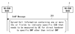
- FIG. 3 is a sequence diagram illustrating an example of signaling between RAN nodes according to the embodiment.
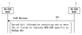
- FIG. 3 is a sequence diagram illustrating an example of signaling between RAN nodes according to the embodiment.
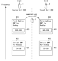
- FIG. 2 is a conceptual diagram of handover according to the embodiment. It is a flowchart which shows an example of operation of the RAN node concerning an embodiment. It is a flowchart which shows an example of operation of the RAN node concerning an embodiment.
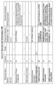
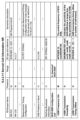
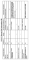
- FIG. 3 is a diagram illustrating an example of a format of a Served Cell Information NR information element according to an embodiment.
- FIG. 3 is a diagram illustrating an example of a format of a Served Cell Information NR information element according to an embodiment.
- FIG. 3 is a diagram illustrating an example of a format of a Served Cell Information NR information element according to an embodiment.
- FIG. 3 is a diagram illustrating an example of a format of a Served Cell Information NR information element according to an embodiment.
- FIG. 3 is a diagram illustrating an example of a format of a Served Cell Information NR information element according to an embodiment.
- FIG. 3 is a diagram illustrating an example of a format of a Served Cell Information NR information element according to an embodiment.
- FIG. 3 is a diagram illustrating an example of a format of a MeasurementTimingConfiguration message according to an embodiment.
- FIG. 3 is a diagram illustrating an example of a format of a MeasurementTimingConfiguration message according to an embodiment.
- FIG. 3 is a sequence diagram illustrating an example of signaling between RAN nodes according to the embodiment. It is a flowchart which shows an example of operation of the RAN node concerning an embodiment. It is a flowchart which shows an example of operation of the RAN node concerning an embodiment.
- FIG. 2 is a block diagram illustrating a configuration example of a RAN node according to an embodiment.
- LTE Long Term Evolution
- 5G system 5th generation mobile communication system
- if means “when,” “at or around the time,” and “after,” depending on the context. "after”, “upon”, “in response to determining", “in accordance with a determination", or “detecting” may be interpreted to mean “in response to detecting”. These expressions may be interpreted to have the same meaning, depending on the context.
- FIG. 1 shows a configuration example of a wireless communication system according to a plurality of embodiments.
- the wireless communication system includes NG-RAN node 1, NG-RAN node 2, and UE3.
- Each element (network function) shown in Figure 1 can be implemented, for example, as a network element on dedicated hardware, as a software instance running on dedicated hardware, or as an application platform. It can be implemented as an instantiated virtualization function.
- the NG-RAN node 1 is located in a Radio Access Network (RAN) (i.e., NG-RAN).
- RAN Radio Access Network
- NG-RAN node 1 may be gNB or ng-eNB.
- ng-eNB is a node that provides E-UTRA user plane and control plane protocol termination to the UE and is connected to the 5G Core Network (5GC) via the NG interface.
- the NG-RAN node 1 may be a Central Unit (CU) (e.g., gNB-CU or eNB-CU) in a cloud RAN (C-RAN) deployment, or may be a CU and one or more Distributed It may be a combination of Units (DUs) (e.g., gNB-DUs or eNB-DUs).
- DUs Units
- a C-RAN is also called CU/DU split.
- a CU may include a Control Plane (CP) Unit (e.g., gNB-CU-CP) and one or more User Plane (UP) Units (e.g., gNB-CU-UP).
- CP Control Plane
- UP User Plane
- the NG-RAN node 1 may be a CU-CP or a combination of a CU-CP and a CU-UP.
- the NG-RAN node 2 may be a CU or a combination of a CU and one or more DUs.
- the NG-RAN node 2 may be a CU-CP or a combination of a CU-CP and a CU-UP.
- NG-RAN nodes 1 and 2 communicate with each other via an inter-node interface (i.e., Xn interface) 101.
- the Xn interface 101 includes an Xn control plane (Xn-C) interface and an Xn user plane (Xn-U) interface.
- NG-RAN nodes 1 and 2 support Xn Application Protocol (XnAP) for signaling procedures on the Xn-C interface.
- XnAP Xn Application Protocol
- the transport network layer of the Xn-U interface is built on the Internet Protocol (IP) transport and overlays the General User Datagram Protocol (UDP)/IP to transport user plane Protocol Data Units (PDUs). Packet Radio Service Tunnelling Protocol User (GTP-U) is used.
- IP Internet Protocol
- UDP General User Datagram Protocol
- PDUs Packet Radio Service Tunnelling Protocol User
- the UE 3 is connected to the NG-RAN node 1 via the air interface 102.
- UE3 may perform carrier aggregation (CA). Specifically, the UE 3 may connect to multiple serving cells provided by the NG-RAN node 1 simultaneously.
- the plurality of serving cells include a primary cell (PCell) and one or more secondary cells (Secondary Cells (SCells)).
- UE3 may communicate with NG-RAN node 1 using CA between a PCell and one or more SCells.
- the UE 3 may be simultaneously connected to multiple NG-RAN nodes (i.e., Master Node (MN) and Secondary Node (SN)) for dual connectivity.
- the NG-RAN node 1 in FIG. 1 may be an MN (or M-NG-RAN node) or an SN (or S-NG-RAN node).
- MCG Master Cell Group
- An MCG is a group of serving cells associated with (or provided with) a MN, including a Special Cell (SpCell) (i.e., PCell) and optionally one or more SCells.
- SpCell Special Cell
- the NG-RAN node 1 when operating as an SN, provides a Secondary Cell Group (SCG) to the UE3.
- the SCG includes a Primary SCG Cell (PSCell) and optionally one or more SCells.
- PSCell is a Special Cell (SpCell) of SCG and supports Physical Uplink Control Channel (PUCCH) transmission and contention-based Random Access.
- PUCCH Physical Uplink Control Channel
- the NG-RAN node 2 may provide CA for the UE3 and may act as the MN or SN of the DC for the UE3.
- the UE3 may be a RedCap UE. If the UE3 is a RedCap UE, the UE3 may not support the CA and DC described above.
- UE3 supports handover from NG-RAN node 1 to NG-RAN node 2. If UE3 supports DC, the handover can be inter-MN handover, Master Node to gNB Change, or gNB to Master Node Change. It may be. The handover may be a conditional handover. Handover can also be referred to as network-controlled (intercell) mobility of an RRC_CONNECTED UE.
- intercell network-controlled
- This embodiment provides improved signaling between NG-RAN nodes.
- the configuration example of the wireless communication system according to this embodiment may be the same as the example shown in FIG. 1.
- Figure 2 shows an example of RAN inter-node signaling.
- the NG-RAN node 2 sends a control message to the NG-RAN node 1 indicating the configuration information of the cell provided by the NG-RAN node 2.
- the control message may be an XnAP message.
- the XnAP message may be a message sent in any procedure (i.e., Global Procedures) that is not related to a specific UE. More specifically, the XnAP message may be sent in the Xn Setup procedure or the NG-RAN node Configuration Update procedure.
- the purpose of the Xn Setup procedure is for two NG-RAN nodes to exchange application-level configuration data necessary to properly interoperate over the Xn-C interface.
- the purpose of the NG-RAN node Configuration Update procedure is to update the application-level configuration data necessary for two NG-RAN nodes to interoperate properly over the Xn-C interface.
- the control message (XnAP message) in step 201 may be, for example and without limitation, an XN SETUP REQUEST, XN SETUP RESPONSE, NG-RAN NODE CONFIGURATION UPDATE, or NG-RAN NODE CONFIGURATION UPDATE ACKNOWLEDGE message.
- the cell configuration information included in the control message in step 201 may include a Served Cell Information NR information element (IE).
- the Served Cell Information NR IE contains the cell configuration information of the NR cell that the neighboring NG-RAN node 1 may need for the XnAP interface.
- the configuration information of a cell indicates the specific SSB associated with the cell that needs to be measured by the UE for direct handover to a specific BWP of the cell that is different from the initial BWP of the cell. one or more information elements or fields.
- the configuration information for a cell includes a specific SSB associated with the cell that needs to be measured by the UE for direct handover to a specific BWP of the cell that is different from the initial BWP of the cell.
- the configuration information of a cell determines which of the associated SSBs configured in the cell is a unique SSB (or NCD-SSB) for direct handover to a BWP different from the initial BWP. Contains one or more information elements or fields for indicating.
- the configuration information of a cell may include one for indicating whether a specific SSB (or NCD-SSB) for direct handover to a BWP different from the initial BWP is configured or associated with the cell. or more information elements or fields.
- the cell configuration information may be one or more to indicate that a specific SSB (or NCD-SSB) for direct handover to a BWP different from the initial BWP is configured or available in the cell. Contains more information elements or fields.
- the initial BWP is associated with CD-SSB.
- the SSB consists of a PSS and SSS each occupying 1 symbol and 127 subcarriers, and a PBCH spanning 3 OFDM symbols and 240 subcarriers.
- CD-SSB is an SSB with associated RMSI.
- CD-SSB is an SSB with which SIB1 is associated.
- the CD-SSB is always located in the synchronization raster.
- a synchronous raster is also called an SS raster or an SSB raster. The synchronous raster occupies a predetermined (or fixed) part of the frequency range within the NR channel bandwidth.
- the initial BWP includes at least the DL BWP and may also include the UL BWP (if the serving cell is configured for uplink).
- a control resource set for Common Search Space i.e., Type0-PDCCH common search space
- the initial BWP is the BWP that the UE stays in first when accessing the serving cell (i.e., when transitioning from RRC_IDLE to RRC_CONNECTED).
- the unique SSB that needs to be measured by the UE for direct handover to a unique BWP of a cell that is different from the initial BWP of the cell is associated with the unique BWP that is different from the initial BWP.
- a unique BWP that is different from the initial BWP and can be a target BWP for direct handover is associated with a unique SSB that is different from the CD-SSB. That is, this unique SSB is NCD-SSB.
- Distinctive BWPs are not associated with CD-SSB, but are associated with NCD-SSB.
- a unique BWP is associated with (NCD-)SSB but not with RMSI (or SIB1). NCD-SSB and specific BWP may be located outside the synchronization raster.
- the above-mentioned specific BWP and specific SSB for direct handover to non-initial BWP may be the specific BWP and SSB for RedCap UEs.
- a BWP specific to RedCap UEs may be referred to as a RedCap specific BWP or a BWP for RedCap.
- RedCap-specific BWPs may be used for RedCap UEs as active BWPs, typically First Active BWPs.
- First active BWP is the BWP that the UE should use from the time (or immediately after) the establishment of a radio connection (RRC Connection Setup) is completed in a certain serving cell, or the BWP that the UE should use when the serving cell (e.g., SCell) is activated.
- the First Active BWP is designated to the UE in dedicated RRC signaling by the NG-RAN node.
- a RedCap UEs specific SSB may be referred to as a RedCap specific SSB, a RedCap specific NCD-SSB, an SSB for RedCap, or an NCD-SSB for RedCap.
- FIG. 3 shows a modification of the RAN inter-node signaling shown in FIG. 2.
- Step 301 is similar to step 201 in FIG. Specifically, in step 301, the NG-RAN node 2 sends a control message to the NG-RAN node 1 indicating cell configuration information provided by the NG-RAN node 2.
- the configuration information (e.g., Served Cell Information NR IE) of the cell includes one or more IEs or fields indicating NCD-SSB specific to RedCap UEs.
- the configuration information for the cell includes one or more IEs or fields indicating the location of the NCD-SSB specific to RedCap UEs.
- the configuration information of a cell includes one or more information elements or fields for indicating which of the plurality of SSBs configured or associated with the cell is a RedCap-specific NCD-SSB.
- the cell configuration information includes one or more information elements or fields to indicate whether a RedCap-specific SSB is configured or associated with the cell.
- the cell configuration information includes one or more information elements or fields to indicate that RedCap-specific SSB is configured or available in the cell.
- FIG. 4 conceptually illustrates a handover 400 from a source cell 420 to a target cell 460.
- the source cell is provided by NG-RAN node 1 and the target cell is provided by NG-RAN node 2.
- an initial BWP 422 for RedCap and a First Active BWP 424 for RedCap are set.
- Initial BWP422 includes CD-SSB421.
- First Active BWP424 includes NCD-SSB423.
- an initial BWP 462 for RedCap and a First Active BWP 464 for RedCap are set.
- Initial BWP462 includes CD-SSB461.
- First Active BWP464 includes NCD-SSB463.
- the UE 3 moves directly to the RedCap-specific BWP 464 of the target cell 460 containing the NCD-SSB 463 instead of to the initial BWP 462 of the target cell 460 containing the CD-SSB 461.
- the UE3 measures the NCD-SSB 463 in the First Active BWP 464 for RedCap of the target cell 460 while using the First Active BWP 424.
- the source NG-RAN node 1 generates and provides a measurement object to the UE 3 so that the UE 3 can measure the NCD-SSB 463 of the target cell 460.
- the source NG-RAN node 1 can generate a measurement object using the configuration information (e.g., Served Cell Information NR IE) of the target cell 460 provided by the target NG-RAN node 2.
- the configuration information (e.g., Served Cell Information NR IE) of the target cell 460 may be provided to the source NG-RAN node 1 via the control message in step 201 of FIG. 2 or step 301 of FIG.
- the measurement object for enabling the UE3 to measure the NCD-SSB 463 of the target cell 460 is a measurement object of the serving cell specific to the UE3 that is RRC_CONNECTED.
- the NG-RAN node 1 provides measurement settings to the RRC_CONNECTED UE 3 in the source cell 420, thereby configuring the UE 3 to perform measurements.
- a measurement configuration includes a list of one or more measurement objects, a list of one or more reporting configurations, and a list of one or more measurement identities.
- Each measurement object (MeasObject) is an object on which the UE 3 has to perform measurements.
- Each measurement object may indicate the frequency and timing location of reference signals to be measured, as well as subcarrier spacing.
- Each measurement object is identified by a measurement object identifier (MeasObjectId).
- Each reporting configuration may define reporting criteria, reference signal types, and reporting formats.
- Each report configuration is identified by a report configuration identifier (ReportConfigId).
- Each measurement identifier (MeasId) links one measurement object to one reporting configuration.
- the NG-RAN node 1 creates a measurement object for measuring the NCD-SSB 463 of the target cell 460 using the configuration information (e.g., Served Cell Information NR IE) of the target cell 460 provided by the target NG-RAN node 2. can be generated.
- the NG-RAN node 1 can then include the measurement object in the measurement configuration provided to the UE 3.
- the NG-RAN node 1 may include the reporting configuration associated with the measurement object in the measurement configuration of the UE 3.
- the NG-RAN node 1 can cause the RRC_CONNECTED UE 3 to measure the NCD-SSB 463 of the target cell 460 in the source cell 420, and can receive a report regarding the measurement from the UE 3. Based on this report, the NG-RAN node 1 can decide and initiate a handover 400 to hand over the UE 3 directly to the RedCap-specific BWP 464 of the target cell 460.
- BWPs shown in FIG. 4 are merely examples, and can be changed as appropriate.
- the initial BWP for RedCap in both the source cell 420 and the target cell 460, the initial BWP for RedCap is set to be linked to CD-SSB, and the First Active BWP for RedCap is set to be linked to NCD-SSB. It shows that it will be done.
- the initial BWP for RedCap may also be set in association with the NCD-SSB.
- FIG. 5 shows an example of the operation of the NG-RAN node 1.
- the second RAN node described in FIG. 5 means NG-RAN node 2.
- the NG-RAN node 1 receives a control message from the NG-RAN node 2 indicating cell configuration information provided by the NG-RAN node 2.
- the NG-RAN node 1 determines the unique SSB associated with the cell that needs to be measured by the UEs for direct handover to a unique BWP of the cell that is different from the initial BWP of the cell. , based on the received configuration information.
- NG-RAN node 1 determines the location of the distinctive SSB associated with the cell that needs to be measured by the UEs for direct handover to the distinctive BWP of the cell that is different from the initial BWP of the cell. is recognized based on the received configuration information. In other words, NG-RAN node 1 determines which of the multiple SSBs configured or associated with the cell served by NG-RAN node 2 is unique for direct handover to a BWP different from the initial BWP. It recognizes whether it is SSB (or NCD-SSB) based on the received configuration information.
- NG-RAN Node 1 is configured with or associated with a cell provided by NG-RAN Node 2 with a unique SSB (or NCD-SSB) for direct handover to a BWP different from the initial BWP. based on the received configuration information.
- NG-RAN Node 1 is configured or available in a cell where a unique SSB (or NCD-SSB) for direct handover to a BWP different from the initial BWP is provided by NG-RAN Node 2. based on the received configuration information.
- FIG. 6 shows a modification of the operation shown in FIG. Step 601 is similar to 501 in FIG.
- the NG-RAN node 1 receives from the NG-RAN node 2 a control message indicating cell configuration information provided by the NG-RAN node 2.
- the NG-RAN node 1 recognizes the NCD-SSB specific to the RedCap UEs associated with the cell provided by the NG-RAN node 2 based on the received configuration information.
- the NG-RAN node 1 recognizes the location of NCD-SSBs specific to RedCap UEs associated with the cell provided by the NG-RAN node 2 based on the received configuration information.
- the NG-RAN node 1 determines which of the multiple SSBs configured or associated with the cell provided by the NG-RAN node 2 is a RedCap-specific NCD-SSB based on the received configuration information. Recognize based on. Alternatively, the NG-RAN node 1 recognizes whether a RedCap-specific SSB is configured or associated with the cell provided by the NG-RAN node 2 based on the received configuration information. Alternatively, the NG-RAN node 1 recognizes that RedCap-specific SSB is configured or available in the cell provided by the NG-RAN node 2 based on the received configuration information.
- the Cell Configuration Information may contain one or more cells for direct handover to a non-initial BWP or for indicating the location of a specific NCD-SSB for RedCap UEs. information elements or fields.
- the location of a specific NCD-SSB includes the frequency location and time location of the radio resource on which the SSB is transmitted.
- specific NCD-SSBs may be configured in one cell for direct handover to non-initial BWPs or for RedCap UEs.
- the cell configuration information (e.g., Served Cell Information NR IE) may include one or more information elements or fields indicating the location of each of the plurality of unique NCD-SSBs.
- NG-RAN Node 1 provides a measurement object to UE3 that is RRC_CONNECTED in the cell of NG-RAN Node 1 and provides UE3 with a measurement object provided by NG-RAN Node 2.
- the NCD-SSB of the cell may be measured.
- the NG-RAN node 1 may assist a direct handover of the UE 3 to a BWP of a neighboring cell that is not associated with a CD-SSB but is associated with an NCD-SSB.
- the NG-RAN node 1 may assist the UE 3 in direct handover to a RedCap-specific BWP (e.g., RedCap-specific First Active BWP) associated with a RedCap-specific NCD-SSB in a neighboring cell.
- a RedCap-specific BWP e.g., RedCap-specific First Active BWP
- the cell configuration information indicates whether a specific NCD-SSB is configured or associated with the cell for direct handover to a non-initial BWP or for RedCap UEs.
- the cell configuration information is one or more information elements for indicating that a specific NCD-SSB is configured or available for direct handover to a non-initial BWP or for RedCap UEs.
- it may include a field.
- These one or more information elements or fields may be used by NG-RAN node 1 to know that a specific NCD-SSB is configured or available in the cell of neighboring NG-RAN node 2 .
- the NG-RAN node 1 determines that a specific NCD-SSB is configured in the cell of the adjacent NG-RAN node 2 based on the information element or field in the cell configuration information, the NG-RAN node 1 includes the specific NCD-SSB in the cell configuration information.
- a list of multiple measurement timing settings (e.g., MeasTiming) instances may be used to recognize the unique NCD-SSB location (e.g., frequency location and time location). For example, NG-RAN node 1 recognizes that a given instance (e.g., second instance, or last instance) in the list of MeasTiming instances is for a specific SSB for direct handover to RedCap or a non-initial BWP. You can.
- these one or more information elements or fields may be one or more XnAP information elements.
- these one or more information elements or fields may be included in the inter-node RRC message carried in the XnAP message.
- an inter-node RRC message is an RRC message sent between RAN nodes via an inter-node interface such as an Xn interface or an X2 interface.
- these one or more information elements or fields may include a list of multiple measurement timing settings (e.g., MeasTiming) instances. Each measurement timing configuration instance in the list indicates the frequency and timing occasion at which the corresponding SSB is measured. In one example, at least one of the measurement timing configuration instances included in the list may indicate that the SSB indicated in the instance is the above-mentioned unique SSB or NCD-SSB. In another example, the one or more information elements or fields further include an information element or field specifying which instance in the measurement timing settings list provides settings for the above-mentioned specific SSB or NCD-SSB. But that's fine.
- MeasTiming e.g., MeasTiming
- the Served Cell Information NR IE may be included in an XN SETUP REQUEST, XN SETUP RESPONSE, NG-RAN NODE CONFIGURATION UPDATE, or NG-RAN NODE CONFIGURATION UPDATE ACKNOWLEDGE message.
- Served Cell Information NR IE specifies the served cell in NR Physical Cell Identity (NR-PCI) IE and NR Cell Global Identity (CGI) IE.
- NR-PCI NR Physical Cell Identity
- CGI NR Cell Global Identity
- the Served Cell Information NR IE may optionally include the NCD-SSB Configuration IE.
- the Served Cell Information NR IE may optionally include the NCD-SSB Configuration List IE. That is, the NCD-SSB Configuration List IE in FIG. 8 can specify a plurality of NCD-SSBs up to a predetermined maximum number for one providing cell.
- the NCD-SSB Configuration IE and the NCD-SSB Configuration List IE indicate the NCD-SSB(s) of the cell specified by the Served Cell Information NR IE.
- the NCD-SSB Configuration IE and the NCD-SSB Configuration List IE include the SSB Frequency Info IE and may optionally include the SSB Transmission Periodicity IE and the SSB Transmission Timing Offset IE.
- SSB Frequency Info IE indicates the frequency position of NCD-SSB. Specifically, this indicates the center frequency of NCD-SSB.
- the SSB Transmission Periodicity IE and the SSB Transmission Timing Offset IE indicate the timing occasion when the SSB is transmitted. In other words, these IEs can be used to set timing opportunities for the UE to measure SSB.
- SSB Transmission Periodicity IE indicates the periodicity of the NCD-SSB.
- the SSB Transmission Periodicity IE is included in the Served Cell Information NR IE only when the periodicity of the relevant NCD-SSB is longer than the period of the CD-SSB. If SSB Transmission Periodicity IE is absent, this means that the periodicity of NCD-SSB is the same as that of CD-SSB.
- the SSB Transmission Timing Offset IE represents the offset of the SSB transmission timing in the number of half frames. If the SSB Transmission Timing Offset IE is absent, this means that the offset of the transmission timing of NCD-SSB is the same as that of CD-SSB.
- the Served Cell Information NR IE may optionally include the RedCap Measurement Timing Configuration IE.
- the RedCap Measurement Timing Configuration IE contains RedCap-specific MeasurementTimingConfiguration inter-node RRC messages.
- This MeasurementTimingConfiguration message contains a list of multiple MeasTiming instances. Each MeasTiming instance in the list indicates the frequency and timing occasion at which the corresponding SSB is measured. That is, the MeasurementTimingConfiguration message carried in the RedCap Measurement Timing Configuration IE provides measurement timing configuration only for one or more RedCap specific NCD-SSBs.
- the Served Cell Information NR IE may optionally include the NCD-SSB Transmission Indication IE.
- the IE indicates whether a specific NCD-SSB is configured or associated with the cell for direct handover to a non-initial BWP or for RedCap UEs.
- the IE indicates that a specific NCD-SSB is configured or available in the cell for direct handover to a BWP different from the initial BWP.
- the NCD-SSB Transmission Indication IE is of enumerated type and indicates "activated”.
- the NCD-SSB Transmission Indication IE may indicate “activated” or “deactivated”.
- the NG-RAN node 1 determines that a specific NCD-SSB is configured in the cell of the adjacent NG-RAN node 2 based on the NCD-SSB Transmission Indication IE in the Served Cell Information NR, the NG-RAN node 1 A list of multiple MeasTiming instances contained in the Information NR IE may be used to recognize the location (e.g., frequency location and time location) of a specific NCD-SSB.
- the Served Cell Information NR IE may optionally include the NCD-SSB Positions in Burst IE.
- the IE first indicates whether a specific NCD-SSB is configured or associated with the cell for direct handover to a non-initial BWP or for RedCap UEs.
- the IE indicates that a specific NCD-SSB is configured or available in the cell for direct handover to a BWP different from the initial BWP.
- the IE indicates the time domain position of NCD-SSB beams transmitted within one half-frame (i.e., one burst set).
- the NG-RAN node 1 determines that a specific NCD-SSB is configured in the cell of the adjacent NG-RAN node 2 based on the NCD-SSB Positions in Burst IE in the Served Cell Information NR, the NG-RAN node 1 A list of multiple MeasTiming instances contained in the Cell Information NR IE may be used to recognize the location of a specific NCD-SSB.
- the Served Cell Information NR IE may optionally include the NCD-SSB Positions in Burst List IE.
- the IE first indicates whether one or more NCD-SSBs specific for direct handover to non-initial BWPs or for RedCap UEs are configured or associated with the cell. .
- the IE indicates that one or more unique NCD-SSBs are configured or available in the cell for direct handover to a BWP different from the initial BWP.
- the IE specifies, for each NCD-SSB, NCD-SSB Positions in order to indicate the time-domain positions of the NCD-SSB beams transmitted within one half-frame (i.e., one burst set).
- the NCD-SSB Positions in Burst List IE includes the NR-PCI IE to indicate the PCI associated with each NCD-SSB. Further, the NCD-SSB Positions in Burst List IE may include an absoluteFrequencySSB IE to indicate the frequency position (e.g., center frequency) of each NCD-SSB.
- NG-RAN Node 1 determines that one or more unique NCD-SSBs are configured in the cells of neighboring NG-RAN Node 2 based on the NCD-SSB Positions in Burst List IE in the Served Cell Information NR. Once determined, the list of multiple MeasTiming instances contained in the Served Cell Information NR IE may be used to identify the location of one or more unique NCD-SSBs.
- Each of the NCD-SSB Configuration IE, NCD-SSB Configuration List IE, and RedCap Measurement Timing Configuration IE may include one or more IEs other than those illustrated.
- the NCD-SSB Configuration IE and the NCD-SSB Configuration List IE are used to indicate the time-domain positions of SSB beams transmitted within one half-frame (i.e., one burst set). May include In Burst IE.
- MeasTimingList (1301) defines a sequence of one or more MeasTiming instances.
- Each MeasTiming instance (1302) defines the information necessary for the UE to measure SSB.
- each MeasTiming instance (1302) indicates frequency allocation (i.e., center frequency), subcarrier spacing, and SSB Measurement Timing Configuration (SSB-MTC).
- the SSB-MTC defines the periodicity and offset of the SSB that is necessary for the UE to set up timing opportunities to measure the SSB.
- each MeasTiming instance (1302) can optionally include an ncd-SSB-RedCap field (1303).
- the ncd-SSB-RedCap field (1303) is of enumerated type and indicates "true”. If the MeasTiming instance (1302) includes the ncd-SSB-RedCap field (1303), it means that the SSB indicated by the instance is a RedCap-specific NCD-SSB.
- MeasTimingList (1401) defines a sequence of one or more MeasTiming instances.
- Each MeasTiming instance (1402) defines the information necessary for the UE to measure SSB.
- each MeasTiming instance (1402) indicates frequency allocation (i.e., center frequency), subcarrier spacing, and SSB-MTC.
- the campOnFirstSSB field (1403) is of Boolean type.
- the campOnFirstSSB field (1403) set to the value true indicates that the SSB listed or indicated in the first MeasTiming instance of the MeasTiming list (1401) can be used for camping and PCell configuration (i.e. in spCellConfigCommon of masterCellGroup) Display.
- the MeasurementTimingConfiguration message includes a HandoverOnSecondSSB-RedCap field (1404).
- the HandoverOnSecondSSB-RedCap field (1404) is of Boolean type.
- the HandoverOnSecondSSB-RedCap field (1404) set to the value true indicates that the SSB listed or indicated in the second MeasTiming instance of the MeasTiming list (1401) is a RedCap-specific NCD-SSB.
- the format of the inter-node RRC message described with reference to FIGS. 13 and 14 is an example and can be modified in various ways.
- the name of the ncd-SSB-RedCap field (1303) in FIG. 13 may be changed to something else, such as "ncd-SSB-supportHO" or "ncd-SSB-supportCampOn.”
- the name of the HandoverOnSecondSSB-RedCap field (1404) in FIG. 14 may be changed to something else, such as "HandoverOnSecondSSB” or "HandoverOnSecondSSB.”
- the inter-node RRC message format shown in or similar to FIG. 13 or 14 may be used in conjunction with the new Xn information element in any of FIGS. 10-12 or similar.
- NG-RAN Node 1 can know whether any of the SSBs in the cell provided by NG-RAN Node 2 are unique NCD-SSBs for direct handover to a BWP different from the initial BWP. . In other words, NG-RAN node 1 cannot know whether a specific NCD-SSB for direct handover to a BWP different from the initial BWP is configured in the cell served by NG-RAN node 2. can. In other words, NG-RAN Node 1 determines the unique NCD-SSB location for direct handover to a BWP different from the initial BWP associated with the cell served by NG-RAN Node 2. can be known.
- NG-RAN node 1 may know which of the SSBs in the cell provided by NG-RAN node 2 are specific to RedCap UE. In other words, the NG-RAN node 1 can know whether the SSB specific to RedCap UEs is configured in the cell provided by the NG-RAN node 2. In other words, NG-RAN Node 1 may know the location of the SSB specific to RedCap UEs associated with the cell served by NG-RAN Node 2.
- NG-RAN Node 1 may determine that a specific NCD-SSB is configured or available in the cell served by NG-RAN Node 2 for direct handover to a BWP different from the initial BWP. You can know. Alternatively, the NG-RAN node 1 may know that RedCap-specific NCD-SSB is configured or available in the cell provided by the NG-RAN node 2.
- This embodiment provides improvements in the operation of an NG-RAN node when receiving control messages from other NG-RAN nodes.
- the configuration example of the wireless communication system according to this embodiment may be the same as the example shown in FIG. 1.
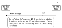
- FIG. 15 shows an example of RAN inter-node signaling.
- the NG-RAN node 2 sends an XnAP message to the NG-RAN node 1 that includes the cell configuration information (i.e., Served Cell Information NR IE) provided by the NG-RAN node 2 .
- the XnAP message may be, for example and without limitation, an XN SETUP REQUEST, XN SETUP RESPONSE, NG-RAN NODE CONFIGURATION UPDATE, or NG-RAN NODE CONFIGURATION UPDATE ACKNOWLEDGE message.
- the Served Cell Information NR IE includes the RedCap Broadcast Information IE and the Measurement Timing Configuration IE.
- the RedCap Broadcast Information IE and Measurement Timing Configuration IE may be similar to those included in the existing Served Cell Information NR IE.
- the Measurement Timing Configuration IE shows a list of MeasTiming instances.
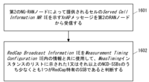
- FIG. 16 shows an example of the operation of the NG-RAN node 1.
- the second RAN node described in FIG. 16 means NG-RAN node 2.
- the NG-RAN node 1 receives an XnAP message from the NG-RAN node 2 indicating the Served Cell Information NR IE of the cell provided by the NG-RAN node 2.
- the Served Cell Information NR IE includes the RedCap Broadcast Information IE and the Measurement Timing Configuration IE.
- NG-RAN Node 1 uses the RedCap Broadcast Information IE in conjunction with the information in the Measurement Timing Configuration IE to determine whether at least one of the one or more NCD-SSBs indicated in the list of MeasTiming instances is RedCap It is determined that this is a unique SSB. In other words, using the RedCap Broadcast Information IE along with the information in the Measurement Timing Configuration IE, NG-RAN Node 1 determines the RedCap-specific SSB (or NCD-SSB) configured in the cell served by NG-RAN Node 2. ) is implicitly known.
- NG-RAN Node 1 determines that a given instance (e.g., second instance, or last instance) in the list of MeasTiming instances is RedCap-specific. It may be recognized that it is related to SSB.
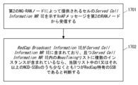
- FIG. 17 shows another example of the operation of the NG-RAN node 1.
- Step 1701 is similar to step 1601 in FIG.
- the NG-RAN node 1 determines that the RedCap Broadcast Information IE is included in the Served Cell Information NR IE, and that the MeasTiming list in the Served Cell Information NR IE includes multiple instances, or To detect.
- the NG-RAN node 1 determines that at least one of the one or more NCD-SSBs in the list is a RedCap-specific SSB.
- the NG-RAN node 1 implicitly knows the RedCap-specific SSB (or NCD-SSB) configured in the cell provided by the NG-RAN node 2.
- NG-RAN Node 1 determines that a given instance (e.g., second instance, or last instance) in the list of MeasTiming instances is RedCap-specific. It may be recognized that it is related to SSB.
- the NG-RAN node 1 determines RedCap UEs-specific information in the cell provided by the NG-RAN node 2 based on the information contained in the existing Served Cell Information NR IE. You can check whether SSB is set or not.
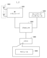
- FIG. 18 is a block diagram showing a configuration example of the NG-RAN node 1 according to the above embodiment.
- the NG-RAN node 2 may also have a configuration similar to that shown in FIG. 18.
- the NG-RAN node 1 includes a Radio Frequency (RF) transceiver 1801, a network interface 1803, a processor 1804, and a memory 1805.
- RF transceiver 1801 performs analog RF signal processing to communicate with UEs.
- RF transceiver 1801 may include multiple transceivers.
- RF transceiver 1801 is coupled to antenna array 1802 and processor 1804.
- RF transceiver 1801 receives modulation symbol data from processor 1804, generates a transmit RF signal, and provides the transmit RF signal to antenna array 1802.
- RF transceiver 1801 generates a baseband reception signal based on the reception RF signal received by antenna array 1802 and supplies this to processor 1804.
- RF transceiver 1801 may include analog beamformer circuitry for beamforming.
- the analog beamformer circuit includes, for example, multiple phase shifters and multiple power amplifiers.
- the network interface 1803 is used to communicate with network nodes (e.g. other RAN nodes, as well as control plane nodes and user plane nodes of the core network).
- the network interface 1803 may include, for example, a network interface card (NIC) compliant with the IEEE 802.3 series.
- NIC network interface card
- the processor 1804 performs digital baseband signal processing (data plane processing) and control plane processing for wireless communication.
- Processor 1804 may include multiple processors.
- the processor 1804 includes a modem processor (e.g., Digital Signal Processor (DSP)) that performs digital baseband signal processing, and a protocol stack processor (e.g., Central Processing Unit (CPU) or Micro Processing Unit (CPU)) that performs control plane processing. MPU)).
- DSP Digital Signal Processor
- MPU Micro Processing Unit
- digital baseband signal processing by processor 1804 includes the Service Data Adaptation Protocol (SDAP) layer, the Packet Data Convergence Protocol (PDCP) layer, the Radio Link Control (RLC) layer, the Medium Access Control (MAC) layer, and the Physical (PHY) layer. ) layer signal processing.
- SDAP Service Data Adaptation Protocol
- PDCP Packet Data Convergence Protocol
- RLC Radio Link Control
- MAC Medium Access Control
- PHY Physical
- control plane processing by the processor 1804 may include processing of Non-Access Stratum (NAS) messages, RRC messages, Medium Access Control (MAC) Control Elements (CEs), and Downlink Control Information (DCI).
- Control plane processing by processor 1804 may also include processing of application layer signaling protocols such as XnAP, F1AP, NGAP, etc.
- Processor 1804 may include a digital beamformer module for beamforming.
- the digital beamformer module may include a Multiple Input Multiple Output (MIMO) encoder and precoder.
- MIMO Multiple Input Multiple Output
- the memory 1805 is configured by a combination of volatile memory and nonvolatile memory.
- Volatile memory is, for example, Static Random Access Memory (SRAM) or Dynamic RAM (DRAM) or a combination thereof.
- Non-volatile memory is masked Read Only Memory (MROM), Electrically Erasable Programmable ROM (EEPROM), flash memory, or a hard disk drive, or any combination thereof.
- Memory 1805 may include storage located remotely from processor 1804. In this case, processor 1804 may access memory 1805 via network interface 1803 or I/O interface.
- the memory 1805 may store one or more software modules (computer programs) 1806 containing instructions and data for processing by the NG-RAN node 1 described in the embodiments above.
- the processor 1804 may be configured to read and execute the software module 1806 from the memory 1805 to perform the processing of the NG-RAN node 1 described in the embodiments above.
- NG-RAN node 1 is a Central Unit (CU) (e.g. eNB-CU or gNB-CU) or CU-CP, NG-RAN node 1 does not include RF transceiver 1801 (and antenna array 1802). You can.
- CU Central Unit
- eNB-CU or gNB-CU e.g. gNB-CU
- CU-CP e.g. gNB-CP
- NG-RAN node 1 does not include RF transceiver 1801 (and antenna array 1802). You can.
- each of the processors included in the NG-RAN nodes 1 and 2 includes a set of instructions for causing a computer to execute the algorithm explained using the drawings. Or multiple programs can be executed.
- the program includes instructions (or software code) that, when loaded into a computer, cause the computer to perform one or more of the functions described in the embodiments.
- the program may be stored on a non-transitory computer readable medium or a tangible storage medium.
- computer readable or tangible storage media may include random-access memory (RAM), read-only memory (ROM), flash memory, solid-state drive (SSD) or other memory technology, CD - Including ROM, digital versatile disk (DVD), Blu-ray disk or other optical disk storage, magnetic cassette, magnetic tape, magnetic disk storage or other magnetic storage device.
- the program may be transmitted on a transitory computer-readable medium or a communication medium.
- transitory computer-readable or communication media includes electrical, optical, acoustic, or other forms of propagating signals.
- a first radio access network (RAN) node the first radio access network (RAN) node comprising: at least one memory; at least one processor coupled to the at least one memory; Equipped with The at least one processor includes: receiving a control message from the second RAN node indicating cell configuration information provided by the second RAN node; A unique Synchronization Signal (SS)/Physical Broadcast Channel associated with said cell that needs to be measured by the User Equipment (UE) for direct handover to a unique BWP of said cell that is different from the initial BWP of said cell. (PBCH) block (SSB) based on the configuration information, configured like this, First RAN node.
- SS Synchronization Signal
- UE User Equipment
- the configuration information includes one or more information elements or fields for indicating the location of the specific SSB;
- the unique SSB includes a plurality of unique SSBs; the one or more information elements or fields indicating the location of each of the plurality of unique SSBs;
- the one or more information elements or fields are used by the first RAN node to configure the UE with a timing opportunity to measure the specific SSB;
- the first RAN node according to appendix 2 or 3.
- the at least one processor is configured to recognize the location of the unique SSB based on the configuration information; The first RAN node according to any one of Supplementary Notes 1 to 4.
- the control message is an Xn Application Protocol (XnAP) message, the one or more information elements or fields are one or more XnAP information elements; The first RAN node according to any one of Supplementary Notes 2 to 5.
- the control message is an Xn Application Protocol (XnAP) message, the one or more information elements or fields are included in an inter-node Radio Resource Control (RRC) message carried in the control message; The first RAN node according to any one of Supplementary Notes 2 to 5.
- RRC Radio Resource Control
- the one or more information elements or fields include a list of multiple MeasTiming instances; Each MeasTiming instance in said list indicates the frequency and timing occasion at which the corresponding SSB is measured; at least one MeasTiming instance included in said list indicates that the SSB indicated in said instance is said unique SSB;
- the first RAN node described in Appendix 7. the one or more information elements or fields include a list of multiple MeasTiming instances; Each MeasTiming instance in said list indicates the frequency and timing occasion at which the corresponding SSB is measured;
- the one or more information elements or fields further include an information element or field specifying which MeasTiming instance of the list provides configuration for the specific SSB.
- the first RAN node described in Appendix 7. The configuration information includes one or more information elements or fields indicating whether the specific SSB is associated with or configured with the cell; The first RAN node described in Appendix 1.
- the control message is an Xn Application Protocol (XnAP) message, the one or more information elements or fields are one or more XnAP information elements;
- XnAP Xn Application Protocol
- the at least one processor is configured to recognize whether the specific SSB is associated with or configured with the cell based on the configuration information;
- the control message is an Xn Application Protocol (XnAP) message
- the configuration information includes a Served Cell Information NR information element,
- the Served Cell Information NR information element includes a RedCap Broadcast Information information element and a Measurement Timing Configuration information element,
- the Measurement Timing Configuration information element includes a list of one or more MeasTiming instances;
- the at least one processor uses the RedCap Broadcast Information information element in conjunction with information in the Measurement Timing Configuration information element to determine at least one of the one or more Non-Cell Defining (NCD) SSBs indicated in the list. configured to determine that one is the unique SSB;
- NCD Non-Cell Defining
- the control message is an Xn Application Protocol (XnAP) message
- the configuration information includes a Served Cell Information NR information element,
- the Served Cell Information NR information element includes a Measurement Timing Configuration information element,
- the Measurement Timing Configuration information element includes a list of one or more MeasTiming instances; each MeasTiming instance in said list indicates the frequency and timing occasion at which the corresponding SSB is measured; If a RedCap Broadcast Information information element is included in the Served Cell Information NR information element and a plurality of MeasTiming instances are included in the list, the at least one processor configured to determine that at least one of the Non-Cell Defining (NCD) SSBs is the unique SSB; The first RAN node described in Appendix 1.
- NCD Non-Cell Defining
- the location of the unique SSB includes a frequency location and a time location of a radio resource on which the unique SSB is transmitted.
- the first RAN node according to any one of Supplementary Notes 2 to 5.
- the unique SSB is a Non-Cell Defining (NCD) SSB with no associated RMSI or SIB1;
- the first RAN node according to any one of Supplementary Notes 1 to 15.
- the initial BWP is a BWP associated with a Cell Defining (CD) SSB associated with Remaining Minimum System Information (RMSI) or System Information Block Type 1 (SIB1), The first RAN node according to Appendix 16.
- CD Cell Defining
- RMSI Remaining Minimum System Information
- SIB1 System Information Block Type 1
- the CD-SSB is arranged in a predetermined synchronous raster; the NCD-SSB is not located on the synchronous raster; The first RAN node according to Appendix 17.
- the frequency position of the unique SSB is not included in the initial BWP and is included in the unique BWP; The first RAN node according to any one of Supplementary Notes 1 to 18.
- the specific SSB is a SSB specific to Reduced Capability (RedCap) UEs; The first RAN node according to any one of Supplementary Notes 1 to 19.
- a method performed by a first radio access network (RAN) node comprising: receiving from said second RAN node a control message indicating configuration information of a cell provided by a second RAN node; and for direct handover to a specific BWP of said cell different from an initial BWP of said cell.
- RAN radio access network
- SS Synchronization Signal
- PBCH Physical Broadcast Channel
- a program for causing a computer to perform a method for a first radio access network (RAN) node comprising: The method includes: receiving from said second RAN node a control message indicating configuration information of a cell provided by a second RAN node; and for direct handover to a specific BWP of said cell different from an initial BWP of said cell.
- RAN radio access network
- SS Synchronization Signal
- PBCH Physical Broadcast Channel
- SSB Physical Broadcast Channel
- a second radio access network (RAN) node comprising: at least one memory; at least one processor coupled to the at least one memory; Equipped with The at least one processor includes: configured to send a control message to the first RAN node indicating cell configuration information provided by the second RAN node;
- the configuration information includes a specific Synchronization Signal (SS )/Physical Broadcast Channel (PBCH) block (SSB); Second RAN node.
- SS Synchronization Signal
- PBCH Physical Broadcast Channel
- Second RAN node Second RAN node.
- the unique SSB includes a plurality of unique SSBs; the one or more information elements or fields indicating the location of each of the plurality of unique SSBs; The second RAN node according to Appendix 24.
- the one or more information elements or fields are used by the first RAN node to configure the UE with a timing opportunity to measure the specific SSB;
- the second RAN node according to any one of Supplementary Notes 23 to 25.
- the one or more information elements or fields are used by the first RAN node to recognize the location of the specific SSB;
- the second RAN node according to any one of Supplementary Notes 23 to 25.
- the control message is an Xn Application Protocol (XnAP) message, the one or more information elements or fields are one or more XnAP information elements; The second RAN node according to any one of Supplementary Notes 23 to 27.
- the control message is an Xn Application Protocol (XnAP) message, the one or more information elements or fields are included in an inter-node Radio Resource Control (RRC) message carried in the control message; The second RAN node according to any one of Supplementary Notes 23 to 28.
- RRC Radio Resource Control
- the one or more information elements or fields include a list of multiple MeasTiming instances; each MeasTiming instance in said list indicates the frequency and timing occasion at which the corresponding SSB is measured; at least one MeasTiming instance included in said list indicates that the SSB indicated in said instance is said unique SSB;
- the second RAN node according to Appendix 29.
- the one or more information elements or fields include a list of multiple MeasTiming instances; Each MeasTiming instance in said list indicates the frequency and timing occasion at which the corresponding SSB is measured; The one or more information elements or fields further include an information element or field specifying which MeasTiming instance of the list provides configuration for the specific SSB.
- the second RAN node according to Appendix 29.
- the location of the unique SSB includes a frequency location and a time location of a radio resource on which the unique SSB is transmitted.
- the second RAN node according to appendix 24, 25, or 27.
- (Appendix 33) the one or more information elements or fields indicate whether the specific SSB is associated with or configured with the cell;
- (Appendix 34) the one or more information elements or fields are used by the first RAN node to recognize whether the specific SSB is associated or configured with the cell;
- the control message is an Xn Application Protocol (XnAP) message, the one or more information elements or fields are one or more XnAP information elements;
- XnAP Xn Application Protocol
- the unique SSB is a Non-Cell Defining (NCD) SSB with no associated RMSI or SIB1; The second RAN node according to any one of Supplementary Notes 23 to 35.
- the initial BWP is a BWP associated with a Cell Defining (CD) SSB associated with Remaining Minimum System Information (RMSI) or System Information Block Type 1 (SIB1), The second RAN node according to Appendix 36.
- the CD-SSB is arranged in a predetermined synchronous raster; the NCD-SSB is not located on the synchronous raster; The second RAN node according to Appendix 37.
- the frequency position of the unique SSB is not included in the initial BWP and is included in the unique BWP;
- the second RAN node according to any one of Supplementary Notes 23 to 38.
- the specific SSB is a SSB specific to Reduced Capability (RedCap) UEs;
- the second RAN node according to any one of Supplementary Notes 23 to 39.
- a method performed by a second radio access network (RAN) node comprising: sending a control message to the first RAN node indicating cell configuration information provided by the second RAN node;
- the configuration information includes a specific Synchronization Signal (SS )/Physical Broadcast Channel (PBCH) block (SSB); Method.
- SS Synchronization Signal
- PBCH Physical Broadcast Channel
- a program for causing a computer to perform a method for a second radio access network (RAN) node comprising: The method comprises sending a control message to a first RAN node indicating configuration information for a cell provided by the second RAN node;
- the configuration information includes a specific Synchronization Signal (SS )/Physical Broadcast Channel (PBCH) block (SSB); program.
- SS Synchronization Signal
- PBCH Physical Broadcast Channel
Landscapes
- Engineering & Computer Science (AREA)
- Computer Networks & Wireless Communication (AREA)
- Signal Processing (AREA)
- Mobile Radio Communication Systems (AREA)
Abstract
第1のRANノード(1)は、第2のRANノード(2)によって提供されるセルの設定情報を示す制御メッセージ(201)を第2のRANノード(2)から受信する。第1のRANノード(1)は、当該セルのイニシャルBandwidth Part(BWP)とは異なる当該セルの特有のBWPへの直接ハンドオーバのためにUser Equipment(3)によって測定される必要がある当該セルに関連付けられた特有のSSBを、受信した設定情報に基づいて認識する。これは、例えば、他のRANノードによって提供されているセルの非イニシャルBWPへの直接ハンドオーバのために利用可能なNon-Cell Defining(NCD) SSBを知ることをRANノードに可能にすることに寄与できる。
Description
本開示は、無線通信システムに関し、特に無線アクセスネットワークノード間のシグナリングに関する。
3rd Generation Partnership Project (3GPP(登録商標)) Release 17は、Reduced Capability (RedCap) UEsをサポートする(例えば、非特許文献1のセクション16.13を参照)。RedCap UE は、低い複雑さ(complexity)を持つことを意図して、非 RedCap UE に比べて削減された機能を持つ。RedCap UEは、FR1(i.e., sub-6 GHz バンド)で20 MHz、FR2(i.e., millimeter wave (mmWave) バンド)で100 MHzの最大UEチャネル帯域幅をサポートすることが必須である。一方、Carrier Aggregation (CA)、Multi-Radio Dual Connectivity (MR-DC)、Dual Active Protocol Stack (DAPS)、及びIntegrated Access and Backhaul (IAB) 関連の機能は、RedCap UEsではサポートされない。
RedCap UEsは、例えば、UE受信(Reception (Rx))ブランチの最小数及びダウンリンク(Downlink (DL)) Multiple Input Multiple Output (MIMO) レイヤの最大数が非RedCap UEsのそれらに比べて減少又は緩和される。FR1では、1つのRxブランチがサポートされている場合は1つのDL MIMOレイヤが、2つのRxブランチがサポートされている場合は2つのDL MIMOレイヤがサポートされる。FR2では、1又は2つのDL MIMOレイヤがサポート可能であり、2つのRxブランチは常にサポートされる。FR1及びFR2では、2つを超えるUE Rxブランチ又は2つを超えるDL MIMO レイヤに関連するUE機能および対応する能力、並びに2つを超えるUE Txブランチ又は2つを超えるアップリンク(Uplink (UL)) MIMOレイヤに関連するUE機能および能力は、RedCap UEsによりサポートされない。
Radio Resource Control (RRC)_IDLE及びRRC_INACTIVEのRedCap UEは、Cell Defining (CD) Synchronization Signal (SS)/Physical Broadcast Channel (PBCH) block (SSB)に関連付けられたイニシャルBandwidth Part (BWP)(デフォルトまたは RedCap特有)においてのみページングをモニターし、CD-SSBでセルの(再)選択及び測定を実行する。RedCap特有のイニシャルUL BWPが設定された場合、RRC_IDLE及びRRC_INACTIVEのRedCap UEsは、ランダムアクセス(Random Access Channel (RACH))を実行するためにRedCap特有のイニシャルUL BWPのみを使用する必要がある。
RedCap UEは、各BWPが最大1つまでのSSBを設定されることを条件として、複数のNon-Cell Defining (NCD) SSBsを設定されることがある。RRC_CONNECTEDでは、アクティブBWPがCD-SSBを包含していない場合、Radio Link Monitoring (RLM)、Beam Failure Detection (BFD)、及びサービングセル測定を実行するために、RedCap UEに対してNCD-SSBが設定されてもよい。
なお、SSBは、各々が1シンボル及び127サブキャリアを占有するprimary and secondary synchronization signals (PSS, SSS)と、3 Orthogonal Frequency Division Multiplexing (OFDM) シンボル及び240サブキャリアにまたがるPhysical Broadcast Channel (PBCH) で構成される。CD-SSBは、Remaining Minimum System Information (RMSI) が関連付けられたSSBである。言い換えると、CD-SSBは、System Information Block Type 1 (SIB1) が関連付けられたSSBである。RRC_IDLE又はRRC_INACTIVEでのセル選択及びセル再選択のためにUEsがサーチするべき周波数範囲を限定するために、CD-SSBは、常に同期ラスター(synchronization raster)に位置する。同期ラスターは、SSラスター又はSSBラスターとも呼ばれる。同期ラスターは、NRチャネル帯域(Bandwidth)内で、予め定められた(又は固定された)一部の周波数範囲を占有する。
以下の幾つかの段落は、非特許文献2に記載された、RedCap UEs向けのNCD-SSBの課題に関する回答を示している。RedCap UEのアクティブBWPがNCD-SSBと関連付けられている場合、NCD-SSB又はCD-SSBのいずれでサービングセル測定を実行するかはネットワーク次第である。BWPがNCD-SSBと関連付けられている場合、BWP特有の(BWP-specific)サービングセル測定オブジェクト、すなわちBWP-DownlinkDedicatedの下に定義されるservingCellMO、を設定することができる。RedCap UEは、それがアクティブBWPに設定されている場合、サービングセル測定にこのservingCellMOを使用し、それ以外の場合は、ServingCellConfigで定義されている現行の(legacy)servingCellMOを使用する。サービングセル測定用にCD-SSB及び/又は複数のNCD-SSBを設定することが可能であるが、UEはCD-SSB又はNCD-SSBのいずれかと関連付けられたアクティブBWPの設定済みサービングセル測定オブジェクトを用いて測定を行うものとする。
Technical Specification Group (TSG) Radio Access Network (RAN) Working Group 2 (RAN2) シグナリングの観点から、BWP-DownlinkDedicatedの下でBWP特有の(BWP-specific)servingCellMOを構成することができる。このservingCellMOで定義されたSSBは、UEがこのアクティブBWPにいるときにサービングセル測定に使用される参照(reference)SSBである。一方、このフィールドが存在しないなら、ServingCellConfigの下でservingCellMOにより定義されたSSBがサービングセル測定に使用される参照SSBである。この参照SSBは、周波数内測定(intra-frequency measurements)を定義するために使用される。
RAN2の観点からは、CD-SSBに関連するイニシャルBWPにではなく、NCD-SSBに関連付けられたターゲットセルの特定のRedcap BWPへの直接のハンドオーバがサポートされる。
非特許文献3及び4に記載されているように、3GPP TSG-RANは、NCD-SSBがRedCap UEsのためにサポートされることを合意している。加えて、これらの文献に記載されているように、非RedCap UEsに対するNCD-SSBの適用可能性が議論されている。将来的に、Rel-17 RedCap Work Item (WI)のNCD-SSBがRedCap UEsと非RedCap UEsを含むすべてのUEsに適用される可能性がある。
非特許文献5に記載されているように、Xn Setup手順又はNG-RAN node Configuration Update手順において、gNBは、他のgNBからServed Cell Information NR IEを含むXn Application Protocol (XnAP) メッセージを受信できる。これにより、gNBは、他のgNBの提供(served)セルで設定されている複数のSSBsに関する複数のMeasTimingのリストを知ることができ、このリストの最初のMeasTimingインスタンスに記載されたSSBがキャンピング及びPrimary Cell (PCell) 設定(すなわち、masterCellGroupのspCellConfigCommon内)のために使用できることを知ることができる。
3GPP TS 38.300 V17.1.0 (2022-06), 3rd Generation Partnership Project; Technical Specification Group Radio Access Network; NR; NR and NG-RAN Overall Description; Stage 2 (Release 17), 2022年7月
RAN2, "LS on NCD-SSB issues for RedCap UE (R4-2207104)", R2-2206662, 3GPP TSG-RAN WG2 Meeting #118-e, May 9-20, 2022
vivo, "Discussion on NCD-SSB for non-RedCap UEs", RP-221275, 3GPP TSG-RAN Meeting #96, June 6-9, 2022
Vodafone, "NCD-SSB for all devices: proposed Way Forward", RP-221870, 3GPP TSG-RAN Meeting #96, Budapest, Hungary, June 6-9, 2022
3GPP TS 38.423 V17.1.0 (2022-06), "3rd Generation Partnership Project; Technical Specification Group Radio Access Network; NG-RAN; Xn application protocol (XnAP) (Release 17)", 2022年6月
上述のように、3GPP Release 17は、ソースセルからターゲットセルへのRedCap UEsのハンドオーバに関して、RedCap UEsに特有であり且つNCD-SSBに関連付けられたBWPへの直接ハンドオーバをサポートする予定である。これを可能にするためには、ソースgNBは、ターゲットセルにおけるRedCap特有のNCD-SSBを、又はRedCap特有のNCD-SSBに関連付けられたRedCap特有のBWPを知っていることが好ましい。なぜなら、ソースRANノードは、ソースセルにおいてRRC_CONNECTEDのRedCap UEsに測定オブジェクトを生成して提供し、これらのRedCap UEsがターゲットセルのRedCap特有のBWP内のRedCap特有のNCD-SSBを測定できるようにする必要があるためである。
上述のように、現在のXnAPシグナリングの規定(例えば、非特許文献5を参照)では、gNBは、他のgNBの提供(served)セルで設定されている複数のSSBsに関する複数のMeasTimingのリストを知ることができ、このリストの最初のMeasTimingインスタンスに記載されたSSBがキャンピング及びPSCell設定(すなわち、masterCellGroupのspCellConfigCommon内)のために使用できることを知ることができる。言い換えると、gNBは、他のgNBにより提供されたMeasTimingリストの最初のインスタンスに記載されたSSBがCD-SSBであることを知ることができる。
しかしながら、現在のXnAPシグナリングの規定では、gNBは、他のgNBにより提供されるMeasTimingリストの2番目以降のインスタンスにより示される残りの1又はそれ以上のSSBsのどれがRedCap UEsに特有のNCD-SSBであるかを知ることができない。あるいは、gNBは、他のgNBによって提供されるセル内のSSBsのいずれかがRedCap UEに特有であるかどうかを知ることができない。言い換えると、gNBは、他のgNBにより提供されるセルにおいてRedCap UEsに特有のSSBが設定されているか否かを知ることができない。別の言い方をすれば、gNBは、他のgNBにより提供されるセルに関連付けられたRedCap UEsに特有のSSBの位置を知ることができない。
なお、上述のとおり、将来的には、3GPP Release 17 RedCap WIのNCD-SSBがRedCap UEsと非RedCap UEsを含むすべてのUEsに適用される可能性がある。このことは、CD-SSBに関連付けられたターゲットセルのイニシャルBWPにではなく、NCD-SSBに関連付けられたターゲットセルの特定のBWPへの直接のハンドオーバが非RedCap UEsにも将来的に許容されることを意味しているかもしれない。
しかしながら、現在のXnAPシグナリングの規定では、gNBは、他のgNBによって提供されるセル内のSSBsのいずれかがイニシャルBWPとは異なるBWPへの直接ハンドオーバのために特有のNCD-SSBであるかどうかを知ることができない。言い換えると、gNBは、イニシャルBWPとは異なるBWPへの直接ハンドオーバのための特有のNCD-SSBが他のgNBにより提供されるセルにおいて設定されているか否かを知ることができない。別の言い方をすれば、gNBは、他のgNBにより提供されるセルに関連付けられている、イニシャルBWPとは異なるBWPへの直接ハンドオーバのための特有のNCD-SSBの位置を知ることができない。
本明細書に開示される実施形態が達成しようとする目的の1つは、他のgNB又はRANノードによって提供されているセルの非イニシャルBWPへの直接ハンドオーバのために利用可能なNCD-SSBを知ることをgNB又はRANノードに可能にすることに寄与する装置、方法、及びプログラムを提供することである。なお、この目的は、本明細書に開示される複数の実施形態が達成しようとする複数の目的の1つに過ぎないことに留意されるべきである。その他の目的又は課題と新規な特徴は、本明細書の記述又は添付図面から明らかにされる。
第1の態様では、第1のRANノードは、少なくとも1つのメモリ及び前記少なくとも1つのメモリに結合された少なくとも1つのプロセッサを含む。前記少なくとも1つのプロセッサは、第2のRANノードによって提供されるセルの設定情報を示す制御メッセージを前記第2のRANノードから受信するよう構成される。前記少なくとも1つのプロセッサは、前記セルのイニシャルBWPとは異なる前記セルの特有のBWPへの直接ハンドオーバのためにUEによって測定される必要がある前記セルに関連付けられた特有のSSBを、前記設定情報に基づいて認識するよう構成される。
第2の態様では、第1のRANノードにより行われる方法は以下のステップを含む:
(a)第2のRANノードによって提供されるセルの設定情報を示す制御メッセージを前記第2のRANノードから受信すること、及び
(b)前記セルのイニシャルBWPとは異なる前記セルの特有のBWPへの直接ハンドオーバのためにUEによって測定される必要がある前記セルに関連付けられた特有のSSBを、前記設定情報に基づいて認識すること。
(a)第2のRANノードによって提供されるセルの設定情報を示す制御メッセージを前記第2のRANノードから受信すること、及び
(b)前記セルのイニシャルBWPとは異なる前記セルの特有のBWPへの直接ハンドオーバのためにUEによって測定される必要がある前記セルに関連付けられた特有のSSBを、前記設定情報に基づいて認識すること。
第3の態様では、第2のRANノードは、少なくとも1つのメモリ及び前記少なくとも1つのメモリに結合された少なくとも1つのプロセッサを含む。前記少なくとも1つのプロセッサは、前記第2のRANノードによって提供されるセルの設定情報を示す制御メッセージを第1のRANノードに送るよう構成される。前記設定情報は、前記セルのイニシャルBWPとは異なる前記セルの特有のBWPへの直接ハンドオーバのためにUEによって測定される必要がある前記セルに関連付けられた特有のSSBを示すための1又はそれ以上の情報要素又はフィールドを含む。
第4の態様では、第2のRANノードにより行われる方法は、前記第2のRANノードによって提供されるセルの設定情報を示す制御メッセージを第1のRANノードに送ることを含む。前記設定情報は、前記セルのイニシャルBWPとは異なる前記セルの特有のBWPへの直接ハンドオーバのためにUEによって測定される必要がある前記セルに関連付けられた特有のSSBを示すための1又はそれ以上の情報要素又はフィールドを含む。
第5の態様は、プログラムに向けられる。当該プログラムは、コンピュータに読み込まれた場合に、上述の第2又は第4の態様に係る方法をコンピュータに行わせるための命令群(ソフトウェアコード)を含む。
上述の態様によれば、他のgNB又はRANノードによって提供されているセルの非イニシャルBWPへの直接ハンドオーバのために利用可能なNCD-SSBを知ることをgNB又はRANノードに可能にすることに寄与する装置、方法、及びプログラムを提供できる。
以下では、具体的な実施形態について、図面を参照しながら詳細に説明する。各図面において、同一又は対応する要素には同一の符号が付されており、説明の明確化のため、必要に応じて重複説明は省略される。
以下に説明される複数の実施形態は、独立に実施されることもできるし、適宜組み合わせて実施されることもできる。これら複数の実施形態は、互いに異なる新規な特徴を有している。したがって、これら複数の実施形態は、互いに異なる目的又は課題を解決することに寄与し、互いに異なる効果を奏することに寄与する。
以下に示される複数の実施形態は、3GPP Long Term Evolution (LTE)システム及び第5世代移動通信システム(5G system)を主な対象として説明される。しかしながら、これらの実施形態は、3GPPシステムと類似の技術(e.g., ハンドオーバ)をサポートする他の無線通信システムに適用されてもよい。なお、本明細書で使用されるLTEとの用語は、特に断らない限り、5G Systemとのインターワーキングを可能とするためのLTE及びLTE-Advancedの改良・発展を含む。
本明細書で使用される場合、文脈に応じて、「(もし)~なら(if)」は、「場合(when)」、「その時またはその前後(at or around the time)」、「後に(after)」、「に応じて(upon)」、「判定(決定)に応答して(in response to determining)」、「判定(決定)に従って(in accordance with a determination)」、又は「検出することに応答して(in response to detecting)」を意味するものとして解釈されてもよい。これらの表現は、文脈に応じて、同じ意味を持つと解釈されてもよい。
初めに、複数の実施形態に共通である複数のネットワーク要素の構成及び動作が説明される。図1は、複数の実施形態に係る無線通信システムの構成例を示している。図1の例では、無線通信システムは、NG-RANノード1、NG-RANノード2、及びUE3を含む。図1に示された各要素(ネットワーク機能)は、例えば、専用ハードウェア(dedicated hardware)上のネットワークエレメントとして、専用ハードウェア上で動作する(running)ソフトウェア・インスタンスとして、又はアプリケーション・プラットフォーム上にインスタンス化(instantiated)された仮想化機能として実装されることができる。
NG-RANノード1は、無線アクセスネットワーク(Radio Access Network(RAN))(i.e., NG-RAN)に配置される。NG-RANノード1は、gNB又はng-eNBであってもよい。ng-eNBは、UEへのE-UTRAユーザープレーン及びコントールプレーン・プロトコル終端を提供し、NGインタフェースを介して5G Core Network (5GC)に接続されるノードである。NG-RANノード1は、cloud RAN (C-RAN) 配置(deployment)におけるCentral Unit (CU) (e.g., gNB-CU又はeNB-CU)であってもよいし、CU及び1又はそれ以上のDistributed Units (DUs) (e.g., gNB-DUs又はeNB-DUs)の組み合わせであってもよい。C-RANは、CU/DU splitとも呼ばれる。さらに、CUは、Control Plane (CP) Unit(e.g., gNB-CU-CP)及び1又はそれ以上のUser Plane (UP) Unit(e.g., gNB-CU-UP)を含んでもよい。したがって、NG-RANノード1は、CU-CPであってもよく、CU-CP及びCU-UPの組み合わせであってもよい。同様に、NG-RANノード2は、CUであってもよいし、CU及び1又はそれ以上のDUsの組み合わせであってもよい。NG-RANノード2は、CU-CPであってもよく、CU-CP及びCU-UPの組み合わせであってもよい。
NG-RANノード1及び2は、ノード間インタフェース(i.e., Xnインタフェース)101を介して互いに通信する。Xnインタフェース101は、Xn control plane (Xn-C) インタフェース及びXn user plane (Xn-U) インタフェースを含む。NG-RANノード1及び2は、Xn-Cインタフェース上でのシグナリング手順のためにXn Application Protocol (XnAP) をサポートする。Xn-Uインタフェースのトランスポート・ネットワーク・レイヤは、Internet Protocol (IP) トランスポート上に構築され、ユーザープレーンProtocol Data Unit (PDU) を伝送するためにUser Datagram Protocol (UDP)/IPの上でGeneral Packet Radio Service Tunnelling Protocol User (GTP-U) が使用される。
UE3は、エアインタフェース102を介してNG-RANノード1に接続される。UE3は、キャリアグリゲーション(carrier aggregation(CA))を行ってもよい。具体的には、UE3は、NG-RANノード1により提供される複数のサービングセルに同時に接続してもよい。複数のサービングセルは、プライマリセル(PCell)及び1又はそれ以上のセカンダリセル(Secondary Cells (SCells))を含む。UE3は、PCell及び1又はそれ以上のSCellsの間のCAを用いてNG-RANノード1と通信してもよい。
さらに、UE3は、デュアルコネクティビティ(Dual Connectivity)のために複数のNG-RANノード(i.e., Master Node (MN) 及びSecondary Node (SN))に同時に接続されてもよい。この場合、図1のNG-RANノード1は、MN(又はM-NG-RANノード)であってもよいし、SN(又はS-NG-RANノード)であってもよい。MNとして動作するなら、NG-RANノード1は、Master Cell Group(MCG)をUE3に提供する。MCGは、MNに関連付けられた(又は提供される)サービングセルのグループであり、Special Cell(SpCell)(i.e., PCell)及び必要に応じて(optionally)1又はそれ以上のSCellsを含む。一方、SNとして動作するなら、NG-RANノード1は、Secondary Cell Group(SCG)をUE3に提供する。SCGは、プライマリSCGセル(Primary SCG Cell (PSCell))及び必要に応じて(optionally)1又はそれ以上のSCellsを含む。PSCellは、SCGのSpecial Cell(SpCell)であり、Physical Uplink Control Channel(PUCCH)送信及びcontention-based Random Accessをサポートする。
NG-RANノード1に関して述べたのと同様に、NG-RANノード2は、CAをUE3のために提供してもよく、UE3のためにDCのMN又はSNとして動作してもよい。
なお、幾つかの実装では、UE3は、RedCap UEであってもよい。UE3がRedCap UEであるなら、UE3は、上述したCA及びDCをサポートしなくてもよい。
UE3は、NG-RANノード1からNG-RANノード2へのハンドオーバをサポートする。UE3がDCをサポートするなら、ハンドオーバは、MN間(inter-MN)ハンドオーバ、マスターノードからgNBへの変更(Master Node to gNB Change)、又はgNBからマスターノードへの変更(gNB to Master Node Change)であってもよい。ハンドオーバは、条件付きハンドオーバであってもよい。ハンドオーバは、RRC_CONNECTEDのUEのネットワーク制御による(セル間)モビリティと呼ぶこともできる。
<第1の実施形態>
本実施形態は、NG-RANノード間のシグナリングの改良を提供する。本実施形態に係る無線通信システムの構成例は、図1に示された例と同様であってもよい。
本実施形態は、NG-RANノード間のシグナリングの改良を提供する。本実施形態に係る無線通信システムの構成例は、図1に示された例と同様であってもよい。
図2は、RANノード間シグナリングの一例を示している。ステップ201では、NG-RANノード2は、NG-RANノード2によって提供されるセルの設定情報を示す制御メッセージをNG-RANノード1に送る。当該制御メッセージは、XnAPメッセージであってもよい。XnAPメッセージは、特定のUEに関連しない手順(i.e., Global Procedures)のいずれかで送信されるメッセージであってもよい。より具体的には、XnAPメッセージは、Xn Setup手順又はNG-RAN node Configuration Update手順において送信されてもよい。Xn Setup手順の目的は、2つのNG-RANノードがXn-Cインタフェース上で正しく相互運用するために必要なアプリケーションレベル設定(configuration)データを交換することである。NG-RAN node Configuration Update手順の目的は、2つのNG-RANノードがXn-Cインタフェース上で正しく相互運用するために必要なアプリケーションレベル設定データを更新することである。ステップ201の制御メッセージ(XnAPメッセージ)は、限定されないが例えば、XN SETUP REQUEST、XN SETUP RESPONSE、NG-RAN NODE CONFIGURATION UPDATE、又はNG-RAN NODE CONFIGURATION UPDATE ACKNOWLEDGEメッセージであってもよい。
ステップ201の制御メッセージに包含されるセルの設定情報は、Served Cell Information NR 情報要素(Information Element (IE))を含んでもよい。Served Cell Information NR IEは、隣接(neighbouring)NG-RAN ノード1が XnAPインタフェースに必要とする可能性のあるNRセルのセル構成(configuration)情報を含む。セルの設定情報は、当該セルのイニシャルBWPとは異なるセルの特有のBWPへの直接ハンドオーバのためにUEによって測定される必要がある、当該セルに関連付けられた特有の(specific)SSBを示すための1又はそれ以上の情報要素又はフィールドを含む。一例では、セルの設定情報は、当該セルのイニシャルBWPとは異なるセルの特有のBWPへの直接ハンドオーバのためにUEによって測定される必要がある、当該セルに関連付けられた特有の(specific)SSBの位置を示すための1又はそれ以上の情報要素又はフィールドを含む。言い換えると、セルの設定情報は、当該セルに設定された関連付けられた複数のSSBsのうちどれがイニシャルBWPとは異なるBWPへの直接ハンドオーバのための特有のSSB(又はNCD-SSB)であるかを示すための1又はそれ以上の情報要素又はフィールドを含む。あるいは、セルの設定情報は、イニシャルBWPとは異なるBWPへの直接ハンドオーバのための特有のSSB(又はNCD-SSB)が当該セルに設定されている又は関連付けられているか否かを示すための1又はそれ以上の情報要素又はフィールドを含む。あるいは、セルの設定情報は、イニシャルBWPとは異なるBWPへの直接ハンドオーバのための特有のSSB(又はNCD-SSB)が当該セルにおいて設定されている又は利用可能であることを示すための1又はそれ以上の情報要素又はフィールドを含む。
イニシャルBWPは、CD-SSBに関連付けられる。SSBは、各々が1シンボル及び127サブキャリアを占有するPSS及びSSSと、3 OFDM シンボル及び240サブキャリアにまたがるPBCHで構成される。CD-SSBは、RMSIが関連付けられたSSBである。言い換えると、CD-SSBは、SIB1が関連付けられたSSBである。RRC_IDLE又はRRC_INACTIVEでのセル選択及びセル再選択のためにUEsがサーチするべき周波数範囲を限定するために、CD-SSBは、常に同期ラスター(synchronization raster)に位置する。同期ラスターは、SSラスター又はSSBラスターとも呼ばれる。同期ラスターは、NRチャネル帯域(Bandwidth)内で、予め定められた(又は固定された)一部の周波数範囲を占有する。
イニシャルBWPは、少なくともDL BWPを含み、(もしサービングセルがアップリンクを設定されているなら)UL BWPを含んでもよい。イニシャルDL BWPは、Common Search Space(i.e., Type0-PDCCH common search space)のための制御リソースセットが設定される。イニシャルBWPは、UEがサービングセルにアクセスするとき(i.e., RRC_IDLEからRRC_CONNECTEDに遷移するとき)に最初に滞在するBWPである。
セルのイニシャルBWPとは異なるセルの特有のBWPへの直接ハンドオーバのためにUEによって測定される必要がある特有のSSBは、イニシャルBWPとは異なる特有のBWPに関連付けられる。言い換えると、イニシャルBWPとは異なり且つ直接ハンドオーバのターゲットBWPとなり得る特有のBWPは、CD-SSBとは異なる特有のSSBに関連付けられる。すなわち、この特有のSSBは、NCD-SSBである。特有のBWPは、CD-SSBと関連付けられていないが、NCD-SSBと関連付けられている。言い換えると、特有のBWPは、(NCD-)SSBと関連付けられているが、RMSI(又はSIB1)と関連付けられていない。NCD-SSB及び特有のBWPは、同期ラスター外に位置してもよい。
非イニシャルBWPへの直接ハンドオーバのための上述の特有のBWP及び特有のSSBは、RedCap UEsに特有のBWP及びSSBであってもよい。RedCap UEsに特有のBWPは、RedCap特有(specific)BWP又はRedCapのためのBWPと呼ばれてもよい。RedCap特有BWPは、アクティブBWP、典型的はFirst Active BWPとしてRedCap UEsに使用されてもよい。First active BWPは、あるサービングセルにおいて無線接続の確立(RRC Connection Setup)が完了した時点(またはその直後)からUEが使用するべきBWP、あるいはサービングセル(e.g., SCell)が活性化されるときにUEが最初に使用するべきBWPである。First Active BWPは、NG-RANノードによって個別(dedicated) RRCシグナリングでUEに指定される。RedCap UEsに特有のSSBは、RedCap特有SSB、RedCap特有NCD-SSB、RedCapのためのSSB、又はRedCapのためのNCD-SSBと呼ばれてもよい。
図3は、図2に示されたRANノード間シグナリングの変形例を示している。ステップ301は、図2のステップ201と同様である。具体的には、ステップ301では、NG-RANノード2は、NG-RANノード2によって提供されるセルの設定情報を示す制御メッセージをNG-RANノード1に送る。当該セルの設定情報(e.g., Served Cell Information NR IE)は、RedCap UEsに特有のNCD-SSBを示す1つまたは複数のIEまたはフィールドを含む。一例では、当該セルの設定情報は、RedCap UEsに特有のNCD-SSBの位置を示す1つまたは複数のIEまたはフィールドを含む。言い換えると、セルの設定情報は、当該セルに設定された又は関連付けられた複数のSSBsのうちどれがRedCap特有NCD-SSBであるかを示すための1又はそれ以上の情報要素又はフィールドを含む。あるいは、セルの設定情報は、当該セルにRedCap特有SSBが設定されている又は関連付けられているか否かを示すための1又はそれ以上の情報要素又はフィールドを含む。あるいは、セルの設定情報は、当該セルにおいてRedCap特有SSBが設定されている又は利用可能であることを示すための1又はそれ以上の情報要素又はフィールドを含む。
図4は、ソースセル420からターゲットセル460のハンドオーバ400を概念的に示している。ここでは、ソースセルはNG-RANノード1により提供され、ターゲットセルはNG-RANノード2により提供されるとする。ソースセル420には、RedCap用のイニシャルBWP422とRedCap用のFirst Active BWP424が設定されている。イニシャルBWP422は、CD-SSB421を包含する。First Active BWP424は、NCD-SSB423を包含する。同様に、ターゲットセル460には、RedCap用のイニシャルBWP462とRedCap用のFirst Active BWP464が設定されている。イニシャルBWP462は、CD-SSB461を包含する。First Active BWP464は、NCD-SSB463を包含する。
ハンドオーバ400では、UE3は、CD-SSB461を包含するターゲットセル460のイニシャルBWP462にではなく、NCD-SSB463を包含するターゲットセル460のRedCap特有BWP464へ直接移動する。これを可能にするために、UE3がソースセル420でRRC_CONNECTEDであるとき、UE3は、First Active BWP424を使用しつつ、ターゲットセル460のRedCap用のFirst Active BWP464内のNCD-SSB463を測定する。ソースNG-RANノード1は、UE3に測定オブジェクトを生成して提供し、UE3がターゲットセル460のNCD-SSB463を測定できるようにする。ソースNG-RANノード1は、ターゲットNG-RANノード2から提供されたターゲットセル460の設定情報(e.g., Served Cell Information NR IE)を用いて、測定オブジェクトを生成することができる。ターゲットセル460の設定情報(e.g., Served Cell Information NR IE)は、図2のステップ201又は図3のステップ301の制御メッセージを介して、ソースNG-RANノード1に提供され得る。
UE3がターゲットセル460のNCD-SSB463を測定できるようにするための測定オブジェクトは、RRC_CONNECTEDであるUE3に個別のサービングセルの測定オブジェクトである。NG-RANノード1は、ソースセル420でRRC_CONNECTEDのUE3に測定設定を提供し、これにより測定を行うようにUE3を設定する。測定設定は、1又はそれ以上の測定オブジェクト(measurement objects)のリスト、及び1又はそれ以上の報告設定(reporting configurations)のリスト、1又はそれ以上の測定識別子(measurement identities)のリストを含む。各測定オブジェクト(MeasObject)は、UE3が測定を実行しなければならないオブジェクトである。各測定オブジェクトは、測定される参照信号(reference signals to be measured)の周波数及びタイミング位置、並びにサブキャリア間隔(subcarrier spacing)を示すことができる。各測定オブジェクトは、測定オブジェクト識別子(MeasObjectId)によって識別される。各報告設定は、報告基準、参照信号タイプ、及び報告フォーマットを定めることができる。各報告設定は、報告設定識別子(ReportConfigId)により識別される。各測定識別子(MeasId)は、1つの測定オブジェクトを1つの報告設定にリンクする。
NG-RANノード1は、ターゲットNG-RANノード2から提供されたターゲットセル460の設定情報(e.g., Served Cell Information NR IE)を用いて、ターゲットセル460のNCD-SSB463を測定するための測定オブジェクトを生成することができる。そして、NG-RANノード1は、当該測定オブジェクトを、UE3に提供される測定設定に含めることができる。加えて、NG-RANノード1は、当該測定オブジェクトに関連付けられた報告設定を、UE3の測定設定に含めることができる。これにより、NG-RANノード1は、ソースセル420でRRC_CONNECTEDのUE3にターゲットセル460のNCD-SSB463を測定させることができ、当該測定についての報告をUE3から受信することができる。この報告に基づいて、NG-RANノード1は、ターゲットセル460のRedCap特有BWP464へUE3を直接受け渡すためのハンドオーバ400を決定及び開始できる。
なお、図4に示されたBWPsの構成及び利用は一例であり、適宜変更されることができる。例えば、図4は、ソースセル420及びターゲットセル460の両方において、RedCap用のイニシャルBWPがCD-SSBに紐づけられて設定され、RedCap用のFirst Active BWPがNCD-SSBに紐づけられて設定されることを示している。これに代えて、例えば、ソースセル420及びターゲットセル460の少なくとも一方において、RedCap用のイニシャルBWPもNCD-SSBに紐づけられて設定されてもよい。
図5は、NG-RANノード1の動作の一例を示している。図5に記載された第2のRANノードは、NG-RANノード2を意味する。ステップ501では、NG-RANノード1は、NG-RANノード2によって提供されるセルの設定情報を示す制御メッセージをNG-RANノード2から受信する。ステップ502では、NG-RANノード1は、当該セルのイニシャルBWPとは異なる当該セルの特有のBWPへの直接ハンドオーバのためにUEsによって測定される必要がある当該セルに関連付けられた特有のSSBを、受信した設定情報に基づいて認識する。一例では、NG-RANノード1は、当該セルのイニシャルBWPとは異なる当該セルの特有のBWPへの直接ハンドオーバのためにUEsによって測定される必要がある当該セルに関連付けられた特有のSSBの位置を、受信した設定情報に基づいて認識する。言い換えると、NG-RANノード1は、NG-RANノード2によって提供されるセルに設定された又は関連付けられた複数のSSBsのうちどれがイニシャルBWPとは異なるBWPへの直接ハンドオーバのための特有のSSB(又はNCD-SSB)であるかを、受信した設定情報に基づいて認識する。あるいは、NG-RANノード1は、イニシャルBWPとは異なるBWPへの直接ハンドオーバのための特有のSSB(又はNCD-SSB)がNG-RANノード2によって提供されるセルに設定されている又は関連付けられているか否かを、受信した設定情報に基づいて認識する。あるいは、NG-RANノード1は、イニシャルBWPとは異なるBWPへの直接ハンドオーバのための特有のSSB(又はNCD-SSB)がNG-RANノード2によって提供されるセルにおいて設定されている又は利用可能であることを、受信した設定情報に基づいて認識する。
図6は、図5に示された動作の変形例を示している。ステップ601は、図5の501と同様である。具体的には、NG-RANノード1は、NG-RANノード2によって提供されるセルの設定情報を示す制御メッセージをNG-RANノード2から受信する。ステップ602では、NG-RANノード1は、NG-RANノード2によって提供されるセルに関連付けられたRedCap UEsに特有のNCD-SSBを、受信した設定情報に基づいて認識する。一例では、NG-RANノード1は、NG-RANノード2によって提供されるセルに関連付けられたRedCap UEsに特有のNCD-SSBの位置を、受信した設定情報に基づいて認識する。言い換えると、NG-RANノード1は、NG-RANノード2によって提供されるセルに設定された又は関連付けられた複数のSSBsのうちどれがRedCap特有NCD-SSBであるかを、受信した設定情報に基づいて認識する。あるいは、NG-RANノード1は、NG-RANノード2によって提供されるセルにRedCap特有SSBが設定されている又は関連付けられているか否かを、受信した設定情報に基づいて認識する。あるいは、NG-RANノード1は、NG-RANノード2によって提供されるセルにおいてRedCap特有SSBが設定されている又は利用可能であることを、受信した設定情報に基づいて認識する。
図2のステップ201及び図3のステップ301の制御メッセージに含まれるセル設定情報のさらなる詳細が以下に説明される。既に説明したように、セル設定情報(e.g., Served Cell Information NR IE)は、非イニシャルBWPへの直接ハンドオーバのため又はRedCap UEsのために特有のNCD-SSBの位置を示すための1又はそれ以上の情報要素又はフィールドを含んでもよい。特有のNCD-SSBの位置は、当該SSBが送信される無線リソースの周波数位置及び時間位置を含む。幾つかの実装では、非イニシャルBWPへの直接ハンドオーバのため又はRedCap UEsのために特有の複数のNCD-SSBsが1つのセルに設定されてもよい。この場合、セル設定情報(e.g., Served Cell Information NR IE)は、複数の特有のNCD-SSBsの各々の位置を示す1又はそれ以上の情報要素又はフィールドを含んでもよい。
これら1又はそれ以上の情報要素又はフィールドは、UE3が特有のSSBを測定するタイミング機会(occasion)を設定するためにNG-RANノード1によって使用され得る。図4を参照して説明されたように、NG-RANノード1は、NG-RANノード1のセルにおいてRRC_CONNECTEDであるUE3に測定オブジェクトを提供し、UE3にNG-RANノード2によって提供される隣接セルのNCD-SSBを測定させてもよい。これにより、NG-RANノード1は、CD-SSBに関連付けられておらずNCD-SSBに関連付けられた隣接セルのBWPへのUE3の直接ハンドオーバをアシストしてもよい。言い換えると、NG-RANノード1は、隣接セルにおいてRedCap特有NCD-SSBに関連付けられたRedCap特有BWP(e.g., RedCap特有First Active BWP)へのUE3の直接ハンドオーバをアシストしてもよい。
あるいは、セル設定情報(e.g., Served Cell Information NR IE)は、非イニシャルBWPへの直接ハンドオーバのため又はRedCap UEsのために特有のNCD-SSBが当該セルに設定されている又は関連付けられているか否かを示すための1又はそれ以上の情報要素又はフィールドを含んでもよい。言い換えると、セル設定情報は、非イニシャルBWPへの直接ハンドオーバのため又はRedCap UEsのために特有のNCD-SSBが設定されている又は利用可能であることを示すための1又はそれ以上の情報要素又はフィールドを含んでもよい。これら1又はそれ以上の情報要素又はフィールドは、特有のNCD-SSBが隣接NG-RANノード2のセルにおいて設定されている又は利用可能であることを知るためにNG-RANノード1によって使用され得る。NG-RANノード1は、特有のNCD-SSBが隣接NG-RANノード2のセルにおいて設定されていることをセル設定情報内の情報要素又はフィールドに基づいて判断したなら、当該セル設定情報に包含されている複数の測定タイミング設定(e.g., MeasTiming)インスタンスのリストを用いて特有のNCD-SSBの位置(e.g., 周波数位置及び時間位置)を認識してもよい。例えば、NG-RANノード1は、MeasTimingインスタンスのリスト内の所定のインスタンス(e.g., 2番目のインスタンス、又は最後のインスタンス)がRedCap又は非イニシャルBWPへの直接ハンドオーバのための特有SSBに関すると認識してもよい。
第1の実装では、これら1又はそれ以上の情報要素又はフィールドは、1又はそれ以上のXnAP情報要素であってもよい。
第2の実装では、これら1又はそれ以上の情報要素又はフィールドは、XnAPメッセージで運ばれるinter-node RRCメッセージに包含されてもよい。一般的にinter-node RRCメッセージは、Xnインタフェース又はX2インタフェース等のノード間インタフェースを介してRANノード間で送信されるRRCメッセージである。
具体的には、第2の実装では、これら1又はそれ以上の情報要素又はフィールドは、複数の測定タイミング設定(e.g., MeasTiming)インスタンスのリストを含んでもよい。リスト内の各測定タイミング設定インスタンスは、対応するSSBが測定される周波数及びタイミング機会を示す。一例では、当該リストに含まれる測定タイミング設定インスタンスのうち少なくとも1つは、当該インスタンスに示されたSSBが上述の特有のSSB又はNCD-SSBであることを示してもよい。他の例では、1又はそれ以上の情報要素又はフィールドは、測定タイミング設定リスト内のどのインスタンスが上述の特有のSSB又はNCD-SSBに関する設定を提供するかを明示する情報要素又はフィールドをさらに含んでもよい。
図7~図12は、第1の実装に従うServed Cell Information NR IEのフォーマットの例を示している。Served Cell Information NR IEは、XN SETUP REQUEST、XN SETUP RESPONSE、NG-RAN NODE CONFIGURATION UPDATE、又はNG-RAN NODE CONFIGURATION UPDATE ACKNOWLEDGEメッセージに含まれ得る。
Served Cell Information NR IEは、NR Physical Cell Identity (NR-PCI) IE及びNR Cell Global Identity (CGI) IEで提供(served)セルを指定する。図7の例では、Served Cell Information NR IEは、オプションで、NCD-SSB Configuration IEを含み得る。同様に、図8の例では、Served Cell Information NR IEは、オプションで、NCD-SSB Configuration List IEを含み得る。すなわち、図8のNCD-SSB Configuration List IEは、1つの提供セルに関して、所定の最大数までの複数のNCD-SSBsを指定できる。
図7及び図8の例において、NCD-SSB Configuration IE及びNCD-SSB Configuration List IEは、Served Cell Information NR IEで指定されたセルのNCD-SSB(s)を示す。NCD-SSB Configuration IE及びNCD-SSB Configuration List IEは、SSB Frequency Info IEを含み、オプションでSSB Transmission Periodicity IE及びSSB Transmission Timing Offset IEを含んでもよい。
SSB Frequency Info IEは、NCD-SSBの周波数位置を示す。具体的には、これはNCD-SSBの中心周波数を示す。
SSB Transmission Periodicity IE及びSSB Transmission Timing Offset IEは、SSBが送信されるタイミング機会を示す。言い換えるとこれらのIEは、UEがSSBを測定するタイミング機会を設定するために使用されることができる。SSB Transmission Periodicity IEは、当該NCD-SSBの周期性を示す。SSB Transmission Periodicity IEは、当該NCD-SSBの周期性がCD-SSBの周期よりも長い場合にのみServed Cell Information NR IEに含まれる。SSB Transmission Periodicity IEが省略された(absent)場合、これは、NCD-SSBの周期性がCD-SSBの周期性と同じであることを意味する。一方、SSB Transmission Timing Offset IEは、SSB送信タイミングのオフセットをハーフフレーム数で表す。SSB Transmission Timing Offset IEが省略された(absent)場合、これは、NCD-SSBの送信タイミングのオフセットがCD-SSBのそれと同じであることを意味する。
図9の例では、Served Cell Information NR IEは、オプションで、RedCap Measurement Timing Configuration IEを含み得る。RedCap Measurement Timing Configuration IEは、RedCap特有のMeasurementTimingConfiguration inter-node RRC メッセージを包含する。このMeasurementTimingConfigurationメッセージは、複数のMeasTimingインスタンスのリストを包含する。当該リスト内の各MeasTimingインスタンスは、対応するSSBが測定される周波数及びタイミング機会を示す。つまり、RedCap Measurement Timing Configuration IEで運ばれるMeasurementTimingConfigurationメッセージは、1又はそれ以上のRedCap特有NCD-SSBsのみに関する測定タイミング設定を提供する。
図10の例では、Served Cell Information NR IEは、オプションで、NCD-SSB Transmission Indication IEを含み得る。当該IEは、非イニシャルBWPへの直接ハンドオーバのため又はRedCap UEsのために特有のNCD-SSBが当該セルに設定されている又は関連付けられているか否かを示す。あるいは、当該IEは、イニシャルBWPとは異なるBWPへの直接ハンドオーバのために特有のNCD-SSBが当該セルにおいて設定されている又は利用可能であることを示す。図10の例では、NCD-SSB Transmission Indication IEは、列挙(enumerated)型であり、“activated”を示す。NCD-SSB Transmission Indication IEは、“activated”又は“deactivated”を示してもよい。NG-RANノード1は、特有のNCD-SSBが隣接NG-RANノード2のセルにおいて設定されていることをServed Cell Information NR内のNCD-SSB Transmission Indication IEに基づいて判断したなら、当該Served Cell Information NR IEに包含されている複数のMeasTimingインスタンスのリストを用いて特有のNCD-SSBの位置(e.g., 周波数位置及び時間位置)を認識してもよい。
図11の例では、Served Cell Information NR IEは、オプションで、NCD-SSB Positions in Burst IEを含み得る。当該IEは、第1に、非イニシャルBWPへの直接ハンドオーバのため又はRedCap UEsのために特有のNCD-SSBが当該セルに設定されている又は関連付けられているか否かを示す。あるいは、当該IEは、イニシャルBWPとは異なるBWPへの直接ハンドオーバのために特有のNCD-SSBが当該セルにおいて設定されている又は利用可能であることを示す。加えて、当該IEは、1つのハーフフレーム(i.e., 1つのバーストセット)内で送信されるNCD-SSBビーム(beams)の時間ドメイン位置を示す。NG-RANノード1は、特有のNCD-SSBが隣接NG-RANノード2のセルにおいて設定されていることをServed Cell Information NR内のNCD-SSB Positions in Burst IEに基づいて判断したなら、当該Served Cell Information NR IEに包含されている複数のMeasTimingインスタンスのリストを用いて特有のNCD-SSBの位置を認識してもよい。
図12の例では、Served Cell Information NR IEは、オプションで、NCD-SSB Positions in Burst List IEを含み得る。当該IEは、第1に、非イニシャルBWPへの直接ハンドオーバのため又はRedCap UEsのために特有の1又はそれ以上のNCD-SSBsが当該セルに設定されている又は関連付けられているか否かを示す。あるいは、当該IEは、イニシャルBWPとは異なるBWPへの直接ハンドオーバのために特有の1又はそれ以上のNCD-SSBsが当該セルにおいて設定されている又は利用可能であることを示す。加えて、当該IEは、各NCD-SSBに関して、1つのハーフフレーム(i.e., 1つのバーストセット)内で送信されるNCD-SSBビーム(beams)の時間ドメイン位置を示すためにNCD-SSB Positions in Burst IEを含む。加えて、図12の例では、当該NCD-SSB Positions in Burst List IEは、各NCD-SSBに関連付けられたPCIを示すためにNR-PCI IEを含む。また、当該NCD-SSB Positions in Burst List IEは、各NCD-SSBの周波数位置(e.g., 中心周波数)を示すためにabsoluteFrequencySSB IEを含んでもよい。NG-RANノード1は、1又はそれ以上の特有のNCD-SSBsが隣接NG-RANノード2のセルにおいて設定されていることをServed Cell Information NR内のNCD-SSB Positions in Burst List IEに基づいて判断したなら、当該Served Cell Information NR IEに包含されている複数のMeasTimingインスタンスのリストを用いて1又はそれ以上の特有のNCD-SSBsの位置を認識してもよい。
図7~図12に示された情報要素のフォーマットは例示であり様々に変形されることができる。図7~図12に示されたIEsの名称はこれらに限定されない。NCD-SSB Configuration IE、NCD-SSB Configuration List IE、及びRedCap Measurement Timing Configuration IEの各々は、図示されたものとは別の1又はそれ以上のIEsを含んでもよい。例えば、NCD-SSB Configuration IE及びNCD-SSB Configuration List IEは、1つのハーフフレーム(i.e., 1つのバーストセット)内で送信されるSSBビーム(beams)の時間ドメイン位置を示すためにNCD-SSB Positions In Burst IEを含んでもよい。
図13及び図14は、第2の実装に従うinter-node RRCメッセージ、具体的にはMeasurementTimingConfigurationメッセージ、のフォーマットの例を示している。図13の例では、MeasTimingList(1301)は、1又はそれ以上のMeasTimingインスタンスのシーケンスを定義する。各MeasTimingインスタンス(1302)は、UEがSSBを測定するために必要な情報を定める。具体的には、各MeasTimingインスタンス(1302)は、周波数配置(i.e., 中心周波数)、サブキャリア間隔(subcarrier spacing)、及びSSB Measurement Timing Configuration(SSB-MTC)を示す。SSB-MTCは、UEがSSBを測定するタイミング機会を設定するために必要な、SSBの周期性及びオフセットを定める。
さらに、図13の例では、各MeasTimingインスタンス(1302)は、オプションで、ncd-SSB-RedCapフィールド(1303)を含むことができる。図13の例では、ncd-SSB-RedCapフィールド(1303)は、列挙(enumerated)型であり、“true”を示す。MeasTimingインスタンス(1302)がncd-SSB-RedCapフィールド(1303)を含むなら、当該インスタンスにより示されるSSBがRedCap特有NCD-SSBであることを意味する。
図14の例では、MeasTimingList(1401)は、1又はそれ以上のMeasTimingインスタンスのシーケンスを定義する。各MeasTimingインスタンス(1402)は、UEがSSBを測定するために必要な情報を定める。図14では省略されているが、各MeasTimingインスタンス(1402)は、周波数配置(i.e., 中心周波数)、サブキャリア間隔(subcarrier spacing)、SSB-MTCを示す。
campOnFirstSSBフィールド(1403)は、Boolean型である。値trueにセットされたcampOnFirstSSBフィールド(1403)は、MeasTimingリスト(1401)の最初のMeasTimingインスタンスに記載された又は示されたSSBがキャンピング及びPCell設定(すなわち、masterCellGroupのspCellConfigCommon内)のために使用できることを表示する。
さらに、図14の例では、MeasurementTimingConfigurationメッセージは、HandoverOnSecondSSB-RedCapフィールド(1404)を含む。HandoverOnSecondSSB-RedCapフィールド(1404)は、Boolean型である。値trueにセットされたHandoverOnSecondSSB-RedCapフィールド(1404)は、MeasTimingリスト(1401)の2番目のMeasTimingインスタンスに記載された又は示されたSSBがRedCap特有NCD-SSBであることを表示する。
図13及び図14を参照して説明されたinter-node RRCメッセージのフォーマットは例示であり様々に変形されることができる。例えば、図13のncd-SSB-RedCapフィールド(1303)の名称は、“ncd-SSB-supportHO”又は“ncd-SSB-supportCampOn”といった他のものに変更されてもよい。図14のHandoverOnSecondSSB-RedCapフィールド(1404)の名称は、“HandoverOnSecondSSB”又は“HandoverOnSecondSSB”といった他のものに変更されてもよい。図13若しくは図14に示された又はこれらと類似のinter-node RRCメッセージのフォーマットは、図10~図12のいずれか又はこれらと類似の新たなXn情報要素と一緒に使用されてもよい。
本実施形態で説明された制御メッセージ(e.g., 図2のステップ201、図3のステップ301)を使用することで、例えば以下の利点が得られる。NG-RANノード1は、NG-RANノード2によって提供されるセル内のSSBsのどれがイニシャルBWPとは異なるBWPへの直接ハンドオーバのために特有のNCD-SSBであるかどうかを知ることができる。言い換えると、NG-RANノード1は、イニシャルBWPとは異なるBWPへの直接ハンドオーバのための特有のNCD-SSBがNG-RANノード2により提供されるセルにおいて設定されているか否かを知ることができる。別の言い方をすれば、NG-RANノード1は、NG-RANノード2により提供されるセルに関連付けられている、イニシャルBWPとは異なるBWPへの直接ハンドオーバのための特有のNCD-SSBの位置を知ることができる。
あるいは、NG-RANノード1は、NG-RANノード2によって提供されるセル内のSSBsのどれがRedCap UEに特有であるかを知ることができる。言い換えると、NG-RANノード1は、NG-RANノード2により提供されるセルにおいてRedCap UEsに特有のSSBが設定されているか否かを知ることができる。別の言い方をすれば、NG-RANノード1は、NG-RANノード2により提供されるセルに関連付けられたRedCap UEsに特有のSSBの位置を知ることができる。
あるいは、NG-RANノード1は、イニシャルBWPとは異なるBWPへの直接ハンドオーバのために特有のNCD-SSBがNG-RANノード2によって提供されるセルにおいて設定されている又は利用可能であることを知ることができる。あるいは、NG-RANノード1は、NG-RANノード2によって提供されるセルにおいてRedCap特有NCD-SSBが設定されている又は利用可能であることを知ることができる。
<第2の実施形態>
本実施形態は、他のNG-RANノードから制御メッセージを受信した際のNG-RANノードの動作の改良を提供する。本実施形態に係る無線通信システムの構成例は、図1に示された例と同様であってもよい。
本実施形態は、他のNG-RANノードから制御メッセージを受信した際のNG-RANノードの動作の改良を提供する。本実施形態に係る無線通信システムの構成例は、図1に示された例と同様であってもよい。
図15は、RANノード間シグナリングの一例を示している。ステップ1501では、NG-RANノード2は、NG-RANノード2によって提供されるセルの設定情報(i.e., Served Cell Information NR IE)を包含するXnAPメッセージをNG-RANノード1に送る。当該XnAPメッセージは、限定されないが例えば、XN SETUP REQUEST、XN SETUP RESPONSE、NG-RAN NODE CONFIGURATION UPDATE、又はNG-RAN NODE CONFIGURATION UPDATE ACKNOWLEDGEメッセージであってもよい。Served Cell Information NR IEは、RedCap Broadcast Information IE及びMeasurement Timing Configuration IEを包含する。RedCap Broadcast Information IE及びMeasurement Timing Configuration IEは、既存のServed Cell Information NR IEに含まれるそれらと同様であってもよい。Measurement Timing Configuration IEは、MeasTimingインスタンスのリストを示す。
図16は、NG-RANノード1の動作の一例を示している。図16に記載された第2のRANノードは、NG-RANノード2を意味する。ステップ1601では、NG-RANノード1は、NG-RANノード2によって提供されるセルのServed Cell Information NR IEを示すXnAPメッセージをNG-RANノード2から受信する。Served Cell Information NR IEは、RedCap Broadcast Information IE及びMeasurement Timing Configuration IEを包含する。
ステップ1602では、NG-RANノード1は、RedCap Broadcast Information IEをMeasurement Timing Configuration IE内の情報と共に使用して、MeasTimingインスタンスのリストに示された1又はそれ以上のNCD-SSBsのうち少なくとも1つがRedCap特有のSSBであると判断する。言い換えると、RedCap Broadcast Information IEをMeasurement Timing Configuration IE内の情報と共に使用して、NG-RANノード1は、NG-RANノード2によって提供されるセルに設定されたRedCap特有のSSB(又はNCD-SSB)を暗に知る。一例では、Served Cell Information NR IEがRedCap Broadcast Information IEを含むなら、NG-RANノード1は、MeasTimingインスタンスのリスト内の所定のインスタンス(e.g., 2番目のインスタンス、又は最後のインスタンス)がRedCap特有のSSBに関すると認識してもよい。
図17は、NG-RANノード1の動作の他の例を示している。ステップ1701は、図16のステップ1601と同様である。ステップ1702では、NG-RANノード1は、RedCap Broadcast Information IEがServed Cell Information NR IEに含まれており、且つServed Cell Information NR IE内のMeasTimingリストに複数のインスタンスが含まれていることを判定又は検出する。この場合、NG-RANノード1は、当該リスト中の1又はそれ以上のNCD-SSBsのうち少なくとも1つがRedCap特有のSSBであると判断する。言い換えると、NG-RANノード1は、NG-RANノード2によって提供されるセルに設定されたRedCap特有のSSB(又はNCD-SSB)を暗に知る。一例では、Served Cell Information NR IEがRedCap Broadcast Information IEを含むなら、NG-RANノード1は、MeasTimingインスタンスのリスト内の所定のインスタンス(e.g., 2番目のインスタンス、又は最後のインスタンス)がRedCap特有のSSBに関すると認識してもよい。
本実施形態で説明された動作によれば、NG-RANノード1は、既存のServed Cell Information NR IEに含まれる情報に基づいて、NG-RANノード2により提供されるセルにおいてRedCap UEsに特有のSSBが設定されているか否かを知ることができる。
続いて以下では、上述の複数の実施形態に係るNG-RANノード1及び2の構成例について説明する。図18は、上述の実施形態に係るNG-RANノード1の構成例を示すブロック図である。NG-RANノード2も図18に示された構成と同様の構成を有してもよい。
図18を参照すると、NG-RANノード1は、Radio Frequency (RF) トランシーバ1801、ネットワークインターフェース1803、プロセッサ1804、及びメモリ1805を含む。RFトランシーバ1801は、UEsと通信するためにアナログRF信号処理を行う。RFトランシーバ1801は、複数のトランシーバを含んでもよい。RFトランシーバ1801は、アンテナアレイ1802及びプロセッサ1804と結合される。RFトランシーバ1801は、変調シンボルデータをプロセッサ1804から受信し、送信RF信号を生成し、送信RF信号をアンテナアレイ1802に供給する。また、RFトランシーバ1801は、アンテナアレイ1802によって受信された受信RF信号に基づいてベースバンド受信信号を生成し、これをプロセッサ1804に供給する。RFトランシーバ1801は、ビームフォーミングのためのアナログビームフォーマ回路を含んでもよい。アナログビームフォーマ回路は、例えば複数の移相器及び複数の電力増幅器を含む。
ネットワークインターフェース1803は、ネットワークノード(e.g. 他のRANノード、並びにコアネットワークのコントロールプレーンノード及びユーザプレーンノード)と通信するために使用される。ネットワークインターフェース1803は、例えば、IEEE 802.3 seriesに準拠したネットワークインターフェースカード(NIC)を含んでもよい。
プロセッサ1804は、無線通信のためのデジタルベースバンド信号処理(データプレーン処理)とコントロールプレーン処理を行う。プロセッサ1804は、複数のプロセッサを含んでもよい。例えば、プロセッサ1804は、デジタルベースバンド信号処理を行うモデム・プロセッサ(e.g., Digital Signal Processor(DSP))とコントロールプレーン処理を行うプロトコルスタック・プロセッサ(e.g., Central Processing Unit(CPU)又はMicro Processing Unit(MPU))を含んでもよい。
例えば、プロセッサ1804によるデジタルベースバンド信号処理は、Service Data Adaptation Protocol(SDAP)レイヤ、Packet Data Convergence Protocol(PDCP)レイヤ、Radio Link Control(RLC)レイヤ、Medium Access Control(MAC)レイヤ、およびPhysical(PHY)レイヤの信号処理を含んでもよい。また、プロセッサ1804によるコントロールプレーン処理は、Non-Access Stratum(NAS)messages、RRC messages、Medium Access Control (MAC) Control Elements(CEs)、及びDownlink Control Information(DCI)の処理を含んでもよい。プロセッサ1804によるコントロールプレーン処理は、らに、XnAP、F1AP、NGAP等のアプリケーション層シグナリングプロトコルの処理を含んでもよい。
プロセッサ1804は、ビームフォーミングのためのデジタルビームフォーマ・モジュールを含んでもよい。デジタルビームフォーマ・モジュールは、Multiple Input Multiple Output(MIMO)エンコーダ及びプリコーダを含んでもよい。
メモリ1805は、揮発性メモリ及び不揮発性メモリの組み合わせによって構成される。揮発性メモリは、例えば、Static Random Access Memory(SRAM)若しくはDynamic RAM(DRAM)又はこれらの組み合わせである。不揮発性メモリは、マスクRead Only Memory(MROM)、Electrically Erasable Programmable ROM(EEPROM)、フラッシュメモリ、若しくはハードディスクドライブ、又はこれらの任意の組合せである。メモリ1805は、プロセッサ1804から離れて配置されたストレージを含んでもよい。この場合、プロセッサ1804は、ネットワークインターフェース1803又はI/Oインタフェースを介してメモリ1805にアクセスしてもよい。
メモリ1805は、上述の複数の実施形態で説明されたNG-RANノード1による処理を行うための命令群およびデータを含む1又はそれ以上のソフトウェアモジュール(コンピュータプログラム)1806を格納してもよい。いくつかの実装において、プロセッサ1804は、当該ソフトウェアモジュール1806をメモリ1805から読み出して実行することで、上述の実施形態で説明されたNG-RANノード1の処理を行うよう構成されてもよい。
なお、NG-RANノード1がCentral Unit(CU)(e.g. eNB-CU又はgNB-CU)又はCU-CPである場合、NG-RANノード1は、RFトランシーバ1801(及びアンテナアレイ1802)を含まなくてもよい。
図18を用いて説明したように、上述の実施形態に係るNG-RANノード1及び2が有するプロセッサの各々は、図面を用いて説明されたアルゴリズムをコンピュータに行わせるための命令群を含む1又は複数のプログラムを実行することができる。プログラムは、コンピュータに読み込まれた場合に、実施形態で説明された1又はそれ以上の機能をコンピュータに行わせるための命令群(又はソフトウェアコード)を含む。プログラムは、非一時的なコンピュータ可読媒体又は実体のある記憶媒体に格納されてもよい。限定ではなく例として、コンピュータ可読媒体又は実体のある記憶媒体は、random-access memory(RAM)、read-only memory(ROM)、フラッシュメモリ、solid-state drive(SSD)又はその他のメモリ技術、CD-ROM、digital versatile disk(DVD)、Blu-ray(登録商標)ディスク又はその他の光ディスクストレージ、磁気カセット、磁気テープ、磁気ディスクストレージ又はその他の磁気ストレージデバイスを含む。プログラムは、一時的なコンピュータ可読媒体又は通信媒体上で送信されてもよい。限定ではなく例として、一時的なコンピュータ可読媒体又は通信媒体は、電気的、光学的、音響的、またはその他の形式の伝搬信号を含む。
さらに、上述した実施形態は本件発明者により得られた技術思想の適用に関する例に過ぎない。すなわち、当該技術思想は、上述した実施形態のみに限定されるものではなく、種々の変更が可能であることは勿論である。
例えば、上記の実施形態の一部又は全部は、以下の付記のようにも記載され得るが、以下には限られない。
(付記1)
第1の無線アクセスネットワーク(RAN)ノードであって、
少なくとも1つのメモリと、
前記少なくとも1つのメモリに結合された少なくとも1つのプロセッサと、
を備え、
前記少なくとも1つのプロセッサは、
第2のRANノードによって提供されるセルの設定情報を示す制御メッセージを前記第2のRANノードから受信し、
前記セルのイニシャルBWPとは異なる前記セルの特有のBWPへの直接ハンドオーバのためにUser Equipment (UE) によって測定される必要がある前記セルに関連付けられた特有のSynchronization Signal (SS)/Physical Broadcast Channel (PBCH) block (SSB) を、前記設定情報に基づいて認識する、
よう構成される、
第1のRANノード。
(付記2)
前記設定情報は、前記特有のSSBの位置を示すための1又はそれ以上の情報要素又はフィールドを含む、
付記1に記載の第1のRANノード。
(付記3)
前記特有のSSBは複数の特有のSSBsを含み、
前記1又はそれ以上の情報要素又はフィールドは、前記複数の特有のSSBsの各々の位置を示す、
付記2に記載の第1のRANノード。
(付記4)
前記1又はそれ以上の情報要素又はフィールドは、前記特有のSSBを測定するタイミング機会(occasion)を前記UEに設定するために前記第1のRANノードによって使用される、
付記2又は3に記載の第1のRANノード。
(付記5)
前記少なくとも1つのプロセッサは、前記特有のSSBの位置を前記設定情報に基づいて認識するよう構成される、
付記1~4のいずれか1項に記載の第1のRANノード。
(付記6)
前記制御メッセージは、Xn Application Protocol (XnAP)メッセージであり、
前記1又はそれ以上の情報要素又はフィールドは、1又はそれ以上のXnAP情報要素である、
付記2~5のいずれか1項に記載の第1のRANノード。
(付記7)
前記制御メッセージは、Xn Application Protocol (XnAP)メッセージであり、
前記1又はそれ以上の情報要素又はフィールドは、前記制御メッセージで運ばれるinter-node Radio Resource Control (RRC) メッセージに包含される、
付記2~5のいずれか1項に記載の第1のRANノード。
(付記8)
前記1又はそれ以上の情報要素又はフィールドは、複数のMeasTimingインスタンスのリストを含み、
前記リスト内の各MeasTimingインスタンスは、対応するSSBが測定される周波数及びタイミング機会を示し、
前記リストに含まれる少なくとも1つのMeasTimingインスタンスは、当該インスタンスに示されたSSBが前記特有のSSBであることを示す、
付記7に記載の第1のRANノード。
(付記9)
前記1又はそれ以上の情報要素又はフィールドは、複数のMeasTimingインスタンスのリストを含み、
前記リスト内の各MeasTimingインスタンスは、対応するSSBが測定される周波数及びタイミング機会を示し、
前記1又はそれ以上の情報要素又はフィールドは、前記リストのどのMeasTimingインスタンスが前記特有のSSBに関する設定を提供するかを指定する情報要素又はフィールドをさらに含む、
付記7に記載の第1のRANノード。
(付記10)
前記設定情報は、前記特有のSSBが前記セルに関連付けられているか又は設定されているか否かを示す1又はそれ以上の情報要素又はフィールドを含む、
付記1に記載の第1のRANノード。
(付記11)
前記制御メッセージは、Xn Application Protocol (XnAP)メッセージであり、
前記1又はそれ以上の情報要素又はフィールドは、1又はそれ以上のXnAP情報要素である、
付記10に記載の第1のRANノード。
(付記12)
前記少なくとも1つのプロセッサは、前記特有のSSBが前記セルに関連付けられているか又は設定されているか否かを、前記設定情報に基づいて認識するよう構成される、
付記1、10、又は11に記載の第1のRANノード。
(付記13)
前記制御メッセージは、Xn Application Protocol (XnAP)メッセージであり、
前記設定情報は、Served Cell Information NR情報要素を含み、
前記Served Cell Information NR情報要素は、RedCap Broadcast Information情報要素とMeasurement Timing Configuration情報要素とを含み、
前記Measurement Timing Configuration情報要素は、1又はそれ以上のMeasTimingインスタンスのリストを含み、
前記少なくとも1つのプロセッサは、前記RedCap Broadcast Information情報要素を前記Measurement Timing Configuration情報要素内の情報と共に使用して、前記リストに示された1又はそれ以上のNon-Cell Defining (NCD) SSBsのうち少なくとも1つが前記特有のSSBであると判断するよう構成される、
付記1に記載の第1のRANノード。
(付記14)
前記制御メッセージは、Xn Application Protocol (XnAP)メッセージであり、
前記設定情報は、Served Cell Information NR情報要素を含み、
前記Served Cell Information NR情報要素は、Measurement Timing Configuration情報要素を含み、
前記Measurement Timing Configuration情報要素は、1又はそれ以上のMeasTimingインスタンスのリストを含み、
前記リスト内の各MeasTimingインスタンスは、対応するSSBが測定される周波数及びタイミング機会を示し、
前記少なくとも1つのプロセッサは、RedCap Broadcast Information情報要素が前記Served Cell Information NR情報要素に含まれており、且つ複数のMeasTimingインスタンスが前記リストに含まれているなら、前記リスト中の1又はそれ以上のNon-Cell Defining (NCD) SSBsのうち少なくとも1つが前記特有のSSBであると判断するよう構成される、
付記1に記載の第1のRANノード。
(付記15)
前記特有のSSBの位置は、前記特有のSSBが送信される無線リソースの周波数位置及び時間位置を含む、
付記2~5のいずれか1項に記載の第1のRANノード。
(付記16)
前記特有のSSBは、RMSI又はSIB1が関連付けられていないNon-Cell Defining (NCD) SSBである、
付記1~15のいずれか1項に記載の第1のRANノード。
(付記17)
前記イニシャルBWPは、Remaining Minimum System Information (RMSI) 又はSystem Information Block Type 1 (SIB1)が関連付けられたCell Defining (CD) SSBに関連付けられたBWPである、
付記16に記載の第1のRANノード。
(付記18)
前記CD-SSBは、所定の同期ラスターに配置され、
前記NCD-SSBは、前記同期ラスターに配置されていない、
付記17に記載の第1のRANノード。
(付記19)
前記特有のSSBの周波数位置は、前記イニシャルBWPに包含されておらず、前記特有のBWPに包含されている、
付記1~18のいずれか1項に記載の第1のRANノード。
(付記20)
前記特有のSSBは、Reduced Capability (RedCap) UEsに特有のSSBである、
付記1~19のいずれか1項に記載の第1のRANノード。
(付記21)
第1の無線アクセスネットワーク(RAN)ノードにより行われる方法であって、
第2のRANノードによって提供されるセルの設定情報を示す制御メッセージを前記第2のRANノードから受信すること、及び
前記セルのイニシャルBWPとは異なる前記セルの特有のBWPへの直接ハンドオーバのためにUser Equipment (UE) によって測定される必要がある前記セルに関連付けられた特有のSynchronization Signal (SS)/Physical Broadcast Channel (PBCH) block (SSB) を、前記設定情報に基づいて認識すること、
を備える方法。
(付記22)
第1の無線アクセスネットワーク(RAN)ノードのための方法をコンピュータに行わせるためのプログラムであって、
前記方法は、
第2のRANノードによって提供されるセルの設定情報を示す制御メッセージを前記第2のRANノードから受信すること、及び
前記セルのイニシャルBWPとは異なる前記セルの特有のBWPへの直接ハンドオーバのためにUser Equipment (UE) によって測定される必要がある前記セルに関連付けられた特有のSynchronization Signal (SS)/Physical Broadcast Channel (PBCH) block (SSB) を、前記設定情報に基づいて認識すること、
を備える、プログラム。
(付記23)
第2の無線アクセスネットワーク(RAN)ノードであって、
少なくとも1つのメモリと、
前記少なくとも1つのメモリに結合された少なくとも1つのプロセッサと、
を備え、
前記少なくとも1つのプロセッサは、
前記第2のRANノードによって提供されるセルの設定情報を示す制御メッセージを第1のRANノードに送るよう構成され、
前記設定情報は、前記セルのイニシャルBWPとは異なる前記セルの特有のBWPへの直接ハンドオーバのためにUser Equipment (UE) によって測定される必要がある前記セルに関連付けられた特有のSynchronization Signal (SS)/Physical Broadcast Channel (PBCH) block (SSB) を示すための1又はそれ以上の情報要素又はフィールドを含む、
第2のRANノード。
(付記24)
前記1又はそれ以上の情報要素又はフィールドは、前記特有のSSBの位置を示す、
付記23に記載の第2のRANノード。
(付記25)
前記特有のSSBは複数の特有のSSBsを含み、
前記1又はそれ以上の情報要素又はフィールドは、前記複数の特有のSSBsの各々の位置を示す、
付記24に記載の第2のRANノード。
(付記26)
前記1又はそれ以上の情報要素又はフィールドは、前記特有のSSBを測定するタイミング機会を前記UEに設定するために前記第1のRANノードによって使用される、
付記23~25のいずれか1項に記載の第2のRANノード。
(付記27)
前記1又はそれ以上の情報要素又はフィールドは、前記特有のSSBの位置を認識するために、前記第1のRANノードによって使用される、
付記23~25のいずれか1項に記載の第2のRANノード。
(付記28)
前記制御メッセージは、Xn Application Protocol (XnAP)メッセージであり、
前記1又はそれ以上の情報要素又はフィールドは、1又はそれ以上のXnAP情報要素である、
付記23~27のいずれか1項に記載の第2のRANノード。
(付記29)
前記制御メッセージは、Xn Application Protocol (XnAP)メッセージであり、
前記1又はそれ以上の情報要素又はフィールドは、前記制御メッセージで運ばれるinter-node Radio Resource Control (RRC) メッセージに包含される、
付記23~28のいずれか1項に記載の第2のRANノード。
(付記30)
前記1又はそれ以上の情報要素又はフィールドは、複数のMeasTimingインスタンスのリストを含み、
前記リスト内の各MeasTimingインスタンスは、対応するSSBが測定される周波数及びタイミング機会を示し、
前記リストに含まれる少なくとも1つのMeasTimingインスタンスは、当該インスタンスに示されたSSBが前記特有のSSBであることを示す、
付記29に記載の第2のRANノード。
(付記31)
前記1又はそれ以上の情報要素又はフィールドは、複数のMeasTimingインスタンスのリストを含み、
前記リスト内の各MeasTimingインスタンスは、対応するSSBが測定される周波数及びタイミング機会を示し、
前記1又はそれ以上の情報要素又はフィールドは、前記リストのどのMeasTimingインスタンスが前記特有のSSBに関する設定を提供するかを指定する情報要素又はフィールドをさらに含む、
付記29に記載の第2のRANノード。
(付記32)
前記特有のSSBの位置は、前記特有のSSBが送信される無線リソースの周波数位置及び時間位置を含む、
付記24、25、又は27に記載の第2のRANノード。
(付記33)
前記1又はそれ以上の情報要素又はフィールドは、前記特有のSSBが前記セルに関連付けられているか又は設定されているか否かを示す、
付記23に記載の第2のRANノード。
(付記34)
前記1又はそれ以上の情報要素又はフィールドは、前記特有のSSBが前記セルに関連付けられているか又は設定されているか否かを認識するために、前記第1のRANノードによって使用される、
付記23又は33に記載の第2のRANノード。
(付記35)
前記制御メッセージは、Xn Application Protocol (XnAP)メッセージであり、
前記1又はそれ以上の情報要素又はフィールドは、1又はそれ以上のXnAP情報要素である、
付記33又は34に記載の第2のRANノード。
(付記36)
前記特有のSSBは、RMSI又はSIB1が関連付けられていないNon-Cell Defining (NCD) SSBである、
付記23~35のいずれか1項に記載の第2のRANノード。
(付記37)
前記イニシャルBWPは、Remaining Minimum System Information (RMSI) 又はSystem Information Block Type 1 (SIB1)が関連付けられたCell Defining (CD) SSBに関連付けられたBWPである、
付記36に記載の第2のRANノード。
(付記38)
前記CD-SSBは、所定の同期ラスターに配置され、
前記NCD-SSBは、前記同期ラスターに配置されていない、
付記37に記載の第2のRANノード。
(付記39)
前記特有のSSBの周波数位置は、前記イニシャルBWPに包含されておらず、前記特有のBWPに包含されている、
付記23~38のいずれか1項に記載の第2のRANノード。
(付記40)
前記特有のSSBは、Reduced Capability (RedCap) UEsに特有のSSBである、
付記23~39のいずれか1項に記載の第2のRANノード。
(付記41)
第2の無線アクセスネットワーク(RAN)ノードにより行われる方法であって、
前記第2のRANノードによって提供されるセルの設定情報を示す制御メッセージを第1のRANノードに送ることを備え、
前記設定情報は、前記セルのイニシャルBWPとは異なる前記セルの特有のBWPへの直接ハンドオーバのためにUser Equipment (UE) によって測定される必要がある前記セルに関連付けられた特有のSynchronization Signal (SS)/Physical Broadcast Channel (PBCH) block (SSB) を示すための1又はそれ以上の情報要素又はフィールドを含む、
方法。
(付記42)
第2の無線アクセスネットワーク(RAN)ノードのための方法をコンピュータに行わせるためのプログラムであって、
前記方法は、前記第2のRANノードによって提供されるセルの設定情報を示す制御メッセージを第1のRANノードに送ることを備え、
前記設定情報は、前記セルのイニシャルBWPとは異なる前記セルの特有のBWPへの直接ハンドオーバのためにUser Equipment (UE) によって測定される必要がある前記セルに関連付けられた特有のSynchronization Signal (SS)/Physical Broadcast Channel (PBCH) block (SSB) を示すための1又はそれ以上の情報要素又はフィールドを含む、
プログラム。
第1の無線アクセスネットワーク(RAN)ノードであって、
少なくとも1つのメモリと、
前記少なくとも1つのメモリに結合された少なくとも1つのプロセッサと、
を備え、
前記少なくとも1つのプロセッサは、
第2のRANノードによって提供されるセルの設定情報を示す制御メッセージを前記第2のRANノードから受信し、
前記セルのイニシャルBWPとは異なる前記セルの特有のBWPへの直接ハンドオーバのためにUser Equipment (UE) によって測定される必要がある前記セルに関連付けられた特有のSynchronization Signal (SS)/Physical Broadcast Channel (PBCH) block (SSB) を、前記設定情報に基づいて認識する、
よう構成される、
第1のRANノード。
(付記2)
前記設定情報は、前記特有のSSBの位置を示すための1又はそれ以上の情報要素又はフィールドを含む、
付記1に記載の第1のRANノード。
(付記3)
前記特有のSSBは複数の特有のSSBsを含み、
前記1又はそれ以上の情報要素又はフィールドは、前記複数の特有のSSBsの各々の位置を示す、
付記2に記載の第1のRANノード。
(付記4)
前記1又はそれ以上の情報要素又はフィールドは、前記特有のSSBを測定するタイミング機会(occasion)を前記UEに設定するために前記第1のRANノードによって使用される、
付記2又は3に記載の第1のRANノード。
(付記5)
前記少なくとも1つのプロセッサは、前記特有のSSBの位置を前記設定情報に基づいて認識するよう構成される、
付記1~4のいずれか1項に記載の第1のRANノード。
(付記6)
前記制御メッセージは、Xn Application Protocol (XnAP)メッセージであり、
前記1又はそれ以上の情報要素又はフィールドは、1又はそれ以上のXnAP情報要素である、
付記2~5のいずれか1項に記載の第1のRANノード。
(付記7)
前記制御メッセージは、Xn Application Protocol (XnAP)メッセージであり、
前記1又はそれ以上の情報要素又はフィールドは、前記制御メッセージで運ばれるinter-node Radio Resource Control (RRC) メッセージに包含される、
付記2~5のいずれか1項に記載の第1のRANノード。
(付記8)
前記1又はそれ以上の情報要素又はフィールドは、複数のMeasTimingインスタンスのリストを含み、
前記リスト内の各MeasTimingインスタンスは、対応するSSBが測定される周波数及びタイミング機会を示し、
前記リストに含まれる少なくとも1つのMeasTimingインスタンスは、当該インスタンスに示されたSSBが前記特有のSSBであることを示す、
付記7に記載の第1のRANノード。
(付記9)
前記1又はそれ以上の情報要素又はフィールドは、複数のMeasTimingインスタンスのリストを含み、
前記リスト内の各MeasTimingインスタンスは、対応するSSBが測定される周波数及びタイミング機会を示し、
前記1又はそれ以上の情報要素又はフィールドは、前記リストのどのMeasTimingインスタンスが前記特有のSSBに関する設定を提供するかを指定する情報要素又はフィールドをさらに含む、
付記7に記載の第1のRANノード。
(付記10)
前記設定情報は、前記特有のSSBが前記セルに関連付けられているか又は設定されているか否かを示す1又はそれ以上の情報要素又はフィールドを含む、
付記1に記載の第1のRANノード。
(付記11)
前記制御メッセージは、Xn Application Protocol (XnAP)メッセージであり、
前記1又はそれ以上の情報要素又はフィールドは、1又はそれ以上のXnAP情報要素である、
付記10に記載の第1のRANノード。
(付記12)
前記少なくとも1つのプロセッサは、前記特有のSSBが前記セルに関連付けられているか又は設定されているか否かを、前記設定情報に基づいて認識するよう構成される、
付記1、10、又は11に記載の第1のRANノード。
(付記13)
前記制御メッセージは、Xn Application Protocol (XnAP)メッセージであり、
前記設定情報は、Served Cell Information NR情報要素を含み、
前記Served Cell Information NR情報要素は、RedCap Broadcast Information情報要素とMeasurement Timing Configuration情報要素とを含み、
前記Measurement Timing Configuration情報要素は、1又はそれ以上のMeasTimingインスタンスのリストを含み、
前記少なくとも1つのプロセッサは、前記RedCap Broadcast Information情報要素を前記Measurement Timing Configuration情報要素内の情報と共に使用して、前記リストに示された1又はそれ以上のNon-Cell Defining (NCD) SSBsのうち少なくとも1つが前記特有のSSBであると判断するよう構成される、
付記1に記載の第1のRANノード。
(付記14)
前記制御メッセージは、Xn Application Protocol (XnAP)メッセージであり、
前記設定情報は、Served Cell Information NR情報要素を含み、
前記Served Cell Information NR情報要素は、Measurement Timing Configuration情報要素を含み、
前記Measurement Timing Configuration情報要素は、1又はそれ以上のMeasTimingインスタンスのリストを含み、
前記リスト内の各MeasTimingインスタンスは、対応するSSBが測定される周波数及びタイミング機会を示し、
前記少なくとも1つのプロセッサは、RedCap Broadcast Information情報要素が前記Served Cell Information NR情報要素に含まれており、且つ複数のMeasTimingインスタンスが前記リストに含まれているなら、前記リスト中の1又はそれ以上のNon-Cell Defining (NCD) SSBsのうち少なくとも1つが前記特有のSSBであると判断するよう構成される、
付記1に記載の第1のRANノード。
(付記15)
前記特有のSSBの位置は、前記特有のSSBが送信される無線リソースの周波数位置及び時間位置を含む、
付記2~5のいずれか1項に記載の第1のRANノード。
(付記16)
前記特有のSSBは、RMSI又はSIB1が関連付けられていないNon-Cell Defining (NCD) SSBである、
付記1~15のいずれか1項に記載の第1のRANノード。
(付記17)
前記イニシャルBWPは、Remaining Minimum System Information (RMSI) 又はSystem Information Block Type 1 (SIB1)が関連付けられたCell Defining (CD) SSBに関連付けられたBWPである、
付記16に記載の第1のRANノード。
(付記18)
前記CD-SSBは、所定の同期ラスターに配置され、
前記NCD-SSBは、前記同期ラスターに配置されていない、
付記17に記載の第1のRANノード。
(付記19)
前記特有のSSBの周波数位置は、前記イニシャルBWPに包含されておらず、前記特有のBWPに包含されている、
付記1~18のいずれか1項に記載の第1のRANノード。
(付記20)
前記特有のSSBは、Reduced Capability (RedCap) UEsに特有のSSBである、
付記1~19のいずれか1項に記載の第1のRANノード。
(付記21)
第1の無線アクセスネットワーク(RAN)ノードにより行われる方法であって、
第2のRANノードによって提供されるセルの設定情報を示す制御メッセージを前記第2のRANノードから受信すること、及び
前記セルのイニシャルBWPとは異なる前記セルの特有のBWPへの直接ハンドオーバのためにUser Equipment (UE) によって測定される必要がある前記セルに関連付けられた特有のSynchronization Signal (SS)/Physical Broadcast Channel (PBCH) block (SSB) を、前記設定情報に基づいて認識すること、
を備える方法。
(付記22)
第1の無線アクセスネットワーク(RAN)ノードのための方法をコンピュータに行わせるためのプログラムであって、
前記方法は、
第2のRANノードによって提供されるセルの設定情報を示す制御メッセージを前記第2のRANノードから受信すること、及び
前記セルのイニシャルBWPとは異なる前記セルの特有のBWPへの直接ハンドオーバのためにUser Equipment (UE) によって測定される必要がある前記セルに関連付けられた特有のSynchronization Signal (SS)/Physical Broadcast Channel (PBCH) block (SSB) を、前記設定情報に基づいて認識すること、
を備える、プログラム。
(付記23)
第2の無線アクセスネットワーク(RAN)ノードであって、
少なくとも1つのメモリと、
前記少なくとも1つのメモリに結合された少なくとも1つのプロセッサと、
を備え、
前記少なくとも1つのプロセッサは、
前記第2のRANノードによって提供されるセルの設定情報を示す制御メッセージを第1のRANノードに送るよう構成され、
前記設定情報は、前記セルのイニシャルBWPとは異なる前記セルの特有のBWPへの直接ハンドオーバのためにUser Equipment (UE) によって測定される必要がある前記セルに関連付けられた特有のSynchronization Signal (SS)/Physical Broadcast Channel (PBCH) block (SSB) を示すための1又はそれ以上の情報要素又はフィールドを含む、
第2のRANノード。
(付記24)
前記1又はそれ以上の情報要素又はフィールドは、前記特有のSSBの位置を示す、
付記23に記載の第2のRANノード。
(付記25)
前記特有のSSBは複数の特有のSSBsを含み、
前記1又はそれ以上の情報要素又はフィールドは、前記複数の特有のSSBsの各々の位置を示す、
付記24に記載の第2のRANノード。
(付記26)
前記1又はそれ以上の情報要素又はフィールドは、前記特有のSSBを測定するタイミング機会を前記UEに設定するために前記第1のRANノードによって使用される、
付記23~25のいずれか1項に記載の第2のRANノード。
(付記27)
前記1又はそれ以上の情報要素又はフィールドは、前記特有のSSBの位置を認識するために、前記第1のRANノードによって使用される、
付記23~25のいずれか1項に記載の第2のRANノード。
(付記28)
前記制御メッセージは、Xn Application Protocol (XnAP)メッセージであり、
前記1又はそれ以上の情報要素又はフィールドは、1又はそれ以上のXnAP情報要素である、
付記23~27のいずれか1項に記載の第2のRANノード。
(付記29)
前記制御メッセージは、Xn Application Protocol (XnAP)メッセージであり、
前記1又はそれ以上の情報要素又はフィールドは、前記制御メッセージで運ばれるinter-node Radio Resource Control (RRC) メッセージに包含される、
付記23~28のいずれか1項に記載の第2のRANノード。
(付記30)
前記1又はそれ以上の情報要素又はフィールドは、複数のMeasTimingインスタンスのリストを含み、
前記リスト内の各MeasTimingインスタンスは、対応するSSBが測定される周波数及びタイミング機会を示し、
前記リストに含まれる少なくとも1つのMeasTimingインスタンスは、当該インスタンスに示されたSSBが前記特有のSSBであることを示す、
付記29に記載の第2のRANノード。
(付記31)
前記1又はそれ以上の情報要素又はフィールドは、複数のMeasTimingインスタンスのリストを含み、
前記リスト内の各MeasTimingインスタンスは、対応するSSBが測定される周波数及びタイミング機会を示し、
前記1又はそれ以上の情報要素又はフィールドは、前記リストのどのMeasTimingインスタンスが前記特有のSSBに関する設定を提供するかを指定する情報要素又はフィールドをさらに含む、
付記29に記載の第2のRANノード。
(付記32)
前記特有のSSBの位置は、前記特有のSSBが送信される無線リソースの周波数位置及び時間位置を含む、
付記24、25、又は27に記載の第2のRANノード。
(付記33)
前記1又はそれ以上の情報要素又はフィールドは、前記特有のSSBが前記セルに関連付けられているか又は設定されているか否かを示す、
付記23に記載の第2のRANノード。
(付記34)
前記1又はそれ以上の情報要素又はフィールドは、前記特有のSSBが前記セルに関連付けられているか又は設定されているか否かを認識するために、前記第1のRANノードによって使用される、
付記23又は33に記載の第2のRANノード。
(付記35)
前記制御メッセージは、Xn Application Protocol (XnAP)メッセージであり、
前記1又はそれ以上の情報要素又はフィールドは、1又はそれ以上のXnAP情報要素である、
付記33又は34に記載の第2のRANノード。
(付記36)
前記特有のSSBは、RMSI又はSIB1が関連付けられていないNon-Cell Defining (NCD) SSBである、
付記23~35のいずれか1項に記載の第2のRANノード。
(付記37)
前記イニシャルBWPは、Remaining Minimum System Information (RMSI) 又はSystem Information Block Type 1 (SIB1)が関連付けられたCell Defining (CD) SSBに関連付けられたBWPである、
付記36に記載の第2のRANノード。
(付記38)
前記CD-SSBは、所定の同期ラスターに配置され、
前記NCD-SSBは、前記同期ラスターに配置されていない、
付記37に記載の第2のRANノード。
(付記39)
前記特有のSSBの周波数位置は、前記イニシャルBWPに包含されておらず、前記特有のBWPに包含されている、
付記23~38のいずれか1項に記載の第2のRANノード。
(付記40)
前記特有のSSBは、Reduced Capability (RedCap) UEsに特有のSSBである、
付記23~39のいずれか1項に記載の第2のRANノード。
(付記41)
第2の無線アクセスネットワーク(RAN)ノードにより行われる方法であって、
前記第2のRANノードによって提供されるセルの設定情報を示す制御メッセージを第1のRANノードに送ることを備え、
前記設定情報は、前記セルのイニシャルBWPとは異なる前記セルの特有のBWPへの直接ハンドオーバのためにUser Equipment (UE) によって測定される必要がある前記セルに関連付けられた特有のSynchronization Signal (SS)/Physical Broadcast Channel (PBCH) block (SSB) を示すための1又はそれ以上の情報要素又はフィールドを含む、
方法。
(付記42)
第2の無線アクセスネットワーク(RAN)ノードのための方法をコンピュータに行わせるためのプログラムであって、
前記方法は、前記第2のRANノードによって提供されるセルの設定情報を示す制御メッセージを第1のRANノードに送ることを備え、
前記設定情報は、前記セルのイニシャルBWPとは異なる前記セルの特有のBWPへの直接ハンドオーバのためにUser Equipment (UE) によって測定される必要がある前記セルに関連付けられた特有のSynchronization Signal (SS)/Physical Broadcast Channel (PBCH) block (SSB) を示すための1又はそれ以上の情報要素又はフィールドを含む、
プログラム。
この出願は、2022年8月4日に出願された日本出願特願2022-125116を基礎とする優先権を主張し、その開示の全てをここに取り込む。
1、2 NG-RANノード
3 UE
1804 プロセッサ
1805 メモリ
1806 モジュール
3 UE
1804 プロセッサ
1805 メモリ
1806 モジュール
Claims (42)
- 第1の無線アクセスネットワーク(RAN)ノードであって、
少なくとも1つのメモリと、
前記少なくとも1つのメモリに結合された少なくとも1つのプロセッサと、
を備え、
前記少なくとも1つのプロセッサは、
第2のRANノードによって提供されるセルの設定情報を示す制御メッセージを前記第2のRANノードから受信し、
前記セルのイニシャルBWPとは異なる前記セルの特有のBWPへの直接ハンドオーバのためにUser Equipment (UE) によって測定される必要がある前記セルに関連付けられた特有のSynchronization Signal (SS)/Physical Broadcast Channel (PBCH) block (SSB) を、前記設定情報に基づいて認識する、
よう構成される、
第1のRANノード。 - 前記設定情報は、前記特有のSSBの位置を示すための1又はそれ以上の情報要素又はフィールドを含む、
請求項1に記載の第1のRANノード。 - 前記特有のSSBは複数の特有のSSBsを含み、
前記1又はそれ以上の情報要素又はフィールドは、前記複数の特有のSSBsの各々の位置を示す、
請求項2に記載の第1のRANノード。 - 前記1又はそれ以上の情報要素又はフィールドは、前記特有のSSBを測定するタイミング機会(occasion)を前記UEに設定するために前記第1のRANノードによって使用される、
請求項2又は3に記載の第1のRANノード。 - 前記少なくとも1つのプロセッサは、前記特有のSSBの位置を前記設定情報に基づいて認識するよう構成される、
請求項1~4のいずれか1項に記載の第1のRANノード。 - 前記制御メッセージは、Xn Application Protocol (XnAP)メッセージであり、
前記1又はそれ以上の情報要素又はフィールドは、1又はそれ以上のXnAP情報要素である、
請求項2~5のいずれか1項に記載の第1のRANノード。 - 前記制御メッセージは、Xn Application Protocol (XnAP)メッセージであり、
前記1又はそれ以上の情報要素又はフィールドは、前記制御メッセージで運ばれるinter-node Radio Resource Control (RRC) メッセージに包含される、
請求項2~5のいずれか1項に記載の第1のRANノード。 - 前記1又はそれ以上の情報要素又はフィールドは、複数のMeasTimingインスタンスのリストを含み、
前記リスト内の各MeasTimingインスタンスは、対応するSSBが測定される周波数及びタイミング機会を示し、
前記リストに含まれる少なくとも1つのMeasTimingインスタンスは、当該インスタンスに示されたSSBが前記特有のSSBであることを示す、
請求項7に記載の第1のRANノード。 - 前記1又はそれ以上の情報要素又はフィールドは、複数のMeasTimingインスタンスのリストを含み、
前記リスト内の各MeasTimingインスタンスは、対応するSSBが測定される周波数及びタイミング機会を示し、
前記1又はそれ以上の情報要素又はフィールドは、前記リストのどのMeasTimingインスタンスが前記特有のSSBに関する設定を提供するかを指定する情報要素又はフィールドをさらに含む、
請求項7に記載の第1のRANノード。 - 前記設定情報は、前記特有のSSBが前記セルに関連付けられているか又は設定されているか否かを示す1又はそれ以上の情報要素又はフィールドを含む、
請求項1に記載の第1のRANノード。 - 前記制御メッセージは、Xn Application Protocol (XnAP)メッセージであり、
前記1又はそれ以上の情報要素又はフィールドは、1又はそれ以上のXnAP情報要素である、
請求項10に記載の第1のRANノード。 - 前記少なくとも1つのプロセッサは、前記特有のSSBが前記セルに関連付けられているか又は設定されているか否かを、前記設定情報に基づいて認識するよう構成される、
請求項1、10、又は11に記載の第1のRANノード。 - 前記制御メッセージは、Xn Application Protocol (XnAP)メッセージであり、
前記設定情報は、Served Cell Information NR情報要素を含み、
前記Served Cell Information NR情報要素は、RedCap Broadcast Information情報要素とMeasurement Timing Configuration情報要素とを含み、
前記Measurement Timing Configuration情報要素は、1又はそれ以上のMeasTimingインスタンスのリストを含み、
前記少なくとも1つのプロセッサは、前記RedCap Broadcast Information情報要素を前記Measurement Timing Configuration情報要素内の情報と共に使用して、前記リストに示された1又はそれ以上のNon-Cell Defining (NCD) SSBsのうち少なくとも1つが前記特有のSSBであると判断するよう構成される、
請求項1に記載の第1のRANノード。 - 前記制御メッセージは、Xn Application Protocol (XnAP)メッセージであり、
前記設定情報は、Served Cell Information NR情報要素を含み、
前記Served Cell Information NR情報要素は、Measurement Timing Configuration情報要素を含み、
前記Measurement Timing Configuration情報要素は、1又はそれ以上のMeasTimingインスタンスのリストを含み、
前記リスト内の各MeasTimingインスタンスは、対応するSSBが測定される周波数及びタイミング機会を示し、
前記少なくとも1つのプロセッサは、RedCap Broadcast Information情報要素が前記Served Cell Information NR情報要素に含まれており、且つ複数のMeasTimingインスタンスが前記リストに含まれているなら、前記リスト中の1又はそれ以上のNon-Cell Defining (NCD) SSBsのうち少なくとも1つが前記特有のSSBであると判断するよう構成される、
請求項1に記載の第1のRANノード。 - 前記特有のSSBの位置は、前記特有のSSBが送信される無線リソースの周波数位置及び時間位置を含む、
請求項2~5のいずれか1項に記載の第1のRANノード。 - 前記特有のSSBは、RMSI又はSIB1が関連付けられていないNon-Cell Defining (NCD) SSBである、
請求項1~15のいずれか1項に記載の第1のRANノード。 - 前記イニシャルBWPは、Remaining Minimum System Information (RMSI) 又はSystem Information Block Type 1 (SIB1)が関連付けられたCell Defining (CD) SSBに関連付けられたBWPである、
請求項16に記載の第1のRANノード。 - 前記CD-SSBは、所定の同期ラスターに配置され、
前記NCD-SSBは、前記同期ラスターに配置されていない、
請求項17に記載の第1のRANノード。 - 前記特有のSSBの周波数位置は、前記イニシャルBWPに包含されておらず、前記特有のBWPに包含されている、
請求項1~18のいずれか1項に記載の第1のRANノード。 - 前記特有のSSBは、Reduced Capability (RedCap) UEsに特有のSSBである、
請求項1~19のいずれか1項に記載の第1のRANノード。 - 第1の無線アクセスネットワーク(RAN)ノードにより行われる方法であって、
第2のRANノードによって提供されるセルの設定情報を示す制御メッセージを前記第2のRANノードから受信すること、及び
前記セルのイニシャルBWPとは異なる前記セルの特有のBWPへの直接ハンドオーバのためにUser Equipment (UE) によって測定される必要がある前記セルに関連付けられた特有のSynchronization Signal (SS)/Physical Broadcast Channel (PBCH) block (SSB) を、前記設定情報に基づいて認識すること、
を備える方法。 - 第1の無線アクセスネットワーク(RAN)ノードのための方法をコンピュータに行わせるためのプログラムを格納した非一時的なコンピュータ可読媒体であって、
前記方法は、
第2のRANノードによって提供されるセルの設定情報を示す制御メッセージを前記第2のRANノードから受信すること、及び
前記セルのイニシャルBWPとは異なる前記セルの特有のBWPへの直接ハンドオーバのためにUser Equipment (UE) によって測定される必要がある前記セルに関連付けられた特有のSynchronization Signal (SS)/Physical Broadcast Channel (PBCH) block (SSB) を、前記設定情報に基づいて認識すること、
を備える、非一時的なコンピュータ可読媒体。 - 第2の無線アクセスネットワーク(RAN)ノードであって、
少なくとも1つのメモリと、
前記少なくとも1つのメモリに結合された少なくとも1つのプロセッサと、
を備え、
前記少なくとも1つのプロセッサは、
前記第2のRANノードによって提供されるセルの設定情報を示す制御メッセージを第1のRANノードに送るよう構成され、
前記設定情報は、前記セルのイニシャルBWPとは異なる前記セルの特有のBWPへの直接ハンドオーバのためにUser Equipment (UE) によって測定される必要がある前記セルに関連付けられた特有のSynchronization Signal (SS)/Physical Broadcast Channel (PBCH) block (SSB) を示すための1又はそれ以上の情報要素又はフィールドを含む、
第2のRANノード。 - 前記1又はそれ以上の情報要素又はフィールドは、前記特有のSSBの位置を示す、
請求項23に記載の第2のRANノード。 - 前記特有のSSBは複数の特有のSSBsを含み、
前記1又はそれ以上の情報要素又はフィールドは、前記複数の特有のSSBsの各々の位置を示す、
請求項24に記載の第2のRANノード。 - 前記1又はそれ以上の情報要素又はフィールドは、前記特有のSSBを測定するタイミング機会を前記UEに設定するために前記第1のRANノードによって使用される、
請求項23~25のいずれか1項に記載の第2のRANノード。 - 前記1又はそれ以上の情報要素又はフィールドは、前記特有のSSBの位置を認識するために、前記第1のRANノードによって使用される、
請求項23~25のいずれか1項に記載の第2のRANノード。 - 前記制御メッセージは、Xn Application Protocol (XnAP)メッセージであり、
前記1又はそれ以上の情報要素又はフィールドは、1又はそれ以上のXnAP情報要素である、
請求項23~27のいずれか1項に記載の第2のRANノード。 - 前記制御メッセージは、Xn Application Protocol (XnAP)メッセージであり、
前記1又はそれ以上の情報要素又はフィールドは、前記制御メッセージで運ばれるinter-node Radio Resource Control (RRC) メッセージに包含される、
請求項23~28のいずれか1項に記載の第2のRANノード。 - 前記1又はそれ以上の情報要素又はフィールドは、複数のMeasTimingインスタンスのリストを含み、
前記リスト内の各MeasTimingインスタンスは、対応するSSBが測定される周波数及びタイミング機会を示し、
前記リストに含まれる少なくとも1つのMeasTimingインスタンスは、当該インスタンスに示されたSSBが前記特有のSSBであることを示す、
請求項29に記載の第2のRANノード。 - 前記1又はそれ以上の情報要素又はフィールドは、複数のMeasTimingインスタンスのリストを含み、
前記リスト内の各MeasTimingインスタンスは、対応するSSBが測定される周波数及びタイミング機会を示し、
前記1又はそれ以上の情報要素又はフィールドは、前記リストのどのMeasTimingインスタンスが前記特有のSSBに関する設定を提供するかを指定する情報要素又はフィールドをさらに含む、
請求項29に記載の第2のRANノード。 - 前記特有のSSBの位置は、前記特有のSSBが送信される無線リソースの周波数位置及び時間位置を含む、
請求項24、25、又は27に記載の第2のRANノード。 - 前記1又はそれ以上の情報要素又はフィールドは、前記特有のSSBが前記セルに関連付けられているか又は設定されているか否かを示す、
請求項23に記載の第2のRANノード。 - 前記1又はそれ以上の情報要素又はフィールドは、前記特有のSSBが前記セルに関連付けられているか又は設定されているか否かを認識するために、前記第1のRANノードによって使用される、
請求項23又は33に記載の第2のRANノード。 - 前記制御メッセージは、Xn Application Protocol (XnAP)メッセージであり、
前記1又はそれ以上の情報要素又はフィールドは、1又はそれ以上のXnAP情報要素である、
請求項33又は34に記載の第2のRANノード。 - 前記特有のSSBは、RMSI又はSIB1が関連付けられていないNon-Cell Defining (NCD) SSBである、
請求項23~35のいずれか1項に記載の第2のRANノード。 - 前記イニシャルBWPは、Remaining Minimum System Information (RMSI) 又はSystem Information Block Type 1 (SIB1)が関連付けられたCell Defining (CD) SSBに関連付けられたBWPである、
請求項36に記載の第2のRANノード。 - 前記CD-SSBは、所定の同期ラスターに配置され、
前記NCD-SSBは、前記同期ラスターに配置されていない、
請求項37に記載の第2のRANノード。 - 前記特有のSSBの周波数位置は、前記イニシャルBWPに包含されておらず、前記特有のBWPに包含されている、
請求項23~38のいずれか1項に記載の第2のRANノード。 - 前記特有のSSBは、Reduced Capability (RedCap) UEsに特有のSSBである、
請求項23~39のいずれか1項に記載の第2のRANノード。 - 第2の無線アクセスネットワーク(RAN)ノードにより行われる方法であって、
前記第2のRANノードによって提供されるセルの設定情報を示す制御メッセージを第1のRANノードに送ることを備え、
前記設定情報は、前記セルのイニシャルBWPとは異なる前記セルの特有のBWPへの直接ハンドオーバのためにUser Equipment (UE) によって測定される必要がある前記セルに関連付けられた特有のSynchronization Signal (SS)/Physical Broadcast Channel (PBCH) block (SSB) を示すための1又はそれ以上の情報要素又はフィールドを含む、
方法。 - 第2の無線アクセスネットワーク(RAN)ノードのための方法をコンピュータに行わせるためのプログラムを格納した非一時的なコンピュータ可読媒体であって、
前記方法は、前記第2のRANノードによって提供されるセルの設定情報を示す制御メッセージを第1のRANノードに送ることを備え、
前記設定情報は、前記セルのイニシャルBWPとは異なる前記セルの特有のBWPへの直接ハンドオーバのためにUser Equipment (UE) によって測定される必要がある前記セルに関連付けられた特有のSynchronization Signal (SS)/Physical Broadcast Channel (PBCH) block (SSB) を示すための1又はそれ以上の情報要素又はフィールドを含む、
非一時的なコンピュータ可読媒体。
Priority Applications (1)
| Application Number | Priority Date | Filing Date | Title |
|---|---|---|---|
| JP2024538875A JP7768397B2 (ja) | 2022-08-04 | 2023-07-06 | 無線アクセスネットワークノード及びその方法 |
Applications Claiming Priority (2)
| Application Number | Priority Date | Filing Date | Title |
|---|---|---|---|
| JP2022125116 | 2022-08-04 | ||
| JP2022-125116 | 2022-08-04 |
Publications (1)
| Publication Number | Publication Date |
|---|---|
| WO2024029263A1 true WO2024029263A1 (ja) | 2024-02-08 |
Family
ID=89849199
Family Applications (1)
| Application Number | Title | Priority Date | Filing Date |
|---|---|---|---|
| PCT/JP2023/025084 Ceased WO2024029263A1 (ja) | 2022-08-04 | 2023-07-06 | 無線アクセスネットワークノード及びその方法 |
Country Status (2)
| Country | Link |
|---|---|
| JP (1) | JP7768397B2 (ja) |
| WO (1) | WO2024029263A1 (ja) |
Cited By (1)
| Publication number | Priority date | Publication date | Assignee | Title |
|---|---|---|---|---|
| US20240064588A1 (en) * | 2021-04-28 | 2024-02-22 | Denso Corporation | Base station, and communication control method |
-
2023
- 2023-07-06 WO PCT/JP2023/025084 patent/WO2024029263A1/ja not_active Ceased
- 2023-07-06 JP JP2024538875A patent/JP7768397B2/ja active Active
Non-Patent Citations (4)
| Title |
|---|
| ERICSSON: "Discussions on RedCap measurement procedure", 3GPP TSG RAN WG4 #103-E R4-2209905, 25 April 2022 (2022-04-25), XP052141068 * |
| MEDIATEK INC.: "Aspects related to the use of NCD-SSB", 3GPP TSG RAN WG2 #118-E R2-2205522, 25 April 2022 (2022-04-25), XP052139034 * |
| VIVO, GUANGDONG GENIUS: "Remaining issues on NCD SSB, identification and access for RedCap", 3GPP TSG RAN WG2 #116BIS-E R2-2200597, 11 January 2022 (2022-01-11), XP052093736 * |
| ZTE CORPORATION, SANECHIPS: "Handover to BWP without CD-SSB", 3GPP TSG RAN WG2 #118-E R2-2204544, 25 April 2022 (2022-04-25), XP052138312 * |
Cited By (1)
| Publication number | Priority date | Publication date | Assignee | Title |
|---|---|---|---|---|
| US20240064588A1 (en) * | 2021-04-28 | 2024-02-22 | Denso Corporation | Base station, and communication control method |
Also Published As
| Publication number | Publication date |
|---|---|
| JPWO2024029263A1 (ja) | 2024-02-08 |
| JP7768397B2 (ja) | 2025-11-12 |
Similar Documents
| Publication | Publication Date | Title |
|---|---|---|
| JP7687461B2 (ja) | Distributed Unit(DU)及びその方法 | |
| US11838801B2 (en) | Radio access network node, and method and non-transitory computer readable medium therefor | |
| RU2755825C1 (ru) | Указание луча для технологии новой радиосвязи 5g | |
| CN114982315B (zh) | 基于下行链路控制信息(dci)的触发式定位参考信号(prs) | |
| TWI858110B (zh) | 用於定位參考信號穿刺目的之鄰近傳輸接收點之時頻同步信號區塊(ssb)位置之指示 | |
| CN116783840A (zh) | 对多trp场景中波束组报告的增强 | |
| US20190254077A1 (en) | Methods, devices and network nodes for performing an access procedure | |
| JP2021503230A (ja) | 複数のコンポーネントキャリアを用いたネットワークアシスト伝送のための方法、デバイスおよびシステム | |
| US20190364601A1 (en) | A method for transmitting random access messages on non-anchor carriers | |
| US12336003B2 (en) | Early indication for reduced capability devices | |
| US11540261B2 (en) | Method for indicating number of transmitting ports of UE, UE and network device | |
| CN112335291B (zh) | 用于操控对小区的接入的无线装置、网络节点以及由其执行的方法 | |
| JP7708199B2 (ja) | 無線端末、無線アクセスネットワークノード及びこれらの方法 | |
| US20250071665A1 (en) | Radio access network node, user equipment, and methods therefor | |
| JP7683697B2 (ja) | 無線アクセスネットワークノード及びその方法 | |
| JP7754204B2 (ja) | User Equipmentにより行われる方法 | |
| JP7768397B2 (ja) | 無線アクセスネットワークノード及びその方法 | |
| WO2021003632A1 (en) | Methods and devices for wireless communication | |
| TWI841960B (zh) | 無線電網路節點、使用者設備及在無線通訊網路中執行之方法 | |
| EP4373148A1 (en) | Wireless access network node and method therefor | |
| US20250386364A1 (en) | User equipment, radio access network node, and methods therefor | |
| US9900814B2 (en) | First network node, a second network node and methods relating to handover in a wireless communications network | |
| WO2025028096A1 (ja) | 無線アクセスネットワークノード及びその方法 | |
| WO2025173465A1 (ja) | 分散ユニット、中央ユニット、無線端末、及びこれらの方法 | |
| WO2024171587A1 (ja) | 無線端末、無線アクセスネットワークノード、及びこれらの方法 |
Legal Events
| Date | Code | Title | Description |
|---|---|---|---|
| 121 | Ep: the epo has been informed by wipo that ep was designated in this application |
Ref document number: 23849822 Country of ref document: EP Kind code of ref document: A1 |
|
| WWE | Wipo information: entry into national phase |
Ref document number: 2024538875 Country of ref document: JP |
|
| NENP | Non-entry into the national phase |
Ref country code: DE |
|
| 122 | Ep: pct application non-entry in european phase |
Ref document number: 23849822 Country of ref document: EP Kind code of ref document: A1 |