WO2024028985A1 - 運転支援装置および運転支援方法 - Google Patents
運転支援装置および運転支援方法 Download PDFInfo
- Publication number
- WO2024028985A1 WO2024028985A1 PCT/JP2022/029677 JP2022029677W WO2024028985A1 WO 2024028985 A1 WO2024028985 A1 WO 2024028985A1 JP 2022029677 W JP2022029677 W JP 2022029677W WO 2024028985 A1 WO2024028985 A1 WO 2024028985A1
- Authority
- WO
- WIPO (PCT)
- Prior art keywords
- vehicle
- feature
- driver
- traffic light
- information
- Prior art date
- Legal status (The legal status is an assumption and is not a legal conclusion. Google has not performed a legal analysis and makes no representation as to the accuracy of the status listed.)
- Ceased
Links
Images






Classifications
-
- G—PHYSICS
- G08—SIGNALLING
- G08G—TRAFFIC CONTROL SYSTEMS
- G08G1/00—Traffic control systems for road vehicles
- G08G1/16—Anti-collision systems
Definitions
- the present disclosure relates to a driving support device and a driving support method that issue an appropriate warning to a driver who is not aware of a feature existing in the direction of travel.
- Patent Document 1 assumes that the road from the own vehicle to the intersection is a straight line and that the own vehicle faces forward along the road. Then, the position and direction of the feature using the own vehicle as a reference point are calculated and determined from the position and altitude of the own vehicle, the position of the feature, and the height from the road surface.
- the actual position and direction of the feature relative to your vehicle may deviate from the calculation.
- the road in front of the intersection is up or down and the vehicle is tilted, or if the altitude of the vehicle and the altitude of the feature are different, the actual position of the feature relative to the vehicle and the direction may deviate from the calculation. In this way, if the actual position and direction of the feature with the own vehicle as the reference point deviate from the calculation, it will not be possible to accurately determine whether the driver recognizes the feature.
- the present disclosure has been made in order to solve such problems, and it is an object of the present disclosure to provide a driving support device and a driving support method that can accurately determine whether a driver recognizes a feature. With the goal.
- a driving support device includes a vehicle information acquisition unit that acquires vehicle information including the current position of the vehicle, the altitude of the current position of the vehicle, the inclination of the vehicle, and the orientation of the vehicle; a map information acquisition unit that acquires map information including the location of features around the vehicle, the elevation of the features, the height of the features from the ground, and the gradient of the road on which the vehicle is traveling; The progress of the vehicle is determined based on the driver information acquisition unit that acquires driver information including the position of the eyes and the direction of the driver's line of sight, the vehicle information acquired by the vehicle information acquisition unit, and the map information acquired by the map information acquisition unit.
- a feature determination unit that determines whether or not a feature exists within a predetermined first distance from the vehicle in a direction; and a feature determination unit that determines that the feature exists within a first distance from the vehicle. At that time, whether or not the driver recognizes the feature based on the vehicle information acquired by the vehicle information acquisition unit, the map information acquired by the map information acquisition unit, and the driver information acquired by the driver information acquisition unit. and a feature recognition determination unit that determines.
- FIG. 1 is a block diagram showing an example of the configuration of a driving support device according to an embodiment.
- FIG. 1 is a block diagram showing an example of the configuration of an entire system including a driving support device according to an embodiment.
- FIG. 6 is a diagram for explaining recognition determination in the height direction of a traffic light according to the embodiment.
- FIG. 6 is a diagram for explaining recognition determination in the height direction of a traffic light according to the embodiment.
- FIG. 6 is a diagram for explaining recognition determination in the height direction of a traffic light according to the embodiment.
- FIG. 6 is a diagram for explaining recognition determination in the height direction of a traffic light according to the embodiment.
- FIG. 3 is a diagram for explaining recognition determination in the lateral direction of a traffic light according to the embodiment.
- FIG. 1 is a flowchart illustrating an example of the operation of a system in a vehicle including a driving support device according to an embodiment. It is a figure for explaining modification 1 of an embodiment.
- FIG. 1 is a block diagram showing an example of a hardware configuration of a driving support device according to an embodiment.
- FIG. 1 is a block diagram showing an example of a hardware configuration of a driving support device according to an embodiment.
- FIG. 1 is a block diagram showing an example of the configuration of a driving support device 1 according to an embodiment.
- the driving support device 1 includes a vehicle information acquisition section 2, a map information acquisition section 3, a driver information acquisition section 4, a feature determination section 5, and a feature recognition determination section 6. ing.
- the vehicle information acquisition unit 2 acquires vehicle information including the current location of the vehicle, the altitude of the current location of the vehicle, the inclination of the vehicle, and the orientation of the vehicle.
- the map information acquisition unit 3 acquires map information including the current position of features existing around the vehicle, the altitude of the current location of the features, the height of the features from the ground, and the slope of the road on which the vehicle is traveling. do.
- the driver information acquisition unit 4 acquires driver information including the position of the eyes of the driver of the vehicle and the direction of the driver's line of sight.
- the feature determination unit 5 determines a predetermined first distance from the vehicle in the traveling direction of the vehicle based on the vehicle information acquired by the vehicle information acquisition unit 2 and the map information acquired by the map information acquisition unit 3. Determine whether a feature exists within the range.
- the feature recognition determination unit 6 recognizes the vehicle information acquired by the vehicle information acquisition unit 2 and the vehicle information acquired by the map information acquisition unit 3. Based on the map information and the driver information acquired by the driver information acquisition unit 4, it is determined whether the driver recognizes the feature.
- FIG. 2 is a block diagram showing the configuration of the entire system including a driving support device 21 according to another configuration.
- the system shown in FIG. 2 is roughly divided into a vehicle 7 and a traffic light 32.
- the vehicle 7 and the traffic light 32 are communicably connected. Each configuration will be explained below.
- the terrestrial feature will be explained as the traffic light 32, but the present invention is not limited to this.
- the feature may be, for example, a sign or a road marking.
- the vehicle 7 includes a gyro sensor 8, an acceleration sensor 9, a GNSS (Global Navigation Satellite System) receiver 10, a vehicle speed sensor 11, map data 12, a positioning section 13, a map information creation section 18, a driving support device 21, and an in-vehicle camera 24.
- vehicle data 25, driver information calculation section 26, exterior camera 27, communication reception section 28, signal display determination section 29, display output section 30, and audio output section 31 are installed.
- GNSS Global Navigation Satellite System
- the gyro sensor 8, acceleration sensor 9, GNSS receiver 10, vehicle speed sensor 11, map data 12, positioning section 13, and map information creation section 18 constitute a high-precision locator.
- the in-vehicle camera 24 and the driver information calculation unit 26 constitute a DMS (Driver Monitoring System).
- the gyro sensor 8 detects the angular velocity of the vehicle 7.
- Acceleration sensor 9 detects the acceleration of vehicle 7.
- the GNSS receiver 10 receives GNSS information including the current position of the vehicle 7, the altitude at the current position, and the azimuth from a GNSS satellite.
- the current position of the vehicle 7 is coordinates expressed in latitude and longitude.
- Vehicle speed sensor 11 detects the speed of vehicle 7.
- the map data 12 includes information such as the location of the road, the elevation of the road, the slope of the road, the lane center line on the road, the division line on the road, the location of features, the elevation of features, signs, and road markings.
- the map data 12 is stored in a storage medium such as a memory or a hard disk drive (HDD). Note that the storage medium that stores the map data 12 may be provided outside the vehicle 7. In this case, the vehicle 7 will acquire the map data 12 from an external storage medium.
- the positioning unit 13 includes a vehicle position calculation unit 14, a position accuracy calculation unit 15, a vehicle tilt calculation unit 16, and a vehicle orientation calculation unit 17.
- the vehicle position calculation unit 14 calculates the current position of the vehicle 7 and the altitude of the current position based on various information acquired from the gyro sensor 8, the acceleration sensor 9, the GNSS receiver 10, and the vehicle speed sensor 11. Below, the altitude of the current position of the vehicle 7 will be simply referred to as "the altitude of the vehicle 7.” Note that the vehicle position calculation unit 14 may acquire the altitude of the current position of the vehicle 7 from the map data 12, and may use this altitude as the altitude of the vehicle 7.
- the position accuracy calculation unit 15 estimates the accuracy of the current position of the vehicle 7 determined by the vehicle position calculation unit 14. For example, when the reception state of GNSS information in the GNSS receiver 10 is good, the position accuracy calculation unit 15 estimates that the accuracy of the current position of the vehicle 7 is high. Furthermore, if the GNSS information received by the GNSS receiver 10 is not temporally unstable, the position accuracy calculation unit 15 estimates that the current position of the vehicle 7 is highly accurate. Further, the position accuracy calculation unit 15 compares the current position of the vehicle 7 calculated by the vehicle position calculation unit 14 with the map data 12, and calculates the current position of the vehicle 7 when the vehicle 7 is traveling on the road. Estimated to be highly accurate.
- the vehicle tilt calculation unit 16 calculates the tilt of the vehicle 7 based on the information acquired from the gyro sensor 8.
- the vehicle orientation calculation unit 17 calculates the orientation of the vehicle 7 based on various information acquired from the gyro sensor 8 , the acceleration sensor 9 , and the GNSS receiver 10 .
- the map information creation section 18 has a road information creation section 19 and a sign information creation section 20.
- the road information creation section 19 creates road information included in the map information around the vehicle 7 based on the current position of the vehicle 7 determined by the vehicle position calculation section 14 and the map data 12 .
- the road information includes, for example, information such as the location, elevation, slope, lane center line, and lane marking of the road.
- the sign information creation unit 20 creates sign information included in the map information around the vehicle 7 based on the current position of the vehicle 7 determined by the vehicle position calculation unit 14 and the map data 12.
- Sign information includes, for example, features (traffic lights, etc.), regulatory signs (no parking, maximum speed, etc.), instruction signs (safety zone, parking allowed, etc.), warning signs (road intersection, reduced number of lanes, etc.), and road surfaces. Contains information on the type, position, elevation, and height from the road surface of each marking (stop line, crosswalk, etc.).
- the in-vehicle camera 24 photographs at least the driver's face.
- the vehicle data 25 is data regarding the vehicle 7, and includes information on the size of the vehicle 7, the height from the road surface to the bottom of the viewing angle of the in-vehicle camera 24, and the like.
- the driver information calculation unit 26 obtains driver information based on the image data of the driver's face captured by the in-vehicle camera 24 and the vehicle data 25.
- the driver information includes the driver's eye position, line of sight direction, and face orientation.
- the driver's eye position, gaze direction, and facial orientation can be determined using well-known techniques.
- the camera 27 outside the vehicle takes pictures of features existing around the vehicle 7.
- the communication receiving unit 28 receives signal display information from the traffic light 32.
- the information on the signal display includes information on any one of blue, yellow, and red displayed by the traffic light 32.
- the signal display determining unit 29 determines whether the signal display information received by the communication receiving unit 28 includes blue, yellow, or red information. Note that the signal display determination unit 29 may be included in the driving support device 21.
- the driving support device 21 includes a vehicle information acquisition section 2, a map information acquisition section 3, a driver information acquisition section 4, a feature determination section 5, a feature recognition determination section 6, a position information use determination section 22, and an output control section 23. have.
- the driving support device 21 is a system that combines not only an in-vehicle navigation device, that is, a car navigation device, but also a PND (Portable Navigation Device) that can be installed in a vehicle, a server installed outside the vehicle, etc. May be constructed. In this case, each function or each component of the driving support device 21 is distributed and arranged in each function that constructs the system.
- the vehicle information acquisition unit 2 acquires vehicle information including the current position of the vehicle 7, the altitude of the vehicle 7, the inclination of the vehicle 7, and the direction of the vehicle 7 from the positioning unit 13.
- the location information use determination section 22 determines whether or not the current location of the vehicle 7 is to be used, based on the accuracy (estimation result) of the current location of the vehicle 7 determined by the location accuracy calculation section 15 . Specifically, the position information use determination unit 22 determines to use the current position of the vehicle 7 that the position accuracy calculation unit 15 has determined has good accuracy, and uses the current position of the vehicle 7 that the position accuracy calculation unit 15 has determined has poor accuracy. It is determined that the current position of is not used.
- the map information acquisition unit 3 acquires map information from the map information creation unit 18.
- the driver information acquisition unit 4 acquires driver information from the driver information calculation unit 26.
- the feature determination unit 5 determines a predetermined distance from the vehicle 7 in the traveling direction of the vehicle 7 based on the vehicle information acquired by the vehicle information acquisition unit 2 and the map information acquired by the map information acquisition unit 3. It is determined whether a traffic light 32 exists within the range.
- the feature recognition determination unit 6 uses the vehicle information acquired by the vehicle information acquisition unit 2 , the map information acquired by the map information acquisition unit 3 , the driver information acquired by the driver information acquisition unit 4 , and the feature determination unit 5 . Based on the determination result, if the traffic light 32 is present within a predetermined distance from the vehicle 7, it is determined whether the driver recognizes the traffic light.
- the output control unit 23 controls the display output unit 30 and the audio output unit 31 to output a warning or caution to the driver when the feature recognition determination unit 6 determines that the driver does not recognize the feature. do.
- the display output unit 30 displays information regarding warnings or cautions to the driver.
- the audio output unit 31 outputs a warning or caution-related audio to the driver.
- the traffic light 32 includes a signal determining section 33, a signal display section 34, and a signal display transmitting section 35.
- the signal determining unit 33 determines whether blue, yellow, or red should be displayed on the signal display unit 34, and controls the signal display unit 34 to display the determined color. Further, the signal determining unit 33 controls the signal display transmitting unit 35 to transmit information regarding the color to be displayed on the signal display unit 34 (signal display information) to the vehicle 7.
- the signal display section 34 displays (signal display) the color determined by the signal judgment section 33.
- the signal display transmitting unit 35 transmits signal display information to vehicles existing around the traffic light 32, including the vehicle 7.
- the recognition determination of the traffic light 32 by the feature recognition determination unit 6 will be explained separately into recognition determination in the height direction and recognition determination in the lateral direction.
- the recognition determination in the height direction refers to determining whether the driver is looking at the traffic light 32 in the height direction.
- the horizontal recognition determination refers to determining whether the driver is looking at the traffic light 32 in the horizontal direction.
- the feature recognition determination unit 6 determines that the driver recognizes the traffic light 32 in both the height direction recognition determination and the lateral recognition determination described below, the feature recognition determination unit 6 determines that the driver recognizes the traffic light 32. It is determined that there is.
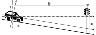
- ⁇ Recognition judgment in height direction> 3 to 6 are diagrams for explaining recognition determination in the height direction of the traffic light 32.
- the height of the driver's line of sight (the position of the driver's eyes in the height direction) of the vehicle 7 will be explained.
- the height of the driver's line of sight is the sum of the altitude of the vehicle 7, the height from the road surface to the bottom of the angle of view of the in-vehicle camera 24, and the height from the bottom of the angle of view of the in-vehicle camera 24 to the driver's eyes.
- the altitude of the vehicle 7 is the altitude determined by the vehicle position calculation unit 14.
- the height from the road surface to the bottom of the viewing angle of the in-vehicle camera 24 is information included in the vehicle data 25, and corresponds to the height 36 shown in FIG. 3.
- the height from the bottom of the angle of view of the in-vehicle camera 24 to the driver's eyes corresponds to the height 37 shown in FIGS. 3 and 4.
- the height 37 is determined, for example, by converting the number of pixels from the bottom of the angle of view in FIG. 4 to the driver's eyes into a distance.
- the height of the traffic light 32 is the sum of the altitude of the traffic light 32 and the height 39 of the traffic light 32 from the road surface.
- the altitude of the traffic light 32 and the height 39 of the traffic light 32 from the road surface are obtained from the map data 12.
- the angle of the traffic light 32 as seen from the driver's eyes is determined from the difference between the height of the driver's line of sight and the height of the traffic light 32, and the distance between the vehicle 7 and the traffic light 32.
- the distance between the vehicle 7 and the traffic light 32 is determined from the current position of the vehicle 7 and the position of the traffic light 32.
- the height 38 shown in FIG. 5 corresponds to the sum of the heights 36 and 37 shown in FIG. 3.
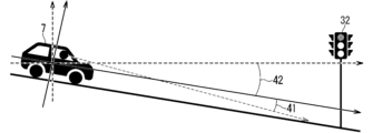
- an angle 41 indicates the angle of the driver's line of sight determined by the driver information calculation unit 26 with respect to a plane parallel to the road surface of the vehicle 7 (the direction in which the vehicle 7 is tilted). Further, the angle 42 indicates the inclination of the vehicle 7 determined by the vehicle inclination calculation unit 16. The angle of the driver's line of sight when viewed from outside the vehicle 7 is the sum of angles 41 and 42.
- the feature recognition determination unit 6 makes a determination by comparing the angle of the traffic light 32 as seen from the driver's eyes and the angle of the driver's line of sight as seen from outside the vehicle 7 (recognition determination of the height direction of the traffic light 32). )do. Specifically, the feature recognition determination unit 6 determines whether the angle of the traffic light 32 as seen from the driver's eyes and the angle of the driver's line of sight as seen from outside the vehicle 7 completely match or are within a predetermined angle range. When , it is determined that the driver is looking at the traffic light 32 in the height direction.
- FIG. 7 is a diagram for explaining the recognition determination of the traffic light 32 in the lateral direction.
- the angle 43 is the angle of the direction of the traffic light 32 with respect to the direction of the vehicle 7.
- the direction of the traffic light 32 is determined based on the current position of the vehicle 7 and the position of the traffic light 32.
- the angle 44 is the angle of the driver's line of sight when viewed from outside the vehicle 7, and is the angle of the driver's line of sight with respect to the azimuth of the vehicle 7.
- the feature recognition determination unit 6 makes a determination (recognition determination of the lateral direction of the traffic light 32) by comparing the angle 43 and the angle 44. Specifically, the feature recognition determining unit 6 determines that the driver is looking at the traffic light 32 in the lateral direction when the angle 43 and the angle 44 completely match or are within a predetermined angle range.
- FIG. 8 is a flowchart showing an example of the operation of the system in the vehicle 7 including the driving support device 21.
- the vehicle is the "own vehicle.”
- the operation shown in FIG. 8 is based on the premise that after detecting a traffic light present at an intersection within a predetermined distance A in the direction of travel of the host vehicle, the vehicle always passes through this intersection. Furthermore, the operation shown in FIG. 8 uses two variables: the previous signal display and the recognized flag.
- the predetermined distances A, B, and C are values defined below, with distance A being the longest and distance C being the shortest. Note that distance A, distance B, and distance C change depending on the speed of the vehicle and the slope of the road.
- - Distance A This distance indicates that it is dangerous if the driver does not recognize the traffic light at least once when the distance between the vehicle and the traffic light is within distance A.
- ⁇ Distance B If the distance between the vehicle and the stop line is within distance B, and the driver never sees the traffic light from distance A, and the traffic light is red or yellow, a warning will be issued to the driver. This is the distance that indicates that it is necessary.
- the distance B may be the distance between the own vehicle and the traffic light.
- - Distance C This is a distance indicating that no warning will be issued to the driver when the distance between the own vehicle and the stop line is within distance C. Note that the distance C may be the distance between the own vehicle and the traffic light.
- step S1 the feature determination unit 5 clears the previous signal display.
- step S2 the positioning unit 13 updates the position, altitude, and position accuracy of the own vehicle. Additionally, the map information creation unit 18 updates map information around the own vehicle.
- step S3 the position accuracy calculation unit 15 determines whether the accuracy of the current position of the own vehicle determined by the vehicle position calculation unit 14 is high. If the accuracy of the current position of the vehicle is high, the process moves to step S4. On the other hand, if the accuracy of the current position of the own vehicle is not high, the process returns to step S2.
- step S4 the feature determining unit 5 determines whether a traffic light exists within a predetermined distance A (first distance) from the own vehicle. If the traffic light exists within distance A from the host vehicle, the process moves to step S5. On the other hand, if there is no traffic light within distance A from the host vehicle, the process returns to step S2.
- a predetermined distance A first distance
- step S5 the signal display determination unit 29 updates the current signal display of the traffic light. Specifically, the signal display determination unit 29 determines the signal display of the traffic light (blue, yellow, or (red).
- step S6 the feature determination unit 5 determines whether the current signal display and the previous signal display are the same. If the current signal display and the previous signal display are the same, the process moves to step S9. On the other hand, if the current signal display and the previous signal display are not the same, the process moves to step S7.
- step S7 the feature determination unit 5 clears the recognized flag.
- This process is a process for re-determining whether the driver has recognized the traffic light when the signal display has changed.
- step S8 the feature determination unit 5 sets the current signal display to the previous signal display.
- step S9 the feature determination unit 5 determines whether the recognized flag is ON. If the recognized flag is ON, the process moves to step S10. On the other hand, if the recognized flag is not ON, the process moves to step S13.
- step S10 the feature determination unit 5 determines whether the stop line in front of the intersection exists within a predetermined distance C (second distance) from the own vehicle. If the stop line exists within distance C from the host vehicle, the process moves to step S11. On the other hand, if the stop line does not exist within distance C from the host vehicle, the process returns to step S2.
- This process is a process for warning the driver if the driver does not recognize the traffic light when the signal display of the traffic light changes when the own vehicle is farther than distance C.
- step S11 the feature determination unit 5 compares the current position of the own vehicle with the position of the intersection, and determines whether the own vehicle has passed through the intersection. If the own vehicle has passed the intersection, the operation shown in FIG. 8 ends. On the other hand, if the host vehicle has not passed through the intersection, the process moves to step S12.
- step S12 the positioning unit 13 updates the position, altitude, and position accuracy of the own vehicle. Additionally, the map information creation unit 18 updates map information around the own vehicle.
- step S13 the feature recognition determination unit 6 determines whether the driver recognizes the traffic light. If the driver recognizes the traffic light, the process moves to step S14. On the other hand, if the driver does not recognize the traffic light, the process moves to step S15.
- step S14 the feature determination unit 5 turns on the recognized flag.
- step S15 the feature determination unit 5 determines whether the stop line in front of the intersection exists within a predetermined distance B from the own vehicle. If the stop line exists within distance B from the host vehicle, the process moves to step S16. On the other hand, if the stop line does not exist within distance B from the host vehicle, there is no need to issue a warning yet and the process returns to step S2.
- step S16 the signal display determination unit 29 determines whether the signal display of the traffic light is red or yellow. If the signal display of the traffic light is red or yellow, the process moves to step S17. On the other hand, if the signal display of the traffic light is not red or yellow but blue, the process moves to step S18.
- step S17 the output control unit 23 controls the display output unit 30 and the audio output unit 31 to output a warning urging the driver to look at the traffic lights, or a warning urging the driver to stop or decelerate.
- the output control unit 23 may control the display output unit 30 and the audio output unit 31 so that the warning is output from both the display output unit 30 and the audio output unit 31, and the display output unit 30 and the audio output unit 31 may output the warning.
- the display output section 30 or the audio output section 31 may be controlled so that either one of the sections 31 outputs a warning.
- step S18 the feature determination unit 5 determines whether the stop line in front of the intersection exists within a predetermined distance C from the own vehicle. If the stop line exists within distance C from the host vehicle, the process moves to step S19. On the other hand, if the stop line does not exist within distance C from the host vehicle, the process returns to step S2. This process is necessary to determine whether the driver recognizes the traffic light when the traffic light changes from blue to yellow or red after the process, and to issue a warning if the driver does not recognize the traffic light. , when the own vehicle is further away than distance C and the signal display is blue, this is a process for repeatedly confirming whether the signal display does not change.
- step S19 the feature determining unit 5 compares the current position of the own vehicle with the position of the intersection to determine whether the own vehicle has passed through the intersection. If the own vehicle has passed the intersection, the process moves to step S20. On the other hand, if the own vehicle has not passed through the intersection, the process moves to step S21.
- step S20 the output control unit 23 controls the display output unit 30 and the audio output unit 31 to output a warning urging the driver to pay attention to the traffic lights or a warning urging the driver to take a break.
- the output control section 23 may control the display output section 30 and the audio output section 31 so that the warning is output from both the display output section 30 and the audio output section 31.
- the display output section 30 or the audio output section 31 may be controlled so that the warning is output from either of the sections 31.
- step S21 the positioning unit 13 updates the position, altitude, and position accuracy of the own vehicle. Additionally, the map information creation unit 18 updates map information around the own vehicle.
- the detected traffic light is removed from the target by changing the route or entering a store before reaching the intersection. If it comes off, repeat the operation shown in FIG. 8 from the beginning.
- the driving support device 21 includes conventionally used information (the current position of the vehicle, the altitude of the vehicle, the position of the feature, the height of the feature from the ground, the position of the driver's eyes, and In addition to the direction of the driver's line of sight), it is determined whether the driver recognizes the feature using the inclination of the vehicle, the orientation of the vehicle, the elevation of the feature, and the slope of the road on which the vehicle is traveling. This makes it possible to accurately determine whether the driver recognizes the feature.
- ⁇ Modification 1> When the feature determination unit 5 detects a plurality of traffic lights within a predetermined distance (for example, distance A) in the traveling direction of the road on which the vehicle is traveling, the feature recognition determination unit 6 detects the following for each traffic light: It may also be determined whether the driver recognizes the traffic light.
- a predetermined distance for example, distance A
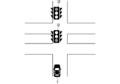
- FIG. 9 there are two traffic lights 32 within a predetermined distance in the direction of travel of the road on which the vehicle 7 is traveling, and the signal display of the traffic light 32 that is closer to the vehicle 7 is blue, and the vehicle The signal display of the traffic light 32 farther from 7 is red. For example, if the driver recognizes a nearby traffic light 32 but does not recognize a distant traffic light 32, a warning is output.
- the feature determining unit 5 may determine which feature is the target based on a preset travel route of the vehicle 7.
- the driving route may be obtained in advance from a navigation system, for example.
- the driving support device 21 acquires vehicle information, map information, driver information, and determines whether a traffic light exists within a predetermined distance from the vehicle 7 in the traveling direction of the vehicle 7.
- the display output unit and It includes a processing circuit for controlling the audio output section.
- the processing circuit may be dedicated hardware, and may be a processor (CPU, central processing unit, processing unit, arithmetic unit, microprocessor, microcomputer, DSP (Digital Signal Processor)) that executes a program stored in memory. ).
- the processing circuit 45 may be, for example, a single circuit, a composite circuit, a programmed processor, a parallel programmed processor, or an ASIC (Application Specific Integrated Circuit). , FPGA (Field Programmable Gate Array), or a combination of these.
- Each function of the vehicle information acquisition section 2, the map information acquisition section 3, the driver information acquisition section 4, the feature determination section 5, the feature recognition determination section 6, the position information use determination section 22, and the output control section 23 is implemented by a processing circuit. 45, or each function may be implemented collectively in one processing circuit 45.
- the processing circuit 45 is the processor 46 shown in FIG. 11, the vehicle information acquisition section 2, the map information acquisition section 3, the driver information acquisition section 4, the feature determination section 5, the feature recognition determination section 6, and the position information use determination section 22 and the output control unit 23 are realized by software, firmware, or a combination of software and firmware.
- Software or firmware is written as a program and stored in memory 47.
- the processor 46 implements each function by reading and executing programs recorded in the memory 47. That is, the driving support device 21 performs a step of acquiring vehicle information, a step of acquiring map information, a step of acquiring driver information, and a step in which a traffic light exists within a predetermined distance from the vehicle 7 in the traveling direction of the vehicle 7.
- a memory 47 is provided for storing a program that results in the steps of controlling the display output unit and the audio output unit.
- These programs also include a vehicle information acquisition section 2, a map information acquisition section 3, a driver information acquisition section 4, a feature determination section 5, a feature recognition determination section 6, a position information use determination section 22, and an output control section 23. It can also be said that it causes a computer to execute a procedure or method.
- memory refers to nonvolatile or volatile memory such as RAM (Random Access Memory), ROM (Read Only Memory), flash memory, EPROM (Erasable Programmable Read Only Memory), and EEPROM (Electrically Erasable Programmable Read Only Memory).
- RAM Random Access Memory
- ROM Read Only Memory
- flash memory EPROM (Erasable Programmable Read Only Memory)
- EEPROM Electrical Erasable Programmable Read Only Memory
- the storage medium may be a flexible semiconductor memory, a magnetic disk, a flexible disk, an optical disk, a compact disk, a DVD (Digital Versatile Disc), or any storage medium that will be used in the future.
- map information acquisition section 3 Regarding the functions of the vehicle information acquisition section 2, map information acquisition section 3, driver information acquisition section 4, feature determination section 5, feature recognition determination section 6, position information use determination section 22, and output control section 23, Some functions may be realized by dedicated hardware, and other functions may be realized by software or firmware.
- the processing circuit can realize each of the above functions using hardware, software, firmware, or a combination thereof.
- 1 driving support device 2 vehicle information acquisition unit, 3 map information acquisition unit, 4 driver information acquisition unit, 5 feature determination unit, 6 feature recognition determination unit, 7 vehicle, 8 gyro sensor, 9 acceleration sensor, 10 GNSS reception machine, 11 vehicle speed sensor, 12 map data, 13 positioning unit, 14 vehicle position calculation unit, 15 position accuracy calculation unit, 16 vehicle tilt calculation unit, 17 vehicle orientation calculation unit, 18 map information creation unit, 19 road information creation unit, 20 Sign information creation unit, 21 Driving support device, 22 Location information use determination unit, 23 Output control unit, 24 In-vehicle camera, 25 Vehicle data, 26 Driver information calculation unit, 27 Ex-vehicle camera, 28 Communication reception unit, 29 Signal display determination Part, 30 Display output section, 31 Audio output section, 32 Traffic light, 33 Signal judgment section, 34 Signal display section, 35 Signal display transmission section, 36 Height, 37 Height, 38 Height, 39 Height, 40 Distance, 41 angle, 42 angle, 43 angle, 44 angle, 45 processing circuit, 46 processor, 47 memory.
Landscapes
- Physics & Mathematics (AREA)
- General Physics & Mathematics (AREA)
- Traffic Control Systems (AREA)
- Navigation (AREA)
Abstract
本開示は、ドライバが地物を認識しているか否かを精度良く判定することが可能な運転支援装置を提供することを目的とする。本開示による運転支援装置は、車両の現在位置、車両の現在位置の標高、車両の傾き、および車両の方位を含む車両情報を取得する車両情報取得部と、車両の周辺に存在する地物の位置、地物の標高、地物の地上からの高さ、および車両が走行する道路の勾配を含む地図情報を取得する地図情報取得部と、車両のドライバの目の位置、およびドライバの視線方向を含むドライバ情報を取得するドライバ情報取得部と、車両情報および地図情報に基づいて車両の進行方向であって車両から第1距離以内に地物が存在するか否かを判定する地物判定部と、車両から第1距離以内に地物が存在すると判定したとき、車両情報、地図情報、およびドライバ情報に基づいて、ドライバが地物を認識しているか否かを判定する地物認識判定部とを備える。
Description
本開示は、進行方向に存在する地物を認識していないドライバに対して適切な警告を行う運転支援装置および運転支援方法に関する。
従来、自車の進行方向の交差点に信号機または標識などの地物がある場合において、当該地物の位置、地物の地上からの高さ、自車の位置、自車の位置の標高、ドライバの顔の向き、およびドライバの視線方向の情報に基づいて、ドライバが当該地物を認識しているか否かを判定し、ドライバが地物を認識していないと判定した場合はドライバに対して警告を行う技術が開示されている(例えば、特許文献1参照)。
交差点周辺の道路は、平坦かつ直線であるとは限らず、カーブ、上り、または下りとなっている場合もある。しかし、特許文献1では、自車から交差点までの道路が直線であり、かつ自車が道路に沿った前方を向いていることを前提としている。そして、自車を基準点とした地物の位置および方向を、自車の位置および標高と、地物の位置および路面からの高さとから計算して求めている。
従って、交差点前の道路がカーブである場合、または車線変更などの運転操作によって自車が道路に沿った前方を向いていない場合は、自車を基準点とした地物の実際の位置および方向が計算とずれてしまう場合がある。また、交差点前の道路が上りまたは下りであって自車が傾いている場合、または自車の標高と地物の標高とが異なる場合も、自車を基準点とした地物の実際の位置および方向が計算とずれてしまう場合がある。このように、自車を基準点とした地物の実際の位置および方向が計算とずれてしまうと、ドライバが地物を認識しているか否かを精度良く判定することができない。
本開示は、このような問題を解決するためになされたものであり、ドライバが地物を認識しているか否かを精度良く判定することが可能な運転支援装置および運転支援方法を提供することを目的とする。
上記の課題を解決するために、本開示による運転支援装置は、車両の現在位置、車両の現在位置の標高、車両の傾き、および車両の方位を含む車両情報を取得する車両情報取得部と、車両の周辺に存在する地物の位置、地物の標高、地物の地上からの高さ、および車両が走行する道路の勾配を含む地図情報を取得する地図情報取得部と、車両のドライバの目の位置、およびドライバの視線方向を含むドライバ情報を取得するドライバ情報取得部と、車両情報取得部が取得した車両情報と、地図情報取得部が取得した地図情報とに基づいて、車両の進行方向であって車両から予め定められた第1距離以内に地物が存在するか否かを判定する地物判定部と、地物判定部が車両から第1距離以内に地物が存在すると判定したとき、車両情報取得部が取得した車両情報と、地図情報取得部が取得した地図情報と、ドライバ情報取得部が取得したドライバ情報とに基づいて、ドライバが地物を認識しているか否かを判定する地物認識判定部とを備える。
本開示によれば、ドライバが地物を認識しているか否かを精度良く判定することが可能となる。
本開示の目的、特徴、態様、および利点は、以下の詳細な説明と添付図面とによって、より明白となる。
<実施の形態>
<構成>
図1は、実施の形態による運転支援装置1の構成の一例を示すブロック図である。図1に示すように、運転支援装置1は、車両情報取得部2と、地図情報取得部3と、ドライバ情報取得部4と、地物判定部5と、地物認識判定部6とを備えている。
<構成>
図1は、実施の形態による運転支援装置1の構成の一例を示すブロック図である。図1に示すように、運転支援装置1は、車両情報取得部2と、地図情報取得部3と、ドライバ情報取得部4と、地物判定部5と、地物認識判定部6とを備えている。
車両情報取得部2は、車両の現在位置、車両の現在位置の標高、車両の傾き、および車両の方位を含む車両情報を取得する。地図情報取得部3は、車両の周辺に存在する地物の現在位置、地物の現在位置の標高、地物の地上からの高さ、および車両が走行する道路の勾配を含む地図情報を取得する。ドライバ情報取得部4は、車両のドライバの目の位置、およびドライバの視線方向を含むドライバ情報を取得する。
地物判定部5は、車両情報取得部2が取得した車両情報と、地図情報取得部3が取得した地図情報とに基づいて、車両の進行方向であって車両から予め定められた第1距離以内に地物が存在するか否かを判定する。地物認識判定部6は、地物判定部5が車両から第1距離以内に地物が存在すると判定したとき、車両情報取得部2が取得した車両情報と、地図情報取得部3が取得した地図情報と、ドライバ情報取得部4が取得したドライバ情報とに基づいて、ドライバが地物を認識しているか否かを判定する。
次に、図1に示す運転支援装置1を含む他の構成について説明する。
図2は、他の構成に係る運転支援装置21を含むシステム全体の構成を示すブロック図である。図2に示すシステムは、車両7と信号機32とに大別される。車両7と信号機32とは、通信可能に接続される。以下では、それぞれの構成について説明する。
なお、以下の説明では、地物は信号機32であるものとして説明するが、これに限るものではない。地物は、例えば、標識または路面標示などであってもよい。
<車両の構成>
車両7には、ジャイロセンサ8、加速度センサ9、GNSS(Global Navigation Satellite System)受信機10、車速センサ11、地図データ12、測位部13、地図情報作成部18、運転支援装置21、車内カメラ24、車両データ25、ドライバ情報計算部26、車外カメラ27、通信受信部28、信号表示判定部29、表示出力部30、および音声出力部31が搭載されている。
車両7には、ジャイロセンサ8、加速度センサ9、GNSS(Global Navigation Satellite System)受信機10、車速センサ11、地図データ12、測位部13、地図情報作成部18、運転支援装置21、車内カメラ24、車両データ25、ドライバ情報計算部26、車外カメラ27、通信受信部28、信号表示判定部29、表示出力部30、および音声出力部31が搭載されている。
なお、ジャイロセンサ8、加速度センサ9、GNSS受信機10、車速センサ11、地図データ12、測位部13、および地図情報作成部18は、高精度ロケータを構成している。また、車内カメラ24およびドライバ情報計算部26は、DMS(Driver Monitoring System)を構成している。
ジャイロセンサ8は、車両7の角速度を検知する。加速度センサ9は、車両7の加速度を検知する。GNSS受信機10は、GNSS衛星から、車両7の現在位置、当該現在位置における標高、および方位を含むGNSS情報を受信する。車両7の現在位置は、緯度および経度で表される座標である。車速センサ11は、車両7の速度を検知する。
地図データ12は、道路の位置、道路の標高、道路の勾配、道路における車線中心線、道路における区画線、地物の位置、地物の標高、標識、および路面標示などの情報を含む。地図データ12は、メモリまたはHDD(Hard Disk Drive)などの記憶媒体に記憶されている。なお、地図データ12を記憶する記憶媒体は、車両7の外部に設けてもよい。この場合、車両7は、外部の記憶媒体から地図データ12を取得することになる。
測位部13は、車両位置計算部14、位置精度計算部15、車両傾き計算部16、および車両方位計算部17を有している。車両位置計算部14は、ジャイロセンサ8、加速度センサ9、GNSS受信機10、および車速センサ11から取得した各種情報に基づいて、車両7の現在位置、および当該現在位置の標高を計算する。以下では、車両7の現在位置の標高のことを、単に「車両7の標高」という。なお、車両位置計算部14は、車両7の現在位置の標高を地図データ12から取得し、当該標高を車両7の標高としてもよい。
位置精度計算部15は、車両位置計算部14が求めた車両7の現在位置の精度を推定する。例えば、位置精度計算部15は、GNSS受信機10におけるGNSS情報の受信状態が良い場合は、車両7の現在位置の精度が高いと推定する。また、位置精度計算部15は、GNSS受信機10が受信したGNSS情報が時間的にぶれていない場合は、車両7の現在位置の精度が高いと推定する。さらに、位置精度計算部15は、車両位置計算部14が求めた車両7の現在位置と地図データ12とを照合して車両7が道路上を走行している場合は、車両7の現在位置の精度が高いと推定する。
車両傾き計算部16は、ジャイロセンサ8から取得した情報に基づいて、車両7の傾きを計算する。車両方位計算部17は、ジャイロセンサ8、加速度センサ9、およびGNSS受信機10から取得した各種情報に基づいて、車両7の方位を計算する。
地図情報作成部18は、道路情報作成部19および標識情報作成部20を有している。道路情報作成部19は、車両位置計算部14が求めた車両7の現在位置と、地図データ12とに基づいて、車両7の周辺の地図情報に含まれる道路情報を作成する。道路情報は、例えば、道路の位置、標高、勾配、車線中心線、および区画線などの情報を含む。
標識情報作成部20は、車両位置計算部14が求めた車両7の現在位置と、地図データ12とに基づいて、車両7の周辺の地図情報に含まれる標識情報を作成する。標識情報は、例えば、地物(信号機など)、規制標識(駐車禁止、最高速度など)、指示標識(安全地帯、駐車可など)、警戒標識(丁字路あり、車線数減少など)、および路面標示(停止線、横断歩道など)のそれぞれの種別、位置、標高、および路面からの高さの情報を含む。
車内カメラ24は、少なくともドライバの顔を撮影する。車両データ25は、車両7に関するデータであり、車両7のサイズ、および路面から車内カメラ24の画角の底辺までの高さの情報などを含む。
ドライバ情報計算部26は、車内カメラ24が撮影したドライバの顔の画像データと、車両データ25とに基づいて、ドライバ情報を求める。ドライバ情報は、ドライバの目の位置、視線方向、および顔の向きを含む。ドライバの目の位置、視線方向、および顔の向きは、周知の技術を用いて求めることができる。
車外カメラ27は、車両7の周辺に存在する地物を撮影する。通信受信部28は、信号機32から、信号表示の情報を受信する。信号表示の情報は、信号機32が表示する青色、黄色、および赤色のいずれかの情報を含む。信号表示判定部29は、通信受信部28が受信した信号表示の情報が、青色、黄色、および赤色のいずれの情報を含んでいるのかを判定する。なお、信号表示判定部29は、運転支援装置21が備える構成としてもよい。
運転支援装置21は、車両情報取得部2、地図情報取得部3、ドライバ情報取得部4、地物判定部5、地物認識判定部6、位置情報使用判定部22、および出力制御部23を有している。なお、運転支援装置21は、車載用ナビゲーション装置、すなわちカーナビゲーション装置だけでなく、車両に搭載可能なPND(Portable Navigation Device)、および車両の外部に設けられたサーバなどを適宜に組み合わせてシステムとして構築してもよい。この場合、運転支援装置21の各機能または各構成要素は、システムを構築する各機能に分散して配置される。
車両情報取得部2は、測位部13から、車両7の現在位置、車両7の標高、車両7の傾き、および車両7の方位を含む車両情報を取得する。位置情報使用判定部22は、位置精度計算部15が求めた車両7の現在位置の精度(推定結果)に基づいて、車両7の現在位置を使用するか否かを判定する。具体的には、位置情報使用判定部22は、精度が良いと位置精度計算部15が判定した車両7の現在位置を使用すると判定し、精度が悪いと位置精度計算部15が判定した車両7の現在位置は使用しないと判定する。
地図情報取得部3は、地図情報作成部18から地図情報を取得する。ドライバ情報取得部4は、ドライバ情報計算部26からドライバ情報を取得する。
地物判定部5は、車両情報取得部2が取得した車両情報と、地図情報取得部3が取得した地図情報とに基づいて、車両7の進行方向であって車両7から予め定められた距離以内に信号機32が存在するか否かを判定する。
地物認識判定部6は、車両情報取得部2が取得した車両情報と、地図情報取得部3が取得した地図情報と、ドライバ情報取得部4が取得したドライバ情報と、地物判定部5の判定結果とに基づいて、車両7から予め定められた距離以内に信号機32が存在する場合に、ドライバが信号機を認識しているか否かを判定する。
出力制御部23は、ドライバが地物を認識していないと地物認識判定部6が判定した場合、ドライバに対して警告または注意を出力するように表示出力部30および音声出力部31を制御する。表示出力部30は、ドライバに対して警告または注意に関する情報を表示する。音声出力部31は、ドライバに対して警告または注意に関する音声を出力する。
<信号機の構成>
信号機32は、信号判断部33、信号表示部34、および信号表示送信部35を備える。信号判断部33は、信号表示部34に青色、黄色、および赤色のいずれを表示するのかを判断し、決定した色を表示するように信号表示部34を制御する。また、信号判断部33は、信号表示部34に表示する色に関する情報(信号表示の情報)を車両7に送信するように信号表示送信部35を制御する。
信号機32は、信号判断部33、信号表示部34、および信号表示送信部35を備える。信号判断部33は、信号表示部34に青色、黄色、および赤色のいずれを表示するのかを判断し、決定した色を表示するように信号表示部34を制御する。また、信号判断部33は、信号表示部34に表示する色に関する情報(信号表示の情報)を車両7に送信するように信号表示送信部35を制御する。
信号表示部34は、信号判断部33が決定した色を表示(信号表示)する。信号表示送信部35は、車両7を含む信号機32の周辺に存在する車両に信号表示の情報を送信する。
<信号機の認識判定>
地物認識判定部6による信号機32の認識判定について、高さ方向の認識判定と、横方向の認識判定とに分けて説明する。高さ方向の認識判定とは、ドライバが信号機32を見ているか否かを高さ方向で判定することをいう。横方向の認識判定とは、ドライバが信号機32を見ているか否かを横方向で判定することをいう。
地物認識判定部6による信号機32の認識判定について、高さ方向の認識判定と、横方向の認識判定とに分けて説明する。高さ方向の認識判定とは、ドライバが信号機32を見ているか否かを高さ方向で判定することをいう。横方向の認識判定とは、ドライバが信号機32を見ているか否かを横方向で判定することをいう。
地物認識判定部6は、下記で説明する高さ方向の認識判定と、横方向の認識判定との両方においてドライバが信号機32を認識していると判定すると、ドライバが信号機32を認識していると判定する。
<高さ方向の認識判定>
図3~6は、信号機32の高さ方向の認識判定を説明するための図である。
図3~6は、信号機32の高さ方向の認識判定を説明するための図である。
まず、車両7のドライバの目線の高さ(高さ方向におけるドライバの目の位置)について説明する。ドライバの目線の高さは、車両7の標高と、路面から車内カメラ24の画角の底辺までの高さと、車内カメラ24の画角の底辺からドライバの目までの高さとを合わせた値である。車両7の標高は、車両位置計算部14が求めた標高である。路面から車内カメラ24の画角の底辺までの高さは、車両データ25に含まれる情報であり、図3に示す高さ36に相当する。車内カメラ24の画角の底辺からドライバの目までの高さは、図3,4に示す高さ37に相当する。高さ37は、例えば、図4における画角の底面からドライバの目までのピクセル数を距離に換算することによって求められる。
次に、信号機32の高さについて説明する。信号機32の高さは、信号機32の標高と、信号機32の路面からの高さ39とを合わせた値である。信号機32の標高、および信号機32の路面からの高さ39は、地図データ12から得られる。
次に、ドライバの目から見た信号機32の角度について説明する。図5に示すように、ドライバの目から見た信号機32の角度は、ドライバの目線の高さと信号機32の高さとの差分と、車両7と信号機32との距離とから求められる。車両7と信号機32との距離は、車両7の現在位置と、信号機32の位置とから求められる。なお、図5に示す高さ38は、図3に示す高さ36と高さ37とを合わせた値に相当する。
次に、車両7の外から見たドライバの視線方向の角度について説明する。図6において、角度41は、車両7における路面に平行な面(車両7が傾いている方向)に対する、ドライバ情報計算部26が求めたドライバの視線方向の角度を示している。また、角度42は、車両傾き計算部16が求めた車両7の傾きを示している。車両7の外から見たドライバの視線方向の角度は、角度41と角度42とを合わせた角度である。
地物認識判定部6は、ドライバの目から見た信号機32の角度と、車両7の外から見たドライバの視線方向の角度とを比較することによって判定(信号機32の高さ方向の認識判定)する。具体的には、地物認識判定部6は、ドライバの目から見た信号機32の角度と、車両7の外から見たドライバの視線方向の角度とが完全一致または予め定められた角度範囲以内であるとき、高さ方向においてドライバが信号機32を見ていると判定する。
<横方向の認識判定>
図7は、信号機32の横方向の認識判定を説明するための図である。
図7は、信号機32の横方向の認識判定を説明するための図である。
角度43は、車両7の方位に対する信号機32の方位の角度である。信号機32の方位は、車両7の現在位置と、信号機32の位置とに基づいて求められる。角度44は、車両7の外から見たドライバの視線方向の角度であり、車両7の方位に対するドライバの視線方向の角度である。
地物認識判定部6は、角度43と角度44とを比較することによって判定(信号機32の横方向の認識判定)する。具体的には、地物認識判定部6は、角度43と角度44とが完全一致または予め定められた角度範囲以内であるとき、横方向においてドライバが信号機32を見ていると判定する。
<動作>
図8は、運転支援装置21を含む車両7におけるシステムの動作の一例を示すフローチャートである。以下では、車両は「自車」であるものとして説明する。図8に示す動作は、自車の進行方向の予め定められた距離A以内の交差点に存在する信号機を検出した後に、この交差点を必ず通過することを前提としている。また、図8に示す動作では、前回の信号表示と、認識済みフラグとの2つの変数を使用している。
図8は、運転支援装置21を含む車両7におけるシステムの動作の一例を示すフローチャートである。以下では、車両は「自車」であるものとして説明する。図8に示す動作は、自車の進行方向の予め定められた距離A以内の交差点に存在する信号機を検出した後に、この交差点を必ず通過することを前提としている。また、図8に示す動作では、前回の信号表示と、認識済みフラグとの2つの変数を使用している。
予め定められた距離A、距離B、および距離Cは、それぞれ下記で定義される値であり、距離Aが最も長く、距離Cが最も短い。なお、距離A、距離B、および距離Cは、車両の速度と、道路の勾配とによって変化する。
・距離A:自車と信号機との間が距離A以内であるときに、ドライバが信号機を一度以上は認識しないと危険であることを示す距離である。
・距離B:自車と停止線との間が距離B以内であるときに、ドライバが距離Aから信号機を一度も見ず、かつ信号表示が赤色または黄色である場合、ドライバに対して警告が必要であることを示す距離である。なお、距離Bは、自車と信号機との間の距離であってもよい。
・距離C:自車と停止線との間が距離C以内であるときに、ドライバに警告を出さないことを示す距離である。なお、距離Cは、自車と信号機との間の距離であってもよい。
・距離A:自車と信号機との間が距離A以内であるときに、ドライバが信号機を一度以上は認識しないと危険であることを示す距離である。
・距離B:自車と停止線との間が距離B以内であるときに、ドライバが距離Aから信号機を一度も見ず、かつ信号表示が赤色または黄色である場合、ドライバに対して警告が必要であることを示す距離である。なお、距離Bは、自車と信号機との間の距離であってもよい。
・距離C:自車と停止線との間が距離C以内であるときに、ドライバに警告を出さないことを示す距離である。なお、距離Cは、自車と信号機との間の距離であってもよい。
ステップS1において、地物判定部5は、前回の信号表示をクリアする。
ステップS2において、測位部13は、自車の位置、標高、および位置精度を更新する。また、地図情報作成部18は、自車の周辺の地図情報を更新する。
ステップS3において、位置精度計算部15は、車両位置計算部14が求めた自車の現在位置の精度が高いか否かを判断する。自車の現在位置の精度が高い場合は、ステップS4に移行する。一方、自車の現在位置の精度が高くない場合は、ステップS2に戻る。
ステップS4において、地物判定部5は、信号機が自車から予め定められた距離A(第1距離)以内に存在するか否かを判断する。信号機が自車から距離A以内に存在する場合は、ステップS5に移行する。一方、信号機が自車から距離A以内に存在しない場合は、ステップS2に戻る。
ステップS5において、信号表示判定部29は、信号機の現在の信号表示を更新する。具体的には、信号表示判定部29は、通信受信部28から取得した信号機の信号表示の情報、または車外カメラ27が撮影した信号機の画像に基づいて、信号機の信号表示(青色、黄色、または赤色)を更新する。
ステップS6において、地物判定部5は、現在の信号表示と前回の信号表示とが同じであるか否かを判断する。現在の信号表示と前回の信号表示とが同じである場合は、ステップS9に移行する。一方、現在の信号表示と前回の信号表示とが同じでない場合は、ステップS7に移行する。
ステップS7において、地物判定部5は、認識済みフラグをクリアする。この処理は、信号表示が変わった場合に、ドライバが信号機を認識したか否かを再度判定するための処理である。
ステップS8において、地物判定部5は、前回の信号表示に現在の信号表示をセットする。
ステップS9において、地物判定部5は、認識済みフラグがONであるか否かを判断する。認識済みフラグがONである場合は、ステップS10に移行する。一方、認識済みフラグがONでない場合は、ステップS13に移行する。
ステップS10において、地物判定部5は、交差点前の停止線が自車から予め定められた距離C(第2距離)以内に存在するか否かを判断する。停止線が自車から距離C以内に存在する場合は、ステップS11に移行する。一方、停止線が自車から距離C以内に存在しない場合は、ステップS2に戻る。この処理は、自車が距離Cよりも遠い時に信号機の信号表示が変わった際に、ドライバが信号機を認識していなかったらドライバに警告をするための処理である。
ステップS11において、地物判定部5は、自車の現在位置と、交差点の位置とを比較して、自車が交差点を通過したか否かを判断する。自車が交差点を通過した場合は、図8の動作を終了する。一方、自車が交差点を通過していない場合は、ステップS12に移行する。
ステップS12において、測位部13は、自車の位置、標高、および位置精度を更新する。また、地図情報作成部18は、自車の周辺の地図情報を更新する。
ステップS13において、地物認識判定部6は、ドライバが信号機を認識しているか否かを判断する。ドライバが信号機を認識している場合は、ステップS14に移行する。一方、ドライバが信号機を認識していない場合は、ステップS15に移行する。
ステップS14において、地物判定部5は、認識済みフラグをONにする。
ステップS15において、地物判定部5は、交差点前の停止線が自車から予め定められた距離B以内に存在するか否かを判断する。停止線が自車から距離B以内に存在する場合は、ステップS16に移行する。一方、停止線が自車から距離B以内に存在しない場合は、まだ警告を出す必要がないためステップS2に戻る。
ステップS16において、信号表示判定部29は、信号機の信号表示が赤色または黄色であるか否かを判断する。信号機の信号表示が赤色または黄色である場合は、ステップS17に移行する。一方、信号機の信号表示が赤色または黄色でなく青色である場合は、ステップS18に移行する。
ステップS17において、出力制御部23は、ドライバに対して信号機を見るように促す警告、あるいは、停車または減速を促す警告を出力するように表示出力部30および音声出力部31を制御する。このとき、出力制御部23は、表示出力部30および音声出力部31の両方から警告を出力するように表示出力部30および音声出力部31を制御してもよく、表示出力部30または音声出力部31のいずれか一方から警告を出力するように表示出力部30または音声出力部31を制御してもよい。
ステップS18において、地物判定部5は、交差点前の停止線が自車から予め定められた距離C以内に存在するか否かを判断する。停止線が自車から距離C以内に存在する場合は、ステップS19に移行する。一方、停止線が自車から距離C以内に存在しない場合は、ステップS2に戻る。この処理は、当該処理の後に信号表示が青色から黄色または赤色に変わった時にドライバが信号機を認識しているか否かを判断し、ドライバが信号機を認識していない場合は警告する必要があるため、自車が距離Cよりも遠くかつ信号表示が青色である場合には信号表示が変化しないかを繰り返し確認するための処理である。
ステップS19において、地物判定部5は、自車の現在位置と、交差点の位置とを比較して、自車が交差点を通過したか否かを判断する。自車が交差点を通過した場合は、ステップS20に移行する。一方、自車が交差点を通過していない場合は、ステップS21に移行する。
ステップS20において、出力制御部23は、ドライバに対して信号機を意識して見るように促す注意、あるいは、休憩を促す注意を出力するように表示出力部30および音声出力部31を制御する。このとき、出力制御部23は、表示出力部30および音声出力部31の両方から注意を出力するように表示出力部30および音声出力部31を制御してもよく、表示出力部30または音声出力部31のいずれか一方から注意を出力するように表示出力部30または音声出力部31を制御してもよい。
ステップS21において、測位部13は、自車の位置、標高、および位置精度を更新する。また、地図情報作成部18は、自車の周辺の地図情報を更新する。
なお、図8に示す動作において、自車の進行方向の距離A以内の交差点で信号機を検出した後に、当該交差点に到達する前にルート変更または店に入るなどすることによって検出した信号機が対象から外れた場合は、図8に示す動作を最初からやり直す。
<効果>
上記で説明したように、運転支援装置21は、従来用いられていた情報(車両の現在位置、車両の標高、地物の位置、地物の地上からの高さ、ドライバの目の位置、およびドライバの視線方向)に加えて、車両の傾き、車両の方位、地物の標高、および車両が走行する道路の勾配を用いて、ドライバが地物を認識しているか否かを判定する。これにより、ドライバが地物を認識しているか否かを精度良く判定することが可能となる。
上記で説明したように、運転支援装置21は、従来用いられていた情報(車両の現在位置、車両の標高、地物の位置、地物の地上からの高さ、ドライバの目の位置、およびドライバの視線方向)に加えて、車両の傾き、車両の方位、地物の標高、および車両が走行する道路の勾配を用いて、ドライバが地物を認識しているか否かを判定する。これにより、ドライバが地物を認識しているか否かを精度良く判定することが可能となる。
<変形例1>
車両が走行している道路の進行方向の予め定められた距離(例えば、距離A)以内に複数の信号機を地物判定部5が検出した場合、地物認識判定部6は、信号機ごとに、ドライバが信号機を認識しているか否かを判定してもよい。
車両が走行している道路の進行方向の予め定められた距離(例えば、距離A)以内に複数の信号機を地物判定部5が検出した場合、地物認識判定部6は、信号機ごとに、ドライバが信号機を認識しているか否かを判定してもよい。
図9は、車両7が走行している道路の進行方向の予め定められた距離以内に2つの信号機32が存在しており、車両7から近い方の信号機32の信号表示は青色であり、車両7から遠い方の信号機32の信号表示は赤色である場合を示している。例えば、ドライバが近くの信号機32は認識しているが、遠くの信号機32を認識していない場合は、警告を出力する。
<変形例2>
地物判定部5は、予め設定された車両7の走行ルートに基づいて、どの地物が対象となるのかを判定してもよい。走行ルートは、例えばナビゲーションシステムから事前に取得してもよい。
地物判定部5は、予め設定された車両7の走行ルートに基づいて、どの地物が対象となるのかを判定してもよい。走行ルートは、例えばナビゲーションシステムから事前に取得してもよい。
これにより、近くの交差点で右左折し、当該交差点よりも遠くの信号機は対象でない場合において、対象でない信号機について誤った警告の出力を防ぐことができる。
<ハードウェア構成>
実施の形態で説明した運転支援装置21における車両情報取得部2、地図情報取得部3、ドライバ情報取得部4、地物判定部5、地物認識判定部6、位置情報使用判定部22、および出力制御部23の各機能は、処理回路により実現される。すなわち、運転支援装置21は、車両情報を取得し、地図情報を取得し、ドライバ情報を取得し、車両7の進行方向であって車両7から予め定められた距離以内に信号機が存在するか否かを判定し、ドライバが信号機を認識しているか否かを判定し、車両7の現在位置を使用するか否かを判定し、ドライバに対して警告または注意を出力するように表示出力部および音声出力部を制御するための処理回路を備える。処理回路は、専用のハードウェアであってもよく、メモリに格納されるプログラムを実行するプロセッサ(CPU、中央処理装置、処理装置、演算装置、マイクロプロセッサ、マイクロコンピュータ、DSP(Digital Signal Processor)ともいう)であってもよい。
実施の形態で説明した運転支援装置21における車両情報取得部2、地図情報取得部3、ドライバ情報取得部4、地物判定部5、地物認識判定部6、位置情報使用判定部22、および出力制御部23の各機能は、処理回路により実現される。すなわち、運転支援装置21は、車両情報を取得し、地図情報を取得し、ドライバ情報を取得し、車両7の進行方向であって車両7から予め定められた距離以内に信号機が存在するか否かを判定し、ドライバが信号機を認識しているか否かを判定し、車両7の現在位置を使用するか否かを判定し、ドライバに対して警告または注意を出力するように表示出力部および音声出力部を制御するための処理回路を備える。処理回路は、専用のハードウェアであってもよく、メモリに格納されるプログラムを実行するプロセッサ(CPU、中央処理装置、処理装置、演算装置、マイクロプロセッサ、マイクロコンピュータ、DSP(Digital Signal Processor)ともいう)であってもよい。
処理回路が専用のハードウェアである場合、図10に示すように、処理回路45は、例えば、単一回路、複合回路、プログラム化したプロセッサ、並列プログラム化したプロセッサ、ASIC(Application Specific Integrated Circuit)、FPGA(Field Programmable Gate Array)、またはこれらを組み合わせたものが該当する。車両情報取得部2、地図情報取得部3、ドライバ情報取得部4、地物判定部5、地物認識判定部6、位置情報使用判定部22、および出力制御部23の各機能をそれぞれ処理回路45で実現してもよく、各機能をまとめて1つの処理回路45で実現してもよい。
処理回路45が図11に示すプロセッサ46である場合、車両情報取得部2、地図情報取得部3、ドライバ情報取得部4、地物判定部5、地物認識判定部6、位置情報使用判定部22、および出力制御部23の各機能は、ソフトウェア、ファームウェア、またはソフトウェアとファームウェアとの組み合わせにより実現される。ソフトウェアまたはファームウェアは、プログラムとして記述され、メモリ47に格納される。プロセッサ46は、メモリ47に記録されたプログラムを読み出して実行することにより、各機能を実現する。すなわち、運転支援装置21は、車両情報を取得するステップ、地図情報を取得するステップ、ドライバ情報を取得するステップ、車両7の進行方向であって車両7から予め定められた距離以内に信号機が存在するか否かを判定するステップ、ドライバが信号機を認識しているか否かを判定するステップ、車両7の現在位置を使用するか否かを判定するステップ、ドライバに対して警告または注意を出力するように表示出力部および音声出力部を制御するステップが結果的に実行されることになるプログラムを格納するためのメモリ47を備える。また、これらのプログラムは、車両情報取得部2、地図情報取得部3、ドライバ情報取得部4、地物判定部5、地物認識判定部6、位置情報使用判定部22、および出力制御部23の手順または方法をコンピュータに実行させるものであるともいえる。ここで、メモリとは、例えば、RAM(Random Access Memory)、ROM(Read Only Memory)、フラッシュメモリ、EPROM(Erasable Programmable Read Only Memory)、EEPROM(Electrically Erasable Programmable Read Only Memory)等の不揮発性または揮発性の半導体メモリ、磁気ディスク、フレキシブルディスク、光ディスク、コンパクトディスク、DVD(Digital Versatile Disc)等、または、今後使用されるあらゆる記憶媒体であってもよい。
なお、車両情報取得部2、地図情報取得部3、ドライバ情報取得部4、地物判定部5、地物認識判定部6、位置情報使用判定部22、および出力制御部23の各機能について、一部の機能を専用のハードウェアで実現し、他の機能をソフトウェアまたはファームウェアで実現するようにしてもよい。
このように、処理回路は、ハードウェア、ソフトウェア、ファームウェア、またはこれらの組み合わせによって、上述の各機能を実現することができる。
なお、本開示の範囲内において、実施の形態を適宜、変形、省略したりすることが可能である。
本開示は詳細に説明されたが、上記した説明は、すべての態様において、例示であって、限定的なものではない。例示されていない無数の変形例が想定され得るものと解される。
1 運転支援装置、2 車両情報取得部、3 地図情報取得部、4 ドライバ情報取得部、5 地物判定部、6 地物認識判定部、7 車両、8 ジャイロセンサ、9 加速度センサ、10 GNSS受信機、11 車速センサ、12 地図データ、13 測位部、14 車両位置計算部、15 位置精度計算部、16 車両傾き計算部、17 車両方位計算部、18 地図情報作成部、19 道路情報作成部、20 標識情報作成部、21 運転支援装置、22 位置情報使用判定部、23 出力制御部、24 車内カメラ、25 車両データ、26 ドライバ情報計算部、27 車外カメラ、28 通信受信部、29 信号表示判定部、30 表示出力部、31 音声出力部、32 信号機、33 信号判断部、34 信号表示部、35 信号表示送信部、36 高さ、37 高さ、38 高さ、39 高さ、40 距離、41 角度、42 角度、43 角度、44 角度、45 処理回路、46 プロセッサ、47 メモリ。
Claims (11)
- 車両の現在位置、前記車両の現在位置の標高、前記車両の傾き、および前記車両の方位を含む車両情報を取得する車両情報取得部と、
前記車両の周辺に存在する地物の位置、前記地物の標高、前記地物の地上からの高さ、および前記車両が走行する道路の勾配を含む地図情報を取得する地図情報取得部と、
前記車両のドライバの目の位置、および前記ドライバの視線方向を含むドライバ情報を取得するドライバ情報取得部と、
前記車両情報取得部が取得した前記車両情報と、前記地図情報取得部が取得した前記地図情報とに基づいて、前記車両の進行方向であって前記車両から予め定められた第1距離以内に地物が存在するか否かを判定する地物判定部と、
前記地物判定部が前記車両から前記第1距離以内に前記地物が存在すると判定したとき、前記車両情報取得部が取得した前記車両情報と、前記地図情報取得部が取得した前記地図情報と、前記ドライバ情報取得部が取得した前記ドライバ情報とに基づいて、前記ドライバが前記地物を認識しているか否かを判定する地物認識判定部と、
を備える、運転支援装置。 - 前記ドライバが前記地物を認識していないと前記地物認識判定部が判定した場合、前記ドライバに対して警告または注意を出力する制御を行う出力制御部をさらに備える、請求項1に記載の運転支援装置。
- 前記車両情報取得部が取得した前記車両の現在位置の精度を推定する位置精度計算部と、
前記位置精度計算部の推定結果に基づいて、前記車両情報取得部が取得した前記車両の現在位置を使用するか否かを判定する位置情報使用判定部と、
をさらに備え、
前記位置情報使用判定部は、前記車両の現在位置の精度が予め定められた基準よりも悪い場合、当該車両の現在位置を使用しないと判定する、請求項1に記載の運転支援装置。 - 前記地物は信号機であり、
前記信号機の信号表示を判定する信号表示判定部をさらに備え、
前記ドライバが前記信号機を認識していないと前記地物認識判定部が判定し、かつ前記信号機の信号表示が黄色または赤色、あるいは青色から黄色または赤色に変わると前記信号表示判定部が判定した場合において、前記出力制御部は前記警告を出力する制御を行う、請求項2に記載の運転支援装置。 - 前記地物は信号機であり、
前記信号機の信号表示を判定する信号表示判定部をさらに備え、
前記ドライバが前記信号機を認識していないと前記地物認識判定部が判定し、かつ前記信号機の信号表示が青色であると前記信号表示判定部が判定した場合において、前記出力部は前記車両が交差点を通過した後に前記警告を出力する制御を行う、請求項2に記載の運転支援装置。 - 前記地物は信号機であり、
前記信号機の信号表示を判定する信号表示判定部をさらに備え、
前記信号表示判定部は、前記車両と当該車両の最寄に存在する交差点の停止線との距離が予め定められた第2距離よりも長い場合、または前記信号機の信号表示が青色である場合において、前記信号表示の判定を繰り返す、請求項1に記載の運転支援装置。 - 前記第1距離は、前記車両の速度、および前記車両が走行する道路の勾配によって変化する、請求項1に記載の運転支援装置。
- 前記第2距離は、前記車両の速度、および前記車両が走行する道路の勾配によって変化する、請求項6に記載の運転支援装置。
- 前記地物は信号機であり、
前記地物認識判定部は、前記第1距離以内に複数の信号機が存在する場合において、前記ドライバが前記信号機を認識しているか否かを信号機ごとに判定する、請求項1に記載の運転支援装置。 - 前記地物判定部は、予め設定された前記車両の走行ルートに基づいて、対象となる前記地物を判定する、請求項1に記載の運転支援装置。
- 車両の現在位置、前記車両の現在位置の標高、前記車両の傾き、および前記車両の方位を含む車両情報を取得し、
前記車両の周辺に存在する地物の現在位置、前記地物の現在位置の標高、前記地物の地上からの高さ、および前記車両が走行する道路の勾配を含む地図情報を取得し、
前記車両のドライバの目の位置、および前記ドライバの視線方向を含むドライバ情報を取得し、
取得した前記車両情報と、取得した前記地図情報とに基づいて、前記車両の進行方向であって前記車両から予め定められた第1距離以内に地物が存在するか否かを判定し、
前記車両から前記第1距離以内に前記地物が存在すると判定したとき、取得した前記車両情報と、取得した前記地図情報と、取得した前記ドライバ情報とに基づいて、前記ドライバが前記地物を認識しているか否かを判定する、運転支援方法。
Priority Applications (2)
| Application Number | Priority Date | Filing Date | Title |
|---|---|---|---|
| PCT/JP2022/029677 WO2024028985A1 (ja) | 2022-08-02 | 2022-08-02 | 運転支援装置および運転支援方法 |
| JP2024537136A JP7546820B2 (ja) | 2022-08-02 | 2022-08-02 | 運転支援装置および運転支援方法 |
Applications Claiming Priority (1)
| Application Number | Priority Date | Filing Date | Title |
|---|---|---|---|
| PCT/JP2022/029677 WO2024028985A1 (ja) | 2022-08-02 | 2022-08-02 | 運転支援装置および運転支援方法 |
Publications (1)
| Publication Number | Publication Date |
|---|---|
| WO2024028985A1 true WO2024028985A1 (ja) | 2024-02-08 |
Family
ID=89848700
Family Applications (1)
| Application Number | Title | Priority Date | Filing Date |
|---|---|---|---|
| PCT/JP2022/029677 Ceased WO2024028985A1 (ja) | 2022-08-02 | 2022-08-02 | 運転支援装置および運転支援方法 |
Country Status (2)
| Country | Link |
|---|---|
| JP (1) | JP7546820B2 (ja) |
| WO (1) | WO2024028985A1 (ja) |
Citations (3)
| Publication number | Priority date | Publication date | Assignee | Title |
|---|---|---|---|---|
| JP2008123443A (ja) * | 2006-11-15 | 2008-05-29 | Aisin Aw Co Ltd | 運転支援装置 |
| JP2017097684A (ja) * | 2015-11-26 | 2017-06-01 | マツダ株式会社 | 標識認識システム |
| JP2017111469A (ja) * | 2015-12-14 | 2017-06-22 | 富士通株式会社 | 道路標識視認判定システム、道路標識視認判定方法、及びプログラム |
-
2022
- 2022-08-02 WO PCT/JP2022/029677 patent/WO2024028985A1/ja not_active Ceased
- 2022-08-02 JP JP2024537136A patent/JP7546820B2/ja active Active
Patent Citations (3)
| Publication number | Priority date | Publication date | Assignee | Title |
|---|---|---|---|---|
| JP2008123443A (ja) * | 2006-11-15 | 2008-05-29 | Aisin Aw Co Ltd | 運転支援装置 |
| JP2017097684A (ja) * | 2015-11-26 | 2017-06-01 | マツダ株式会社 | 標識認識システム |
| JP2017111469A (ja) * | 2015-12-14 | 2017-06-22 | 富士通株式会社 | 道路標識視認判定システム、道路標識視認判定方法、及びプログラム |
Also Published As
| Publication number | Publication date |
|---|---|
| JPWO2024028985A1 (ja) | 2024-02-08 |
| JP7546820B2 (ja) | 2024-09-06 |
Similar Documents
| Publication | Publication Date | Title |
|---|---|---|
| JP4370869B2 (ja) | 地図データ更新方法および地図データ更新装置 | |
| US10384679B2 (en) | Travel control method and travel control apparatus | |
| EP2253936B1 (en) | Current position determining device and current position determining nethod | |
| US9915539B2 (en) | Intelligent video navigation for automobiles | |
| US9500491B2 (en) | Method for position determination | |
| US20100332127A1 (en) | Lane Judgement Equipment and Navigation System | |
| US20100292895A1 (en) | Driving support device | |
| JP6312754B2 (ja) | 車両走行制御装置および車両走行制御方法 | |
| CN104691447A (zh) | 用于动态地聚焦车辆传感器的系统和方法 | |
| JP2019168432A (ja) | 自車位置推定装置 | |
| CN107848416A (zh) | 显示控制装置、显示装置及显示控制方法 | |
| CN113508277A (zh) | 车道标记定位和融合 | |
| KR101281629B1 (ko) | 센서를 이용한 운전 안내 시스템 | |
| US12497040B2 (en) | Vehicle control system and vehicle driving method using the vehicle control system | |
| JP2019012130A (ja) | 自動運転支援システム、自動運転支援方法、及び自動運転用のデータの地図データ構造 | |
| JP2006215982A (ja) | 交差点までの距離算出方法、装置及びシステム | |
| US20250384698A1 (en) | Vehicle control system and vehicle driving method using the vehicle control system | |
| JP7546820B2 (ja) | 運転支援装置および運転支援方法 | |
| US20240067232A1 (en) | Vehicle controller, vehicle control method, and vehicle control computer program for vehicle control | |
| US20230150534A1 (en) | Vehicle control system and vehicle driving method using the vehicle control system | |
| WO2019138465A1 (ja) | 車両用表示制御装置および画像表示方法 | |
| JP2008298697A (ja) | 画像認識装置及び画像認識方法、並びにそれを用いた自位置認識装置及びナビゲーション装置 | |
| KR20230071921A (ko) | 차량 제어 시스템 및 그 차량 제어 시스템을 이용한 차량의 주행 방법 | |
| JP4234071B2 (ja) | 車両の路面標識検出装置 | |
| KR20230071922A (ko) | 차량 제어 시스템 및 그 차량 제어 시스템을 이용한 차량의 주행 방법 |
Legal Events
| Date | Code | Title | Description |
|---|---|---|---|
| 121 | Ep: the epo has been informed by wipo that ep was designated in this application |
Ref document number: 22953974 Country of ref document: EP Kind code of ref document: A1 |
|
| ENP | Entry into the national phase |
Ref document number: 2024537136 Country of ref document: JP Kind code of ref document: A |
|
| NENP | Non-entry into the national phase |
Ref country code: DE |
|
| 122 | Ep: pct application non-entry in european phase |
Ref document number: 22953974 Country of ref document: EP Kind code of ref document: A1 |