WO2024028962A1 - インタラクション装置 - Google Patents
インタラクション装置 Download PDFInfo
- Publication number
- WO2024028962A1 WO2024028962A1 PCT/JP2022/029570 JP2022029570W WO2024028962A1 WO 2024028962 A1 WO2024028962 A1 WO 2024028962A1 JP 2022029570 W JP2022029570 W JP 2022029570W WO 2024028962 A1 WO2024028962 A1 WO 2024028962A1
- Authority
- WO
- WIPO (PCT)
- Prior art keywords
- exterior body
- interaction device
- radar sensor
- detection target
- detection
- Prior art date
- Legal status (The legal status is an assumption and is not a legal conclusion. Google has not performed a legal analysis and makes no representation as to the accuracy of the status listed.)
- Ceased
Links
Images


Classifications
-
- G—PHYSICS
- G06—COMPUTING OR CALCULATING; COUNTING
- G06F—ELECTRIC DIGITAL DATA PROCESSING
- G06F3/00—Input arrangements for transferring data to be processed into a form capable of being handled by the computer; Output arrangements for transferring data from processing unit to output unit, e.g. interface arrangements
- G06F3/01—Input arrangements or combined input and output arrangements for interaction between user and computer
- G06F3/011—Arrangements for interaction with the human body, e.g. for user immersion in virtual reality
-
- G—PHYSICS
- G06—COMPUTING OR CALCULATING; COUNTING
- G06F—ELECTRIC DIGITAL DATA PROCESSING
- G06F3/00—Input arrangements for transferring data to be processed into a form capable of being handled by the computer; Output arrangements for transferring data from processing unit to output unit, e.g. interface arrangements
- G06F3/01—Input arrangements or combined input and output arrangements for interaction between user and computer
-
- G—PHYSICS
- G06—COMPUTING OR CALCULATING; COUNTING
- G06F—ELECTRIC DIGITAL DATA PROCESSING
- G06F3/00—Input arrangements for transferring data to be processed into a form capable of being handled by the computer; Output arrangements for transferring data from processing unit to output unit, e.g. interface arrangements
- G06F3/01—Input arrangements or combined input and output arrangements for interaction between user and computer
- G06F3/02—Input arrangements using manually operated switches, e.g. using keyboards or dials
Definitions
- the present invention relates to an interaction device that receives user operations.
- interaction devices for controlling information processing devices such as home games have generally been made of a material that is relatively difficult to elastically deform, such as plastic.
- the interaction device may be a device with a deformable exterior like a stuffed animal.
- a deformable exterior like a stuffed animal.
- it is not easy to distinguish and detect when the user brings his or her hand close to the exterior or simply touches the exterior, and when the user deforms the exterior.
- the present invention has been made in view of the above circumstances, and one of its objects is to provide an interaction device that has a relatively simple configuration and can distinguish and detect various user operations.
- an interaction device which includes a deformable exterior body, disposed on one side inside the exterior body, and including the inside of the exterior body from the surface, A radar sensor that detects the position of an object within the detection range, with a predetermined range from the surface of the exterior body facing the surface to the outside as a detection range, and a radar sensor disposed inside the exterior body and within the detection range. and a detection target object that moves according to the deformation of the exterior body, and the detection result of the radar sensor is subjected to predetermined processing.
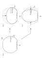
- FIG. 1 is a schematic configuration diagram showing an example of an interaction device according to an embodiment of the present invention. It is a schematic explanatory diagram showing the example of a modification of the interaction device concerning an embodiment of the present invention.
- FIG. 2 is a block diagram illustrating a configuration example of a circuit section of an interaction device according to an embodiment of the present invention.
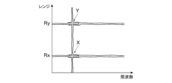
- FIG. 3 is an explanatory diagram showing an example of the output of a radar sensor processed by the interaction device according to the embodiment of the present invention.
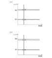
- FIG. 3 is an explanatory diagram showing an example of the output of a radar sensor in the interaction device according to the embodiment of the present invention.
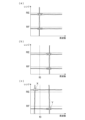
- FIG. 7 is another explanatory diagram showing an example of the output of the radar sensor in the interaction device according to the embodiment of the present invention.
- FIG. 7 is an explanatory diagram showing another example of arrangement of objects to be detected in the interaction device according to the embodiment of the present invention.
- FIG. 7 is another schematic explanatory diagram showing a modification of the interaction device according to the embodiment of the present invention
- an interaction device 1 includes a device main body 11, a radar sensor 12, and a circuit section 13, and connects an information processing device 2 to an information processing device wirelessly or by wire. is connected to enable communication between the two.
- FIG. 1 is a schematic perspective view showing an outline of an interaction device 1 according to an embodiment of the present invention, with a part of the exterior of the interaction device 1 being cut away to illustrate the inside thereof.
- the interaction device 1 is used by being placed on a surface such as a desk or the floor.
- the vertical direction of the device main body 11 of this interaction device 1 will be referred to as the Z axis, and the upper direction will be referred to as the positive direction.
- an X-axis and a Y-axis which are normal to this Z-axis and are orthogonal to the plane on which the device main body 11 is placed, are defined as shown in the figure.
- the X-axis is set in the transverse direction of the device main body 11, and the Y-axis is set in the front-rear direction of the device main body.
- the shape, size, ratio of each part, etc. of the interaction device 1 are merely examples, and other shapes, sizes, ratios of sizes of each part, etc. may differ from those exemplified. It doesn't matter if you stay there.
- the device main body 11 includes an exterior body 110 made of a deformable material.
- This exterior body 110 is made of a deformable material as described above.
- the exterior body 110 may be made of a polymer gel material such as a silicone polymer gel material, a urethane gel material, a polystyrene elastomer, an olefin elastomer, or a polyester material that is elastically deformable and can transmit the signal from the radar sensor 12. It can be constructed using various elastomer materials such as vinyl chloride elastomer, polyurethane elastomer, polyester elastomer, and polyamide elastomer.
- the exterior body 110 of the device main body 11 has a substantially hollow spherical shape. Furthermore, in one example of the present embodiment, a fabric such as fur, pile fabric, fake fur, or boa may be attached to the outer surface of the exterior body 110. These fabrics may be attached to the outside of the exterior body 110, or may be removable.
- a fabric such as fur, pile fabric, fake fur, or boa may be attached to the outer surface of the exterior body 110. These fabrics may be attached to the outside of the exterior body 110, or may be removable.
- the exterior body 110 of the device main body 11 has a predetermined shape, such as a spherical shape or a rectangular parallelepiped shape, in the absence of external force, and when the user applies an external force with a finger or the like, the shape changes according to the external force. shall be.
- a detection target object 111 whose position moves according to the deformation of the exterior body 110 is arranged inside the exterior body 110.
- the detection target object 111 may have a cantilever shape, for example, with its base 111b fixed to the inner surface of the exterior body 110 and protruding inward from the exterior body 110.
- the detection target object 111 similarly moves in the Z-axis direction (FIG. 2(b))
- the detection target object 111 similarly moves in the Z-axis direction (FIG. 2(c)).
- FIG. 2(a) shows the state of the exterior body 110 and the detection target object 111 in a natural state (no external force), and the broken lines in FIGS. The state in (a) is shown superimposed for comparison.
- the detection target object 111 is preferably detected at a predetermined distance from the surface of the exterior body 110 that faces the surface on which the radar sensor 12 is arranged (specifically, by the output of the radar sensor 12).
- the exterior body It may be arranged so as to be located below half of the height of the body 110.
- the detection target object 111 does not need to be directly fixed to the inner surface of the exterior body 110, but is attached to an elastic member attached to the exterior body 110 that transmits the deformation when the exterior body 110 is deformed.
- the base portion 111b may be fixed to a body (such as rubber or a spring).
- the radar sensor 12 is arranged on one side inside the exterior body 110.
- the example in FIG. 1 shows an example in which the radar sensor 12 is disposed on the inner bottom surface of the exterior body 110.
- this radar sensor 12 has a detection range R that is a predetermined range that includes the inside of the exterior body 110 from the surface on which the radar sensor 12 is disposed, and includes the outside of the surface of the exterior body 110 on the side opposite to the surface.
- a signal is emitted to the detection range R, the signal reflected by an object located within the detection range R is received, and the position of the object is detected.
- the detection range R of the radar sensor 12 is an inverted conical range (width becomes wider in the positive direction of the Z-axis) from the bottom of the exterior body 110.
- This detection range R includes a predetermined distance from the upper outer side of the exterior body 110, and also includes the detection target object 111.
- the radar sensor 12 is a pulse Doppler radar or an FMCW radar, and since the method of setting the detection range R as described above is widely known, a detailed explanation will be omitted here. do.
- the circuit section 13 includes a processor 131, a storage section 132, and a communication section 133, as illustrated in FIG. Each part of these circuit units 13 is operated by a battery (not shown).
- This battery may be a secondary battery that can be charged by, for example, a wireless power supply method or a wired power supply method.
- the processor 131 of the circuit section 13 includes a program control device such as a CPU, and operates according to a program stored in the storage section 132.
- this processor 131 receives the detection result of the target object from the radar sensor 12, and generates operation information that identifies the user's operation based on the accepted detection result. The operation of this processor 131 will be described later. Further, the processor 131 sends the generated operation information to the information processing device 2 via the communication unit 133.
- the storage unit 132 is, for example, a memory device, and holds programs executed by the processor 131. This storage unit 132 also operates as a work memory for the processor 131.
- the communication unit 133 is an interface for a wired communication method such as USB or a wireless communication method such as Bluetooth (registered trademark), and is connected to the information processing device 2 so as to be communicable by wired or wireless.
- the communication unit 133 sends information to the information processing device 2 according to instructions input from the processor 131.
- the communication unit 133 also outputs information received from the information processing device 2 to the processor 131.
- the radar sensor 12 obtains an IQ signal by multiplying a signal that is in phase with the repeatedly emitted signal and a signal that is 90° out of phase with the signal of the reflected wave, obtains the result of its Fourier transform (FFT), and further calculates the past number
- FFT Fourier transform
- a waterfall diagram exemplified in FIG. 4 is generated using the results of the Fourier transform for each batch.
- This waterfall diagram shows the detection results of the radar sensor 12 with frequency (Doppler velocity) on the horizontal axis and distance (Range) on the vertical axis. In the example of FIG. 4, the distance Rx, It is shown that detected objects X and Y are located in Ry and Ry respectively. Generation of such a waterfall diagram based on the signal output of the radar sensor 12 is widely known, so further detailed explanation will be omitted here.
- the processor 131 of the circuit unit 13 receives information on the detection results representing this waterfall diagram from the radar sensor 12. Based on this detection result, the processor 131 generates operation information, for example, as follows.
- the operation information generated by the processor 131 includes the state in which the user is bringing his hand close to the interaction device 1 of this embodiment, the state in which the user is touching the interaction device 1, and the state in which the user is touching the interaction device 1.
- a state in which the user is moving the hand while maintaining contact (a state in which the user is stroking the interaction device 1), a state in which the user is pressing the interaction device 1 in the vertical direction, and a state in which the user is pressing the interaction device 1 in the horizontal direction.
- the output of the radar sensor 12 is different from a predetermined distance RE, as illustrated in FIG. 5(a).
- the object in this case, the user's hand
- the object is detected far away, or the object is near a predetermined distance RE (the difference between the distance RE and the distance to the object is The object (in this case, the user's hand) can be identified based on whether the object (in this case, the user's hand) is detected (below a predetermined threshold).
- the Doppler velocity of an object farther away than the distance RE can be determined based on the Doppler velocity of an object farther away than the distance RE.
- the Doppler velocity of the object the user's hand
- the Doppler velocity of the object near the distance RE changes from when it was stationary. Whether you are simply touching or stroking can be determined from fluctuations in Doppler velocity.
- the distance RE represents the distance from the radar sensor 12 to the inner surface of the exterior body 110 when the exterior body 110 is not deformed.
- This distance RE is known.
- FIGS. 5A and 5B show that a detection target object 111 is being detected at a predetermined distance RF. When the exterior body 110 is not deformed, the distance RF from the radar sensor 12 to the detection target object 111 is also a known distance.
- the detection target object 111 is similarly pressed and moved to its initial position (distance from the radar sensor 12), as illustrated in FIG. 6(a).
- the radar sensor 12 moves closer to the bottom surface of the exterior body 110 than the RF position, and is detected at a distance from the radar sensor 12 that is shorter than that of the RF. Further, the distance between the inner surface of the exterior body 110 and the radar sensor 12 is also detected as being shorter than the distance RE.
- an object in this case, the user's hand
- the Doppler velocity of both objects is relatively high. (the frequency becomes higher than the stationary frequency f0).
- an object in this case, the user's hand
- an object in this case, the user's hand
- Another object is detected in a nearby position, but since the object is moving away from the radar sensor 12, the Doppler velocity becomes relatively small and it is detected. .
- the exterior body 110 stretches slightly in the vertical direction, and the distance between the inner surface of the exterior body 110 and the radar sensor 12 becomes longer than the distance RE.
- the detection target object 111 is similarly pressed in a direction that is farther away from or closer to the bottom side of the exterior body 110 than its initial position (the position at the distance RF from the radar sensor 12) (that direction is pressed against the position of the detection target object 111). RF), and the distance to the radar sensor 12 becomes longer or shorter than that of the RF.
- FIG. 6C shows a state in which the exterior body 110 is further extending in the Z-axis direction. Further, in this state, the target object (detection target object 111) is detected at a position farther than the distance RF and closer than the distance RE, or at a position closer than the distance RF (Y).
- FIG. 6(c) shows a state in which a target object (detection target object 111) is detected at a position closer than the distance RF and is further approaching the radar sensor 12.
- the processor 131 Every time the processor 131 receives a detection result from the radar sensor 12, the processor 131 performs the following based on the detection result: (1) When an object is detected at distance R, which is farther than distance RE, and when an object is detected at distance RF: the user's hand is nearby (the direction of movement can be determined by the Doppler velocity) ). (2) An object is detected within a predetermined distance range from distance RE, an object is detected at distance RF, and the Doppler velocity indicates that the object is stationary: A user is touching the interaction device 1. (3) An object is detected within a predetermined distance range from distance RE, an object is detected at distance RF, and the Doppler velocity indicates that the object is moving: A user is stroking the surface of the interaction device 1.
- the processor 131 outputs the operation information obtained by the judgment exemplified above to the communication unit 133 and causes it to be sent to the information processing device 2.
- the information processing device 2 uses the operation information received from the interaction device 1 to perform various processes. For example, when receiving operation information indicating that the user is pressing the interaction device 1 up or down, the information processing device 2 reduces the game character controlled by the user in the vertical direction, for example in the processing of a game application. Perform processing such as display.
- the interaction device 1 of the present embodiment may also include an actuator (not shown) such as a motor, drive the actuator according to instructions from the processor 131, and deform the exterior body 110 by the operation of the actuator.
- an actuator such as a motor
- a thread is formed on the outer periphery of a cylindrical body whose one end is adhered to the inner surface of the exterior body 110, and the thread of this cylindrical body is engaged with a ball screw rotationally driven by an actuator.
- the actuator rotates the ball screw, the cylindrical body moves along the longitudinal direction of the ball screw, and as a result, the exterior body 110 is pulled toward or pushed from the inside surface. 110 will be deformed.
- this is just an example, and other known methods may be used as long as the exterior body 110 can be deformed from the inner side according to instructions from the processor 131.
- the processor 131 when the processor 131 has such a mechanism for deforming the exterior body 110, each time it receives a detection result from the radar sensor 12, the processor 131 performs the operations (1) to (5) described above based on the detection result. In addition to being informed, (6) When there is no object near the distance RE, when an object (detection object 111 that moves due to the above deformation) is detected near the distance RF, and the processor 131 itself is instructing the deformation, the user It is determined that the transformation has occurred without any interaction with the It may also be a thing.
- the detection target object 111 disposed inside the exterior body 110 of the interaction device 1 is one, and has a cantilever shape that protrudes inward from the inner surface of the exterior body 110.
- the detection target object 111 may be configured as follows.
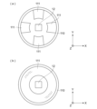
- the detection target objects 111 have a cantilever shape, and may be arranged in large numbers along the inner surface of the exterior body 110, as illustrated in FIG. 7(a). In this case, a plurality of detection target objects 111 may be arranged whose movement amounts differ from each other with respect to the deformation of the exterior body 110. Specifically, the detection target object 111 is attached directly to the inner surface of the exterior body 110, and the detection target object 111 is attached to the inner surface of the exterior body 110 via an elastic body such as hard rubber. Good too.
- the processor 131 detects the amount of movement of each detection target object 111, thereby making it possible to obtain the user's pressing force and the like in more detail.
- the detection target object 111 has a hollow disc shape or a hollow polygonal shape (the outer peripheral shape follows the inner surface shape of the exterior body 110), The outer periphery may be connected to the inner surface of the exterior body 110 directly or via an elastic body.
- FIG. 7 is a perspective view showing a state in which the exterior body 110 is cut along a plane parallel to its cross section (XY plane).
- the inside of the exterior body 110 may be filled with a filler material that is not detected by the radar sensor 12 (that is, fibers or the like that transmit waves transmitted by the radar).
- the filler material when the exterior body 110 is pressed and deformed, the filler material also deforms, making it easier for the detection target object 111 to move in accordance with the deformation of the exterior body 110.
- the detection target objects 111 to be detected by the radar sensor may be distributed in a dispersed manner. That is, in this example of the present embodiment, the object to be detected 111 is a powder or fibrous body such as a metal filler or a metal-coated filler that can be detected by the radar sensor 12, and is used by being mixed with the filler. They are distributed and arranged inside the exterior body 110.
- the detection target objects 111 are detected at various locations inside the exterior body 110, but when the exterior body 110 deforms, the detection target objects 111 dispersed inside the exterior body 110 move according to the deformation. and its dispersion range changes.
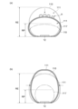
- the detection range of the detection target object 111 is dispersed into a range smaller than the distance RE, and its density increases, as illustrated in FIG. 8(a).
- the detection range of the detection target object 111 spreads and disperses to a range larger than the distance RE, and its density increases, as illustrated in FIG. 8(b).
- FIGS. 8A and 8B the initial detection range of the detection target object 111 (in a state where no pressing force is applied) and the shape of the exterior body 110 are shown by broken lines.
- the processor 131 can detect the user's operation based on the distribution range and density of the object corresponding to the detection target object 111, and can generate operation information representing the content of the detected operation.
- the detection target object 111 is uniformly distributed inside the exterior body 110
- the present embodiment is not limited to this.
- the dispersion density may be changed so that more particles are dispersed on the side closer to the target.
- a detection object such as a metal-coated filler unevenly dispersed in a filler is distinguished in the drawing as a detection object 111' (in the drawing, the dispersion range is indicated by a dashed line).
- the interior of the exterior body 110 is detected at a location relatively close to the radar sensor 12 (at a small distance).
- the detection range of the detection target object 111' changes from the initial dispersion range (in FIG. 8(a) to the distance RP), as illustrated in FIG. 8(a). range), and the density thereof becomes larger.
- the detection range of the detection target object 111' spreads and disperses to a range larger than the distance RP, and its density increases, as illustrated in FIG. 8(b). .
- the processor 131 can detect the user's operation based on the dispersion range and density of the object corresponding to the detection object 111', and can generate operation information representing the content of the detected operation.
- the object (the user's hand) H is also detected in a range close to the distance RE and closer to the radar sensor 12 than the distance RE. In this example of biasing the dispersion range of the detection target object 111, it becomes possible to distinguish and detect the user's hand and the detection target object 111'.
- the radar sensor 12 of the interaction device 1 of this embodiment may detect another interaction device 1 located outside the exterior body 110.
- the processor 131 in this example finds a part of the shape of the exterior body 110 of the interaction device 1 based on the detection result received from the radar sensor 12, or finds a part of the shape, and the communication unit 131 A predetermined process may be executed when close proximity communication with another interaction device 1 is possible via the interaction device 1 .
- the interaction devices 1 when the interaction devices 1 are arranged side by side, it is possible to perform operations such as emitting a predetermined sound, for example.
- Reference Signs List 1 interaction device 2 information processing device, 11 device main body, 12 radar sensor, 13 circuit section, 110 exterior body, 111 detection target object, 131 processor, 132 storage section, 133 communication section.
Landscapes
- Engineering & Computer Science (AREA)
- General Engineering & Computer Science (AREA)
- Theoretical Computer Science (AREA)
- Human Computer Interaction (AREA)
- Physics & Mathematics (AREA)
- General Physics & Mathematics (AREA)
- Radar Systems Or Details Thereof (AREA)
Abstract
Description
レーダーセンサ12は、繰り返し放射する信号と同相及び90°位相のずれた信号と、反射波の信号との乗算によりIQ信号を得て、そのフーリエ変換(FFT)の結果を得るとともに、さらに過去数回分のフーリエ変換の結果を用いて、図4に例示するウオーターフォール図を生成する。このウオーターフォール図は、横軸に周波数(ドップラー速度:Doppler Velocity)、縦軸に距離(Range)をとってレーダーセンサ12の検出結果を示したもので、図4の例では、距離Rxと、Ryとにそれぞれ検出された対象物X,Yが位置していることを示している。このような、レーダーセンサ12の信号出力に基づくウオーターフォール図の生成については広く知られているので、ここでのこれ以上の詳しい説明は省略する。
回路部13のプロセッサ131は、レーダーセンサ12から、このウオーターフォール図を表す検出結果の情報を受け入れる。プロセッサ131は、この検出結果に基づいて、例えば次のようにして、操作情報を生成する。
(1)距離REより遠方の距離Rに対象物を検出しており、かつ、距離RFに対象物を検出しているとき:ユーザの手が近くにある(その移動方向はドップラー速度によって判断できる)。
(2)距離REから予め定めた距離範囲に対象物を検出しており、かつ、距離RFに対象物を検出しており、ドップラー速度が、対象物が静止していることを表している:ユーザがインタラクション装置1に触れている。
(3)距離REから予め定めた距離範囲に対象物を検出しており、かつ、距離RFに対象物を検出しており、ドップラー速度が、対象物が移動していることを表している:ユーザがインタラクション装置1表面を撫でている。
(4)距離REより遠方の距離Rに対象物を検出しており、かつ、距離RFより近い位置で対象物を検出しており、ドップラー速度が、対象物が近接してきていることを表している:ユーザがインタラクション装置1を上下に押圧している。
(5)距離RE近傍に対象物がなく、距離RFより遠く、距離REより近い位置で対象物を検出しているとき:ユーザがインタラクション装置1を左右に押圧している。
のいずれかの操作情報を得る。
本実施の形態のインタラクション装置1は、また、モータなどのアクチュエータ(不図示)を備えて、プロセッサ131の指示によって当該アクチュエータを駆動し、当該アクチュエータの動作によって外装体110を変形させてもよい。一例として一端を外装体110の内面に接着した筒状体の外周にねじ山を形成し、この筒状体のねじ山をアクチュエータで回転駆動するボールねじに係合しておく。この例によると、アクチュエータがボールねじを回転させると、ボールねじの長手方向に沿って筒状体が移動し、それによって外装体110が内面に引かれたり内面から押されたりするので、外装体110が変形することとなる。もっともこれは一例であり、外装体110をプロセッサ131の指示によって内面側から変形できれば、他の公知の方法が採用されてもよい。
(6)距離RE近傍に対象物がなく、距離RF近傍で対象物(上記変形により移動する検出対象体111)を検知し、かつ、プロセッサ131自身が変形の指示を行っている場合に、ユーザとのインタラクションなしに変形ができていると判断する、
こととしてもよい。
ここまでの説明では、インタラクション装置1の外装体110内に配される検出対象体111は、一つであり、また外装体110の内面側から内方へ突出したカンチレバー形状であるものとしたが、これは一例であり、検出対象体111は、次のように構成されてもよい。
ここまでの説明では、距離REより遠方にある、つまり、外装体110より外側にある対象物としてユーザの体の一部(例えば手)を例として説明してきたが、本実施の形態において、距離REより遠方にある対象物は、ユーザの体の一部に限られない。
Claims (9)
- 変形可能な外装体と、
当該外装体の内側一方面側に配され、当該面から外装体内部を含み、当該面に対向する側の外装体表面より外側までの所定範囲を検出範囲として、当該検出範囲内での対象物の位置を検出するレーダーセンサと、
前記外装体の内側、前記検出範囲内に配され、前記外装体の変形に応じて移動する検出対象体と、をさらに備え、
前記レーダーセンサの検出結果が所定の処理に供されるインタラクション装置。 - 請求項1に記載のインタラクション装置であって、
前記レーダーセンサが配される内側一方面は前記外装体の底面部であり、前記検出範囲は、その上方の所定範囲であるインタラクション装置。 - 請求項1に記載のインタラクション装置であって、
前記レーダーセンサが配される内側一方面は前記外装体の底面部であり、前記検出範囲は、その上方の所定範囲であり、
前記検出対象体は、外装体内側へ突出した部分を有し、前記外装体の上側面から所定の距離だけ離れた位置に配されているインタラクション装置。 - 請求項3に記載のインタラクション装置であって、
前記検出対象体は、前記外装体の変形に応じて移動する基部から前記外装体内部に突出するカンチレバー形状を有しているインタラクション装置。 - 請求項1に記載のインタラクション装置であって、
前記外装体内部は、前記レーダーセンサにより検出されない充填材で充填されているインタラクション装置。 - 請求項5に記載のインタラクション装置であって、
前記充填材には、前記レーダーセンサにより検出される前記検出対象体が分散して配されているインタラクション装置。 - 請求項5に記載のインタラクション装置であって、
前記充填材には、前記レーダーセンサにより検出される前記検出対象体が分散して配され、当該検出対象体は、前記レーダーセンサから比較的離隔した側よりも前記レーダーセンサに比較的近接した側においてより多数分散されているインタラクション装置。 - 請求項1から4のいずれか一項に記載のインタラクション装置であって、
前記検出対象体を複数備えているインタラクション装置。 - 請求項1から7のいずれか一項に記載のインタラクション装置であって、
前記レーダーセンサは、前記検出対象体と、外装体外部に位置する物体とをそれぞれ対象物として検出するインタラクション装置。
Priority Applications (2)
| Application Number | Priority Date | Filing Date | Title |
|---|---|---|---|
| PCT/JP2022/029570 WO2024028962A1 (ja) | 2022-08-01 | 2022-08-01 | インタラクション装置 |
| US18/998,518 US20260044201A1 (en) | 2022-08-01 | 2022-08-01 | Interaction device |
Applications Claiming Priority (1)
| Application Number | Priority Date | Filing Date | Title |
|---|---|---|---|
| PCT/JP2022/029570 WO2024028962A1 (ja) | 2022-08-01 | 2022-08-01 | インタラクション装置 |
Publications (1)
| Publication Number | Publication Date |
|---|---|
| WO2024028962A1 true WO2024028962A1 (ja) | 2024-02-08 |
Family
ID=89848654
Family Applications (1)
| Application Number | Title | Priority Date | Filing Date |
|---|---|---|---|
| PCT/JP2022/029570 Ceased WO2024028962A1 (ja) | 2022-08-01 | 2022-08-01 | インタラクション装置 |
Country Status (2)
| Country | Link |
|---|---|
| US (1) | US20260044201A1 (ja) |
| WO (1) | WO2024028962A1 (ja) |
Citations (6)
| Publication number | Priority date | Publication date | Assignee | Title |
|---|---|---|---|---|
| JPH11312040A (ja) * | 1998-01-12 | 1999-11-09 | Xerox Corp | コンピュ―タユ―ザインタフェ―ス及びコンピュ―タ |
| JP2005339088A (ja) * | 2004-05-26 | 2005-12-08 | Hori Co Ltd | 球体型入力装置 |
| JP2012027541A (ja) * | 2010-07-20 | 2012-02-09 | Sony Corp | 接触圧検知装置および入力装置 |
| WO2012079948A1 (en) * | 2010-12-16 | 2012-06-21 | International Business Machines Corporation | A human interface device with two three-axis-accelerometers |
| WO2017169641A1 (ja) * | 2016-03-29 | 2017-10-05 | 株式会社齋藤創造研究所 | 入力装置および画像表示システム |
| CN112068696A (zh) * | 2020-08-28 | 2020-12-11 | 深圳晶泰科技有限公司 | Vr头盔、晶体交互系统及方法 |
Family Cites Families (2)
| Publication number | Priority date | Publication date | Assignee | Title |
|---|---|---|---|---|
| DE102017111208A1 (de) * | 2017-05-23 | 2018-11-29 | Innogy Se | Ladeeinheit mit Anzeigevorrichtung |
| US11740065B2 (en) * | 2021-08-06 | 2023-08-29 | Toyota Research Institute, Inc. | Deformable sensors and methods for modifying run-time membrane stiffness using magnetic attraction |
-
2022
- 2022-08-01 US US18/998,518 patent/US20260044201A1/en active Pending
- 2022-08-01 WO PCT/JP2022/029570 patent/WO2024028962A1/ja not_active Ceased
Patent Citations (6)
| Publication number | Priority date | Publication date | Assignee | Title |
|---|---|---|---|---|
| JPH11312040A (ja) * | 1998-01-12 | 1999-11-09 | Xerox Corp | コンピュ―タユ―ザインタフェ―ス及びコンピュ―タ |
| JP2005339088A (ja) * | 2004-05-26 | 2005-12-08 | Hori Co Ltd | 球体型入力装置 |
| JP2012027541A (ja) * | 2010-07-20 | 2012-02-09 | Sony Corp | 接触圧検知装置および入力装置 |
| WO2012079948A1 (en) * | 2010-12-16 | 2012-06-21 | International Business Machines Corporation | A human interface device with two three-axis-accelerometers |
| WO2017169641A1 (ja) * | 2016-03-29 | 2017-10-05 | 株式会社齋藤創造研究所 | 入力装置および画像表示システム |
| CN112068696A (zh) * | 2020-08-28 | 2020-12-11 | 深圳晶泰科技有限公司 | Vr头盔、晶体交互系统及方法 |
Also Published As
| Publication number | Publication date |
|---|---|
| US20260044201A1 (en) | 2026-02-12 |
Similar Documents
| Publication | Publication Date | Title |
|---|---|---|
| US9304587B2 (en) | Force sensing mouse | |
| US7084854B1 (en) | Actuator for providing tactile sensations and device for directional tactile sensations | |
| US10268270B2 (en) | System and method for shape deformation and force display of devices | |
| EP2778852B1 (en) | Programmable haptic peripheral | |
| US8677838B2 (en) | Contact-pressure detecting apparatus and input apparatus | |
| US9715278B2 (en) | User interface device provided with surface haptic sensations | |
| JP6411756B2 (ja) | 接触子に基づいたハプティックフィードバック生成 | |
| US20200391112A1 (en) | Information processing program | |
| EP3489803A1 (en) | Systems and methods for providing haptic feedback according to tilt-based inputs | |
| US10241577B2 (en) | Single actuator haptic effects | |
| US20120144076A1 (en) | Mobile device and computational system including same | |
| EP1927916A1 (en) | Apparatus, method, and medium for outputting tactile feedback on display device | |
| US20020084982A1 (en) | Haptic sensations for tactile feedback interface devices | |
| KR101873402B1 (ko) | 3자유도 촉각 전달 장치 및 방법 | |
| US8957768B2 (en) | Operation apparatus | |
| KR20170026567A (ko) | 3차원 콘텍스트 피드백 | |
| CN102446025A (zh) | 基于物理模型的手势识别 | |
| KR20170061071A (ko) | 증폭된 변형을 위해 구성된 변형 가능 기판을 구비한 햅틱 주변 장치 | |
| US20130027294A1 (en) | Input apparatus, input method, and control system | |
| JP2019153272A (ja) | 入力装置 | |
| JP2020011050A (ja) | 触覚コントローラのためのトリガ・ボタン | |
| JP2019096312A (ja) | 触覚アクセサリー装置 | |
| JP2019109889A (ja) | 二次元及び三次元追跡に使用可能な触覚有効周辺機器 | |
| CN105677028A (zh) | 一种控制方法、电子设备及电子装置 | |
| US20260044201A1 (en) | Interaction device |
Legal Events
| Date | Code | Title | Description |
|---|---|---|---|
| 121 | Ep: the epo has been informed by wipo that ep was designated in this application |
Ref document number: 22953951 Country of ref document: EP Kind code of ref document: A1 |
|
| WWE | Wipo information: entry into national phase |
Ref document number: 18998518 Country of ref document: US |
|
| NENP | Non-entry into the national phase |
Ref country code: DE |
|
| 122 | Ep: pct application non-entry in european phase |
Ref document number: 22953951 Country of ref document: EP Kind code of ref document: A1 |
|
| NENP | Non-entry into the national phase |
Ref country code: JP |
|
| WWP | Wipo information: published in national office |
Ref document number: 18998518 Country of ref document: US |