WO2024023934A1 - ワーク取出し装置、ワーク取出し方法及び制御装置 - Google Patents
ワーク取出し装置、ワーク取出し方法及び制御装置 Download PDFInfo
- Publication number
- WO2024023934A1 WO2024023934A1 PCT/JP2022/028805 JP2022028805W WO2024023934A1 WO 2024023934 A1 WO2024023934 A1 WO 2024023934A1 JP 2022028805 W JP2022028805 W JP 2022028805W WO 2024023934 A1 WO2024023934 A1 WO 2024023934A1
- Authority
- WO
- WIPO (PCT)
- Prior art keywords
- hand
- workpiece
- container
- take
- posture
- Prior art date
- Legal status (The legal status is an assumption and is not a legal conclusion. Google has not performed a legal analysis and makes no representation as to the accuracy of the status listed.)
- Ceased
Links
Images
Classifications
-
- B—PERFORMING OPERATIONS; TRANSPORTING
- B65—CONVEYING; PACKING; STORING; HANDLING THIN OR FILAMENTARY MATERIAL
- B65G—TRANSPORT OR STORAGE DEVICES, e.g. CONVEYORS FOR LOADING OR TIPPING, SHOP CONVEYOR SYSTEMS OR PNEUMATIC TUBE CONVEYORS
- B65G47/00—Article or material-handling devices associated with conveyors; Methods employing such devices
- B65G47/74—Feeding, transfer, or discharging devices of particular kinds or types
- B65G47/90—Devices for picking-up and depositing articles or materials
- B65G47/905—Control arrangements
-
- B—PERFORMING OPERATIONS; TRANSPORTING
- B25—HAND TOOLS; PORTABLE POWER-DRIVEN TOOLS; MANIPULATORS
- B25J—MANIPULATORS; CHAMBERS PROVIDED WITH MANIPULATION DEVICES
- B25J9/00—Program-controlled manipulators
- B25J9/16—Program controls
- B25J9/1612—Program controls characterised by the hand, wrist, grip control
-
- B—PERFORMING OPERATIONS; TRANSPORTING
- B25—HAND TOOLS; PORTABLE POWER-DRIVEN TOOLS; MANIPULATORS
- B25J—MANIPULATORS; CHAMBERS PROVIDED WITH MANIPULATION DEVICES
- B25J9/00—Program-controlled manipulators
- B25J9/16—Program controls
- B25J9/1694—Program controls characterised by use of sensors other than normal servo-feedback from position, speed or acceleration sensors, perception control, multi-sensor controlled systems, sensor fusion
- B25J9/1697—Vision controlled systems
-
- G—PHYSICS
- G05—CONTROLLING; REGULATING
- G05B—CONTROL OR REGULATING SYSTEMS IN GENERAL; FUNCTIONAL ELEMENTS OF SUCH SYSTEMS; MONITORING OR TESTING ARRANGEMENTS FOR SUCH SYSTEMS OR ELEMENTS
- G05B2219/00—Program-control systems
- G05B2219/30—Nc systems
- G05B2219/40—Robotics, robotics mapping to robotics vision
- G05B2219/40053—Pick 3-D object from pile of objects
-
- G—PHYSICS
- G05—CONTROLLING; REGULATING
- G05B—CONTROL OR REGULATING SYSTEMS IN GENERAL; FUNCTIONAL ELEMENTS OF SUCH SYSTEMS; MONITORING OR TESTING ARRANGEMENTS FOR SUCH SYSTEMS OR ELEMENTS
- G05B2219/00—Program-control systems
- G05B2219/30—Nc systems
- G05B2219/45—Nc applications
- G05B2219/45063—Pick and place manipulator
Definitions
- Embodiments of the present invention relate to a workpiece retrieval device, a workpiece retrieval method, and a control device.
- Patent Document 3 there are known article retrieval devices that can recognize the position and orientation of bulk articles and take out the articles without performing pattern matching using various three-dimensional measuring machines.
- One aspect of the present disclosure includes a robot equipped with a hand that takes out a workpiece in a container, a shape setting unit that sets shapes of the hand, the container, and the workpiece, and a shape setting unit configured to detect the container and the workpiece in the container.
- a sensor configured to take out a detected workpiece, a takeout position/attitude determining unit that determines a takeout position and takeout attitude of the hand when the detected workpiece is taken out by the hand; is located above and inside the container, and a relay position determining unit that determines a relay position where the hand is in the take-out position; and an operation control unit that moves the hand from the relay position to the take-out position by only translational movement.
- It is a workpiece retrieval device comprising: and a part.
- Another aspect of the present disclosure is a workpiece retrieval method using a robot equipped with a hand for retrieving a workpiece in a container, the method comprising: setting the shapes of the hand, the container, and the workpiece; detecting a workpiece in the workpiece, determining the takeout position and takeout posture of the hand when taking out the detected workpiece with the hand; and determining the takeout position and takeout posture of the hand when the hand takes out the detected workpiece; determining a relay position located above and inside a container and at which the posture of the hand becomes the take-out position; and moving the hand from the relay position to the take-out position by only translational movement.
- This is the extraction method.
- Still another aspect of the present disclosure is a robot equipped with a hand that takes out a workpiece in a container, and a sensor control device configured to detect the container and the workpiece, the control device for a sensor configured to detect the hand, the container, and the workpiece.
- a shape setting unit that sets a shape
- a take-out position and posture determining unit that determines a take-out position and a take-out attitude of the hand when taking out the detected workpiece with the hand
- a relay position determination unit that determines a relay position where the hand is located above and inside the container and the posture of the hand becomes the take-out position
- a relay position determination unit that moves the hand from the relay position to the take-out position by only translational movement.
- a control device includes an operation control section.
- the relay position is above and inside the container, and furthermore, the hand does not change its posture after the relay position, and approaches the extraction target only by translational movement. Therefore, an efficient take-out operation can be performed without causing the hand to interfere with the container or other workpieces.
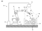
- FIG. 1 is a schematic configuration diagram of a workpiece retrieval device according to an embodiment.
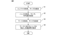
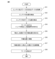
- 3 is a flowchart illustrating an example of processing at the time of setting. 7 is a flowchart illustrating an example of processing at the time of execution of retrieval.
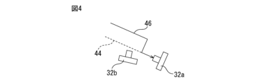
- FIG. 3 is a schematic diagram showing an example of a moving path of a hand.
- FIG. 1 is a schematic configuration diagram of a workpiece take-out device according to a preferred embodiment.
- the workpiece retrieval device 10 includes at least one robot 12, a three-dimensional vision sensor 14, and a control device 16 that is connected to the robot 12 and the sensor 14 by wire or wirelessly and controls the robot 12 and the sensor 14.
- the robot 12 is, for example, an industrial vertical articulated robot with a serial link structure, and includes a base 18 installed at a predetermined location such as a production line in a factory, a rotating body 20 rotatably attached to the base 18, and a rotating body. a first arm (upper arm) 22 rotatably attached to the first arm 20; a second arm (forearm) 24 rotatably attached to the first arm 22; It has a freely attached wrist part (mechanical interface) 26 and a robot hand 28 attached to the wrist part 26, and is configured to take out works 32 randomly loaded in a container 30 one by one. There is.
- the three-dimensional sensor 14 is configured to detect the position of the container 30 and the workpiece 32 within the container 30 based on a command from the control device 16, and is configured to detect the position of the container 30 and the workpiece 32 within the container 30, for example, using two two-dimensional cameras. It is possible to use a stereo camera that detects a three-dimensional position based on the parallax captured by an image, a TOF (Time of Flight) camera that captures a distance image using a time-of-flight method, and the like.
- TOF Time of Flight
- the robot 12 is configured to be able to perform various tasks such as taking out a workpiece based on commands sent from the control device 16.
- the control device 16 includes a processor and a storage unit (memory, etc.), and can control the container 30 and the sensor 14 that detects the workpiece 32 in the container 30 in addition to controlling the robot 12 .
- the processor of the robot control device 16 has a shape setting section that sets the shapes of the hand 28, the container 30, and the workpiece 32, and the takeout position and takeout position of the hand 28 when taking out the detected workpiece 32 with the hand 28.
- a take-out position/attitude determination unit that determines the posture and a relay position (described later) where the hand 28 is above and inside the container 30 and the posture of the hand 28 is the take-out posture when performing the operation of taking out the detected workpiece 32. It has the functions of a relay position determination unit that determines the relay position, and an operation control unit that moves the hand 28 from the relay position to the take-out position by only translational movement.
- a computer such as a personal computer (PC) that is connected to the control device 16 by wire or wirelessly and has a processor and a storage unit (memory, etc.) can operate the robot.
- An operation program or the like may be generated and the generated program or the like may be transmitted from the computer to the control device 16.
- FIG. 2 is a flowchart showing an example of a process performed as a setting before the workpiece 32 is actually taken out by the workpiece takeout device 10.
- step S1 the shape and size of the container 30 in which the works 32 are to be stacked in bulk are set.
- step S2 the shape, size, and position of representative points such as the tool tip point (TCP) of the robot hand 28 are set.
- TCP tool tip point
- step S3 the shape and size of the workpiece 32 are set.
- step S4 the take-out position and attitude of the hand 28 with respect to the work 32, that is, the position and attitude of the hand 28 with respect to the work 32 when the hand 28 takes out the work 32 are set.
- the settings in steps S1 to S4 may be made by the user via an input unit (not shown) such as an appropriate user interface, or may be made by the control device 14 or other devices based on the 3D model of the container, hand, workpiece, etc.
- the processor of the computer may perform this automatically.
- FIG. 3 is a flowchart showing an example of a process when the workpiece 32 is taken out by the workpiece takeout device 10.
- step S11 three-dimensional data of the container 30 and the workpiece 32 inside the container 30 is acquired.
- the sensor 14 is used to acquire image data or a three-dimensional point group of the container 30 and the workpiece 32.
- step S12 the position of the container 30 is detected. Specifically, the position of the container 30 is determined based on a method such as model matching using the three-dimensional data of the container 30 acquired in step S11 and the shape and size of the container 30 set in step S1 described above. .
- step S13 the position of the work 32 within the container 30 is detected. Specifically, similar to step S12, based on a method such as model matching using the three-dimensional data of the workpiece 32 acquired in step S11 and the shape and size of the workpiece 32 set in step S3 above, Find the position of the workpiece 32. At this time, the posture of the workpiece 32 can also be determined.
- step S14 the take-out position and orientation of the hand 28 with respect to the workpiece 32 is determined. Specifically, the position of the hand 28 when taking out the detected workpiece 32 is based on the position (or position and orientation) of the workpiece 32 detected in step S13 and the hand takeout position and orientation set in step S4 described above. Find the take-out position and take-out posture.
- a relay position that the hand 28 should pass through before reaching the extraction position determined in step S14 is determined.
- the relay position is a position that the hand 28 (its representative point, etc.) must pass through before reaching the workpiece 32 to be taken out, and at the relay position, the hand 28 assumes the above-mentioned taking out posture. is located above and inside the container 30.
- “above the container” means a space above the upper end 38 of the container 30 in the vertical direction as shown in FIG. 1, and “inside the container” as shown by reference numeral 40 in FIG. This means the space obtained by sweeping the opening of the container 30 vertically upward.
- a specific method for calculating the relay position is, for example, to use CAD data of the hand 28 to determine whether there is interference between the hand 28 and the container 30 or workpiece 32.
- CAD data of the hand 28 to determine whether there is interference between the hand 28 and the container 30 or workpiece 32.
- CAD data to determine whether there is interference between the hand 28 and the container 30 or workpiece 32.
- the calculation process may take time.
- the shape of the hand 28 is approximated to a basic shape that includes at least one of a sphere, a cylinder, a polygonal prism, and a polyhedron, and the entire basic shape is positioned above and inside the container 30.
- the relay position may also be determined.
- a convex hull (convex polyhedron) containing the hand 28 may be determined from the CAD data of the hand 28, and the relay position may be determined such that each vertex of the convex hull is located above and inside the container 30. In either case, calculation time can be significantly reduced compared to using CAD data as is.
- step S15 it may not be possible to calculate or determine a relay position that satisfies the above-mentioned condition (the relay position is above and inside the container) for the work to be taken out. In this case, it can be determined that there was a problem as to which workpiece should be taken out, so it is preferable not to perform the work to take out the workpiece that was targeted to be taken out, but to restart the work with another workpiece to be taken out.
- step S16 the hand 28 is moved to the relay position determined in step S15.
- the robot 12 is controlled so that the hand 28 assumes the take-out posture determined in step S14 by the time the hand 28 reaches the relay position.
- the hand 28 assumes the take-out posture determined in step S14 by the time the hand 28 reaches the relay position.
- the robot 12 is controlled so that the hand 28 assumes the take-out posture determined in step S14 by the time the hand 28 reaches the relay position.
- the robot 12 is controlled so that the hand 28 assumes the take-out posture determined in step S14 by the time the hand 28 reaches the relay position.
- the approach direction of the hand 28 to the workpiece 32 to be taken out is the z direction of the coordinate system 34 set for the workpiece 32
- the hand 28 moves to the coordinate system set for the hand 28 at the relay position.
- the extraction posture is such that the z-direction of the system 36 is parallel to the z-direction of the coordinate system 34.
- step S17 the hand 28 is translated (parallel movement) from the relay position to the workpiece take-out position.
- the hand 28 moves along a movement path 42 from the relay position to the workpiece 32 to be taken out without changing its posture.
- the movement path from the relay position to the workpiece to be taken out may be a simple straight line, may include straight lines in different directions connected by at least one bending point as shown in FIG. 1, or may include at least a partially curved line. May include.
- step S18 the workpiece 32 to be taken out is taken out by gripping or suctioning with the hand 28.
- steps S11 to S18 described above are repeated.
- FIG. 4 is a schematic diagram illustrating an example of a process for determining a relay position. If the workpiece 32a is detected as the object to be taken out, and the relay position is determined so that the hand 28 moves along one straight line (movement path) 44 from the relay position to the workpiece 32a, another workpiece 32b will be moved by the hand. There is a possibility of interference with 28. On the other hand, in order to take out the workpiece 32a, the hand 28 needs to move along the straight line 44 at least in the vicinity of the workpiece 32a.
- the relay position is The target workpiece 32a can be taken out while reliably avoiding interference with the workpiece 32b.
- the relay position is above and inside the container 30, and the hand 28 does not change its posture after the relay position, and approaches the object to be taken out only by translational movement. Therefore, the hand 28 can perform a smooth takeout operation without interfering with the container 30 or other workpieces 32.
Landscapes
- Engineering & Computer Science (AREA)
- Mechanical Engineering (AREA)
- Robotics (AREA)
- Health & Medical Sciences (AREA)
- General Health & Medical Sciences (AREA)
- Orthopedic Medicine & Surgery (AREA)
- Manipulator (AREA)
Abstract
Description
12 ロボット
14 センサ
16 制御装置
28 ロボットハンド
30 コンテナ
32、32a、32b ワーク
42、44、46 移動経路
Claims (7)
- コンテナ内のワークを取出すハンドを搭載したロボットと、
前記ハンド、前記コンテナ及び前記ワークの形状を設定する形状設定部と、
前記コンテナ及び前記コンテナ内のワークを検出するように構成されたセンサと、
検出されたワークを前記ハンドで取り出すときの前記ハンドの取出し位置及び取出し姿勢を求める取出し位置姿勢決定部と、
前記検出されたワークを取出す動作を行う際に、前記ハンドが前記コンテナの上方かつ内側にあり、前記ハンドの姿勢が前記取出し姿勢となる中継位置を決定する中継位置決定部と、
前記ハンドを前記中継位置から並進移動のみで前記取出し位置に移動させる動作制御部と、
を備える、ワーク取出し装置。 - 前記中継位置決定部は、前記ハンドの形状を、球、円柱、多角柱及び多面体の少なくとも1つを含む基本形状に近似し、該基本形状の全体が前記コンテナの上方かつ内側に位置するように中継位置を決定する、請求項1に記載のワーク取出し装置。
- 前記中継位置決定部は、前記ハンドを内包する凸包を求め、該凸包の各頂点が前記コンテナの上方かつ内側に位置するように中継位置を決定する、請求項1に記載のワーク取出し装置。
- 前記動作制御部は、前記中継位置が前記コンテナの上方かつ内側に設定することができない場合は、前記検出されたワークの取出し動作は行わないように前記ロボットを制御する、請求項1に記載のワーク取出し装置。
- 前記中継位置決定部は、前記検出されたワークから一定距離離れた移動経路の一部を上方に変位させた移動経路に沿って前記ハンドが移動するように中継位置を決定する、請求項1に記載のワーク取出し装置。
- コンテナ内のワークを取出すハンドを搭載したロボットを用いたワーク取出し方法であって、
前記ハンド、前記コンテナ及び前記ワークの形状を設定することと、
前記コンテナ及び前記コンテナ内のワークを検出することと、
検出されたワークを前記ハンドで取り出すときの前記ハンドの取出し位置及び取出し姿勢を求めることと、
前記検出されたワークを取出す動作を行う際に、前記ハンドが前記コンテナの上方かつ内側にあり、前記ハンドの姿勢が前記取出し姿勢となる中継位置を決定することと、
前記ハンドを前記中継位置から並進移動のみで前記取出し位置に移動させることと、
を含む、ワーク取出し方法。 - コンテナ内のワークを取出すハンドを搭載したロボット、並びに前記コンテナ及び前記ワークを検出するように構成されたセンサの制御装置であって、
前記ハンド、コンテナ及びワークの形状を設定する形状設定部と、
検出されたワークを前記ハンドで取り出すときの前記ハンドの取出し位置及び取出し姿勢を求める取出し位置姿勢決定部と、
前記検出されたワークを取出す動作を行う際に、前記ハンドが前記コンテナの上方かつ内側にあり、前記ハンドの姿勢が前記取出し姿勢となる中継位置を決定する中継位置決定部と、
前記ハンドを前記中継位置から並進移動のみで前記取出し位置に移動させる動作制御部と、
を備える、制御装置。
Priority Applications (6)
| Application Number | Priority Date | Filing Date | Title |
|---|---|---|---|
| DE112022007254.7T DE112022007254T5 (de) | 2022-07-26 | 2022-07-26 | Werkstück-entnahmevorrichtung, werkstück-entnahmeverfahren und steuervorrichtung |
| JP2024536600A JPWO2024023934A1 (ja) | 2022-07-26 | 2022-07-26 | |
| PCT/JP2022/028805 WO2024023934A1 (ja) | 2022-07-26 | 2022-07-26 | ワーク取出し装置、ワーク取出し方法及び制御装置 |
| US18/880,665 US20260001728A1 (en) | 2022-07-26 | 2022-07-26 | Workpiece removal device, workpiece removal method, and control device |
| CN202280098123.6A CN119451786A (zh) | 2022-07-26 | 2022-07-26 | 工件取出装置、工件取出方法以及控制装置 |
| TW112125701A TW202419237A (zh) | 2022-07-26 | 2023-07-10 | 工件取出裝置、工件取出方法及控制裝置 |
Applications Claiming Priority (1)
| Application Number | Priority Date | Filing Date | Title |
|---|---|---|---|
| PCT/JP2022/028805 WO2024023934A1 (ja) | 2022-07-26 | 2022-07-26 | ワーク取出し装置、ワーク取出し方法及び制御装置 |
Publications (1)
| Publication Number | Publication Date |
|---|---|
| WO2024023934A1 true WO2024023934A1 (ja) | 2024-02-01 |
Family
ID=89705642
Family Applications (1)
| Application Number | Title | Priority Date | Filing Date |
|---|---|---|---|
| PCT/JP2022/028805 Ceased WO2024023934A1 (ja) | 2022-07-26 | 2022-07-26 | ワーク取出し装置、ワーク取出し方法及び制御装置 |
Country Status (6)
| Country | Link |
|---|---|
| US (1) | US20260001728A1 (ja) |
| JP (1) | JPWO2024023934A1 (ja) |
| CN (1) | CN119451786A (ja) |
| DE (1) | DE112022007254T5 (ja) |
| TW (1) | TW202419237A (ja) |
| WO (1) | WO2024023934A1 (ja) |
Citations (2)
| Publication number | Priority date | Publication date | Assignee | Title |
|---|---|---|---|---|
| WO2012066819A1 (ja) * | 2010-11-17 | 2012-05-24 | 三菱電機株式会社 | ワーク取り出し装置 |
| JP2015205368A (ja) * | 2014-04-21 | 2015-11-19 | キヤノン株式会社 | 部品ピッキング方法、ロボット装置、プログラム及び記録媒体 |
Family Cites Families (3)
| Publication number | Priority date | Publication date | Assignee | Title |
|---|---|---|---|---|
| JP3842233B2 (ja) | 2003-03-25 | 2006-11-08 | ファナック株式会社 | 画像処理装置及びロボットシステム |
| JP5480667B2 (ja) | 2010-02-26 | 2014-04-23 | キヤノン株式会社 | 位置姿勢計測装置、位置姿勢計測方法、プログラム |
| JP2015089590A (ja) | 2013-11-05 | 2015-05-11 | ファナック株式会社 | バラ積みされた物品をロボットで取出す装置及び方法 |
-
2022
- 2022-07-26 JP JP2024536600A patent/JPWO2024023934A1/ja active Pending
- 2022-07-26 WO PCT/JP2022/028805 patent/WO2024023934A1/ja not_active Ceased
- 2022-07-26 US US18/880,665 patent/US20260001728A1/en active Pending
- 2022-07-26 DE DE112022007254.7T patent/DE112022007254T5/de active Pending
- 2022-07-26 CN CN202280098123.6A patent/CN119451786A/zh active Pending
-
2023
- 2023-07-10 TW TW112125701A patent/TW202419237A/zh unknown
Patent Citations (2)
| Publication number | Priority date | Publication date | Assignee | Title |
|---|---|---|---|---|
| WO2012066819A1 (ja) * | 2010-11-17 | 2012-05-24 | 三菱電機株式会社 | ワーク取り出し装置 |
| JP2015205368A (ja) * | 2014-04-21 | 2015-11-19 | キヤノン株式会社 | 部品ピッキング方法、ロボット装置、プログラム及び記録媒体 |
Also Published As
| Publication number | Publication date |
|---|---|
| CN119451786A (zh) | 2025-02-14 |
| TW202419237A (zh) | 2024-05-16 |
| JPWO2024023934A1 (ja) | 2024-02-01 |
| DE112022007254T5 (de) | 2025-03-06 |
| US20260001728A1 (en) | 2026-01-01 |
Similar Documents
| Publication | Publication Date | Title |
|---|---|---|
| CN113696186B (zh) | 复杂光照条件下基于视触融合的机械臂自主移动抓取方法 | |
| EP3383593B1 (en) | Teaching an industrial robot to pick parts | |
| US11090814B2 (en) | Robot control method | |
| JP7275759B2 (ja) | 物体検出方法、物体検出装置およびロボットシステム | |
| EP3392002A1 (en) | Information processing apparatus, measuring apparatus, system, interference determination method, and article manufacturing method | |
| CN112512754B (zh) | 对工业机器人编程的方法 | |
| EP3222393B1 (en) | Automated guidance system and method for a coordinated movement machine | |
| JP5620445B2 (ja) | 選択条件に基づいてロボットの保持位置姿勢を決定する物品取出装置 | |
| JP2019188580A (ja) | 情報処理装置、制御方法、ロボットシステム、コンピュータプログラム、及び記憶媒体 | |
| JP2018161692A (ja) | 情報処理装置、情報処理方法およびプログラム | |
| JP2018176334A5 (ja) | ||
| JP2014161965A (ja) | 物品取り出し装置 | |
| JP5458807B2 (ja) | 対象物把持領域抽出装置および対象物把持領域抽出装置を用いたロボットシステム | |
| CN115003464A (zh) | 机器人系统 | |
| JP2022160363A (ja) | ロボットシステム、制御方法、画像処理装置、画像処理方法、物品の製造方法、プログラム、及び記録媒体 | |
| US20180215044A1 (en) | Image processing device, robot control device, and robot | |
| WO2021117479A1 (ja) | 情報処理装置、方法およびプログラム | |
| JP7708840B2 (ja) | ロボットの構成部材の干渉を検出するロボット装置 | |
| JP7614326B2 (ja) | 教示工具または作業者の手を用いて教示点を設定する教示装置 | |
| CN110871443A (zh) | 物品取出系统 | |
| WO2024023934A1 (ja) | ワーク取出し装置、ワーク取出し方法及び制御装置 | |
| WO2021210514A1 (ja) | ロボットの制御装置及び制御方法、ロボットシステム、ロボットの動作プログラムを生成する装置及び方法 | |
| JP7286524B2 (ja) | ピッキングロボット、ピッキング方法及びプログラム | |
| WO2023243051A1 (ja) | ワーク取り出しシステム | |
| CN116457161B (zh) | 信息处理装置及拣选装置 |
Legal Events
| Date | Code | Title | Description |
|---|---|---|---|
| 121 | Ep: the epo has been informed by wipo that ep was designated in this application |
Ref document number: 22953031 Country of ref document: EP Kind code of ref document: A1 |
|
| ENP | Entry into the national phase |
Ref document number: 2024536600 Country of ref document: JP Kind code of ref document: A |
|
| WWE | Wipo information: entry into national phase |
Ref document number: 18880665 Country of ref document: US |
|
| WWE | Wipo information: entry into national phase |
Ref document number: 202280098123.6 Country of ref document: CN |
|
| WWE | Wipo information: entry into national phase |
Ref document number: 112022007254 Country of ref document: DE |
|
| WWP | Wipo information: published in national office |
Ref document number: 202280098123.6 Country of ref document: CN |
|
| WWP | Wipo information: published in national office |
Ref document number: 112022007254 Country of ref document: DE |
|
| 122 | Ep: pct application non-entry in european phase |
Ref document number: 22953031 Country of ref document: EP Kind code of ref document: A1 |
|
| WWP | Wipo information: published in national office |
Ref document number: 18880665 Country of ref document: US |