WO2024019031A1 - 作業支援システム - Google Patents
作業支援システム Download PDFInfo
- Publication number
- WO2024019031A1 WO2024019031A1 PCT/JP2023/026189 JP2023026189W WO2024019031A1 WO 2024019031 A1 WO2024019031 A1 WO 2024019031A1 JP 2023026189 W JP2023026189 W JP 2023026189W WO 2024019031 A1 WO2024019031 A1 WO 2024019031A1
- Authority
- WO
- WIPO (PCT)
- Prior art keywords
- height
- removal plate
- earth removal
- work
- information
- Prior art date
- Legal status (The legal status is an assumption and is not a legal conclusion. Google has not performed a legal analysis and makes no representation as to the accuracy of the status listed.)
- Ceased
Links
Images


Classifications
-
- E—FIXED CONSTRUCTIONS
- E02—HYDRAULIC ENGINEERING; FOUNDATIONS; SOIL SHIFTING
- E02F—DREDGING; SOIL-SHIFTING
- E02F3/00—Dredgers; Soil-shifting machines
- E02F3/04—Dredgers; Soil-shifting machines mechanically-driven
- E02F3/76—Graders, bulldozers, or the like with scraper plates or ploughshare-like elements; Levelling scarifying devices
- E02F3/80—Component parts
- E02F3/815—Blades; Levelling or scarifying tools
-
- E—FIXED CONSTRUCTIONS
- E02—HYDRAULIC ENGINEERING; FOUNDATIONS; SOIL SHIFTING
- E02F—DREDGING; SOIL-SHIFTING
- E02F9/00—Component parts of dredgers or soil-shifting machines, not restricted to one of the kinds covered by groups E02F3/00 - E02F7/00
- E02F9/20—Drives; Control devices
Definitions
- the present invention relates to a work support system, and can be applied to work machines such as hydraulic excavators, for example.
- machine guidance is a technology that supports the operation of a work machine using measurement technology such as a total station (TS) or a global navigation satellite system (GNSS). According to this machine guidance, it is possible to appropriately support operator operations and improve work efficiency, safety, and work accuracy.
- TS total station
- GNSS global navigation satellite system
- Such ICT construction machinery places sensors on the movable parts of the working machine, and creates information (hereinafter referred to as support information as appropriate) that supports operator operations based on the detection results of these sensors.
- support information information that supports operator operations based on the detection results of these sensors.
- Patent Document 1 Patent Document 1
- Patent Document 2 discloses a device related to such an earth removal plate.
- the leveling work may be temporarily interrupted to change the height of the earth removal plate (the height of the lower end of the earth removal plate from the target leveling surface). Specifically, this is the case when various obstacles are present on the route, when the work location needs to be changed, etc.
- the height of the earth removal plate can be set to the original height at the time of interruption of the work, and the earth leveling work can be resumed with the originally planned target level of land leveling.
- the present invention has been made in consideration of the above points, and when the leveling work is temporarily interrupted and the height of the earth removal plate is changed, the height of the earth removal plate is changed to the original height at the time of interruption of the work.
- the purpose is to make it easy to set up.
- the invention of claim 1 In the work support system that supports the operations of the operator who operates the work machine, a detection device that is held on the earth removal plate of the working machine and that acquires and outputs posture information of the earth removal plate using a sensor; a controller that is held in the main body of the work machine and that acquires and sends posture information of the earth removal plate; a portable information terminal device that acquires the posture information sent from the controller, detects the height of the earth removal plate, and outputs support information; and a notification device that notifies the operator of the support information
- the mobile information terminal device includes: When the height of the earth removal plate changes from the height of the earth removal plate on the land leveling target surface, the support information indicates that the height of the earth removal plate is different from the height of the earth removal plate on the land leveling target surface. This is notified via the notification device.
- the height of the soil removal plate is detected by acquiring the posture information sent from the controller with the portable information terminal device, and the detected height of the soil removal plate is determined based on the leveling target surface.
- the height of the earth removal plate changes from the height of the earth removal plate at If the height of the earth removal plate is changed after interruption, the operator is notified by the notification device that the height of the earth removal plate has returned to the original height, which is the height of the earth removal plate on the target leveling surface. This can be easily confirmed. As a result, the height of the earth removal plate can be easily set to the original height at the time the work was interrupted.
- the invention of claim 2 has the structure of claim 1,
- the mobile information terminal device includes: After the height of the earth removal plate changes from the height of the earth removal plate on the land leveling target surface, when the height of the earth earth removal plate reaches the height of the earth earth removal plate on the land leveling target surface, the notification device Notify via.
- the height of the earth removal plate can be easily set to the original height at the time of interruption of the work.
- FIG. 1 is a diagram showing a work support system according to a first embodiment of the present invention.
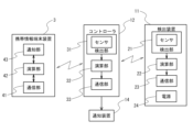
- 2 is a block diagram of the work support system of FIG. 1.
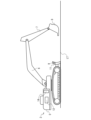
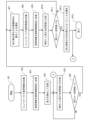
- FIG. It is a figure used for explanation of the ground leveling work. It is a figure which shows the state where the height of the earth removal board changed. It is a flowchart which shows the processing procedure regarding the notification of the height of an earth removal board.
- FIG. 1 is a diagram showing a work support system 1 according to a first embodiment of the present invention
- FIG. 2 is a block diagram.
- This work support system 1 includes a hydraulic excavator 2, which is a working machine, and a mobile information terminal device 3, and supports the operations of an operator who operates the hydraulic excavator 2 through a machine guidance function.
- the hydraulic excavator 2 has a main body 5 so as to be self-propelled on an endless track, and a boom 6 is rotatably provided on the main body 5. Further, in the hydraulic excavator 2, an arm 7 is rotatably provided at the tip of the boom 6, and a bucket 8 is further rotatably provided at the tip of the arm 7. Further, in the hydraulic excavator 2, a soil removal plate 9 is provided on the main body 5 so as to move up and down with respect to the main body 5 by rotation by a rotation shaft (not shown).
- the work support system 1 is not limited to hydraulic excavators, but can be widely applied to various types of work machines used in civil engineering and construction work, such as work machines used for ground improvement, for example.
- the hydraulic excavator 2 includes a detection device 11, a controller 12, and a notification device 14.
- a detection device 11 is provided on the earth removal plate 9. Note that the detection device 11 may be provided directly on the earth removal plate 9, or may be provided on a movable part (stay) that moves in conjunction with the vertical movement of the earth removal plate 9.
- the detection device 11 includes a detection section 21, a calculation section 22, a communication section 23, and a power source 24, and acquires and outputs posture information of the earth removal plate 9 using a sensor.
- the detection unit 21 includes a sensor, which acquires and outputs three-dimensional acceleration information and angular velocity information.
- an IMU INERTIAL MEASUREMENT UNIT
- a sensor other than three axes may be applied, and the posture information
- Various configurations capable of detecting can be widely applied.
- the calculation unit 22 processes the measurement results by the sensor output from the detection unit 21 using a built-in calculation processing circuit, and acquires posture information indicating the posture of the earth removal plate 9.
- the communication unit 23 sends the posture information acquired by the calculation unit 22 to the controller 12 through data communication via wireless communication.
- BLUETOOTH registered trademark
- a wide range of wireless communication capable of data communication can be applied.
- the power supply 24 outputs battery power to the detection section 21, the calculation section 22, and the communication section 23.
- the detection device 11 can be easily installed at a desired installation location without providing cables for power supply or data communication.
- machine guidance functions can be easily introduced into existing work machines, and machine guidance functions can also be improved.
- the controller 12 is provided in the main body 5 of the hydraulic excavator 2, and acquires posture information of the main body 5 using a sensor. Furthermore, the controller 12 acquires the attitude information of the earth removal plate 9, and sends the attitude information of the earth removal plate 9 and the attitude information of the main body 5 through data communication using wireless communication. Furthermore, the controller 12 receives support information through wireless data communication and displays it on the notification device 14. For this purpose, the controller 12 includes a detection section 31, a calculation section 32, and a communication section 33.
- the detection unit 31 has the same configuration as the detection unit 21 of the detection device 11, and outputs acceleration information and angular velocity information of the main body 5.
- the communication unit 33 sends and receives various data to and from the detection device 11 and the mobile information terminal device 3 by wireless data communication.
- the arithmetic unit 32 controls the operation of each unit by executing a control program related to the controller 12 using a built-in arithmetic processing circuit.
- the calculation unit 32 processes the measurement results by the sensor output from the detection unit 31 and acquires the attitude information of the main body 5 according to the instruction from the mobile information terminal device 3, and also acquires the attitude information from the detection device 11. . Further, this attitude information is sent to the mobile information terminal device 3 through data communication via wireless communication. It also receives support information sent from the mobile information terminal device 3 and displays this support information on the notification device 14. Note that the detection unit 31 may be omitted if it is sufficient for practical purposes.
- the notification device 14 is provided in the driver's seat of the hydraulic excavator 2, displays support information provided by the controller 12, and thereby notifies the operator of the support information. More specifically, the notification device 14 is formed by an image display panel such as a liquid crystal display panel, and notifies support information using image information. Note that the notification device 14 may notify support information for supporting the operator's operations by voice or alarm sound, or may use a combination of these.
- the mobile information terminal device 3 is a so-called smartphone or tablet terminal carried by the operator, generates support information based on posture information obtained from the controller 12, and sends the generated support information to the controller 12.
- the mobile information terminal device 3 includes a communication section 41, a calculation section 42, and a notification section 43.
- the notification section 43 is formed by an image display panel such as a liquid crystal display panel, and displays various image information and support information related to the portable information terminal device 3.
- the notification unit 43 may notify support information for supporting the operator's operations by voice or alarm sound, or may use a combination of these.
- the communication unit 41 transmits and receives various data to and from the controller 12 through wireless data communication, and furthermore, connects to a network and transmits, for example, programs related to the processing of this work support system 1. Perform version upgrades, etc.
- the calculation unit 42 acquires posture information from the controller 12 by executing the control program of the work support system 1 using a built-in calculation processing circuit, and processes this posture information to generate support information. The information is sent to the controller 12 and the notification section 43.
- the portable information terminal device 3 receives the setting of the target leveling surface LT for the land to be leveled by the calculation unit 42, as shown in FIG.
- the setting of the target land leveling surface LT is executed by varying the height of the earth removal plate 9 by an operator's operation based on, for example, measurement results by a support staff member.
- the operator can move the hydraulic excavator 2 forward to push the earth and sand forward with the earth removal plate 9 and level the ground at the target leveling surface LT.
- the ground leveling work is temporarily suspended and the height H of the earth removal plate 9 is increased to avoid the obstacles as shown in Fig. 4. Thereafter, the height of the earth removal plate 9 is set to the original height at the time when the work was interrupted, and the ground leveling work is restarted.
- the work location may be changed, and in this case as well, the ground leveling work is temporarily suspended, the height H of the earth removal plate 9 is raised, and after moving to the next work area, the height of the earth removal plate 9 is increased.
- the leveling work will be resumed with the level set to the original height at the time of interruption.
- you temporarily stop the leveling work and change the height of the earth removal plate you can easily set the height of the earth removal plate to the original height at the time of interruption, which will further improve work efficiency. Improved ability to perform land leveling work quickly.
- the mobile information terminal device 3 detects the height H of the earth removal plate 9 from the posture information of the earth removal plate 9 obtained via the controller 12, and while monitoring the height H of the earth removal plate 9, the earth removal plate 9 is removed.
- the height H of the earth removal plate 9 changes from the height H of the earth removal plate 9 at the target land leveling surface LT
- the height H of the earth removal plate 9 changes from the height H of the earth removal plate 9 at the land leveling target surface LT based on the support information. It is notified via the notification device 14 that the information is different from the above.
- the notification device 14 will notify the operator that the height H of the earth removal plate 9 will be changed to the earth removal plate at the earth leveling target surface LT. It can be easily confirmed that the earth removal plate 9 has returned to its original height, which is the height H, and the height H of the soil removal plate 9 can be easily set to the original height at the time when the work was interrupted.
- the mobile information terminal device 3 detects the height H of the earth removal plate 9 from the posture information of the earth removal plate 9 obtained via the controller 12 at the start of the earth leveling work, thereby determining the earth leveling target surface.
- the height H of the earth removal plate 9 at LT is detected, and the height H of the earth removal plate 9 at this leveling target surface LT is stored.
- the mobile information terminal device 3 starts the ground leveling work, sequentially detects the height H of the earth removal plate 9 from the posture information of the earth removal plate 9 obtained via the controller 12, and determines the height H of the earth removal plate 9.
- the change in the height H of the earth removal plate 9 from the height H of the earth removal plate on the earth leveling target surface LT is detected by comparing it with the height H of the earth removal plate 9 on the land leveling target surface LT stored and held as H. do. In order to prevent erroneous detection due to vibrations during ground leveling work, this change is detected using a certain threshold value A.
- the mobile information terminal device 3 detects the height H of the earth removal plate 9 and the height H of the earth removal plate 9 at the target land leveling surface LT. Support information is generated based on the difference value, and based on this difference value, a notification is sent via the notification device 14 that the height H of the earth removal board 9 is different from the height H of the earth removal board 9 on the land leveling target surface LT.
- various notification methods can be applied to this notification, for example, it may be performed by a segment display using an LED, a blinking display, and furthermore, it may be performed by a text display, an alarm sound, or a voice.
- the height of the earth removal plate 9 may be detected using only the attitude information of the earth removal plate 9, or may be performed using the attitude information of the earth removal plate 9 and the attitude information of the main body 5. You can also do this.
- the height H of the earth removal plate 9 changes from the height of the earth removal plate 9 at the target land leveling surface LT
- the height H of the earth removal plate 9 changes from the height H of the earth removal plate 9 at the land leveling target surface LT.
- a notification is sent via the notification device 14.
- the height H of the earth removal plate 9 is sequentially detected from the posture information of the earth removal plate 9 obtained via the controller 12, and the height H of the earth removal plate 9 is determined as the height H of the earth removal plate 9 at the stored leveling target surface LT.
- this notification can be performed by switching the display on the notification device 14, for example, it may be performed by segment display using LEDs, blinking display, etc. Furthermore, it may be executed by text display, alarm sound, or voice. For example, when the height H of the soil removal plate 9 changes, a notification is given by an image display, and when the height H returns to the original height H, a notification is given by audio or alarm sound. By using a notification method different from that used when the height H of the earth removal plate 9 changes, the operator can immediately determine what state the earth removal plate height is in.
- FIG. 5 is a flowchart showing a processing procedure related to notification of the height H of the earth removal board 9 in this earth leveling work.
- the controller 12 collects posture information from the detection device 11 and the detection unit 31 under the control of the mobile information terminal device 3 (SP2), and the collected posture information is transmitted from the controller 12. It is sent to the mobile information terminal device 3 (SP3). Further, in the portable information terminal device 3, the height H of the earth removal plate 9 is detected and stored from the posture information, and thereby the height H of the earth removal plate 9 on the target land leveling surface LT is stored (SP4).
- the posture information from the detection device 11 and the detection unit 31 is acquired by the mobile information terminal device 3 via the controller 12, and the height H of the earth removal plate 9 is detected by the mobile information terminal device 3. , compared with the stored value (SP5). If the subtraction value obtained by subtracting the stored value (height H of the earth removal plate 9 at the target leveling surface LT) from the height H detected here is less than the threshold value A, the height H of the earth removal plate 9 has not changed. As a result, the process returns to step SP5 (SP6).
- the controller 12 collects posture information from the detection device 11 and the detection unit 31 (SP8), and sends the collected posture information from the controller 12 to the mobile information terminal device 3 (SP9). Further, the height H of the earth removal plate 9 is detected by the portable information terminal device 3 and compared with a stored value (SP10). If the subtracted value obtained by subtracting the stored value from the height H detected here is greater than or equal to the threshold value B, the height H of the soil removal plate 9 has not returned to the original height, and the process returns to step SP7 (SP11).
- the height of the soil removal plate is detected by acquiring the posture information sent from the controller with the mobile information terminal device, and the detected height of the soil removal plate is determined by the height of the soil removal plate on the land leveling target surface.
- the support information notifies you via the notification device that the height of the soil removal plate is different from the height of the soil removal plate on the target leveling surface, and temporarily suspends the soil leveling work.
- a change in height H is detected by directly comparing height H with a stored value
- the present invention is not limited to this.
- a change in the height H may be detected by comparing the values.
- the determination of whether the height has returned to the original height may be performed by indirectly comparing the height H by comparing the posture information.
Landscapes
- Engineering & Computer Science (AREA)
- Mining & Mineral Resources (AREA)
- Civil Engineering (AREA)
- General Engineering & Computer Science (AREA)
- Structural Engineering (AREA)
- Mechanical Engineering (AREA)
- Component Parts Of Construction Machinery (AREA)
- Operation Control Of Excavators (AREA)
Abstract
整地作業を一時中断して、排土板の高さを変更する場合、排土板の高さを作業中断時点の元の高さに簡易に設定することができるようにする。 作業機械2を操作するオペレータの操作を支援する作業支援システム1において、作業機械2の排土板9に保持されて、センサにより排土板9の姿勢情報を取得して出力する検出装置11と、作業機械2の本体5に保持されて、排土板9の姿勢情報を取得して送出するコントローラ12と、コントローラ12から送出された姿勢情報を取得して排土板9の高さを検出して支援情報を出力する携帯情報端末装置3と、支援情報をオペレータに通知する通知装置14とを備える。携帯情報端末装置3は、排土板9の高さが整地目標面における排土板9の高さから変化すると、支援情報により排土板9の高さが整地目標面における排土板9の高さと異なっていることを通知装置14を介して通知する。
Description
本発明は、作業支援システムに関し、例えば油圧ショベル等の作業機械に適用することができる。
従来、マシンガイダンスの機能を組み込んだ作業機械(作業支援システムを適用した作業機械であり、いわゆるICT建機である)が提供されている。
ここでマシンガイダンスは、トータルステーション(TS:Total Station)、GNSS(Global Navigation Satellite System)等の計測技術を利用して作業機械の操作を支援する技術である。このマシンガイダンスによれば、オペレータの操作を適切に支援して、作業効率、安全性、作業精度を向上することができる。
ここでマシンガイダンスは、トータルステーション(TS:Total Station)、GNSS(Global Navigation Satellite System)等の計測技術を利用して作業機械の操作を支援する技術である。このマシンガイダンスによれば、オペレータの操作を適切に支援して、作業効率、安全性、作業精度を向上することができる。
このようなICT建機は、作業機械の可動部にセンサを配置し、このセンサによる検出結果に基づいてオペレータの操作を支援する情報(以下、適宜、支援情報と呼ぶ)を作成している(例えば特許文献1)。
また従来、油圧ショベルを利用する作業現場では、油圧ショベルに設けられた排土板により整地作業を実行している。特許文献2には、このような排土板に関する工夫が開示されている。
ところで整地作業では、整地作業を一時中断して、排土板の高さ(整地目標面から排土板下端の高さ)を変更する場合がある。具体的には、各種の障害物が進路上に存在する場合、作業箇所を変更する場合等である。
このように一時中断した作業を再開する場合、排土板の高さを作業中断時点の元の高さに設定して、当初予定した整地目標面により整地作業を再開することができる。
このように一時中断した作業を再開する場合、排土板の高さを作業中断時点の元の高さに設定して、当初予定した整地目標面により整地作業を再開することができる。
しかしながら運転席から排土板を目視できない場合もあり、整地作業を一時中断して排土板の高さを変更する場合、排土板の高さを作業中断時点の元の高さに簡易に設定することが困難な問題があった。因みに排土板の高さを作業中断時点の元の高さに簡易に設定することができれば、一段と作業効率を向上して、迅速に整地作業を実行することができる。
本発明は以上の点を考慮してなされたものであり、整地作業を一時中断して、排土板の高さを変更する場合、排土板の高さを作業中断時点の元の高さに簡易に設定することができるようにすることを目的とする。
係る課題を解決するため、請求項1の発明は、
作業機械を操作するオペレータの操作を支援する作業支援システムにおいて、
前記作業機械の排土板に保持されて、センサにより前記排土板の姿勢情報を取得して出力する検出装置と、
前記作業機械の本体に保持されて、前記排土板の姿勢情報を取得して送出するコントローラと、
前記コントローラから送出された前記姿勢情報を取得して前記排土板の高さを検出して支援情報を出力する携帯情報端末装置と、
前記オペレータに前記支援情報を通知する通知装置とを備え、
前記携帯情報端末装置は、
前記排土板の高さが整地目標面における前記排土板の高さから変化すると、前記支援情報により前記排土板の高さが前記整地目標面における前記排土板の高さと異なっていることを前記通知装置を介して通知する。
作業機械を操作するオペレータの操作を支援する作業支援システムにおいて、
前記作業機械の排土板に保持されて、センサにより前記排土板の姿勢情報を取得して出力する検出装置と、
前記作業機械の本体に保持されて、前記排土板の姿勢情報を取得して送出するコントローラと、
前記コントローラから送出された前記姿勢情報を取得して前記排土板の高さを検出して支援情報を出力する携帯情報端末装置と、
前記オペレータに前記支援情報を通知する通知装置とを備え、
前記携帯情報端末装置は、
前記排土板の高さが整地目標面における前記排土板の高さから変化すると、前記支援情報により前記排土板の高さが前記整地目標面における前記排土板の高さと異なっていることを前記通知装置を介して通知する。
請求項1の構成によれば、コントローラから送出された姿勢情報を携帯情報端末装置で取得して排土板の高さを検出するようにして、検出した排土板の高さが整地目標面における排土板の高さから変化すると、支援情報により排土板の高さが整地目標面における排土板の高さと異なっていることを通知装置を介して通知することにより、整地作業を一時中断して、排土板の高さを変更する場合、オペレータにおいては、通知装置による通知により排土板の高さが整地目標面における排土板の高さである元の高さに戻ったことを容易に確認することができる。これにより排土板の高さを作業中断時点の元の高さに簡易に設定することができる。
請求項2の発明は、請求項1の構成において、
前記携帯情報端末装置は、
前記排土板の高さが整地目標面における前記排土板の高さから変化した後、前記排土板の高さが前記整地目標面における前記排土板の高さになると、前記通知装置を介して通知する。
前記携帯情報端末装置は、
前記排土板の高さが整地目標面における前記排土板の高さから変化した後、前記排土板の高さが前記整地目標面における前記排土板の高さになると、前記通知装置を介して通知する。
請求項2の構成によれば、排土板の高さが整地目標面における排土板の高さから変化した後、排土板の高さが整地目標面における排土板の高さになると、通知装置を介して通知することにより、排土板の高さが元の高さに戻ったことを容易に確認することができる。
本発明によれば、整地作業を一時中断して、排土板の高さを変更する場合、排土板の高さを作業中断時点の元の高さに簡易に設定することができる。
〔第1実施形態〕
図1は、本発明の第1実施形態に係る作業支援システム1を示す図であり、図2は、ブロック図である。
この作業支援システム1は、作業機械である油圧ショベル2、携帯情報端末装置3を備え、マシンガイダンスの機能により油圧ショベル2を操作するオペレータの操作を支援する。
図1は、本発明の第1実施形態に係る作業支援システム1を示す図であり、図2は、ブロック図である。
この作業支援システム1は、作業機械である油圧ショベル2、携帯情報端末装置3を備え、マシンガイダンスの機能により油圧ショベル2を操作するオペレータの操作を支援する。
油圧ショベル2は、無限軌道により自走するように本体5が形成され、この本体5に回動自在にブーム6が設けられる。さらに油圧ショベル2は、このブーム6の先端に回動自在にアーム7が設けられ、さらにアーム7の先端に回動自在にバケット8が設けられる。
さらに油圧ショベル2は、図示しない回動軸による回動により本体5に対して上下動するように、排土板9が本体5に設けられる。なお作業支援システム1は、油圧ショベルに限らず、例えば地盤改良に使用する作業機械等、土木、建築の作業に使用される各種作業機械に広く適用することができる。
さらに油圧ショベル2は、図示しない回動軸による回動により本体5に対して上下動するように、排土板9が本体5に設けられる。なお作業支援システム1は、油圧ショベルに限らず、例えば地盤改良に使用する作業機械等、土木、建築の作業に使用される各種作業機械に広く適用することができる。
油圧ショベル2は、検出装置11、コントローラ12、通知装置14を備える。油圧ショベル2は、排土板9に検出装置11が設けられる。なお検出装置11は、排土板9に直接設けるようにしてもよく、排土板9の上下動に連動して可動する可動部(ステー)に設けるようにしてもよい。
検出装置11は、検出部21、演算部22、通信部23、電源24を備え、センサにより排土板9の姿勢情報を取得して出力する。
検出部21は、センサを備え、このセンサにより3次元の加速度情報、角速度情報を取得して出力する。
ここでこの実施形態において、検出部21のセンサには、IMU(INERTIAL MEASUREMENT UNIT)センサが適用されるものの、IMUセンサに限らず、3軸以外のセンサを適用するようにしてもよく、姿勢情報を検出可能な種々の構成を広く適用することができる。
検出部21は、センサを備え、このセンサにより3次元の加速度情報、角速度情報を取得して出力する。
ここでこの実施形態において、検出部21のセンサには、IMU(INERTIAL MEASUREMENT UNIT)センサが適用されるものの、IMUセンサに限らず、3軸以外のセンサを適用するようにしてもよく、姿勢情報を検出可能な種々の構成を広く適用することができる。
演算部22は、内臓の演算処理回路により検出部21から出力されるセンサによる計測結果を処理し、排土板9の姿勢を示す姿勢情報を取得する。
通信部23は、演算部22で取得された姿勢情報を、無線通信によるデータ通信によりコントローラ12に送出する。この通信部23における無線通信には、BLUETOOTH(登録商標)が適用されるものの、データ通信可能な無線通信を広く適用することができる。
電源24は、バッテリの電力を検出部21、演算部22、通信部23に出力する。このようにバッテリの電力により動作して無線通信により姿勢情報を送出することにより、検出装置11は、電源供給用、データ通信用のケーブルを設けることなく、所望する取り付け箇所に簡易に設置することができ、これにより簡易に既存の作業機械にマシンガイダンスの機能を導入することができ、さらにはマシンガイダンスの機能を向上することができる.
コントローラ12は、油圧ショベル2の本体5に設けられ、センサにより本体5の姿勢情報を取得する。さらにコントローラ12は、排土板9の姿勢情報を取得し、排土板9の姿勢情報と本体5の姿勢情報とを無線通信によるデータ通信により送出する。さらにコントローラ12は、無線通信によるデータ通信により支援情報を受信して通知装置14により表示する。このためコントローラ12は、検出部31、演算部32、通信部33を備える。
検出部31は、検出装置11の検出部21と同一に構成され、本体5の加速度情報、角速度情報を出力する。
通信部33は、無線通信によるデータ通信により検出装置11及び携帯情報端末装置3との間で種々のデータを送受する。
通信部33は、無線通信によるデータ通信により検出装置11及び携帯情報端末装置3との間で種々のデータを送受する。
演算部32は、内臓の演算処理回路によりコントローラ12に係る制御プログラムを実行することにより、各部の動作を制御する。これにより演算部32は、携帯情報端末装置3の指示により、検出部31から出力されるセンサによる計測結果を処理して本体5の姿勢情報を取得すると共に、検出装置11から姿勢情報を取得する。またこれらの姿勢情報を無線通信によるデータ通信により携帯情報端末装置3に送出する。また携帯情報端末装置3から送出される支援情報を受信し、この支援情報を通知装置14で表示する。
なお実用上十分な場合、検出部31を省略するようにしてもよい。
なお実用上十分な場合、検出部31を省略するようにしてもよい。
通知装置14は、油圧ショベル2の運転席に設けられ、コントローラ12による支援情報を表示し、これにより支援情報をオペレータに通知する。より具体的に、通知装置14は、液晶表示パネル等の画像表示パネルにより形成され、画像情報により支援情報を通知する。なお通知装置14は、音声、警報音によりオペレータの操作を支援する支援情報を通知するようにしてもよく、これらを組み合わせるようにしてもよい.
携帯情報端末装置3は、オペレータの携帯するいわゆるスマートフォンやタブレット端末であり、コントローラ12より得られる姿勢情報により支援情報を生成し、この生成した支援情報をコントローラ12に送出する。
より具体的に、携帯情報端末装置3は、通信部41、演算部42、通知部43を備える。
ここで通知部43は、液晶表示パネル等の画像表示パネルにより形成され、この携帯情報端末装置3に係る各種の画像情報及び支援情報を表示する。なお通知部43は、音声、警報音によりオペレータの操作を支援する支援情報を通知するようにしてもよく、これらを組み合わせるようにしてもよい.
通信部41は、演算部42の制御により、無線通信によるデータ通信によりコントローラ12との間で種々のデータを送受し、さらにはネットワークに接続して例えばこの作業支援システム1の処理に係るプログラムのバージョンアップ等を実行する。
ここで通知部43は、液晶表示パネル等の画像表示パネルにより形成され、この携帯情報端末装置3に係る各種の画像情報及び支援情報を表示する。なお通知部43は、音声、警報音によりオペレータの操作を支援する支援情報を通知するようにしてもよく、これらを組み合わせるようにしてもよい.
通信部41は、演算部42の制御により、無線通信によるデータ通信によりコントローラ12との間で種々のデータを送受し、さらにはネットワークに接続して例えばこの作業支援システム1の処理に係るプログラムのバージョンアップ等を実行する。
演算部42は、内臓の演算処理回路によりこの作業支援システム1の制御プログラムを実行することにより、コントローラ12から姿勢情報を取得すると共に、この姿勢情報を処理して支援情報を生成し、この支援情報をコントローラ12及び通知部43に送出する。
〔整地処理〕
携帯情報端末装置3は、オペレータによる指示により、図3に示すように、整地する土地について、演算部42により整地目標面LTの設定を受け付ける。なお整地目標面LTの設定は、例えばサポート要員による計測結果に基づいてオペレータの操作により排土板9の高さを可変して実行される。これによりオペレータにおいては、油圧ショベル2を前方に走行させることにより、排土板9で土砂を押し進んで、整地目標面LTで整地することができる。
携帯情報端末装置3は、オペレータによる指示により、図3に示すように、整地する土地について、演算部42により整地目標面LTの設定を受け付ける。なお整地目標面LTの設定は、例えばサポート要員による計測結果に基づいてオペレータの操作により排土板9の高さを可変して実行される。これによりオペレータにおいては、油圧ショベル2を前方に走行させることにより、排土板9で土砂を押し進んで、整地目標面LTで整地することができる。
しかしながら進路上に岩等の障害物が存在する場合があり、この場合、整地作業を一時中断して、図4に示すように排土板9の高さHを高くして障害物を避け、その後、排土板9の高さを作業中断時点の元の高さに設定して整地作業を再開することになる。また作業箇所を変更する場合もあり、この場合も整地作業を一時中断して、排土板9の高さHを高くして続く作業箇所まで移動した後、排土板9の高さを作業中断時点の元の高さに設定して整地作業を再開することになる。
これにより整地作業を一時中断して、排土板の高さを変更する場合、排土板の高さを作業中断時点の元の高さに簡易に設定できるようにすれば、一段と作業効率を向上して、迅速に整地作業を実行することができる。
これにより整地作業を一時中断して、排土板の高さを変更する場合、排土板の高さを作業中断時点の元の高さに簡易に設定できるようにすれば、一段と作業効率を向上して、迅速に整地作業を実行することができる。
そこで携帯情報端末装置3は、コントローラ12を介して得られる排土板9の姿勢情報から排土板9の高さHを検出して、排土板9の高さHをモニタしながら、排土板9の高さHが整地目標面LTにおける排土板9の高さHから変化すると、支援情報により排土板9の高さHが整地目標面LTにおける排土板9の高さHと異なっていることを通知装置14を介して通知する。
これによりオペレータにおいては、整地作業を一時中断して、排土板9の高さHを変更する場合、通知装置14による通知により排土板9の高さHが整地目標面LTにおける排土板9の高さHである元の高さに戻ったことを容易に確認することができ、排土板9の高さHを作業中断時点の元の高さに簡易に設定することができる。
これによりオペレータにおいては、整地作業を一時中断して、排土板9の高さHを変更する場合、通知装置14による通知により排土板9の高さHが整地目標面LTにおける排土板9の高さHである元の高さに戻ったことを容易に確認することができ、排土板9の高さHを作業中断時点の元の高さに簡易に設定することができる。
より具体的に、携帯情報端末装置3は、整地作業の開始時、コントローラ12を介して得られる排土板9の姿勢情報から排土板9の高さHを検出することにより、整地目標面LTにおける排土板9の高さHを検出し、この整地目標面LTにおける排土板9の高さHを記憶する。
携帯情報端末装置3は、整地作業を開始して、コントローラ12を介して得られる排土板9の姿勢情報から排土板9の高さHを順次検出し、この排土板9の高さHと記憶して保持した整地目標面LTにおける排土板9の高さHと比較し、整地目標面LTにおける排土板の高さHからの排土板9の高さHの変化を検出する。なお整地作業中の振動による誤検出を防止するために、この変化の検出は、一定の閾値Aにより判定して実行する。
携帯情報端末装置3は、整地作業を開始して、コントローラ12を介して得られる排土板9の姿勢情報から排土板9の高さHを順次検出し、この排土板9の高さHと記憶して保持した整地目標面LTにおける排土板9の高さHと比較し、整地目標面LTにおける排土板の高さHからの排土板9の高さHの変化を検出する。なお整地作業中の振動による誤検出を防止するために、この変化の検出は、一定の閾値Aにより判定して実行する。
携帯情報端末装置3は、このようにして排土板9の高さHの変化が検出されると、排土板9の高さHと整地目標面LTにおける排土板9の高さHとの差分値により支援情報を生成し、この差分値により排土板9の高さHが整地目標面LTにおける排土板9の高さHと異なっていることを通知装置14を介して通知する。
なおこの通知にあっては、種々の通知方法を適用することができ、例えばLEDによるセグメント表示、点滅表示により実行しても良く、さらにはテキスト表示、警報音、音声により実行しても良い。
また排土板9の高さの検出にあっては、排土板9の姿勢情報のみにより実行するようにしてもよく、排土板9の姿勢情報と本体5の姿勢情報とにより実行するようにしてもよい。
なおこの通知にあっては、種々の通知方法を適用することができ、例えばLEDによるセグメント表示、点滅表示により実行しても良く、さらにはテキスト表示、警報音、音声により実行しても良い。
また排土板9の高さの検出にあっては、排土板9の姿勢情報のみにより実行するようにしてもよく、排土板9の姿勢情報と本体5の姿勢情報とにより実行するようにしてもよい。
さらにこのようにして排土板9の高さHが整地目標面LTにおける排土板9の高さから変化した後、排土板9高さHが整地目標面LTにおける排土板9の高さHになると、通知装置14を介して通知する。
すなわちコントローラ12を介して得られる排土板9の姿勢情報から排土板9の高さHを順次検出し、この排土板9の高さHと記憶して保持した整地目標面LTにおける排土板9の高さHと比較し、これにより排土板9高さHが整地目標面LTにおける排土板9の高さHとなったことを検出する。
なおこの場合、一定の閾値B(B<A)により判定して排土板9高さHが整地目標面LTにおける排土板9の高さHとなったことを検出する。
すなわちコントローラ12を介して得られる排土板9の姿勢情報から排土板9の高さHを順次検出し、この排土板9の高さHと記憶して保持した整地目標面LTにおける排土板9の高さHと比較し、これにより排土板9高さHが整地目標面LTにおける排土板9の高さHとなったことを検出する。
なおこの場合、一定の閾値B(B<A)により判定して排土板9高さHが整地目標面LTにおける排土板9の高さHとなったことを検出する。
これによりオペレータにおいては、排土板9の高さHが元の高さに戻ったことを容易に確認することができ、負担を軽減することができる。
ここでこの通知にあっては、種々の手法を適用することができ、通知装置14の表示を切り替えて実行するようにしても良く、例えばLEDによるセグメント表示、点滅表示により実行しても良く、さらにはテキスト表示、警報音、音声により実行しても良い。
なお例えば排土板9の高さHの変化時には画像表示により通知するようにして、高さHが元の高さHに戻った場合には、音声、警報音により通知する場合のように、排土板9の高さHの変化時とは異なる通知手法により通知するようにして、オペレータにおいては、排土板高さがどのような状態にあるかを即座に判断することができる。
ここでこの通知にあっては、種々の手法を適用することができ、通知装置14の表示を切り替えて実行するようにしても良く、例えばLEDによるセグメント表示、点滅表示により実行しても良く、さらにはテキスト表示、警報音、音声により実行しても良い。
なお例えば排土板9の高さHの変化時には画像表示により通知するようにして、高さHが元の高さHに戻った場合には、音声、警報音により通知する場合のように、排土板9の高さHの変化時とは異なる通知手法により通知するようにして、オペレータにおいては、排土板高さがどのような状態にあるかを即座に判断することができる。
図5は、この整地作業における排土板9の高さHの通知に係る処理手順を示すフローチャートである。
作業支援システム1においては、整地作業を開始すると、携帯情報端末装置3の制御により検出装置11、検出部31による姿勢情報をコントローラ12で収集し(SP2)、この収集した姿勢情報をコントローラ12から携帯情報端末装置3に送出する(SP3)。また携帯情報端末装置3において、姿勢情報から排土板9の高さHを検出して記憶し、これにより整地目標面LTにおける排土板9の高さHを記憶する(SP4)。
作業支援システム1においては、整地作業を開始すると、携帯情報端末装置3の制御により検出装置11、検出部31による姿勢情報をコントローラ12で収集し(SP2)、この収集した姿勢情報をコントローラ12から携帯情報端末装置3に送出する(SP3)。また携帯情報端末装置3において、姿勢情報から排土板9の高さHを検出して記憶し、これにより整地目標面LTにおける排土板9の高さHを記憶する(SP4)。
続いて同様にして検出装置11、検出部31による姿勢情報をコントローラ12を介して携帯情報端末装置3で取得するようにして、携帯情報端末装置3で排土板9の高さHを検出し、記憶値と比較する(SP5)。
ここで検出した高さHから記憶値(整地目標面LTにおける排土板9の高さH)を減算した減算値が閾値A以下の場合、排土板9の高さHが変化していないことによりステップSP5に戻る(SP6)。
これに対して検出した高さHから記憶値を減算した減算値が閾値Aより大きい場合、排土板9の高さHが作業開始時の高さHと異なることを通知する(SP6-SP7)。
ここで検出した高さHから記憶値(整地目標面LTにおける排土板9の高さH)を減算した減算値が閾値A以下の場合、排土板9の高さHが変化していないことによりステップSP5に戻る(SP6)。
これに対して検出した高さHから記憶値を減算した減算値が閾値Aより大きい場合、排土板9の高さHが作業開始時の高さHと異なることを通知する(SP6-SP7)。
またこのようにして通知すると、検出装置11、検出部31による姿勢情報をコントローラ12で収集し(SP8)、この収集した姿勢情報をコントローラ12から携帯情報端末装置3に送出する(SP9)。また携帯情報端末装置3で排土板9の高さHを検出し、記憶値と比較する(SP10)。
ここで検出した高さHから記憶値を減算した減算値が閾値B以上の場合、排土板9の高さHが元の高さに戻っていないことによりステップSP7に戻る(SP11)。
これに対して検出した高さHから記憶値を減算した減算値が閾値Bより小さい場合、排土板9の高さHが作業開始時の元の高さHになったことを通知し(SP11-SP12)、ステップSP5に戻る。また整地作業を完了するとオペレータの操作により一連の処理を終了する(SP13)。
ここで検出した高さHから記憶値を減算した減算値が閾値B以上の場合、排土板9の高さHが元の高さに戻っていないことによりステップSP7に戻る(SP11)。
これに対して検出した高さHから記憶値を減算した減算値が閾値Bより小さい場合、排土板9の高さHが作業開始時の元の高さHになったことを通知し(SP11-SP12)、ステップSP5に戻る。また整地作業を完了するとオペレータの操作により一連の処理を終了する(SP13)。
以上の構成によれば、コントローラから送出された姿勢情報を携帯情報端末装置で取得して排土板の高さを検出するようにして、検出した排土板の高さが整地目標面における排土板の高さから変化すると、支援情報により排土板の高さが整地目標面における排土板の高さと異なっていることを通知装置を介して通知することにより、整地作業を一時中断して、排土板の高さを変更する場合、通知装置による通知により排土板の高さが整地目標面における排土板の高さである元の高さに戻ったことを容易に確認することができる。これにより排土板の高さを作業中断時点の元の高さに簡易に設定することができる。
またさらに排土板の高さが整地目標面における排土板の高さから変化した後、排土板の高さが整地目標面における排土板の高さになると、通知装置を介して通知することにより、排土板の高さが元の高さに戻ったことを容易に確認することができる。
〔他の実施形態〕
以上、本発明の実施に好適な具体的な構成を詳述したが、本発明は、本発明の趣旨を逸脱しない範囲で、上述の実施形態の構成を種々に変更することができる。
以上、本発明の実施に好適な具体的な構成を詳述したが、本発明は、本発明の趣旨を逸脱しない範囲で、上述の実施形態の構成を種々に変更することができる。
すなわち上述の実施形態では、高さHを記憶値と直接比較して高さHの変化を検出する場合について述べたが本発明はこれに限らず、姿勢情報の比較により間接的に高さHを比較して高さHの変化を検出するようにしても良い。また元の高さに戻ったことの判断も、姿勢情報の比較により間接的に高さHを比較して実行するようにしても良い。
た
た
1 作業支援システム
2 油圧ショベル
3 携帯情報端末装置
5 本体
6 ブーム
7 アーム
8 バケット
9 排土板
11 検出装置
12 コントローラ
14 通知装置
21、31 検出部
22、32、42 演算部
23、33、41 通信部
24 電源
43 通知部
2 油圧ショベル
3 携帯情報端末装置
5 本体
6 ブーム
7 アーム
8 バケット
9 排土板
11 検出装置
12 コントローラ
14 通知装置
21、31 検出部
22、32、42 演算部
23、33、41 通信部
24 電源
43 通知部
Claims (2)
- 作業機械を操作するオペレータの操作を支援する作業支援システムにおいて、
前記作業機械の排土板に保持されて、センサにより前記排土板の姿勢情報を取得して出力する検出装置と、
前記作業機械の本体に保持されて、前記排土板の姿勢情報を取得して送出するコントローラと、
前記コントローラから送出された前記姿勢情報を取得して前記排土板の高さを検出して支援情報を出力する携帯情報端末装置と、
前記オペレータに前記支援情報を通知する通知装置とを備え、
前記携帯情報端末装置は、
前記排土板の高さが整地目標面における前記排土板の高さから変化すると、前記支援情報により前記排土板の高さが前記整地目標面における前記排土板の高さと異なっていることを前記通知装置を介して通知する
作業支援システム。 - 前記携帯情報端末装置は、
前記排土板の高さが整地目標面における前記排土板の高さから変化した後、前記排土板の高さが前記整地目標面における前記排土板の高さになると、前記通知装置を介して通知する
請求項1に記載の作業支援システム。
Applications Claiming Priority (2)
| Application Number | Priority Date | Filing Date | Title |
|---|---|---|---|
| JP2022-115816 | 2022-07-20 | ||
| JP2022115816 | 2022-07-20 |
Publications (1)
| Publication Number | Publication Date |
|---|---|
| WO2024019031A1 true WO2024019031A1 (ja) | 2024-01-25 |
Family
ID=89617786
Family Applications (1)
| Application Number | Title | Priority Date | Filing Date |
|---|---|---|---|
| PCT/JP2023/026189 Ceased WO2024019031A1 (ja) | 2022-07-20 | 2023-07-18 | 作業支援システム |
Country Status (1)
| Country | Link |
|---|---|
| WO (1) | WO2024019031A1 (ja) |
Citations (4)
| Publication number | Priority date | Publication date | Assignee | Title |
|---|---|---|---|---|
| US20160076223A1 (en) * | 2014-09-12 | 2016-03-17 | Caterpillar Inc. | System and Method for Controlling the Operation of a Machine |
| WO2019124549A1 (ja) * | 2017-12-21 | 2019-06-27 | 住友建機株式会社 | ショベル及びショベルの管理システム |
| JP2020041279A (ja) * | 2018-09-07 | 2020-03-19 | コベルコ建機株式会社 | 作業機械 |
| JP2020165255A (ja) * | 2019-03-29 | 2020-10-08 | 住友重機械工業株式会社 | ショベル |
-
2023
- 2023-07-18 WO PCT/JP2023/026189 patent/WO2024019031A1/ja not_active Ceased
Patent Citations (4)
| Publication number | Priority date | Publication date | Assignee | Title |
|---|---|---|---|---|
| US20160076223A1 (en) * | 2014-09-12 | 2016-03-17 | Caterpillar Inc. | System and Method for Controlling the Operation of a Machine |
| WO2019124549A1 (ja) * | 2017-12-21 | 2019-06-27 | 住友建機株式会社 | ショベル及びショベルの管理システム |
| JP2020041279A (ja) * | 2018-09-07 | 2020-03-19 | コベルコ建機株式会社 | 作業機械 |
| JP2020165255A (ja) * | 2019-03-29 | 2020-10-08 | 住友重機械工業株式会社 | ショベル |
Similar Documents
| Publication | Publication Date | Title |
|---|---|---|
| CN111051922B (zh) | 作业机械 | |
| US9567726B2 (en) | Machine control system for a wheel loader comprising a grading blade | |
| US20090125196A1 (en) | Apparatus and method for monitoring the stability of a construction machine | |
| US9945100B2 (en) | Positioning system and method for determining location of machine | |
| JP2022075714A (ja) | 作業車 | |
| AU2015203837B2 (en) | Drill positioning system utilizing drill operation state | |
| JP2022180525A (ja) | 作業支援システム、作業支援方法 | |
| EP4187026A1 (en) | Automated work system | |
| EP4375427A1 (en) | Work assistance system, control method for work assistance system, and control program for work assistance system | |
| JP2022177972A (ja) | 作業支援システム、作業支援システムの監視方法、作業支援システムの監視プログラム | |
| JP2020045688A (ja) | 作業機械 | |
| WO2021210427A1 (ja) | 施工方法及び施工システム | |
| AU2018201778B2 (en) | Ranging radio relative maching positioning system and method | |
| WO2023243580A1 (ja) | 作業支援システム | |
| JP6764893B2 (ja) | 施工管理システム | |
| US20250012056A1 (en) | Work support system, control method for work support system, and control program for work support system | |
| WO2022264993A1 (ja) | 作業支援システム、作業支援システムの管理方法、作業支援システムの管理プログラム | |
| JP7843633B2 (ja) | 情報処理装置、情報処理システム及び情報処理プログラム | |
| JP2022084048A (ja) | 施工支援システムおよび施工支援方法 | |
| WO2023204197A1 (ja) | 作業支援システム | |
| US20250207368A1 (en) | Measurement system of work machine, work machine, and measurement method of work machine | |
| US20260071409A1 (en) | Control system of work machine, work machine, and control method of work machine | |
| WO2025047555A1 (ja) | 作業支援システム及び作業支援プログラム | |
| EP4692463A1 (en) | Work assistance system, work machine, and work assistance program | |
| JP2025147418A (ja) | 作業機械制御装置、作業機械、外部装置および作業機械システム |
Legal Events
| Date | Code | Title | Description |
|---|---|---|---|
| 121 | Ep: the epo has been informed by wipo that ep was designated in this application |
Ref document number: 23842954 Country of ref document: EP Kind code of ref document: A1 |
|
| NENP | Non-entry into the national phase |
Ref country code: DE |
|
| 122 | Ep: pct application non-entry in european phase |
Ref document number: 23842954 Country of ref document: EP Kind code of ref document: A1 |
|
| NENP | Non-entry into the national phase |
Ref country code: JP |