WO2024018992A1 - 偏光シート - Google Patents
偏光シート Download PDFInfo
- Publication number
- WO2024018992A1 WO2024018992A1 PCT/JP2023/025922 JP2023025922W WO2024018992A1 WO 2024018992 A1 WO2024018992 A1 WO 2024018992A1 JP 2023025922 W JP2023025922 W JP 2023025922W WO 2024018992 A1 WO2024018992 A1 WO 2024018992A1
- Authority
- WO
- WIPO (PCT)
- Prior art keywords
- polarizing
- film
- protective layer
- resin
- polarizing laminate
- Prior art date
- Legal status (The legal status is an assumption and is not a legal conclusion. Google has not performed a legal analysis and makes no representation as to the accuracy of the status listed.)
- Ceased
Links
Images
Classifications
-
- G—PHYSICS
- G02—OPTICS
- G02B—OPTICAL ELEMENTS, SYSTEMS OR APPARATUS
- G02B1/00—Optical elements characterised by the material of which they are made; Optical coatings for optical elements
- G02B1/10—Optical coatings produced by application to, or surface treatment of, optical elements
- G02B1/14—Protective coatings, e.g. hard coatings
-
- B—PERFORMING OPERATIONS; TRANSPORTING
- B32—LAYERED PRODUCTS
- B32B—LAYERED PRODUCTS, i.e. PRODUCTS BUILT-UP OF STRATA OF FLAT OR NON-FLAT, e.g. CELLULAR OR HONEYCOMB, FORM
- B32B27/00—Layered products comprising a layer of synthetic resin
- B32B27/06—Layered products comprising a layer of synthetic resin as the main or only constituent of a layer, which is next to another layer of the same or of a different material
- B32B27/08—Layered products comprising a layer of synthetic resin as the main or only constituent of a layer, which is next to another layer of the same or of a different material of synthetic resin
-
- B—PERFORMING OPERATIONS; TRANSPORTING
- B32—LAYERED PRODUCTS
- B32B—LAYERED PRODUCTS, i.e. PRODUCTS BUILT-UP OF STRATA OF FLAT OR NON-FLAT, e.g. CELLULAR OR HONEYCOMB, FORM
- B32B27/00—Layered products comprising a layer of synthetic resin
- B32B27/30—Layered products comprising a layer of synthetic resin comprising vinyl (co)polymers; comprising acrylic (co)polymers
- B32B27/306—Layered products comprising a layer of synthetic resin comprising vinyl (co)polymers; comprising acrylic (co)polymers comprising vinyl acetate or vinyl alcohol (co)polymers
-
- B—PERFORMING OPERATIONS; TRANSPORTING
- B32—LAYERED PRODUCTS
- B32B—LAYERED PRODUCTS, i.e. PRODUCTS BUILT-UP OF STRATA OF FLAT OR NON-FLAT, e.g. CELLULAR OR HONEYCOMB, FORM
- B32B27/00—Layered products comprising a layer of synthetic resin
- B32B27/34—Layered products comprising a layer of synthetic resin comprising polyamides
-
- B—PERFORMING OPERATIONS; TRANSPORTING
- B32—LAYERED PRODUCTS
- B32B—LAYERED PRODUCTS, i.e. PRODUCTS BUILT-UP OF STRATA OF FLAT OR NON-FLAT, e.g. CELLULAR OR HONEYCOMB, FORM
- B32B27/00—Layered products comprising a layer of synthetic resin
- B32B27/36—Layered products comprising a layer of synthetic resin comprising polyesters
- B32B27/365—Layered products comprising a layer of synthetic resin comprising polyesters comprising polycarbonates
-
- B—PERFORMING OPERATIONS; TRANSPORTING
- B32—LAYERED PRODUCTS
- B32B—LAYERED PRODUCTS, i.e. PRODUCTS BUILT-UP OF STRATA OF FLAT OR NON-FLAT, e.g. CELLULAR OR HONEYCOMB, FORM
- B32B7/00—Layered products characterised by the relation between layers; Layered products characterised by the relative orientation of features between layers, or by the relative values of a measurable parameter between layers, i.e. products comprising layers having different physical, chemical or physicochemical properties; Layered products characterised by the interconnection of layers
- B32B7/04—Interconnection of layers
- B32B7/12—Interconnection of layers using interposed adhesives or interposed materials with bonding properties
-
- G—PHYSICS
- G02—OPTICS
- G02B—OPTICAL ELEMENTS, SYSTEMS OR APPARATUS
- G02B5/00—Optical elements other than lenses
- G02B5/30—Polarising elements
-
- G—PHYSICS
- G02—OPTICS
- G02B—OPTICAL ELEMENTS, SYSTEMS OR APPARATUS
- G02B5/00—Optical elements other than lenses
- G02B5/30—Polarising elements
- G02B5/3025—Polarisers, i.e. arrangements capable of producing a definite output polarisation state from an unpolarised input state
- G02B5/3033—Polarisers, i.e. arrangements capable of producing a definite output polarisation state from an unpolarised input state in the form of a thin sheet or foil, e.g. Polaroid
-
- G—PHYSICS
- G02—OPTICS
- G02C—SPECTACLES; SUNGLASSES OR GOGGLES INSOFAR AS THEY HAVE THE SAME FEATURES AS SPECTACLES; CONTACT LENSES
- G02C7/00—Optical parts
- G02C7/10—Filters, e.g. for facilitating adaptation of the eyes to the dark; Sunglasses
-
- G—PHYSICS
- G02—OPTICS
- G02C—SPECTACLES; SUNGLASSES OR GOGGLES INSOFAR AS THEY HAVE THE SAME FEATURES AS SPECTACLES; CONTACT LENSES
- G02C7/00—Optical parts
- G02C7/12—Polarisers
-
- B—PERFORMING OPERATIONS; TRANSPORTING
- B32—LAYERED PRODUCTS
- B32B—LAYERED PRODUCTS, i.e. PRODUCTS BUILT-UP OF STRATA OF FLAT OR NON-FLAT, e.g. CELLULAR OR HONEYCOMB, FORM
- B32B2307/00—Properties of the layers or laminate
- B32B2307/50—Properties of the layers or laminate having particular mechanical properties
- B32B2307/514—Oriented
- B32B2307/516—Oriented mono-axially
-
- B—PERFORMING OPERATIONS; TRANSPORTING
- B32—LAYERED PRODUCTS
- B32B—LAYERED PRODUCTS, i.e. PRODUCTS BUILT-UP OF STRATA OF FLAT OR NON-FLAT, e.g. CELLULAR OR HONEYCOMB, FORM
- B32B2307/00—Properties of the layers or laminate
- B32B2307/70—Other properties
- B32B2307/732—Dimensional properties
- B32B2307/737—Dimensions, e.g. volume or area
- B32B2307/7375—Linear, e.g. length, distance or width
- B32B2307/7376—Thickness
-
- B—PERFORMING OPERATIONS; TRANSPORTING
- B32—LAYERED PRODUCTS
- B32B—LAYERED PRODUCTS, i.e. PRODUCTS BUILT-UP OF STRATA OF FLAT OR NON-FLAT, e.g. CELLULAR OR HONEYCOMB, FORM
- B32B2551/00—Optical elements
Definitions
- the present invention relates to a polarizing film and a polarizing sheet that constitute polarized lenses used in sunglasses, goggles, etc., and a method for manufacturing these.
- the present invention relates to a method for producing a polarizing film with extremely low optical distortion, a polarizing film, and a polarizing sheet using the film.
- a transparent protective sheet is pasted on both sides of the film via an adhesive, and the bending process is processed into a spherical or aspherical surface.
- Polarized lenses for sunglasses in which a transparent resin for lenses is injection molded on the concave surface of a polarized lens or the above-mentioned bent polarized lens, are well known.
- polycarbonate, polyamide, polyacetylcellulose, and the like are known as transparent protective sheets for polarized lenses produced in this manner, and they are used depending on the characteristics of each resin.
- a transparent protective sheet made of polycarbonate can provide a polarized lens with excellent heat resistance and impact resistance
- a transparent protective sheet made of polyamide can provide a polarized lens with excellent chemical resistance.
- transparent protective sheets are required to have low optical distortion so as not to change the polarization direction of the polarizing film. For this reason, a method has been proposed in which a transparent protective film is manufactured without creating surface irregularities. Further, as a protective film for a polarization separation sheet, it is preferable that the retardation value is low so as not to disturb the polarization direction of polarized light as much as possible, and it is said that the retardation value is preferably 20 nm or less (Cited Document 1). On the other hand, depending on the properties of the resin used as the protective layer of the polarizing film, polarizing films that are manufactured to maintain a high retardation value may be used to solve the problem of interference fringes caused by a high birefringence. There is a protective sheet (cited document 2).
- the inventors of the present application have made extensive studies and found that in order to create a polarizing sheet with extremely low optical distortion that passes the MIL standard, the in-plane retardation value of the transparent protective sheet of the polarizing sheet It was discovered that such a polarizing sheet can be efficiently manufactured by reducing the deviation, leading to the present invention.
- the present invention is a polarizing laminate comprising a polarizing film made of a uniaxially stretched polyvinyl alcohol resin film, with transparent plastic sheets disposed as protective layers on both sides of the polarizing film via an adhesive layer, which conforms to MIL-DTL-43511D.
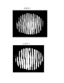
- the difference between the maximum value and the minimum width of the gap between two adjacent slits in the polarizing laminate (slit interval) is 1.05 mm or less. Provide your body.
- Another aspect of the present invention is that in a polarizing laminate formed by any of the above or a combination thereof, the difference between the maximum and minimum widths of the gap between two adjacent slits of the protective layer (slit spacing) is
- This is a polarizing laminate characterized by having a thickness of 0.75 mm or less.
- Another aspect of the present invention is a polarizing laminate made of any of the above or a combination thereof, characterized in that the protective layer on at least one side has a retardation value of 3000 to 5000 nm.
- Another aspect of the present invention is a polarizing laminate made of any of the above or a combination thereof, characterized in that the protective layer on the opposite side has a retardation value of less than 100 nm.
- Another aspect of the present invention is that in a polarizing laminate formed by any of the above or a combination thereof, the difference between the maximum and minimum retardation values of the protective layer on at least one side of the polarizing laminate is less than 300 nm. This is a polarizing laminate with special characteristics.
- Another aspect of the present invention is a polarizing laminate formed by any one of the above or a combination thereof, characterized in that the thickness of the protective layer is thicker than 100 ⁇ m.
- Another aspect of the present invention is a polarizing laminate formed by any one of the above or a combination thereof, characterized in that the thickness of the adhesive layer is less than 40 ⁇ m.
- Another aspect of the present invention is a polarizing laminate made of any of the above or a combination thereof, wherein the protective layer is made of polycarbonate resin or polyamide resin.
- Another aspect of the present invention is a polarized lens for sunglasses using a polarizing laminate formed by any one of the above or a combination thereof, in which two adjacent lenses have optical distortion measured based on MIL-DTL-43511D.
- a polarized lens for sunglasses in which the difference between the maximum and minimum widths of the gaps formed by the slits (slit interval) is 1.05 mm or less.
- FIG. 1 is an image of the optical slit width of the polarizing laminate according to the present invention and the optical slit width of a comparative example.
- a polarizing film is produced by swelling a base resin film in water and then impregnating it with a dye solution containing the dichroic organic dye of the present invention while stretching it in one direction. By dispersing it in an oriented state in a material resin to obtain a film imparted with polarizing properties and a desired color tone.
- Polyvinyl alcohols are used as the base material of the polarizing film used at this time, and these polyvinyl alcohols include polyvinyl alcohol (hereinafter referred to as PVA), PVA with a trace amount of acetate structure remaining, PVA derivatives, or Analogues such as polyvinyl formal, polyvinyl acetal, and saponified ethylene-vinyl acetate copolymers are preferred, and PVA is particularly preferred.
- the molecular weight of the PVA film is preferably a weight average molecular weight of 50,000 to 350,000, more preferably a molecular weight of 100,000 to 300,000, particularly a molecular weight of 150,000.
- the above is preferable.
- the magnification when stretching the PVA film is preferably 2 to 8 times, particularly 3 to 6.5 times, particularly preferably 3.5 to 4.5 times, from the viewpoint of dichroic ratio and film strength after stretching.
- the thickness of the stretched PVA film is not particularly limited, but it is preferably about 20 ⁇ m or more and 50 ⁇ m or less from the viewpoint that it can be handled without being integrated with a protective film or the like.
- the typical manufacturing process when using PVA as the base film is: (1) Wash PVA while swelling it in water to remove impurities, (2) While stretching as appropriate, (3) Dyeing in a dyeing tank, (4) Crosslinking or chelation treatment in a treatment tank with boric acid or a metal compound, (5) drying; Manufactured in the process of Incidentally, steps (2) and (3) (or (4) in some cases) may be performed in the appropriate order or at the same time.
- step (1) of swelling and washing with water the PVA film, which easily breaks in a dry state at room temperature, is uniformly softened and stretched by absorbing water. It is also a step to remove water-soluble plasticizers used in the PVA film manufacturing process, or to preliminarily adsorb additives as appropriate. At this time, the PVA film does not swell sequentially and uniformly, and variations always occur. Even in this state, it is important to take measures to uniformly apply as little force as possible to prevent local stretching or insufficient stretching and to suppress the occurrence of wrinkles. Furthermore, in this step, it is most desirable to simply swell the film uniformly, and avoid excessive stretching as much as possible as this may cause unevenness.
- step (2) the stretching is usually carried out to 2 to 8 times. Since it is important that the polarizing film in the present invention has good subsequent processability, the stretching ratio is selected from 3 to 6.5 times, especially 3.5 to 4.5 times, and the orientation is maintained even in this state. is preferable. In a stretched and oriented state, the longer the time it remains in water and the longer it takes to dry, the more the orientation will be relaxed. Therefore, from the perspective of maintaining higher performance, the stretching process is set to be shorter. However, after stretching, it is preferable to remove moisture as quickly as possible, that is, immediately carry out the drying process and dry while avoiding excessive heat load.
- the stretching ratio in this application is a stretching ratio based on the original fabric of a polyvinyl alcohol resin film.
- the dyeing in step (3) is done by adsorbing or depositing the dye onto the polymer chains of the oriented polyvinyl alcohol resin film.
- This step can be carried out either before, during or after uniaxial stretching, and there is no major change; however, since the interface, a highly regulated surface, is most easily oriented, it is preferable to select conditions that take advantage of this.
- the temperature is usually selected from a high temperature of 40 to 80°C in view of the requirement for high productivity, but in the present invention it is usually selected from 25 to 45°C, preferably 30 to 40°C, particularly 30 to 35°C.
- Step (4) is performed to improve heat resistance, water resistance, and organic solvent resistance.
- Treatment with boric acid improves heat resistance by crosslinking between PVA chains, but it can be done either before, during or after uniaxial stretching of the polyvinyl alcohol resin film, and there is no major change.
- the metal compound mainly forms a chelate compound with the dye molecule to stabilize it, and is usually carried out after dyeing or at the same time as dyeing.
- metal compounds there are transition metals that belong to any of the 4th period, 5th period, and 6th period, and the above-mentioned heat resistance and solvent resistance effects are confirmed in the metal compound.
- metal salts such as acetates, nitrates, and sulfates of fourth period transition metals such as chromium, manganese, cobalt, nickel, copper, and zinc are preferred.
- compounds of nickel, manganese, cobalt, zinc, and copper are more preferred because they are inexpensive and have excellent effects, and nickel is particularly preferred.
- More specific examples include manganese (II) acetate tetrahydrate, manganese (III) acetate dihydrate, manganese (II) nitrate hexahydrate, manganese (II) sulfate pentahydrate, Cobalt (II) acetate tetrahydrate, cobalt (II) nitrate hexahydrate, cobalt (II) sulfate heptahydrate, nickel (II) acetate tetrahydrate, nickel (II) nitrate hexahydrate, Nickel (II) sulfate hexahydrate, zinc (II) acetate, zinc (II) sulfate, chromium (III) nitrate nonahydrate, copper (II) acetate monohydrate, copper (II) nitrate trihydrate copper(II) sulfate pentahydrate, and the like. Any one of these metal compounds may be used alone, or a plurality
- the content of the metal compound and boric acid in the polarizing film is such that the content of the metal compound is 0.2 to 20 mg as metal per 1 g of the polarizing film, from the viewpoint of imparting heat resistance and solvent resistance to the polarizing film.
- 0.2 to 2 mg is more preferable.
- the concentration of the metal compound impregnated into the polarizing film is 200 ppm to 2500 ppm, more preferably 200 ppm to 2000 ppm, even more preferably 400 ppm to 1800 ppm, even more preferably 800 ppm to 2300 ppm, and still more preferably 600 ppm to 1600 ppm. It is.
- concentration of the metal compound is less than 200 ppm, color unevenness tends to occur, and when it exceeds 2500 ppm, a problem occurs in heat and humidity resistance.
- a polarizing film is impregnated with a metal compound in a processing bath, a chelate is formed between the dye molecules and the polarizing film, and it is thought that changes in the orientation of the dye can be suppressed. If a large amount of metal compound is added, the excess metal compound that is not used in the chelate will react with the dye molecules, making it difficult to adjust the color tone, but if no metal compound is added, the dichroic ratio will decrease; Since it is necessary to add a high dichroic ratio dye to compensate, the polarizing film becomes highly oriented in a wet heat environment, resulting in a large wet heat color change. Therefore, a polarizing film is manufactured by adding an appropriate amount of metal compound necessary for chelate formation.
- the content of boric acid is preferably 0.3 to 30 mg, more preferably 0.5 to 10 mg, as boron.
- the composition of the treatment liquid used for the treatment is set to satisfy the above content, and generally the concentration of the metal compound is 0.5 to 30 g/L and the concentration of boric acid is 2 to 20 g/L. preferable.
- the content of metal and boron contained in the polarizing film can be analyzed by atomic absorption spectrometry.
- the temperature is usually the same as that for dyeing, but is usually selected from 20 to 70°C, preferably 25 to 45°C, more preferably 30 to 40°C, particularly 30 to 35°C. Further, the time is usually selected from 0.5 to 15 minutes.
- step (5) the dyed uniaxially stretched PVA film that has been stretched, dyed, and optionally treated with boric acid or a metal compound is dried.
- PVA film exhibits heat resistance corresponding to the amount of water it contains, and when the temperature increases in a state where it contains a large amount of water, disturbances from the uniaxially stretched state occur in a shorter time. A decrease in dichroic ratio occurs.
- Drying of the film proceeds from the surface, and it is preferable to dry from both surfaces, and it is preferable to dry the film while removing water vapor by blowing dry air.
- the water content of the polarizing film at this stage is preferably 5% or less. In the drying process, it is difficult to maintain a moisture content of less than 2%, and it is also undesirable from the viewpoint of the strength of the polarizing film.
- a suitable moisture content is 2.5% to 5.0%.
- the dye is not particularly limited as long as it can be adsorbed and aligned on the PVA polarizing film.
- the transmittance of the PVA polarizing film dyed with the dichroic organic dye composition is the upper limit
- the coloring organic dye composition The transmittance can be selected from a wide range with the lower limit being the transmittance of a PVA polarizing film dyed with the composition.
- the color tone is mainly adjusted by the organic dye composition for coloring, and a wide range of color tones can be obtained corresponding to changes in the usage ratio without substantially considering changes in the degree of polarization.
- thermosetting material are preferred in consideration of stability during heat bending and injection molding processes, and in particular, two-component thermosetting urethane resins consisting of a polyurethane prepolymer, which is a urethane resin material, and a curing agent. Resins are preferred.
- the polyurethane prepolymer is a compound obtained by reacting a diisocyanate compound and a polyoxyalkylene diol at a certain ratio, and is a compound having isocyanate groups at both ends.
- Diisocyanate compounds used in polyurethane prepolymers include diphenylmethane-4,4'-diisocyanate, tolylene diisocyanate, hexamethylene diisocyanate, isophorone diisocyanate, 4,4'-dicyclohexylmethane diisocyanate, lysine isocyanate, and hydrogenated xylylene diisocyanate.
- Isocyanates can be used, but diphenylmethane-4,4'-diisocyanate is preferred.
- polyoxyalkylene diol polypropylene glycol, polyethylene glycol, and polyoxytetramethylene glycol can be used, but it is preferable to use polypropylene glycol having a degree of polymerization of 5 to 30.
- the molecular weight of the polyurethane prepolymer is not particularly limited, but usually has a number average molecular weight of 500 to 5,000, preferably 1,500 to 4,000, more preferably 2,000 to 3,000.
- the curing agent is not particularly limited as long as it is a compound having two or more hydroxyl groups, and examples thereof include polyurethane polyol, polyether polyol, polyester polyol, acrylic polyol, polybutadiene polyol, polycarbonate polyol, etc.
- a polyurethane polyol having a hydroxyl group at the end obtained from a specific isocyanate and a specific polyol is preferred.
- Particularly preferred is a polyurethane polyol derived from a diisocyanate compound and a polyol and having hydroxyl groups at least at both ends.
- diisocyanate compound diphenylmethane-4,4'-diisocyanate, tolylene diisocyanate, hexamethylene diisocyanate, isophorone diisocyanate, 4,4'-dicyclohexylmethane diisocyanate, lysine isocyanate, hydrogenated xylylene diisocyanate
- the polyol a product obtained by reacting trimethylolpropane or the like with ethylene oxide or propylene oxide can be used, and it is preferable to use a polypropylene glycol derivative having a degree of polymerization of 5 to 30.
- the molecular weight of this curing agent is not particularly limited, but usually has a number average molecular weight of 500 to 5,000, preferably 1,500 to 4,000, and more preferably 2,000 to 3,000.
- Solvents such as ethyl acetate and tetrahydrofuran can be used for these polyurethane prepolymers and curing agents to adjust the viscosity. Further, when imparting a light control function to the adhesive layer, the use of a solvent is an effective method for uniformly dispersing the photochromic compound in the urethane resin.
- the transparent plastic sheet that is the protective layer in the polarizing laminate sheet of the present invention usually has a thickness of 0.1 to 1 mm, and may be a single layer or a multilayer sheet formed by coextrusion, for example, an aromatic polycarbonate/polycarbonate sheet. Examples include coextruded acrylate sheets.
- the polarizing laminate sheet of the present invention is usually punched into individual lens shapes with protective films attached to both surfaces, then heat bent, the surface protective film is peeled off, and injection molding is performed. It is suitable for manufacturing injection molded polarized lenses integrated with molten resin.
- the resin of the transparent plastic sheet examples include aromatic polycarbonate, amorphous polyolefin, polyacrylate, polysulfone, acetylcellulose, polystyrene, polyester, polyamide, and transparent resins made of mixtures thereof.
- aromatic polycarbonate resins are preferable due to properties such as mechanical strength and impact resistance
- polyolefins and polycarbonate resins are preferable due to properties such as mechanical strength and impact resistance.
- examples include acrylate and polyamide, and in terms of dyeability after lens molding, polyacrylate and polyamide can be used.
- Aromatic polycarbonate sheets are made of 2,2-bis(4-hydroxyphenyl)alkane or 2,2-(4-hydroxy-3,5-dihalogenophenyl) from the viewpoint of film strength, heat resistance, durability, or bending workability.
- a polymer produced by a well-known method from a bisphenol compound represented by an alkane is preferable, and the polymer skeleton may contain a structural unit derived from a fatty acid diol or a structural unit having an ester bond. , 2-bis(4-hydroxyphenyl)propane are preferred.
- the aromatic polycarbonate preferably has a viscosity average molecular weight of 12,000 to 40,000, more preferably 20,000 to 35,000. Furthermore, aromatic polycarbonate has a large photoelastic constant, and colored interference fringes are likely to occur due to birefringence due to stress and orientation.
- the alicyclic polyester resin of the present invention used as a sheet or film for a protective layer as a composition with an aromatic polycarbonate is, for example, a dicarboxylic acid component represented by 1,4-cyclohexanedicarboxylic acid and 1,4- A diol component represented by cyclohexanedimethanol and a small amount of other components are subjected to an esterification or transesterification reaction, and then a polymerization catalyst is added as appropriate and the pressure inside the reaction tank is gradually reduced to perform polycondensation. It can be obtained by a known reaction method.
- the alicyclic dicarboxylic acid or its ester-forming derivative includes 1,2-cyclohexanedicarboxylic acid, 1,3-cyclohexanedicarboxylic acid, 1,4-cyclohexanedicarboxylic acid, and 1,4-decahydronaphthalenedicarboxylic acid. acid, 1,5-decahydronaphthalene dicarboxylic acid, 2,6-decahydronaphthalene dicarboxylic acid, 2,7-decahydronaphthalene dicarboxylic acid, and ester-forming derivatives thereof.
- the polyamide resin used in the transparent plastic sheet of the present invention is preferably one called amorphous polyamide or microcrystalline polyamide from the viewpoint of transparency and molding processability, and one that can be processed by injection molding as described below is preferable. That is, it can be suitably used as long as it is thermoplastic, exhibits melt fluidity that allows molding at a temperature below the thermal decomposition temperature, and has an appropriate Tg (glass transition temperature).
- amorphousness When amorphousness is a condition, the amount of repeating units that become crystalline is limited, and examples of molecular structures that inhibit crystallinity include structures that impart steric hindrance, and the introduction of branched structures and substituents , bulky molecular structures such as cycloalkanes are used.
- Polyamide generally has structural units derived from monomers such as diamines, dicarboxylic acids, and aminocarboxylic acids.
- Aromatic polyamides and alicyclic polyamides are produced, in principle, by making the structural unit derived from at least one monomer constituting the fully aliphatic polyamide aromatic or alicyclic. All or part of these monomers may be aromatic or alicyclic, such as partially aromatic polyamide, aromatic partially alicyclic polyamide, partially aromatic partially alicyclic polyamide, partially aromatic alicyclic polyamide, partially alicyclic polyamide, etc.
- polyamides or a combination thereof can be used in the present invention
- polyamides having an alicyclic structure are preferably used as a typical example of amorphous polyamides having amorphous properties and appropriate heat resistance. be able to. Note that, in consideration of optical properties such as retardation, which will be described later, it is desirable to include an aromatic moiety.
- Known transparent polyamide resins for lenses include those with a heat distortion temperature in the range of 100 to 170°C, which is an index of heat resistance, and include aromatic polyamide resins, alicyclic polyamide resins, aliphatic polyamide resins, and These copolymers can be mentioned, and alicyclic polyamide resins are preferred from the viewpoint of the balance of mechanical strength, chemical resistance, transparency, etc., but two or more types of polyamide resins may be combined.
- polyamide resins examples include GLILAMID TR FE5577, XE 3805 (manufactured by EMS), NOVAMID X21 (manufactured by Mitsubishi Engineering Plastics), and Toyobo Nylon T-714E (manufactured by Toyobo).
- (Meth)acrylic resin is a homopolymer of various (meth)acrylic acid esters represented by polymethyl methacrylate (PMMA) and methyl methacrylate (MMA), or a combination of PMMA or MMA and one or more other monomers.
- a copolymer of these resins may be used, and a mixture of two or more of these resins may be used.
- preferred are (meth)acrylates containing a cyclic alkyl structure that have low birefringence, low moisture absorption, and excellent heat resistance.
- Examples of the above (meth)acrylic resins include Acrypet (manufactured by Mitsubishi Rayon), Delpet (manufactured by Asahi Kasei Chemicals), and Parapet (manufactured by Kuraray).
- a protective layer having a retardation value that does not inhibit the function of the polarizing film layer provided in the inner layer is disposed at least at a position that will become a convex surface after lens processing.
- a film manufactured by a casting method that is less likely to promote molecular orientation can be suitably used as a protective layer. Care must be taken to ensure that the retardation value does not become larger than the above.
- a protective layer with an extremely large retardation value for example, 1300 nm or more, preferably 2000 nm or more, more preferably 3000 nm or more, more preferably 4000 nm or more, is processed into the lens.
- an extremely large retardation value for example, 1300 nm or more, preferably 2000 nm or more, more preferably 3000 nm or more, more preferably 4000 nm or more.
- the retardation value is an in-plane retardation value.
- the in-plane retardation value can be derived from the refractive index in the slow axis direction, the refractive index in the fast axis direction, and the thickness of the film when the incident linearly polarized light is decomposed into the slow axis and fast axis. It is within the scope of knowledge.
- the retardation value is a value measured at 590 nm.
- a measuring device there is a retardation measuring device: RETS-100 manufactured by Otsuka Electronics.
- examples include a draw stretching method in which the film is stretched while being pulled out, and an offline stretching method in which it is wound once after molding and then stretched separately.
- the melt extrusion molding method for example, the polyamide resin or the resin constituting the protective layer is melt-mixed in an extruder, extruded from a die (such as a T-die), and cooled to produce a transparent plastic used for the protective layer.
- the resin temperature when melting and molding the resin constituting the protective layer (melt molding) varies depending on the resin, but can usually be selected from a temperature range of about 120°C to 350°C, for example, 130 to 350°C.
- the temperature is about 300°C, preferably 150 to 280°C, more preferably about 160 to 250°C.
- the stretching process can be performed by increasing the drawing speed higher than the speed of the cooling roll.
- the specific method of stretching is not particularly limited. In order to suppress stretching unevenness, it is preferable to keep the resin temperature of the rolls in the stretching portion constant while heating the rolls with a mold temperature controller or the like as appropriate. Generally, it is possible to stretch the resin constituting the protective layer near the Tg while maintaining a suitable appearance as a sheet for sunglasses. When stretching is performed at a temperature where the resin temperature is lower than the Tg of the resin used, stretching tends to be uneven, resulting in uneven stretching between stretched and non-stretched areas. Further, when stretching at a temperature higher than Tg, the transparent plastic film is welded to the roll, resulting in problems such as leaving marks when the film is peeled off from the roll.
- Tg as used in the present invention suggests a midpoint temperature among the starting point, midpoint, and end point temperature in a Tg curve measured by DSC.
- the resin temperature of the protective layer during stretching is also related to the provision of retardation. If the stretching process is carried out at a temperature range where the resin temperature of the film during stretching is lower than the Tg of the resin used, it is easier to impart higher retardation, and the higher the temperature, the more difficult it is to develop retardation. becomes. Furthermore, after stretching, it is preferable to cool the film as quickly as possible, so that the retardation and the angle between the slow axis and the fast axis can be fixed. Furthermore, when stretching is performed at a temperature range lower than Tg, it may affect problems such as shrinkage after sheet molding, so it is essential to select the stretching temperature conditions in consideration of this point.
- a resin molded by melt extrusion When a resin molded by melt extrusion is stretched to form a protective layer, it is preferable to use a resin with a high intrinsic birefringence value. This makes it easier to develop high retardation with lower stress and to maintain retardation even when stretched at a resin temperature higher than Tg. Since the intrinsic birefringence value varies depending on the composition or type of resin and also depends on the desired retardation value, it is essential to appropriately adjust the stretching ratio in the stretching process. In addition, generally, at least 1.1 times, preferably 1.2 times, more preferably 1.3 times or more is required. The upper limit is determined from the viewpoint of production efficiency because as the magnification increases, neck-in is accelerated or the risk of breakage occurs. Usually it is about 2.2 times, preferably about 2.0 times or less.
- retardation In order to prevent colored interference fringes due to stretching of the transparent plastic sheet that is the protective layer, it is preferable to have retardation (Re, hereinafter simply referred to as retardation means in-plane retardation) of 1500 to 10000 nm.
- the preferable lower limit of retardation is 2000 nm
- the next preferable lower limit is 2500 nm
- the more preferable lower limit is 3000 nm
- the still more preferable lower limit is 3500 nm
- the even more preferable lower limit is 4000 nm.
- rainbow spots may appear.
- a preferable upper limit is 8000 nm, a more preferable upper limit is 7000 nm, an even more preferable upper limit is 6000 nm, an especially preferable upper limit is 5500 nm, and a most preferable upper limit is 5000 nm.
- a transparent plastic sheet having a retardation higher than this would have a large thickness and would be unsuitable for use in the present invention.
- the transparent plastic sheet in this polarizing sheet preferably has a small deviation in in-plane retardation.
- the in-plane retardation deviation is based on the measured value when a molded or stretched transparent plastic sheet is divided into three parts in parallel in the length direction and the retardation in the center and both end areas is measured. It can be found as
- the polarizing laminate of the present invention is prepared by using the polarizing film described above as a functional layer, applying the adhesive layer using a gravure coater or die coater, pasting the protective layer on both sides, and cutting the film to a desired length. can do.
- a sufficient discharge rate is maintained in order to avoid entrainment of air bubbles due to insufficient coating liquid during adhesive coating.
- the polarizing laminate is punched into a shape for each lens, and then bent.
- processing into individual lens-shaped products is usually performed by punching out a plurality of lens-shaped products using a punching blade made of a Thomson blade.
- the shape of the individual lens-shaped product is appropriately selected depending on the shape of the final product (sunglasses, goggles, etc.).
- a standard lens shape product for binocular use is a disc with a diameter of 80 mm or a slit shape with both ends thereof cut to the same width in a direction perpendicular to the polarization axis.
- bending may cause deterioration of the layer that exhibits the functionality of the present polarizing sheet, including the colored polarizing film of the present invention. Determined based on the condition that it will not substantially occur.
- the bending process is performed so as to follow the surface of a mold used for injection molding.
- the polarizing film is prone to cracks along the stretching direction during bending, so-called film breaks, so it is necessary to select conditions that suppress the occurrence of these cracks.
- the temperature of the mold during bending of the polarizing sheet is preferably below the glass transition temperature of the resin used, and in addition, the preheating treatment ensures that the temperature of the polarizing sheet immediately before bending is at least 50°C lower than the glass transition temperature of the resin used.
- the temperature is preferably lower than the glass transition point, particularly preferably 40° C. lower than the glass transition point and lower than 5° C. lower than the glass transition point.
- the processing conditions for injection molding must be such that lenses with excellent appearance can be manufactured. From this point of view, injection conditions such as injection pressure, holding pressure, metering, molding cycle, etc., are selected to obtain a lens molded product with a high filling rate and without burrs.
- the temperature is selected appropriately from 260 to 320°C.
- the mold temperature is selected from a temperature that is 100°C lower than the glass transition temperature of the aromatic polycarbonate resin and lower than the glass transition point, preferably a temperature that is 80°C lower than the glass transition temperature and lower than 15°C lower than the glass transition point. In particular, the temperature is preferably at least 70°C lower than the glass transition temperature and lower than 25°C lower than the glass transition temperature.
- One embodiment of the present invention also includes bending polarized lenses and exit polarizing lenses described above.
- the polarized lens of the present invention has an optical distortion that satisfactorily clears the MIL standard even after undergoing such a manufacturing process, and in particular, it has optical distortion that satisfies the MIL standard as measured by the method described in this specification.
- the difference between the maximum and minimum widths of the gap between two adjacent slits (slit interval) can be 1.05 mm or less.
- the firing temperature is preferably at least 50°C lower than the glass transition temperature of the resin used for the polarizing sheet, and particularly at least 40°C lower than the glass transition point and lower than 15°C lower than the glass transition point.
- the temperature is around 120° C., and the time required to bake the hard coat is approximately 30 minutes to 2 hours.
- Example 1 a) Preparation of polarizing film Polyvinyl alcohol (manufactured by Kuraray Co., Ltd., trade name: VF-PS#7500) was stretched to twice its original size while being swollen in water at 35° C. for 270 seconds. Subsequently, 0.41 g/L dichroic dye Eisen Premium Blue 6GLH (C.I. Blue 202), 0.09 g/L Sumilite Red 4B (C.I. Red 81), 0.03 g/L of chrysofenine (C.I. Yellow 12) and 10 g/L of anhydrous sodium sulfate at 35°C.
- dichroic dye Eisen Premium Blue 6GLH C.I. Blue 202
- 0.09 g/L Sumilite Red 4B C.I. Red 81
- 0.03 g/L of chrysofenine C.I. Yellow 12
- This dyed film was stretched 4 times while immersed in an aqueous solution containing 2.3 g/L of nickel acetate and 4.4 g/L of boric acid at 35° C. for 120 seconds. After drying the film at room temperature for 3 minutes while maintaining tension, it was heat-treated at 110° C. for 3 minutes to obtain a polarizing film.
- b) Preparation of protective layer and retardation measurement b-1) Polycarbonate protective layer Melt aromatic polycarbonate resin by heating, extruding the molten resin from a T-die with a short-axis extruder, cooling it with a cooling roll, and then winding it with a winder. A polycarbonate film having a thickness of 275 ⁇ m was obtained using an extrusion method. Next, the polycarbonate sheet obtained above was cut into 40 cm squares, fixed on all sides with clamps, held at Tg (midpoint in DSC measurement) temperature for 20 minutes, and then stretched at a stretching ratio of 1.5 times and 2 m/min.
- the film was stretched only in one axis direction at a high speed, and after the stretching, the film was cooled at room temperature for 30 minutes while maintaining the tension state to obtain a polycarbonate protective film with a thickness of 200 ⁇ m. After the post-stretching, approximately 25 mm of the film was cut from both left and right ends in the width direction, retardation was measured, and the film was used to produce a polarizing laminate sheet.
- b-2) Retardation measurement and deviation determination Retardation measurement was performed using WPA-200-L manufactured by Photonics Lattice Co., Ltd.
- a polycarbonate protective film with a length of 300 mm and a width of 295 mm was divided into three parts in the width direction (L, C, R), the average retardation value was calculated by measuring an area of 70 mm on each side, and the standard deviation was determined from the three measurement points.
- polarizing laminate Preparation of polarizing laminate Apply a thermosetting polyurethane adhesive to the polarizing film obtained above, laminate the 200 ⁇ m thick polycarbonate protective film obtained above, and apply the same method to the remaining one side of the polarizing film. A polycarbonate protective film with a thickness of 200 ⁇ m was laminated. After lamination, the adhesive was cured by being left in a constant temperature bath at 70° C. to obtain a polarizing laminate with an adhesive layer of 10 ⁇ m.
- Heat bending involves preheating the punched piece in a preheater, placing it on a partially spherical female mold with a predetermined temperature and a predetermined curvature, and pressing it with a silicone rubber male mold, at the same time starting to reduce the pressure and turning it into a female mold.
- a continuous heat bending device was used, which consisted of the following steps: adsorption, pulling up the male mold, holding the punched piece adsorbed on the female mold in a hot air atmosphere at a predetermined temperature for a predetermined time, and then taking it out.
- the preheating of the punched piece is at an ambient temperature of 136°C when aromatic polycarbonate is used as the protective layer
- the female mold is a partially spherical surface equivalent to 8R (radius of about 65.6mm) with a surface temperature of 139°C, and silicone rubber is heated at a surface temperature of 139°C.
- the pressing time with the male mold was 4 seconds, and the adsorption onto the female mold was 5 minutes in an atmosphere with hot air blowing at a temperature of 170°C.
- molten aromatic polycarbonate (contains ultraviolet absorber, product name: Mitsubishi Engineering Plastics Co., Ltd., IUPILON, CLS-3400). ) was used for injection molding.
- the injection molding conditions were a resin temperature of 290°C, an injection filling speed of 30mm/s, a holding pressure of 30MPa, a mold temperature of 90°C, a cooling time of 30 seconds, and an injection cycle of 70 seconds. Obtained an injection lens.
- Optical distortion measurement d-1) Visual optical distortion measurement method DATA OPTICS INC. .. Optical distortion was measured using a Model E Destination Tester manufactured by Co., Ltd. according to the measurement method described in the specification, and whether the sample was passed or failed was determined visually based on the optical distortion tolerance criteria described in the specification.
- d-2) Optical distortion measurement method using image discrimination device DATA OPTICS INC. The sample was set using a model E destination tester according to MIL-DTL-43511D, Section 4.4.5 and Figure 4, and the observed optical distortion was measured using a digital still camera (Panasonic LUMIX, DMC-TZ10). Photographed (exposure: 1/5, ISO sensitivity: 100, F value: 6.3).
- the photographed image is read in the image discrimination software IV3-CP50 manufactured by Keyence Corporation, and the width of the adjacent slit lines (slit interval) in the image is measured at three points at the top, middle, and bottom for each interval. was performed for 12 intervals.
- the difference between the maximum width and the minimum width for each measured interval was quantified as optical distortion, and in the case of a polarizing laminate, a slit interval of less than 1.05 mm was considered acceptable.
- the slit interval of the polycarbonate protective film was determined to be acceptable if it was 0.75 mm or less.
- Example 2 The same procedure as in Example 1 was carried out except that for the protective layer on one side, the stretching step was omitted and a polycarbonate protective film with a thickness of 200 ⁇ m was used.
- Example 3 The same as Example 1 except that the protective layer on both sides was changed to a polycarbonate protective film with a thickness of 320 ⁇ m, which was formed at a stretching ratio of 1.7 times using an apparatus that can continuously perform processes from melt extrusion of polycarbonate resin to stretching. I did the same.
- Example 4 The protective layer on one side is a polycarbonate protective film with a thickness of 320 ⁇ m, which is formed at a stretching ratio of 1.7 times using a device that can continuously perform processes from melt extrusion of polycarbonate resin to stretching. The same procedure as in Example 1 was carried out except that the steps were omitted and a polycarbonate protective film having a thickness of 280 ⁇ m was used.
- Example 5 The same procedure as in Example 1 was performed except that the protective layer on one side was a 200 ⁇ m thick polycarbonate protective film without the stretching step, and the thickness of the cured adhesive layer was changed to 5 ⁇ m.
- Example 6 The protective layer on one side is a polycarbonate protective film with a thickness of 700 ⁇ m, which was formed at a stretching ratio of 1.3 times using a device that can continuously perform processes from melt extrusion to stretching of polycarbonate resin, and the other protective layer is stretched. The same procedure as in Example 1 was carried out except that the steps were omitted and a polycarbonate protective film having a thickness of 700 ⁇ m was used.
- the protective layer on one side is a polyamide protective layer with a thickness of 275 ⁇ m produced by a melt extrusion method in which amorphous transparent polyamide resin consisting of aliphatic and alicyclic resin is cooled with a cooling roll and then rolled up with a winder. It was made into a film.
- the other protective layer was made by cutting the polyamide protective film obtained above into 40 cm square pieces, fixing them with clamps on all sides, holding them at Tg (midpoint in DSC measurement) temperature for 20 minutes, and then Same as Example 1 except that it was stretched only in the uniaxial direction at a stretching ratio and a stretching speed of 2 m/min, and after stretching, it was cooled at room temperature for 30 minutes while maintaining the tension state to obtain a polyamide protective film with a thickness of 200 ⁇ m.
- a polarizing laminate was created in the same manner.
- the punching process was the same as in Example 1, and the heat bending process also used the same continuous heat bending machine as in Example 1.
- the ambient temperature is 136°C
- the female mold is a partially spherical surface equivalent to 8R (radius about 65.6 mm)
- the surface temperature is 135°C
- the male mold is made of silicone rubber.
- the pressing time was 4 seconds, and the adsorption to the female mold was 5 minutes in an atmosphere where the hot air temperature was 166°C.
- the protective film of the heat-bending punched piece produced above was peeled off, the piece was attached to the mold cavity of an injection molding machine, and injection molded using molten polyamide resin (trade name: EMS-CHEMIE, Grilamid, TR90).
- the injection molding conditions were a resin temperature of 280°C, an injection filling speed of 30mm/s, a holding pressure of 30MPa, a mold temperature of 80°C, a cooling time of 30 seconds, and an injection cycle of 70 seconds. Obtained an injection lens.
- Example 1 The same procedure as in Example 1 was used for the protective layers on both sides, except that a polycarbonate protective film with a thickness of 320 ⁇ m was used, which was formed at a stretching ratio of 2 times using an apparatus that can continuously perform processes from melt extrusion of polycarbonate resin to stretching. went.
- the protective layer on one side is a polycarbonate protective film with a thickness of 400 ⁇ m, which is formed at a stretching ratio of 1.8 times using a device that can continuously perform processes from melt extrusion of polycarbonate resin to stretching.
- the same procedure as in Example 1 was carried out except that the steps were omitted and a polycarbonate protective film having a thickness of 300 ⁇ m was used.
- Example 3 The same as Example 1 except that for the protective layers on both sides, a polycarbonate protective film with a thickness of 700 ⁇ m was used, which was formed at a stretching ratio of 1.5 times using an apparatus that can continuously perform processes from melt extrusion of polycarbonate resin to stretching. I did the same.
- Example 4 The same procedure as in Example 1 was carried out except that the thickness of the cured adhesive layer was changed to 40 ⁇ m.
- the protective layer on one side is a polycarbonate protective film with a thickness of 320 ⁇ m, which is formed at a stretching ratio of 1.7 times using a device that can continuously perform processes from melt extrusion of polycarbonate resin to stretching.
- the same procedure as in Example 1 was carried out except that the steps were omitted and a polycarbonate protective film having a thickness of 100 ⁇ m was used.
- Example 6 The same procedure as in Example 1 was carried out, except that the protective layers on both sides were replaced with a polycarbonate protective film having a thickness of 200 ⁇ m, and the stretching process was omitted.
- Example 7 The same procedure as in Example 7 was carried out except that the stretching speed was 4 m/min and the protective layers on both sides were changed to polyamide protective films with a thickness of 320 ⁇ m.
- the optical distortion of the protective layer laminated via an adhesive layer on both sides of a polarizing film made of a uniaxially stretched polyvinyl alcohol resin film remains unchanged even after it is made into a polarizing laminate. It has become clear that there is an impact. Specifically, when the slit interval in the protective layer is larger than 0.75 mm, the slit interval in the polarizing laminate is larger than 1.05 mm, and visual optical distortion is equivalent to failure. It has become clear that the optical distortion of this protective layer tends to worsen when the variation in retardation is large.
- the optical distortion in the polarizing laminate is also caused by the fact that the thickness of the adhesive layer is increased to 40 ⁇ m or more in Comparative Example 4, and the thickness of the protective layer is decreased to 100 ⁇ m or less in Comparative Example 6. It was also found that it got worse.
- the present invention provides a polarizing laminate with uniform slit width. This makes it possible to easily provide a polarizing sheet with extremely low optical distortion equivalent to so-called military grade.
Landscapes
- Physics & Mathematics (AREA)
- General Physics & Mathematics (AREA)
- Optics & Photonics (AREA)
- Health & Medical Sciences (AREA)
- Ophthalmology & Optometry (AREA)
- General Health & Medical Sciences (AREA)
- Polarising Elements (AREA)
- Eyeglasses (AREA)
Abstract
Description
(偏光フィルム)
偏光フィルムは、基材となる樹脂フィルムを水中で膨潤させた後に、本願発明の二色性有機染料を含有する染色液に、一方向に延伸させつつ含浸することにより、二色性色素を基材樹脂中に配向した状態で分散させて、偏光性および所望の色調を付与したフィルムを得ることによる。
(1)PVAを水中にて膨潤させつつ水洗し、不純物を取り除き、
(2)適宜、延伸しつつ、
(3)染色槽にて染色し、
(4)ホウ酸または金属化合物による処理槽にて架橋ないしキレート化処理し、
(5)乾燥する、
との工程にて製造される。尚、工程(2)、(3)(場合により(4))は、適宜、その順序をかえても、また、同時に行っても良いものである。
また、色調は、主に着色用有機染料組成物にて調整され、偏光度の変化を実質的に考慮することなく使用量比の変更に対応した広い範囲の色調を得ることができる。
偏光フィルムと透明保護シートとを積層して偏光積層シートとするために偏光フィルムと透明保護シートとの間に接着層を介在させる。通常、偏光積層シートに用いられる接着層の材料としては、ポリビニルアルコール樹脂系材料、アクリル樹脂系材料、ウレタン樹脂系材料、ポリエステル樹脂系材料、メラミン樹脂系材料、エポキシ樹脂系材料、シリコーン系材料等がある。
本願においては、熱曲げ加工、射出成型工程での安定性を考慮した場合、熱硬化性材料が好ましく、特にウレタン樹脂系材料であるポリウレタンプレポリマーと硬化剤からなる2液型の熱硬化性ウレタン樹脂が好ましい。
次に、本発明の偏光積層シートにおける保護層である透明プラスチックシートは、通常、厚み0.1~1mmであり、単層あるいは共押し出し法による多層のシートでもよく、例えば、芳香族ポリカーボネート/ポリアクリレートの共押し出しシートなど、が挙げられる。また、本発明の偏光積層シートは、通常、両表面に保護フィルムを付した状態で、個別のレンズ形状に打ち抜き、次に、熱曲げ加工され、表面保護フィルムを剥離して、射出成形金型に装着されて、溶融樹脂と一体化した射出成形偏光レンズの製造に好適である。
このような低いリタデーションとする場合、より分子配向を促しにくいキャスト法などにより製造されたフィルムを保護層として好適に用いることができるが、キャスト製法においても、引き取り時に不要な応力が発生して必要以上にリタデーション値が大きくなることの無いように注意が必要である。
上記した偏光フィルムを機能層とし、上記接着層をグラビアコーター、或いはダイコーターなどで塗布して、上記保護層を両面に貼り合わせ、所望の長さに裁断することにより本発明の偏光積層体とすることができる。ラミネート方法においては特に限定はないが、接着材塗工時に塗工液不足による気泡巻き込みなどを回避するために、十分な吐出量を維持する。また、貼り合わせ時の張力、及び貼り合わせロールのニップ圧などは、貼り合わせ後のシートの反り状態などを考慮して、適切に調節することが望ましい。
次いで、偏光積層体を個々のレンズ用の形状に打ち抜きなどにて加工した後、曲げ加工を施す。個々のレンズ形状品への加工は、生産性などから、通常、トムソン刃からなる打ち抜き刃を用いた、複数のレンズ形状品の打ち抜き加工による。個別レンズ形状品の形状は、最終製品の形状(サングラス、ゴーグルなど)により適宜、選択される。二眼用の場合の標準的なレンズ形状品は、直径80mmの円盤あるいはその両端を偏光軸に垂直な方向に同幅切り取ったスリット形状である。また、曲げ加工は、上記の本偏光シートに用いる保護層用の透明プラスチックシートの種類の選択でも触れたが、本発明の着色偏光フィルムを含む本偏光シートの機能性を発揮する層の劣化が実質的に発生しないとの条件により決定される。
a)偏光フィルムの作製
ポリビニルアルコール(クラレ株式会社製、商品名:VF-PS#7500)を35℃の水中で270秒間膨潤しつつ、2倍に延伸した。
引き続いて、0.41g/Lの二色性色素アイゼンプレミアムブルー6GLH(C.I.Blue 202)、0.09g/Lのスミライトレッド4B(C.I.Red 81)、0.03g/Lのクリソフェニン(C.I.Yellow 12)及び10g/Lの無水硫酸ナトリウムを含む35℃の水溶液中で染色した。
この染色フィルムを酢酸ニッケル2.3g/Lおよびホウ酸4.4g/Lを含む水溶液中35℃で120秒間浸漬しつつ、4倍に延伸した。そのフィルムを緊張状態が保持された状態で室温にて3分乾燥を行った後、110℃で3分間加熱処理し、偏光フィルムを得た。
b-1)ポリカーボネート保護層
芳香族ポリカーボネート樹脂を加熱溶融し、短軸押し出し機でTダイから溶融樹脂を押し出し、冷却ロールで冷却後に巻取り機で巻き取る溶融押し出し製法にて製膜された厚み275μmのポリカーボネートフィルムを得た。次いで、上記で得たポリカーボネートシートを40cm角に切り出し、四方をクランプで固定してTg(DSC測定における中間点)温度で20分保持した後、1.5倍の延伸倍率、2m/minの延伸速度で一軸方向のみに延伸して、延伸後緊張状態を保持したまま室温で30分間冷却し、厚さ200μmのポリカーボネート保護フィルムを得た。後延後フィルムの幅方向に対して、左右両端からおよそ25mmを切断し、リタデーション測定を行うとともに偏光積層シートの製造に用いた。
b-2)リタデーション測定および偏差の決定
リタデーション測定はフォトニクスラティス社製のWPA-200-Lを用いて、長さ300mm、幅295mmのポリカーボネート保護フィルムにて、幅方向で3分割(L、C、R)し、一辺70mmの範囲をしてエリア測定した平均レタデーション値を算出し、測定箇所3箇所から標準偏差を決定した。
上記で取得した偏光フィルムに熱硬化性ポリウレタン系接着剤を塗布して、上記で取得した厚み200μmのポリカーボネート保護フィルムを積層し、偏光フィルムの残りの片面へ同じように厚み200μmのポリカーボネート保護フィルムを積層した。積層後、70℃の恒温槽に放置して接着剤を硬化させ、接着層10μmの偏光積層体を得た。
直径80mmの円盤をその中心を通る直線の両側を平行に同量切り取り、幅55mmとしたスリット形状或いはカプセルや俵の縦断面形状であり、切り取られない両側の円弧部分に位置決め用の小突起を持つ二眼レンズ用の打ち抜き片を作成した。打ち抜き方向は、打ち抜き片の長手方向を偏光フィルムの吸収軸方向とした。製造した打ち抜き片を熱曲げ加工した。
熱曲げは、打ち抜き片を予熱器にて予備加熱し、これを所定の温度、所定の曲率の部分球面雌型に乗せ、シリコンゴム製雄型にて押し付けると同時に減圧を開始して雌型に吸着させ、雄型を引き上げ、雌型に吸着された打ち抜き片を所定の時間、所定の温度の熱風雰囲気中で保持した後、取り出す工程からなる連続熱曲げ装置を使用した。
上記において、打ち抜き片の予備加熱は芳香族ポリカーボネートを保護層として用いた場合には136℃雰囲気温度とし、雌型は8R相当(半径約65.6mm)の部分球面で表面温度139℃、シリコンゴム製雄型による押し付け時間は4秒、雌型への吸着は、吹き込み熱風温度が170℃である雰囲気下で5分間とした。
上記で製造した熱曲げ打ち抜き片の保護フィルムを剥離し、射出成形機の金型キャビチーに装着し、溶融芳香族ポリカーボネート(紫外線吸収剤配合、商品名;三菱エンジニアリングプラスチックス社、IUPILON、CLS-3400)を用いて、射出成形した。射出成形条件は、樹脂温度290℃、射出充填速度30mm/s、保持圧30MPa、金型温度90℃、冷却時間30秒とし、射出サイクル70秒にそれぞれ設定して射出し、厚み2.2mmの射出レンズを得た。
d-1)目視による光学歪み測定方法
米国国防省の定めるミリタリー規格であるMIL-DTL-43511Dに記載の3.5.5項、4.3.5項に従い、DATA OPTICS INC.社製のモデルEディストネーションテスターを用いて規格書に記載の測定方法に準じて光学歪みを測定し、規格書に記載の光学歪み許容基準において合格、不合格を目視にて判断した。
d-2)画像判別装置による光学歪み測定方法
DATA OPTICS INC.のモデルEディストネーションテスターを用いてMIL-DTL-43511D、4.4.5項およびFigure4の記載に従ってサンプルをセットし、観察される光学歪みをデジタルスチールカメラ(Panasonic LUMIX、DMC-TZ10)にて撮影した(露光:1/5、ISO感度:100、F値:6.3)。撮影した画像をキーエンス社製画像判別ソフトIV3-CP50で読み込み、画像中のスリット線における隣り合うスリット線の幅(スリット間隔)を、1間隔につき上、中、下の3箇所測定し、その測定を12間隔行った。測定した1間隔ごとでの最大幅と最小幅の差を光学歪みとして定量化し、偏光積層体の場合はスリット間隔が1.05mm未満を合格とした。また、ポリカーボネート保護フィルムのスリット間隔は0.75mm以下を合格として合否判定を行った。
偏光積層体を熱曲げ加工した曲面偏光板を、互いの偏光軸が直交位となるように配置した平面偏光板と重ねた状態で平面偏光板側から蛍光灯の光を当てた際に、光が透過しないかを目視にて観察した。
片面の保護層にて、延伸工程を除いた、厚み200μmのポリカーボネート保護フィルムに変えた以外は実施例1と同様に行った。
両面の保護層にて、ポリカーボネート樹脂の溶融押し出しから延伸までを連続して行える装置にて、延伸倍率1.7倍で製膜した、厚み320μmのポリカーボネート保護フィルムに変えた以外は実施例1と同様に行った。
片面の保護層にて、ポリカーボネート樹脂の溶融押し出しから延伸までを連続して行える装置にて、延伸倍率1.7倍で製膜した、厚み320μmのポリカーボネート保護フィルムとし、もう一方の保護層は延伸工程を除いた、厚み280μmのポリカーボネート保護フィルムに変えた以外は実施例1と同様に行った。
片面の保護層を、延伸工程を除いた、厚み200μmポリカーボネート保護フィルムとし、硬化した接着層の厚みを5μmに変えた以外は実施例1と同様に行った。
片面の保護層にて、ポリカーボネート樹脂の溶融押し出しから延伸までを連続して行える装置にて、延伸倍率1.3倍で製膜した、厚み700μmのポリカーボネート保護フィルムとし、もう一方の保護層は延伸工程を除いた、厚み700μmのポリカーボネート保護フィルムに変えた以外は実施例1と同様に行った。
片面の保護層は、脂肪族、及び脂環族からなる非晶質透明ポリアミド樹脂の溶融押出し、冷却ロールで冷却後に巻き取り機で巻き取る溶融押し出し製法にて作製した、厚みを275μmのポリアミド保護フィルムとした。また、もう一方の保護層は、上記で得たポリアミド保護フィルムを40cm角に切り出し、四方をクランプで固定してTg(DSC測定における中間点)温度で20分保持した後、1.5倍の延伸倍率、2m/minの延伸速度で一軸方向のみに延伸して、延伸後緊張状態を保持したまま室温で30分間冷却して、厚みを200μmとしたポリアミド保護フィルムとした以外は実施例1と同様に偏光積層体を作成した。
打ち抜き加工は実施例1と同様とし、熱曲げ加工も実施例1と同様に連続熱曲げ装置を使用した。なお、ポリアミド樹脂からなる透明保護シートを保護層とした場合には、136℃雰囲気温度とし、雌型は8R相当(半径約65.6mm)の部分球面で表面温度135℃、シリコンゴム製雄型による押し付け時間は4秒、雌型への吸着は、吹き込み熱風温度が166℃である雰囲気下で5分間とした。
上記で製造した熱曲げ打ち抜き片の保護フィルムを剥離し、射出成形機の金型キャビチーに装着し、溶融ポリアミド樹脂(商品名;EMS-CHEMIE社、Grilamid、TR90)を用いて、射出成形した。射出成形条件は、樹脂温度280℃、射出充填速度30mm/s、保持圧30MPa、金型温度80℃、冷却時間30秒とし、射出サイクル70秒にそれぞれ設定して射出し、厚み2.2mmの射出レンズを得た。
両面の保護層にて、ポリカーボネート樹脂の溶融押し出しから延伸までを連続して行える装置にて、延伸倍率2倍で製膜した、厚み320μmのポリカーボネート保護フィルムに変えた以外は実施例1と同様に行った。
片面の保護層にて、ポリカーボネート樹脂の溶融押し出しから延伸までを連続して行える装置にて、延伸倍率1.8倍で製膜した、厚み400μmのポリカーボネート保護フィルムとし、もう一方の保護層は延伸工程を除いた、厚み300μmのポリカーボネート保護フィルムに変えた以外は実施例1と同様に行った。
両面の保護層にて、ポリカーボネート樹脂の溶融押し出しから延伸までを連続して行える装置にて、延伸倍率1.5倍で製膜した、厚み700μmのポリカーボネート保護フィルムに変えた以外は実施例1と同様に行った。
硬化した接着層の厚みを40μmに変えた以外は実施例1と同様に行った。
片面の保護層にて、ポリカーボネート樹脂の溶融押し出しから延伸までを連続して行える装置にて、延伸倍率1.7倍で製膜した、厚み320μmのポリカーボネート保護フィルムとし、もう一方の保護層は延伸工程を除いた、厚み100μmのポリカーボネート保護フィルムに変えた以外は実施例1と同様に行った。
両面の保護層にて、延伸工程を除いた、厚み200μmのポリカーボネート保護フィルムに変えた以外は実施例1と同様に行った。
延伸速度を4m/minとして、両面の保護層を厚み320μmのポリアミド保護フィルムに変えた以外は実施例7と同様に行った。

Claims (9)
- 一軸延伸されたポリビニルアルコール系樹脂フィルムからなる偏光フィルムの両面に接着層を介して透明プラスチックシートを保護層として配置してなる偏光積層体であって、
MIL-DTL-43511Dに基づき測定される光学歪みにおいて、前記偏光積層体における隣り合う2本のスリットからなる間隙の幅の最大値と最小値の差(スリット間隔)が1.05mm以下である、偏光積層体。 - 前記偏光積層体における前記保護層の隣り合う2本のスリットからなる間隙の幅の最大値と最小値の差(スリット間隔)が0.75mm以下である、請求項1に記載の偏光積層体。
- 少なくとも片面の保護層のリタデーション値が3000~5000nmである、請求項1または2のいずれかに記載の偏光積層体。
- 反対側の保護層のリタデーション値が100nm未満である、請求項3に記載の偏光積層体。
- 前記偏光積層体における前記少なくとも片面の保護層のリタデーション値の最大値と最小値の差が300nm未満である、請求項3に記載の偏光積層体。
- 前記保護層の厚みが100μmより厚い、請求項1に記載の偏光積層体。
- 前記接着層の厚みが40μm未満である、請求項1に記載の偏光積層体。
- 前記保護層がポリカーボネート樹脂もしくはポリアミド樹脂からなる、請求項1に記載の偏光積層体。
- 請求項1に記載の偏光積層体を用いたサングラス用偏光レンズであって、MIL-DTL-43511Dに基づき測定される光学歪みにおいて、隣り合う2本のスリットからなる間隙の幅の最大値と最小値の差(スリット間隔)が1.05mm以下であるサングラス用偏光レンズ。
Priority Applications (1)
| Application Number | Priority Date | Filing Date | Title |
|---|---|---|---|
| US18/996,249 US20250355140A1 (en) | 2022-07-20 | 2023-07-13 | Polarizing sheet |
Applications Claiming Priority (2)
| Application Number | Priority Date | Filing Date | Title |
|---|---|---|---|
| JP2022115936A JP2024013669A (ja) | 2022-07-20 | 2022-07-20 | 偏光シート |
| JP2022-115936 | 2022-07-20 |
Publications (1)
| Publication Number | Publication Date |
|---|---|
| WO2024018992A1 true WO2024018992A1 (ja) | 2024-01-25 |
Family
ID=89617655
Family Applications (1)
| Application Number | Title | Priority Date | Filing Date |
|---|---|---|---|
| PCT/JP2023/025922 Ceased WO2024018992A1 (ja) | 2022-07-20 | 2023-07-13 | 偏光シート |
Country Status (4)
| Country | Link |
|---|---|
| US (1) | US20250355140A1 (ja) |
| JP (1) | JP2024013669A (ja) |
| TW (1) | TW202419905A (ja) |
| WO (1) | WO2024018992A1 (ja) |
Citations (4)
| Publication number | Priority date | Publication date | Assignee | Title |
|---|---|---|---|---|
| US20150007669A1 (en) * | 2013-07-03 | 2015-01-08 | Samsung Display Co., Ltd. | Display device and a method of measuring a strain of the display device |
| WO2016067937A1 (ja) * | 2014-10-31 | 2016-05-06 | 株式会社ウインテック | 熱曲げ偏光シートの包装体および射出偏光レンズ |
| WO2019013078A1 (ja) * | 2017-07-10 | 2019-01-17 | 三菱瓦斯化学株式会社 | 機能性シート |
| JP2022078090A (ja) * | 2017-09-07 | 2022-05-24 | ポリプラ・エボニック株式会社 | 偏光性シート、及びこれを備えた偏光レンズ |
-
2022
- 2022-07-20 JP JP2022115936A patent/JP2024013669A/ja active Pending
-
2023
- 2023-05-19 TW TW112118745A patent/TW202419905A/zh unknown
- 2023-07-13 US US18/996,249 patent/US20250355140A1/en active Pending
- 2023-07-13 WO PCT/JP2023/025922 patent/WO2024018992A1/ja not_active Ceased
Patent Citations (4)
| Publication number | Priority date | Publication date | Assignee | Title |
|---|---|---|---|---|
| US20150007669A1 (en) * | 2013-07-03 | 2015-01-08 | Samsung Display Co., Ltd. | Display device and a method of measuring a strain of the display device |
| WO2016067937A1 (ja) * | 2014-10-31 | 2016-05-06 | 株式会社ウインテック | 熱曲げ偏光シートの包装体および射出偏光レンズ |
| WO2019013078A1 (ja) * | 2017-07-10 | 2019-01-17 | 三菱瓦斯化学株式会社 | 機能性シート |
| JP2022078090A (ja) * | 2017-09-07 | 2022-05-24 | ポリプラ・エボニック株式会社 | 偏光性シート、及びこれを備えた偏光レンズ |
Also Published As
| Publication number | Publication date |
|---|---|
| JP2024013669A (ja) | 2024-02-01 |
| TW202419905A (zh) | 2024-05-16 |
| US20250355140A1 (en) | 2025-11-20 |
Similar Documents
| Publication | Publication Date | Title |
|---|---|---|
| CN110753863B (zh) | 功能性片材 | |
| TWI532595B (zh) | 機能性薄片及使用該機能性薄片之透鏡 | |
| JP2012014001A (ja) | 偏光子の製造方法、偏光子、偏光板、光学フィルムおよび画像表示装置 | |
| JP7555880B2 (ja) | 偏光子、偏光子の製造方法および該偏光子を含む光学積層体 | |
| JP2023025240A (ja) | 偏光フィルムロールの製造方法 | |
| CN104395075A (zh) | 拉伸层压体、制造薄偏光片的方法、由该方法制造的薄偏光片、及包含该薄偏光片的偏光板 | |
| TW201915063A (zh) | 偏光膜、偏光板、偏光板捲材及偏光膜之製造方法 | |
| KR20200054185A (ko) | 편광판, 편광판 롤 및 편광막의 제조 방법 | |
| TWI801395B (zh) | 偏光膜、偏光板、偏光板捲材及偏光膜之製造方法 | |
| CN113543958A (zh) | 用于生产梯度偏振膜的方法和系统 | |
| JP2025107392A (ja) | 偏光膜および偏光板 | |
| WO2024018992A1 (ja) | 偏光シート | |
| WO2023013315A1 (ja) | 偏光シートおよびその製造方法 | |
| JP4214797B2 (ja) | 光学用フィルム及びその製造方法 | |
| JP2023050226A (ja) | 偏光膜の製造方法 | |
| JP2024101781A (ja) | 偏光シート | |
| JP7758523B2 (ja) | 偏光膜の製造方法 | |
| KR102827700B1 (ko) | 편광막, 편광판 및 해당 편광막의 제조 방법 | |
| JP7639334B2 (ja) | 光学フィルム、その製造方法及び用途 | |
| TWI918604B (zh) | 偏光膜、偏光板、及該偏光膜之製造方法 | |
| KR20200054183A (ko) | 편광판, 편광판 롤 및 편광막의 제조 방법 | |
| KR20200054182A (ko) | 편광판, 편광판 롤 및 편광막의 제조 방법 | |
| CN118732119A (zh) | 偏振板 |
Legal Events
| Date | Code | Title | Description |
|---|---|---|---|
| 121 | Ep: the epo has been informed by wipo that ep was designated in this application |
Ref document number: 23842915 Country of ref document: EP Kind code of ref document: A1 |
|
| WWE | Wipo information: entry into national phase |
Ref document number: 18996249 Country of ref document: US |
|
| NENP | Non-entry into the national phase |
Ref country code: DE |
|
| 122 | Ep: pct application non-entry in european phase |
Ref document number: 23842915 Country of ref document: EP Kind code of ref document: A1 |
|
| WWP | Wipo information: published in national office |
Ref document number: 18996249 Country of ref document: US |