WO2024018667A1 - 生体情報測定装置 - Google Patents
生体情報測定装置 Download PDFInfo
- Publication number
- WO2024018667A1 WO2024018667A1 PCT/JP2023/004821 JP2023004821W WO2024018667A1 WO 2024018667 A1 WO2024018667 A1 WO 2024018667A1 JP 2023004821 W JP2023004821 W JP 2023004821W WO 2024018667 A1 WO2024018667 A1 WO 2024018667A1
- Authority
- WO
- WIPO (PCT)
- Prior art keywords
- electrode
- side wall
- biological information
- measuring device
- information measuring
- Prior art date
- Legal status (The legal status is an assumption and is not a legal conclusion. Google has not performed a legal analysis and makes no representation as to the accuracy of the status listed.)
- Ceased
Links
Images






Classifications
-
- A—HUMAN NECESSITIES
- A61—MEDICAL OR VETERINARY SCIENCE; HYGIENE
- A61B—DIAGNOSIS; SURGERY; IDENTIFICATION
- A61B5/00—Measuring for diagnostic purposes; Identification of persons
- A61B5/02—Detecting, measuring or recording for evaluating the cardiovascular system, e.g. pulse, heart rate, blood pressure or blood flow
- A61B5/021—Measuring pressure in heart or blood vessels
- A61B5/022—Measuring pressure in heart or blood vessels by applying pressure to close blood vessels, e.g. against the skin; Ophthalmodynamometers
-
- A—HUMAN NECESSITIES
- A61—MEDICAL OR VETERINARY SCIENCE; HYGIENE
- A61B—DIAGNOSIS; SURGERY; IDENTIFICATION
- A61B5/00—Measuring for diagnostic purposes; Identification of persons
- A61B5/02—Detecting, measuring or recording for evaluating the cardiovascular system, e.g. pulse, heart rate, blood pressure or blood flow
- A61B5/0205—Simultaneously evaluating both cardiovascular conditions and different types of body conditions, e.g. heart and respiratory condition
-
- A—HUMAN NECESSITIES
- A61—MEDICAL OR VETERINARY SCIENCE; HYGIENE
- A61B—DIAGNOSIS; SURGERY; IDENTIFICATION
- A61B5/00—Measuring for diagnostic purposes; Identification of persons
- A61B5/02—Detecting, measuring or recording for evaluating the cardiovascular system, e.g. pulse, heart rate, blood pressure or blood flow
- A61B5/021—Measuring pressure in heart or blood vessels
-
- A—HUMAN NECESSITIES
- A61—MEDICAL OR VETERINARY SCIENCE; HYGIENE
- A61B—DIAGNOSIS; SURGERY; IDENTIFICATION
- A61B5/00—Measuring for diagnostic purposes; Identification of persons
- A61B5/02—Detecting, measuring or recording for evaluating the cardiovascular system, e.g. pulse, heart rate, blood pressure or blood flow
- A61B5/021—Measuring pressure in heart or blood vessels
- A61B5/02141—Details of apparatus construction, e.g. pump units or housings therefor, cuff pressurising systems, arrangements of fluid conduits or circuits
-
- A—HUMAN NECESSITIES
- A61—MEDICAL OR VETERINARY SCIENCE; HYGIENE
- A61B—DIAGNOSIS; SURGERY; IDENTIFICATION
- A61B5/00—Measuring for diagnostic purposes; Identification of persons
- A61B5/02—Detecting, measuring or recording for evaluating the cardiovascular system, e.g. pulse, heart rate, blood pressure or blood flow
- A61B5/024—Measuring pulse rate or heart rate
- A61B5/0245—Measuring pulse rate or heart rate by using sensing means generating electric signals, i.e. ECG signals
-
- A—HUMAN NECESSITIES
- A61—MEDICAL OR VETERINARY SCIENCE; HYGIENE
- A61B—DIAGNOSIS; SURGERY; IDENTIFICATION
- A61B5/00—Measuring for diagnostic purposes; Identification of persons
- A61B5/24—Detecting, measuring or recording bioelectric or biomagnetic signals of the body or parts thereof
- A61B5/25—Bioelectric electrodes therefor
-
- A—HUMAN NECESSITIES
- A61—MEDICAL OR VETERINARY SCIENCE; HYGIENE
- A61B—DIAGNOSIS; SURGERY; IDENTIFICATION
- A61B5/00—Measuring for diagnostic purposes; Identification of persons
- A61B5/24—Detecting, measuring or recording bioelectric or biomagnetic signals of the body or parts thereof
- A61B5/25—Bioelectric electrodes therefor
- A61B5/251—Means for maintaining electrode contact with the body
- A61B5/256—Wearable electrodes, e.g. having straps or bands
-
- A—HUMAN NECESSITIES
- A61—MEDICAL OR VETERINARY SCIENCE; HYGIENE
- A61B—DIAGNOSIS; SURGERY; IDENTIFICATION
- A61B5/00—Measuring for diagnostic purposes; Identification of persons
- A61B5/24—Detecting, measuring or recording bioelectric or biomagnetic signals of the body or parts thereof
- A61B5/25—Bioelectric electrodes therefor
- A61B5/26—Bioelectric electrodes therefor maintaining contact between the body and the electrodes by the action of the subjects, e.g. by placing the body on the electrodes or by grasping the electrodes
-
- A—HUMAN NECESSITIES
- A61—MEDICAL OR VETERINARY SCIENCE; HYGIENE
- A61B—DIAGNOSIS; SURGERY; IDENTIFICATION
- A61B5/00—Measuring for diagnostic purposes; Identification of persons
- A61B5/24—Detecting, measuring or recording bioelectric or biomagnetic signals of the body or parts thereof
- A61B5/25—Bioelectric electrodes therefor
- A61B5/279—Bioelectric electrodes therefor specially adapted for particular uses
- A61B5/28—Bioelectric electrodes therefor specially adapted for particular uses for electrocardiography [ECG]
-
- A—HUMAN NECESSITIES
- A61—MEDICAL OR VETERINARY SCIENCE; HYGIENE
- A61B—DIAGNOSIS; SURGERY; IDENTIFICATION
- A61B5/00—Measuring for diagnostic purposes; Identification of persons
- A61B5/24—Detecting, measuring or recording bioelectric or biomagnetic signals of the body or parts thereof
- A61B5/25—Bioelectric electrodes therefor
- A61B5/279—Bioelectric electrodes therefor specially adapted for particular uses
- A61B5/28—Bioelectric electrodes therefor specially adapted for particular uses for electrocardiography [ECG]
- A61B5/282—Holders for multiple electrodes
-
- A—HUMAN NECESSITIES
- A61—MEDICAL OR VETERINARY SCIENCE; HYGIENE
- A61B—DIAGNOSIS; SURGERY; IDENTIFICATION
- A61B5/00—Measuring for diagnostic purposes; Identification of persons
- A61B5/24—Detecting, measuring or recording bioelectric or biomagnetic signals of the body or parts thereof
- A61B5/316—Modalities, i.e. specific diagnostic methods
- A61B5/318—Heart-related electrical modalities, e.g. electrocardiography [ECG]
- A61B5/33—Heart-related electrical modalities, e.g. electrocardiography [ECG] specially adapted for cooperation with other devices
-
- A—HUMAN NECESSITIES
- A61—MEDICAL OR VETERINARY SCIENCE; HYGIENE
- A61B—DIAGNOSIS; SURGERY; IDENTIFICATION
- A61B5/00—Measuring for diagnostic purposes; Identification of persons
- A61B5/24—Detecting, measuring or recording bioelectric or biomagnetic signals of the body or parts thereof
- A61B5/316—Modalities, i.e. specific diagnostic methods
- A61B5/318—Heart-related electrical modalities, e.g. electrocardiography [ECG]
- A61B5/332—Portable devices specially adapted therefor
-
- A—HUMAN NECESSITIES
- A61—MEDICAL OR VETERINARY SCIENCE; HYGIENE
- A61B—DIAGNOSIS; SURGERY; IDENTIFICATION
- A61B5/00—Measuring for diagnostic purposes; Identification of persons
- A61B5/74—Details of notification to user or communication with user or patient; User input means
- A61B5/7475—User input or interface means, e.g. keyboard, pointing device, joystick
-
- A—HUMAN NECESSITIES
- A61—MEDICAL OR VETERINARY SCIENCE; HYGIENE
- A61B—DIAGNOSIS; SURGERY; IDENTIFICATION
- A61B2560/00—Constructional details of operational features of apparatus; Accessories for medical measuring apparatus
- A61B2560/04—Constructional details of apparatus
- A61B2560/0462—Apparatus with built-in sensors
- A61B2560/0468—Built-in electrodes
-
- A—HUMAN NECESSITIES
- A61—MEDICAL OR VETERINARY SCIENCE; HYGIENE
- A61B—DIAGNOSIS; SURGERY; IDENTIFICATION
- A61B5/00—Measuring for diagnostic purposes; Identification of persons
- A61B5/68—Arrangements of detecting, measuring or recording means, e.g. sensors, in relation to patient
- A61B5/6801—Arrangements of detecting, measuring or recording means, e.g. sensors, in relation to patient specially adapted to be attached to or worn on the body surface
- A61B5/6802—Sensor mounted on worn items
- A61B5/681—Wristwatch-type devices
Definitions
- the present invention relates to a biological information measuring device.
- Patent Document 1 describes a technology in which electrodes are provided all around the front surface of the casing in a wristwatch-type wearable electrocardiograph to increase the degree of freedom in the contact position.
- Patent Document 2 describes a technology in which an electrode is provided on a switch in a wristwatch-type wearable electrocardiograph to clarify the contact point.
- an object of the present invention is to provide a technique for obtaining an electrocardiogram with good waveform quality.
- a biological information measuring device that measures blood pressure and electrocardiographic waveforms of a subject, a blood pressure measurement control unit that controls measurement of blood pressure at a measurement site of the subject; a first electrode that contacts a first part of the subject; a second electrode that contacts a second part of the subject that is different from the first part; an electrocardiogram measurement control unit that controls measurement of the electrocardiogram waveform of the subject through the first electrode and the second electrode; a main body including the blood pressure measurement control unit and the electrocardiogram measurement control unit; an instruction input unit operated by the subject to input instructions; a fixing part that fixes the main body part to the measurement target site; Equipped with
- the main body has a casing that includes a side wall that surrounds the entire periphery of the main body from the outer circumferential side when the direction facing the part to be measured is the axial direction,
- the first electrode is characterized in that it includes the side wall portion and the instruction input portion.
- the first electrode is configured to include the operation button, so changes in the contact state between the subject and the first electrode due to operation of the operation button are suppressed, and the contact state is stabilized, resulting in good waveform quality.
- An electrocardiogram can be obtained.
- the side wall portion can have an appropriate shape such as a rectangle or a circle, but is not limited to these shapes.
- the instruction input section may be provided independently of the side wall section.
- the instruction input section may include the side wall section.
- the user when the user tries to contact the side wall part to measure an electrocardiogram, the user can input instructions without changing the state of contact with the side wall part.
- the contact state between the electrode and the first electrode is stabilized.
- the side wall portion may have a concave side wall portion that is convex toward the inner circumferential side when the direction facing the measurement target portion is the axial direction.
- the shape of the concave side wall makes it difficult for the user's first part to slip on the concave side wall, so the contact state between the user's first part and the first electrode including the concave side wall is improved. Changes are suppressed and the contact state is stabilized.
- An uneven portion may be formed on the surface of the side wall portion.
- the unevenness of the side wall portion makes it difficult for the first part of the user to slide against the side wall part, so that changes in the contact state between the first part of the user and the first electrode including the side wall part are prevented.
- the contact state is stabilized.
- the instruction may be an instruction for measuring the blood pressure.
- the first part can be used to input instructions for blood pressure measurement.
- the first electrode is configured to include the operation button, so when measuring blood pressure and electrocardiogram waveforms in parallel, the patient's Changes in the contact state with the first electrode can be suppressed and the contact state can be stabilized.
- FIG. 1 is a diagram showing the appearance of a biological information measuring device according to a first embodiment.
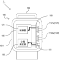
- FIG. 2 is a diagram showing the appearance of the biological information measuring device according to the first embodiment when it is worn.
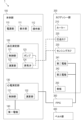
- FIG. 3 is a functional block diagram of the biological information measuring device according to the first embodiment.
- FIG. 4 is a cross-sectional view of the cuff assembly portion of the biological information measuring device according to the first embodiment.
- FIG. 5(A) is a diagram illustrating the configuration of each part of the biological information measuring device according to the first embodiment when it is worn, and
- FIG. 5(B) is a diagram specifically illustrating the arrangement of electrodes.
- FIG. 6 is a diagram showing electrical connection relationships in the biological information measuring device according to the first embodiment.
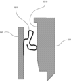
- FIG. 7 is a diagram showing electrical connections of the housing of the biological information measuring device according to the first embodiment.
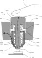
- FIG. 8 is a diagram showing electrical connections of switches of the biological information measuring device according to the first embodiment.
- FIG. 9 is a diagram illustrating the effects of the biological information measuring device according to the first embodiment.
- FIG. 10 is a diagram illustrating a measurement posture using the biological information measuring device according to the first embodiment.
- FIG. 11 is a diagram showing electrical connections of switches of a biological information measuring device according to a modification of the first embodiment.
- FIGS. 12A to 12C are diagrams illustrating the configuration of the housing of the biological information measuring device according to the second embodiment.
- FIGS. 13A to 13C are diagrams illustrating the configuration of a biological information measuring device according to the third embodiment.
- Example 1 An example of an embodiment of the present invention will be described below. However, unless otherwise specified, the dimensions, materials, shapes, and relative arrangements of the components described in this embodiment are not intended to limit the scope of the present invention.
- FIG. 1 and 2 are schematic diagrams showing the external configuration of a biological information measuring device 1 according to this embodiment.
- FIG. 3 is a functional block diagram showing the functional configuration of the biological information measuring device 1 according to this embodiment.
- the biological information measuring device 1 generally has a main body portion 100, a cuff assembly portion 200, and a belt portion 400. Electrocardiographic waveforms can be measured.
- the belt portion 400 includes a hook-and-loop fastener 411 having a hook.
- the main body portion 100 is provided with a belt loop portion 150 having an annular belt loop for inserting the belt portion 400 therethrough.
- the belt portion 400 is wrapped around the wrist T and inserted through the belt loop portion 150, and the hook-and-loop fastener 411 is attached to the belt portion 400 (a loop is formed in which the hook engages). ) to fix it in place.
- the biological information measuring device 1 also uses an FPC (Flexible 300 (not shown in FIGS. 1 and 2).
- the wrist T corresponds to the part to be measured according to the present invention
- the second electrode 241 corresponds to the second electrode according to the present invention.
- the main body portion 100 corresponds to the main body portion of the present invention
- the belt portion 400, the hook-and-loop fastener 411, and the belt loop portion 150 correspond to the fixing portion of the present invention.
- the main body section 100 includes a housing 101, a power supply section 110, a display section 111, an operation section 112, a blood pressure measurement section 120, an electrocardiogram measurement section 130, and a first electrode 140.
- the first electrode 140 includes the entire circumference of the casing 101 of the main body section 100 and operation buttons 1121a and 1122a that constitute the operation section 112, as will be described later.
- the first electrode 140 corresponds to the first electrode of the present invention
- the operation buttons 1121a and 1122a correspond to the instruction input section of the present invention.
- the power supply unit 110 is configured to include a battery that supplies power necessary for operating the device.
- the battery may be a secondary battery such as a lithium ion battery, or a primary battery.
- the display unit 111 is configured to include a display device such as a liquid crystal display, and may include an LED indicator or the like.
- the operation unit 112 specifically includes operation buttons 1121a and 1122a that are arranged on the side surface of the casing 101 of the main body 100 independently of the casing 101. A configuration in which the display unit 111 such as a touch panel display and the operation unit 112 are integrated may be used.
- the blood pressure measurement unit 120 is a functional unit that controls a cuff assembly unit 200 (described later) and measures the user's blood pressure based on information obtained thereby, and controls a control unit 121, a calculation unit 122, a pump 123, and an exhaust valve 124. Contains.
- the control unit 121 and the calculation unit 122 are configured by, for example, a CPU (Central Processing Unit), and may have a storage unit configured by a RAM (Random Access Memory), etc., although not shown.
- the control unit 121 is a functional unit that controls the blood pressure measurement unit 120, and controls the cuff pressure of the cuff assembly unit 200 via the calculation unit 122, the pump 123, etc., and controls the wrist T on which the biological information measurement device 1 is attached. Obtain information to measure the user's blood pressure from the arteries located in the.
- the calculation unit 122 measures the blood pressure value based on the information acquired in this way.
- the pump 123 and the exhaust valve 124 are mechanisms responsible for supplying and exhausting air to and from the compression cuff 220 and sensing cuff 230, which will be described later.
- the blood pressure measurement control section of the present invention includes the control section 121.
- the electrocardiogram measurement unit 130 is a functional unit that measures the electrocardiogram waveform of the user based on the potential difference between the first electrode 140 and the second electrode 241 that are in contact with the human body surface, and includes a control unit 131 and a calculation unit 132. There is.
- the control unit 131 and the calculation unit 132 are configured by the above-mentioned CPU and the like. From the viewpoint of hardware, the control section 131 and the calculation section 132 may have a common configuration with the control section 121 and the calculation section 122 of the blood pressure measurement section 120.
- the electrocardiogram measurement control section of the present invention includes the control section 131.
- both the blood pressure measurement section 120 and the electrocardiogram measurement section 130 include an AD conversion circuit, an amplifier, a filter, etc. (not shown) in addition to the above-mentioned CPU and RAM, but these are constructed using known techniques. Therefore, the explanation will be omitted.
- the cuff assembly section 200 includes a curler 210, a compression cuff 220, a sensing cuff 230, a second electrode 241, a third electrode 242, and a back plate 250.
- the curler 210 is a base member for holding the compression cuff 220.
- FIG. 4 is a cross-sectional view schematically showing the internal structure of the area surrounded by the dotted line in FIG. 1 in the cuff assembly section 200. As shown in FIG.
- the cuff assembly part 200 has a structure in which a compression cuff 220, a back plate 250, and a sensing cuff 230 are stacked in this order, with the curler 210 being the outermost part.
- the second electrode 241 and the third electrode 242 are connected to an FPC 300 provided with a conductive wire, and since this FPC 300 is connected to the control section 131 of the main body section 100 (not shown), the control section 131 and the FPC 300 are connected to each other. It functions as a wiring that electrically connects each electrode.
- the compression cuff 220 has the role of tightening the wrist T by expanding with air sent from the pump 123 and applying external pressure to an artery (not shown) existing in the wrist T.
- the sensing cuff 230 (not shown) is a fluid bag for detecting the pressure applied to the area compressed by the compression cuff 220, and when a small amount of air is contained inside the sensing cuff 230, the internal pressure is The pressure applied to the compression site is measured by detection by a meter (not shown).
- the back plate 250 (not shown) is a flexible flat member disposed between the compression cuff 220 and the sensing cuff 230, and prevents excessive bending of the sensing cuff 230 during compression by the compression cuff 220. This suppresses the pressure distribution within the sensing cuff 230.
- the second electrode 241 and the third electrode 242 are arranged near the tip 212a of the second curler part 212 of the curler 210, which is shorter in the extension direction, as described later.
- the arrangement of the second electrode 241 and the third electrode 242 is not limited to this, and they can be arranged together with the first electrode 140 at a position where they can come into contact with the body surface of the subject and detect an electrocardiographic waveform.
- the second electrode 241 functions as an electrode for electrocardiographic waveform measurement
- the third electrode 242 functions as a GND (ground) electrode for setting a reference potential.
- FIG. 5(A) showing a state in which the biological information measuring device 1 is attached to the user's wrist T.
- a compression cuff 220 is provided along the extension direction of the C-shaped curler 210 (the direction around the wrist T).
- the curler 210 has a first curler part 211 that is longer in the extension direction and a second curler part 212 that is shorter in the extension direction with respect to the position where the main body part 100 is provided.
- the first curler portion 211 extends from the main body portion 100 located on the back side of the wrist T so as to cover the artery side of the wrist T.
- the second curler part 212 extends in the circumferential direction of the wrist T on the opposite side to the first curler part 211.
- the compression cuff 220 is provided continuously from the vicinity of the end 211a of the first curler part 211 of the curler 210, along the curler 210, and also along the second curler part 212.
- the distal end portion 220b of the second curler portion 212 (in the extending direction) is located apart from the distal end portion 212a of the second curler portion 212 of the curler 210 in the extending direction.
- a second electrode 241 and a third electrode 242 are provided in the second curler portion 212 near the tip 212a of the electrode support portion 2121 that extends beyond the tip 220b of the compression cuff 220.
- FIG. 5(B) is a diagram of the second electrode 241 and the third electrode 242 seen from the inside of the electrode support part 2121 (the side that contacts the wrist T), and the second electrode 241 and the third electrode 242 are are arranged side by side in a direction perpendicular to the direction.
- An insulating separator 260 is arranged between the second electrode 241 and the third electrode 242.
- FIG. 6 is a schematic diagram illustrating electrical connections between the first electrode 140, the switch 1121, and the switch 1122 in the main body 100.
- the housing 101 houses a main circuit board 160 on which a CPU and the like constituting the blood pressure measuring section 120, the electrocardiogram measuring section 130, etc. of the main body section 100 are mounted.
- the main body 100 of the biological information measuring device 1 worn on the wrist T is placed in the casing 101 housing the main body 100 in a direction N facing the wrist T (FIGS. 2 and 5A).
- the side wall portion 1011 that surrounds the entire circumference of the main body portion 100 from the outer circumferential side in the circumferential direction C (see FIG.
- the frame section 1012 surrounding the display section 111 that is continuous with the side wall section 1022 may be similarly made of a conductive member, and the first electrode 140 may be configured to include the side wall section 1011 and the frame section 1012.
- an operation button 1121a of the switch 1121 and an operation button 1122a of the switch 1122, which constitute the operation section 112 are arranged.
- the switches 1121 and 1122 are brought into contact with and separated from the switch board 170 via an insulating material by a user operating operation buttons 1121a and 1122a.
- This switch board 170 is electrically connected to the control section 121 and the like provided on the main circuit board 160, and receives signals from switching of the switches 1121 and 1122.
- the operation buttons 1211a and 1212a are made of a conductive member and are electrically connected to the side wall 1011, and the first electrode 140 includes the side wall 1011 and the operation buttons 1211a and 1212a.
- the main body part 100 has a substantially rectangular parallelepiped shape
- the main body part 100 has a substantially rectangular parallelepiped shape.
- the side wall portion 1011 surrounding the entire circumference of the portion 100 has a rectangular shape, but may also have a cylindrical shape that is short in the axial direction N of the main body portion 100. In this case, the side wall portion 1011 has a circular shape.
- the shape of the main body part 100 is not limited to these shapes, and the side wall part 1011 can also be configured to have an appropriate shape according to the shape of the main body part 100.
- FIG. 7 is a diagram illustrating a specific configuration of the side wall portion 1011 of the housing 101, the main circuit board 160, and the electrode connection portion 161.
- a conductive leaf spring 1611 is disposed between the inner surface 1011b of the side wall 1011 of the housing 101 and the main circuit board 160.
- the elastically deformed leaf spring 1611 is brought into pressure contact with the inner surface 1011b of the side wall 1011 and the main circuit board 160 due to its restoring force, thereby establishing an electrical connection between the side wall 1011 of the housing 101 and the main circuit board 160. are doing.
- FIG. 8 is a diagram specifically explaining the electrical connection between the switch 1121 (or 1122) and the housing 101.
- the switch 1121 includes an operation button 1121a that functions as a key top, a rod-shaped plunger 1121b extending from the operation button 1121a, a housing 1121c that supports the plunger 1121b, a spring 1121d, a washer 1121e, an O-ring 1121f, a washer 1121g, a tact switch 1121h, and a switch board.
- a washer 1121g is fitted into a groove provided on the outer peripheral surface of the tip of the plunger 1121b.
- two O-rings 1121f are disposed on the distal end side of the inside of the housing 1121c to be attached to the outer periphery of the plunger 1121b.
- a washer 1121e is arranged on the base end side of the O-ring 1121f to support the distal end side of a spring 1121d wound around the outer periphery of the plunger 1121b.
- the base end side of the spring 1121d is supported by the operation button 1121a.
- the housing 1121c is fixed to the switch hole 101a of the casing 101.
- the operation button 1121a, the plunger 1121b, the washer 1121g, and the housing 1121c are made of conductive members. Thereby, the user's finger F touching the operation button 11121a and the side wall portion 1011 of the housing 101 are electrically connected by the plunger 1121b, the washer 1121g, and the housing 1121c.
- the electrical conduction path from the user's finger F to the side wall portion 1011 of the housing 101 is shown by a broken line.
- the operation buttons 1121a and 1122a function as the first electrode 140, so that when the user touches the switch 1121 or 1122 together with the housing 101, as shown in FIG. Also, the contact surface between the user's finger F and the first electrode 140 can be stabilized.
- the cuff assembly portion 200 and the belt portion 400 are wrapped around the wrist T with the main body portion 100 facing toward the back of the hand. Then, the belt section 400 is passed through the belt loop section 150 and then folded back, and the hook-and-loop fastener 411 of the belt section 400 is pasted to an arbitrary position on the belt section 400, and the biological information measuring device 1 is attached to the wrist T and fixed. do. At this time, the sensing cuff 230 is worn so as to be located on the palm side of the wrist T.
- the start of blood pressure measurement is instructed. Specifically, by injecting air into the compression cuff 220 and inflating it, the wrist T (artery) is compressed, the artery is occluded and blood flow is temporarily stopped, and then the air is gradually expelled from the compression cuff 220.
- the cuff 230 contracts to release the pressure and restore the blood flow in the artery, and the sensing cuff 230 measures the pressure at this time. That is, blood pressure measurement is performed using the so-called oscillometric method.
- the second electrode 241 and the third electrode 242 are in contact with the surfaces T1 and T2 of the wrist T (see FIG. 5(A)). It is in a state of being forced (pressed). Therefore, with the finger on which the biological information measuring device 1 is not attached, the so-called I-lead method is used to measure the potential difference between the first electrode 140 and the second electrode 241 provided on the casing 101 of the main body 100. It is possible to measure the electrocardiogram waveform.
- the finger F on which the biological information measuring device 1 is not attached corresponds to the first part of the present invention
- the surface T1 of the wrist T, which is different from the finger F corresponds to the second part of the present invention.
- the biological information measuring device 1 it is possible to measure blood pressure values and electrocardiographic waveforms simultaneously and accurately with a portable device that is worn on the wrist T.
- FIG. 11 is a diagram illustrating a modification of the electrical connection between the switch 1121 (or 1122) and the housing 101.
- the configuration of the switch 1121 is the same as in the first embodiment, and includes an operation button 1121a, a rod-shaped plunger 1121b extending from the operation button 1121a, a housing 1121c that supports the plunger 1121b, a spring 1121d, a washer 1121e, an O-ring 1121f, a washer 1121g, and a tactile member.
- a switch 1121h and a switch board 170 are included.
- a groove 101c is provided in the switch hole 1011a of the side wall 1011 of the housing 101 at a position facing the side surface of the operation button 1121a, and an electrode connection plate spring 180 made of a conductive material is disposed. .
- the elastically deformed electrode connection portion leaf spring 180 is brought into pressure contact with the housing 101 and the operation button 1121a due to its restoring force, thereby establishing an electrical connection between the operation button 1121a and the side wall portion 1011 of the housing 101.
- the user's finger F touching the operation button 1121a and the side wall portion 1011 of the housing 101 are electrically connected by the electrode connecting portion plate spring 180.
- FIG. 11 the electrically conductive path from the user's finger F to the housing 101 is shown by a broken line.
- FIG. 12 is a diagram of the biological information measuring device 2 according to the second embodiment viewed from the front of the display unit 111.
- the same components as the biological information measuring device 1 according to the first embodiment are designated by the same reference numerals, and detailed description thereof will be omitted.
- the biological information measuring device 2 has the same configuration as the biological information measuring device 1 according to the first embodiment except for the shape of the housing 102.
- the first electrode 140 is arranged at least in the axial direction N (see FIGS. 2 and 5(A)) of the main body 100 of the biological information measuring device 1 worn on the wrist T, facing the wrist T.
- the main body part 100 is configured to include at least a side wall part 1021 that surrounds the entire circumferential direction of the main body part 100 from the outer circumferential side in the circumferential direction C (see FIG. 2). As shown in FIG.
- the housing 102 of the biological information measuring device 2 has a side wall portion 1021a provided with operation buttons 1211 and 1212, and a side wall portion 1021b opposing the side wall portion 1021a, which is located at the center in the longitudinal direction.
- the housing 102 has a curved surface that is convex inward, and both side walls 1021a and 1021b of the housing 102 have a constricted shape. That is, the side wall portion 1021 of the biological information measuring device 2 is arranged in the circumferential direction C (see FIG. 2 ) has side wall portions 1021a and 1021b that are convex toward the inner circumferential side.
- the curved shapes of the side wall portions 1021a and 1021b are not limited to the shape shown in FIG. 12(A).
- the side wall portions 1021a and 1021b correspond to the concave side wall portion of the present invention.
- the user can touch both side walls 1021 and 1022 of the casing 102 with the thumb F1 and index finger F2 of the right hand.
- the thumb F1 and index finger F2 are unlikely to shift, and the contact surfaces between the fingers and the housing 102 and the switches 1121 and 1122 are stabilized.
- the position of the finger is not limited.
- the user touches the side walls 1021 and 1022 of the housing 102 with the thumb F1 and index finger F2 of the right hand the user can also touch them with the pad of the thumb F1 and the pad of the index finger F2, as shown in FIG. 12(B).
- the pad of the thumb F1 and the second joint of the index finger F2 can be touched.
- the user can touch the housing 102 in various ways, and by limiting the position where the user touches the housing 102, force is reduced.
- the side wall portion 1021 of the housing 102 is provided with side wall portions 1021a and 1021b having a constricted shape.
- the surrounding circumferential center portion is formed into a curved shape convex toward the inner circumferential side, fine irregularities may be formed on the entire side wall portion 1021 or a portion thereof.
- the uneven portion increases the frictional resistance with the user's finger F, so the finger F becomes difficult to slip on the first electrode 140 including the side wall portion 1021, and the contact state between the finger F and the first electrode 140 is stabilized. .
- fine irregularities may be formed on the surfaces of the operation buttons 1121a and 1122a.
- the uneven portion may be formed by alternately arranging concave portions and convex portions in the circumferential direction C like a bezel of a wristwatch, or may be formed by roughening the surface of the side wall portion 1021, and the structure of the uneven portion may be can be selected as appropriate.
- FIG. 13(A) is a diagram of the biological information measuring device 3 according to the third embodiment viewed from the front of the display unit 111.
- the same components as the biological information measuring device 1 according to the first embodiment are designated by the same reference numerals, and detailed description thereof will be omitted.
- the biological information measuring device 3 according to Example 3 has the same configuration as the biological information measuring device 1 according to Example 1, except for the configuration of the first electrode 140 and the operation button.
- the first electrode 140 is arranged at least in the direction N (FIGS. 2 and 5) of the main body 100 of the biological information measuring device 3 attached to the wrist T, facing the wrist T (see FIGS. 2 and 5).
- the main body part 100 is configured to include at least a side wall part 1031 that surrounds the entire circumferential direction of the main body part 100 from the outer circumferential side in the circumferential direction C (see FIG. 2) when the axial direction is (see A).
- a side wall portion 1031 included in the housing 103 functions as the first electrode 140 and also functions as an operation button.
- a side wall portion 1031 forming a bezel portion surrounding the display portion 111 is configured.
- This side wall portion 1031 is made of a conductive member and has a function as the first electrode 140. Further, this side wall portion 1031 is attached as a movable portion to the housing body 1032 in order to function as an operation button.
- a side wall portion 1031 surrounding the display portion 111 is supported so as to be able to reciprocate with respect to a rectangular parallelepiped-shaped housing body 1032 to which a belt portion 400 is attached. There is. By pushing the side wall portion 1031 into the housing body 1032 in the direction of the arrow, the side wall portion 1031 functions as an operation button.
- a side wall portion 1033 bent from the frame portion 1012 of the display portion 111 and formed to cover the side surface of the housing body 1034 is a flange-shaped cover. It is supported in a reciprocating manner by the housing body 1034 from which the portion 1034a is exposed.
- the side wall portion 1033 is made of a conductive member and has a function as the first electrode 140. By pushing the side wall portion 1033 into the housing body 1034 in the direction of the arrow, the side wall portion 1033 functions as an operation button. That is, the side wall parts 1031 and 1033 are the side wall parts of the present invention, and correspond to an integrally provided instruction input section.
- the side walls 1031 and 1033 of the biological information measuring device 3 according to the third embodiment can also have the concave shape according to the second embodiment.
- Biological information measuring device 100 Main body part 101... Housing 121, 131... Control part 1011. Side wall part 140... First electrode 241... Second electrode 400... Band part 1121a, 1122a. ⁇ Manual operation button
Landscapes
- Health & Medical Sciences (AREA)
- Life Sciences & Earth Sciences (AREA)
- Cardiology (AREA)
- Engineering & Computer Science (AREA)
- Heart & Thoracic Surgery (AREA)
- Surgery (AREA)
- Biophysics (AREA)
- Pathology (AREA)
- Veterinary Medicine (AREA)
- Biomedical Technology (AREA)
- Public Health (AREA)
- Medical Informatics (AREA)
- Molecular Biology (AREA)
- Physics & Mathematics (AREA)
- Animal Behavior & Ethology (AREA)
- General Health & Medical Sciences (AREA)
- Physiology (AREA)
- Vascular Medicine (AREA)
- Pulmonology (AREA)
- Signal Processing (AREA)
- Ophthalmology & Optometry (AREA)
- Measuring Pulse, Heart Rate, Blood Pressure Or Blood Flow (AREA)
- Measurement And Recording Of Electrical Phenomena And Electrical Characteristics Of The Living Body (AREA)
Priority Applications (3)
| Application Number | Priority Date | Filing Date | Title |
|---|---|---|---|
| CN202380046662.XA CN119384248A (zh) | 2022-07-22 | 2023-02-13 | 生物体信息测定装置 |
| DE112023003190.8T DE112023003190T5 (de) | 2022-07-22 | 2023-02-13 | Messvorrichtung für biometrische informationen |
| US18/990,341 US20250120593A1 (en) | 2022-07-22 | 2024-12-20 | Biometric information measurement device |
Applications Claiming Priority (2)
| Application Number | Priority Date | Filing Date | Title |
|---|---|---|---|
| JP2022117329A JP2024014478A (ja) | 2022-07-22 | 2022-07-22 | 生体情報測定装置 |
| JP2022-117329 | 2022-07-22 |
Related Child Applications (1)
| Application Number | Title | Priority Date | Filing Date |
|---|---|---|---|
| US18/990,341 Continuation US20250120593A1 (en) | 2022-07-22 | 2024-12-20 | Biometric information measurement device |
Publications (1)
| Publication Number | Publication Date |
|---|---|
| WO2024018667A1 true WO2024018667A1 (ja) | 2024-01-25 |
Family
ID=89617557
Family Applications (1)
| Application Number | Title | Priority Date | Filing Date |
|---|---|---|---|
| PCT/JP2023/004821 Ceased WO2024018667A1 (ja) | 2022-07-22 | 2023-02-13 | 生体情報測定装置 |
Country Status (5)
| Country | Link |
|---|---|
| US (1) | US20250120593A1 (https=) |
| JP (1) | JP2024014478A (https=) |
| CN (1) | CN119384248A (https=) |
| DE (1) | DE112023003190T5 (https=) |
| WO (1) | WO2024018667A1 (https=) |
Cited By (1)
| Publication number | Priority date | Publication date | Assignee | Title |
|---|---|---|---|---|
| WO2025164035A1 (ja) * | 2024-01-31 | 2025-08-07 | オムロンヘルスケア株式会社 | 生体情報測定装置 |
Citations (4)
| Publication number | Priority date | Publication date | Assignee | Title |
|---|---|---|---|---|
| US20190072912A1 (en) * | 2017-09-05 | 2019-03-07 | Apple Inc. | Wearable Electronic Device with Electrodes for Sensing Biological Parameters |
| CN211022649U (zh) * | 2019-07-29 | 2020-07-17 | 潍坊歌尔电子有限公司 | 具有6导联心电记录功能的腕带类电子产品 |
| CN113876329A (zh) * | 2020-07-03 | 2022-01-04 | 华为技术有限公司 | 一种心电检测装置 |
| US20220054080A1 (en) * | 2020-08-18 | 2022-02-24 | Fitbit, Inc. | Detection and Response to Arousal Activations |
-
2022
- 2022-07-22 JP JP2022117329A patent/JP2024014478A/ja active Pending
-
2023
- 2023-02-13 DE DE112023003190.8T patent/DE112023003190T5/de active Pending
- 2023-02-13 WO PCT/JP2023/004821 patent/WO2024018667A1/ja not_active Ceased
- 2023-02-13 CN CN202380046662.XA patent/CN119384248A/zh active Pending
-
2024
- 2024-12-20 US US18/990,341 patent/US20250120593A1/en active Pending
Patent Citations (4)
| Publication number | Priority date | Publication date | Assignee | Title |
|---|---|---|---|---|
| US20190072912A1 (en) * | 2017-09-05 | 2019-03-07 | Apple Inc. | Wearable Electronic Device with Electrodes for Sensing Biological Parameters |
| CN211022649U (zh) * | 2019-07-29 | 2020-07-17 | 潍坊歌尔电子有限公司 | 具有6导联心电记录功能的腕带类电子产品 |
| CN113876329A (zh) * | 2020-07-03 | 2022-01-04 | 华为技术有限公司 | 一种心电检测装置 |
| US20220054080A1 (en) * | 2020-08-18 | 2022-02-24 | Fitbit, Inc. | Detection and Response to Arousal Activations |
Cited By (1)
| Publication number | Priority date | Publication date | Assignee | Title |
|---|---|---|---|---|
| WO2025164035A1 (ja) * | 2024-01-31 | 2025-08-07 | オムロンヘルスケア株式会社 | 生体情報測定装置 |
Also Published As
| Publication number | Publication date |
|---|---|
| US20250120593A1 (en) | 2025-04-17 |
| CN119384248A (zh) | 2025-01-28 |
| JP2024014478A (ja) | 2024-02-01 |
| DE112023003190T5 (de) | 2025-04-30 |
Similar Documents
| Publication | Publication Date | Title |
|---|---|---|
| US20230070192A1 (en) | Wearable Device | |
| US9782098B2 (en) | Cardiovascular monitoring device | |
| TWI631930B (zh) | 生理訊號感測裝置 | |
| CN203436321U (zh) | 心血管检测装置 | |
| US20250120593A1 (en) | Biometric information measurement device | |
| CN102631190B (zh) | 心血管监测装置 | |
| TWI624246B (zh) | 血壓量測裝置及其方法 | |
| US20240197189A1 (en) | Biological information measurement device | |
| JP7525064B2 (ja) | 生体情報測定装置 | |
| US20160235307A1 (en) | Cardiovascular monitoring device | |
| CN212694262U (zh) | 可穿戴设备 | |
| CN111093496A (zh) | 生物信息测定器 | |
| JP2024014478A5 (https=) | ||
| JP7107822B2 (ja) | 血圧計用カフ | |
| TW201827004A (zh) | 壓力感測器及血壓量測裝置 | |
| US20240197252A1 (en) | Biological information measurement device | |
| JP2025118443A (ja) | 生体情報測定装置 | |
| US20240041338A1 (en) | Cuff cover | |
| US20260041327A1 (en) | Biological information measurement device | |
| CN112426140A (zh) | 生命体征传感系统 | |
| KR20170141336A (ko) | 생체 신호 측정용 착용형 밴드 장치 | |
| WO2024042749A1 (ja) | 生体情報測定装置 | |
| JP2024002183A (ja) | 生体情報測定装置、生体情報測定装置の制御方法及びプログラム |
Legal Events
| Date | Code | Title | Description |
|---|---|---|---|
| 121 | Ep: the epo has been informed by wipo that ep was designated in this application |
Ref document number: 23842605 Country of ref document: EP Kind code of ref document: A1 |
|
| DPE1 | Request for preliminary examination filed after expiration of 19th month from priority date (pct application filed from 20040101) | ||
| WWE | Wipo information: entry into national phase |
Ref document number: 202417092669 Country of ref document: IN |
|
| WWE | Wipo information: entry into national phase |
Ref document number: 202380046662.X Country of ref document: CN |
|
| WWP | Wipo information: published in national office |
Ref document number: 202380046662.X Country of ref document: CN |
|
| WWE | Wipo information: entry into national phase |
Ref document number: 112023003190 Country of ref document: DE |
|
| WWP | Wipo information: published in national office |
Ref document number: 112023003190 Country of ref document: DE |
|
| 122 | Ep: pct application non-entry in european phase |
Ref document number: 23842605 Country of ref document: EP Kind code of ref document: A1 |