WO2024018604A1 - 端末 - Google Patents
端末 Download PDFInfo
- Publication number
- WO2024018604A1 WO2024018604A1 PCT/JP2022/028389 JP2022028389W WO2024018604A1 WO 2024018604 A1 WO2024018604 A1 WO 2024018604A1 JP 2022028389 W JP2022028389 W JP 2022028389W WO 2024018604 A1 WO2024018604 A1 WO 2024018604A1
- Authority
- WO
- WIPO (PCT)
- Prior art keywords
- csi
- resource
- sbfd
- resources
- band
- Prior art date
- Legal status (The legal status is an assumption and is not a legal conclusion. Google has not performed a legal analysis and makes no representation as to the accuracy of the status listed.)
- Ceased
Links
Images











Classifications
-
- H—ELECTRICITY
- H04—ELECTRIC COMMUNICATION TECHNIQUE
- H04W—WIRELESS COMMUNICATION NETWORKS
- H04W24/00—Supervisory, monitoring or testing arrangements
- H04W24/10—Scheduling measurement reports ; Arrangements for measurement reports
-
- H—ELECTRICITY
- H04—ELECTRIC COMMUNICATION TECHNIQUE
- H04W—WIRELESS COMMUNICATION NETWORKS
- H04W72/00—Local resource management
- H04W72/04—Wireless resource allocation
- H04W72/044—Wireless resource allocation based on the type of the allocated resource
- H04W72/0446—Resources in time domain, e.g. slots or frames
-
- H—ELECTRICITY
- H04—ELECTRIC COMMUNICATION TECHNIQUE
- H04W—WIRELESS COMMUNICATION NETWORKS
- H04W72/00—Local resource management
- H04W72/04—Wireless resource allocation
- H04W72/044—Wireless resource allocation based on the type of the allocated resource
- H04W72/0453—Resources in frequency domain, e.g. a carrier in FDMA
-
- H—ELECTRICITY
- H04—ELECTRIC COMMUNICATION TECHNIQUE
- H04W—WIRELESS COMMUNICATION NETWORKS
- H04W72/00—Local resource management
- H04W72/20—Control channels or signalling for resource management
Definitions
- the present disclosure relates to a terminal that communicates with a base station.
- 3rd Generation Partnership Project 3rd Generation Partnership Project, registered trademark
- 5G New Radio (NR) or Next Generation (NG)
- NG Next Generation
- 5G New Radio
- NG Next Generation
- 6G 6th Generation
- Non-Patent Document 1 XDD (Cross Division Duplex) is a new duplex method that enables simultaneous use of downlink (DL) and uplink (UL) within a time division duplex (TDD) band carrier.
- SBFD Sub-Band non-overlapping full duplex
- DL band DL frequency resources
- UL band UL frequency resources
- the introduction of the new duplex method enables simultaneous use of the DL band and UL band, which can alleviate potential inter-link interference with adjacent carriers, and is expected to further improve communication capacity and communication throughput.
- a DL band and a UL band may exist in the same symbol or slot. Therefore, resources for DL reference signals such as CSI-RS (Channel State Information-Reference Signal) allocated to a predetermined frequency band may overlap with symbols or slots on the UL band in the duplex band. . Therefore, when a terminal communicates with a base station using a new duplex method, the question is how to control the UE's behavior when such duplication is allowed or not, for example, the behavior related to channel state measurement. This could be a problem.
- CSI-RS Channel State Information-Reference Signal
- the following disclosure has been made in view of this situation, and describes a terminal that can measure channel conditions suitable for communicating with a base station using an extended duplex method such as XDD or SBFD. For the purpose of providing.
- One aspect of the present disclosure is to receive a DL reference signal set at a base station that performs communication in a manner in which DL bands and UL bands are allocated in a non-overlapping manner in the frequency direction within a specified time based on time division duplexing.
- a receiving unit an operation related to measuring a channel state in a case where duplication of resources for the DL reference signal in the UL band at or within the specified time is allowed, and a channel state in a case where the duplication is not allowed;
- the terminal includes a control unit that controls operations related to the measurement of the information.
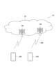
- FIG. 1 is an overall schematic configuration diagram of a wireless communication system 10 according to this embodiment.
- FIG. 2 is a diagram showing a configuration example of a radio frame, subframe, and slot used in the radio communication system 10.
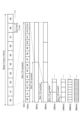
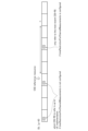
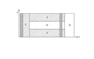
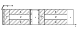
- FIG. 3 is a diagram for explaining a configuration example of the XDD and SBFD.
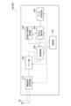
- FIG. 4 is a functional block configuration diagram of the gNB 100 and the UE 200.
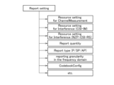
- FIG. 5 is a diagram showing an example of report settings (ReportConfig).
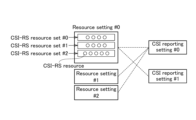
- FIG. 6 is a diagram illustrating an example of resource settings.
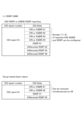
- FIG. 7 is a diagram showing types of reports and resources.
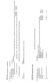
- FIG. 8 is a diagram showing an example of the amount of CSI reports.
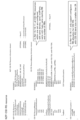
- FIG. 9 is a diagram showing the contents of the CSI report.
- FIG. 1 is an overall schematic configuration diagram of a wireless communication system 10 according to this embodiment.
- FIG. 2 is a diagram showing a configuration example of a radio frame, subframe, and slot used in the radio communication system 10.
- FIG. 3 is
- FIG. 10 is a diagram illustrating a configuration example of information elements of CSI-RS resource settings and resource sets.
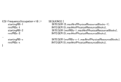
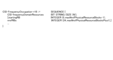
- FIG. 11 is a diagram illustrating a configuration example of information elements of the NZP-CSI-RS resource.
- FIG. 12 is a diagram showing CSI-RS resources referenced by the UE 200.
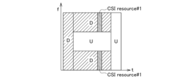
- FIG. 13 is a diagram for explaining problems in CSI measurement using extended duplex methods such as XDD and SBFD.
- FIG. 14 is a diagram for explaining the problem of overlapping DL reference signal resources when an extended duplex method such as XDD or SBFD is applied.
- FIG. 15 is a diagram showing an example of a communication sequence regarding CSI-RS settings and CSI report reporting.
- FIG. 16 is a diagram for explaining operation example 1.
- FIG. 17 is a diagram for explaining the combination of Cond-2A and Cond-2B in operation example 1.
- FIG. 18 is a diagram for explaining Cond-2C in operation example 1.
- FIG. 19 is a diagram for explaining Cond-2C in operation example 1.
- FIG. 20 is a diagram for explaining the operation of option 2 in operation example 1.
- FIG. 21 is a diagram for explaining the operation of option 2 in operation example 1.
- FIG. 22 is a diagram for explaining the operation of option 2-2 in operation example 1.
- FIG. 23 is a diagram for explaining the operation of option 2-2 in operation example 1.
- FIG. 24 is a diagram for explaining the operation of option 2-2 in operation example 1.
- FIG. 25 is a diagram for explaining operation example 2.
- FIG. 26 is a diagram for explaining operation example 2.
- FIG. 27 is a diagram for explaining operation example 2.
- FIG. 28 is a diagram illustrating a configuration example of subband information elements in Enhancement #1 (Example 1) of Operation Example 3.
- FIG. 29 is a diagram illustrating a configuration example of subband information elements in Enhancement #1 (Example 2) of Operation Example 3.
- FIG. 30 is a diagram illustrating an example of subband settings in Enhancement #1 (Example 1) of Operation Example 3.
- FIG. 31 is a diagram illustrating a setting example of CSI-RS resources in Enhancement #3 (option 1, example 1) of operation example 3.
- FIG. 32 is a diagram illustrating a setting example of CSI-RS resources in Enhancement #3 (option 1, example 2) of operation example 3.
- FIG. 33 is a diagram illustrating a configuration example of information elements of frequency band configuration in Enhancement #4 of Operation Example 3.
- FIG. 34 is a diagram illustrating a configuration example of information elements of frequency band configuration in Enhancement #4 of Operation Example 3.
- FIG. 35 is a diagram for explaining an operation example in Enhancement #5 of operation example 3.
- FIG. 36 is a diagram for explaining problems related to operation example 4.
- FIG. 37 is a diagram for explaining the Alt2 sequence of operation example 4.
- FIG. 38 is a diagram for explaining the Alt2 sequence of operation example 4.
- FIG. 39 is a diagram for explaining the Alt3 sequence of operation example 4.
- FIG. 40 is a diagram for explaining the Alt4 sequence of operation example 4.
- FIG. 41 is a diagram illustrating an example of the hardware configuration of the gNB 100 and the UE 200.
- FIG. 42 is a diagram showing a configuration example of vehicle 2001.
- FIG. 1 is an overall schematic configuration diagram of wireless communication system 10 according to the present embodiment.
- the wireless communication system 10 is a wireless communication system according to 5G New Radio (NR), and includes a Next Generation-Radio Access Network 20 (hereinafter referred to as NG-RAN 20) and a terminal 200 (hereinafter referred to as UE200, User Equipment, UE).
- NG-RAN 20 Next Generation-Radio Access Network 20
- UE200 User Equipment
- the wireless communication system 10 may be a wireless communication system that follows a system called Beyond 5G, 5G Evolution, or 6G.
- the NG-RAN 20 includes a wireless base station 100 (hereinafter referred to as gNB 100). Note that the specific configuration of the wireless communication system 10 including the number of gNBs 100 and UEs 200 is not limited to the example shown in FIG. 1.
- the NG-RAN 20 actually includes a plurality of NG-RAN Nodes, specifically gNB 100 (or ng-eNB), and is connected to a 5G-compliant core network (5GC, not shown). Note that the NG-RAN 20 and 5GC may be simply expressed as a "network.”
- the gNB 100 is a 5G wireless base station and performs 5G wireless communication with the UE 200.
- the gNB 100 and the UE 200 use Massive MIMO (Multiple-Input Multiple-Output), which generates a highly directional antenna beam (hereinafter referred to as beam BM) by controlling radio signals transmitted from multiple antenna elements.
- Massive MIMO Multiple-Input Multiple-Output
- beam BM highly directional antenna beam
- CA carrier aggregation
- DC dual connectivity
- the gNB 100 can spatially and time-divisionally transmit a plurality of beams BM having different transmission directions (which may also be referred to simply as directions, radiation directions, coverage, etc.). Note that the gNB 100 may transmit multiple beams BM simultaneously.
- the wireless communication system 10 may support multiple frequency ranges (FR). Specifically, the following frequency ranges may be supported.
- FR1 410 MHz to 7.125 GHz
- FR2-1 24.25 GHz to 52.6 GHz
- SCS sub-carrier spacing
- BW bandwidth
- FR2-1 is higher frequency than FR1, with subcarrier spacing (SCS) of 60 or 120 kHz (may include 240 kHz) and a bandwidth (BW) of 50 to 400 MHz. good.
- SCS may be interpreted as numerology. Numerology is defined in 3GPP TS38.300 and corresponds to one subcarrier spacing in the frequency domain.
- the wireless communication system 10 also supports a frequency band higher than the frequency band of FR2-1. Specifically, the wireless communication system 10 supports frequency bands exceeding 52.6 GHz and up to 71 GHz. Such a high frequency band may be referred to as FR2-2.
- Cyclic Prefix-Orthogonal Frequency Division Multiplexing (CP-OFDM)/D with larger Sub-Carrier Spacing (SCS) Apply iscrete Fourier Transform - Spread (DFT-S-OFDM) Good too.
- CP-OFDM Cyclic Prefix-Orthogonal Frequency Division Multiplexing
- SCS Sub-Carrier Spacing
- DFT-S-OFDM iscrete Fourier Transform - Spread
- FIG. 2 shows an example of the configuration of radio frames, subframes, and slots used in the radio communication system 10.
- the symbol period may also be referred to as symbol length, time direction, time domain, or the like.
- the frequency direction may be referred to as a frequency domain, resource block, subcarrier, BWP (Bandwidth part), or the like.
- Frequency resources may include component carriers, subcarriers, resource blocks (RBs), resource block groups (RBGs), BWPs (Bandwidth parts), and the like.
- the time resources may include symbols, slots, minislots, subframes, radio frames, DRX (Discontinuous Reception) periods, and the like.
- the number of symbols constituting one slot does not necessarily have to be 14 symbols (for example, 28 or 56 symbols). Also, the number of slots per subframe may vary depending on the SCS.
- an SSB (SS/PBCH Block) composed of a synchronization signal (SS) and a physical downlink broadcast channel (PBCH) may be used.
- SS synchronization signal
- PBCH physical downlink broadcast channel
- the SSB is periodically transmitted from the network mainly for the UE 200 to detect the cell ID and reception timing when starting communication.
- SSB is also used to measure the reception quality of each cell.
- the SSB transmission period may be defined as 5, 10, 20, 40, 80, 160 milliseconds, or the like. Note that the UE 200 for initial access may assume a transmission cycle of 20 milliseconds.
- Duplex a plurality of duplex methods
- TDD time division duplexing
- FDD frequency division duplexing
- the duplex method may be interpreted as a method for realizing simultaneous transmission and reception of downlink (DL) and uplink (UL) (duplex communication).
- the wireless communication system 10 uses another duplex method that enables simultaneous use of DL and UL, specifically XDD (Cross Division Duplex), SBFD (Sub-Band non-overlapping Full Duplex). non-overlapping full duplex) may be used.
- XDD Cross Division Duplex
- SBFD Sub-Band non-overlapping Full Duplex
- FIG. 3 is a diagram for explaining a configuration example of the XDD and SBFD.
- XDD enables simultaneous use of DL and UL within a carrier (CC) of the TDD band. Using the central portion of frequency resources within a UL carrier can avoid or mitigate potential Cross Link Interference (CLI) with adjacent carriers.
- XDD may also be called a type of full duplex or FDD full duplex.
- DL frequency resources (DL band) and UL frequency resources (UL band) are allocated to duplex bands on the same time resource in a non-overlapping manner.
- SBFD is a method in which DL bands and UL bands are allocated in a non-overlapping manner in the frequency direction within a specified time T based on time division duplexing.
- the DL band for the specified time T is written as "DL”
- the UL band for the specified time T is written as "UL”.
- a DL band may be interpreted as a DL subband.
- UL bands may be interpreted as UL subbands.
- the time T' may be interpreted as a time region outside the specified time T.
- a Neighbor Relationship Table (NRT) and a Neighbor Cell R (NCRT) are applied to handover (HO) of the UE 200 to another cell and manage identification information (CGI: Cell Global Identifier) of neighboring cells. elation Table) and ) may be used.
- the contents of the NRT may be manually set in advance, but an ANR (Automatic Neighbor Relation) function that automatically associates neighboring cell information (CGI) may be introduced.
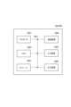
- FIG. 4 is a functional block configuration diagram of the gNB 100 and the UE 200.
- the UE 200 includes a radio signal transmission/reception section 210, an amplifier section 220, a modulation/demodulation section 230, a control signal/reference signal processing section 240, an encoding/decoding section 250, a data transmission/reception section 260, and a control section. 270.
- FIG. 4 shows the functional block configuration of the UE 200 (gNB 100), and please refer to FIG. 41 for the hardware configuration.
- the radio signal transmitting/receiving unit 210 of the UE 200 transmits and receives radio signals according to NR.
- the wireless signal transmitting/receiving unit 210 uses Massive MIMO, which generates a highly directional beam by controlling radio (RF) signals transmitted from multiple antenna elements, and a carrier that uses multiple component carriers (CC) in a bundle. It is possible to support aggregation (CA), dual connectivity (DC) in which communication is performed simultaneously between the UE 200 and each of two NG-RAN nodes, and the like.
- Massive MIMO which generates a highly directional beam by controlling radio (RF) signals transmitted from multiple antenna elements, and a carrier that uses multiple component carriers (CC) in a bundle.
- CC component carriers
- CA aggregation
- DC dual connectivity
- the amplifier unit 220 of the UE 200 is configured by a PA (Power Amplifier)/LNA (Low Noise Amplifier) or the like.
- Amplifier section 220 amplifies the signal output from modulation/demodulation section 230 to a predetermined power level. Furthermore, the amplifier section 220 amplifies the RF signal output from the radio signal transmitting/receiving section 210.
- the modulation/demodulation unit 230 of the UE 200 performs data modulation/demodulation, transmission power setting, resource block allocation, etc. for each predetermined communication destination (gNB 100, etc.).
- the modulation/demodulation section 230 performs Cyclic Prefix-Orthogonal Frequency Division Multiplexing (CP-OFDM)/Discrete Fourier Transform-S pread (DFT-S-OFDM) may be applied.
- CP-OFDM Cyclic Prefix-Orthogonal Frequency Division Multiplexing
- DFT-S-OFDM Discrete Fourier Transform-S pread
- DFT-S-OFDM may be used not only for uplink (UL) but also for downlink (DL).
- the control signal/reference signal processing unit 240 of the UE 200 executes processing related to various control signals transmitted and received by the UE 200 and processing related to various reference signals transmitted and received by the UE 200.
- the control signal/reference signal processing unit 240 of the gNB 100 executes processing related to various control signals transmitted and received by the gNB 100 and processing related to various reference signals transmitted and received by the gNB 100.
- control signal/reference signal processing unit 240 of the UE 200 receives various control signals transmitted from the gNB 100 via a predetermined control channel, for example, a radio resource control layer (RRC) control signal. Further, the control signal/reference signal processing unit 240 of the UE 200 transmits various control signals to the gNB 100 via a predetermined control channel.
- a predetermined control channel for example, a radio resource control layer (RRC) control signal.
- RRC radio resource control layer
- the control signal/reference signal processing unit 240 of the UE 200 processes reference signals (RS) such as Demodulation Reference Signal (DMRS) and Phase Tracking Reference Signal (PTRS). ).
- RS reference signals
- DMRS Demodulation Reference Signal
- PTRS Phase Tracking Reference Signal
- DMRS is a reference signal (pilot signal) known between a terminal-specific base station and the terminal for estimating a fading channel used for data demodulation.
- PTRS is a terminal-specific reference signal for the purpose of estimating phase noise, which is a problem in high frequency bands.
- reference signals include Channel State Information-Reference Signal (CSI-RS), Sounding Reference Signal (SRS), and Posit for location information.
- CSI-RS Channel State Information-Reference Signal
- SRS Sounding Reference Signal
- PRS Posit for location information
- the channels include a control channel and a data channel.
- the control channels include PDCCH, PUCCH (Physical Uplink Control Channel), RACH (Random Access Channel, Random Access Radio Network T Downlink Control Information (DCI) including temporary Identifier (RA-RNTI), Physical Broadcast Channel (PBCH), etc. may be included.
- PDCCH Physical Uplink Control Channel
- RACH Random Access Radio Network T Downlink Control Information
- DCI Random Access Radio Network T Downlink Control Information
- RA-RNTI temporary Identifier
- PBCH Physical Broadcast Channel
- data channels include PDSCH, PUSCH (Physical Uplink Shared Channel), and the like.
- Data may refer to data transmitted over a data channel.
- the control signal/reference signal processing unit 240 of the UE 200 may receive a DL reference signal set by a base station that communicates using a predetermined communication method.
- the control signal/reference signal processing section 240 of the UE 200 constitutes a receiving section.
- the predetermined communication method may include a method of communicating with the base station using an extended duplex method. Specifically, it may include a system in which DL bands and UL bands are allocated non-overlappingly in the frequency direction within a specified time based on time division duplexing, such as XDD and SBFD.
- DL reference signals may include channel state information reference signals (CSI-RS), DMRS, PTRS, SRS, PRS, etc.
- CSI-RS channel state information reference signals
- DMRS DMRS
- PTRS PTRS
- SRS SRS
- PRS PRS
- the encoding/decoding unit 250 of the UE 200 (gNB 100) performs data division/concatenation, channel coding/decoding, etc. for each predetermined communication destination (gNB 100 or other gNB).
- the encoding/decoding unit 250 divides the data output from the data transmitting/receiving unit 260 into predetermined sizes, and performs channel coding on the divided data. Furthermore, the encoding/decoding section 250 decodes the data output from the modulation/demodulation section 230 and concatenates the decoded data.
- the data transmission/reception unit 260 of the UE 200 executes transmission and reception of Protocol Data Units (PDUs) and Service Data Units (SDUs). Specifically, the data transmitting/receiving unit 260 transmits PDUs/SDUs in multiple layers (such as a medium access control layer (MAC), a radio link control layer (RLC), and a packet data convergence protocol layer (PDCP)). Assemble/disassemble etc. Further, the data transmitter/receiver 260 performs data error correction and retransmission control based on hybrid ARQ (Hybrid automatic repeat request).
- PDUs Protocol Data Units
- SDUs Service Data Units
- the data transmitting/receiving unit 260 transmits PDUs/SDUs in multiple layers (such as a medium access control layer (MAC), a radio link control layer (RLC), and a packet data convergence protocol layer (PDCP)). Assemble/disassemble etc. Further, the data transmitter/receiver 260 performs data error
- the control unit 270 controls each functional block that configures the UE 200.
- the control unit 270 of the UE 200 may perform CSI measurement and CSI reporting depending on symbols and/or slots.
- control unit 270 may perform CSI measurement and CSI reporting according to the SBFD symbols and/or SBFD slots based on the report settings and resource settings. More specifically, the control unit 270 performs CSI measurement according to the SBFD symbol and/or SBFD slot based on the CSI-RS included in the DL reference signal received by the control signal/reference signal processing unit 240. conduct. Further, the control unit 270 may transmit (report) a CSI report including a CSI measurement result to the gNB 100.
- FIG. 5 is a diagram showing an example of report settings (ReportConfig).
- the report settings include information that sets how the UE 200 performs the CSI report, for example, resource settings for Channel Measurement, resource settings for interference measurement (CSI-IM, NZP-CSI-RS), report quantity, Includes report type (P/SP/AP), etc.
- FIG. 6 is a diagram illustrating an example of resource settings.
- the resource settings include information regarding CSI-RS resources used for CSI measurement. For example, a specific resource configuration (#0) includes a plurality of CSI-RS resource sets (#0, #1, #2). Each CSI-RS resource set includes a plurality of CSI-RS resources. Note that configuration examples of CSI-RS resource settings, CSI-RS resource sets, and NZP-CSI-RS information elements are shown in FIGS. 10 and 11.
- FIG. 7 is a diagram showing types of reports and resources.
- the UE 200 may transmit the CSI report to the network periodically, semi-permanently, or aperiodically, depending on the parameters of the CSI report settings. Further, the resource settings may also be set periodically, semi-permanently, or aperiodically.
- FIG. 8 is a diagram showing an example of the amount of CSI reports. The CSI report amount may be interpreted as the type of information reported by the UE 200.
- the CSI report amount is CRI-RI-PMI-CQI, CRI-RI-i1, CRI-RI-i1-CQI, CRI-RI-CQI, CRI-RI-LI-PMI-CQI, CRI-RSRP, SSB - May include RSRP, CRI-SINR-r16, SSB-SINR-r16, etc.
- - CRI CSI-RS Resource Index
- - RI CSI-RS Resource Index
- - RI CSI-RS Resource Index
- - RI Rank Indicator
- - PMI Precoding Matrix Indicator
- -CQI Channel Quality Indicator
- - i1 may be interpreted as one wideband indication for the entire CSI report band.
- LI Layer Indicator
- RI reported Rank Indicator
- -RSRP Reference Signal Receive Power
- SSB SS/PBCH Block
- SINR Signal to Interference plus Noise Ratio
- FIG. 9 is a diagram showing the contents of the CSI report.
- the CSI report may include the reception power of the received signal (L1-RSRP), the reception quality of the signal (SINR), and the like.
- SSBRI SSB Resource Indicator
- FIG. 9 may be interpreted as a CSI measurement resource ID.
- FIG. 12 is a diagram showing CSI-RS resources referenced by the UE 200.
- the UE 200 sets the CSI reference associated with the CSI resource setting.
- source for example, see 3GPP TS 38.211 [4]
- CSI- Based only on the occasion of the RS, channel measurements may be derived to calculate the CSI value reported in uplink slot n.
- the UE 200 sets the CSI reference res associated with the CSI resource setting.
- source for example, see 3GPP TS 38.211 [4]
- the latest Only the NZP CSI-RS (non-zero-power CSI-RS) occasion may be selected.
- the UE 200 may derive channel measurements for calculating the CSI value reported in uplink slot n based on the selected NZP CSI-RS occasion.
- the control unit 270 of the UE 200 allows duplication of resources for DL reference signals within the specified time T, or when allowing duplication of resources for DL reference signals in the UL band within the specified time T. Operations related to channel state measurement and operations related to channel state measurement in a case where the duplication is not allowed may be controlled.
- control unit 270 of the UE 200 controls the channel state in a case where duplication of CSI-RS resources in subband non-overlapping full-duplex (SBFD) symbols and/or SBFD slots is not allowed. Operations related to measurement may be controlled. Furthermore, the control unit 270 of the UE 200 may control operations related to channel state measurement in a case where duplication of CSI-RS resources in the UL band in an SBFD symbol is not allowed.
- SBFD subband non-overlapping full-duplex
- control unit 270 of the UE 200 is concerned with channel state measurement in the case of allowing duplication of CSI-RS resources in subband non-overlapping full duplex (SBFD) symbols and/or SBFD slots. Movement may be controlled. Furthermore, the control unit 270 of the UE 200 may control operations related to channel state measurement when duplication of CSI-RS resources in the UL band in the SBFD symbol is allowed. Details of operations related to channel state measurement will be described later.
- SBFD subband non-overlapping full duplex
- the prescribed time T may include XDD symbols/slots, SBFD symbols/slots, etc.
- Resources for DL reference signals may include CSI-RS occasions.
- CSI-RS occasion may be abbreviated as "CO”.
- CO may be interpreted as a CSI-RS resource in the time direction, or may be interpreted as a CSI-RS resource in the time direction and frequency direction.
- the UL band within the specified time T may be interpreted as a UL subband or UL frequency resource included in a duplex band on the same time resource in XDD or SBFD.
- the control signal/reference signal processing unit 240 of the UE interprets the respective frequency band configurations (for example, differences in startPRB and/or nrofPrbs) differently in cases where the CSI-RS resource overlaps with the SBFD symbol and when the CSI-RS resource does not overlap with the SBFD symbol. may be applied to perform operations related to measuring channel conditions.
- the control signal/reference signal processing unit 240 of the UE 200 uses the frequency band configuration of 3GPP Release 15, Release 16, and/or Release/17.
- CSI measurement and CSI reporting may be performed by inheriting the interpretation in .
- the control signal/reference signal processing unit 240 of the UE 200 performs CSI measurement and CSI report, assuming that the CSI-RS frequency band is within the DL subband. You may do so.
- the control signal/reference signal processing unit 240 of the gNB 100 may adjust resource settings for DL reference signals in order to avoid duplication of resources for DL reference signals in the UL band at or within the specified time T.
- control signal/reference signal processing unit 240 of the gNB 100 may non-contiguously set a plurality of resource blocks used for measuring channel state information in the DL reference signal resource.
- control signal/reference signal processing unit 240 of the gNB 100 may narrowband the RB allocation of the CSI-RS. Specifically, the control signal/reference signal processing unit 240 of the gNB 100 may set the number (nrofRBs) of radio resource blocks (RB) to a value smaller than a predetermined value (for example, 24). nrofRBs may be interpreted as the number of PRBs spanned by the CSI resource, and may be interpreted as the bandwidth of the CSI report band. An RB may be interpreted as the minimum unit of radio resources on which frequency scheduling is performed.
- the control signal/reference signal processing unit 240 of the gNB 100 may allocate the resources of the DL reference signal to the prescribed time T and the time domain outside the prescribed time T (time T'), and may allocate the resources of the DL reference signal to Resources may be allocated to each of the DL band within the specified time T and the DL band in the time domain (time T') outside the specified time T.
- the control signal/reference signal processing unit 240 of the gNB 100 may set different frequency band configurations for the CSI-RS resource depending on whether the CSI-RS occurrence overlaps with the SBFD symbol/slot or not. Note that since the gNB 100 sets a DL/UL (non-SBFD, SBFD, etc.) pattern to the UE 200, the gNB 100 recognizes (understands) in advance whether or not the CSI-RS resource to be set overlaps with the SBFD. Alternatively, it may be recognized (ascertained) in advance whether the CSI-RS resource to be set overlaps with a non-SBFD.
- the control signal/reference signal processing unit 240 of the gNB 100 converts the first frequency band configuration into the resource of the DL reference signal when the resource of the DL reference signal may overlap with the symbol of the UL band (UL subband). You can set it to . Furthermore, when the resources of the DL reference signal cannot overlap with the symbols of the UL band (UL subband), the control signal/reference signal processing unit 240 of the gNB 100 creates a second frequency band configuration different from the first frequency band configuration. , may be set in the resource of the DL reference signal.
- startPRBs and/or nrofPrbs may be applied as the first frequency band configuration and the second frequency band configuration.
- FIG. 13 is a diagram for explaining issues in CSI measurement using extended duplex methods such as XDD and SBFD.
- CSI-RS resources may be configured in both non-SBFD DL subbands and SBFD DL subbands.
- a CSI report is created taking into account the possibility that the interference level is different between non-SBFD symbols and/or non-SBFD slots and SBFD symbols and/or SBFD slots.
- the issue may be whether or not it is necessary to report.
- FIG. 14 is a diagram for explaining the problem of overlapping DL reference signal resources when an extended duplex method such as XDD or SBFD is applied.
- a DL band and a UL band may exist in the same symbol or slot. Therefore, there is a possibility that resources of DL reference signals such as CSI-RS allocated to a predetermined frequency band overlap with symbols or slots on the UL band within the duplex band. Therefore, when the UE 200 communicates with a base station using a new duplex method, a problem may be how to control the operation of the UE 200 when such duplication is allowed or not allowed.
- a plurality of operational examples can be considered in which CSI measurement and CSI reporting can be appropriately executed in communication using the extended duplex method. Note that the plurality of operation examples described below may be used alone, or may be used in combination of two or more thereof.
- FIG. 15 is a diagram showing an example of a communication sequence regarding CSI-RS settings and CSI report reporting.
- the gNB 100 performs CSI-RS settings (step S1), and transmits the CSI-RS to the UE 200 using an extended duplex method such as XDD or SBFD (step S2).
- the UE 200 performs CSI measurement based on the received CSI-RS (step S3), and transmits a CSI report including the CSI measurement results to the gNB 100 (step S4).
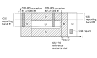
- FIG. 16 is a diagram for explaining operation example 1.
- operation example 1 the operation of the UE 200, which communicates with a base station using an extended duplex method, regarding CSI measurement and transmission (report) of a CSI report will be described.
- the following optional sequence may be set for the sequence of CSI measurement, CSI report transmission, etc. in operation example 1.
- the UE 200 may perform CSI measurement and CSI reporting without distinguishing between the two types of symbols and/or slots.
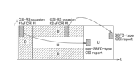
- the UE 200 may distinguish two CSI measurement results in two types of symbols and/or slots and transmit (report) them as one CSI report.
- the UE 200 may perform CSI measurement and CSI reporting without distinguishing between the two types of symbols and/or slots.
- the UE 200 performs at least one of CSI measurement of the SBFD symbol and/or SBFD slot, and CSI measurement of the non-SBFD symbol and/or non-SBFD slot. and the measurement results may be reported as a CSI report without distinction.
- the control unit of the UE 200 may perform CSI measurement in two types of symbols and/or slots.
- the transmitter of the UE 200 may select which measurement results to include in the CSI report without distinguishing between them, and may transmit (report) the selected measurement results by including them in the CSI report.
- a case in which the predetermined condition is not met means that there is a large difference between the interference level in the SBFD symbol and/or SBFD slot (first interference level) and the interference level in the non-SBFD symbol and/or non-SBFD slot (second interference level). It can be interpreted as if there is no.
- the control unit of the UE 200 determines whether the level of the difference between the first interference level and the second interference level exceeds a predetermined value, and if it does not exceed the predetermined value, the control unit controls the first interference level. It may be determined that there is no large difference between the level and the second interference level. In this case, the UE 200 may measure the CSI in the two types of symbols and/or slots without distinguishing between them.
- SBFD symbol and/or SBFD slot may be abbreviated as “SBFD symbol/slot.”
- Non-SBFD symbols and/or non-SBFD slots may be abbreviated as “non-SBFD symbols/slots.”
- the interference level may be measured based on CSI-Interference Measurement (CSI-IM) resources indicated by the network.
- CSI-IM CSI-Interference Measurement
- the interference level may be interpreted as signal strength such as power, or may be interpreted as reception level.
- the predetermined value may be pre-configured in the UE 200, or may be set based on radio parameters notified from the gNB 100.
- Non-SBFD symbols/slots may be interpreted as symbols and/or slots in the DL band in the time T' domain as shown in FIG.
- the UE may set the CSI measurement result of the SBFD symbol/slot in the CSI report.
- the UE 200 may set the CSI measurement result of the non-SBFD symbol/slot in the CSI report.
- the overlap can be avoided by the sequence shown in option 2-1 or option 2-2 in operation example 2, which will be described later.
- the fact that the CSI-RS occurrence overlaps with the SBFD symbol/slot may be interpreted as the CSI-RS occurrence colliding with the SBFD symbol/slot.
- the following option sequence may be set for the CSI-RS occasion selection by the UE 200. may be set.
- CSI-RS occasion selection case 1 If the upper layer parameter (timeRestrictionForChannelMeasurements) is not set in the CSI-ReportConfig, the UE 200 uses the o of the NZP CSI-RS which is not slower than the CSI reference resource. Select only ccasion. The UE 200 may derive channel measurements for calculating the CSI value reported in uplink slot n based on the selected NZP CSI-RS occasion. Furthermore, the UE 200 that has derived the channel measurement value may transmit an actual CSI report using the RB corresponding to the CSI report band associated with the CSI resource setting.
- the upper layer parameter timeRestrictionForChannelMeasurements
- CSI-ReportConfig may be interpreted as information indicating the CSI measurement report method.
- a CSI reference resource may be interpreted as a resource that can be used to measure CSI.
- CSI-RS occasion selection case 2 If the upper layer parameter (timeRestrictionForChannelMeasurements) is set in CSI-ReportConfig, the UE 200 uses the latest NZP CSI-RS (non-zero-power CSI-RS) that is not slower than the CSI reference resource. Select only the occasion of and based on the selected NZP CSI-RS occurrence, channel measurements may be derived for calculating the CSI value reported in uplink slot n. Furthermore, the UE 200 that has derived the channel measurement value may transmit an actual CSI report using the RB corresponding to the CSI report band associated with the CSI resource setting.
- NZP CSI-RS non-zero-power CSI-RS
- the CSI reference resource determination method (CSI reference resource determination) may be different from the CSI reference resource determination rule in Release 15 of 3GPP.
- - Frequency domain Similar to Release 15, indicates the RB corresponding to the CSI report band set in "CSI-ReportingBand”.
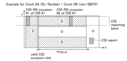
- ⁇ Time domain Valid CSI occasion slot [n' ⁇ 2 ⁇ DL /2 ⁇ UL ]-n CSI, ref The above n CSI,ref , ⁇ DL, and ⁇ UL are defined in Release 15.
- a CSI occasion slot that satisfies any of the conditions (Cond) shown below can be regarded as a valid CSI occasion slot.
- Cond-2A Cond-2A
- Cond-2B Cond-2C
- Cond-2C any one of Cond-2A, Cond-2B, and Cond-2C shown below, or any combination thereof may be used.
- Cond-2A Be configured with at least one upper layer configuration (DL/flexible symbol). Note that the combination of Cond-1 and Cond-2A (Cond-1+Cond-2A) is also a condition of Release 15 of 3GPP.
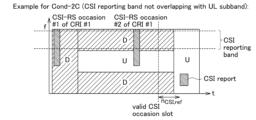
- Cond-2C 18 and 19 are diagrams for explaining Cond-2C in operation example 1.
- Each RB corresponding to the CSI report band has at least one symbol configured as DL, that is, a symbol whose frequency domain for deriving the CSI on the symbol (CSI report band) does not overlap with the UL subband (see FIG. 18). and is configured.
- FIG. 19 shows an example in which each RB corresponding to a CSI report band is configured of symbols in which the frequency domain for deriving the CSI report band on the symbol overlaps with the UL subband.
- FIG. 17 is a diagram for explaining the combination of Cond-2A and Cond-2B in operation example 1. Consists of at least one higher layer configured DL/flexible symbol that is configured (or not configured) for SBFD operation. - If Cond-1 is already satisfied, if the slot contains one DL/flexible symbol, it can become a CSI reference resource slot based on 3GPP Release 15 rules. - However, in the combination of Cond-2A and Cond-2B, even if the slot includes the DL/flexible symbol, if the DL/flexible slot is set to SBFD operation (or not set), the CSI reference will be made. It does not become a slot for resources.
- Each RB corresponding to a CSI report band has at least one DL/flexible layer configured such that the frequency domain (CSI report band) for deriving CSI on a symbol does not overlap with the UL subband. Consists of symbols. - If Cond-1 is already satisfied, if the slot contains one DL/flexible symbol, it can become a CSI reference resource slot based on 3GPP Release 15 rules. - However, in the combination of Cond-2A and Cond-2C, even if the slot includes a DL/Flexible symbol, if it is set to SBFD and the CSI report band and UL subband overlap, the CSI reference resource slot.
- Each RB consisting of at least an SBFD (or non-SBFD) symbol and corresponding to a CSI report band on that symbol is configured such that the frequency domain from which DL, i.e. CSI, is derived (CSI report band) does not overlap with the UL subband. is being done.
- the UE 200 may distinguish two CSI measurement results in two types of symbols and/or slots and transmit (report) them as one CSI report.
- the case where the predetermined condition is satisfied can be interpreted as a case where there is a large difference between the interference level in the SBFD symbol/slot (first interference level) and the interference level in the non-SBFD symbol/slot (second interference level). .
- the control unit of the UE 200 determines whether the level of the difference between the first interference level and the second interference level exceeds a predetermined value, and if it exceeds the predetermined value, the control unit controls the first interference level. It may be determined that there is a large difference between the level and the second interference level.
- the UE 200 may report the CSI measurement results using option 2-1 and option 2-2 below.
- the UE 200 performs at least one of CSI measurement of SBFD symbols/slots and CSI measurement of non-SBFD symbols/slots, distinguishes the measurement results, and then displays only one of the measurement results. may be included in one CSI report and transmitted (reported).
- CRI CSI-RS Resource Index
- CMR may be interpreted as a resource used for channel measurements.
- Option 2 Measurement result reporting format case 2
- the UE 200 may report measurement results using D symbols based on gNB guidance or settings defined in the specifications.
- the gNB 100 may explicitly or implicitly instruct whether to measure CSI in non-SBFD symbols/slots or in SBFD symbols/slots for CSI reporting.
- the gNB 100 specifies that the CSI report is based on measurements in non-SBFD symbols/slots or SBFD symbols/slots by specifying a new RRC parameter (e.g., CSI-report-SBFD) or a new one in the RRC configuration, e.g., CSI-ReportConfig.
- the UE 200 may be notified using report quantity candidate values.
- the gNB 100 may also indicate to the UE 200 that there are new parameters in the associated trigger state configuration.
- the report amount candidate values include "cri-RI-PMI-CQI-SBFD”, “cri-RI-i1-SBFD”, “cri-RI-i1-CQI-SBFD”, “cri-RSRP-SBFD", " Examples include "cri-SINR-SBFD” and "cri-RI-LI-PMI-CQI-SBFD.”
- the gNB 100 instructs the UE 200 by activation DCI or MAC CE that the CSI report is based on measurements in non-SBFD symbols/slots, or that it is based on measurements in SBFD symbols/slots. good.
- gNB 100 configures CSI-RS resources such that each CSI-RS occurrence does not overlap with SBFD symbols/slots for CSI reporting, UE 200 generates CSI reports based on measurements in non-SBFD symbols/slots. You can go.
- the gNB 100 configures CSI-RS resources such that each CSI-RS occurrence overlaps with the SBFD symbols/slots for CSI reporting, the UE 200 performs CSI reporting based on measurements in the SBFD symbols/slots. It's fine.
- the CSI measurements may be defined as being set on non-SBFD symbols/slots (or SBFD symbols/slots if the CSI-RS occurrence of the associated CSI-RS resource overlaps with the SBFD symbol).
- Option 2-1A and Option 2-1B the following option sequences may be set.
- CSI-RS occasion selection case 1-1 If the upper layer parameter (timeRestrictionForChannelMeasurements) is not set in the CSI-ReportConfig, the UE 200 uses the CSI reference resource that is not slower than the CSI reference resource that overlaps with the SBFD symbol/slot. Select only the P CSI-RS occasion do. The UE 200 may derive channel measurements for calculating the CSI value reported in uplink slot n based on the selected NZP CSI-RS occasion.
- timeRestrictionForChannelMeasurements is not set in the CSI-ReportConfig.
- the UE 200 that has derived the channel measurement value may transmit an actual CSI report using the RB corresponding to the CSI report band associated with the CSI resource setting.
- CSI-RS occasion selection case 1-2 If the upper layer parameter (timeRestrictionForChannelMeasurements) is set in the CSI-ReportConfig, the UE 200 uses the latest NZP CSI-RS (non-zero-po was CSI- RS). UE 200 may derive channel measurements for calculating the CSI value reported in uplink slot n based on the selected NZP CSI-RS occasion.
- the UE 200 that has derived the channel measurement value may transmit an actual CSI report using the RB corresponding to the CSI report band associated with the CSI resource setting.
- the CSI reference resource determination may reuse the CSI reference resource determination rule in Release 15 of 3GPP, or may be different from the CSI reference resource determination rule. .
- CSI reference resource determination (CSI reference resource determination method) described in Option 1 of Operation Example 1 is applicable to Case 1-1 and the sequence of Case 1-1.
- possible combinations with option 1 include "Cond-1+Cond-2B (SBFD required)" and "Cond-1+Cond-2B (SBFD required)+Cond-2C.”
- CSI-RS occasion selection case 2-1 If the upper layer parameter (timeRestrictionForChannelMeasurements) is not set in the CSI-ReportConfig, the UE 200 uses a CSI reference resource that is not slower than the CSI reference resource that does not overlap with the SBFD symbol/slot. Select only the P CSI-RS occasion do. The UE 200 may derive channel measurements for calculating the CSI value reported in uplink slot n based on the selected NZP CSI-RS occasion.
- timeRestrictionForChannelMeasurements is not set in the CSI-ReportConfig.
- the UE 200 that has derived the channel measurement value may transmit an actual CSI report using the RB corresponding to the CSI report band associated with the CSI resource setting.
- CSI-RS occasion selection case 2-2 If the upper layer parameter (timeRestrictionForChannelMeasurements) is set in CSI-ReportConfig, the UE 200 uses the latest NZP CSI-RS (non-zero-po was CSI- RS). UE 200 may derive channel measurements for calculating the CSI value reported in uplink slot n based on the selected NZP CSI-RS occasion.
- the UE 200 that has derived the channel measurement value may transmit an actual CSI report using the RB corresponding to the CSI report band associated with the CSI resource setting.
- the CSI reference resource determination may reuse the CSI reference resource determination rule in Release 15 of 3GPP, or may be different from the CSI reference resource determination rule. .
- CSI reference resource determination (CSI reference resource determination method) described in Option 1 of Operation Example 1 is applicable to Case 2-1 and the sequence of Case 2-1.
- Cond-1+Cond-2B non SBFD required
- the UE 200 transmits (reports) each of the CSI measurement results of SBFD symbols/slots and the CSI measurement results of non-SBFD symbols/slots in one CSI reporting instance (CSI reporting instance). ) may be done.
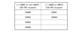
- Option 2-2 Sequence 1 Specifically, the UE 200 uses a maximum of N strongest beams (CRI) measured in a "non-SBFD CSI-RS occasion" and a maximum of M strongest beams measured in a "SBFD CSI-RS occasion". (CRI) may be reported.
- Option 2-2 Sequence 2 The UE 200 may apply the same sequence as Option 2-1A and Option 2-1B in Operation Example 1 described above for each type of measurement result.
- FIG. 22 In the case of the CMR configuration of CRI #1, the UE 200 may report measurement results in one CSI report instance in CSI-RSoccasion #1 and CSI-RSoccasion #2.
- Example 2 As shown in FIG. 23, in the case of the CMR configuration of CRI #1 and CRI #2, the UE 200 may report the measurement results of the "D" symbol and the "SBFD" symbol in one CSI report instance.
- FIG. 24 shows an example of report contents reported to the gNB 100 according to the sequence of option 2-2.
- the index (CRI) for managing the beam may be reported in association with each of the non-SBFD reception quality (SINR) and the SBFD reception quality (SINR).
- the rule for determining the CRI takes into account the CLI measurement result (CLI value). good.
- the UE 200 may report the N strongest beams after excluding the M beams with the strongest CLI values (e.g., the beams in the L1-RSRP/L1-SINR/CQI/PMI/RI/LI CSI report). (if L1/L2/L3 CLI measurements are configured/activated).
- the M beams with the strongest CLI values e.g., the beams in the L1-RSRP/L1-SINR/CQI/PMI/RI/LI CSI report. (if L1/L2/L3 CLI measurements are configured/activated).
- the UE 200 may report the strongest N beams after excluding beams with CLI values greater than a threshold (e.g., for beams in L1-RSRP/L1-SINR/CQI/PMI/RI/LI CSI report).
- a threshold e.g., for beams in L1-RSRP/L1-SINR/CQI/PMI/RI/LI CSI report.
- the UE 200 may report the strongest N beams among the M beams with the lowest CLI value (L1/RSRP/L1-SINR/CQI/PMI/RI/LI for the beam in the CSI report). If L2/L3 CLI measurements are configured/activated, the relationship between M and N is M>N).
- the UE 200 may report the strongest N beam and the corresponding CLI (L1/L2/L3 CLI measurements configured/for the beam in the L1-RSRP/L1-SINR/CQI/PMI/RI/LI CSI report). if enabled).
- the UE 200 may perform CSI measurement and CSI report without distinguishing between two types of symbols and/or slots. Further, if a predetermined condition is satisfied, the UE 200 may distinguish two CSI measurement results in two types of symbols and/or slots and transmit (report) them as one CSI report. As a result, according to operation example 1, when the respective interference levels of a non-SBFD symbol and an SBFD symbol are approximately equal, instead of reporting a CSI report for both of these symbols, a CSI report is performed for one of the symbols. , the processing load on the UE 200 can be reduced, and UL time and frequency resources can be effectively utilized.
- FIG. 25, FIG. 26, and FIG. 27 are diagrams for explaining operation example 2.
- the UE 200 which communicates with a base station using an extended duplex method, measures the channel state when allowing duplication of resources for DL reference signals in the UL band at a specified time or within a specified time.
- An example will be described in which the related operations and the operations related to channel state measurement in the case where the duplication is not allowed are controlled.
- the UE 200 determines "any/each CSI-RS occasion to overlap with" the CSI-RS resource in the CSI-RS resource set (CSI-RS resource set). UL sub-band in SBFD symbol” or “overlap with UL sub-band in SBFD symbol”.
- the CSI-RS resource set is configured with “repetition ON/OFF”.
- a CSI-RS resource has a certain report quantity.
- specific reporting volumes include: "'none', 'cri-RI-PMI-CQI', 'cri-RI-i1', 'cri-RI-i1-CQI', 'cri-RI-CQI', 'cri-RSRP', 'ssb- Index-RSRP', 'cri-SINR', 'ssb-Index-SINR', 'cri-RI-LI-PMI-CQI'
- a CSI-RS resource is associated with a CSI resource configuration configured with a specific resource type.
- specific resource types include: "'periodic', 'semipersistent', and/or 'periodic'"
- a CSI-RS resource is associated with a CSI report configured with a specific report type.
- specific report types include: "'periodic', 'semipersistent', and/or 'periodic'"
- a CSI-RS resource is associated with a CSI report configured with a particular report band configuration.
- report band configurations include the following: "'widebandCQI', 'subbandCQI', 'widebandPMI', and/or 'subbandPMI'"
- the sequence of the UE 200 may be set as follows.
- the UE 200 recognizes that the CSI-RS has collided with the SBFD symbol (see FIG. 26). Specifically, the UE assumes that the CSI-RS occasion is mapped to a non-SBFD symbol or to a RE/RB that is not a UL subband. That is, the UE 200 assumes that some of the RE/RBs of the CSI-RS resource are retained and some of the RE/RBs of the CSI-RS resource are not transmitted.
- the UE 200 recognizes that the CSI-RS has been postponed to the next resource (see FIG. 27).
- the UE 200 may recognize that the CSI-RS has been postponed to the next resource or later. Specifically, it is assumed that the UE 200 postpones or delays the CSI-RS occurrence to the next slot until the CSI-RS occurrence in the postponed or delayed slot no longer overlaps with the SBFD symbol.
- Option example 2 Application conditions for option 2
- the UE 200 can apply option 2-1, option 2-2, and option 2-3 of operation example 2 if at least one of the conditions (Cond) shown below is satisfied.
- the CSI-RS resource set is configured with “repetition ON/OFF”.
- a CSI-RS resource has a certain report quantity.
- specific reporting volumes include: "'none', 'cri-RI-PMI-CQI', 'cri-RI-i1', 'cri-RI-i1-CQI', 'cri-RI-CQI', 'cri-RSRP', 'ssb- 'Index-RSRP', 'cri-SINR', 'ssb-Index-SINR', and/or 'cri-RI-LI-PMI-CQI'
- a CSI-RS resource is associated with a CSI resource configuration configured with a specific resource type.
- specific resource types include: "'periodic', 'semipersistent', and/or 'periodic'"
- a CSI-RS resource is associated with a CSI report configured with a specific report type.
- specific report types include: "'periodic', 'semipersistent', and/or 'periodic'"
- a CSI-RS resource is associated with a CSI report configured with a particular report band configuration.
- report band configurations include the following: "'widebandCQI', 'subbandCQI', 'widebandPMI', 'subbandPMI'"
- the following conditions (Cond) are met: If at least one of the conditions is satisfied, there is a concern that the above-mentioned adverse effects will occur.
- Conditions that may have an adverse effect will be described.
- the UE performs an operation related to measuring the channel state in a case where duplication of resources for DL reference signals is allowed in the UL band at a specified time or within a specified time. and operations related to channel state measurement in the case where the duplication is not allowed.
- the UE 200 can change the operation related to channel state measurement depending on whether the resources for DL reference signals overlap or not. Therefore, for example, if duplication is not allowed, it is possible to reduce the negative impact on the resources for DL reference signals (CSI-RS occasion, etc.), and it is possible to suppress the deterioration of communication quality in the expanded duplex method. .
- CSI measurement and CSI reporting can be appropriately executed in communication using the extended duplex method.
- Enhancement #1 Make it possible to set discontinuous RBs.
- Enhancement #2 Enabling narrowband RB settings.
- Enhancement #3 Enable the setting of divided CSI-RS.
- Enhancement #4 Enable the setting of divided frequency resources.
- Enhancement #5 Specify different interpretations depending on whether it is SBFD or not.
- Enhancement #1 to #5 Specific examples of Enhancements #1 to #5 will be described below.
- FIG. 30 is a diagram illustrating an example of subband settings in Enhancement #1 (Example 1) of Operation Example 3.
- the gNB 100 may configure up to X non-contiguous subbands in the CSI-RS resource. Specifically, as shown in FIG. 30, a plurality of DL subbands may be set to sandwich a UL subband. This subband means a set of consecutive RBs.
- X may be a fixed value defined in the specification or a value dependent on the SBFD subband configuration. Specifically, X may be a value no greater than the maximum number of DL subbands in an SBFD symbol/slot.
- the size of one subband may be an integral multiple of N (N: a natural number greater than or equal to 1) RBs.
- N a natural number greater than or equal to 1
- the size of one subband may be 2/4/8/16 RBs.
- FIG. 28 is a diagram illustrating a configuration example of subband information elements in Enhancement #1 (Example 1) of Operation Example 3.
- Example 2 When a frequency subband bitmap is configured for the CSI-RS resource, and each bit indicates whether Y (Y: a natural number of 1 or more) RB groups are allocated to the CSI-RS resource.
- the RB group may include all RBs of the BWP (i.e., from the first RB of the BWP to the last RB of the BWP) or may include configurable PRBs (e.g., determined by the upper layer parameters nrofRBs and startRB of the CSI-RS). physical resource blocks).
- FIG. 29 is a diagram illustrating a configuration example of subband information elements in Enhancement #1 (Example 2) of Operation Example 3.
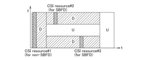
- the gNB 100 may narrow band allocation of RBs for CSI-RS.
- the number of RBs may be set to a value smaller than 24.
- the gNB 100 may configure separate CSI-RS resources (or resource sets/configurations) for SBFD symbols/slots and non-SBFD symbols/slots.
- FIG. 31 is a diagram illustrating a setting example of CSI-RS resources in Enhancement #3 (option 1, example 1) of operation example 3.
- the gNB 100 may configure the CSI-RS resource (or CSI-RS resource set/configuration) of the SBFD so that the CSI-RS occurrence does not overlap with the UL subband.
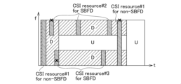
- FIG. 32 is a diagram illustrating a setting example of CSI-RS resources in Enhancement #3 (option 1, example 2) of operation example 3.
- the gNB 100 configures the Explicit RRC parameter to indicate whether the CSI-RS resource (or CSI-RS resource set/configuration) is for SBFD symbols/slots or non-SBFD symbols/slots. It's fine.
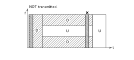
- Example 2-1 As shown in FIG. 32, if the CSI-RS resource (or CSI-RS resource set/configuration) configured for SBFD has a CSI-RS occurrence that does not overlap with an SBFD symbol/slot, the CSI-RS resource is not transmitted. It may be sent, or it may not be sent.
- Example 2-2 As shown in FIG. 32, if the CSI-RS occasion of the CSI-RS resource (or CSI-RS resource set/configuration) configured for non-SBFD overlaps with the SBFD symbol/slot, the CSI-RS resource is It may or may not be transmitted.
- Enhancement #3 (Enhancement #3: Option 2)
- the sequence of Enhancement #3 can also be linked with the sequence of option 2-1 of operation example 1.
- the gNB 100 may implicitly consider a CSI report related to a CSI resource (or resource set/setting) configured exclusively for SBFD (or non-SBFD) as a CSI report for measurement results in SBFD (or non-SBFD). .
- Example 2 of option 2 For a CSI report that is specified as a report of measurement results in SBFD (or non-SBFD), the UE 200 must ensure that the CSI-RS resource (or resource set/configuration) is configured exclusively for SBFD (or non-SBFD). may be assumed.
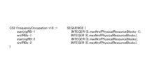
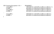
- (Enhancement #4) 33 and 34 are diagrams illustrating configuration examples of information elements of frequency band configuration in Enhancement #4 of operation example 3.
- the gNB 100 may set different frequency band configurations (for example, different startPRBs and/or nrofPrbs) in the CSI-RS resource for cases where the CSI-RS occurrence overlaps with the SBFD symbol and cases where the CSI-RS occurrence does not overlap.
- ⁇ starting PRB1, #PRB1 ⁇ is selected, and if the CSI-RS resource overlaps with the SBFD symbol, ⁇ starting PRB2, #PRB2 ⁇ is selected. ⁇ is selected (see FIG. 33).
- FIG. 35 is a diagram for explaining an operation example in Enhancement #5 of operation example 3.
- Enhancement #4 when the CSI-RS resource overlaps with the SBFD symbol and when it does not overlap, the UE performs the following regarding each frequency band configuration (for example: difference in startPRB and/or nrofPrbs). different interpretations may apply.
- the UE 200 may perform CSI measurement and CSI reporting by inheriting the interpretation in the frequency band configuration of 3GPP Release 15, Release 16, and/or Release/17. .
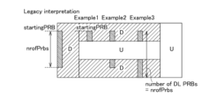
- Example 1 of FIG. 35 the UE 200 may assume that the CSI-RS frequency band is within the DL subband. That is, the UE 200 may assume that the number of PRBs is determined by the configured nrofPrbs and the DL subband size.
- Example 2 of FIG. 35 the UE 200 assumes that the CSI-RS frequency band spans discontinuous DL subbands and that the offset from the starting PRB (that is, startingPRB) to the ending PRB is equal to nrofPrbs. good.
- the UE 200 may assume that the number of PRBs is equal to nrofPrbs and that the CSI-RS frequency band can span non-contiguous DL subbands. If the number of DL PRBs from the starting PRB (i.e., startingPRB) to the last PRB of the BWP is less than nrofPrbs, then the RBs assigned to the CSI-RS occasion are all from the starting PRB (i.e., startingPRB) to the last PRB of the BWP. This is the DL PRB.
- the gNB 100 prevents duplication of resources for DL reference signals within the specified time T or duplication of resources for DL reference signals in the UL band within the specified time T. To avoid this, the resource configuration of DL reference signals can be adjusted. This makes it possible to further reduce the negative impact on DL reference signal resources (CSI-RS occasion, etc.) in communications that apply the extended duplex method, and to reliably suppress deterioration in communication quality. .
- FIG. 36 is a diagram for explaining problems related to operation example 4.
- the gNB100 configures wideband CSI-RS resources and narrowband CSI-RS resources separately, and when covering the wideband CSI report band, the following problems may occur. can occur. That is, based on current limitations (e.g., same frequency band allocation of CSI-RS resources in one resource set), in order to report CSI measurements covering a wide reporting band, three CSI resource sets are required.
- RRC configuration overhead may occur in the CSI resource sets/settings/reporting configuration
- CSI report overhead may also occur in the CSI report.
- a maximum of X (X: a natural number greater than or equal to 1) CSI-RS resource sets may be regarded as one associated "valid CSI-RS resource set.”
- a maximum of X (X: a natural number greater than or equal to 1) CSI-RS resource configurations may be regarded as one associated "valid resource configuration.”
- (Alt2 details) 37 and 38 are diagrams for explaining the Alt2 sequence of operation example 4.
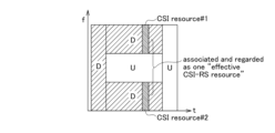
- the gNB 100 and/or the UE 200 may consider a maximum of X CSI-RS resources having different frequency bands as one associated "valid CSI-RS.” X can be defined in the specifications.
- the related CSI-RS resource shall have the elements shown below.
- Same time domain behavior e.g. periodic, aperiodic, semi-permanent.
- Same symbol allocation e.g. firstOFDMSymbolInTimeDomain and firstOFDMSymbolInTimeDomain2.
- ⁇ Same CDM (code division multiplex) type ⁇ Same CSI-RS transmission density ⁇ Same nrofPorts - Same RE allocation within RB (frequency Domain Allocation).
- the UE 200 can use up to X CSI-RS resources with different frequency bands, as shown in FIG.
- An RS resource may be considered as one "valid CSI-RS" associated with it.
- the CSI report provides one measurement result for the related CSI-RS resource. Also, any/minimum/maximum CRI associated with the CSI-RS resource may be reported.
- One measurement result obtained for the associated CSI-RS resources can be based on: (Alt1) The signals on the related CSI-RS resources are treated as one signal, and therefore the obtained measurement value is also one. (Alt2) The average value/maximum value/minimum value/filtering value of the measurement results obtained for each related CSI-RS resource is determined as the result of the related CSI-RS resource.
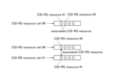
- CSI-RS resource sets different frequency band configurations are set for the CSI-RS resources. There are the same number of CSI-RS resources for each associated CSI-RS resource set, and CSI-RS resources in different resource sets have a one-to-one mapping relationship. Mapped CSI-RS resources in different CSI-RS resource sets can be considered as one "valid CSI-RS resource.”
- FIG. 39 is a diagram for explaining the Alt3 sequence of operation example 4.
- CSI-RS resource set #0 and CSI-RS resource set #1 are associated, the two CSI-RS resource sets are combined into one CSI configuration for CSI reporting. or one trigger condition.
- the UE 200 can acquire related CSI-RS resources based on the "effective CSI-RS resource set" of the related CSI resource set. For CSI reports, one measurement result is obtained for the associated CSI-RS resource.
- the conditions of the related CSI-RS resource set can be reused.
- Different frequency band configurations are set for CSI-RS resources in different CSI-RS resource sets.
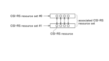
- the CSI-RS resources in different resource sets have a one-to-one mapping relationship, and the mapped CSI-RS resources in different resource sets are , is regarded as one "valid CSI-RS resource”.
- FIG. 40 is a diagram for explaining the Alt4 sequence of operation example 4.
- two CSI-RS resource sets are combined into one CSI-RS resource set for CSI reporting. It can be associated with a setting or associated with one trigger condition.
- the UE 200 can acquire related CSI-RS resources based on the "effective CSI-RS resource set" of the related CSI resource set. For CSI reports, one measurement result is obtained for the associated CSI-RS resource. Any/minimum/maximum CRI associated with the CSI-RS resource may be reported.
- gNB 100 and/or UE 200 can reduce the overhead of DL signaling or UL signaling in communication applying the extended duplex method, so In addition to the effects, UL or DL data resources can be effectively utilized.
- each option (1, 2) in the above-mentioned operation example 1 corresponds to a different CSI report amount (for example, L1-RSRP, L1-SINR, CQI, PMI, RI, LI) and a different time domain operation (for example, periodic CSI reporting) or on different physical channels (e.g. PUCCH/PUSCH).
- a different CSI report amount for example, L1-RSRP, L1-SINR, CQI, PMI, RI, LI
- a different time domain operation for example, periodic CSI reporting
- PUCCH/PUSCH physical channels
- CSI Type consistency must be maintained for each CRI associated with a report.
- Any option of Operation Example 1 can be combined with any option of Operation Examples 2 to 4. Furthermore, any of the options in operation examples 2 to 4 can be combined with each other.
- the UE capability may be defined as to whether the UE 200 supports non-contiguous RB allocation of CSI-RS resources.
- the UE capability may also be defined as to whether the UE 200 supports different frequency band configurations (ie, different starting PRBs and numbers of RBs) for CSI-RS resources within the same CSI-RS resource set.
- the UE capability is defined as to whether the UE 200 supports considering multiple related CSI-RS resources (or resource sets, resource configurations) as one "valid CSI-RS resource (set/configuration)". good.
- UE capability may be defined regarding whether the UE 200 supports separate CSI-RS resource (set/configuration) configurations for SBFD and non-SBFD.
- the UE capability may be defined regarding whether the UE 200 supports allocation of individual frequency bands for CSI-RS resource configuration for each of SBFD and non-SBFD.
- the UE capability may be defined regarding whether the UE 200 supports interpretation of different frequency bands for CSI-RS resource configurations in SBFD and non-SBFD.
- the UE capability may be defined regarding whether the UE 200 supports CSI-RS occasions that overlap with the UL subband of the SBFD symbol/slot.
- UE capability may be defined regarding whether the UE 200 supports CSI-RS occasions that overlap with SBFD symbols/slots.
- UE capability may be defined as to whether the UE 200 supports individual CSI report settings for each of SBFD and non-SBFD.
- the UE according to the embodiment of the present disclosure is configured with a base station that performs communication in a manner in which DL bands and UL bands are allocated in a non-overlapping manner in the frequency direction within a specified time based on time division duplexing.
- a receiving unit that receives the DL reference signal, an operation related to measuring a channel state in a case where duplication of resources for the DL reference signal in the UL band at or within the specified time is allowed; and a control unit that controls operations related to channel state measurement when duplication is not permitted.
- the DL reference signal includes a channel state information reference signal (CSI-RS), and the control unit of the UE 200 assigns a subband non-overlapping full duplex (SBFD) symbol or a resource for the CSI-RS to the SBFD slot. Controls operations related to the measurement of the channel state when duplication is not allowed or when duplication of the CSI-RS resource in the UL band in the SBFD symbol is not allowed.
- CSI-RS channel state information reference signal
- SBFD subband non-overlapping full duplex
- CSI measurement and/or CSI report transmission may be interrupted. Measures can be taken. Therefore, the processing load on the UE 200 due to CSI measurement etc. is reduced, and the UL time and frequency resources based on the CSI report can be effectively utilized.
- the DL reference signal includes a channel state information reference signal (CSI-RS), and the control unit of the UE 200 assigns a subband non-overlapping full duplex (SBFD) symbol or a resource for the CSI-RS to the SBFD slot. Controls operations related to the measurement of the channel state when duplication is permitted or when duplication of the CSI-RS resource in the UL band in the SBFD symbol is permitted.
- CSI-RS channel state information reference signal
- SBFD subband non-overlapping full duplex
- a plurality of resource blocks used for measuring channel state information are set non-contiguously. This increases the possibility of avoiding duplication of CSI-RS occasions compared to the case where multiple resource blocks used for measuring channel state information are configured consecutively, and improves communication quality in the extended duplex method. Deterioration can be suppressed.
- resource blocks used for measuring channel state information are set, and the number of resource blocks is set to a value smaller than a predetermined value. This increases the possibility of avoiding duplication of CSI-RS occasions compared to the case where the number of multiple resource blocks used to measure channel state information is greater than a predetermined value, and improves communication quality in the expanded duplex method. Deterioration can be suppressed.
- the resources for the DL reference signal are allocated respectively to the specified time and a time domain outside the specified time, or respectively allocated to a DL band within the specified time and a DL band in a time domain outside the specified time. is assigned to. This makes it possible to measure the communication quality in each area by using the CSI-RS resources set in each of the area within the specified time and the area outside the specified time. Therefore, even when communicating using the extended duplex method, the DL channel states of non-SBFD and SBFD can be measured with high accuracy.
- the words “configure”, “activate”, “update”, “indicate”, “enable”, “specify”, and “select” can be read interchangeably. good.
- the words “link”, “associate”, “correspond” and “map” may be used interchangeably, and “allocate”, “assign”, and “monitor” may be used interchangeably.
- map may also be read interchangeably.
- precoding "precoding weight”
- QCL quadsi-co-location
- TCI state "Transmission Configuration Indication state
- space space
- spatial relation "spatial domain filter”
- transmission power "phase rotation”
- antenna port "antenna port group”
- layer "number of layers”
- Terms such as “rank”, “resource”, “resource set”, “resource group”, “beam”, “beam width”, “beam angle”, “antenna”, “antenna element”, and “panel” are interchangeable.
- each functional block may be realized using one physically or logically coupled device, or may be realized using two or more physically or logically separated devices directly or indirectly (e.g. , wired, wireless, etc.) and may be realized using a plurality of these devices.
- the functional block may be realized by combining software with the one device or the plurality of devices.
- Functions include judgment, decision, judgment, calculation, calculation, processing, derivation, investigation, exploration, confirmation, reception, transmission, output, access, resolution, selection, selection, establishment, comparison, assumption, expectation, consideration, broadcasting, notifying, communicating, forwarding, configuring, reconfiguring, allocating, mapping, allocation gning), but these are limited to I can't do it.
- a functional block (configuration unit) that performs transmission is called a transmitting unit or a transmitter. In either case, as described above, the implementation method is not particularly limited.
- FIG. 41 is a diagram illustrating an example of the hardware configuration of the gNB 100 and the UE 200.
- the device may be configured as a computer device including a processor 1001, a memory 1002, a storage 1003, a communication device 1004, an input device 1005, an output device 1006, a bus 1007, and the like.
- the word “apparatus” can be read as a circuit, a device, a unit, etc.
- the hardware configuration of the device may include one or more of the devices shown in the figure, or may not include some of the devices.
- Each functional block of the device (see FIG. 4) is realized by any hardware element of the computer device or a combination of hardware elements.
- each function in the device is performed by loading predetermined software (programs) onto hardware such as the processor 1001 and memory 1002, so that the processor 1001 performs calculations, controls communication by the communication device 1004, and controls the memory This is realized by controlling at least one of reading and writing data in the storage 1002 and the storage 1003.
- predetermined software programs
- the processor 1001 for example, operates an operating system to control the entire computer.
- the processor 1001 may be configured by a central processing unit (CPU) that includes interfaces with peripheral devices, a control device, an arithmetic unit, registers, and the like.
- CPU central processing unit
- the processor 1001 reads programs (program codes), software modules, data, etc. from at least one of the storage 1003 and the communication device 1004 to the memory 1002, and executes various processes in accordance with these.
- programs program codes
- software modules software modules
- data etc.
- the various processes described above may be executed by one processor 1001, or may be executed by two or more processors 1001 simultaneously or sequentially.
- Processor 1001 may be implemented by one or more chips. Note that the program may be transmitted from a network via a telecommunications line.
- the memory 1002 is a computer-readable recording medium, for example, Read Only Memory (ROM), Erasable Programmable ROM (EPROM), Electrically Erasable Programmable RO. Consisting of at least one of M (EEPROM), Random Access Memory (RAM), etc. may be done.
- Memory 1002 may be called a register, cache, main memory, or the like.
- the memory 1002 can store programs (program codes), software modules, etc. that can execute a method according to an embodiment of the present disclosure.
- the storage 1003 is a computer-readable recording medium, such as an optical disk such as a Compact Disc ROM (CD-ROM), a hard disk drive, a flexible disk, a magneto-optical disk (such as a compact disk, a digital versatile disk, or a Blu-ray disk). (registered trademark disk), smart card, flash memory (eg, card, stick, key drive), floppy disk, magnetic strip, etc.
- Storage 1003 may also be called an auxiliary storage device.
- the above-mentioned recording medium may be, for example, a database including at least one of memory 1002 and storage 1003, a server, or other suitable medium.
- the communication device 1004 is hardware (transmission/reception device) for communicating between computers via at least one of a wired network and a wireless network, and is also referred to as a network device, network controller, network card, communication module, etc., for example.
- the communication device 1004 includes, for example, a high frequency switch, a duplexer, a filter, a frequency synthesizer, etc. in order to realize at least one of frequency division duplexing (Frequency Division Duplex: FDD) and time division duplexing (Time Division Duplex: TDD). It may be composed of.
- FDD Frequency Division Duplex
- TDD Time Division Duplex
- the input device 1005 is an input device (eg, keyboard, mouse, microphone, switch, button, sensor, etc.) that accepts input from the outside.
- the output device 1006 is an output device (for example, a display, a speaker, an LED lamp, etc.) that performs output to the outside. Note that the input device 1005 and the output device 1006 may have an integrated configuration (for example, a touch panel).
- each device such as the processor 1001 and the memory 1002 is connected by a bus 1007 for communicating information.
- the bus 1007 may be configured using a single bus, or may be configured using different buses for each device.
- the device includes a microprocessor, a digital signal processor (DSP), an application specific integrated circuit (ASIC), a programmable logic Consists of hardware such as Device (PLD), Field Programmable Gate Array (FPGA), etc.
- DSP digital signal processor
- ASIC application specific integrated circuit
- PLD programmable logic Consists of hardware
- PLD Device
- FPGA Field Programmable Gate Array
- processor 1001 may be implemented using at least one of these hardwares.
- information notification is not limited to the aspects/embodiments described in this disclosure, and may be performed using other methods.
- information notification may be performed using physical layer signaling (e.g., Downlink Control Information (DCI), Uplink Control Information (UCI), upper layer signaling (e.g., RRC signaling, Medium Access Control (MAC) signaling, broadcast information (Master Information Block) (MIB), System Information Block (SIB)), other signals, or a combination thereof.
- DCI Downlink Control Information
- UCI Uplink Control Information
- RRC signaling e.g., RRC signaling, Medium Access Control (MAC) signaling, broadcast information (Master Information Block) (MIB), System Information Block (SIB)
- RRC signaling may also be called an RRC message, for example, RRC Connection Setup (RRC Connection Setup). ) message, RRC Connection Reconfiguration message, etc.
- LTE Long Term Evolution
- LTE-A Long Term Evolution-Advanced
- SUPER 3G IMT-Advanced
- 4th generation mobile communication 4G
- 5th generation mobile communication system 5G
- Future Radio Access (FRA) New Radio
- NR New Radio
- W-CDMA registered trademark
- GSM registered trademark
- UMB Ultra Mobile Broadband
- IEEE 802.11 Wi-Fi (registered trademark)
- IEEE 802.16 WiMAX (registered trademark)
- IEEE 802.20 Ultra-WideBand (UWB), Bluetooth (registered trademark), and other appropriate systems and systems that are extended based on these.
- It may be applied to at least one next generation system.
- a combination of a plurality of systems may be applied (for example, a combination of at least one of LTE and LTE-A and 5G).
- the specific operation performed by the gNB 100 may be performed by its upper node in some cases.
- various operations performed for communication with UE 200 are performed by gNB 100 and other network nodes other than gNB 100 (for example, MME or S-GW). It is clear that this can be carried out by at least one of the following methods (conceivable, but not limited to).
- MME Mobility Management Entity
- S-GW Serving Mobility Management Entity
- Information, signals can be output from an upper layer (or lower layer) to a lower layer (or upper layer). It may be input/output via multiple network nodes.
- the input/output information may be stored in a specific location (for example, memory) or may be managed using a management table. Information that is input and output may be overwritten, updated, or additionally written. The output information may be deleted. The input information may be sent to other devices.
- the determination may be made using a value expressed by 1 bit (0 or 1), a truth value (Boolean: true or false), or a comparison of numerical values (for example, a predetermined value). (comparison with a value).
- notification of prescribed information is not limited to being done explicitly, but may also be done implicitly (for example, not notifying the prescribed information). Good too.
- Software includes instructions, instruction sets, code, code segments, program code, programs, subprograms, software modules, whether referred to as software, firmware, middleware, microcode, hardware description language, or by any other name. , should be broadly construed to mean an application, software application, software package, routine, subroutine, object, executable, thread of execution, procedure, function, etc.
- software, instructions, information, etc. may be sent and received via a transmission medium.
- a transmission medium For example, if the software uses wired technology (coaxial cable, fiber optic cable, twisted pair, digital subscriber line (DSL), etc.) and/or wireless technology (infrared, microwave, etc.) to When transmitted from a server or other remote source, these wired and/or wireless technologies are included within the definition of transmission medium.
- wired technology coaxial cable, fiber optic cable, twisted pair, digital subscriber line (DSL), etc.
- wireless technology infrared, microwave, etc.
- data, instructions, commands, information, signals, bits, symbols, chips, etc. may refer to voltages, currents, electromagnetic waves, magnetic fields or magnetic particles, light fields or photons, or any of the foregoing. It may also be represented by a combination of
- At least one of the channel and the symbol may be a signal.
- the signal may be a message.
- a component carrier may be called a carrier frequency, a cell, a frequency carrier, or the like.
- system and “network” are used interchangeably.
- radio resources may be indicated by an index.
- BS Base Station
- eNB wireless base station
- eNB fixed station
- gNodeB gNodeB
- Access Points "Transmission Point”, “Receive Point”, “Sending Points (Transmission / Reception Point)", "Sel”, “Sel” “Sector”, “Cell Group”, "
- carrier “component carrier”, etc. may be used interchangeably.
- the gNB 100 is sometimes called a macro cell, a small cell, a femto cell, a pico cell, or the like.
- the gNB 100 can accommodate one or more (for example, three) cells (also called sectors). When the gNB 100 accommodates multiple cells, the entire coverage area of the gNB 100 can be divided into multiple smaller areas, and each smaller area is divided into a base station subsystem (e.g., an indoor small base station (Remote Radio Head: Communication services can also be provided by RRH).
- a base station subsystem e.g., an indoor small base station (Remote Radio Head: Communication services can also be provided by RRH).
- cell refers to part or the entire coverage area of at least one of the gNB 100 and the base station subsystem that provide communication services in this coverage.
- MS mobile station
- UE user equipment
- terminal terminal
- a mobile station is defined by a person skilled in the art as a subscriber station, mobile unit, subscriber unit, wireless unit, remote unit, mobile device, wireless device, wireless communication device, remote device, mobile subscriber station, access terminal, mobile terminal, wireless It may also be referred to as a terminal, remote terminal, handset, user agent, mobile client, client, or some other suitable terminology.
- At least one of the gNB 100 and the mobile station may be called a transmitting device, a receiving device, a communication device, etc.
- at least one of the gNB 100 and the mobile station may be a device mounted on a mobile body, the mobile body itself, or the like.
- the moving object may be a vehicle (for example, a car, an airplane, etc.), an unmanned moving object (for example, a drone, a self-driving car, etc.), or a robot (manned or unmanned). ).
- at least one of the gNB 100 and the mobile station also includes devices that do not necessarily move during communication operations.
- at least one of the gNB 100 and the mobile station may be an Internet of Things (IoT) device such as a sensor.
- IoT Internet of Things
- the gNB 100 in the present disclosure may be read as a mobile station (user terminal, hereinafter the same).
- a configuration in which communication between the gNB 100 and the mobile station is replaced with communication between multiple mobile stations for example, may be called Device-to-Device (D2D), Vehicle-to-Everything (V2X), etc.
- D2D Device-to-Device
- V2X Vehicle-to-Everything
- the mobile station may have the functions that the gNB 100 has.
- words such as "upstream” and "downstream” may be replaced with words corresponding to inter-terminal communication (for example, "side").
- uplink channels, downlink channels, etc. may be replaced with side channels.
- the mobile station in the present disclosure may be read as gNB 100.
- the gNB 100 may have the functions that the mobile station has.
- a radio frame may be composed of one or more frames in the time domain. Each frame or frames in the time domain may be called a subframe.
- a subframe may further be composed of one or more slots in the time domain.
- a subframe may have a fixed time length (eg, 1 ms) that does not depend on numerology.
- the numerology may be a communication parameter applied to at least one of transmission and reception of a certain signal or channel.
- Numerology includes, for example, subcarrier spacing (SCS), bandwidth, symbol length, cyclic prefix length, transmission time interval (TTI), number of symbols per TTI, radio frame configuration, transmission and reception. It may also indicate at least one of a specific filtering process performed by the device in the frequency domain, a specific windowing process performed by the transceiver in the time domain, etc.
- a slot is one or more symbols in the time domain (Orthogonal Frequency Division Multiplexing (OFDM)) symbol, Single Carrier Frequency Division Multiple iple Access (SC-FDMA) symbol, etc.).
- OFDM Orthogonal Frequency Division Multiplexing
- SC-FDMA Single Carrier Frequency Division Multiple iple Access
- a slot may be a unit of time based on numerology.
- a slot may include multiple mini-slots. Each minislot may be made up of one or more symbols in the time domain. Furthermore, a mini-slot may also be called a sub-slot. A minislot may be made up of fewer symbols than a slot.
- PDSCH (or PUSCH) transmitted in time units larger than minislots may be referred to as PDSCH (or PUSCH) mapping type A.
- PDSCH (or PUSCH) transmitted using minislots may be referred to as PDSCH (or PUSCH) mapping type B.
- Radio frames, subframes, slots, minislots, and symbols all represent time units when transmitting signals. Other names may be used for the radio frame, subframe, slot, minislot, and symbol.
- one subframe may be called a transmission time interval (TTI)
- TTI transmission time interval
- multiple consecutive subframes may be called a TTI
- one slot or minislot may be called a TTI.
- at least one of the subframe and TTI may be a subframe (1ms) in existing LTE, a period shorter than 1ms (for example, 1-13 symbols), or a period longer than 1ms. It may be.
- the unit representing the TTI may be called a slot, minislot, etc. instead of a subframe.
- TTI refers to, for example, the minimum time unit for scheduling in wireless communication.
- the gNB 100 performs scheduling to allocate radio resources (frequency bandwidth, transmission power, etc. that can be used by each user terminal) to each user terminal on a TTI basis.
- radio resources frequency bandwidth, transmission power, etc. that can be used by each user terminal
- TTI is not limited to this.
- the TTI may be a transmission time unit of a channel-coded data packet (transport block), a code block, a codeword, etc., or may be a processing unit of scheduling, link adaptation, etc. Note that when a TTI is given, the time interval (for example, the number of symbols) to which transport blocks, code blocks, code words, etc. are actually mapped may be shorter than the TTI.
- one slot or one minislot is called a TTI
- one or more TTIs may be the minimum time unit for scheduling.
- the number of slots (minislot number) that constitutes the minimum time unit of the scheduling may be controlled.
- a TTI having a time length of 1 ms may be called a normal TTI (TTI in LTE Rel. 8-12), normal TTI, long TTI, normal subframe, normal subframe, long subframe, slot, etc.
- TTI TTI in LTE Rel. 8-12
- a TTI that is shorter than a normal TTI may be referred to as an abbreviated TTI, short TTI, partial or fractional TTI, shortened subframe, short subframe, minislot, subslot, slot, etc.
- long TTI for example, normal TTI, subframe, etc.
- short TTI for example, short TTI, etc. It may also be read as a TTI having the above TTI length.
- a resource block is a resource allocation unit in the time domain and frequency domain, and may include one or more continuous subcarriers in the frequency domain.
- the number of subcarriers included in an RB may be the same regardless of the numerology, and may be 12, for example.
- the number of subcarriers included in an RB may be determined based on numerology.
- the time domain of an RB may include one or more symbols and may be one slot, one minislot, one subframe, or one TTI in length.
- One TTI, one subframe, etc. may each be composed of one or more resource blocks.
- one or more RBs include a physical resource block (Physical RB: PRB), a sub-carrier group (SCG), a resource element group (Resource Element Group: REG), a PRB pair, an RB pair, etc. May be called.
- PRB Physical resource block
- SCG sub-carrier group
- REG resource element group
- PRB pair an RB pair, etc. May be called.
- a resource block may be configured by one or more resource elements (RE).
- RE resource elements
- 1 RE may be a radio resource region of 1 subcarrier and 1 symbol.
- BWP Bandwidth Part
- RBs common resource blocks
- PRBs may be defined in a BWP and numbered within that BWP.
- the BWP may include a UL BWP (UL BWP) and a DL BWP (DL BWP).
- UL BWP UL BWP
- DL BWP DL BWP
- One or more BWPs may be configured within one carrier for a UE.
- At least one of the configured BWPs may be active and the UE may not expect to transmit or receive a given signal/channel outside of the active BWP.
- “cell”, “carrier”, etc. in the present disclosure may be replaced with "BWP”.
- radio frames, subframes, slots, minislots, symbols, etc. described above are merely examples.
- the number of subframes included in a radio frame, the number of slots per subframe or radio frame, the number of minislots included in a slot, the number of symbols and RBs included in a slot or minislot, the number of symbols included in an RB, Configurations such as the number of subcarriers, the number of symbols in a TTI, the symbol length, and the cyclic prefix (CP) length can be changed in various ways.
- connection means any connection or coupling, direct or indirect, between two or more elements and each other. It can include the presence of one or more intermediate elements between two elements that are “connected” or “coupled.”
- the bonds or connections between elements may be physical, logical, or a combination thereof. For example, "connection” may be replaced with "access.”
- two elements may include one or more electrical wires, cables, and/or printed electrical connections, as well as in the radio frequency domain, as some non-limiting and non-inclusive examples. , electromagnetic energy having wavelengths in the microwave and optical (both visible and non-visible) ranges, and the like.
- the reference signal can also be abbreviated as Reference Signal (RS), and may be called a pilot depending on the applied standard.
- RS Reference Signal
- the phrase “based on” does not mean “based solely on” unless explicitly stated otherwise. In other words, the phrase “based on” means both “based only on” and “based at least on.”
- any reference to elements using the designations "first,” “second,” etc. does not generally limit the amount or order of those elements. These designations may be used in this disclosure as a convenient way to distinguish between two or more elements. Thus, reference to a first and second element does not imply that only two elements may be employed therein or that the first element must precede the second element in any way.
- determining may encompass a wide variety of operations.
- “Judgment” and “decision” include, for example, judging, calculating, computing, processing, deriving, investigating, looking up, searching, inquiring. iry) (e.g., a search in a table, database, or other data structure), and assuming that an assertion has been made is a “judgment” or “decision.”
- judgment and “decision” refer to receiving (e.g., receiving information), transmitting (e.g., sending information), input, output, and access.
- (accessing) may include regarding the act as a "judgment” or “decision.”
- judgment and “decision” mean that things such as resolving, selecting, choosing, establishing, and comparing are considered to be “judgment” and “decision.” may be included.
- judgment and “decision” may include regarding some action as having been “judged” or “determined.”
- judgment (decision) may be read as “assuming", “expecting”, “considering”, etc.
- a and B are different may mean “A and B are different from each other.” Note that the term may also mean that "A and B are each different from C”. Terms such as “separate” and “coupled” may also be interpreted similarly to “different.”
- FIG. 42 is a diagram showing a configuration example of the vehicle 2001.
- the vehicle 2001 includes a drive unit 2002, a steering unit 2003, an accelerator pedal 2004, a brake pedal 2005, a shift lever 2006, left and right front wheels 2007, left and right rear wheels 2008, an axle 2009, an electronic control unit 2010, It includes various sensors 2021 to 2029, an information service section 2012, and a communication module 2013.
- the drive unit 2002 is composed of, for example, an engine, a motor, or a hybrid of an engine and a motor.
- the steering unit 2003 includes at least a steering wheel (also referred to as a steering wheel), and is configured to steer at least one of the front wheels and the rear wheels based on the operation of the steering wheel operated by the user.
- a steering wheel also referred to as a steering wheel
- the electronic control unit 2010 is composed of a microprocessor 2031, a memory (ROM, RAM) 2032, and a communication port (IO port) 2033. Signals from various sensors 2021 to 2027 provided in the vehicle are input to the electronic control unit 2010.
- the electronic control unit 2010 may be called an ECU (Electronic Control Unit).
- Signals from various sensors 2021 to 2028 include a current signal from a current sensor 2021 that senses the motor current, a front wheel and rear wheel rotation speed signal obtained by a rotation speed sensor 2022, and a front wheel rotation speed signal obtained by an air pressure sensor 2023. and rear wheel air pressure signals, vehicle speed signals acquired by vehicle speed sensor 2024, acceleration signals acquired by acceleration sensor 2025, accelerator pedal depression amount signals acquired by accelerator pedal sensor 2029, and brake pedal sensor 2026. These include a brake pedal depression amount signal, a shift lever operation signal acquired by the shift lever sensor 2027, and a detection signal for detecting obstacles, vehicles, pedestrians, etc. acquired by the object detection sensor 2028.
- the information service department 2012 includes various devices such as car navigation systems, audio systems, speakers, televisions, and radios that provide various information such as driving information, traffic information, and entertainment information, as well as one or more devices that control these devices. It consists of an ECU.
- the information service unit 2012 provides various multimedia information and multimedia services to the occupants of the vehicle 1 using information acquired from an external device via the communication module 2013 and the like.
- the driving support system unit 2030 includes a millimeter wave radar, LiDAR (Light Detection and Ranging), a camera, a positioning locator (for example, GNSS, etc.), map information (for example, a high-definition (HD) map, an autonomous vehicle (AV) map, etc.) ), gyro systems (for example, IMU (Inertial Measurement Unit), INS (Inertial Navigation System), etc.), AI (Artificial Intelligence) chips, and AI processors to prevent accidents. or reduce the driver's driving load.
- the system is comprised of various devices that provide functions for the purpose and one or more ECUs that control these devices. Further, the driving support system unit 2030 transmits and receives various information via the communication module 2013, and realizes a driving support function or an automatic driving function.
- the communication module 2013 can communicate with the microprocessor 2031 and the components of the vehicle 1 via the communication port.
- the communication module 2013 communicates via the communication port 2033 with a drive unit 2002, a steering unit 2003, an accelerator pedal 2004, a brake pedal 2005, a shift lever 2006, left and right front wheels 2007, left and right rear wheels 2008, which are included in the vehicle 2001.
- Data is transmitted and received between the axle 2009, the microprocessor 2031 and memory (ROM, RAM) 2032 in the electronic control unit 2010, and the sensors 2021 to 2028.
- the communication module 2013 is a communication device that can be controlled by the microprocessor 2031 of the electronic control unit 2010 and can communicate with external devices. For example, various information is transmitted and received with an external device via wireless communication.
- the communication module 2013 may be located either inside or outside the electronic control unit 2010.
- the external device may be, for example, the gNB 100, a mobile station, or the like.
- the communication module 2013 transmits the current signal from the current sensor input to the electronic control unit 2010 to an external device via wireless communication.
- the communication module 2013 also receives the front wheel and rear wheel rotational speed signals inputted to the electronic control unit 2010 and acquired by the rotational speed sensor 2022, the front wheel and rear wheel air pressure signals acquired by the air pressure sensor 2023, and the vehicle speed sensor. 2024, an acceleration signal obtained by acceleration sensor 2025, an accelerator pedal depression amount signal obtained by accelerator pedal sensor 2029, a brake pedal depression amount signal obtained by brake pedal sensor 2026, and a shift lever.
- a shift lever operation signal acquired by the sensor 2027 and a detection signal for detecting obstacles, vehicles, pedestrians, etc. acquired by the object detection sensor 2028 are also transmitted to the external device via wireless communication.
- the communication module 2013 receives various information (traffic information, signal information, inter-vehicle information, etc.) transmitted from external devices, and displays it on the information service section 2012 provided in the vehicle. Communication module 2013 also stores various information received from external devices into memory 2032 that can be used by microprocessor 2031 . Based on the information stored in the memory 2032, the microprocessor 2031 controls the drive unit 2002, steering unit 2003, accelerator pedal 2004, brake pedal 2005, shift lever 2006, left and right front wheels 2007, and left and right rear wheels provided in the vehicle 2001. 2008, axle 2009, sensors 2021 to 2028, etc. may also be controlled.
- various information traffic information, signal information, inter-vehicle information, etc.
- the terminal of this embodiment may be configured as a terminal shown in each section below.
- (Section 1) a receiving unit that receives a DL reference signal set at a base station that communicates in a manner in which DL bands and UL bands are allocated in a non-overlapping manner in the frequency direction within a specified time based on time division duplexing; An operation related to measuring a channel state in a case where duplication of resources for the DL reference signal in the UL band at the specified time or within the specified time is allowed, and an operation related to measuring a channel condition in a case where the duplication is not allowed.
- the DL reference signal includes a channel state information reference signal (CSI-RS), If the control unit does not allow duplication of the resource for the CSI-RS in the subband non-overlapping full-duplex (SBFD) symbol or the SBFD slot, or -
- CSI-RS channel state information reference signal
- the DL reference signal includes a channel state information reference signal (CSI-RS), When the control unit allows duplication of the resource for the CSI-RS in the subband non-overlapping full-duplex (SBFD) symbol or the SBFD slot, or the control unit -
- CSI-RS channel state information reference signal
- the terminal according to claim 1 or 2 which controls operations related to measurement of the channel state when duplication of resources for RS is allowed.
- Section 4 The terminal according to any one of claims 1 to 3, wherein a plurality of resource blocks used for measuring channel state information are set in the resource in a non-contiguous manner.
- a resource block used for measuring channel state information is set in the resource, 5.
- the resources are respectively allocated to the specified time and a time domain outside the specified time, or respectively allocated to a DL band within the specified time and a DL band in a time domain outside the specified time. , the terminal according to any one of claims 1 to 5.
- Wireless communication system 20 NG-RAN 100gNB (wireless base station) 200 UE (terminal) 210 Radio signal transmission/reception unit 220 Amplifier unit 230 Modulation/demodulation unit 240 Control signal/reference signal processing unit 250 Encoding/decoding unit 260 Data transmission/reception unit 270 Control unit 1001 Processor 1002 Memory 1003 Storage 1004 Communication device 1005 Input device 1006 Output device 1007 Bus 2001 Vehicle 2002 Drive unit 2003 Steering unit 2004 Accelerator pedal 2005 Brake pedal 2006 Shift lever 2007 Left and right front wheels 2008 Left and right rear wheels 2009 Axle 2010 Electronic control unit 2012 Information service department 2013 Communication module 2021 Current sensor 2022 Rotation speed sensor 2023 Air pressure sensor 2024 Vehicle speed Sensor 2025 Acceleration sensor 2026 Brake pedal sensor 2027 Shift lever sensor 2028 Object detection sensor 2029 Accelerator pedal sensor 2030 Driving support system section 2031 Microprocessor 2032 Memory (ROM, RAM) 2033 Communication port
Landscapes
- Engineering & Computer Science (AREA)
- Computer Networks & Wireless Communication (AREA)
- Signal Processing (AREA)
- Mobile Radio Communication Systems (AREA)
Priority Applications (2)
| Application Number | Priority Date | Filing Date | Title |
|---|---|---|---|
| PCT/JP2022/028389 WO2024018604A1 (ja) | 2022-07-21 | 2022-07-21 | 端末 |
| JP2024534874A JPWO2024018604A1 (cg-RX-API-DMAC7.html) | 2022-07-21 | 2022-07-21 |
Applications Claiming Priority (1)
| Application Number | Priority Date | Filing Date | Title |
|---|---|---|---|
| PCT/JP2022/028389 WO2024018604A1 (ja) | 2022-07-21 | 2022-07-21 | 端末 |
Publications (1)
| Publication Number | Publication Date |
|---|---|
| WO2024018604A1 true WO2024018604A1 (ja) | 2024-01-25 |
Family
ID=89617298
Family Applications (1)
| Application Number | Title | Priority Date | Filing Date |
|---|---|---|---|
| PCT/JP2022/028389 Ceased WO2024018604A1 (ja) | 2022-07-21 | 2022-07-21 | 端末 |
Country Status (2)
| Country | Link |
|---|---|
| JP (1) | JPWO2024018604A1 (cg-RX-API-DMAC7.html) |
| WO (1) | WO2024018604A1 (cg-RX-API-DMAC7.html) |
Cited By (6)
| Publication number | Priority date | Publication date | Assignee | Title |
|---|---|---|---|---|
| US20240113833A1 (en) * | 2022-09-29 | 2024-04-04 | Qualcomm Incorporated | Tracking reference signals in full duplex operation |
| JP2024543038A (ja) * | 2021-11-03 | 2024-11-19 | インターデイジタル パテント ホールディングス インコーポレイテッド | 交差分割二重(xdd)のためのダウンリンク(dl)電力調整及びue挙動/手順のための、方法、装置、及びシステム |
| WO2025162160A1 (zh) * | 2024-01-31 | 2025-08-07 | 北京紫光展锐通信技术有限公司 | 传输块大小确定方法及通信装置 |
| WO2025208425A1 (zh) * | 2024-04-03 | 2025-10-09 | Oppo广东移动通信有限公司 | 上行信道的传输方法、装置、设备、介质和程序产品 |
| WO2025243363A1 (ja) * | 2024-05-20 | 2025-11-27 | 株式会社Nttドコモ | 端末 |
| WO2026062809A1 (ja) * | 2024-09-18 | 2026-03-26 | 株式会社Nttドコモ | 端末、基地局、無線通信システム及び無線通信方法 |
Family Cites Families (1)
| Publication number | Priority date | Publication date | Assignee | Title |
|---|---|---|---|---|
| US12513623B2 (en) * | 2022-04-08 | 2025-12-30 | Samsung Electronics Co., Ltd. | Transmission and reception power in full-duplex systems |
-
2022
- 2022-07-21 WO PCT/JP2022/028389 patent/WO2024018604A1/ja not_active Ceased
- 2022-07-21 JP JP2024534874A patent/JPWO2024018604A1/ja active Pending
Non-Patent Citations (2)
| Title |
|---|
| ETRI: "Discussion on subband non-overlapping full duplex enhancements", 3GPP TSG RAN WG1 #109-E R1-2204651, 29 April 2022 (2022-04-29), XP052153619 * |
| NTT DOCOMO, INC.: "Discussion on subband non-overlapping full duplex", 3GPP TSG RAN WG1 #110B-E R1-2209902, 30 September 2022 (2022-09-30), XP052259375 * |
Cited By (7)
| Publication number | Priority date | Publication date | Assignee | Title |
|---|---|---|---|---|
| JP2024543038A (ja) * | 2021-11-03 | 2024-11-19 | インターデイジタル パテント ホールディングス インコーポレイテッド | 交差分割二重(xdd)のためのダウンリンク(dl)電力調整及びue挙動/手順のための、方法、装置、及びシステム |
| US20240113833A1 (en) * | 2022-09-29 | 2024-04-04 | Qualcomm Incorporated | Tracking reference signals in full duplex operation |
| US12489572B2 (en) * | 2022-09-29 | 2025-12-02 | Qualcomm Incorporated | Tracking reference signals in full duplex operation |
| WO2025162160A1 (zh) * | 2024-01-31 | 2025-08-07 | 北京紫光展锐通信技术有限公司 | 传输块大小确定方法及通信装置 |
| WO2025208425A1 (zh) * | 2024-04-03 | 2025-10-09 | Oppo广东移动通信有限公司 | 上行信道的传输方法、装置、设备、介质和程序产品 |
| WO2025243363A1 (ja) * | 2024-05-20 | 2025-11-27 | 株式会社Nttドコモ | 端末 |
| WO2026062809A1 (ja) * | 2024-09-18 | 2026-03-26 | 株式会社Nttドコモ | 端末、基地局、無線通信システム及び無線通信方法 |
Also Published As
| Publication number | Publication date |
|---|---|
| JPWO2024018604A1 (cg-RX-API-DMAC7.html) | 2024-01-25 |
Similar Documents
| Publication | Publication Date | Title |
|---|---|---|
| WO2024034083A1 (ja) | 端末及び無線通信方法 | |
| WO2024214295A1 (ja) | 端末、基地局、無線通信システム及び無線通信方法 | |
| WO2025210826A1 (ja) | 端末及び無線基地局 | |
| WO2024225093A1 (ja) | 端末、基地局、無線通信システム及び無線通信方法 | |
| WO2023218883A1 (ja) | 端末及び無線通信方法 | |
| WO2024034031A1 (ja) | 端末及び無線通信方法 | |
| WO2024034095A1 (ja) | 端末 | |
| WO2025210903A1 (ja) | 基地局、無線通信システム及び無線通信方法 | |
| WO2023210006A1 (ja) | 端末、無線基地局及び無線通信方法 | |
| WO2024214299A1 (ja) | 無線基地局及び無線通信方法 | |
| WO2025243363A1 (ja) | 端末 | |
| WO2025234048A1 (ja) | 端末及び無線通信方法 | |
| WO2025244089A1 (ja) | 端末及び無線通信方法 | |
| WO2024034029A1 (ja) | 端末及び無線通信方法 | |
| WO2024034032A1 (ja) | 端末及び無線通信方法 | |
| WO2025173157A1 (ja) | 端末 | |
| WO2024171417A1 (ja) | 端末及び無線通信方法 | |
| WO2025238804A1 (ja) | 端末及び無線通信方法 | |
| WO2025234103A1 (ja) | 端末及び無線通信方法 | |
| WO2025234117A1 (ja) | 端末及び無線通信方法 | |
| WO2025027744A1 (ja) | 端末 | |
| WO2025183098A1 (ja) | 端末及び無線通信方法 | |
| WO2026028455A1 (ja) | 端末及び無線通信方法 | |
| WO2024181301A1 (ja) | 基地局 | |
| WO2026028453A1 (ja) | 端末及び無線通信方法 |
Legal Events
| Date | Code | Title | Description |
|---|---|---|---|
| 121 | Ep: the epo has been informed by wipo that ep was designated in this application |
Ref document number: 22951988 Country of ref document: EP Kind code of ref document: A1 |
|
| WWE | Wipo information: entry into national phase |
Ref document number: 2024534874 Country of ref document: JP |
|
| NENP | Non-entry into the national phase |
Ref country code: DE |
|
| 122 | Ep: pct application non-entry in european phase |
Ref document number: 22951988 Country of ref document: EP Kind code of ref document: A1 |