WO2024014533A1 - キャビネット - Google Patents
キャビネット Download PDFInfo
- Publication number
- WO2024014533A1 WO2024014533A1 PCT/JP2023/026028 JP2023026028W WO2024014533A1 WO 2024014533 A1 WO2024014533 A1 WO 2024014533A1 JP 2023026028 W JP2023026028 W JP 2023026028W WO 2024014533 A1 WO2024014533 A1 WO 2024014533A1
- Authority
- WO
- WIPO (PCT)
- Prior art keywords
- top plate
- cabinet
- pallet
- rotating pallet
- rotating
- Prior art date
- Legal status (The legal status is an assumption and is not a legal conclusion. Google has not performed a legal analysis and makes no representation as to the accuracy of the status listed.)
- Ceased
Links
Images


Classifications
-
- A—HUMAN NECESSITIES
- A47—FURNITURE; DOMESTIC ARTICLES OR APPLIANCES; COFFEE MILLS; SPICE MILLS; SUCTION CLEANERS IN GENERAL
- A47B—TABLES; DESKS; OFFICE FURNITURE; CABINETS; DRAWERS; GENERAL DETAILS OF FURNITURE
- A47B31/00—Service or tea tables, trolleys, or wagons
-
- A—HUMAN NECESSITIES
- A61—MEDICAL OR VETERINARY SCIENCE; HYGIENE
- A61G—TRANSPORT, PERSONAL CONVEYANCES, OR ACCOMMODATION SPECIALLY ADAPTED FOR PATIENTS OR DISABLED PERSONS; OPERATING TABLES OR CHAIRS; CHAIRS FOR DENTISTRY; FUNERAL DEVICES
- A61G12/00—Accommodation for nursing, e.g. in hospitals, not covered by groups A61G1/00 - A61G11/00, e.g. trolleys for transport of medicaments or food; Prescription lists
Definitions
- the present invention relates to a cabinet, and particularly to a cabinet suitable for use in medical examinations and treatments in hospitals and dental clinics.
- Patent Document 1 discloses an assistant unit including a plurality of drawers for storing medicines, small equipment, etc. used by an assistant in dental treatment.
- This assistant unit is provided with top plates on the top surface of the cabinet at intervals in the height direction of the cabinet, suitable for temporarily placing drugs, equipment, etc. used during treatment.
- the top plate is integrally fixed to the top surface of the cabinet via four shafts.
- This type of cabinet is equipped with casters for ease of use (mobility) in various examination and treatment situations, and allows it to be moved to any position or change the placement angle. ing.
- using the top plate as a temporary placement area as described in Patent Document 1 allows operations such as treatment and treatment to be carried out smoothly and quickly. We will improve work efficiency.
- the cabinet can be placed in any position or angle using casters, it cannot be placed close to the patient's side in order to avoid restricting the ability to put in and take out the drawers, and must be placed a certain distance away. do not have.
- the cabinet has a rectangular parallelepiped-shaped outer shell with square corners, it is desirable to position the cabinet away from the patient from the viewpoint of ensuring a safe work space.
- the top plate located within the projected area of the cabinet is also moved away, and the convenience as a temporary placement area may not be fully demonstrated.
- the present invention has been made in view of the above-mentioned points, and its purpose is to enable the mounting function of the top plate to be expanded arbitrarily regardless of the arrangement state of the cabinet body, and to improve usability.
- Our goal is to provide cabinets that can.
- the cabinet (2) of the present invention has a cabinet body (8) and a top plate (4) of the cabinet body (8).
- ) is rotatably provided with a gap (h) in the height direction, and is provided with a flat rotating pallet (10) parallel to the top plate (4), and the rotating pallet (10) has a center of rotation.
- (Rc) is eccentric with respect to the top plate (4) and the rotating pallet (10) itself, and has a storage position that almost overlaps within the area of the top plate (4) and a storage position that protrudes to the outside of the top plate (4). It is characterized in that the position can be set arbitrarily.
- the mounting function of the top plate can be expanded arbitrarily by rotating the rotating pallet and protruding it to the outside of the top plate. , it is possible to improve usability.
- the rotating pallet (10) has a shape in which the amount of protrusion of the rotating pallet (10) to the outside of the top plate (4) changes steplessly as the rotational position changes. shall be. According to this, the amount of protrusion can be varied in accordance with the usage environment and positional situation of the cabinet, and the distance to the user such as a patient in a dental clinic can be optimized.
- the rotating pallet (10) is characterized in that the peripheral edge (10a) consists of straight portions (10b, 10c) and smooth curved portions (10d, 10e, 10f, 10g). . According to this, even if a hand or arm is hit, it is less likely to be injured, and the rotating pallet is less likely to be damaged.
- the rotating pallet (10) is rotatably supported by a pallet support (12) that is detachably fixed to the edge (4a) of the top plate (4).
- the rotary pallet can be easily attached to an existing cabinet, and the mounting function (placing area) of the top plate can be expanded.
- the cabinet (2) is characterized in that it has a housing section (25) below the top plate (4), and a part of the pallet support (12) is housed in the housing section (25). do. According to this, the rotary pallet can be easily attached to an existing cabinet by utilizing the space provided below the top plate for accommodating a notebook computer or the like.
- the mounting function of the top plate can be expanded arbitrarily regardless of the arrangement state of the cabinet main body, and usability can be improved.
- FIG. 1 is a perspective view of a cabinet according to an embodiment of the present invention, with a rotating pallet in a storage position.
- FIG. 2 is a plan view of the cabinet shown in FIG. 1;
- FIG. 2 is a side view of the main parts of the cabinet shown in FIG. 1 with the right side panel removed.
- FIG. 2 is an exploded side view of a pallet support that supports a rotating pallet in the cabinet shown in FIG. 1;
- FIG. 2 is a plan view of the cabinet shown in FIG. 1 in which the rotational position of the rotating pallet has been changed;
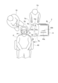
- FIG. 2 is a plan view showing an example of how the cabinet shown in FIG. 1 is used.
- FIG. 1 shows a cabinet 2 according to the present embodiment viewed diagonally from the front.
- the cabinet 2 has a cabinet main body 8 including a top plate 4, a plurality of drawers 6a to 6f, etc., and a top plate 4 of the cabinet main body 8 with a space between the top plate 4 and the top plate 4 in the height direction of the cabinet main body 8 (direction of arrow Z).
- a rotary pallet 10 is provided rotatably with a gap between and is a flat plate parallel to the top plate 4, and is detachably fixed to the front edge 4a of the top plate 4 to rotatably support the rotary pallet 10. It is equipped with a pallet support 12 and the like.
- the cabinet body 8 has a rectangular parallelepiped-shaped outer shell that is wider in the depth direction (direction of arrow Y) than in the left-right direction (direction of arrow X) and extends in the height direction (direction of arrow Z).
- the top plate 4 is fixed to the upper ends of the left and right side plates 14 and 16 and the back plate 17 (see FIG. 2).
- fall prevention fences 18a to 18c made of metal wire bent into a U-shape are fixed on both left and right sides and on the rear side.
- Holders 20a to 20c made of metal wire bent into a U-shape are fixed to the left side plate 14, and can accommodate files, medical charts, and the like.
- Casters 24 are fixed to the four corners of the lower surface of the bottom plate 22 of the cabinet body 8, allowing the cabinet 2 to move on the floor.
- numerals 6a-1 to 6f-1 indicate the handles of the drawers 6a to 6f.
- a housing section 25 is formed below the top plate 4 and can accommodate, for example, a notebook or tablet computer, and the front edge 4a of the top plate 4, which is open without being restrained by a side plate, etc., is used.
- the pallet support 12 is fixed thereto. That is, a housing part 25 is provided below the top plate 4, and a part of the pallet support 12 is housed in the housing part 25.
- the rotating pallet 10 is formed of synthetic resin into a substantially heart shape, and its rotation center Rc is eccentric with respect to the top plate 4 and the rotating pallet 10 itself.
- the rotating pallet 10 can be arbitrarily set to a storage position where it substantially overlaps within the area of the top plate 4 and a position where it projects to the outside of the top plate 4 by its rotation. The degree of force required to rotate the rotating pallet 10 will be described later.
- FIG. 2 shows the rotating pallet 10 in the storage position. In the storage position, only a small portion of the rotating pallet 10 protrudes outside the top plate 4, and is almost within the area of the top plate 4.
- the rotation center Rc of the rotating pallet 10 is eccentric with respect to the top plate 4, being located at the front right corner of the four corners of the top plate 4, and relative to the rotating pallet 10 itself, it is located at the lower right corner of the approximately heart shape. It is located eccentrically.
- the peripheral edge 10a of the rotating pallet 10 consists of two straight parts 10b and 10c, convex and smooth curved parts 10d, 10e, and 10f, and a concave and smooth curved part 10g, and there are no sharp parts.
- the size of the rotating pallet 10 in this embodiment generally follows the rectangular shape of the top plate 4, and the width W1 in the depth direction is 400 mm, the width W2 in the left and right direction is 340 mm, and the convex curved portions 10e and 10f.
- the width W3 is 230 mm.
- the pallet support 12 includes a U-shaped base member 26 that engages with the front edge 4a of the top plate 4, and a U-shaped base member 26 that is fixed to the upper surface 26a of the base member 26 and extends in the vertical direction.
- a support shaft 28 extending to the base member 26, a tightening member 30 attached to the lower surface 26b of the base member 26, a cylindrical lower spacer 32 inserted into the support shaft 28, and a cylindrical upper part also inserted into the support shaft 28. It has a spacer 34 and a fixed lid 36 that is inserted (press-fitted) into the upper spacer 34.
- the rotating pallet 10 is formed with an insertion hole 10h through which the support shaft 28 is inserted.
- the rotating pallet 10 is inserted into the support shaft 28, and then the upper spacer 34 is inserted into the support shaft 28, and the fixed lid 36 is inserted into the upper spacer 34.
- the rotating pallet 10 is rotatably supported.
- the center of the support shaft 28 becomes the rotation center Rc.
- the rotation of the rotating pallet 10 is maintained at an arbitrary position by the clamping friction between the lower spacer 32 and the upper spacer 34.
- the degree of clamping friction that is, the degree of force necessary to rotate the rotating pallet 10 is such that it rotates easily when it comes into contact with a part of the human body such as a hand or an arm, or a surrounding object, and no external force is applied. This is enough to prevent it from rotating unexpectedly.
- the tightening member 30 includes a screw shaft 38 that is screwed into a screw hole formed in the lower surface 26 of the base member 26, a pressing pad 40 fixed to the upper end of the screw shaft 38, and a horizontal
- the operating lever 42 is slidably disposed through the shaft 38 and rotates the screw shaft 38.
- the tightening adjustment amount t in this embodiment is set to 28 to 14 mm.
- the thickness m of the rotating pallet 10 in this embodiment is 14 mm
- the gap h from the upper surface 4b of the top plate 4 to the lower surface 10i of the rotating pallet 10 is 72 mm. Therefore, even if various objects are placed on the upper surface 4b of the top plate 4, no interference occurs when the rotating pallet 10 rotates.
- FIG. 5(a) shows a state in which the cabinet body 8 is rotated counterclockwise by 90 degrees from the storage position shown in FIG. 2, and the amount of protrusion from the front surface of the cabinet body 8 is L1.
- FIG. 5(b) shows a state further rotated 90 degrees counterclockwise from the state shown in FIG. 5(a), and the amount of protrusion from the front surface of the cabinet main body 8 is L2 (>L1).
- FIG. 5C shows a state further rotated counterclockwise by 90 degrees from the state shown in FIG. 5B, and the amount of protrusion from the right side surface of the cabinet body 8 is L3 ( ⁇ L2).
- the cabinet 2 can be set at an appropriate rotational position depending on the location where the cabinet 2 is used and the convenience of the user. In this way, the rotating pallet 10 substantially has the function of arbitrarily expanding the mounting area of the top plate 4.
- the cabinet main body 8 is located at a distance from the patient P, and the assistant As can open and close each of the drawers 6a to 6f. Further, since the cabinet body 8 is separated from the patient P, a safe work space exists at the feet of the assistant As.
- the rotating pallet 10 is set such that the curved portion 10f is close to the face Pf of the patient P, and the curved portion 10e is close to the assistant As who is standing. Since there are no corners on the rotating pallet 10, there is no fear of injury to the patient P or the assistant As even if they accidentally come into contact with it. Therefore, the rotating pallet 10 can be brought as close as possible to the patient's P's face Pf.
- instruments 44c and 44d scheduled for treatment are placed so that they can be quickly handed to the sitting dentist Dr by the assistant As. For example, the covering 45 removed from the patient P is placed in the placement area Sb on the side of the curved portion 10f.
- the dentist Dr can immediately place the removed covering 45 on the area on the side of the curved portion 10f close to the face Pf of the patient P without having to extend his hand greatly.
- Reference numerals 44a and 44b indicate instruments placed on the upper surface 4b of the top plate 4. If the rotating pallet 10 is transparent or translucent, there will be no problem that the equipment placed on the top surface 4b of the top plate 4 cannot be seen depending on the rotational position of the rotating pallet 10.
- the rotary pallet 10 has a mounting surface (upper surface 10j) in which the mounting area Sa and the mounting area Sb are connected in an L-shape, so that instruments necessary for treatment can be placed thereon.
- the area can be clearly distinguished from the area where objects to be discharged during treatment are placed.
- the dentist Dr and the assistant As It is possible to improve workability.
- the rotating pallet 10 does not have sharp corners, so even if your hand or arm accidentally hits it, it will not hurt, and since the rotating pallet 10 rotates at the same time as it hits, the rotating pallet 10 will not be damaged. Not at all. The same applies if an object hits the rotating pallet 10 while the cabinet 2 is being moved.
- the cabinet 2 When the rotating pallet 10 is not used, by setting it in the storage position shown in FIG. 2, the cabinet 2 can be placed and moved without increasing the space occupied in the horizontal plane.
- the rotary pallet 10 is supported by the pallet support 12 that is detachable from the top plate 4, but it may be rotatably supported by a shaft integrally fixed to the top plate 4.
- the configuration in which it is supported by the removable pallet support 12 has the advantage that the rotating pallet 10 can be easily attached to an existing cabinet and can be removed and returned to its original configuration when unnecessary.
- the shape of the rotating pallet 10 and the position (eccentric position) of the rotation center Rc are not limited to those described above, and can be appropriately determined within a range that provides the function of expanding the placement area with respect to the top plate 4 described above. If the top plate 4 has a larger area than the cross-sectional area of the cabinet body 8 below, the pallet support 12 can be fixed to the protruding edge of the top plate 4 even if the storage part 25 is not present. can.
- the above embodiment shows an example of use in a dental clinic, it can be similarly used in examinations and treatments in internal medicine and surgery departments in hospitals, and is also suitable in fields such as assembly of precision parts.
Landscapes
- Health & Medical Sciences (AREA)
- Nursing (AREA)
- Life Sciences & Earth Sciences (AREA)
- Animal Behavior & Ethology (AREA)
- General Health & Medical Sciences (AREA)
- Public Health (AREA)
- Veterinary Medicine (AREA)
- Dental Tools And Instruments Or Auxiliary Dental Instruments (AREA)
Priority Applications (1)
| Application Number | Priority Date | Filing Date | Title |
|---|---|---|---|
| JP2024533765A JPWO2024014533A1 (https=) | 2022-07-14 | 2023-07-14 |
Applications Claiming Priority (2)
| Application Number | Priority Date | Filing Date | Title |
|---|---|---|---|
| JP2022-113562 | 2022-07-14 | ||
| JP2022113562 | 2022-07-14 |
Publications (1)
| Publication Number | Publication Date |
|---|---|
| WO2024014533A1 true WO2024014533A1 (ja) | 2024-01-18 |
Family
ID=89536872
Family Applications (1)
| Application Number | Title | Priority Date | Filing Date |
|---|---|---|---|
| PCT/JP2023/026028 Ceased WO2024014533A1 (ja) | 2022-07-14 | 2023-07-14 | キャビネット |
Country Status (2)
| Country | Link |
|---|---|
| JP (1) | JPWO2024014533A1 (https=) |
| WO (1) | WO2024014533A1 (https=) |
Citations (4)
| Publication number | Priority date | Publication date | Assignee | Title |
|---|---|---|---|---|
| JPS60222055A (ja) * | 1984-04-19 | 1985-11-06 | 工業技術院長 | 身体障害者用キツチネツトワゴン |
| JP2005161079A (ja) * | 2003-02-19 | 2005-06-23 | Olympus Corp | 処置具保持具及びこの保持具を設置するハンガー支柱 |
| US20160095779A1 (en) * | 2014-10-06 | 2016-04-07 | U.S. Patent Innovations Llc | Medical Trolley Cart |
| JP2022095070A (ja) * | 2020-12-16 | 2022-06-28 | 株式会社イトーキ | 第2天板を有するカート |
-
2023
- 2023-07-14 JP JP2024533765A patent/JPWO2024014533A1/ja active Pending
- 2023-07-14 WO PCT/JP2023/026028 patent/WO2024014533A1/ja not_active Ceased
Patent Citations (4)
| Publication number | Priority date | Publication date | Assignee | Title |
|---|---|---|---|---|
| JPS60222055A (ja) * | 1984-04-19 | 1985-11-06 | 工業技術院長 | 身体障害者用キツチネツトワゴン |
| JP2005161079A (ja) * | 2003-02-19 | 2005-06-23 | Olympus Corp | 処置具保持具及びこの保持具を設置するハンガー支柱 |
| US20160095779A1 (en) * | 2014-10-06 | 2016-04-07 | U.S. Patent Innovations Llc | Medical Trolley Cart |
| JP2022095070A (ja) * | 2020-12-16 | 2022-06-28 | 株式会社イトーキ | 第2天板を有するカート |
Also Published As
| Publication number | Publication date |
|---|---|
| JPWO2024014533A1 (https=) | 2024-01-18 |
Similar Documents
| Publication | Publication Date | Title |
|---|---|---|
| AU2015328645B2 (en) | Organizer for surgical instruments and items used during surgery | |
| US8453977B2 (en) | Neutral field tray system | |
| TWI479975B (zh) | The protective cover structure of the flat panel display device | |
| US7980517B2 (en) | Neutral field tray system | |
| JP2005506110A5 (https=) | ||
| JPH045156Y2 (https=) | ||
| BR112013028176B1 (pt) | dispositivo de dispensação | |
| US6940713B2 (en) | Portable computer standing support structure | |
| TW200403135A (en) | Tool case with cover member support | |
| US6634499B2 (en) | Tray for medical instrumentation | |
| CN110072486A (zh) | 用于传递、计数、存放和处置手术器械的托盘系统 | |
| WO2024014533A1 (ja) | キャビネット | |
| US7975846B2 (en) | Sharps holding device | |
| US20160067134A1 (en) | Remote control housing systems, devices, and methods, and protective covers for remote controls | |
| TWI343517B (en) | Electronic device | |
| US20210322245A1 (en) | Braking device for operating table base | |
| JP7211828B2 (ja) | メス載置具 | |
| CN108534748B (zh) | 激光测量机 | |
| CN112527078A (zh) | 一种便于携带办公的个人计算机支座 | |
| KR200150306Y1 (ko) | 의료용 테이블 | |
| KR200369928Y1 (ko) | 약포지의 개구 단부 개방장치 | |
| KR200274461Y1 (ko) | 치료용 유니트 | |
| JP2012217685A (ja) | ナースカート及びこれを備えた統合カート | |
| CN212439206U (zh) | 一种呼吸科用便于携带的护理托盘 | |
| US20050181325A1 (en) | Dental cart |
Legal Events
| Date | Code | Title | Description |
|---|---|---|---|
| 121 | Ep: the epo has been informed by wipo that ep was designated in this application |
Ref document number: 23839702 Country of ref document: EP Kind code of ref document: A1 |
|
| WWE | Wipo information: entry into national phase |
Ref document number: 2024533765 Country of ref document: JP |
|
| NENP | Non-entry into the national phase |
Ref country code: DE |
|
| 122 | Ep: pct application non-entry in european phase |
Ref document number: 23839702 Country of ref document: EP Kind code of ref document: A1 |