WO2024014247A1 - Power feeding device, connection member, and installation method - Google Patents
Power feeding device, connection member, and installation method Download PDFInfo
- Publication number
- WO2024014247A1 WO2024014247A1 PCT/JP2023/022999 JP2023022999W WO2024014247A1 WO 2024014247 A1 WO2024014247 A1 WO 2024014247A1 JP 2023022999 W JP2023022999 W JP 2023022999W WO 2024014247 A1 WO2024014247 A1 WO 2024014247A1
- Authority
- WO
- WIPO (PCT)
- Prior art keywords
- electric wire
- arms
- trolley
- opening
- pair
- Prior art date
Links
- 238000000034 method Methods 0.000 title claims description 9
- 238000009434 installation Methods 0.000 title description 3
- 210000000078 claw Anatomy 0.000 claims description 36
- 238000010276 construction Methods 0.000 claims description 22
- 238000010292 electrical insulation Methods 0.000 claims description 13
- 238000005192 partition Methods 0.000 description 41
- 230000004048 modification Effects 0.000 description 21
- 238000012986 modification Methods 0.000 description 21
- 230000001105 regulatory effect Effects 0.000 description 15
- 229920003002 synthetic resin Polymers 0.000 description 7
- 239000000057 synthetic resin Substances 0.000 description 7
- 238000003780 insertion Methods 0.000 description 6
- 230000037431 insertion Effects 0.000 description 6
- 238000009413 insulation Methods 0.000 description 5
- 229910052751 metal Inorganic materials 0.000 description 3
- 239000002184 metal Substances 0.000 description 3
- 238000010586 diagram Methods 0.000 description 2
- 230000000149 penetrating effect Effects 0.000 description 2
- 230000035515 penetration Effects 0.000 description 2
- RYGMFSIKBFXOCR-UHFFFAOYSA-N Copper Chemical compound [Cu] RYGMFSIKBFXOCR-UHFFFAOYSA-N 0.000 description 1
- 229910052782 aluminium Inorganic materials 0.000 description 1
- XAGFODPZIPBFFR-UHFFFAOYSA-N aluminium Chemical compound [Al] XAGFODPZIPBFFR-UHFFFAOYSA-N 0.000 description 1
- 239000004020 conductor Substances 0.000 description 1
- 229910052802 copper Inorganic materials 0.000 description 1
- 239000010949 copper Substances 0.000 description 1
- 230000005611 electricity Effects 0.000 description 1
- 239000000463 material Substances 0.000 description 1
Images


Classifications
-
- B—PERFORMING OPERATIONS; TRANSPORTING
- B60—VEHICLES IN GENERAL
- B60M—POWER SUPPLY LINES, AND DEVICES ALONG RAILS, FOR ELECTRICALLY- PROPELLED VEHICLES
- B60M1/00—Power supply lines for contact with collector on vehicle
- B60M1/12—Trolley lines; Accessories therefor
- B60M1/20—Arrangements for supporting or suspending trolley wires, e.g. from buildings
- B60M1/24—Clamps; Splicers; Anchor tips
-
- B—PERFORMING OPERATIONS; TRANSPORTING
- B60—VEHICLES IN GENERAL
- B60M—POWER SUPPLY LINES, AND DEVICES ALONG RAILS, FOR ELECTRICALLY- PROPELLED VEHICLES
- B60M1/00—Power supply lines for contact with collector on vehicle
- B60M1/12—Trolley lines; Accessories therefor
- B60M1/28—Manufacturing or repairing trolley lines
Definitions
- the present disclosure generally relates to a power supply device, a connection member, and a construction method, and more particularly relates to a power supply device having a trolley wire, a connection member used in this power supply device, and a construction method of this power supply device.
- the insulated trolley described in Patent Document 1 includes a tightening device, a first connection block, and a second connection block.
- the tightening device holds a first end of a first insulated trolley wire and a second end of a second insulated trolley wire.
- the first connection block holds a third end opposite the first end of the first insulated trolley wire.
- the second connection block holds a fourth end opposite the second end of the second insulated trolley wire.
- An object of the present disclosure is to provide a power supply device, a connection member, and a construction method that can simplify the work of installing a trolley wire.
- a power supply device supplies power to a mobile device.
- the mobile device is movable along a rail.
- the power supply device includes a trolley wire and a connection member.
- the trolley wire includes an electric wire.
- the electric wire is used as a power supply path to the mobile device by being electrically connected to the mobile device.
- the connecting member is a member for arranging the trolley wire along the rail.
- the connection member includes a terminal portion and a body.
- the terminal portion is electrically connected to the electric wire.
- the body holds the terminal portion.
- the terminal portion has a pair of arms and an opening/closing opening.
- the opening/closing opening is provided between the pair of arms, and the opening interval is changed by an external force applied between the pair of arms.
- the pair of arms sandwich the electric wire inserted into the opening/closing opening from the front of the opening/closing opening while changing the opening interval of the opening/closing opening.
- a connection member according to one aspect of the present disclosure is used in the power supply device.
- a construction method is a construction method of a power supply device that supplies power to a mobile device.
- the mobile device is movable along a rail.
- the power supply device includes a trolley wire and a connection member.
- the trolley wire includes an electric wire.
- the electric wire is used as a power supply path to the mobile device by being electrically connected to the mobile device.
- the connecting member is a member for arranging the trolley wire along the rail.
- the connection member includes a terminal portion and a body.
- the terminal portion is electrically connected to the electric wire.
- the body holds the terminal portion.
- the terminal portion has a pair of arms and an opening/closing opening. The opening/closing opening is provided between the pair of arms, and the opening interval is changed by an external force applied between the pair of arms.
- the construction method includes a first step and a second step.
- the body of the connecting member is attached to the rail.
- the electric wire is inserted into the opening from the front of the opening and closing, and the electric wire is sandwiched between the pair of arms while changing the opening interval of the opening and closing.
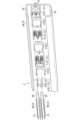
- FIG. 1 is a perspective view of a power supply device according to an embodiment, showing a state before a trolley wire is attached.
- FIG. 2 is a perspective view of the above power supply device after the trolley wire is attached.
- FIG. 3 is a front view of the above power supply device before the trolley wire is attached.
- FIG. 4 is a front view of the above power supply device after the trolley wire is attached.
- FIG. 5 is a sectional view of the trolley wire of the power supply device same as above.
- FIG. 6 is a cross-sectional view taken along line VI-VI in FIG.
- FIG. 7 is a cross-sectional view taken along line VII-VII in FIG.
- FIG. 8 is a cross-sectional perspective view of the above power supply device taken along a plane along the line VIII-VIII of FIG.
- FIG. 9 is a cross-sectional perspective view of the above power supply device taken along a plane along line IX-IX in FIG. 4 and a plane perpendicular to the vertical direction.
- FIG. 10 is a cross-sectional view of a portion of the power supply device and the current collector device.
- FIG. 11 is an exploded perspective view of another portion of the power supply device same as above.
- FIG. 12 is a perspective view of the hanger of the power supply device same as above.
- FIG. 13 is an exploded perspective view of the joint of the power supply device same as above.
- FIG. 14 is a sectional view of a joint of the power supply device same as above.
- FIG. 15 is an exploded perspective view of another joint of the power supply device same as above.
- FIG. 16 is a sectional view of a hanger of a power supply device according to Modification 1.
- FIG. 17 is a cross-sectional view of a trolley wire of a power supply device according to modification 2.
- FIG. 18 is a cross-sectional view of a trolley wire of a power supply device according to modification 3.
- FIG. 19 is a cross-sectional view of a trolley wire of a power supply device according to modification 4.
- FIG. 20A is a side view showing a state in which the opening/closing opening of the terminal portion is closed.
- FIG. 20B is a side view showing a state in which the opening/closing port of the terminal portion is open.
- the power supply device 1 of this embodiment supplies power to a mobile device 9 (see FIG. 10).
- the mobile device 9 is movable along the rail 3.
- the power supply device 1 includes a trolley wire 2 and a connection member.
- the trolley wire 2 has an electric wire 20.
- the electric wire 20 is used as a power supply path to the mobile device 9 by being electrically connected to the mobile device 9 .
- the connecting member is a member for arranging the trolley wire 2 along the rail 3.
- the description will focus on the second joint 7 (see FIGS. 6 and 15), which is an example of the connection member.
- the connecting member (second joint 7) includes a terminal portion 71 and a body 70.
- the terminal portion 71 is electrically connected to the electric wire 20.
- the body 70 holds the terminal portion 71.
- the terminal portion 71 includes a pair of arms 711 and 712 and an opening/closing opening OP1 provided between the pair of arms 711 and 712.
- the opening/closing opening OP1 changes the opening interval by an external force applied between the pair of arms 711 and 712.
- the pair of arms 711 and 712 sandwich the electric wire 20 inserted into the opening/closing opening OP1 from the front of the opening/closing opening OP1 while changing the opening interval of the opening/closing opening OP1 (Figs. 2, 6, 7, 13, 15) reference).
- a worker or the like inserts the electric wire 20 of the trolley wire 2 into the opening/closing opening OP1 from the front, inserts the electric wire 20 between the pair of arms 711 and 712 of the terminal part 71, and then inserts the electric wire 20 into the opening/closing opening OP1 from the front. 20 can be electrically connected to the terminal portion 71. In this way, the work of installing the trolley wire 2 can be simplified.
- the power supply device 1 of this embodiment can be assembled by the following construction method.
- the construction method of this embodiment is a construction method of the power supply device 1 that supplies power to the mobile device 9.
- the mobile device 9 is movable along the rail 3.
- the power supply device 1 includes a trolley wire 2 and a connection member.
- the trolley wire 2 has an electric wire 20.
- the electric wire 20 is used as a power supply path to the mobile device 9 by being electrically connected to the mobile device 9 .
- the connecting member is a member for arranging the trolley wire 2 along the rail 3.
- the description will focus on the second joint 7 (see FIGS. 6 and 15), which is an example of the connection member.
- the connecting member (second joint 7) includes a terminal portion 71 and a body 70.
- the terminal portion 71 is electrically connected to the electric wire 20.
- the body 70 holds the terminal portion 71.
- the terminal portion 71 includes a pair of arms 711 and 712 and an opening/closing opening OP1 provided between the pair of arms 711 and 712.
- the opening/closing opening OP1 changes the opening interval by an external force applied between the pair of arms 711 and 712.
- the construction method includes a first step and a second step. In the first step, the body 70 of the connecting member is attached to the rail 3.
- the electric wire 20 is inserted into the opening/closing opening OP1 from the front of the opening/closing opening OP1, and the electric wire 20 is sandwiched between the pair of arms 711 and 712 while changing the opening interval of the opening/closing opening OP1.
- the power supply device 1 of this embodiment supplies power to the mobile device 9.
- the mobile device 9 is movable along the rail 3.
- the power supply device 1 includes a trolley wire 2 and a plurality of supporters S1.
- the trolley wire 2 includes an electric wire 20 and a covering member 21.
- the electric wire 20 is used as a power supply path to the mobile device 9 by being electrically connected to the mobile device 9 .
- the covering member 21 has electrical insulation properties.
- the covering member 21 covers a part of the electric wire 20.
- a plurality of supporters S1 are arranged along the rail 3 and support the trolley line 2.
- the covering member 21 covers at least the rear surface of the electric wire 20 and protrudes rearward from the rear surface of the electric wire 20.
- the distance I1 (thickness) in the front-rear direction from the rear surface of the electric wire 20 to the rear end of the covering member 21 is longer than the width (width W1 or W2) of the electric wire 20.
- the interval I1 is longer than the width W1 or W2, that is, the trolley wire 2 is relatively long in the front-rear direction. Therefore, the possibility that the trolley wire 2 is bent is reduced.
- the trolley wire 2 when attaching the trolley wire 2 to the supporter S1, force may be applied to the trolley wire 2 and the trolley wire 2 may be bent. Furthermore, when the mobile device 9 pushes the electric wire 20 via a current collector 90 (described later), the trolley wire 2 may be bent. Therefore, by making the trolley wire 2 relatively long in the front-rear direction as described above, it is possible to reduce the possibility that the trolley wire 2 will bend.
- up and down merely represent the relative positional relationship of the configuration of the power supply device 1, and are not intended to limit the direction in which the power supply device 1 is used. Therefore, for example, the power supply device 1 may be used in an orientation in which "front” in the present disclosure refers to top, bottom, rear, left, or right.
- the power supply device 1 supplies power to the mobile device 9 (see FIG. 10).
- the mobile device 9 is, for example, a self-propelled trolley or a hoist.
- the mobile device 9 receives power from an electric wire 20 installed on the rail 3 (see FIG. 3).
- the mobile device 9 moves along the rail 3 using the electric power obtained in this way as a power source.
- the power supply device 1 and the mobile device 9 are used, for example, in a distribution warehouse or a factory.
- the mobile device 9 is used, for example, as a transport device for transporting articles.
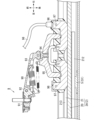
- the mobile device 9 of this embodiment includes a current collector 90, and a plurality of current collectors 97 of the current collector 90 contact the electric wire 20. Further, the electric wire 20 is electrically connected to an external power source via a power line C1 (see FIG. 8). As a result, power is supplied from the external power source to the mobile device 9 via the electric wire 20 and the current collector 90.
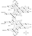
- FIG. 4 is an overall view of the power supply device 1. As shown in FIG. 4, the power supply device 1 is used together with a plurality of (two) rails 3. The power supply device 1 includes a plurality (eight) of trolley wires 2 and a plurality (nine) of supporters S1.
- the nine supporters S1 include two first end members 4, three hangers 5, one first joint 6, one second joint 7, and two second end members 8. Note that when the two first end members 4 and the two second end members 8 are not distinguished, they are each referred to as "end member E1.” That is, the first terminating member 4 and the second terminating member 8 are each an example of the terminating member E1.
- the termination member E1 supports the right end or left end of the electric wire 20. Furthermore, when the first joint 6 and the second joint 7 are not distinguished, they are each referred to as a "joint J1.” That is, the first joint 6 and the second joint 7 are each an example of the joint J1. Joint J1 electrically connects two electric wires 20.
- the first end member 4 and the first and second joints 6 and 7 are each an example of a connecting member.
- the connection member is a member that is responsible for at least one of relaying the electrical connection between the power line C1 and the electric wire 20, and relaying the electrical connection between the electric wires 20.
- the plurality of connection members are arranged in the left-right direction.
- trolley wires 2 may be distinguished and referred to as trolley wires 2A, 2B, 2C, 2D, 2E, 2F, 2G, and 2H.
- the two rails 3 may be distinguished and referred to as rails 3A and 3B.
- the trolley wire 2 includes an electric wire 20 and a covering member 21.
- the electric wire 20 is made of a conductive material such as copper.
- the covering member 21 is made of electrically insulating synthetic resin or the like.
- the longitudinal direction of the electric wire 20 is along the left-right direction.
- the covering member 21 covers a part of the electric wire 20.
- the covering member 21 is provided from the left end to the right end of the electric wire 20.
- a worker or the like uses a tool such as a cable cutter at the construction site of the power supply device 1 to peel off a portion of the covering member 21, for example, both end portions. Accordingly, in the power supply device 1 installed at the construction site, the covering member 21 is provided only in a part of the section between both ends of the electric wire 20 in the left-right direction (from the left end to the right end).
- a tool such as a cable cutter
- a portion including the right end of the electric wire 20 is not provided with the covering member 21 and is exposed over the entire circumference.
- the exposed portion of the electric wire 20 is electrically connected to the terminal portion 41 of the connection member (for example, the first termination member 4 in FIG. 8).
- the trolley wire 2A and the trolley wire 2B are aligned in the vertical direction. Furthermore, the respective longitudinal directions of the trolley wire 2A and the trolley wire 2B are along the same direction (left-right direction). That is, the trolley wire 2A and the trolley wire 2B are arranged in parallel.
- the trolley wire 2A and the trolley wire 2B are connected to each other at the covering member 21.
- the covering member 21 of the trolley wire 2A is connected to the covering member 21 of the trolley wire 2B.
- these two covering members 21 are connected via a connecting portion 22.
- the connecting portion 22 is configured integrally with the two covering members 21 described above. Thereby, the two covering members 21 are integrally formed.
- the trolley wire 2C (see FIG. 4) and the trolley wire 2D are vertically lined up and connected to each other at the covering member 21.
- the trolley wire 2E and the trolley wire 2F are vertically lined up and connected to each other at the covering member 21.
- the trolley wire 2G and the trolley wire 2H are vertically lined up and connected to each other at the covering member 21.
- trolley wires 2A, 2C, 2E, and 2G are lined up in this order.
- trolley wires 2B, 2D, 2F, and 2H are lined up in this order.
- the current collector 90 includes four current collectors 97 (only two are shown in FIG. 10). Each current collector 97 is in contact with the electric wire 20 of one of the trolley wires 2 depending on the position of the current collector 90. Two of the four current collectors 97 are in contact with the electric wires 20 of one or two of the trolley wires 2 among the trolley wires 2A, 2C, 2E, and 2G depending on the position of the current collector 90. There is. The remaining two current collectors 97 are in contact with the electric wires 20 of one or two of the trolley wires 2 among the trolley wires 2B, 2D, 2F, and 2H depending on the position of the current collector 90.
- the current collector 90 moves to the right from a state in which the four current collectors 97 are in contact with the electric wires 20 of the trolley wires 2A, 2B, the four current collectors 97 contact the electric wires 20 of the trolley wires 2A, 2B, The state changes to a state in which it is in contact with the electric wires 20 of 2C and 2D. As the current collector 90 moves further to the right, the four current collectors 97 are brought into contact with the respective electric wires 20 of the trolley wires 2C and 2D.
- the shape of the electric wire 20 is the same among the plurality of trolley wires 2. As shown in FIG. 5, the electric wire 20 has a contact portion 201 and a protrusion 202.
- the contact portion 201 is formed into a plate shape whose thickness direction is along the front-rear direction.
- the longitudinal direction of the contact portion 201 is along the left-right direction.
- Contact portion 201 has a front surface 2010. In a cross section perpendicular to the left-right direction, the center portion of the front surface 2010 is recessed toward the rear. Front surface 2010 is exposed to the outside. More specifically, the front surface 2010 is exposed without being covered by the covering member 21 in any section between both ends of the contact portion 201 in the left-right direction.
- the vertical width W2 of the protruding portion 202 is smaller than the vertical width W1 of the contact portion 201.
- the vertical width W1 of the contact portion 201 is the maximum width of the electric wire 20 in the vertical direction.
- the protruding part 202 protrudes from the rear surface of the contact part 201 and is formed along the longitudinal direction of the electric wire 20. More specifically, in a cross section perpendicular to the left-right direction, the protruding portion 202 protrudes from the center of the rear surface of the contact portion 201.
- the protruding portion 202 is a portion sandwiched between the pair of arms of the terminal portion along the longitudinal direction of the electric wire 20.
- the protruding portion 202 is sandwiched between the pair of arms 411 and 412 of the terminal portion 41.
- the pair of arms 411, 412 sandwich the protrusion 202 inserted into the opening/closing opening OP1 between the pair of arms 411, 412.
- the width of the opening between the pair of arms 411 and 412 can be made smaller compared to the case where the entire electric wire 20 is sandwiched between the pair of arms 411 and 412. Therefore, it becomes easier for workers and the like to install the electric wires 20.
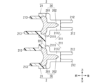
- the covering member 21 includes a covering main body 211, a plurality of (two in FIG. 5) rear ribs 212, and a plurality of (two in FIG. 5) front ribs 213.
- the covering body 211 covers at least the rear surface of the electric wire 20.
- the covering body 211 is formed along the shape of the electric wire 20. More specifically, the covering body 211 is a portion of the covering member 21 where the thickness measured from the surface of the electric wire 20 is equal to or less than a threshold value. In the present embodiment, a portion of the covering member 21 whose thickness as measured from the surface of the electric wire 20 exceeds the threshold corresponds to the rear rib 212 or the front rib 213.
- the covering main body 211 of this embodiment includes a front side part 2111 and a rear side part 2112.
- the front side portion 2111 covers an area of the contact portion 201 excluding a part of the front surface 2010.
- the front side portion 2111 has a C-shape with an open front.
- the rear side portion 2112 covers the entire protrusion 202 .
- the shape of the rear side portion 2112 is a U-shape with an open front.
- the covering member 21 has a window 2011 that exposes the front surface of the electric wire 20, more specifically, the front surface 2010 of the contact portion 201.
- Window 2011 is an opening.
- the window 2011 is provided in the covering body 211 of the covering member 21.
- the two rear ribs 212 protrude rearward from the covering body 211. More specifically, the two rear ribs 212 protrude from the rear side 2112 of the covering body 211.
- the rear rib 212 extends in the longitudinal direction (left-right direction) of the electric wire 20.
- One of the two rear ribs 212 protrudes from the upper end of the rear side portion 2112.
- the other of the two rear ribs 212 protrudes from the lower end of the rear side portion 2112.
- the protrusion amounts of the two rear ribs 212 are equal to each other. "Equal" as used in the present disclosure is not limited to completely equal states, but also includes different states within a range that poses no practical problem.
- the two front ribs 213 protrude forward from the covering body 211. More specifically, the two front ribs 213 protrude from the front side 2111 of the covering body 211.
- the two front ribs 213 protrude forward from the edge of the covering body 211 forming the window 2011 and extend in the longitudinal direction (horizontal direction) of the electric wire 20.
- the two front ribs 213 are opposed to each other. More specifically, one front rib 213T (first front rib) of the two front ribs 213 projects forward from above the window 2011.
- the other front rib 213U (second front rib) of the two front ribs 213 projects forward from below the window 2011. In this way, since the front ribs 213 are provided on the upper and lower sides of the window 2011, these two front ribs 213 prevent the operator's fingers and the like from moving closer to the electric wire 20. Therefore, the possibility that the operator's fingers or the like will come into contact with the electric wire 20 can be reduced. Furthermore, the insulation distance between the two electric wires 20 is extended compared to the case where there is no front rib 213U.
- the amount of protrusion of the front rib 213U is larger than the amount of protrusion of the front rib 213T. In this way, since the amount of protrusion of the front rib 213U is relatively large, the insulation distance between the two electric wires 20 is relatively long.
- the shapes of the trolley wires 2C, 2E, and 2G are the same as the trolley wire 2A.
- the shapes of the trolley wires 2B, 2D, 2F, and 2H are different from the shape of the trolley wire 2A with respect to the shapes of the two front ribs 213. More specifically, the trolley wire 2B is vertically symmetrical with respect to the trolley wire 2A.
- the shapes of the trolley wires 2B, 2D, 2F, and 2H are the same.
- One front rib 213V of the two front ribs 213 of the trolley wire 2B projects forward from above the window 2011.
- the other front rib 213W of the two front ribs 213 projects forward from below the window 2011.
- the amount of protrusion of the front rib 213V is larger than the amount of protrusion of the front rib 213W.
- the covering member 21 of the trolley wire 2A is referred to as a first covering member.
- the covering member 21 of the trolley wire 2B is called a second covering member.
- the first covering member is arranged above the second covering member.
- the first covering member and the second covering member each have two front ribs 213 facing each other.
- the two front ribs 213 protrude forward from the edge of the covering member 21 that forms the window 2011 and extend in the length direction (horizontal direction) of the electric wire 20.
- the front rib 213U located on the inside protrudes more than the front rib 213T located on the outside of the first covering member and the second covering member.
- the front rib 213V located on the inner side of the first covering member and the second covering member has a larger protrusion amount than the front rib 213W located on the outer side of the first covering member and the second covering member.
- the thickness from the rear surface of the electric wire 20 to the rear end of the covering member 21 is longer than the width of the electric wire 20.
- the thickness from the rear surface of the electric wire 20 to the rear end of the covering member 21 is, more specifically, the distance I1 from the rear surface of the electric wire 20 to the rear end of the covering member 21 in the front-back direction.
- the width of the electric wire 20 that is compared with the interval I1 is the width of a predetermined portion of the electric wire 20 in the vertical direction.
- the width of the electric wire 20 to be compared with the interval I1 may be the largest width W1 among the widths of each region of the electric wire 20. More specifically, the width of the electric wire 20 compared with the interval I1 may be the maximum width W1 of the electric wire 20 in the vertical direction.
- the width of the electric wire 20 that is compared with the interval I1 may be the width W2 of the protrusion 202. More specifically, the width of the electric wire 20 that is compared with the interval I1 may be the width W2 of the protrusion 202 in the vertical direction.
- the interval I1 is longer than either of the widths W1 and W2. Further, the amount P1 of the rear rib 212 protruding from the covering body 211 in the front-rear direction is longer than either of the widths W1 and W2.
- the rail 3A is arranged to the left of the rail 3B.
- the longitudinal direction of each rail 3 is along the left-right direction.
- rails 3A and 3B have different lengths in the left-right direction, they have the same configuration in other respects.
- the configuration of the rail 3A will be described below with reference to FIG. 2.
- the rail 3 is installed on the travel route of the mobile device 9 (see FIG. 10).
- the rail 3 is fixed to the frame of a building that constitutes a distribution warehouse or a factory, for example.
- the rail 3 is made of aluminum, for example.
- the rail 3 has a C-shape with an open front.
- the rail 3 has a bottom wall 31, a first side wall 32, and a second side wall 33.
- the thickness direction of the bottom wall 31 is along the front-rear direction.
- a plurality of supporters S1 are fixed to the bottom wall 31. More specifically, a plurality of supporters S1 are fixed to the bottom wall 31 by, for example, screws.
- the first side wall 32 projects forward from the upper end of the bottom wall 31.
- the front end of the first side wall 32 is bent downward.
- the second side wall 33 projects forward from the lower end of the bottom wall 31.
- the front end of the second side wall 33 is bent upward.
- Supporters As shown in FIGS. 3 and 4, a plurality of (seven in FIG. 3) supporters S1 are fixed to the rail 3A in a row in the left-right direction. More specifically, the seven supporters S1 fixed to the rail 3A are, in order from the left, the second end member 8, the hanger 5, the second joint 7, the hanger 5, the first joint 6, the hanger 5, and the first end. This is member 4.
- a plurality of (two in FIG. 3) supporters S1 are fixed to the rail 3B. More specifically, the two supporters S1 fixed to the rail 3B are the second end member 8 and the first end member 4 in order from the left.
- the plurality of supporters S1 support the plurality of trolley wires 2. More specifically, seven supporters S1 fixed to the rail 3A support the trolley wires 2A to 2F. Two supporters S1 fixed to the rail 3B support the trolley wires 2G and 2H.
- FIG. 8 is a diagram including a cross-sectional perspective view of the first termination member 4.
- FIG. 11 shows an exploded perspective view of the first end member 4 and a perspective view of the second end member 8.
- the first and second end members 4 and 8 attached to the rail 3B support the trolley wires 2G and 2H. In contrast, the first and second end members 4, 8 attached to the rail 3A support another trolley wire 2.
- the first and second end members 4 and 8 attached to the rail 3B will be described below with reference to FIGS. 8 and 11.
- the shape of the second end member 8 attached to the rail 3A is the same as the shape of the second end member 8 attached to the rail 3B.
- the shape of the first end member 4 attached to the rail 3A is the same as the shape of the first end member 4 attached to the rail 3B.
- the first end member 4 includes a body 40, a plurality of (two in FIG. 11) terminal portions 41, an insulating cover 42, and a fastening member 43.
- the fastening member 43 is, for example, a screw or a bolt.
- the body 40 is made of synthetic resin, for example.
- the body 40 has electrical insulation properties.
- the body 40 is fixed to the rail 3 using, for example, bolts 44 and nuts 45.
- the shape of the body 40 is a rectangular parallelepiped.
- the body 40 has a space inside.
- the body 40 has a bottom wall 400, a first side wall 401, a second side wall 402, a third side wall 403, a first partition wall 404, and a second partition wall 405.
- the shape of the bottom wall 400 is rectangular.
- the thickness direction of the bottom wall 400 is along the front-back direction.
- the body 40 further includes a plurality of (two in FIG. 8) positioning pieces 406.
- a plurality of positioning pieces 406 protrude forward from the bottom wall 400.
- the plurality of positioning pieces 406 position the terminal portion 41. That is, the terminal portion 41 is positioned at a position where it contacts the front surface of the plurality of positioning pieces 406.
- the first terminal member 4 has two terminal parts 41, one terminal part 41 is positioned by two positioning pieces 406, and the other terminal part 41 is positioned by another two positioning pieces 406. It is positioned by 406.
- the first side wall 401 projects forward from the upper end of the bottom wall 400.
- the body 40 further includes a claw portion 4010.
- the claw portion 4010 protrudes from the first side wall 401.
- the claw portion 4010 hooks the trolley wire 2 (see FIG. 9). More specifically, the claw portion 4010 hooks the covering member 21 of the trolley wire 2. Thereby, the claw portion 4010 restricts forward movement of the trolley wire 2.
- the second side wall 402 protrudes forward from the lower end of the bottom wall 400.
- the body 40 further includes a claw portion 4020.
- the claw portion 4020 protrudes from the second side wall 402.
- the claw portion 4020 hooks the trolley wire 2. More specifically, the claw portion 4020 hooks the covering member 21 of the trolley wire 2. Thereby, the claw portion 4020 restricts forward movement of the trolley wire 2.
- the third side wall 403 projects forward from the right end of the bottom wall 400.
- the third side wall 403 has two guide grooves 4030 for guiding the current collector 97 of the current collector 90.
- the first partition wall 404 protrudes forward from a position between the first side wall 401 and the second side wall 402 of the bottom wall 400.
- the thickness direction of the first partition wall 404 is along the up-down direction.
- the first partition wall 404 partitions a space where one of the two power lines C1 and the trolley wire 2G are arranged from a space where the other of the two power lines C1 and the trolley wire 2H are arranged.
- the first partition wall 404 has a boss portion 407.
- the insulating cover 42 is made of, for example, synthetic resin.
- the insulating cover 42 has electrical insulation properties.
- the shape of the insulating cover 42 is a rectangular plate.
- the thickness direction of the insulating cover 42 is along the front-rear direction.
- Two electric wires 20 are arranged in front of the insulating cover 42.
- Two power lines C1 are arranged behind the insulating cover 42. That is, the insulating cover 42 is arranged between the two power lines C1 and the two electric wires 20.
- the insulating cover 42 is arranged between the first side wall 401 and the second side wall 402.
- the insulating cover 42 fits into the first partition wall 404. Further, the insulating cover 42 has a hole 420.
- the fastening member 43 is inserted into the boss portion 407 through the hole 420. Thereby, the insulating cover 42 is fastened to the body 40.
- the second partition wall 405 projects forward from a position between the first side wall 401 and the second side wall 402 of the bottom wall 400.
- the second partition wall 405 is adjacent to the first partition wall 404.
- the thickness direction of the second partition wall 405 is along the up-down direction.
- the second partition wall 405 partitions a space in which one of the two terminal parts 41 is arranged from a space in which the other terminal part 41 is arranged.
- the body 40 further includes a plurality of (eight in FIG. 8) regulating walls 408.
- the plurality of regulating walls 408 protrude from the second partition wall 405 in the vertical direction.
- the plurality of regulating walls 408 face the trolley wire 2 in the vertical direction.
- the plurality of regulating walls 408 regulate the movement of the trolley wire 2 in the direction (upward or downward) in which the pair of arms 411 and 412 sandwich the electric wire 20 .
- the movable range of the trolley wire 2G is limited to the range between the first side wall 401 and the four restriction walls 408 that protrude upward from the second partition wall 405.
- the movable range of the trolley wire 2H is limited to the range between the second side wall 402 and the four regulating walls 408 that protrude downward from the second partition wall 405.
- the body 40 further includes two retaining pieces 409.
- the two retaining pieces 409 protrude leftward from the third side wall 403 (see FIG. 11).
- the two retaining pieces 409 correspond to the two terminal portions 41 on a one-to-one basis.
- Each retaining piece 409 is inserted into the corresponding terminal portion 41. This restricts forward movement of the terminal portion 41.
- the terminal section 41 includes a pair of arms 411 and 412, a connecting section 413, and a power terminal 414.
- the terminal portion 41 is made of, for example, a metal plate.
- the shape of the connecting portion 413 is a rectangular plate.
- the thickness direction of the connecting portion 413 is along the front-rear direction.
- the connecting portion 413 connects the rear ends of each of the pair of arms 411 and 412.
- the arm 411 projects forward from the upper end of the connecting portion 413.
- the arm 412 projects forward from the lower end of the connecting portion 413.
- the pair of arms 411 and 412 are arranged in the vertical direction.
- the terminal portion 41 has an opening OP1 between the pair of arms 411 and 412 on the front surface of the terminal portion 41.
- the opening/closing opening OP1 can be opened/closed in the vertical direction. That is, in the terminal portion 41, the distance between the pair of arms 411 and 412 can change.
- a connecting portion 413 is located behind the opening/closing opening OP1.
- the terminal portion 41 has spring properties. More specifically, the configuration consisting of the pair of arms 411, 412 and the connecting portion 413 has spring properties. When no external force is applied to the pair of arms 411, 412, the opening/closing opening OP1 is closed due to the spring properties of the terminal portion 41.
- the opening/closing port OP1 is closed refers to a state in which the opening interval of the opening/closing port OP1 is relatively small.
- the opening/closing port OP1 is open refers to a state where the opening interval of the opening/closing port OP1 is relatively large.
- the tips of the pair of arms 411 and 412 do not need to be in contact with each other. That is, when the opening/closing port OP1 is closed, the tips of the pair of arms 411 and 412 may be opposed to each other with a gap between them.
- the pair of arms 411 and 412 are elastically deformed in the direction of opening the opening/closing opening OP1.
- the protruding portion 202 is sandwiched between the pair of arms 411 and 412 due to the force of the pair of arms 411 and 412 attempting to elastically return.
- the contact portion 201 of the electric wire 20 is located in front of the pair of arms 411, 412 without being sandwiched between them.
- the terminal portion 41 of the first termination member 4 contacts (is sandwiched between) the right end portion or the left end portion of the electric wire 20 .
- FIG. 7 shows a state in which the terminal portion 71 of the second joint 7 sandwiches the protruding portion 202 between the pair of arms 711 and 712, the terminal portion 41 also sandwiches the protruding portion 202 in the same manner.
- FIG. 20A shows the opening interval WO1 when the opening/closing opening OP1 between the pair of arms 411 and 412 of the terminal portion 41 is closed.
- FIG. 20B illustrates the opening interval WO2 when the opening/closing opening OP1 between the pair of arms 411 and 412 of the terminal portion 41 is open.
- the opening interval WO2 is larger than the opening interval WO1.
- the protrusion 202 is inserted into the opening/closing opening OP1 with the opening/closing opening OP1 open, and then the opening/closing opening OP1 is closed, so that the protruding part 202 is sandwiched between the pair of arms 411 and 412.
- the power terminal 414 protrudes from the connecting portion 413 in the left-right direction.
- the power line C1 is attached to and electrically connected to the power terminal 414 using a rivet R1 or the like.
- the second end member 8 has a body 80 .
- the body 80 is made of, for example, synthetic resin.
- the body 80 has electrical insulation properties.
- the body 80 is fixed to the rail 3 using, for example, bolts and nuts.
- the shape of the body 80 is a rectangular parallelepiped.
- the body 80 has a space inside. Two trolley lines 2 are arranged in this space.
- the body 80 has a bottom wall 800, a first side wall 801, a second side wall 802, a third side wall 803, and a partition wall 804.
- the shape of the bottom wall 800 is rectangular.
- the thickness direction of the bottom wall 800 is along the front-rear direction.
- the first side wall 801 projects forward from the upper end of the bottom wall 800.
- the second side wall 802 projects forward from the lower end of the bottom wall 800.
- the third side wall 803 projects forward from the left end of the bottom wall 800.
- the third side wall 803 has two guide grooves 8030 for guiding the current collector 97 of the current collector 90. That is, as shown in FIG. 4, the first end member 4 located at the right end of the rail 3A and the second end member 8 located at the left end of the rail 3B face each other. At this time, the current collector 97 passes through the guide grooves 8030 and 4030 and moves from a position where it contacts the electric wire 20 installed on the rail 3A to a position where it contacts the electric wire 20 installed on the rail 3B.
- the collector 97 moves through the guide grooves 8030, 4030 from a position where it contacts the electric wire 20 installed on the rail 3B to a position where it contacts the electric wire 20 installed on the rail 3A.
- the presence of the guide grooves 8030 and 4030 allows the current collector 97 to move smoothly.
- the partition wall 804 protrudes forward from a position between the first side wall 801 and the second side wall 802 of the bottom wall 800.
- the thickness direction of the partition wall 804 is along the up-down direction.
- Partition wall 804 partitions a space where trolley wire 2G is arranged from a space where trolley wire 2H is arranged.
- the hanger 5 is made of, for example, synthetic resin.
- the hanger 5 has electrical insulation properties.
- the hanger 5 includes a bottom wall 50, a first side wall 51, a second side wall 52, a plurality of (four in FIG. 12) claw portions 53, and a plurality of (two in FIG. 12) mounting pieces 54.
- the shape of the bottom wall 50 is rectangular.
- the thickness direction of the bottom wall 50 is along the front-back direction.
- the first side wall 51 projects forward from the upper end of the bottom wall 50.
- the second side wall 52 projects forward from the lower end of the bottom wall 50.
- Two trolley wires 2 are passed through the space between the first side wall 51 and the second side wall 52 and supported by the hanger 5. These two trolley lines 2 are arranged side by side in the vertical direction (see FIG. 2).
- Two claw portions 53 protrude from the first side wall 51.
- Two other claw portions 53 protrude from the second side wall 52.
- the claw portion 53 hooks the trolley wire 2. More specifically, the claw portion 53 hooks the covering member 21 of the trolley wire 2. Thereby, the claw portion 53 restricts forward movement of the trolley wire 2.
- the two mounting pieces 54 protrude from the bottom wall 50.
- Each attachment piece 54 has a penetration portion 540.
- Each attachment piece 54 penetrates through the penetrating portion 540 in the front-rear direction.
- the hanger 5 is fixed to the rail 3 by, for example, passing a bolt through the through portion 540 and a hole provided in the rail 3, and then passing the bolt through a nut on the rear surface of the rail 3.
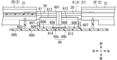
- the first joint 6 electrically connects the electric wires 20 of the two trolley wires 2 arranged in the left-right direction. More specifically, as shown in FIGS. 4 and 14, the first joint 6 electrically connects the electric wire 20 of the trolley wire 2D and the electric wire 20 of the trolley wire 2F. Furthermore, as shown in FIG. 4, the first joint 6 electrically connects the electric wire 20 of the trolley wire 2C and the electric wire 20 of the trolley wire 2E.
- the first joint 6 includes a body 60 and two terminal portions 61.
- the body 60 includes a first body 60a and a second body 60b disposed to the right of the first body 60a.
- the first body 60a and the second body 60b are made of, for example, synthetic resin.
- the first body 60a and the second body 60b have electrical insulation properties.
- the first body 60a and the second body 60b are fixed to the rail 3 using, for example, bolts and nuts.
- the trolley wires 2C and 2D are inserted into the first body 60a.
- Trolley wires 2E and 2F are inserted into the second body 60b.
- the shape of the first body 60a is a rectangular parallelepiped.
- the first body 60a has a space inside.
- the first body 60a includes a bottom wall 600, a first side wall 601, a second side wall 602, a third side wall 603, a partition wall 604, and a mounting piece 605.
- the shape of the bottom wall 600 is rectangular.
- the thickness direction of the bottom wall 600 is along the front-rear direction.
- the first body 60a further includes a plurality of (two in FIG. 14) positioning pieces 606.
- a plurality of positioning pieces 606 protrude forward from the bottom wall 600.
- the plurality of positioning pieces 606 position the terminal portion 61. That is, the terminal portion 61 is positioned at a position where it contacts the front surfaces of the plurality of positioning pieces 606.
- the first joint 6 has two terminal parts 61, and one terminal part 61 is positioned by two positioning pieces 606 of the first body 60a and two positioning pieces 606 of the second body 60b. has been done.
- the other terminal portion 61 is positioned by another two positioning pieces 606 of the first body 60a and another two positioning pieces 606 of the second body 60b.
- the first side wall 601 projects forward from the upper end of the bottom wall 600.
- the second side wall 602 projects forward from the lower end of the bottom wall 600.
- the third side wall 603 projects forward from the left end of the bottom wall 600.
- the first body 60a further includes a claw portion 6010.
- the claw portion 6010 protrudes from the first side wall 601.
- the claw portion 6010 hooks the trolley wire 2. More specifically, the claw portion 6010 hooks the covering member 21 of the trolley wire 2. Thereby, the claw portion 6010 restricts forward movement of the trolley wire 2.
- the second body 60b further includes a claw portion 6020.
- the claw portion 6020 protrudes from the second side wall 602.
- the claw portion 6020 hooks the trolley wire 2. More specifically, the claw portion 6020 hooks the covering member 21 of the trolley wire 2. Thereby, the claw portion 6020 restricts forward movement of the trolley wire 2.
- the partition wall 604 projects forward from a position between the first side wall 601 and the second side wall 602 of the bottom wall 600.
- the thickness direction of the partition wall 604 is along the up-down direction.
- Partition wall 604 partitions a space where one of the two trolley lines 2 is placed from a space where the other is placed.
- the first body 60a further includes a plurality of (six in FIG. 13) regulating walls 608.
- the plurality of regulating walls 608 protrude from the partition wall 604 in the vertical direction.
- the plurality of regulating walls 608 face the trolley wire 2 in the vertical direction.
- the plurality of regulating walls 608 regulate the movement of the trolley wire 2 in the direction (upward or downward) in which the pair of arms 611 and 612 sandwich the electric wire 20 .
- the movable range of the trolley wire 2C is limited to the range between the first side wall 601 and the three regulating walls 608 that protrude upward from the partition wall 604.
- the movable range of the trolley wire 2D is limited to the range between the second side wall 602 and the three regulating walls 608 that protrude downward from the partition wall 604.
- the mounting piece 605 protrudes from the bottom wall 600.
- the attachment piece 605 has a through portion 6050.
- the attachment piece 605 penetrates through the penetrating portion 6050 in the front-rear direction.
- the first body 60a is fixed to the rail 3 by, for example, passing a bolt through the through portion 6050 and a hole provided in the rail 3, and then passing the bolt through a nut on the rear surface of the rail 3.
- the first body 60a further includes two inner walls 607 and two (only one is shown in FIG. 14) retaining pieces 609.
- One inner wall 607 is provided on the upper and lower sides of the partition wall 604.
- a retaining piece 609 projects to the right from each inner wall 607 .
- the two retaining pieces 609 correspond one-to-one with the two terminal parts 61.
- Each retaining piece 609 is inserted into the corresponding terminal portion 61. This restricts forward movement of the terminal portion 61.
- the terminal portion 61 includes two pairs of arms 611 and 612 and a connecting portion 613.
- the terminal portion 61 is made of, for example, a metal plate.
- the shape of the connecting portion 613 is a rectangular plate.
- the thickness direction of the connecting portion 613 is along the front-back direction.
- a pair of arms 611 and 612 are provided to the left of the central portion of the connecting portion 613, and another pair of arms 611 and 612 are provided to the right of the central portion of the connecting portion 613.
- a connecting portion 613 connects the rear ends of each of the two pairs of arms 611 and 612.
- the arm 611 projects forward from the upper end of the connecting portion 613, and the arm 612 projects forward from the lower end of the connecting portion 613.
- the arm 611 projects forward from the upper end of the connecting portion 613, and the arm 612 projects forward from the lower end of the connecting portion 613.
- the terminal portion 61 has an opening OP1 between each pair of arms 611 and 612 on the front surface of the terminal portion 61.
- a connecting portion 613 is located behind the opening/closing opening OP1.
- the terminal portion 61 has spring properties. When no external force is applied to the pair of arms 611, 612, the opening/closing opening OP1 is closed due to the spring properties of the terminal portion 61. As described above, “the opening/closing port OP1 is closed” in the present disclosure refers to a state where the opening interval of the opening/closing port OP1 is relatively small.
- the pair of arms 611 and 612 are elastically deformed in the direction of opening the opening OP1.
- the protruding portion 202 is sandwiched between the pair of arms 611 and 612 due to the force of the pair of arms 611 and 612 attempting to elastically return.
- the contact portion 201 of the electric wire 20 is located in front of the pair of arms 611, 612 without being sandwiched between them.
- FIG. 7 shows a state in which the terminal portion 71 of the second joint 7 sandwiches the protruding portion 202 between the pair of arms 711 and 712, the terminal portion 61 also sandwiches the protruding portion 202 in the same manner.
- the terminal portion 61 has two pairs of arms.
- any pair of arms is composed of a first type arm portion 611 and a second type arm portion 612.
- One of the two pairs of arms of the terminal portion 61 is referred to as a pair of first arms 611 and 612, and the other is referred to as a pair of second arms 611 and 612.
- the pair of first arms 611 and 612 are electrically connected to the pair of second arms 611 and 612.
- the pair of first arms 611 and 612 sandwich the electric wire 20 of the first trolley wire among the plurality of trolley wires 2, and the pair of second arms 611 and 612 sandwich the electric wire 20 of the first trolley wire among the plurality of trolley wires 2.
- the electric wire 20 is sandwiched between the two wires.
- the first joint 6 electrically connects the electric wire 20 of the first trolley wire and the electric wire 20 of the second trolley wire.
- the terminal portion 61 further includes a convex portion 614.
- the convex portion 614 protrudes from the connecting portion 613. More specifically, the convex portion 614 protrudes from the rear surface of the connecting portion 613.
- the convex portion 614 is inserted between the positioning piece 606 of the first body 60a and the positioning piece 606 of the second body 60b. Thereby, the terminal portion 61 is positioned. Further, the terminal portion 61 is reinforced by providing the convex portion 614, and the possibility that the terminal portion 61 is bent by the force of inserting and removing the power line C1 into and from the terminal portion 61 is reduced. Further, the terminal portion 61 is arranged between the inner wall 607 of the first body 60a and the inner wall 607 of the second body 60b.
- the second joint 7 has the function of electrically connecting the electric wire 20 to the power line C1. Furthermore, like the first joint 6, the second joint 7 has a function of electrically connecting the electric wires 20 of the two trolley wires 2 arranged in the left-right direction.
- the second joint 7 electrically connects the electric wire 20 of the trolley wire 2A and the electric wire 20 of the trolley wire 2C. Furthermore, the second joint 7 electrically connects the electric wire 20 of the trolley wire 2B and the electric wire 20 of the trolley wire 2D.
- the second joint 7 includes a body 70, two terminal portions 71, an insulating cover 72, and a fastening member 73.
- the fastening member 73 is, for example, a screw or a bolt.
- the body 70 is made of, for example, synthetic resin.
- the body 70 has electrical insulation properties.
- the body 70 is fixed to the rail 3 using, for example, bolts 74 and nuts 75.
- the shape of the body 70 is a rectangular parallelepiped.
- the body 70 has a space inside.
- the body 70 includes a bottom wall 700, a first side wall 701, a second side wall 702, a plurality of (two in FIG. 15) mounting pieces 703, a first partition wall 704, a second partition wall 705, and a plurality of mounting pieces 703. , a plurality of (twelve in FIG. 15) regulating walls 708, a plurality (two in FIG. 15) of retaining pieces 709, a plurality of (two in FIG. 15) claw portions 7010, and a plurality of (two in FIG. 15) retaining pieces 709. (two in FIG. 15) claw portions 7020.
- the first partition wall 704 projects forward from a position between the first side wall 701 and the second side wall 702 of the bottom wall 700.
- the thickness direction of the first partition wall 704 is along the up-down direction.
- the first partition wall 704 partitions a space where one of the two power lines C1 and the trolley wire 2A are arranged from a space where the other of the two power lines C1 and the trolley line 2B are arranged.
- the first partition wall 704 has a boss portion 707.
- the insulating cover 72 fits into the first partition wall 704.
- the insulating cover 72 also has a hole 720.
- the fastening member 73 is inserted into the boss portion 707 through the hole 720. Thereby, the insulating cover 72 is fastened to the body 70.
- the insulating cover 72 has the same configuration as the insulating cover 42 of the first end member 4, so a detailed explanation will be omitted.
- Two electric wires 20 are arranged in front of the insulating cover 72.
- Two power lines C1 are arranged behind the insulating cover 72.
- the terminal section 71 includes two pairs of arms 711 and 712, a connecting section 713, and a power terminal 714.
- the terminal portion 71 is made of, for example, a metal plate.
- the two pairs of arms 711, 712 of the terminal part 71 and the connecting part 713 have the same configuration as the two pairs of arms 611, 612 and the connecting part 613 of the terminal part 61 of the first joint 6, so the explanation will be omitted. Omitted.
- the power terminal 714 protrudes from the connecting portion 713 in the left-right direction.
- the power line C1 is attached to and electrically connected to the power terminal 714 using a rivet R1 or the like.
- the mobile device 9 includes a device main body and a current collector 90.
- the device main body includes an electric device such as an electric motor.
- the main body of the device receives power from the electric wire 20 via the current collector 90 .
- the current collector 90 includes a base block 91, a rotating seat 92, a swing arm 93, a rotating joint 94, a collecting arm 95, a plurality of (two in FIG. 10) current collector holders 96, and a plurality of current collectors. 97 and a cable 98.
- the base block 91 is fixed to the main body of the device.
- the rotating seat 92 is connected to the base block 91.
- a first end of the swing arm 93 is attached to the rotating seat 92, and a second end is attached to the rotating joint 94.
- the swing arm 93 is rotatable with respect to the rotating seat 92.
- the collective arm 95 is attached to the rotary joint 94. Collective arm 95 is rotatable relative to rotary joint 94 .
- a plurality of current collector holders 96 are attached to the collecting arm 95 .
- a plurality of current collectors 97 are attached to the plurality of current collector holders 96 .
- the plurality of current collectors 97 are electrically connected to the main body of the apparatus via cables 98.
- the plurality of current collectors 97 contact the electric wires 20 fixed to the rail 3. Thereby, the plurality of current collectors 97 and the electric wires 20 are electrically connected. The plurality of current collectors 97 slide on the surface of the electric wire 20.
- At least one of the plurality of connection members (the first termination member 4 and the second joint 7) has the power supply terminals 414, 714 to which the power line C1 is electrically connected, and is connected to the external power supply. Power supplied via the power line C1 is supplied to the mobile device 9 via the electric wire 20.
- At least one of the plurality of connection members is the first termination member 4 having a terminal portion 41 that connects to the end (right end or left end) of the electric wire 20.
- the first termination member 4 has a power terminal 414 to which the power line C1 is electrically connected, and supplies power supplied from an external power source via the power line C1 to the mobile device 9 via the electric wire 20.
- the worker first fixes the plurality of supporters S1 to each of the plurality of rails 3. That is, as shown in FIG. 1, the worker fixes the plurality of supporters S1 to the front surface of the bottom wall 31 of the rail 3 so that the plurality of supporters S1 are lined up in the left-right direction.
- the worker attaches the supporter S1 to the rail 3 by, for example, passing a bolt through a penetration part provided in the supporter S1 and a hole provided in the bottom wall 31, and then passing the bolt through a nut on the rear surface of the rail 3. Fixed to.
- the worker fixes the rail 3 to, for example, the building frame.
- a worker fixes the rail 3 to the frame using, for example, bolts and nuts.
- the operator connects the two power lines C1 to the two power terminals 414 (see FIG. 11) of the first termination member 4 among the plurality of supporters S1. Further, the operator covers the two power lines C1 with the insulating cover 42 and attaches the insulating cover 42 to the body 40 using the fastening member 43. The operator also connects the two power lines C1 to the two power terminals 714 (see FIG. 15) of the second joint 7. Further, the operator covers the two power lines C1 with the insulating cover 72 and attaches the insulating cover 72 to the body 70 using the fastening member 73.
- the operator processes the covering member 21 of each of the plurality of trolley wires 2 as necessary. More specifically, the operator uses a tool to peel off a portion of the covering member 21.
- the operator strips off the covering member 21 at the tip portion (first section) of the trolley wire 2 to completely expose the electric wire 20.
- the first section is a section including a portion of the trolley wire 2 that is sandwiched between the terminal portions 41.
- the operator cuts the plurality of rear ribs 212 of the covering member 21 in the second section adjacent to the first section of the electric wire 20, for example, as shown in FIG.
- the second section is a section including a portion of the electric wire 20 that is inserted into the body 40. Further, the second section is a section including a portion of the electric wire 20 that faces the insulating cover 42.
- the electricity between the electric wire 20, the fastening member 43, and the power line C1 is lower than when the electric wire 20 in the second section is completely exposed. Higher insulation.
- the operator moves the plurality of trolley wires 2 from the front of the plurality of supports S1 so as to press them against the plurality of supports S1. Thereby, as shown in FIG. 2, the plurality of trolley wires 2 are inserted into each of the plurality of supporters S1.
- the two vertically connected trolley wires 2 (for example, trolley wires 2A and 2B) are inserted into each of the plurality of supporters S1 at once.
- the protruding portion 202 of the electric wire 20 is sandwiched between the terminal portions 71, as shown in FIG. Further, when the trolley wire 2 is inserted into the first terminal member 4, the protruding portion 202 of the electric wire 20 is sandwiched between the terminal portions 41, as shown in FIG. Further, when the trolley wire 2 is inserted into the first joint 6, the protruding portion 202 of the electric wire 20 is sandwiched between the terminal portions 61.
- the pair of arms 411, 412 sandwich the electric wire 20 inserted into the opening/closing opening OP1 from the front of the opening/closing opening OP1 along the longitudinal direction of the electric wire 20. More specifically, the pair of arms 411, 412 (or 611, 612, or 711, 712) connect the electric wire 20 inserted into the opening/closing opening OP1 from the front of the opening/closing opening OP1 with the longitudinal direction of the electric wire 20 oriented in the left-right direction. sandwich.
- FIG. 4 shows the power supply device 1 in a state where construction has been completed.
- the first terminating member 4 is a connecting member having a terminal portion 41 electrically connected to the electric wire 20, and the terminal portion 41 of the first terminating member 4 is a connecting member having a terminal portion 41 that is electrically connected to the electric wire 20.
- a pair of arms 411 and 412 sandwiching the protrusion 202 therebetween.
- the first joint 6 is a connecting member having a terminal portion 61 that is electrically connected to the electric wire 20, and the terminal portion 61 of the first joint 6 is a protruding portion of the electric wire 20. It includes a pair of arms 611 and 612 that sandwich 202 between them.
- the second joint 7 is a connecting member having a terminal portion 71 that is electrically connected to the electric wire 20, and the terminal portion 71 of the second joint 7 is a protruding portion of the electric wire 20. It includes a pair of arms 711 and 712 that sandwich 202 between them.
- the covering member 21 exposes the electric wire 20 in a part (first section) extending from the end (left end or right end) of the electric wire 20, and the pair of arms 411, 412 of the terminal part 41,
- the electric wire 20 in the above-mentioned part of the section is sandwiched.
- the pair of arms 711 and 712 of the terminal portion 71 sandwich the electric wire 20 in the above-mentioned part of the section.
- the pair of arms 611 and 612 of the terminal portion 61 sandwich the electric wire 20 in the above-mentioned partial section.
- the first terminal member 4 among the plurality of connecting members includes an electrically insulating insulating cover 42 disposed between the power line C1 and the electric wire 20, a fastening member 43 that fastens the insulating cover 42 to the body 40, has.
- the above-mentioned partial section (first section) in which the electric wire 20 is exposed is a section different from the section (second section) in which the fastening member 43 is provided. Thereby, electrical insulation between the fastening member 43 and the electric wire 20 can be ensured.
- the second joint 7 among the plurality of connecting members includes an electrically insulating cover 72 arranged between the power line C1 and the electric wire 20, a fastening member 73 that fastens the insulating cover 72 to the body 70, has.
- the above-mentioned partial section (first section) in which the electric wire 20 is exposed is a section different from the section (second section) in which the fastening member 73 is provided.
- the operator can simply move the trolley wire 2 from the front to the rear and insert it into the terminal section 41 (or 61 or 71), and the electric wire 20 and terminal section 41 (or 61 or 71) ) connection is completed.
- the operation of the trolley wire 2 can be as simple as moving the trolley wire 2 backward.
- the attachment of the trolley wire 2 is completed with one touch. Therefore, even if the power supply device 1 is installed in a narrow place, construction is easy.
- the trolley wire 2 can be manufactured from a material that is difficult to bend. Moreover, the trolley wire 2 can be formed into a shape that is difficult to bend.
- the covering member 21 of the trolley wire 2 has a plurality of rear ribs 212. Further, the covering member 21 has a plurality of front ribs 213. Thereby, the trolley wire 2 is formed into a relatively long shape in the front-rear direction. Therefore, the possibility that the trolley wire 2 is bent about the axis along the vertical direction is reduced.
- the electric wire 20 of the trolley wire 2 has a contact portion 201 having a length in the vertical direction, and a protrusion portion 202 that protrudes rearward from the contact portion 201.
- the cross-sectional shape of the electric wire 20 is Y-shaped. Due to this shape of the electric wire 20 and the fact that the covering member 21 has the rear rib 212 and the front rib 213, the section modulus of the trolley wire 2 becomes relatively large, so that the trolley wire 2 is difficult to bend.
- the installation interval of the supporters S1 can be made relatively long. That is, the number of supporters S1 included in the power supply device 1 can be reduced.
- the trolley wire 2 may be bent as the moving device 9 moves while pushing the electric wire 20 backward by the current collector 97. Then, the electric wire 20 may separate from the current collector 97, and the electrical connection between the current collector 97 and the electric wire 20 may be broken. On the other hand, since the trolley wire 2 is formed to be difficult to bend as described above, the electrical connection between the current collector 97 and the electric wire 20 is difficult to be broken.
- Modification 1 the power supply device 1 according to Modification Example 1 will be described using FIG. 16. Components similar to those in the embodiment will be given the same reference numerals and descriptions will be omitted.
- the power supply device 1 of Modification 1 includes a hanger 5A instead of the hanger 5 (see FIG. 12).
- the hanger 5A has a plurality of (two in FIG. 16) insertion portions 55.
- the two insertion portions 55 protrude forward from the bottom wall 50.
- the two insertion portions 55 correspond one-to-one to the two trolley wires 2 inserted into the hanger 5A.
- Each insertion portion 55 is inserted between two rear ribs 212 of the corresponding trolley wire 2. Thereby, the trolley wire 2 is fixed more firmly, and the possibility that the trolley wire 2 is bent is reduced.
- At least one of the first end member 4, second end member 8, first joint 6, and second joint 7 may have the same configuration as the insertion portion 55. That is, at least one supporter S1 among the plurality of supporters S1 may have the insertion portion 55 inserted between two adjacent rear ribs 212 among the plurality of rear ribs 212.
- Modification 2 The power supply device 1 according to Modification Example 2 will be described below with reference to FIG. 17. Components similar to those in the embodiment will be given the same reference numerals and descriptions will be omitted.
- the power supply device 1 of this modification 2 differs from the embodiment with respect to the shape of the covering member 21.
- the covering member 21 includes a covering main body 211 and a plurality of (two in FIG. 17) front ribs 213.
- the covering body 211 further includes an extension portion 2113 extending rearward from the rear side portion 2112.
- the width of the extension portion 2113 is equal to the width of the rear side portion 2112. That is, the extension part 2113 is provided by extending the rear side part 2112 rearward.
- a cavity may exist inside the extension portion 2113.
- the extension portion 2113 is provided, so that the trolley wire 2 is relatively long in the front-rear direction. Therefore, the possibility that the trolley wire 2 is bent about the axis along the vertical direction is reduced.
- Modification 3 The power supply device 1 according to Modification Example 3 will be described below with reference to FIG. 18. Components similar to those in the embodiment will be given the same reference numerals and descriptions will be omitted.
- the power supply device 1 of Modification 3 differs from the embodiment in the shape of the electric wire 20 and the shape of the covering member 21.
- the electric wire 20 is made of a flexible member. In a cross section perpendicular to the left-right direction, the electric wire 20 has a string-like shape. The electric wire 20 is formed to have a U-shaped cross section with both ends of the string facing each other.
- the covering member 21 includes a covering main body 211, a plurality of (two in FIG. 18) rear ribs 212a, 212b, and a front rib 213a. Further, the two covering members 21 are connected via a first connecting portion 22 and a second connecting portion 23.
- the first connection section 22 has a similar configuration to the connection section 22 described above.
- the rear rib 212a protrudes rearward from the rear side portion 2112 of the covering main body 211.
- the rear rib 212b is provided with an interval in the vertical direction with respect to the rear rib 212a.
- the rear ribs 212b of each of the two trolley lines 2 face each other in the vertical direction.
- Each rear rib 212b includes a first protruding piece 2121 and a second protruding piece 2122.
- the first projecting piece 2121 projects from the rear side portion 2112 toward the other trolley wire 2 .
- the second protruding piece 2122 protrudes rearward from the tip of the first protruding piece 2121.
- the second connecting portion 23 connects the covering bodies 211 of the two covering members 21.
- the second connecting portion 23 is provided forward of the covering body 211.
- a front rib 213b projects forward from the second connecting portion 23.
- the trolley wire 2 is relatively long in the front-rear direction due to the provision of the rear rib 212 and the front rib 213. Therefore, the possibility that the trolley wire 2 is bent about the axis along the vertical direction is reduced.
- the trolley wire 2 of Modification 3 is different from the embodiment in the configurations of the electric wire 20, the rear rib 212, and the front rib 213.
- the configuration of one or two of the electric wire 20, the rear rib 212, and the front rib 213 may be consistent with the embodiment.
- Modification 4 a power supply device 1 according to modification 4 will be described using FIG. 19. Components similar to those in the embodiment will be given the same reference numerals and descriptions will be omitted.
- FIG. 19 is a cross-sectional view of the trolley wire 2 in the first section extending from the end of the electric wire 20.
- the covering member 21 was completely removed in the first section.
- Modification 4 only a portion of the covering member 21 is removed in the first section.
- the covering member 21 includes a front side part 2111 and a rear side part 2112.
- the rear side part 2112 extends from the back of the front side part 2111.
- the first section is a part of the section extending from the end of the electric wire 20, and is a section where the electric wire 20 is sandwiched between the pair of arms 411 and 412 of the terminal section 41.
- the rear side portion 2112 exists in a section different from the first section.
- the rear portion 2112 is in a second section adjacent to the first section.
- the rear side portion 2112 exists in all sections except the first section.
- a part of the electric wire 20 is covered by the front side part 2111, and the rear surface of the electric wire 20 is exposed. More specifically, as shown in FIG. 19, in the first section, the rear surface of the contact portion 201 of the electric wire 20 and the protruding portion 202 are exposed. Note that the expression that the rear surface of the electric wire 20 is exposed means that at least the rear end of the protruding portion 202 is exposed.
- the power supply device 1 is not limited to a contact-type power supply device that supplies power to the mobile device 9 by contacting the mobile device 9, but may be a non-contact power supply device that supplies power to the mobile device 9 without contacting the mobile device 9. You can.
- the work of connecting the electric wire 20 to the terminal portions 41, 61, and 71 may be performed by a machine instead of manually. Further, the work may be performed not at the facility where the power supply device 1 is installed, but at a factory where the power supply device 1 is manufactured.
- the number of trolley wires 2 included in the power supply device 1 may be one, or two or more.
- the number of rails 3 may be one, or two or more.
- the rail 3 may be a component of the power supply device 1.
- the mobile device 9 moves along the rail 3.
- This rail 3 and the rail to which the trolley wire 2 is fixed may be separate members.
- the number of supporters S1 included in the power supply device 1 may be two, or may be three or more.
- the number of each component of the power supply device 1 is not limited to the number shown in the embodiment, and can be changed as appropriate.
- the first terminal member 4 may have only one terminal portion 41, or may have three or more terminal portions 41.
- the covering member 21 may have only one rear rib 212, or may have three or more rear ribs 212.
- the covering member 21 may have only one front rib 213, or may have three or more front ribs 213.
- the body 60 of the first joint 6 may be formed from a single member like the body 70 of the second joint 7.
- the body 70 of the second joint 7 may have a first body and a second body like the body 60 of the first joint 6.
- the covering member 21 of the trolley wire 2 is stripped off in the first section including the end portion and connected to the terminal portions 41, 61, 71, the covering member 21 is stripped off at a portion away from the end portion.
- the terminal portions 41, 61, and 71 may be connected to each other.
- the covering member 21 of the trolley wire 2 is not limited to being partially peeled off to expose the electric wire 20 at the construction site of the power supply device 1 or the like.
- the covering member 21 may be manufactured in such a shape that the electric wire 20 is exposed in advance in a part of the section (first section) between both ends of the electric wire 20 in the left-right direction.
- At least one supporter S1 among the plurality of supporters S1 may be arranged at a location other than the front surface of the rail 3.
- at least one supporter S1 may be arranged on the first side wall 32 or the second side wall 33 of the rail 3.
- the configuration disclosed in the embodiment or the modified example regarding some of the supporters S1 among the plurality of supporters S1 can be applied to other supporters S1 as appropriate.
- the first end member 4 may have a configuration similar to the attachment piece 54 of the hanger 5 (see FIG. 12).
- the terminal portion 71 of the second joint 7 may have the same configuration as the convex portion 614 (see FIG. 14) of the terminal portion 61 of the first joint 6.
- the pair of arms 411 and 412 of the terminal portion 41 is not limited to the configuration in which only the protruding portion 202 of the electric wire 20 is sandwiched.
- the pair of arms 411 and 412 may sandwich the entire electric wire 20. The same applies to the other terminal portions 61 and 71.
- the electric wire 20 may have the contact portion 201 but may not have the protrusion portion 202. Moreover, the electric wire 20 may have a circular cross-sectional shape, for example.
- Three or more trolley wires 2 may be connected to each other at the covering member 21.
- the above-mentioned three or more trolley wires 2 may be lined up in the vertical direction.
- At least a portion of the front rib 213 of the covering member 21 may be stripped off in a part of the section between both ends of the electric wire 20 in the left-right direction.
- connection members the first and second joints 6, 7 or the first end member 4
- the trolley wire 2 of the power supply device 1 may be provided alone.
- a power supply device (1) supplies power to a mobile device (9).
- the mobile device (9) is movable along the rail (3).
- the power supply device (1) includes a trolley wire (2) and a connection member.
- the trolley wire (2) has an electric wire (20).
- the electric wire (20) is used as a power supply path to the mobile device (9) by electrically connecting it to the mobile device (9).
- the connecting member is a member for arranging the trolley wire (2) along the rail (3).
- the connection member includes a terminal portion (41; 61; 71) and a body (40; 60; 70).
- the terminal portion (41; 61; 71) is electrically connected to the electric wire (20).
- the body (40; 60; 70) holds the terminal portion (41; 61; 71).
- the terminal portion (41; 61; 71) has a pair of arms (411, 412; 611, 612; 711, 712) and an opening/closing opening (OP1).
- the opening/closing opening (OP1) is provided between a pair of arms (411, 412; 611, 612; 711, 712), and is opened by an external force applied between the pair of arms (411, 412; 611, 612; 711, 712). Vary the spacing.
- a pair of arms (411, 412; 611, 612; 711, 712) change the opening interval of the opening/closing opening (OP1) for the electric wire (20) inserted into the opening/closing opening (OP1) from the front of the opening/closing opening (OP1). Let me pinch it.
- a worker or the like inserts the electric wire (20) of the trolley wire (2) into the opening/closing opening (OP1) from the front, and then inserts the electric wire (20) into the terminal portion (41; 61; 71).
- the electric wire (20) can be electrically connected to the terminal portion (41; 61; 71) by sandwiching it between the pair of arms (411, 412; 611, 612; 711, 712). In this way, the work of installing the trolley wire (2) can be simplified.
- the electric wire (20) includes a contact portion (201) and a protrusion portion (202).
- the contact portion (201) has a front surface (2010) exposed to the outside.
- the protruding portion (202) protrudes from the rear surface of the contact portion (201).
- the pair of arms (411, 412; 611, 612; 711, 712) sandwich the protrusion (202) inserted into the opening/closing opening (OP1).
- the pair of arms (411, 412; 611, 612; 611, 612; 711, 712) can be made smaller. Therefore, it becomes easier for workers and the like to install the trolley wire (2).
- the trolley wire (2) further includes a covering member (21).
- the covering member (21) has electrical insulation properties.
- the covering member (21) covers a part of the electric wire (20).
- the covering member (21) exposes the electric wire (20) in a part of the section extending from the end of the electric wire (20).
- the pair of arms (411, 412; 611, 612; 711, 712) sandwich the electric wire (20) in the above-mentioned partial section.
- the electrical insulation of the electric wire (20) can be improved.
- the power feeding device (1) according to the fourth aspect includes a plurality of trolley wires (2) including the above-mentioned trolley wire (2) in the third aspect. Two of the plurality of trolley lines (2) are arranged in parallel. The two trolley wires (2) are connected to each other at the covering member (21).
- a worker etc. can perform the work of electrically connecting the electric wire (20) to the terminal part (41; 61; 71) for two electric wires (20) at once. can.
- connection member further includes a power terminal (414; 714) to which the power line (C1) is electrically connected.
- the connection member supplies power supplied from an external power source via the power line (C1) to the mobile device (9) via the electric wire (20).
- the connection member further includes an insulating cover (42; 72) and a fastening member (43; 73).
- the insulating cover (42; 72) is arranged between the power line (C1) and the electric wire (20).
- the insulating cover (42; 72) has electrical insulation properties.
- the fastening member (43; 73) fastens the insulating cover (42; 72) to the body (40; 70).
- the above-mentioned part of the section where the electric wire (20) is exposed is a section different from the section where the fastening member (43; 73) is provided.
- the covering member (21) has a front side part (2111), a rear side part (2112), including.
- the rear side portion (2112) exists in a section different from the above-mentioned partial section of the electric wire (20).
- the rear side (2112) extends from behind the front side (2111). In the above-mentioned part of the section, a part of the electric wire (20) is covered by the front side part (2111), and the rear surface of the electric wire (20) is exposed.
- the insulation distance between the electric wire (20) and the surrounding structure can be extended compared to the case where the front side part (2111) is not provided in the above part of the section.
- the connecting member has a terminal portion having a terminal portion (41) connected to an end portion of the electric wire (20).
- the termination member (4) further includes a power terminal (414) to which the power line (C1) is electrically connected. The termination member (4) supplies power supplied from an external power source via the power line (C1) to the mobile device (9) via the electric wire (20).
- the termination member (4) can have a function of receiving power from an external power source.
- the power feeding device (1) in any one of the first to seventh aspects, includes a plurality of trolley wires (2) including the above-mentioned trolley wire (2).
- the terminal portion (61; 71) has two pairs of arms (611, 612; 711, 712). Of the two pairs of arms (611, 612; 711, 712), one pair of first arms (611, 612; 711, 712) connects to the other pair of second arms (611, 612; 711, 712). electrically connected.
- the pair of first arms (611, 612; 711, 712) sandwich the electric wire (20) of the first trolley wire among the plurality of trolley wires (2).
- the pair of second arms (611, 612; 711, 712) sandwich the electric wire (20) of the second trolley wire among the plurality of trolley wires (2).
- the two electric wires (20) can be electrically connected via the terminal portions (61; 71) to extend the power supply path.
- the body (40; 60; 70) has a regulating wall (408; 608; 708).
- the regulating wall (408; 608; 708) regulates the movement of the trolley wire (2) in the direction in which the pair of arms (411, 412; 611, 612; 711, 712) sandwich the electric wire (20).
- the body (40; 60; 70) has the claw portion (4010, 4020; 6010, 6020; , 7020).
- the claw portions (4010, 4020; 6010, 6020; 7010, 7020) hook the trolley wire (2) to restrict forward movement of the trolley wire (2).
- the electric wire (20) sandwiched between the pair of arms (411, 412; 611, 612; 711, 712) comes off from the pair of arms (411, 412; 611, 612; 711, 712). The possibility is reduced.
- the body (40; 60; 70) has a plurality of positioning pieces (406; 606; 706).
- the terminal portion (41; 61; 71) further includes a connecting portion (413; 613; 713) and a convex portion (614).
- the connecting portion (413; 613; 713) connects the rear ends of each of the pair of arms (411, 412; 611, 612; 711, 712).
- the convex portion (614) protrudes from the connecting portion (413; 613; 713) and is inserted between the plurality of positioning pieces (406; 606; 706).
- the terminal portion (41; 61; 71) can be positioned between the plurality of positioning pieces (406; 606; 706).
- the configurations other than the first aspect are not essential to the power supply device (1) and can be omitted as appropriate.
- connection member according to the twelfth aspect is used in the power supply device (1) according to any one of the first to eleventh aspects.
- the construction method according to the thirteenth aspect is a construction method of a power supply device (1) that supplies power to a mobile device (9).
- the mobile device (9) is movable along the rail (3).
- the power supply device (1) includes a trolley wire (2) and a connection member.
- the trolley wire (2) has an electric wire (20).
- the electric wire (20) is used as a power supply path to the mobile device (9) by electrically connecting it to the mobile device (9).
- the connecting member is a member for arranging the trolley wire (2) along the rail (3).
- the connection member includes a terminal portion (41; 61; 71) and a body (40; 60; 70).
- the terminal portion (41; 61; 71) is electrically connected to the electric wire (20).
- the body (40; 60; 70) holds the terminal portion (41; 61; 71).
- the terminal portion (41; 61; 71) has a pair of arms (411, 412; 611, 612; 711, 712) and an opening/closing opening (OP1).
- the opening/closing opening (OP1) is provided between a pair of arms (411, 412; 611, 612; 711, 712), and is opened by an external force applied between the pair of arms (411, 412; 611, 612; 711, 712). Vary the spacing.
- the construction method includes a first step and a second step. In the first step, the body (40; 60; 70) of the connecting member is attached to the rail (3).
- the electric wire (20) is inserted into the opening/closing opening (OP1) from the front of the opening/closing opening (OP1), the opening interval of the opening/closing opening (OP1) is changed, and the pair of arms (411 , 412; 611, 612; 711, 712) to sandwich the electric wire (20).
- a worker or the like inserts the electric wire (20) of the trolley wire (2) into the opening/closing opening (OP1) from the front, and then inserts the electric wire (20) into the terminal portion (41; 61; 71).
- the electric wire (20) can be electrically connected to the terminal portion (41; 61; 71) by sandwiching it between the pair of arms (411, 412; 611, 612; 711, 712). In this way, the work of installing the trolley wire (2) can be simplified.
Landscapes
- Engineering & Computer Science (AREA)
- Mechanical Engineering (AREA)
- Manufacturing & Machinery (AREA)
- Current-Collector Devices For Electrically Propelled Vehicles (AREA)
- Details Of Connecting Devices For Male And Female Coupling (AREA)
Abstract
The purpose of the present disclosure is to simplify the work of installing a trolley wire. A power feeding device comprises a trolley wire (2) and a connection member. The trolley wire (2) includes an electric wire (20). The connection member is a member for placing the trolley wire (2) along a rail (3). The connection member includes a terminal portion (71) and a body (70). The terminal portion (71) is electrically connected to the electric wire (20). The body (70) holds the terminal portion (71). The terminal portion (71) includes a pair of arms and an open/close opening (OP1) provided between the pair of arms. As the electric wire (20) is inserted into the open/close opening (OP1) from the front thereof, the pair of arms change the opening interval of the open/close opening (OP1) and pinch the electric wire (20).
Description
本開示は一般に給電装置、接続部材及び施工方法に関し、より詳細には、トロリー線を有する給電装置、この給電装置に用いられる接続部材、及びこの給電装置の施工方法に関する。
The present disclosure generally relates to a power supply device, a connection member, and a construction method, and more particularly relates to a power supply device having a trolley wire, a connection member used in this power supply device, and a construction method of this power supply device.
特許文献1に記載の絶縁トロリーは、引締め装置と、第1接続ブロックと、第2接続ブロックと、を備える。引締め装置は、第1絶縁トロリー線(トロリー線)の第1端部と、第2絶縁トロリー線(トロリー線)の第2端部と、を保持する。第1接続ブロックは、第1絶縁トロリー線の第1端部とは反対の第3端部を保持する。第2接続ブロックは、第2絶縁トロリー線の第2端部とは反対の第4端部を保持する。
The insulated trolley described in Patent Document 1 includes a tightening device, a first connection block, and a second connection block. The tightening device holds a first end of a first insulated trolley wire and a second end of a second insulated trolley wire. The first connection block holds a third end opposite the first end of the first insulated trolley wire. The second connection block holds a fourth end opposite the second end of the second insulated trolley wire.
本開示は、トロリー線を設置する作業を簡素化することができる給電装置、接続部材及び施工方法を提供することを目的とする。
An object of the present disclosure is to provide a power supply device, a connection member, and a construction method that can simplify the work of installing a trolley wire.
本開示の一態様に係る給電装置は、移動機器へ電力を供給する。前記移動機器は、レールに沿って移動可能である。前記給電装置は、トロリー線と、接続部材と、を備える。前記トロリー線は、電線を有する。前記電線は、前記移動機器に電気的に接続することにより前記移動機器への電力の供給路として使用される。前記接続部材は、前記トロリー線を前記レールに沿って配置するための部材である。前記接続部材は、端子部と、ボディと、を有する。前記端子部は、前記電線に電気的に接続される。前記ボディは、前記端子部を保持する。前記端子部は、一対のアームと、開閉口と、を有する。前記開閉口は、前記一対のアーム間に設けられ、前記一対のアーム間に加わる外力により開口間隔を変化させる。前記一対のアームは、前記開閉口の前方から前記開閉口に挿入された前記電線を前記開閉口の開口間隔を変化させて挟む。
A power supply device according to one aspect of the present disclosure supplies power to a mobile device. The mobile device is movable along a rail. The power supply device includes a trolley wire and a connection member. The trolley wire includes an electric wire. The electric wire is used as a power supply path to the mobile device by being electrically connected to the mobile device. The connecting member is a member for arranging the trolley wire along the rail. The connection member includes a terminal portion and a body. The terminal portion is electrically connected to the electric wire. The body holds the terminal portion. The terminal portion has a pair of arms and an opening/closing opening. The opening/closing opening is provided between the pair of arms, and the opening interval is changed by an external force applied between the pair of arms. The pair of arms sandwich the electric wire inserted into the opening/closing opening from the front of the opening/closing opening while changing the opening interval of the opening/closing opening.
本開示の一態様に係る接続部材は、前記給電装置に用いられる。
A connection member according to one aspect of the present disclosure is used in the power supply device.
本開示の一態様に係る施工方法は、移動機器へ電力を供給する給電装置の施工方法である。前記移動機器は、レールに沿って移動可能である。前記給電装置は、トロリー線と、接続部材と、を備える。前記トロリー線は、電線を有する。前記電線は、前記移動機器に電気的に接続することにより前記移動機器への電力の供給路として使用される。前記接続部材は、前記トロリー線を前記レールに沿って配置するための部材である。前記接続部材は、端子部と、ボディと、を有する。前記端子部は、前記電線に電気的に接続される。前記ボディは、前記端子部を保持する。前記端子部は、一対のアームと、開閉口と、を有する。前記開閉口は、前記一対のアーム間に設けられ、前記一対のアーム間に加わる外力により開口間隔を変化させる。前記施工方法は、第1ステップと、第2ステップと、を有する。前記第1ステップでは、前記接続部材の前記ボディを前記レールに取り付ける。前記第2ステップでは、前記第1ステップの後に、前記開閉口の前方から前記電線を前記開閉口に挿入し、前記開閉口の開口間隔を変化させて前記一対のアームにより前記電線を挟む。
A construction method according to one aspect of the present disclosure is a construction method of a power supply device that supplies power to a mobile device. The mobile device is movable along a rail. The power supply device includes a trolley wire and a connection member. The trolley wire includes an electric wire. The electric wire is used as a power supply path to the mobile device by being electrically connected to the mobile device. The connecting member is a member for arranging the trolley wire along the rail. The connection member includes a terminal portion and a body. The terminal portion is electrically connected to the electric wire. The body holds the terminal portion. The terminal portion has a pair of arms and an opening/closing opening. The opening/closing opening is provided between the pair of arms, and the opening interval is changed by an external force applied between the pair of arms. The construction method includes a first step and a second step. In the first step, the body of the connecting member is attached to the rail. In the second step, after the first step, the electric wire is inserted into the opening from the front of the opening and closing, and the electric wire is sandwiched between the pair of arms while changing the opening interval of the opening and closing.
(実施形態)
以下、実施形態に係る給電装置1について、図面を用いて説明する。ただし、下記の実施形態は、本開示の様々な実施形態の1つに過ぎない。下記の実施形態は、本開示の目的を達成できれば、設計等に応じて種々の変更が可能である。また、下記の実施形態において説明する各図は、模式的な図であり、図中の各構成要素の大きさ及び厚さそれぞれの比が必ずしも実際の寸法比を反映しているとは限らない。 (Embodiment)
Hereinafter, apower supply device 1 according to an embodiment will be described using the drawings. However, the embodiment described below is only one of various embodiments of the present disclosure. The embodiments described below can be modified in various ways depending on the design, etc., as long as the objective of the present disclosure can be achieved. In addition, each figure described in the following embodiments is a schematic diagram, and the ratio of the size and thickness of each component in the figure does not necessarily reflect the actual size ratio. .
以下、実施形態に係る給電装置1について、図面を用いて説明する。ただし、下記の実施形態は、本開示の様々な実施形態の1つに過ぎない。下記の実施形態は、本開示の目的を達成できれば、設計等に応じて種々の変更が可能である。また、下記の実施形態において説明する各図は、模式的な図であり、図中の各構成要素の大きさ及び厚さそれぞれの比が必ずしも実際の寸法比を反映しているとは限らない。 (Embodiment)
Hereinafter, a
(概要)
図1に示すように、本実施形態の給電装置1は、移動機器9(図10参照)へ電力を供給する。移動機器9は、レール3に沿って移動可能である。給電装置1は、トロリー線2と、接続部材と、を備える。トロリー線2は、電線20を有する。電線20は、移動機器9に電気的に接続することにより移動機器9への電力の供給路として使用される。接続部材は、トロリー線2をレール3に沿って配置するための部材である。ここでは、接続部材の一例である第2ジョイント7(図6、図15参照)に着目して説明する。接続部材(第2ジョイント7)は、端子部71と、ボディ70と、を有する。端子部71は、電線20に電気的に接続される。ボディ70は、端子部71を保持する。端子部71は、一対のアーム711、712と、一対のアーム711、712間に設けられた開閉口OP1と、を有する。開閉口OP1は、一対のアーム711、712間に加わる外力により開口間隔を変化させる。一対のアーム711、712は、開閉口OP1の前方から開閉口OP1に挿入された電線20を開閉口OP1の開口間隔を変化させて挟む(図2、図6、図7、図13、図15参照)。 (overview)
As shown in FIG. 1, thepower supply device 1 of this embodiment supplies power to a mobile device 9 (see FIG. 10). The mobile device 9 is movable along the rail 3. The power supply device 1 includes a trolley wire 2 and a connection member. The trolley wire 2 has an electric wire 20. The electric wire 20 is used as a power supply path to the mobile device 9 by being electrically connected to the mobile device 9 . The connecting member is a member for arranging the trolley wire 2 along the rail 3. Here, the description will focus on the second joint 7 (see FIGS. 6 and 15), which is an example of the connection member. The connecting member (second joint 7) includes a terminal portion 71 and a body 70. The terminal portion 71 is electrically connected to the electric wire 20. The body 70 holds the terminal portion 71. The terminal portion 71 includes a pair of arms 711 and 712 and an opening/closing opening OP1 provided between the pair of arms 711 and 712. The opening/closing opening OP1 changes the opening interval by an external force applied between the pair of arms 711 and 712. The pair of arms 711 and 712 sandwich the electric wire 20 inserted into the opening/closing opening OP1 from the front of the opening/closing opening OP1 while changing the opening interval of the opening/closing opening OP1 (Figs. 2, 6, 7, 13, 15) reference).
図1に示すように、本実施形態の給電装置1は、移動機器9(図10参照)へ電力を供給する。移動機器9は、レール3に沿って移動可能である。給電装置1は、トロリー線2と、接続部材と、を備える。トロリー線2は、電線20を有する。電線20は、移動機器9に電気的に接続することにより移動機器9への電力の供給路として使用される。接続部材は、トロリー線2をレール3に沿って配置するための部材である。ここでは、接続部材の一例である第2ジョイント7(図6、図15参照)に着目して説明する。接続部材(第2ジョイント7)は、端子部71と、ボディ70と、を有する。端子部71は、電線20に電気的に接続される。ボディ70は、端子部71を保持する。端子部71は、一対のアーム711、712と、一対のアーム711、712間に設けられた開閉口OP1と、を有する。開閉口OP1は、一対のアーム711、712間に加わる外力により開口間隔を変化させる。一対のアーム711、712は、開閉口OP1の前方から開閉口OP1に挿入された電線20を開閉口OP1の開口間隔を変化させて挟む(図2、図6、図7、図13、図15参照)。 (overview)
As shown in FIG. 1, the
上記の構成によれば、作業者等は、トロリー線2の電線20を前方から開閉口OP1に挿入することで、電線20を端子部71の一対のアーム711、712の間に挟んで、電線20を端子部71に電気的に接続することができる。このように、トロリー線2を設置する作業を簡素化することができる。
According to the above configuration, a worker or the like inserts the electric wire 20 of the trolley wire 2 into the opening/closing opening OP1 from the front, inserts the electric wire 20 between the pair of arms 711 and 712 of the terminal part 71, and then inserts the electric wire 20 into the opening/closing opening OP1 from the front. 20 can be electrically connected to the terminal portion 71. In this way, the work of installing the trolley wire 2 can be simplified.
また、本実施形態の給電装置1は、次の施工方法により組み立てられ得る。本実施形態の施工方法は、移動機器9へ電力を供給する給電装置1の施工方法である。移動機器9は、レール3に沿って移動可能である。給電装置1は、トロリー線2と、接続部材と、を備える。トロリー線2は、電線20を有する。電線20は、移動機器9に電気的に接続することにより移動機器9への電力の供給路として使用される。接続部材は、トロリー線2をレール3に沿って配置するための部材である。ここでは、接続部材の一例である第2ジョイント7(図6、図15参照)に着目して説明する。接続部材(第2ジョイント7)は、端子部71と、ボディ70と、を有する。端子部71は、電線20に電気的に接続される。ボディ70は、端子部71を保持する。端子部71は、一対のアーム711、712と、一対のアーム711、712間に設けられた開閉口OP1と、を有する。開閉口OP1は、一対のアーム711、712間に加わる外力により開口間隔を変化させる。施工方法は、第1ステップと、第2ステップと、を有する。第1ステップでは、接続部材のボディ70をレール3に取り付ける。第2ステップでは、第1ステップの後に、開閉口OP1の前方から電線20を開閉口OP1に挿入し、開閉口OP1の開口間隔を変化させて一対のアーム711、712により電線20を挟む。
Moreover, the power supply device 1 of this embodiment can be assembled by the following construction method. The construction method of this embodiment is a construction method of the power supply device 1 that supplies power to the mobile device 9. The mobile device 9 is movable along the rail 3. The power supply device 1 includes a trolley wire 2 and a connection member. The trolley wire 2 has an electric wire 20. The electric wire 20 is used as a power supply path to the mobile device 9 by being electrically connected to the mobile device 9 . The connecting member is a member for arranging the trolley wire 2 along the rail 3. Here, the description will focus on the second joint 7 (see FIGS. 6 and 15), which is an example of the connection member. The connecting member (second joint 7) includes a terminal portion 71 and a body 70. The terminal portion 71 is electrically connected to the electric wire 20. The body 70 holds the terminal portion 71. The terminal portion 71 includes a pair of arms 711 and 712 and an opening/closing opening OP1 provided between the pair of arms 711 and 712. The opening/closing opening OP1 changes the opening interval by an external force applied between the pair of arms 711 and 712. The construction method includes a first step and a second step. In the first step, the body 70 of the connecting member is attached to the rail 3. In the second step, after the first step, the electric wire 20 is inserted into the opening/closing opening OP1 from the front of the opening/closing opening OP1, and the electric wire 20 is sandwiched between the pair of arms 711 and 712 while changing the opening interval of the opening/closing opening OP1.
また、図1に示すように、本実施形態の給電装置1は、移動機器9へ電力を供給する。移動機器9は、レール3に沿って移動可能である。給電装置1は、トロリー線2と、複数のサポーターS1と、を備える。図5に示すように、トロリー線2は、電線20と、被覆部材21と、を有する。電線20は、移動機器9に電気的に接続することにより移動機器9への電力の供給路として使用される。被覆部材21は、電気絶縁性を有する。被覆部材21は、電線20の一部を覆う。複数のサポーターS1は、レール3に沿って配置されトロリー線2を支持する。被覆部材21は、少なくとも電線20の後面を覆い、電線20の後面から後方へ突出している。電線20の後面から被覆部材21の後端までの前後方向の間隔I1(厚み)は、電線20の幅(幅W1又はW2)よりも長い。
Further, as shown in FIG. 1, the power supply device 1 of this embodiment supplies power to the mobile device 9. The mobile device 9 is movable along the rail 3. The power supply device 1 includes a trolley wire 2 and a plurality of supporters S1. As shown in FIG. 5, the trolley wire 2 includes an electric wire 20 and a covering member 21. The electric wire 20 is used as a power supply path to the mobile device 9 by being electrically connected to the mobile device 9 . The covering member 21 has electrical insulation properties. The covering member 21 covers a part of the electric wire 20. A plurality of supporters S1 are arranged along the rail 3 and support the trolley line 2. The covering member 21 covers at least the rear surface of the electric wire 20 and protrudes rearward from the rear surface of the electric wire 20. The distance I1 (thickness) in the front-rear direction from the rear surface of the electric wire 20 to the rear end of the covering member 21 is longer than the width (width W1 or W2) of the electric wire 20.
上記の構成によれば、間隔I1が幅W1又はW2よりも長い、すなわち、トロリー線2が前後方向に比較的長い。そのため、トロリー線2が折れ曲がる可能性が低減する。
According to the above configuration, the interval I1 is longer than the width W1 or W2, that is, the trolley wire 2 is relatively long in the front-rear direction. Therefore, the possibility that the trolley wire 2 is bent is reduced.
例えば、トロリー線2をサポーターS1に取り付ける作業時に、トロリー線2に力が加わって、トロリー線2が折れ曲がる可能性がある。また、移動機器9が後述の集電装置90を介して電線20を押すことで、トロリー線2が折れ曲がる可能性がある。そこで、上記の通りトロリー線2を前後方向に比較的長い形状にすることで、トロリー線2が折れ曲がる可能性を低減させることができる。
For example, when attaching the trolley wire 2 to the supporter S1, force may be applied to the trolley wire 2 and the trolley wire 2 may be bent. Furthermore, when the mobile device 9 pushes the electric wire 20 via a current collector 90 (described later), the trolley wire 2 may be bent. Therefore, by making the trolley wire 2 relatively long in the front-rear direction as described above, it is possible to reduce the possibility that the trolley wire 2 will bend.
本開示で言う上下、前後、左右は、給電装置1の構成の相対的な位置関係を表しているに過ぎず、給電装置1の使用方向を限定する趣旨ではない。したがって、例えば、本開示で言う「前」が、上、下、後、左又は右となる向きで、給電装置1が使用されてもよい。
The terms "up and down," "front and back," and "left and right" as used in the present disclosure merely represent the relative positional relationship of the configuration of the power supply device 1, and are not intended to limit the direction in which the power supply device 1 is used. Therefore, for example, the power supply device 1 may be used in an orientation in which "front" in the present disclosure refers to top, bottom, rear, left, or right.
図3等における上下、前後、左右を表す矢印はそれぞれ、説明のために表記しているに過ぎず、実体を伴わない。
The arrows representing up and down, front and back, left and right in FIG.
(詳細)
(1)全体構成
給電装置1は、移動機器9(図10参照)に電力を供給する。移動機器9は、例えば、自走式の台車、又は、ホイストである。移動機器9は、レール3(図3参照)に設置された電線20から電力の供給を受ける。移動機器9は、このようにして得た電力を動力源として、レール3に沿って移動する。 (detail)
(1) Overall configuration Thepower supply device 1 supplies power to the mobile device 9 (see FIG. 10). The mobile device 9 is, for example, a self-propelled trolley or a hoist. The mobile device 9 receives power from an electric wire 20 installed on the rail 3 (see FIG. 3). The mobile device 9 moves along the rail 3 using the electric power obtained in this way as a power source.
(1)全体構成
給電装置1は、移動機器9(図10参照)に電力を供給する。移動機器9は、例えば、自走式の台車、又は、ホイストである。移動機器9は、レール3(図3参照)に設置された電線20から電力の供給を受ける。移動機器9は、このようにして得た電力を動力源として、レール3に沿って移動する。 (detail)
(1) Overall configuration The
給電装置1及び移動機器9は、例えば、物流倉庫又は工場において使用される。移動機器9は、例えば、物品を搬送する搬送装置として使用される。
The power supply device 1 and the mobile device 9 are used, for example, in a distribution warehouse or a factory. The mobile device 9 is used, for example, as a transport device for transporting articles.
図10に示すように、本実施形態の移動機器9は、集電装置90を備えており、集電装置90の複数の集電子97が電線20に接触する。また、電線20は、電力線C1(図8参照)を介して外部電源に電気的に接続される。これにより、外部電源から電線20と集電装置90とを介して、移動機器9に電力が供給される。
As shown in FIG. 10, the mobile device 9 of this embodiment includes a current collector 90, and a plurality of current collectors 97 of the current collector 90 contact the electric wire 20. Further, the electric wire 20 is electrically connected to an external power source via a power line C1 (see FIG. 8). As a result, power is supplied from the external power source to the mobile device 9 via the electric wire 20 and the current collector 90.
図4は、給電装置1の全体図である。図4に示すように、給電装置1は、複数(2つ)のレール3と共に使用される。給電装置1は、複数(8つ)のトロリー線2と、複数(9つ)のサポーターS1と、を備える。
FIG. 4 is an overall view of the power supply device 1. As shown in FIG. 4, the power supply device 1 is used together with a plurality of (two) rails 3. The power supply device 1 includes a plurality (eight) of trolley wires 2 and a plurality (nine) of supporters S1.
9つのサポーターS1の内訳は、2つの第1終端部材4、3つのハンガー5、1つの第1ジョイント6、1つの第2ジョイント7、及び、2つの第2終端部材8である。なお、2つの第1終端部材4と2つの第2終端部材8とを区別しない場合には、それぞれを「終端部材E1」と呼ぶ。つまり、第1終端部材4と第2終端部材8とはそれぞれ、終端部材E1の一例である。終端部材E1は、電線20の右端部又は左端部を支持する。また、第1ジョイント6と第2ジョイント7とを区別しない場合には、それぞれを「ジョイントJ1」と呼ぶ。つまり、第1ジョイント6と第2ジョイント7とはそれぞれ、ジョイントJ1の一例である。ジョイントJ1は、2つの電線20の間を電気的に接続する。第1終端部材4及び第1、第2ジョイント6、7はそれぞれ、接続部材の一例である。接続部材は、電力線C1と電線20との電気的接続の中継、及び、電線20同士の電気的接続の中継のうち、少なくとも一方を担う部材である。複数の接続部材は、左右方向に並んでいる。
The nine supporters S1 include two first end members 4, three hangers 5, one first joint 6, one second joint 7, and two second end members 8. Note that when the two first end members 4 and the two second end members 8 are not distinguished, they are each referred to as "end member E1." That is, the first terminating member 4 and the second terminating member 8 are each an example of the terminating member E1. The termination member E1 supports the right end or left end of the electric wire 20. Furthermore, when the first joint 6 and the second joint 7 are not distinguished, they are each referred to as a "joint J1." That is, the first joint 6 and the second joint 7 are each an example of the joint J1. Joint J1 electrically connects two electric wires 20. The first end member 4 and the first and second joints 6 and 7 are each an example of a connecting member. The connection member is a member that is responsible for at least one of relaying the electrical connection between the power line C1 and the electric wire 20, and relaying the electrical connection between the electric wires 20. The plurality of connection members are arranged in the left-right direction.
また、以下では、8つのトロリー線2を区別して、トロリー線2A、2B、2C、2D、2E、2F、2G、2Hと呼ぶ場合がある。さらに、以下では、2つのレール3を区別して、レール3A、3Bと呼ぶ場合がある。
Furthermore, hereinafter, the eight trolley wires 2 may be distinguished and referred to as trolley wires 2A, 2B, 2C, 2D, 2E, 2F, 2G, and 2H. Furthermore, below, the two rails 3 may be distinguished and referred to as rails 3A and 3B.
(2)トロリー線
図8に示すように、トロリー線2は、電線20と、被覆部材21と、を有する。電線20は、銅等の導電性材料から形成されている。被覆部材21は、電気絶縁性の合成樹脂等を材料として形成されている。 (2) Trolley wire As shown in FIG. 8, thetrolley wire 2 includes an electric wire 20 and a covering member 21. The electric wire 20 is made of a conductive material such as copper. The covering member 21 is made of electrically insulating synthetic resin or the like.
図8に示すように、トロリー線2は、電線20と、被覆部材21と、を有する。電線20は、銅等の導電性材料から形成されている。被覆部材21は、電気絶縁性の合成樹脂等を材料として形成されている。 (2) Trolley wire As shown in FIG. 8, the
電線20の長手方向は、左右方向に沿っている。被覆部材21は、電線20の一部を覆っている。例えば、トロリー線2が工場で製造された時点では、被覆部材21は、電線20の左端から右端までに亘って設けられている。そして、作業者等が給電装置1の施工現場でケーブルカッター等の工具を用いて、被覆部材21の一部、例えば、両端部分を剥ぎ取る。これにより、施工現場に設置された給電装置1においては、被覆部材21は、左右方向における電線20の両端間(左端から右端まで)のうち一部の区間にのみ設けられている。図8では、電線20の右端を含む部分は、被覆部材21が設けられておらず、全周に亘って露出している。このように電線20のうち露出した部分が、接続部材(例えば、図8の第1終端部材4)の端子部41に電気的に接続される。
The longitudinal direction of the electric wire 20 is along the left-right direction. The covering member 21 covers a part of the electric wire 20. For example, when the trolley wire 2 is manufactured in a factory, the covering member 21 is provided from the left end to the right end of the electric wire 20. Then, a worker or the like uses a tool such as a cable cutter at the construction site of the power supply device 1 to peel off a portion of the covering member 21, for example, both end portions. Accordingly, in the power supply device 1 installed at the construction site, the covering member 21 is provided only in a part of the section between both ends of the electric wire 20 in the left-right direction (from the left end to the right end). In FIG. 8, a portion including the right end of the electric wire 20 is not provided with the covering member 21 and is exposed over the entire circumference. The exposed portion of the electric wire 20 is electrically connected to the terminal portion 41 of the connection member (for example, the first termination member 4 in FIG. 8).
図5に示すように、トロリー線2Aとトロリー線2Bとは、上下方向に並んでいる。さらに、トロリー線2Aとトロリー線2Bとのそれぞれの長手方向は、同じ方向(左右方向)に沿っている。すなわち、トロリー線2Aとトロリー線2Bとは、並列に並んでいる。トロリー線2Aとトロリー線2Bとは、被覆部材21において互いにつながっている。言い換えると、トロリー線2Aの被覆部材21がトロリー線2Bの被覆部材21につながっている。本実施形態では、これら2つの被覆部材21は、接続部22を介してつながっている。接続部22は、上記2つの被覆部材21と一体の構成である。これにより、上記2つの被覆部材21は、一体に形成されている。
As shown in FIG. 5, the trolley wire 2A and the trolley wire 2B are aligned in the vertical direction. Furthermore, the respective longitudinal directions of the trolley wire 2A and the trolley wire 2B are along the same direction (left-right direction). That is, the trolley wire 2A and the trolley wire 2B are arranged in parallel. The trolley wire 2A and the trolley wire 2B are connected to each other at the covering member 21. In other words, the covering member 21 of the trolley wire 2A is connected to the covering member 21 of the trolley wire 2B. In this embodiment, these two covering members 21 are connected via a connecting portion 22. The connecting portion 22 is configured integrally with the two covering members 21 described above. Thereby, the two covering members 21 are integrally formed.
また、トロリー線2Aとトロリー線2Bとの関係と同様に、トロリー線2C(図4参照)とトロリー線2Dとが、上下方向に並んで、被覆部材21において互いにつながっている。同じく、トロリー線2Eとトロリー線2Fとが、上下方向に並んで、被覆部材21において互いにつながっている。同じく、トロリー線2Gとトロリー線2Hとが、上下方向に並んで、被覆部材21において互いにつながっている。
Further, similar to the relationship between the trolley wire 2A and the trolley wire 2B, the trolley wire 2C (see FIG. 4) and the trolley wire 2D are vertically lined up and connected to each other at the covering member 21. Similarly, the trolley wire 2E and the trolley wire 2F are vertically lined up and connected to each other at the covering member 21. Similarly, the trolley wire 2G and the trolley wire 2H are vertically lined up and connected to each other at the covering member 21.
左から右へ、トロリー線2A、2C、2E、2Gがこの順番に並んでいる。左から右へ、トロリー線2B、2D、2F、2Hがこの順番に並んでいる。
From left to right, trolley wires 2A, 2C, 2E, and 2G are lined up in this order. From left to right, trolley wires 2B, 2D, 2F, and 2H are lined up in this order.
集電装置90(図10参照)は、4つ(図10では2つのみを図示)の集電子97を備えている。各集電子97は、集電装置90の位置に応じて、いずれかのトロリー線2の電線20に接触している。4つの集電子97のうち2つの集電子97は、集電装置90の位置に応じて、トロリー線2A、2C、2E、2Gのうち1つ又は2つのトロリー線2の電線20に接触している。残りの2つの集電子97は、集電装置90の位置に応じて、トロリー線2B、2D、2F、2Hのうち1つ又は2つのトロリー線2の電線20に接触している。例えば、4つの集電子97がトロリー線2A、2Bのそれぞれの電線20に接触している状態から、集電装置90が右に移動することで、4つの集電子97がトロリー線2A、2B、2C、2Dのそれぞれの電線20に接触している状態に移行する。集電装置90が更に右に移動することで、4つの集電子97がトロリー線2C、2Dのそれぞれの電線20に接触している状態に移行する。
The current collector 90 (see FIG. 10) includes four current collectors 97 (only two are shown in FIG. 10). Each current collector 97 is in contact with the electric wire 20 of one of the trolley wires 2 depending on the position of the current collector 90. Two of the four current collectors 97 are in contact with the electric wires 20 of one or two of the trolley wires 2 among the trolley wires 2A, 2C, 2E, and 2G depending on the position of the current collector 90. There is. The remaining two current collectors 97 are in contact with the electric wires 20 of one or two of the trolley wires 2 among the trolley wires 2B, 2D, 2F, and 2H depending on the position of the current collector 90. For example, when the current collector 90 moves to the right from a state in which the four current collectors 97 are in contact with the electric wires 20 of the trolley wires 2A, 2B, the four current collectors 97 contact the electric wires 20 of the trolley wires 2A, 2B, The state changes to a state in which it is in contact with the electric wires 20 of 2C and 2D. As the current collector 90 moves further to the right, the four current collectors 97 are brought into contact with the respective electric wires 20 of the trolley wires 2C and 2D.
複数のトロリー線2の間で、電線20の形状は同一である。図5に示すように、電線20は、コンタクト部201と、突出部202と、を有する。
The shape of the electric wire 20 is the same among the plurality of trolley wires 2. As shown in FIG. 5, the electric wire 20 has a contact portion 201 and a protrusion 202.
コンタクト部201は、厚さ方向が前後方向に沿った板状に形成されている。コンタクト部201の長手方向は、左右方向に沿っている。コンタクト部201は、前面2010を有する。左右方向と直交する断面において、前面2010の中央部は後方へ窪んでいる。前面2010は、外部に露出している。より詳細には、左右方向におけるコンタクト部201の両端間のいずれの区間においても、前面2010が被覆部材21に覆われることなく露出している。
The contact portion 201 is formed into a plate shape whose thickness direction is along the front-rear direction. The longitudinal direction of the contact portion 201 is along the left-right direction. Contact portion 201 has a front surface 2010. In a cross section perpendicular to the left-right direction, the center portion of the front surface 2010 is recessed toward the rear. Front surface 2010 is exposed to the outside. More specifically, the front surface 2010 is exposed without being covered by the covering member 21 in any section between both ends of the contact portion 201 in the left-right direction.
突出部202の上下方向の幅W2は、コンタクト部201の上下方向の幅W1よりも小さい。コンタクト部201の上下方向の幅W1は、上下方向における電線20の最大の幅である。
The vertical width W2 of the protruding portion 202 is smaller than the vertical width W1 of the contact portion 201. The vertical width W1 of the contact portion 201 is the maximum width of the electric wire 20 in the vertical direction.
突出部202は、コンタクト部201の後面から突出し、電線20の長手方向に沿って形成されている。より詳細には、左右方向と直交する断面において、突出部202は、コンタクト部201の後面の中央部から突出している。突出部202は、端子部の一対のアームにより電線20の長手方向に沿って挟まれる部分である。第1終端部材4(図11参照)の端子部41に関していえば、突出部202は、端子部41の一対のアーム411、412により挟まれる。言い換えると、一対のアーム411、412は、一対のアーム411、412の間にある開閉口OP1に挿入された突出部202を挟む。この構成によれば、一対のアーム411、412により電線20の全体を挟む場合と比較して、一対のアーム411、412間の開き幅を小さくすることができる。よって、作業者等が電線20を設置する作業を行いやすくなる。
The protruding part 202 protrudes from the rear surface of the contact part 201 and is formed along the longitudinal direction of the electric wire 20. More specifically, in a cross section perpendicular to the left-right direction, the protruding portion 202 protrudes from the center of the rear surface of the contact portion 201. The protruding portion 202 is a portion sandwiched between the pair of arms of the terminal portion along the longitudinal direction of the electric wire 20. Regarding the terminal portion 41 of the first termination member 4 (see FIG. 11), the protruding portion 202 is sandwiched between the pair of arms 411 and 412 of the terminal portion 41. In other words, the pair of arms 411, 412 sandwich the protrusion 202 inserted into the opening/closing opening OP1 between the pair of arms 411, 412. According to this configuration, the width of the opening between the pair of arms 411 and 412 can be made smaller compared to the case where the entire electric wire 20 is sandwiched between the pair of arms 411 and 412. Therefore, it becomes easier for workers and the like to install the electric wires 20.
以下ではまず、複数のトロリー線2のうち、トロリー線2Aの被覆部材21の構成について説明する。被覆部材21は、被覆本体211と、複数(図5では2つ)の後方リブ212と、複数(図5では2つ)の前方リブ213と、を有する。
Below, first, the structure of the covering member 21 of the trolley wire 2A among the plurality of trolley wires 2 will be explained. The covering member 21 includes a covering main body 211, a plurality of (two in FIG. 5) rear ribs 212, and a plurality of (two in FIG. 5) front ribs 213.
被覆本体211は、少なくとも電線20の後面を覆う。被覆本体211は、電線20の形状に沿って形成されている。より詳細には、被覆本体211は、被覆部材21のうち、電線20の表面から測定した厚さが閾値以下の部位である。被覆部材21のうち、電線20の表面から測定した厚さが閾値を超える部位は、本実施形態では、後方リブ212又は前方リブ213に該当する。
The covering body 211 covers at least the rear surface of the electric wire 20. The covering body 211 is formed along the shape of the electric wire 20. More specifically, the covering body 211 is a portion of the covering member 21 where the thickness measured from the surface of the electric wire 20 is equal to or less than a threshold value. In the present embodiment, a portion of the covering member 21 whose thickness as measured from the surface of the electric wire 20 exceeds the threshold corresponds to the rear rib 212 or the front rib 213.
本実施形態の被覆本体211は、前側部2111と、後側部2112と、を含む。前側部2111は、コンタクト部201のうち前面2010の一部を除いた領域を覆う。左右方向と直交する断面において、前側部2111の形状は、前が開口したC字状である。後側部2112は、突出部202の全体を覆う。左右方向と直交する断面において、後側部2112の形状は、前が開口したU字状である。
The covering main body 211 of this embodiment includes a front side part 2111 and a rear side part 2112. The front side portion 2111 covers an area of the contact portion 201 excluding a part of the front surface 2010. In a cross section perpendicular to the left-right direction, the front side portion 2111 has a C-shape with an open front. The rear side portion 2112 covers the entire protrusion 202 . In a cross section perpendicular to the left-right direction, the shape of the rear side portion 2112 is a U-shape with an open front.
被覆部材21は、電線20の前面、より詳細には、コンタクト部201の前面2010を露出させる窓2011を有する。窓2011は、開口部である。窓2011は、被覆部材21の被覆本体211に設けられている。
The covering member 21 has a window 2011 that exposes the front surface of the electric wire 20, more specifically, the front surface 2010 of the contact portion 201. Window 2011 is an opening. The window 2011 is provided in the covering body 211 of the covering member 21.
2つの後方リブ212は、被覆本体211から後方へ突出している。より詳細には、2つの後方リブ212は、被覆本体211の後側部2112から突出している。後方リブ212は、電線20の長手方向(左右方向)に延びている。
The two rear ribs 212 protrude rearward from the covering body 211. More specifically, the two rear ribs 212 protrude from the rear side 2112 of the covering body 211. The rear rib 212 extends in the longitudinal direction (left-right direction) of the electric wire 20.
2つの後方リブ212のうち一方は、後側部2112の上端から突出している。2つの後方リブ212のうち他方は、後側部2112の下端から突出している。2つの後方リブ212の突出量は、互いに等しい。本開示で言う「等しい」とは、完全に等しい状態に限定されず、実用上問題ない範囲で異なっている場合も含む。
One of the two rear ribs 212 protrudes from the upper end of the rear side portion 2112. The other of the two rear ribs 212 protrudes from the lower end of the rear side portion 2112. The protrusion amounts of the two rear ribs 212 are equal to each other. "Equal" as used in the present disclosure is not limited to completely equal states, but also includes different states within a range that poses no practical problem.
2つの前方リブ213は、被覆本体211から前方へ突出している。より詳細には、2つの前方リブ213は、被覆本体211の前側部2111から突出している。
The two front ribs 213 protrude forward from the covering body 211. More specifically, the two front ribs 213 protrude from the front side 2111 of the covering body 211.
2つの前方リブ213は、窓2011を形成する被覆本体211の縁部から前方に突出すると共に、電線20の長手方向(左右方向)に延びている。2つの前方リブ213は、互いに対向している。より詳細には、2つの前方リブ213のうち一方の前方リブ213T(第1前方リブ)は、窓2011の上方から前方に突出している。2つの前方リブ213のうち他方の前方リブ213U(第2前方リブ)は、窓2011の下方から前方に突出している。このように、窓2011の上下にそれぞれ前方リブ213が設けられているため、作業者の指等が電線20に近づくように移動することが、これら2つの前方リブ213により妨げられる。よって、作業者の指等が電線20に接触する可能性を低減させることができる。また、前方リブ213Uが無い場合と比較して、2つの電線20の絶縁距離が延長されている。
The two front ribs 213 protrude forward from the edge of the covering body 211 forming the window 2011 and extend in the longitudinal direction (horizontal direction) of the electric wire 20. The two front ribs 213 are opposed to each other. More specifically, one front rib 213T (first front rib) of the two front ribs 213 projects forward from above the window 2011. The other front rib 213U (second front rib) of the two front ribs 213 projects forward from below the window 2011. In this way, since the front ribs 213 are provided on the upper and lower sides of the window 2011, these two front ribs 213 prevent the operator's fingers and the like from moving closer to the electric wire 20. Therefore, the possibility that the operator's fingers or the like will come into contact with the electric wire 20 can be reduced. Furthermore, the insulation distance between the two electric wires 20 is extended compared to the case where there is no front rib 213U.
また、前方リブ213Uの突出量は、前方リブ213Tの突出量よりも大きい。このように、前方リブ213Uの突出量が比較的大きいため、2つの電線20の絶縁距離が比較的長くなる。
Further, the amount of protrusion of the front rib 213U is larger than the amount of protrusion of the front rib 213T. In this way, since the amount of protrusion of the front rib 213U is relatively large, the insulation distance between the two electric wires 20 is relatively long.
トロリー線2C、2E、2Gの形状は、トロリー線2Aと同一である。一方で、トロリー線2B、2D、2F、2Hの形状は、2つの前方リブ213の形状に関して、トロリー線2Aの形状と異なっている。より詳細には、トロリー線2Bは、トロリー線2Aに対して上下対称である。トロリー線2B、2D、2F、2Hの形状は互いに同一である。
The shapes of the trolley wires 2C, 2E, and 2G are the same as the trolley wire 2A. On the other hand, the shapes of the trolley wires 2B, 2D, 2F, and 2H are different from the shape of the trolley wire 2A with respect to the shapes of the two front ribs 213. More specifically, the trolley wire 2B is vertically symmetrical with respect to the trolley wire 2A. The shapes of the trolley wires 2B, 2D, 2F, and 2H are the same.
トロリー線2Bの2つの前方リブ213のうち一方の前方リブ213Vは、窓2011の上方から前方に突出している。2つの前方リブ213のうち他方の前方リブ213Wは、窓2011の下方から前方に突出している。前方リブ213Vの突出量は、前方リブ213Wの突出量よりも大きい。
One front rib 213V of the two front ribs 213 of the trolley wire 2B projects forward from above the window 2011. The other front rib 213W of the two front ribs 213 projects forward from below the window 2011. The amount of protrusion of the front rib 213V is larger than the amount of protrusion of the front rib 213W.
ここで、トロリー線2Aの被覆部材21を、第1被覆部材と呼ぶ。トロリー線2Bの被覆部材21を、第2被覆部材と呼ぶ。第1被覆部材は第2被覆部材の上方に配置されている。第1被覆部材及び第2被覆部材はそれぞれ、互いに対向する2つの前方リブ213を有する。2つの前方リブ213は、窓2011を形成する被覆部材21の縁部から前方に突出すると共に、電線20の長さ方向(左右方向)に延びている。第1被覆部材の2つの前方リブ213T、213Uは、第1被覆部材及び第2被覆部材の外側に位置する前方リブ213Tよりも内側に位置する前方リブ213Uの方が、突出量が大きい。第2被覆部材の2つの前方リブ213V、213Wは、第1被覆部材及び第2被覆部材の外側に位置する前方リブ213Wよりも内側に位置する前方リブ213Vの方が、突出量が大きい。
Here, the covering member 21 of the trolley wire 2A is referred to as a first covering member. The covering member 21 of the trolley wire 2B is called a second covering member. The first covering member is arranged above the second covering member. The first covering member and the second covering member each have two front ribs 213 facing each other. The two front ribs 213 protrude forward from the edge of the covering member 21 that forms the window 2011 and extend in the length direction (horizontal direction) of the electric wire 20. Of the two front ribs 213T and 213U of the first covering member, the front rib 213U located on the inside protrudes more than the front rib 213T located on the outside of the first covering member and the second covering member. Of the two front ribs 213V and 213W of the second covering member, the front rib 213V located on the inner side of the first covering member and the second covering member has a larger protrusion amount than the front rib 213W located on the outer side of the first covering member and the second covering member.
上述の通り、電線20の後面から被覆部材21の後端までの厚みは、電線20の幅よりも長い。ここで、電線20の後面から被覆部材21の後端までの厚みは、より詳細には、電線20の後面から被覆部材21の後端までの前後方向の間隔I1である。ここで、間隔I1と比較される電線20の幅は、電線20の所定の箇所の、上下方向の幅である。
As described above, the thickness from the rear surface of the electric wire 20 to the rear end of the covering member 21 is longer than the width of the electric wire 20. Here, the thickness from the rear surface of the electric wire 20 to the rear end of the covering member 21 is, more specifically, the distance I1 from the rear surface of the electric wire 20 to the rear end of the covering member 21 in the front-back direction. Here, the width of the electric wire 20 that is compared with the interval I1 is the width of a predetermined portion of the electric wire 20 in the vertical direction.
間隔I1と比較される電線20の幅とは、電線20の各領域の幅のうち、最も大きい幅W1であってもよい。より詳細には、間隔I1と比較される電線20の幅とは、上下方向における電線20の最大の幅W1であってもよい。
The width of the electric wire 20 to be compared with the interval I1 may be the largest width W1 among the widths of each region of the electric wire 20. More specifically, the width of the electric wire 20 compared with the interval I1 may be the maximum width W1 of the electric wire 20 in the vertical direction.
あるいは、間隔I1と比較される電線20の幅とは、突出部202の幅W2であってもよい。より詳細には、間隔I1と比較される電線20の幅とは、突出部202の上下方向の幅W2であってもよい。
Alternatively, the width of the electric wire 20 that is compared with the interval I1 may be the width W2 of the protrusion 202. More specifically, the width of the electric wire 20 that is compared with the interval I1 may be the width W2 of the protrusion 202 in the vertical direction.
本実施形態では、間隔I1は幅W1、W2のいずれよりも長い。また、被覆本体211からの、前後方向における後方リブ212の突出量P1は、幅W1、W2のいずれよりも長い。
In this embodiment, the interval I1 is longer than either of the widths W1 and W2. Further, the amount P1 of the rear rib 212 protruding from the covering body 211 in the front-rear direction is longer than either of the widths W1 and W2.
(3)レール
図3、図4に示すように、レール3Aは、レール3Bの左方に配置されている。各レール3の長手方向は、左右方向に沿っている。 (3) Rail As shown in FIGS. 3 and 4, therail 3A is arranged to the left of the rail 3B. The longitudinal direction of each rail 3 is along the left-right direction.
図3、図4に示すように、レール3Aは、レール3Bの左方に配置されている。各レール3の長手方向は、左右方向に沿っている。 (3) Rail As shown in FIGS. 3 and 4, the
レール3A、3Bは、左右方向の長さが互いに異なっているが、その他の点では互いに同一の構成である。以下では図2を参照して、レール3Aの構成について説明する。
Although the rails 3A and 3B have different lengths in the left-right direction, they have the same configuration in other respects. The configuration of the rail 3A will be described below with reference to FIG. 2.
レール3は、移動機器9(図10参照)の走行ルートに設置される。レール3は、例えば、物流倉庫又は工場を構成する建物の躯体に固定される。レール3は、例えば、アルミニウムを材料として形成されている。
The rail 3 is installed on the travel route of the mobile device 9 (see FIG. 10). The rail 3 is fixed to the frame of a building that constitutes a distribution warehouse or a factory, for example. The rail 3 is made of aluminum, for example.
左右方向から見て、レール3の形状は、前が開口したC字状である。レール3は、底壁31と、第1側壁32と、第2側壁33と、を有する。
Viewed from the left and right direction, the rail 3 has a C-shape with an open front. The rail 3 has a bottom wall 31, a first side wall 32, and a second side wall 33.
底壁31の厚さ方向は、前後方向に沿っている。底壁31には、複数のサポーターS1が固定されている。より詳細には、底壁31には、例えば、ねじ止めにより複数のサポーターS1が固定されている。
The thickness direction of the bottom wall 31 is along the front-rear direction. A plurality of supporters S1 are fixed to the bottom wall 31. More specifically, a plurality of supporters S1 are fixed to the bottom wall 31 by, for example, screws.
第1側壁32は、底壁31の上端から前方へ突出している。第1側壁32の前端部は、下方へ屈曲している。
The first side wall 32 projects forward from the upper end of the bottom wall 31. The front end of the first side wall 32 is bent downward.
第2側壁33は、底壁31の下端から前方へ突出している。第2側壁33の前端部は、上方へ屈曲している。
The second side wall 33 projects forward from the lower end of the bottom wall 31. The front end of the second side wall 33 is bent upward.
(4)サポーター
図3、図4に示すように、レール3Aには、複数(図3では7つ)のサポーターS1が、左右方向に並んで固定されている。より詳細には、レール3Aに固定された7つのサポーターS1は、左から順番に、第2終端部材8、ハンガー5、第2ジョイント7、ハンガー5、第1ジョイント6、ハンガー5、第1終端部材4である。 (4) Supporters As shown in FIGS. 3 and 4, a plurality of (seven in FIG. 3) supporters S1 are fixed to therail 3A in a row in the left-right direction. More specifically, the seven supporters S1 fixed to the rail 3A are, in order from the left, the second end member 8, the hanger 5, the second joint 7, the hanger 5, the first joint 6, the hanger 5, and the first end. This is member 4.
図3、図4に示すように、レール3Aには、複数(図3では7つ)のサポーターS1が、左右方向に並んで固定されている。より詳細には、レール3Aに固定された7つのサポーターS1は、左から順番に、第2終端部材8、ハンガー5、第2ジョイント7、ハンガー5、第1ジョイント6、ハンガー5、第1終端部材4である。 (4) Supporters As shown in FIGS. 3 and 4, a plurality of (seven in FIG. 3) supporters S1 are fixed to the
レール3Bには、複数(図3では2つ)のサポーターS1が固定されている。より詳細には、レール3Bに固定された2つのサポーターS1は、左から順番に、第2終端部材8、第1終端部材4である。
A plurality of (two in FIG. 3) supporters S1 are fixed to the rail 3B. More specifically, the two supporters S1 fixed to the rail 3B are the second end member 8 and the first end member 4 in order from the left.
複数のサポーターS1は、複数のトロリー線2を支持している。より詳細には、レール3Aに固定された7つのサポーターS1は、トロリー線2A~2Fを支持している。レール3Bに固定された2つのサポーターS1は、トロリー線2G、2Hを支持している。
The plurality of supporters S1 support the plurality of trolley wires 2. More specifically, seven supporters S1 fixed to the rail 3A support the trolley wires 2A to 2F. Two supporters S1 fixed to the rail 3B support the trolley wires 2G and 2H.
以下では、複数のサポーターS1の各々の構成について説明する。
Below, the configuration of each of the plurality of supporters S1 will be explained.
(5)終端部材
図8は、第1終端部材4の断面斜視図を含む図である。図11に、第1終端部材4の分解斜視図と、第2終端部材8の斜視図と、を示す。 (5) Termination member FIG. 8 is a diagram including a cross-sectional perspective view of thefirst termination member 4. FIG. 11 shows an exploded perspective view of the first end member 4 and a perspective view of the second end member 8.
図8は、第1終端部材4の断面斜視図を含む図である。図11に、第1終端部材4の分解斜視図と、第2終端部材8の斜視図と、を示す。 (5) Termination member FIG. 8 is a diagram including a cross-sectional perspective view of the
レール3Bに取り付けられる第1、第2終端部材4、8は、トロリー線2G、2Hを支持する。これに対して、レール3Aに取り付けられる第1、第2終端部材4、8は、別のトロリー線2を支持する。
The first and second end members 4 and 8 attached to the rail 3B support the trolley wires 2G and 2H. In contrast, the first and second end members 4, 8 attached to the rail 3A support another trolley wire 2.
以下では、図8、図11を参照して、レール3Bに取り付けられる第1、第2終端部材4、8について説明する。ただし、レール3Aに取り付けられる第2終端部材8の形状は、レール3Bに取り付けられる第2終端部材8の形状と同一である。レール3Aに取り付けられる第1終端部材4の形状は、レール3Bに取り付けられる第1終端部材4の形状と同一である。
The first and second end members 4 and 8 attached to the rail 3B will be described below with reference to FIGS. 8 and 11. However, the shape of the second end member 8 attached to the rail 3A is the same as the shape of the second end member 8 attached to the rail 3B. The shape of the first end member 4 attached to the rail 3A is the same as the shape of the first end member 4 attached to the rail 3B.
まず、第1終端部材4について説明する。第1終端部材4は、ボディ40と、複数(図11では2つ)の端子部41と、絶縁カバー42と、締結部材43と、を有する。締結部材43は、例えば、ねじ又はボルトである。
First, the first end member 4 will be explained. The first end member 4 includes a body 40, a plurality of (two in FIG. 11) terminal portions 41, an insulating cover 42, and a fastening member 43. The fastening member 43 is, for example, a screw or a bolt.
ボディ40は、例えば、合成樹脂を材料として形成されている。ボディ40は、電気絶縁性を有する。ボディ40は、例えば、ボルト44とナット45とを用いてレール3に固定される。
The body 40 is made of synthetic resin, for example. The body 40 has electrical insulation properties. The body 40 is fixed to the rail 3 using, for example, bolts 44 and nuts 45.
ボディ40の形状は、直方体状である。ボディ40は、内部に空間を有する。ボディ40は、底壁400と、第1側壁401と、第2側壁402と、第3側壁403と、第1仕切壁404と、第2仕切壁405と、を有する。
The shape of the body 40 is a rectangular parallelepiped. The body 40 has a space inside. The body 40 has a bottom wall 400, a first side wall 401, a second side wall 402, a third side wall 403, a first partition wall 404, and a second partition wall 405.
底壁400の形状は、長方形状である。底壁400の厚さ方向は、前後方向に沿っている。ボディ40は、複数(図8では2つ)の位置決め片406を更に有する。複数の位置決め片406は、底壁400から前方に突出している。複数の位置決め片406は、端子部41を位置決めしている。すなわち、端子部41は、複数の位置決め片406の前面に接触する位置に位置決めされている。なお、本実施形態では第1終端部材4は端子部41を2つ有し、一方の端子部41が2つの位置決め片406により位置決めされており、他方の端子部41が別の2つの位置決め片406により位置決めされている。
The shape of the bottom wall 400 is rectangular. The thickness direction of the bottom wall 400 is along the front-back direction. The body 40 further includes a plurality of (two in FIG. 8) positioning pieces 406. A plurality of positioning pieces 406 protrude forward from the bottom wall 400. The plurality of positioning pieces 406 position the terminal portion 41. That is, the terminal portion 41 is positioned at a position where it contacts the front surface of the plurality of positioning pieces 406. In this embodiment, the first terminal member 4 has two terminal parts 41, one terminal part 41 is positioned by two positioning pieces 406, and the other terminal part 41 is positioned by another two positioning pieces 406. It is positioned by 406.
第1側壁401は、底壁400の上端から前方へ突出している。ボディ40は、爪部4010を更に有する。爪部4010は、第1側壁401から突出している。爪部4010は、トロリー線2を引っ掛ける(図9参照)。より詳細には、爪部4010は、トロリー線2の被覆部材21を引っ掛ける。これにより、爪部4010は、前方へのトロリー線2の移動を規制する。
The first side wall 401 projects forward from the upper end of the bottom wall 400. The body 40 further includes a claw portion 4010. The claw portion 4010 protrudes from the first side wall 401. The claw portion 4010 hooks the trolley wire 2 (see FIG. 9). More specifically, the claw portion 4010 hooks the covering member 21 of the trolley wire 2. Thereby, the claw portion 4010 restricts forward movement of the trolley wire 2.
第2側壁402は、底壁400の下端から前方へ突出している。ボディ40は、爪部4020を更に有する。爪部4020は、第2側壁402から突出している。爪部4020は、トロリー線2を引っ掛ける。より詳細には、爪部4020は、トロリー線2の被覆部材21を引っ掛ける。これにより、爪部4020は、前方へのトロリー線2の移動を規制する。
The second side wall 402 protrudes forward from the lower end of the bottom wall 400. The body 40 further includes a claw portion 4020. The claw portion 4020 protrudes from the second side wall 402. The claw portion 4020 hooks the trolley wire 2. More specifically, the claw portion 4020 hooks the covering member 21 of the trolley wire 2. Thereby, the claw portion 4020 restricts forward movement of the trolley wire 2.
第3側壁403は、底壁400の右端から前方へ突出している。第3側壁403は、集電装置90の集電子97をガイドするための2つのガイド溝4030を有している。
The third side wall 403 projects forward from the right end of the bottom wall 400. The third side wall 403 has two guide grooves 4030 for guiding the current collector 97 of the current collector 90.
第1仕切壁404は、底壁400のうち第1側壁401と第2側壁402との間の位置から、前方へ突出している。第1仕切壁404の厚さ方向は、上下方向に沿っている。第1仕切壁404は、2つの電力線C1のうち一方及びトロリー線2Gが配置される空間と、2つの電力線C1のうち他方及びトロリー線2Hが配置される空間とを仕切っている。第1仕切壁404は、ボス部407を有する。
The first partition wall 404 protrudes forward from a position between the first side wall 401 and the second side wall 402 of the bottom wall 400. The thickness direction of the first partition wall 404 is along the up-down direction. The first partition wall 404 partitions a space where one of the two power lines C1 and the trolley wire 2G are arranged from a space where the other of the two power lines C1 and the trolley wire 2H are arranged. The first partition wall 404 has a boss portion 407.
絶縁カバー42は、例えば、合成樹脂を材料として形成されている。絶縁カバー42は、電気絶縁性を有する。絶縁カバー42の形状は、長方形状の板状である。絶縁カバー42の厚さ方向は、前後方向に沿っている。絶縁カバー42の前方には、2つの電線20が配置される。絶縁カバー42の後方には、2つの電力線C1が配置される。つまり、絶縁カバー42は、2つの電力線C1と2つの電線20との間に配置される。
The insulating cover 42 is made of, for example, synthetic resin. The insulating cover 42 has electrical insulation properties. The shape of the insulating cover 42 is a rectangular plate. The thickness direction of the insulating cover 42 is along the front-rear direction. Two electric wires 20 are arranged in front of the insulating cover 42. Two power lines C1 are arranged behind the insulating cover 42. That is, the insulating cover 42 is arranged between the two power lines C1 and the two electric wires 20.
絶縁カバー42は、第1側壁401と第2側壁402との間に配置される。絶縁カバー42は、第1仕切壁404に嵌合する。また、絶縁カバー42は、孔420を有する。締結部材43は、孔420を通してボス部407に挿入される。これにより、絶縁カバー42がボディ40に締結される。
The insulating cover 42 is arranged between the first side wall 401 and the second side wall 402. The insulating cover 42 fits into the first partition wall 404. Further, the insulating cover 42 has a hole 420. The fastening member 43 is inserted into the boss portion 407 through the hole 420. Thereby, the insulating cover 42 is fastened to the body 40.
第2仕切壁405は、底壁400のうち第1側壁401と第2側壁402との間の位置から、前方へ突出している。第2仕切壁405は、第1仕切壁404に隣接している。第2仕切壁405の厚さ方向は、上下方向に沿っている。第2仕切壁405は、2つの端子部41のうち一方が配置される空間と、他方が配置される空間とを仕切っている。
The second partition wall 405 projects forward from a position between the first side wall 401 and the second side wall 402 of the bottom wall 400. The second partition wall 405 is adjacent to the first partition wall 404. The thickness direction of the second partition wall 405 is along the up-down direction. The second partition wall 405 partitions a space in which one of the two terminal parts 41 is arranged from a space in which the other terminal part 41 is arranged.
ボディ40は、複数(図8では8つ)の規制壁408を更に有する。複数の規制壁408は、第2仕切壁405から上下方向に突出している。トロリー線2が端子部41に取り付けられたとき、複数の規制壁408は、トロリー線2に対して上下方向において対向する。これにより、複数の規制壁408は、一対のアーム411、412が電線20を挟む方向(上方又は下方)へのトロリー線2の移動を規制する。より詳細には、トロリー線2Gの移動可能な範囲は、第1側壁401と、第2仕切壁405から上方に突出した4つの規制壁408と、の間の範囲に限定される。また、トロリー線2Hの移動可能な範囲は、第2側壁402と、第2仕切壁405から下方に突出した4つの規制壁408と、の間の範囲に限定される。
The body 40 further includes a plurality of (eight in FIG. 8) regulating walls 408. The plurality of regulating walls 408 protrude from the second partition wall 405 in the vertical direction. When the trolley wire 2 is attached to the terminal portion 41, the plurality of regulating walls 408 face the trolley wire 2 in the vertical direction. Thereby, the plurality of regulating walls 408 regulate the movement of the trolley wire 2 in the direction (upward or downward) in which the pair of arms 411 and 412 sandwich the electric wire 20 . More specifically, the movable range of the trolley wire 2G is limited to the range between the first side wall 401 and the four restriction walls 408 that protrude upward from the second partition wall 405. Further, the movable range of the trolley wire 2H is limited to the range between the second side wall 402 and the four regulating walls 408 that protrude downward from the second partition wall 405.
また、図9に示すように、ボディ40は、2つの抜止め片409を更に有する。2つの抜止め片409は、第3側壁403(図11参照)から左方へ突出している。2つの抜止め片409は、2つの端子部41と一対一で対応している。各抜止め片409は、対応する端子部41に挿入されている。これにより、前方への端子部41の移動が規制される。
Furthermore, as shown in FIG. 9, the body 40 further includes two retaining pieces 409. The two retaining pieces 409 protrude leftward from the third side wall 403 (see FIG. 11). The two retaining pieces 409 correspond to the two terminal portions 41 on a one-to-one basis. Each retaining piece 409 is inserted into the corresponding terminal portion 41. This restricts forward movement of the terminal portion 41.
図11に示すように、端子部41は、一対のアーム411、412と、連結部413と、電源端子414と、を含む。端子部41は、例えば、金属板を材料として形成されている。
As shown in FIG. 11, the terminal section 41 includes a pair of arms 411 and 412, a connecting section 413, and a power terminal 414. The terminal portion 41 is made of, for example, a metal plate.
連結部413の形状は、長方形状の板状である。連結部413の厚さ方向は、前後方向に沿っている。連結部413は、一対のアーム411、412の各々の後端部を連結している。アーム411は、連結部413の上端部から前方へ突出している。アーム412は、連結部413の下端部から前方へ突出している。一対のアーム411、412は、上下方向に並んでいる。
The shape of the connecting portion 413 is a rectangular plate. The thickness direction of the connecting portion 413 is along the front-rear direction. The connecting portion 413 connects the rear ends of each of the pair of arms 411 and 412. The arm 411 projects forward from the upper end of the connecting portion 413. The arm 412 projects forward from the lower end of the connecting portion 413. The pair of arms 411 and 412 are arranged in the vertical direction.
端子部41は、端子部41の前面のうち一対のアーム411、412の間に開閉口OP1を有する。開閉口OP1は、上下方向に開閉可能である。つまり、端子部41では、一対のアーム411、412の間隔が変化し得る。開閉口OP1の後方には、連結部413が位置している。
The terminal portion 41 has an opening OP1 between the pair of arms 411 and 412 on the front surface of the terminal portion 41. The opening/closing opening OP1 can be opened/closed in the vertical direction. That is, in the terminal portion 41, the distance between the pair of arms 411 and 412 can change. A connecting portion 413 is located behind the opening/closing opening OP1.
端子部41は、ばね性を有している。より詳細には、一対のアーム411、412と、連結部413と、からなる構成がばね性を有している。一対のアーム411、412に外力が加えられていないとき、端子部41のばね性により、開閉口OP1が閉じている。本開示で言う「開閉口OP1が閉じている」とは、開閉口OP1の開口間隔が相対的に小さい状態を指す。本開示で言う「開閉口OP1が開いている」とは、開閉口OP1の開口間隔が相対的に大きい状態を指す。開閉口OP1が閉じているとき、一対のアーム411、412の先端が接触している必要はない。すなわち、開閉口OP1が閉じているとき、一対のアーム411、412の先端が間隔をあけて対向していてもよい。
The terminal portion 41 has spring properties. More specifically, the configuration consisting of the pair of arms 411, 412 and the connecting portion 413 has spring properties. When no external force is applied to the pair of arms 411, 412, the opening/closing opening OP1 is closed due to the spring properties of the terminal portion 41. In the present disclosure, "the opening/closing port OP1 is closed" refers to a state in which the opening interval of the opening/closing port OP1 is relatively small. In the present disclosure, "the opening/closing port OP1 is open" refers to a state where the opening interval of the opening/closing port OP1 is relatively large. When the opening/closing port OP1 is closed, the tips of the pair of arms 411 and 412 do not need to be in contact with each other. That is, when the opening/closing port OP1 is closed, the tips of the pair of arms 411 and 412 may be opposed to each other with a gap between them.
電線20の突出部202が開閉口OP1に挿入される過程で、開閉口OP1を開く向きに一対のアーム411、412が弾性変形する。一対のアーム411、412が弾性復帰しようとする力により、突出部202が一対のアーム411、412に挟まれる。このとき、電線20のコンタクト部201は、一対のアーム411、412に挟まれることなく、一対のアーム411、412の前方に位置する。第1終端部材4の端子部41は、電線20の右端部又は左端部に接触する(挟まれる)。
In the process of inserting the protruding portion 202 of the electric wire 20 into the opening/closing opening OP1, the pair of arms 411 and 412 are elastically deformed in the direction of opening the opening/closing opening OP1. The protruding portion 202 is sandwiched between the pair of arms 411 and 412 due to the force of the pair of arms 411 and 412 attempting to elastically return. At this time, the contact portion 201 of the electric wire 20 is located in front of the pair of arms 411, 412 without being sandwiched between them. The terminal portion 41 of the first termination member 4 contacts (is sandwiched between) the right end portion or the left end portion of the electric wire 20 .
端子部41が一対のアーム411、412により突出部202を挟む様子については、図7を参照されたい。図7は、第2ジョイント7の端子部71が一対のアーム711、712により突出部202を挟んだ状態を図示しているが、端子部41も同様にして突出部202を挟む。また、図20Aには、端子部41の一対のアーム411、412間の開閉口OP1が閉じているときの開口間隔WO1を図示している。図20Bには、端子部41の一対のアーム411、412間の開閉口OP1が開いているときの開口間隔WO2を図示している。開口間隔WO2は、開口間隔WO1よりも大きい。開閉口OP1が開いた状態で開閉口OP1に突出部202が挿入され、その後、開閉口OP1が閉じることで、突出部202が一対のアーム411、412に挟まれる。
Please refer to FIG. 7 for the manner in which the terminal portion 41 sandwiches the protrusion portion 202 between the pair of arms 411 and 412. Although FIG. 7 shows a state in which the terminal portion 71 of the second joint 7 sandwiches the protruding portion 202 between the pair of arms 711 and 712, the terminal portion 41 also sandwiches the protruding portion 202 in the same manner. Further, FIG. 20A shows the opening interval WO1 when the opening/closing opening OP1 between the pair of arms 411 and 412 of the terminal portion 41 is closed. FIG. 20B illustrates the opening interval WO2 when the opening/closing opening OP1 between the pair of arms 411 and 412 of the terminal portion 41 is open. The opening interval WO2 is larger than the opening interval WO1. The protrusion 202 is inserted into the opening/closing opening OP1 with the opening/closing opening OP1 open, and then the opening/closing opening OP1 is closed, so that the protruding part 202 is sandwiched between the pair of arms 411 and 412.
電源端子414は、連結部413から左右方向に突出している。電力線C1は、リベットR1等を用いて、電源端子414に取り付けられ、かつ、電気的に接続される。
The power terminal 414 protrudes from the connecting portion 413 in the left-right direction. The power line C1 is attached to and electrically connected to the power terminal 414 using a rivet R1 or the like.
次に、図11を参照して、第2終端部材8について説明する。第2終端部材8は、ボディ80を有する。ボディ80は、例えば、合成樹脂を材料として形成されている。ボディ80は、電気絶縁性を有する。ボディ80は、例えば、ボルトとナットとを用いてレール3に固定される。
Next, the second end member 8 will be explained with reference to FIG. 11. The second end member 8 has a body 80 . The body 80 is made of, for example, synthetic resin. The body 80 has electrical insulation properties. The body 80 is fixed to the rail 3 using, for example, bolts and nuts.
ボディ80の形状は、直方体状である。ボディ80は、内部に空間を有する。この空間には、2つのトロリー線2が配置される。
The shape of the body 80 is a rectangular parallelepiped. The body 80 has a space inside. Two trolley lines 2 are arranged in this space.
ボディ80は、底壁800と、第1側壁801と、第2側壁802と、第3側壁803と、仕切壁804と、を有する。
The body 80 has a bottom wall 800, a first side wall 801, a second side wall 802, a third side wall 803, and a partition wall 804.
底壁800の形状は、長方形状である。底壁800の厚さ方向は、前後方向に沿っている。
The shape of the bottom wall 800 is rectangular. The thickness direction of the bottom wall 800 is along the front-rear direction.
第1側壁801は、底壁800の上端から前方へ突出している。第2側壁802は、底壁800の下端から前方へ突出している。第3側壁803は、底壁800の左端から前方へ突出している。第3側壁803は、集電装置90の集電子97をガイドするための2つのガイド溝8030を有している。つまり、図4に示すように、レール3Aの右端に配置された第1終端部材4と、レール3Bの左端に配置された第2終端部材8とが向かい合っている。このとき、集電子97がガイド溝8030、4030を通りながら、レール3Aに設置された電線20に接触する位置から、レール3Bに設置された電線20に接触する位置へと移動する。あるいは、集電子97がガイド溝8030、4030を通りながら、レール3Bに設置された電線20に接触する位置から、レール3Aに設置された電線20に接触する位置へと移動する。このように、ガイド溝8030、4030があることにより、集電子97の円滑な移動が可能となる。
The first side wall 801 projects forward from the upper end of the bottom wall 800. The second side wall 802 projects forward from the lower end of the bottom wall 800. The third side wall 803 projects forward from the left end of the bottom wall 800. The third side wall 803 has two guide grooves 8030 for guiding the current collector 97 of the current collector 90. That is, as shown in FIG. 4, the first end member 4 located at the right end of the rail 3A and the second end member 8 located at the left end of the rail 3B face each other. At this time, the current collector 97 passes through the guide grooves 8030 and 4030 and moves from a position where it contacts the electric wire 20 installed on the rail 3A to a position where it contacts the electric wire 20 installed on the rail 3B. Alternatively, the collector 97 moves through the guide grooves 8030, 4030 from a position where it contacts the electric wire 20 installed on the rail 3B to a position where it contacts the electric wire 20 installed on the rail 3A. In this way, the presence of the guide grooves 8030 and 4030 allows the current collector 97 to move smoothly.
仕切壁804は、底壁800のうち第1側壁801と第2側壁802との間の位置から、前方へ突出している。仕切壁804の厚さ方向は、上下方向に沿っている。仕切壁804は、トロリー線2Gが配置される空間と、トロリー線2Hが配置される空間とを仕切っている。
The partition wall 804 protrudes forward from a position between the first side wall 801 and the second side wall 802 of the bottom wall 800. The thickness direction of the partition wall 804 is along the up-down direction. Partition wall 804 partitions a space where trolley wire 2G is arranged from a space where trolley wire 2H is arranged.
(6)ハンガー
次に、図12を参照して、ハンガー5について説明する。なお、複数のハンガー5の形状は互いに同一である。 (6) Hanger Next, thehanger 5 will be explained with reference to FIG. 12. Note that the shapes of the plurality of hangers 5 are the same.
次に、図12を参照して、ハンガー5について説明する。なお、複数のハンガー5の形状は互いに同一である。 (6) Hanger Next, the
ハンガー5は、例えば、合成樹脂を材料として形成されている。ハンガー5は、電気絶縁性を有する。
The hanger 5 is made of, for example, synthetic resin. The hanger 5 has electrical insulation properties.
ハンガー5は、底壁50と、第1側壁51と、第2側壁52と、複数(図12では4つ)の爪部53と、複数(図12では2つ)の取付片54と、を有する。
The hanger 5 includes a bottom wall 50, a first side wall 51, a second side wall 52, a plurality of (four in FIG. 12) claw portions 53, and a plurality of (two in FIG. 12) mounting pieces 54. have
底壁50の形状は、長方形状である。底壁50の厚さ方向は、前後方向に沿っている。
The shape of the bottom wall 50 is rectangular. The thickness direction of the bottom wall 50 is along the front-back direction.
第1側壁51は、底壁50の上端から前方へ突出している。第2側壁52は、底壁50の下端から前方へ突出している。第1側壁51と第2側壁52との間の空間には、2つのトロリー線2が通されてハンガー5に支持される。これら2つのトロリー線2は、上下方向に並んで配置される(図2参照)。
The first side wall 51 projects forward from the upper end of the bottom wall 50. The second side wall 52 projects forward from the lower end of the bottom wall 50. Two trolley wires 2 are passed through the space between the first side wall 51 and the second side wall 52 and supported by the hanger 5. These two trolley lines 2 are arranged side by side in the vertical direction (see FIG. 2).
第1側壁51からは、2つの爪部53が突出している。第2側壁52からは、別の2つの爪部53が突出している。
Two claw portions 53 protrude from the first side wall 51. Two other claw portions 53 protrude from the second side wall 52.
爪部53は、トロリー線2を引っ掛ける。より詳細には、爪部53は、トロリー線2の被覆部材21を引っ掛ける。これにより、爪部53は、前方へのトロリー線2の移動を規制する。
The claw portion 53 hooks the trolley wire 2. More specifically, the claw portion 53 hooks the covering member 21 of the trolley wire 2. Thereby, the claw portion 53 restricts forward movement of the trolley wire 2.
2つの取付片54は、底壁50から突出している。各取付片54は、貫通部540を有する。各取付片54は、貫通部540において前後方向に貫通している。ハンガー5は、例えば、貫通部540と、レール3に設けられた孔とにボルトを通し、さらに、レール3の後面でボルトをナットに通すことで、レール3に固定される。
The two mounting pieces 54 protrude from the bottom wall 50. Each attachment piece 54 has a penetration portion 540. Each attachment piece 54 penetrates through the penetrating portion 540 in the front-rear direction. The hanger 5 is fixed to the rail 3 by, for example, passing a bolt through the through portion 540 and a hole provided in the rail 3, and then passing the bolt through a nut on the rear surface of the rail 3.
(7)第1ジョイント
次に、図13、図14を参照して、第1ジョイント6について説明する。第1ジョイント6は、左右方向に並んだ2つのトロリー線2の各々の電線20の間を電気的に接続する。より詳細には、図4、図14に示すように、第1ジョイント6は、トロリー線2Dの電線20と、トロリー線2Fの電線20との間を電気的に接続する。さらに、図4に示すように、第1ジョイント6は、トロリー線2Cの電線20と、トロリー線2Eの電線20との間を電気的に接続する。 (7) First Joint Next, the first joint 6 will be explained with reference to FIGS. 13 and 14. The first joint 6 electrically connects theelectric wires 20 of the two trolley wires 2 arranged in the left-right direction. More specifically, as shown in FIGS. 4 and 14, the first joint 6 electrically connects the electric wire 20 of the trolley wire 2D and the electric wire 20 of the trolley wire 2F. Furthermore, as shown in FIG. 4, the first joint 6 electrically connects the electric wire 20 of the trolley wire 2C and the electric wire 20 of the trolley wire 2E.
次に、図13、図14を参照して、第1ジョイント6について説明する。第1ジョイント6は、左右方向に並んだ2つのトロリー線2の各々の電線20の間を電気的に接続する。より詳細には、図4、図14に示すように、第1ジョイント6は、トロリー線2Dの電線20と、トロリー線2Fの電線20との間を電気的に接続する。さらに、図4に示すように、第1ジョイント6は、トロリー線2Cの電線20と、トロリー線2Eの電線20との間を電気的に接続する。 (7) First Joint Next, the first joint 6 will be explained with reference to FIGS. 13 and 14. The first joint 6 electrically connects the
図13、図14に示すように、第1ジョイント6は、ボディ60と、2つの端子部61と、を有する。ボディ60は、第1ボディ60aと、第1ボディ60aの右方に配置された第2ボディ60bと、を含む。
As shown in FIGS. 13 and 14, the first joint 6 includes a body 60 and two terminal portions 61. The body 60 includes a first body 60a and a second body 60b disposed to the right of the first body 60a.
第1ボディ60a及び第2ボディ60bは、例えば、合成樹脂を材料として形成されている。第1ボディ60a及び第2ボディ60bは、電気絶縁性を有する。第1ボディ60a及び第2ボディ60bは、例えば、ボルトとナットとを用いてレール3に固定される。
The first body 60a and the second body 60b are made of, for example, synthetic resin. The first body 60a and the second body 60b have electrical insulation properties. The first body 60a and the second body 60b are fixed to the rail 3 using, for example, bolts and nuts.
第1ボディ60aには、トロリー線2C、2Dが挿入される。第2ボディ60bには、トロリー線2E、2Fが挿入される。
The trolley wires 2C and 2D are inserted into the first body 60a. Trolley wires 2E and 2F are inserted into the second body 60b.
第2ボディ60bの形状は、第1ボディ60aに対して左右対称であるから、以下では、第1ボディ60aの構成について説明する。
Since the shape of the second body 60b is symmetrical with respect to the first body 60a, the configuration of the first body 60a will be described below.
第1ボディ60aの形状は、直方体状である。第1ボディ60aは、内部に空間を有する。第1ボディ60aは、底壁600と、第1側壁601と、第2側壁602と、第3側壁603と、仕切壁604と、取付片605と、を有する。
The shape of the first body 60a is a rectangular parallelepiped. The first body 60a has a space inside. The first body 60a includes a bottom wall 600, a first side wall 601, a second side wall 602, a third side wall 603, a partition wall 604, and a mounting piece 605.
底壁600の形状は、長方形状である。底壁600の厚さ方向は、前後方向に沿っている。第1ボディ60aは、複数(図14では2つ)の位置決め片606を更に有する。複数の位置決め片606は、底壁600から前方に突出している。複数の位置決め片606は、端子部61を位置決めしている。すなわち、端子部61は、複数の位置決め片606の前面に接触する位置に位置決めされている。なお、本実施形態では第1ジョイント6は端子部61を2つ有し、一方の端子部61が第1ボディ60aの2つの位置決め片606と第2ボディ60bの2つの位置決め片606とにより位置決めされている。他方の端子部61が第1ボディ60aの別の2つの位置決め片606と第2ボディ60bの別の2つの位置決め片606とにより位置決めされている。
The shape of the bottom wall 600 is rectangular. The thickness direction of the bottom wall 600 is along the front-rear direction. The first body 60a further includes a plurality of (two in FIG. 14) positioning pieces 606. A plurality of positioning pieces 606 protrude forward from the bottom wall 600. The plurality of positioning pieces 606 position the terminal portion 61. That is, the terminal portion 61 is positioned at a position where it contacts the front surfaces of the plurality of positioning pieces 606. In this embodiment, the first joint 6 has two terminal parts 61, and one terminal part 61 is positioned by two positioning pieces 606 of the first body 60a and two positioning pieces 606 of the second body 60b. has been done. The other terminal portion 61 is positioned by another two positioning pieces 606 of the first body 60a and another two positioning pieces 606 of the second body 60b.
第1側壁601は、底壁600の上端から前方へ突出している。第2側壁602は、底壁600の下端から前方へ突出している。第3側壁603は、底壁600の左端から前方へ突出している。
The first side wall 601 projects forward from the upper end of the bottom wall 600. The second side wall 602 projects forward from the lower end of the bottom wall 600. The third side wall 603 projects forward from the left end of the bottom wall 600.
第1ボディ60aは、爪部6010を更に有する。爪部6010は、第1側壁601から突出している。爪部6010は、トロリー線2を引っ掛ける。より詳細には、爪部6010は、トロリー線2の被覆部材21を引っ掛ける。これにより、爪部6010は、前方へのトロリー線2の移動を規制する。
The first body 60a further includes a claw portion 6010. The claw portion 6010 protrudes from the first side wall 601. The claw portion 6010 hooks the trolley wire 2. More specifically, the claw portion 6010 hooks the covering member 21 of the trolley wire 2. Thereby, the claw portion 6010 restricts forward movement of the trolley wire 2.
第2ボディ60bは、爪部6020を更に有する。爪部6020は、第2側壁602から突出している。爪部6020は、トロリー線2を引っ掛ける。より詳細には、爪部6020は、トロリー線2の被覆部材21を引っ掛ける。これにより、爪部6020は、前方へのトロリー線2の移動を規制する。
The second body 60b further includes a claw portion 6020. The claw portion 6020 protrudes from the second side wall 602. The claw portion 6020 hooks the trolley wire 2. More specifically, the claw portion 6020 hooks the covering member 21 of the trolley wire 2. Thereby, the claw portion 6020 restricts forward movement of the trolley wire 2.
仕切壁604は、底壁600のうち第1側壁601と第2側壁602との間の位置から、前方へ突出している。仕切壁604の厚さ方向は、上下方向に沿っている。仕切壁604は、2つのトロリー線2のうち一方が配置される空間と、他方が配置される空間とを仕切っている。
The partition wall 604 projects forward from a position between the first side wall 601 and the second side wall 602 of the bottom wall 600. The thickness direction of the partition wall 604 is along the up-down direction. Partition wall 604 partitions a space where one of the two trolley lines 2 is placed from a space where the other is placed.
第1ボディ60aは、複数(図13では6つ)の規制壁608を更に有する。複数の規制壁608は、仕切壁604から上下方向に突出している。トロリー線2が端子部61に取り付けられたとき、複数の規制壁608は、トロリー線2に対して上下方向において対向する。これにより、複数の規制壁608は、一対のアーム611、612が電線20を挟む方向(上方又は下方)へのトロリー線2の移動を規制する。より詳細には、トロリー線2Cの移動可能な範囲は、第1側壁601と、仕切壁604から上方に突出した3つの規制壁608と、の間の範囲に限定される。また、トロリー線2Dの移動可能な範囲は、第2側壁602と、仕切壁604から下方に突出した3つの規制壁608と、の間の範囲に限定される。
The first body 60a further includes a plurality of (six in FIG. 13) regulating walls 608. The plurality of regulating walls 608 protrude from the partition wall 604 in the vertical direction. When the trolley wire 2 is attached to the terminal portion 61, the plurality of regulating walls 608 face the trolley wire 2 in the vertical direction. Thereby, the plurality of regulating walls 608 regulate the movement of the trolley wire 2 in the direction (upward or downward) in which the pair of arms 611 and 612 sandwich the electric wire 20 . More specifically, the movable range of the trolley wire 2C is limited to the range between the first side wall 601 and the three regulating walls 608 that protrude upward from the partition wall 604. Further, the movable range of the trolley wire 2D is limited to the range between the second side wall 602 and the three regulating walls 608 that protrude downward from the partition wall 604.
取付片605は、底壁600から突出している。取付片605は、貫通部6050を有する。取付片605は、貫通部6050において前後方向に貫通している。第1ボディ60aは、例えば、貫通部6050と、レール3に設けられた孔とにボルトを通し、さらに、レール3の後面でボルトをナットに通すことで、レール3に固定される。
The mounting piece 605 protrudes from the bottom wall 600. The attachment piece 605 has a through portion 6050. The attachment piece 605 penetrates through the penetrating portion 6050 in the front-rear direction. The first body 60a is fixed to the rail 3 by, for example, passing a bolt through the through portion 6050 and a hole provided in the rail 3, and then passing the bolt through a nut on the rear surface of the rail 3.
また、第1ボディ60aは、2つの内壁607と、2つ(図14では1つのみを図示)の抜止め片609と、を更に有する。内壁607は、仕切壁604の上下に1つずつ設けられている。各内壁607からは、抜止め片609が右方へ突出している。2つの抜止め片609は、2つの端子部61と一対一で対応している。各抜止め片609は、対応する端子部61に挿入されている。これにより、前方への端子部61の移動が規制される。
The first body 60a further includes two inner walls 607 and two (only one is shown in FIG. 14) retaining pieces 609. One inner wall 607 is provided on the upper and lower sides of the partition wall 604. A retaining piece 609 projects to the right from each inner wall 607 . The two retaining pieces 609 correspond one-to-one with the two terminal parts 61. Each retaining piece 609 is inserted into the corresponding terminal portion 61. This restricts forward movement of the terminal portion 61.
図13に示すように、端子部61は、2対のアーム611、612と、連結部613と、を含む。端子部61は、例えば、金属板を材料として形成されている。
As shown in FIG. 13, the terminal portion 61 includes two pairs of arms 611 and 612 and a connecting portion 613. The terminal portion 61 is made of, for example, a metal plate.
連結部613の形状は、長方形状の板状である。連結部613の厚さ方向は、前後方向に沿っている。連結部613の中央部よりも左方に、一対のアーム611、612が設けられており、連結部613の中央部よりも右方に、もう一対のアーム611、612が設けられている。
The shape of the connecting portion 613 is a rectangular plate. The thickness direction of the connecting portion 613 is along the front-back direction. A pair of arms 611 and 612 are provided to the left of the central portion of the connecting portion 613, and another pair of arms 611 and 612 are provided to the right of the central portion of the connecting portion 613.
連結部613は、2対のアーム611、612の各々の後端部を連結している。連結部613の中央部よりも左方の領域において、アーム611は、連結部613の上端部から前方へ突出しており、アーム612は、連結部613の下端部から前方へ突出している。また、連結部613の中央部よりも右方の領域において、アーム611は、連結部613の上端部から前方へ突出しており、アーム612は、連結部613の下端部から前方へ突出している。
A connecting portion 613 connects the rear ends of each of the two pairs of arms 611 and 612. In a region to the left of the center of the connecting portion 613, the arm 611 projects forward from the upper end of the connecting portion 613, and the arm 612 projects forward from the lower end of the connecting portion 613. Further, in a region to the right of the center of the connecting portion 613, the arm 611 projects forward from the upper end of the connecting portion 613, and the arm 612 projects forward from the lower end of the connecting portion 613.
端子部61は、端子部61の前面のうち各対のアーム611、612の間に開閉口OP1を有する。開閉口OP1の後方には、連結部613が位置している。
The terminal portion 61 has an opening OP1 between each pair of arms 611 and 612 on the front surface of the terminal portion 61. A connecting portion 613 is located behind the opening/closing opening OP1.
端子部61は、ばね性を有している。一対のアーム611、612に外力が加えられていないとき、端子部61のばね性により、開閉口OP1が閉じている。上述の通り、本開示で言う「開閉口OP1が閉じている」とは、開閉口OP1の開口間隔が相対的に小さい状態を指す。
The terminal portion 61 has spring properties. When no external force is applied to the pair of arms 611, 612, the opening/closing opening OP1 is closed due to the spring properties of the terminal portion 61. As described above, "the opening/closing port OP1 is closed" in the present disclosure refers to a state where the opening interval of the opening/closing port OP1 is relatively small.
電線20の突出部202が一対のアーム611、612の間の開閉口OP1に挿入される過程で、開閉口OP1を開く向きに一対のアーム611、612が弾性変形する。一対のアーム611、612が弾性復帰しようとする力により、突出部202が一対のアーム611、612に挟まれる。このとき、電線20のコンタクト部201は、一対のアーム611、612に挟まれることなく、一対のアーム611、612の前方に位置する。
In the process of inserting the protrusion 202 of the electric wire 20 into the opening OP1 between the pair of arms 611 and 612, the pair of arms 611 and 612 are elastically deformed in the direction of opening the opening OP1. The protruding portion 202 is sandwiched between the pair of arms 611 and 612 due to the force of the pair of arms 611 and 612 attempting to elastically return. At this time, the contact portion 201 of the electric wire 20 is located in front of the pair of arms 611, 612 without being sandwiched between them.
端子部41が一対のアーム411、412により突出部202を挟む様子については、図7を参照されたい。図7は、第2ジョイント7の端子部71が一対のアーム711、712により突出部202を挟んだ状態を図示しているが、端子部61も同様にして突出部202を挟む。
Please refer to FIG. 7 for the manner in which the terminal portion 41 sandwiches the protrusion portion 202 between the pair of arms 411 and 412. Although FIG. 7 shows a state in which the terminal portion 71 of the second joint 7 sandwiches the protruding portion 202 between the pair of arms 711 and 712, the terminal portion 61 also sandwiches the protruding portion 202 in the same manner.
このように、端子部61は、アームを2対有する。端子部61の2対のアームのうち、任意の一対のアームは、第1種アーム部611及び第2種アーム部612からなる。端子部61の2対のアームのうち一方を、一対の第1アーム611、612と呼び、他方を、一対の第2アーム611、612と呼ぶ。一対の第1アーム611、612は、一対の第2アーム611、612に電気的に接続されている。一対の第1アーム611、612は、複数のトロリー線2のうち第1のトロリー線の電線20を挟み、一対の第2アーム611、612は、複数のトロリー線2のうち第2のトロリー線の電線20を挟む。これにより、第1ジョイント6は、第1のトロリー線の電線20と第2のトロリー線の電線20との間を電気的に接続する。
In this way, the terminal portion 61 has two pairs of arms. Among the two pairs of arms of the terminal portion 61, any pair of arms is composed of a first type arm portion 611 and a second type arm portion 612. One of the two pairs of arms of the terminal portion 61 is referred to as a pair of first arms 611 and 612, and the other is referred to as a pair of second arms 611 and 612. The pair of first arms 611 and 612 are electrically connected to the pair of second arms 611 and 612. The pair of first arms 611 and 612 sandwich the electric wire 20 of the first trolley wire among the plurality of trolley wires 2, and the pair of second arms 611 and 612 sandwich the electric wire 20 of the first trolley wire among the plurality of trolley wires 2. The electric wire 20 is sandwiched between the two wires. Thereby, the first joint 6 electrically connects the electric wire 20 of the first trolley wire and the electric wire 20 of the second trolley wire.
図14に示すように、端子部61は、凸部614を更に含む。凸部614は、連結部613から突出している。より詳細には、凸部614は、連結部613の後面から突出している。凸部614は、第1ボディ60aの位置決め片606と第2ボディ60bの位置決め片606との間に挿入される。これにより、端子部61が位置決めされる。また、凸部614が設けられていることにより端子部61が補強されており、電力線C1を端子部61に抜き差しする力によって端子部61が折れ曲がる可能性が低減される。また、端子部61は、第1ボディ60aの内壁607と第2ボディ60bの内壁607との間に配置される。
As shown in FIG. 14, the terminal portion 61 further includes a convex portion 614. The convex portion 614 protrudes from the connecting portion 613. More specifically, the convex portion 614 protrudes from the rear surface of the connecting portion 613. The convex portion 614 is inserted between the positioning piece 606 of the first body 60a and the positioning piece 606 of the second body 60b. Thereby, the terminal portion 61 is positioned. Further, the terminal portion 61 is reinforced by providing the convex portion 614, and the possibility that the terminal portion 61 is bent by the force of inserting and removing the power line C1 into and from the terminal portion 61 is reduced. Further, the terminal portion 61 is arranged between the inner wall 607 of the first body 60a and the inner wall 607 of the second body 60b.
(8)第2ジョイント
次に、図15を参照して、第2ジョイント7の構成について説明する。第1ジョイント6と同様の構成については、説明を省略する。 (8) Second Joint Next, the configuration of the second joint 7 will be described with reference to FIG. 15. Description of the configuration similar to that of the first joint 6 will be omitted.
次に、図15を参照して、第2ジョイント7の構成について説明する。第1ジョイント6と同様の構成については、説明を省略する。 (8) Second Joint Next, the configuration of the second joint 7 will be described with reference to FIG. 15. Description of the configuration similar to that of the first joint 6 will be omitted.
第2ジョイント7は、電線20を電力線C1に電気的に接続する機能を有する。さらに、第2ジョイント7は、第1ジョイント6と同様に、左右方向に並んだ2つのトロリー線2の各々の電線20の間を電気的に接続する機能を有する。
The second joint 7 has the function of electrically connecting the electric wire 20 to the power line C1. Furthermore, like the first joint 6, the second joint 7 has a function of electrically connecting the electric wires 20 of the two trolley wires 2 arranged in the left-right direction.
より詳細には、図4に示すように、第2ジョイント7は、トロリー線2Aの電線20と、トロリー線2Cの電線20との間を電気的に接続する。さらに、第2ジョイント7は、トロリー線2Bの電線20と、トロリー線2Dの電線20との間を電気的に接続する。
More specifically, as shown in FIG. 4, the second joint 7 electrically connects the electric wire 20 of the trolley wire 2A and the electric wire 20 of the trolley wire 2C. Furthermore, the second joint 7 electrically connects the electric wire 20 of the trolley wire 2B and the electric wire 20 of the trolley wire 2D.
図15に示すように、第2ジョイント7は、ボディ70と、2つの端子部71と、絶縁カバー72と、締結部材73と、を有する。締結部材73は、例えば、ねじ又はボルトである。
As shown in FIG. 15, the second joint 7 includes a body 70, two terminal portions 71, an insulating cover 72, and a fastening member 73. The fastening member 73 is, for example, a screw or a bolt.
ボディ70は、例えば、合成樹脂を材料として形成されている。ボディ70は、電気絶縁性を有する。ボディ70は、例えば、ボルト74とナット75とを用いてレール3に固定される。
The body 70 is made of, for example, synthetic resin. The body 70 has electrical insulation properties. The body 70 is fixed to the rail 3 using, for example, bolts 74 and nuts 75.
ボディ70の形状は、直方体状である。ボディ70は、内部に空間を有する。ボディ70は、底壁700と、第1側壁701と、第2側壁702と、複数(図15では2つ)の取付片703と、第1仕切壁704と、第2仕切壁705と、複数の位置決め片706と、複数(図15では12個)の規制壁708と、複数(図15では2つ)の抜止め片709と、複数(図15では2つ)の爪部7010と、複数(図15では2つ)の爪部7020と、を有する。
The shape of the body 70 is a rectangular parallelepiped. The body 70 has a space inside. The body 70 includes a bottom wall 700, a first side wall 701, a second side wall 702, a plurality of (two in FIG. 15) mounting pieces 703, a first partition wall 704, a second partition wall 705, and a plurality of mounting pieces 703. , a plurality of (twelve in FIG. 15) regulating walls 708, a plurality (two in FIG. 15) of retaining pieces 709, a plurality of (two in FIG. 15) claw portions 7010, and a plurality of (two in FIG. 15) retaining pieces 709. (two in FIG. 15) claw portions 7020.
第2ジョイント7のボディ70の底壁700と、第1側壁701と、第2側壁702と、複数の取付片703と、第2仕切壁705と、複数の位置決め片706と、複数の規制壁708と、複数の抜止め片709と、複数の爪部7010と、複数の爪部7020と、はそれぞれ、第1ジョイント6の底壁600と、第1側壁601と、第2側壁602と、複数の取付片605と、仕切壁604と、複数の位置決め片606と、複数の規制壁608と、複数の抜止め片609と、複数の爪部6010と、複数の爪部6020と、と同様の構成なので、説明を省略する。
A bottom wall 700 of the body 70 of the second joint 7, a first side wall 701, a second side wall 702, a plurality of mounting pieces 703, a second partition wall 705, a plurality of positioning pieces 706, and a plurality of regulation walls. 708 , the plurality of retaining pieces 709 , the plurality of claws 7010 , and the plurality of claws 7020 are respectively connected to the bottom wall 600 of the first joint 6 , the first side wall 601 , and the second side wall 602 . Similar to the plurality of mounting pieces 605, the partition wall 604, the plurality of positioning pieces 606, the plurality of regulating walls 608, the plurality of retaining pieces 609, the plurality of claws 6010, and the plurality of claws 6020. , so the explanation will be omitted.
第1仕切壁704は、底壁700のうち第1側壁701と第2側壁702との間の位置から、前方へ突出している。第1仕切壁704の厚さ方向は、上下方向に沿っている。第1仕切壁704は、2つの電力線C1のうち一方及びトロリー線2Aが配置される空間と、2つの電力線C1のうち他方及びトロリー線2Bが配置される空間とを仕切っている。第1仕切壁704は、ボス部707を有する。
The first partition wall 704 projects forward from a position between the first side wall 701 and the second side wall 702 of the bottom wall 700. The thickness direction of the first partition wall 704 is along the up-down direction. The first partition wall 704 partitions a space where one of the two power lines C1 and the trolley wire 2A are arranged from a space where the other of the two power lines C1 and the trolley line 2B are arranged. The first partition wall 704 has a boss portion 707.
絶縁カバー72は、第1仕切壁704に嵌合する。また、絶縁カバー72は、孔720を有する。締結部材73は、孔720を通してボス部707に挿入される。これにより、絶縁カバー72がボディ70に締結される。絶縁カバー72は、第1終端部材4の絶縁カバー42と同様の構成なので、詳しい説明は省略する。
The insulating cover 72 fits into the first partition wall 704. The insulating cover 72 also has a hole 720. The fastening member 73 is inserted into the boss portion 707 through the hole 720. Thereby, the insulating cover 72 is fastened to the body 70. The insulating cover 72 has the same configuration as the insulating cover 42 of the first end member 4, so a detailed explanation will be omitted.
絶縁カバー72の前方には、2つの電線20が配置される。絶縁カバー72の後方には、2つの電力線C1が配置される。
Two electric wires 20 are arranged in front of the insulating cover 72. Two power lines C1 are arranged behind the insulating cover 72.
図15に示すように、端子部71は、2対のアーム711、712と、連結部713と、電源端子714と、を含む。端子部71は、例えば、金属板を材料として形成されている。端子部71の2対のアーム711、712と、連結部713とは、第1ジョイント6の端子部61の2対のアーム611、612と、連結部613と、と同様の構成なので、説明を省略する。
As shown in FIG. 15, the terminal section 71 includes two pairs of arms 711 and 712, a connecting section 713, and a power terminal 714. The terminal portion 71 is made of, for example, a metal plate. The two pairs of arms 711, 712 of the terminal part 71 and the connecting part 713 have the same configuration as the two pairs of arms 611, 612 and the connecting part 613 of the terminal part 61 of the first joint 6, so the explanation will be omitted. Omitted.
電源端子714は、連結部713から左右方向に突出している。電力線C1は、リベットR1等を用いて、電源端子714に取り付けられ、かつ、電気的に接続される。
The power terminal 714 protrudes from the connecting portion 713 in the left-right direction. The power line C1 is attached to and electrically connected to the power terminal 714 using a rivet R1 or the like.
(9)移動機器
図10に示すように、移動機器9は、装置本体と、集電装置90と、を備える。装置本体は、電動モータ等の電動装置を有する。装置本体は、集電装置90を介して、電線20から電力の供給を受ける。 (9) Mobile Device As shown in FIG. 10, themobile device 9 includes a device main body and a current collector 90. The device main body includes an electric device such as an electric motor. The main body of the device receives power from the electric wire 20 via the current collector 90 .
図10に示すように、移動機器9は、装置本体と、集電装置90と、を備える。装置本体は、電動モータ等の電動装置を有する。装置本体は、集電装置90を介して、電線20から電力の供給を受ける。 (9) Mobile Device As shown in FIG. 10, the
集電装置90は、ベースブロック91と、回転座92と、スイングアーム93と、回転ジョイント94と、集合アーム95と、複数(図10では2つ)の集電子ホルダ96と、複数の集電子97と、ケーブル98と、を有する。
The current collector 90 includes a base block 91, a rotating seat 92, a swing arm 93, a rotating joint 94, a collecting arm 95, a plurality of (two in FIG. 10) current collector holders 96, and a plurality of current collectors. 97 and a cable 98.
ベースブロック91は、装置本体に固定されている。回転座92は、ベースブロック91につながっている。
The base block 91 is fixed to the main body of the device. The rotating seat 92 is connected to the base block 91.
スイングアーム93の第1端は、回転座92に取り付けられており、第2端は、回転ジョイント94に取り付けられている。スイングアーム93は、回転座92に対して回転可能である。
A first end of the swing arm 93 is attached to the rotating seat 92, and a second end is attached to the rotating joint 94. The swing arm 93 is rotatable with respect to the rotating seat 92.
集合アーム95は、回転ジョイント94に取り付けられている。集合アーム95は、回転ジョイント94に対して回転可能である。集合アーム95には、複数の集電子ホルダ96が取り付けられている。複数の集電子ホルダ96には、複数の集電子97が取り付けられている。複数の集電子97は、ケーブル98を介して、装置本体に電気的に接続されている。
The collective arm 95 is attached to the rotary joint 94. Collective arm 95 is rotatable relative to rotary joint 94 . A plurality of current collector holders 96 are attached to the collecting arm 95 . A plurality of current collectors 97 are attached to the plurality of current collector holders 96 . The plurality of current collectors 97 are electrically connected to the main body of the apparatus via cables 98.
複数の集電子97は、レール3に固定された電線20に接触する。これにより、複数の集電子97と電線20とが電気的に接続される。複数の集電子97は、電線20の表面を摺動する。
The plurality of current collectors 97 contact the electric wires 20 fixed to the rail 3. Thereby, the plurality of current collectors 97 and the electric wires 20 are electrically connected. The plurality of current collectors 97 slide on the surface of the electric wire 20.
次に、図3、図4を参照する。レール3A上の構成に着目すると、第1終端部材4及び第2ジョイント7、又は、第1終端部材4と第2ジョイント7とのうち一方において、外部電源から電力線C1を介して電線20に電流が流れる。レール3B上の構成に着目すると、第1終端部材4において、外部電源から電力線C1を介して電線20に電流が流れる。
Next, refer to FIGS. 3 and 4. Focusing on the configuration on the rail 3A, in one of the first termination member 4 and the second joint 7, or the first termination member 4 and the second joint 7, current is supplied from the external power source to the electric wire 20 via the power line C1. flows. Focusing on the configuration on the rail 3B, in the first termination member 4, current flows from the external power source to the electric wire 20 via the power line C1.
複数の集電子97が電線20に接触すると、ケーブル98を介して、装置本体に電流が供給される。
When the plurality of current collectors 97 come into contact with the electric wire 20, current is supplied to the main body of the device via the cable 98.
このように、複数の接続部材のうち少なくとも1つの接続部材(第1終端部材4及び第2ジョイント7)は、電力線C1が電気的に接続される電源端子414、714を有し、外部電源から電力線C1を介して供給される電力を、電線20を介して移動機器9へ供給する。
In this way, at least one of the plurality of connection members (the first termination member 4 and the second joint 7) has the power supply terminals 414, 714 to which the power line C1 is electrically connected, and is connected to the external power supply. Power supplied via the power line C1 is supplied to the mobile device 9 via the electric wire 20.
また、複数の接続部材のうち少なくとも1つの接続部材は、電線20の端部(右端部又は左端部)に接続する端子部41を有する第1終端部材4である。第1終端部材4は、電力線C1が電気的に接続される電源端子414を有し、外部電源から電力線C1を介して供給される電力を、電線20を介して移動機器9へ供給する。
Furthermore, at least one of the plurality of connection members is the first termination member 4 having a terminal portion 41 that connects to the end (right end or left end) of the electric wire 20. The first termination member 4 has a power terminal 414 to which the power line C1 is electrically connected, and supplies power supplied from an external power source via the power line C1 to the mobile device 9 via the electric wire 20.
(10)施工方法
次に、給電装置1を物流倉庫又は工場等の施設に設置する手順の一例について説明する。なお、以下の工程の順序は、適宜入れ替えられてもよい。また、工程が適宜追加又は省略されてもよい。 (10) Installation method Next, an example of a procedure for installing thepower supply device 1 in a facility such as a distribution warehouse or a factory will be described. Note that the order of the following steps may be changed as appropriate. Further, steps may be added or omitted as appropriate.
次に、給電装置1を物流倉庫又は工場等の施設に設置する手順の一例について説明する。なお、以下の工程の順序は、適宜入れ替えられてもよい。また、工程が適宜追加又は省略されてもよい。 (10) Installation method Next, an example of a procedure for installing the
作業者は、まず、複数のレール3の各々に、複数のサポーターS1を固定する。つまり、作業者は、図1に示すように、複数のサポーターS1が左右方向に並ぶように、レール3の底壁31の前面に複数のサポーターS1を固定する。作業者は、例えば、サポーターS1に設けられた貫通部と、底壁31に設けられた孔とにボルトを通し、さらに、レール3の後面でボルトをナットに通すことで、サポーターS1をレール3に固定する。
The worker first fixes the plurality of supporters S1 to each of the plurality of rails 3. That is, as shown in FIG. 1, the worker fixes the plurality of supporters S1 to the front surface of the bottom wall 31 of the rail 3 so that the plurality of supporters S1 are lined up in the left-right direction. The worker attaches the supporter S1 to the rail 3 by, for example, passing a bolt through a penetration part provided in the supporter S1 and a hole provided in the bottom wall 31, and then passing the bolt through a nut on the rear surface of the rail 3. Fixed to.
次に、作業者はレール3を、例えば、建物の躯体に固定する。作業者は、例えば、ボルトとナットとを用いて、レール3を躯体に固定する。
Next, the worker fixes the rail 3 to, for example, the building frame. A worker fixes the rail 3 to the frame using, for example, bolts and nuts.
次に、作業者は、複数のサポーターS1のうち第1終端部材4の2つの電源端子414(図11参照)に2つの電力線C1を接続する。さらに、作業者は、2つの電力線C1を絶縁カバー42により覆い、締結部材43を用いて絶縁カバー42をボディ40に取り付ける。また、作業者は、第2ジョイント7の2つの電源端子714(図15参照)に2つの電力線C1を接続する。さらに、作業者は、2つの電力線C1を絶縁カバー72により覆い、締結部材73を用いて絶縁カバー72をボディ70に取り付ける。
Next, the operator connects the two power lines C1 to the two power terminals 414 (see FIG. 11) of the first termination member 4 among the plurality of supporters S1. Further, the operator covers the two power lines C1 with the insulating cover 42 and attaches the insulating cover 42 to the body 40 using the fastening member 43. The operator also connects the two power lines C1 to the two power terminals 714 (see FIG. 15) of the second joint 7. Further, the operator covers the two power lines C1 with the insulating cover 72 and attaches the insulating cover 72 to the body 70 using the fastening member 73.
次に、作業者は、複数のトロリー線2の各々の被覆部材21を、必要に応じて加工する。より詳細には、作業者は、工具を用いて、被覆部材21の一部を剥ぎ取る。
Next, the operator processes the covering member 21 of each of the plurality of trolley wires 2 as necessary. More specifically, the operator uses a tool to peel off a portion of the covering member 21.
作業者は、例えば、図8に示すように、トロリー線2の先端部分(第1区間)において、被覆部材21を剥ぎ取り、電線20を完全に露出させる。第1区間は、トロリー線2のうち端子部41により挟まれる部分を含む区間である。
For example, as shown in FIG. 8, the operator strips off the covering member 21 at the tip portion (first section) of the trolley wire 2 to completely expose the electric wire 20. The first section is a section including a portion of the trolley wire 2 that is sandwiched between the terminal portions 41.
また、作業者は、例えば、図8に示すように、電線20の第1区間に隣接する第2区間において、被覆部材21の複数の後方リブ212を切断する。第2区間は、電線20のうちボディ40の内部に挿入される部分を含む区間である。また、第2区間は、電線20のうち絶縁カバー42と対向する部分を含む区間である。第2区間では、電線20が被覆部材21により覆われているため、第2区間の電線20を完全に露出させる場合と比較して、電線20と、締結部材43及び電力線C1との間の電気絶縁性が高くなる。
Further, the operator cuts the plurality of rear ribs 212 of the covering member 21 in the second section adjacent to the first section of the electric wire 20, for example, as shown in FIG. The second section is a section including a portion of the electric wire 20 that is inserted into the body 40. Further, the second section is a section including a portion of the electric wire 20 that faces the insulating cover 42. In the second section, since the electric wire 20 is covered with the covering member 21, the electricity between the electric wire 20, the fastening member 43, and the power line C1 is lower than when the electric wire 20 in the second section is completely exposed. Higher insulation.
このように被覆部材21の一部を必要に応じて剥ぎ取った後、作業者は、複数のトロリー線2を複数のサポーターS1の前方から複数のサポーターS1へ押し付けるように移動させる。これにより、図2に示すように、複数のトロリー線2が複数のサポーターS1の各々に挿入される。なお、上下方向につながった2つのトロリー線2(例えば、トロリー線2A、2B)は、一括して複数のサポーターS1の各々に挿入される。
After peeling off a portion of the covering member 21 as necessary, the operator moves the plurality of trolley wires 2 from the front of the plurality of supports S1 so as to press them against the plurality of supports S1. Thereby, as shown in FIG. 2, the plurality of trolley wires 2 are inserted into each of the plurality of supporters S1. Note that the two vertically connected trolley wires 2 (for example, trolley wires 2A and 2B) are inserted into each of the plurality of supporters S1 at once.
また、トロリー線2が第2ジョイント7に挿入されると、図7に示すように、電線20の突出部202が端子部71に挟まれる。また、トロリー線2が第1終端部材4に挿入されると、図9に示すように、電線20の突出部202が端子部41に挟まれる。また、トロリー線2が第1ジョイント6に挿入されると、電線20の突出部202が端子部61に挟まれる。つまり、一対のアーム411、412(又は611、612、若しくは711、712)は、開閉口OP1の前方から開閉口OP1に挿入された電線20を電線20の長手方向に沿って挟む。より詳細には、一対のアーム411、412(又は611、612、若しくは711、712)は、電線20の長手方向を左右方向に向けて開閉口OP1の前方から開閉口OP1に挿入された電線20を挟む。
Furthermore, when the trolley wire 2 is inserted into the second joint 7, the protruding portion 202 of the electric wire 20 is sandwiched between the terminal portions 71, as shown in FIG. Further, when the trolley wire 2 is inserted into the first terminal member 4, the protruding portion 202 of the electric wire 20 is sandwiched between the terminal portions 41, as shown in FIG. Further, when the trolley wire 2 is inserted into the first joint 6, the protruding portion 202 of the electric wire 20 is sandwiched between the terminal portions 61. That is, the pair of arms 411, 412 (or 611, 612, or 711, 712) sandwich the electric wire 20 inserted into the opening/closing opening OP1 from the front of the opening/closing opening OP1 along the longitudinal direction of the electric wire 20. More specifically, the pair of arms 411, 412 (or 611, 612, or 711, 712) connect the electric wire 20 inserted into the opening/closing opening OP1 from the front of the opening/closing opening OP1 with the longitudinal direction of the electric wire 20 oriented in the left-right direction. sandwich.
全てのサポーターS1にそれぞれ、対応するトロリー線2を作業者が挿入することで、施工が完了する。図4は、施工が完了した状態の給電装置1を示す。
The construction is completed when the worker inserts the corresponding trolley wires 2 into all the supporters S1. FIG. 4 shows the power supply device 1 in a state where construction has been completed.
このように、複数のサポーターS1のうち、第1終端部材4は、電線20に電気的に接続される端子部41を有する接続部材であり、第1終端部材4の端子部41は、電線20の突出部202を挟む一対のアーム411、412を含む。同様に、複数のサポーターS1のうち、第1ジョイント6は、電線20に電気的に接続される端子部61を有する接続部材であり、第1ジョイント6の端子部61は、電線20の突出部202を挟む一対のアーム611、612を含む。同様に、複数のサポーターS1のうち、第2ジョイント7は、電線20に電気的に接続される端子部71を有する接続部材であり、第2ジョイント7の端子部71は、電線20の突出部202を挟む一対のアーム711、712を含む。
As described above, among the plurality of supporters S1, the first terminating member 4 is a connecting member having a terminal portion 41 electrically connected to the electric wire 20, and the terminal portion 41 of the first terminating member 4 is a connecting member having a terminal portion 41 that is electrically connected to the electric wire 20. A pair of arms 411 and 412 sandwiching the protrusion 202 therebetween. Similarly, among the plurality of supporters S1, the first joint 6 is a connecting member having a terminal portion 61 that is electrically connected to the electric wire 20, and the terminal portion 61 of the first joint 6 is a protruding portion of the electric wire 20. It includes a pair of arms 611 and 612 that sandwich 202 between them. Similarly, among the plurality of supporters S1, the second joint 7 is a connecting member having a terminal portion 71 that is electrically connected to the electric wire 20, and the terminal portion 71 of the second joint 7 is a protruding portion of the electric wire 20. It includes a pair of arms 711 and 712 that sandwich 202 between them.
また、被覆部材21は、電線20の端部(左端又は右端)から延びた一部の区間(第1区間)において電線20を露出させており、端子部41の一対のアーム411、412は、上記一部の区間の電線20を挟む。同様に、端子部71の一対のアーム711、712は、上記一部の区間の電線20を挟む。同様に、端子部61の一対のアーム611、612は、上記一部の区間の電線20を挟む。
In addition, the covering member 21 exposes the electric wire 20 in a part (first section) extending from the end (left end or right end) of the electric wire 20, and the pair of arms 411, 412 of the terminal part 41, The electric wire 20 in the above-mentioned part of the section is sandwiched. Similarly, the pair of arms 711 and 712 of the terminal portion 71 sandwich the electric wire 20 in the above-mentioned part of the section. Similarly, the pair of arms 611 and 612 of the terminal portion 61 sandwich the electric wire 20 in the above-mentioned partial section.
また、複数の接続部材のうち第1終端部材4は、電力線C1と電線20との間に配置される電気絶縁性の絶縁カバー42と、絶縁カバー42をボディ40に締結する締結部材43と、を有する。電線20が露出した上記一部の区間(第1区間)は、締結部材43が設けられた区間(第2区間)とは異なる区間である。これにより、締結部材43と電線20との間の電気絶縁性を確保することができる。
Moreover, the first terminal member 4 among the plurality of connecting members includes an electrically insulating insulating cover 42 disposed between the power line C1 and the electric wire 20, a fastening member 43 that fastens the insulating cover 42 to the body 40, has. The above-mentioned partial section (first section) in which the electric wire 20 is exposed is a section different from the section (second section) in which the fastening member 43 is provided. Thereby, electrical insulation between the fastening member 43 and the electric wire 20 can be ensured.
同様に、複数の接続部材のうち第2ジョイント7は、電力線C1と電線20との間に配置される電気絶縁性の絶縁カバー72と、絶縁カバー72をボディ70に締結する締結部材73と、を有する。電線20が露出した上記一部の区間(第1区間)は、締結部材73が設けられた区間(第2区間)とは異なる区間である。
Similarly, the second joint 7 among the plurality of connecting members includes an electrically insulating cover 72 arranged between the power line C1 and the electric wire 20, a fastening member 73 that fastens the insulating cover 72 to the body 70, has. The above-mentioned partial section (first section) in which the electric wire 20 is exposed is a section different from the section (second section) in which the fastening member 73 is provided.
(11)利点
上述のように、作業者がトロリー線2を前方から後方へ移動させて、端子部41(又は61若しくは71)に挿入するだけで、電線20と端子部41(又は61若しくは71)との接続が完了する。この工程では工具を用いる必要もなく、また、トロリー線2に対する操作も、トロリー線2を後方へ移動させるという簡単な操作だけで済む。つまり、ワンタッチでトロリー線2の取付けが完了する。そのため、狭い場所に給電装置1を設置するような場合であっても、施工が容易である。 (11) Advantages As mentioned above, the operator can simply move thetrolley wire 2 from the front to the rear and insert it into the terminal section 41 (or 61 or 71), and the electric wire 20 and terminal section 41 (or 61 or 71) ) connection is completed. There is no need to use any tools in this process, and the operation of the trolley wire 2 can be as simple as moving the trolley wire 2 backward. In other words, the attachment of the trolley wire 2 is completed with one touch. Therefore, even if the power supply device 1 is installed in a narrow place, construction is easy.
上述のように、作業者がトロリー線2を前方から後方へ移動させて、端子部41(又は61若しくは71)に挿入するだけで、電線20と端子部41(又は61若しくは71)との接続が完了する。この工程では工具を用いる必要もなく、また、トロリー線2に対する操作も、トロリー線2を後方へ移動させるという簡単な操作だけで済む。つまり、ワンタッチでトロリー線2の取付けが完了する。そのため、狭い場所に給電装置1を設置するような場合であっても、施工が容易である。 (11) Advantages As mentioned above, the operator can simply move the
また、本実施形態の給電装置1では、トロリー線2が折れ曲がりにくい部材であっても、施工時の作業に支障が生じにくい。よって、トロリー線2を折れ曲がりにくい材質で製造することができる。また、トロリー線2を折れ曲がりにくい形状に形成できる。
Furthermore, in the power supply device 1 of this embodiment, even if the trolley wire 2 is made of a member that is difficult to bend, it is unlikely to cause problems during construction. Therefore, the trolley wire 2 can be manufactured from a material that is difficult to bend. Moreover, the trolley wire 2 can be formed into a shape that is difficult to bend.
トロリー線2の被覆部材21は、複数の後方リブ212を有している。また、被覆部材21は、複数の前方リブ213を有している。これにより、トロリー線2は前後方向に比較的長い形状に形成されている。そのため、上下方向に沿った軸を中心としてトロリー線2が折れ曲がる可能性が、低減する。
The covering member 21 of the trolley wire 2 has a plurality of rear ribs 212. Further, the covering member 21 has a plurality of front ribs 213. Thereby, the trolley wire 2 is formed into a relatively long shape in the front-rear direction. Therefore, the possibility that the trolley wire 2 is bent about the axis along the vertical direction is reduced.
また、トロリー線2の電線20は、上下方向に長さを有するコンタクト部201と、コンタクト部201から後方に突出した突出部202と、を有する。これにより、電線20の断面形状は、Y字状である。電線20のこのような形状と、被覆部材21が後方リブ212及び前方リブ213を有していることと、により、トロリー線2の断面係数が比較的大きくなるため、トロリー線2が折れ曲がりにくい。
Further, the electric wire 20 of the trolley wire 2 has a contact portion 201 having a length in the vertical direction, and a protrusion portion 202 that protrudes rearward from the contact portion 201. Thereby, the cross-sectional shape of the electric wire 20 is Y-shaped. Due to this shape of the electric wire 20 and the fact that the covering member 21 has the rear rib 212 and the front rib 213, the section modulus of the trolley wire 2 becomes relatively large, so that the trolley wire 2 is difficult to bend.
また、トロリー線2が折れ曲がりにくいため、サポーターS1の設置間隔を比較的長くすることができる。すなわち、給電装置1が備えるサポーターS1の個数を減らせる。
Furthermore, since the trolley wire 2 is difficult to bend, the installation interval of the supporters S1 can be made relatively long. That is, the number of supporters S1 included in the power supply device 1 can be reduced.
また、トロリー線2が折れ曲がりやすいと、移動機器9が集電子97により電線20を後方に押しながら走行することにより、トロリー線2が折れ曲がる可能性がある。すると、電線20が集電子97から離れて、集電子97と電線20との電気的な接続が解除される可能性がある。これに対して、上述したようにトロリー線2が折れ曲がりにくく形成されていることで、集電子97と電線20との電気的な接続が解除されにくい。
Further, if the trolley wire 2 is easily bent, the trolley wire 2 may be bent as the moving device 9 moves while pushing the electric wire 20 backward by the current collector 97. Then, the electric wire 20 may separate from the current collector 97, and the electrical connection between the current collector 97 and the electric wire 20 may be broken. On the other hand, since the trolley wire 2 is formed to be difficult to bend as described above, the electrical connection between the current collector 97 and the electric wire 20 is difficult to be broken.
(変形例1)
以下、変形例1に係る給電装置1について、図16を用いて説明する。実施形態と同様の構成については、同一の符号を付して説明を省略する。 (Modification 1)
Hereinafter, thepower supply device 1 according to Modification Example 1 will be described using FIG. 16. Components similar to those in the embodiment will be given the same reference numerals and descriptions will be omitted.
以下、変形例1に係る給電装置1について、図16を用いて説明する。実施形態と同様の構成については、同一の符号を付して説明を省略する。 (Modification 1)
Hereinafter, the
本変形例1の給電装置1は、ハンガー5(図12参照)に代えて、ハンガー5Aを備える。ハンガー5Aは、ハンガー5の全ての構成に加えて、複数(図16では2つ)の挿入部55を有する。2つの挿入部55は、底壁50から前方へ突出している。2つの挿入部55は、ハンガー5Aに挿入される2つのトロリー線2と一対一で対応する。各挿入部55は、対応するトロリー線2の2つの後方リブ212の間に挿入される。これにより、トロリー線2がより強固に固定され、トロリー線2が折れ曲がる可能性が低減する。
The power supply device 1 of Modification 1 includes a hanger 5A instead of the hanger 5 (see FIG. 12). In addition to all the components of the hanger 5, the hanger 5A has a plurality of (two in FIG. 16) insertion portions 55. The two insertion portions 55 protrude forward from the bottom wall 50. The two insertion portions 55 correspond one-to-one to the two trolley wires 2 inserted into the hanger 5A. Each insertion portion 55 is inserted between two rear ribs 212 of the corresponding trolley wire 2. Thereby, the trolley wire 2 is fixed more firmly, and the possibility that the trolley wire 2 is bent is reduced.
挿入部55と同様の構成を、第1終端部材4、第2終端部材8、第1ジョイント6、第2ジョイント7のうち少なくとも1つが有していてもよい。すなわち、複数のサポーターS1のうち少なくとも1つのサポーターS1は、複数の後方リブ212のうち互いに隣り合う2つの後方リブ212の間に挿入される挿入部55を有していてもよい。
At least one of the first end member 4, second end member 8, first joint 6, and second joint 7 may have the same configuration as the insertion portion 55. That is, at least one supporter S1 among the plurality of supporters S1 may have the insertion portion 55 inserted between two adjacent rear ribs 212 among the plurality of rear ribs 212.
(変形例2)
以下、変形例2に係る給電装置1について、図17を用いて説明する。実施形態と同様の構成については、同一の符号を付して説明を省略する。 (Modification 2)
Thepower supply device 1 according to Modification Example 2 will be described below with reference to FIG. 17. Components similar to those in the embodiment will be given the same reference numerals and descriptions will be omitted.
以下、変形例2に係る給電装置1について、図17を用いて説明する。実施形態と同様の構成については、同一の符号を付して説明を省略する。 (Modification 2)
The
本変形例2の給電装置1は、被覆部材21の形状について実施形態と相違する。被覆部材21は、被覆本体211と、複数(図17では2つ)の前方リブ213と、を有する。
The power supply device 1 of this modification 2 differs from the embodiment with respect to the shape of the covering member 21. The covering member 21 includes a covering main body 211 and a plurality of (two in FIG. 17) front ribs 213.
被覆本体211は、後側部2112から後方へ延びた延長部2113を更に有する。上下方向において、延長部2113の幅は、後側部2112の幅と等しい。すなわち、延長部2113は、後側部2112を後方へ延長して設けられている。
The covering body 211 further includes an extension portion 2113 extending rearward from the rear side portion 2112. In the vertical direction, the width of the extension portion 2113 is equal to the width of the rear side portion 2112. That is, the extension part 2113 is provided by extending the rear side part 2112 rearward.
なお、延長部2113の内部に、空洞が存在していてもよい。
Note that a cavity may exist inside the extension portion 2113.
本変形例2では、延長部2113が設けられていることにより、トロリー線2が前後方向に比較的長い。そのため、上下方向に沿った軸を中心としてトロリー線2が折れ曲がる可能性が、低減する。
In Modification 2, the extension portion 2113 is provided, so that the trolley wire 2 is relatively long in the front-rear direction. Therefore, the possibility that the trolley wire 2 is bent about the axis along the vertical direction is reduced.
(変形例3)
以下、変形例3に係る給電装置1について、図18を用いて説明する。実施形態と同様の構成については、同一の符号を付して説明を省略する。 (Modification 3)
Thepower supply device 1 according to Modification Example 3 will be described below with reference to FIG. 18. Components similar to those in the embodiment will be given the same reference numerals and descriptions will be omitted.
以下、変形例3に係る給電装置1について、図18を用いて説明する。実施形態と同様の構成については、同一の符号を付して説明を省略する。 (Modification 3)
The
本変形例3の給電装置1は、電線20の形状と、被覆部材21の形状と、について実施形態と相違する。
The power supply device 1 of Modification 3 differs from the embodiment in the shape of the electric wire 20 and the shape of the covering member 21.
電線20は、可撓性を有する部材から形成されている。左右方向と直交する断面において、電線20の形状は、紐状である。この紐の両端を対向させて、電線20は、断面形状がU字状となるように形成されている。
The electric wire 20 is made of a flexible member. In a cross section perpendicular to the left-right direction, the electric wire 20 has a string-like shape. The electric wire 20 is formed to have a U-shaped cross section with both ends of the string facing each other.
被覆部材21は、被覆本体211と、複数(図18では2つ)の後方リブ212a、212bと、前方リブ213aと、を有する。また、2つの被覆部材21は、第1接続部22と、第2接続部23と、を介してつながっている。第1接続部22は、上述の接続部22と同様の構成である。
The covering member 21 includes a covering main body 211, a plurality of (two in FIG. 18) rear ribs 212a, 212b, and a front rib 213a. Further, the two covering members 21 are connected via a first connecting portion 22 and a second connecting portion 23. The first connection section 22 has a similar configuration to the connection section 22 described above.
後方リブ212aは、被覆本体211の後側部2112から後方に突出している。後方リブ212bは、後方リブ212aに対して上下方向に間隔をあけて設けられている。2つのトロリー線2の各々の後方リブ212bは、上下方向において互いに対向している。各後方リブ212bは、第1突出片2121と、第2突出片2122と、を含む。第1突出片2121は、後側部2112から他方のトロリー線2に向かって突出している。第2突出片2122は、第1突出片2121の先端部から後方へ突出している。
The rear rib 212a protrudes rearward from the rear side portion 2112 of the covering main body 211. The rear rib 212b is provided with an interval in the vertical direction with respect to the rear rib 212a. The rear ribs 212b of each of the two trolley lines 2 face each other in the vertical direction. Each rear rib 212b includes a first protruding piece 2121 and a second protruding piece 2122. The first projecting piece 2121 projects from the rear side portion 2112 toward the other trolley wire 2 . The second protruding piece 2122 protrudes rearward from the tip of the first protruding piece 2121.
第2接続部23は、2つの被覆部材21のそれぞれの被覆本体211を連結している。第2接続部23は、被覆本体211よりも前方に設けられている。第2接続部23からは、前方リブ213bが前方へ突出している。
The second connecting portion 23 connects the covering bodies 211 of the two covering members 21. The second connecting portion 23 is provided forward of the covering body 211. A front rib 213b projects forward from the second connecting portion 23.
本変形例3でも、後方リブ212及び前方リブ213が設けられていることにより、トロリー線2が前後方向に比較的長い。そのため、上下方向に沿った軸を中心としてトロリー線2が折れ曲がる可能性が、低減する。
Also in this third modification, the trolley wire 2 is relatively long in the front-rear direction due to the provision of the rear rib 212 and the front rib 213. Therefore, the possibility that the trolley wire 2 is bent about the axis along the vertical direction is reduced.
なお、本変形例3のトロリー線2は、電線20、後方リブ212、及び前方リブ213のそれぞれの構成が実施形態と相違する。これに対して、電線20、後方リブ212、及び前方リブ213のうち1つ又は2つの構成が、実施形態と一致していてもよい。
Note that the trolley wire 2 of Modification 3 is different from the embodiment in the configurations of the electric wire 20, the rear rib 212, and the front rib 213. On the other hand, the configuration of one or two of the electric wire 20, the rear rib 212, and the front rib 213 may be consistent with the embodiment.
(変形例4)
以下、変形例4に係る給電装置1について、図19を用いて説明する。実施形態と同様の構成については、同一の符号を付して説明を省略する。 (Modification 4)
Hereinafter, apower supply device 1 according to modification 4 will be described using FIG. 19. Components similar to those in the embodiment will be given the same reference numerals and descriptions will be omitted.
以下、変形例4に係る給電装置1について、図19を用いて説明する。実施形態と同様の構成については、同一の符号を付して説明を省略する。 (Modification 4)
Hereinafter, a
図19は、電線20の端部から延びた第1区間における、トロリー線2の断面図である。実施形態では、第1区間では、被覆部材21が完全に除去されていた。これに対して、本変形例4では、第1区間では、被覆部材21のうち一部のみが除去されている。
FIG. 19 is a cross-sectional view of the trolley wire 2 in the first section extending from the end of the electric wire 20. In the embodiment, the covering member 21 was completely removed in the first section. In contrast, in Modification 4, only a portion of the covering member 21 is removed in the first section.
実施形態と同様に、被覆部材21は、前側部2111と、後側部2112と、を含む。後側部2112は、前側部2111の後ろから延びている。
Similar to the embodiment, the covering member 21 includes a front side part 2111 and a rear side part 2112. The rear side part 2112 extends from the back of the front side part 2111.
第1区間では、後側部2112と、前側部2111のうち後側部2112付近の部位と、が剥ぎ取られている(除去されている)。第1区間は、電線20の端部から延びた一部の区間であって、端子部41の一対のアーム411、412により電線20が挟まれる区間である。
In the first section, the rear side portion 2112 and a portion of the front side portion 2111 near the rear side portion 2112 are peeled off (removed). The first section is a part of the section extending from the end of the electric wire 20, and is a section where the electric wire 20 is sandwiched between the pair of arms 411 and 412 of the terminal section 41.
後側部2112は、第1区間とは異なる区間に存在する。例えば、後側部2112は、第1区間に隣接する第2区間に存在する。また、例えば、後側部2112は、第1区間を除いた全ての区間に存在する。
The rear side portion 2112 exists in a section different from the first section. For example, the rear portion 2112 is in a second section adjacent to the first section. Further, for example, the rear side portion 2112 exists in all sections except the first section.
第1区間では、電線20の一部は前側部2111に覆われ、電線20の後面が露出している。より詳細には、図19に示すように、第1区間では、電線20のコンタクト部201の後面と、突出部202と、が露出している。なお、電線20の後面が露出しているとは、少なくとも突出部202の後端が露出していればよい。
In the first section, a part of the electric wire 20 is covered by the front side part 2111, and the rear surface of the electric wire 20 is exposed. More specifically, as shown in FIG. 19, in the first section, the rear surface of the contact portion 201 of the electric wire 20 and the protruding portion 202 are exposed. Note that the expression that the rear surface of the electric wire 20 is exposed means that at least the rear end of the protruding portion 202 is exposed.
本変形例4では、第1区間において電線20が前側部2111により部分的に覆われているため、前側部2111が無い場合と比較して、電線20と周囲の構成との絶縁距離を延長できる。
In this modification 4, since the electric wire 20 is partially covered by the front side part 2111 in the first section, the insulation distance between the electric wire 20 and the surrounding structure can be extended compared to the case where the front side part 2111 is not provided. .
なお、第1区間では、前側部2111と後側部2112とのうち、後側部2112のみ、又は後側部2112の一部のみが除去されていてもよい。
Note that in the first section, of the front side part 2111 and the rear side part 2112, only the rear side part 2112 or only a part of the rear side part 2112 may be removed.
(実施形態のその他の変形例)
以下、実施形態のその他の変形例を列挙する。以下の変形例は、適宜組み合わせて実現されてもよい。また、以下の変形例は、上述の変形例1~4と適宜組み合わせて実現されてもよい。 (Other variations of the embodiment)
Other modifications of the embodiment will be listed below. The following modified examples may be realized in combination as appropriate. Further, the following modified examples may be realized by appropriately combining with the above-described modified examples 1 to 4.
給電装置1は、移動機器9と接触して移動機器9へ給電する接触式の給電装置に限定されず、移動機器9と接触することなく移動機器9へ給電する非接触式の給電装置であってもよい。
The power supply device 1 is not limited to a contact-type power supply device that supplies power to the mobile device 9 by contacting the mobile device 9, but may be a non-contact power supply device that supplies power to the mobile device 9 without contacting the mobile device 9. You can.
電線20を端子部41、61、71に接続する作業は、人手によらずに、機械によりなされてもよい。また、当該作業が、給電装置1を設置する施設ではなく、給電装置1を製造する工場でなされてもよい。
The work of connecting the electric wire 20 to the terminal portions 41, 61, and 71 may be performed by a machine instead of manually. Further, the work may be performed not at the facility where the power supply device 1 is installed, but at a factory where the power supply device 1 is manufactured.
給電装置1が備えるトロリー線2の個数は、1つであってもよいし、2つ以上であってもよい。
The number of trolley wires 2 included in the power supply device 1 may be one, or two or more.
レール3の個数は、1つであってもよいし、2つ以上であってもよい。
The number of rails 3 may be one, or two or more.
レール3は、給電装置1の構成要素であってもよい。
The rail 3 may be a component of the power supply device 1.
移動機器9は、レール3に沿って移動する。このレール3と、トロリー線2を固定するレールとが別部材であってもよい。
The mobile device 9 moves along the rail 3. This rail 3 and the rail to which the trolley wire 2 is fixed may be separate members.
給電装置1が備えるサポーターS1の個数は、2つであってもよいし、3つ以上であってもよい。
The number of supporters S1 included in the power supply device 1 may be two, or may be three or more.
給電装置1の各構成の個数は、実施形態で示した個数に限定されず、適宜変更可能である。例えば、第1終端部材4は、端子部41を1つのみ有していてもよいし、3つ以上有していてもよい。また、被覆部材21は、後方リブ212を1つのみ有していてもよいし、3つ以上有していてもよい。また、被覆部材21は、前方リブ213を1つのみ有していてもよいし、3つ以上有していてもよい。また、第1ジョイント6のボディ60が、第2ジョイント7のボディ70のように単一の部材から形成されていてもよい。また、第2ジョイント7のボディ70が、第1ジョイント6のボディ60のように第1ボディと第2ボディとを有していてもよい。
The number of each component of the power supply device 1 is not limited to the number shown in the embodiment, and can be changed as appropriate. For example, the first terminal member 4 may have only one terminal portion 41, or may have three or more terminal portions 41. Further, the covering member 21 may have only one rear rib 212, or may have three or more rear ribs 212. Further, the covering member 21 may have only one front rib 213, or may have three or more front ribs 213. Further, the body 60 of the first joint 6 may be formed from a single member like the body 70 of the second joint 7. Further, the body 70 of the second joint 7 may have a first body and a second body like the body 60 of the first joint 6.
トロリー線2は、端部を含む第1区間において被覆部材21が剥ぎ取られて端子部41、61、71に接続されることに代えて、端部から離れた部位において被覆部材21が剥ぎ取られて端子部41、61、71に接続されてもよい。
Instead of the covering member 21 of the trolley wire 2 being stripped off in the first section including the end portion and connected to the terminal portions 41, 61, 71, the covering member 21 is stripped off at a portion away from the end portion. The terminal portions 41, 61, and 71 may be connected to each other.
トロリー線2の被覆部材21は、給電装置1の施工現場等で一部が剥ぎ取られて電線20を露出させることに限定されない。被覆部材21は、左右方向における電線20の両端間のうち一部の区間(第1区間)において電線20を予め露出させるような形状に製造されてもよい。
The covering member 21 of the trolley wire 2 is not limited to being partially peeled off to expose the electric wire 20 at the construction site of the power supply device 1 or the like. The covering member 21 may be manufactured in such a shape that the electric wire 20 is exposed in advance in a part of the section (first section) between both ends of the electric wire 20 in the left-right direction.
複数のサポーターS1のうち少なくとも1つのサポーターS1が、レール3の前面以外の場所に配置されてもよい。例えば、少なくとも1つのサポーターS1が、レール3の第1側壁32又は第2側壁33に配置されてもよい。
At least one supporter S1 among the plurality of supporters S1 may be arranged at a location other than the front surface of the rail 3. For example, at least one supporter S1 may be arranged on the first side wall 32 or the second side wall 33 of the rail 3.
複数のサポーターS1のうち一部のサポーターS1に関して、実施形態又は変形例で開示された構成は、他のサポーターS1にも適宜、適用可能である。例えば、ハンガー5の取付片54(図12参照)と同様の構成を、第1終端部材4が有していてもよい。また、例えば、第1ジョイント6の端子部61の凸部614(図14参照)と同様の構成を、第2ジョイント7の端子部71が有していてもよい。
The configuration disclosed in the embodiment or the modified example regarding some of the supporters S1 among the plurality of supporters S1 can be applied to other supporters S1 as appropriate. For example, the first end member 4 may have a configuration similar to the attachment piece 54 of the hanger 5 (see FIG. 12). Further, for example, the terminal portion 71 of the second joint 7 may have the same configuration as the convex portion 614 (see FIG. 14) of the terminal portion 61 of the first joint 6.
端子部41の一対のアーム411、412は、電線20のうち突出部202のみを挟む構成に限定されない。一対のアーム411、412は、例えば、電線20の全体を挟んでもよい。他の端子部61、71についても同様である。
The pair of arms 411 and 412 of the terminal portion 41 is not limited to the configuration in which only the protruding portion 202 of the electric wire 20 is sandwiched. For example, the pair of arms 411 and 412 may sandwich the entire electric wire 20. The same applies to the other terminal portions 61 and 71.
電線20は、コンタクト部201を有する一方で、突出部202を有していなくてもよい。また、電線20は、例えば、その断面形状が円形であってもよい。
The electric wire 20 may have the contact portion 201 but may not have the protrusion portion 202. Moreover, the electric wire 20 may have a circular cross-sectional shape, for example.
3つ以上のトロリー線2が、被覆部材21において互いにつながっていてもよい。上記3つ以上のトロリー線2が、上下方向に並んでいてもよい。
Three or more trolley wires 2 may be connected to each other at the covering member 21. The above-mentioned three or more trolley wires 2 may be lined up in the vertical direction.
左右方向における電線20の両端間のうち一部の区間において、被覆部材21の前方リブ213の少なくとも一部が剥ぎ取られていてもよい。
At least a portion of the front rib 213 of the covering member 21 may be stripped off in a part of the section between both ends of the electric wire 20 in the left-right direction.
給電装置1の全ての構成が一括して提供されることは必須ではない。例えば、給電装置1の接続部材(第1、第2ジョイント6、7又は第1終端部材4)が単独で提供されてもよい。また、給電装置1のトロリー線2が単独で提供されてもよい。
It is not essential that all the configurations of the power supply device 1 be provided at once. For example, the connection members (the first and second joints 6, 7 or the first end member 4) of the power supply device 1 may be provided alone. Further, the trolley wire 2 of the power supply device 1 may be provided alone.
(まとめ)
以上説明した実施形態等から、以下の態様が開示されている。 (summary)
The following aspects are disclosed from the embodiments described above.
以上説明した実施形態等から、以下の態様が開示されている。 (summary)
The following aspects are disclosed from the embodiments described above.
第1の態様に係る給電装置(1)は、移動機器(9)へ電力を供給する。移動機器(9)は、レール(3)に沿って移動可能である。給電装置(1)は、トロリー線(2)と、接続部材と、を備える。トロリー線(2)は、電線(20)を有する。電線(20)は、移動機器(9)に電気的に接続することにより移動機器(9)への電力の供給路として使用される。接続部材は、トロリー線(2)をレール(3)に沿って配置するための部材である。接続部材は、端子部(41;61;71)と、ボディ(40;60;70)と、を有する。端子部(41;61;71)は、電線(20)に電気的に接続される。ボディ(40;60;70)は、端子部(41;61;71)を保持する。端子部(41;61;71)は、一対のアーム(411、412;611、612;711、712)と、開閉口(OP1)と、を有する。開閉口(OP1)は、一対のアーム(411、412;611、612;711、712)間に設けられ、一対のアーム(411、412;611、612;711、712)間に加わる外力により開口間隔を変化させる。一対のアーム(411、412;611、612;711、712)は、開閉口(OP1)の前方から開閉口(OP1)に挿入された電線(20)を開閉口(OP1)の開口間隔を変化させて挟む。
A power supply device (1) according to the first aspect supplies power to a mobile device (9). The mobile device (9) is movable along the rail (3). The power supply device (1) includes a trolley wire (2) and a connection member. The trolley wire (2) has an electric wire (20). The electric wire (20) is used as a power supply path to the mobile device (9) by electrically connecting it to the mobile device (9). The connecting member is a member for arranging the trolley wire (2) along the rail (3). The connection member includes a terminal portion (41; 61; 71) and a body (40; 60; 70). The terminal portion (41; 61; 71) is electrically connected to the electric wire (20). The body (40; 60; 70) holds the terminal portion (41; 61; 71). The terminal portion (41; 61; 71) has a pair of arms (411, 412; 611, 612; 711, 712) and an opening/closing opening (OP1). The opening/closing opening (OP1) is provided between a pair of arms (411, 412; 611, 612; 711, 712), and is opened by an external force applied between the pair of arms (411, 412; 611, 612; 711, 712). Vary the spacing. A pair of arms (411, 412; 611, 612; 711, 712) change the opening interval of the opening/closing opening (OP1) for the electric wire (20) inserted into the opening/closing opening (OP1) from the front of the opening/closing opening (OP1). Let me pinch it.
上記の構成によれば、作業者等は、トロリー線(2)の電線(20)を前方から開閉口(OP1)に挿入することで、電線(20)を端子部(41;61;71)の一対のアーム(411、412;611、612;711、712)の間に挟んで、電線(20)を端子部(41;61;71)に電気的に接続することができる。このように、トロリー線(2)を設置する作業を簡素化することができる。
According to the above configuration, a worker or the like inserts the electric wire (20) of the trolley wire (2) into the opening/closing opening (OP1) from the front, and then inserts the electric wire (20) into the terminal portion (41; 61; 71). The electric wire (20) can be electrically connected to the terminal portion (41; 61; 71) by sandwiching it between the pair of arms (411, 412; 611, 612; 711, 712). In this way, the work of installing the trolley wire (2) can be simplified.
また、第2の態様に係る給電装置(1)では、第1の態様において、電線(20)は、コンタクト部(201)と、突出部(202)と、を有する。コンタクト部(201)は、外部に露出した前面(2010)を有する。突出部(202)は、コンタクト部(201)の後面から突出している。一対のアーム(411、412;611、612;711、712)は、開閉口(OP1)に挿入された突出部(202)を挟む。
Furthermore, in the power supply device (1) according to the second aspect, in the first aspect, the electric wire (20) includes a contact portion (201) and a protrusion portion (202). The contact portion (201) has a front surface (2010) exposed to the outside. The protruding portion (202) protrudes from the rear surface of the contact portion (201). The pair of arms (411, 412; 611, 612; 711, 712) sandwich the protrusion (202) inserted into the opening/closing opening (OP1).
上記の構成によれば、一対のアーム(411、412;611、612;711、712)により電線(20)の全体を挟む場合と比較して、一対のアーム(411、412;611、612;711、712)間の開き幅を小さくすることができる。よって、作業者等がトロリー線(2)を設置する作業を行いやすくなる。
According to the above configuration, the pair of arms (411, 412; 611, 612; 611, 612; 711, 712) can be made smaller. Therefore, it becomes easier for workers and the like to install the trolley wire (2).
また、第3の態様に係る給電装置(1)では、第1又は2の態様において、トロリー線(2)は、被覆部材(21)を更に有する。被覆部材(21)は、電気絶縁性を有する。被覆部材(21)は、電線(20)の一部を覆う。被覆部材(21)は、電線(20)の端部から延びた一部の区間において電線(20)を露出させている。一対のアーム(411、412;611、612;711、712)は、上記一部の区間の電線(20)を挟む。
Furthermore, in the power supply device (1) according to the third aspect, in the first or second aspect, the trolley wire (2) further includes a covering member (21). The covering member (21) has electrical insulation properties. The covering member (21) covers a part of the electric wire (20). The covering member (21) exposes the electric wire (20) in a part of the section extending from the end of the electric wire (20). The pair of arms (411, 412; 611, 612; 711, 712) sandwich the electric wire (20) in the above-mentioned partial section.
上記の構成によれば、電線(20)の電気絶縁性を向上させることができる。
According to the above configuration, the electrical insulation of the electric wire (20) can be improved.
また、第4の態様に係る給電装置(1)は、第3の態様において、上記トロリー線(2)を含む複数のトロリー線(2)を備える。複数のトロリー線(2)のうち2つのトロリー線(2)は、並列に配置されている。2つのトロリー線(2)は、被覆部材(21)において互いにつながっている。
Furthermore, the power feeding device (1) according to the fourth aspect includes a plurality of trolley wires (2) including the above-mentioned trolley wire (2) in the third aspect. Two of the plurality of trolley lines (2) are arranged in parallel. The two trolley wires (2) are connected to each other at the covering member (21).
上記の構成によれば、作業者等は、電線(20)を端子部(41;61;71)に電気的に接続する作業を、2つの電線(20)を対象として一括して行うことができる。
According to the above configuration, a worker etc. can perform the work of electrically connecting the electric wire (20) to the terminal part (41; 61; 71) for two electric wires (20) at once. can.
また、第5の態様に係る給電装置(1)では、第3又は4の態様において、接続部材は、電力線(C1)が電気的に接続される電源端子(414;714)を更に有する。接続部材は、外部電源から電力線(C1)を介して供給される電力を、電線(20)を介して移動機器(9)へ供給する。接続部材は、絶縁カバー(42;72)と、締結部材(43;73)と、を更に有する。絶縁カバー(42;72)は、電力線(C1)と電線(20)との間に配置される。絶縁カバー(42;72)は、電気絶縁性を有する。締結部材(43;73)は、絶縁カバー(42;72)をボディ(40;70)に締結する。電線(20)が露出した上記一部の区間は、締結部材(43;73)が設けられた区間とは異なる区間である。
Furthermore, in the power supply device (1) according to the fifth aspect, in the third or fourth aspect, the connection member further includes a power terminal (414; 714) to which the power line (C1) is electrically connected. The connection member supplies power supplied from an external power source via the power line (C1) to the mobile device (9) via the electric wire (20). The connection member further includes an insulating cover (42; 72) and a fastening member (43; 73). The insulating cover (42; 72) is arranged between the power line (C1) and the electric wire (20). The insulating cover (42; 72) has electrical insulation properties. The fastening member (43; 73) fastens the insulating cover (42; 72) to the body (40; 70). The above-mentioned part of the section where the electric wire (20) is exposed is a section different from the section where the fastening member (43; 73) is provided.
上記の構成によれば、締結部材(43;73)と電線(20)との間の電気絶縁性を確保することができる。
According to the above configuration, electrical insulation between the fastening member (43; 73) and the electric wire (20) can be ensured.
また、第6の態様に係る給電装置(1)では、第3~5の態様のいずれか1つにおいて、被覆部材(21)は、前側部(2111)と、後側部(2112)と、を含む。後側部(2112)は、電線(20)の上記一部の区間とは異なる区間に存在する。後側部(2112)は、前側部(2111)の後ろから延びている。上記一部の区間では、電線(20)の一部は前側部(2111)に覆われ、電線(20)の後面が露出している。
Further, in the power supply device (1) according to the sixth aspect, in any one of the third to fifth aspects, the covering member (21) has a front side part (2111), a rear side part (2112), including. The rear side portion (2112) exists in a section different from the above-mentioned partial section of the electric wire (20). The rear side (2112) extends from behind the front side (2111). In the above-mentioned part of the section, a part of the electric wire (20) is covered by the front side part (2111), and the rear surface of the electric wire (20) is exposed.
上記の構成によれば、上記一部の区間に前側部(2111)が無い場合と比較して、電線(20)と周囲の構成との絶縁距離を延長できる。
According to the above structure, the insulation distance between the electric wire (20) and the surrounding structure can be extended compared to the case where the front side part (2111) is not provided in the above part of the section.
また、第7の態様に係る給電装置(1)では、第1~6の態様のいずれか1つにおいて、接続部材は、電線(20)の端部に接続する端子部(41)を有する終端部材(4)である。終端部材(4)は、電力線(C1)が電気的に接続される電源端子(414)を更に有する。終端部材(4)は、外部電源から電力線(C1)を介して供給される電力を、電線(20)を介して移動機器(9)へ供給する。
Further, in the power feeding device (1) according to the seventh aspect, in any one of the first to sixth aspects, the connecting member has a terminal portion having a terminal portion (41) connected to an end portion of the electric wire (20). This is member (4). The termination member (4) further includes a power terminal (414) to which the power line (C1) is electrically connected. The termination member (4) supplies power supplied from an external power source via the power line (C1) to the mobile device (9) via the electric wire (20).
上記の構成によれば、外部電源からの電力を受電する機能を、終端部材(4)に持たせることができる。
According to the above configuration, the termination member (4) can have a function of receiving power from an external power source.
また、第8の態様に係る給電装置(1)は、第1~7の態様のいずれか1つにおいて、上記トロリー線(2)を含む複数のトロリー線(2)を備える。端子部(61;71)は、アーム(611、612;711、712)を2対有する。2対のアーム(611、612;711、712)のうち一方の一対の第1アーム(611、612;711、712)は、他方の一対の第2アーム(611、612;711、712)に電気的に接続されている。一対の第1アーム(611、612;711、712)は、複数のトロリー線(2)のうち第1のトロリー線の電線(20)を挟む。一対の第2アーム(611、612;711、712)は、複数のトロリー線(2)のうち第2のトロリー線の電線(20)を挟む。
Furthermore, the power feeding device (1) according to the eighth aspect, in any one of the first to seventh aspects, includes a plurality of trolley wires (2) including the above-mentioned trolley wire (2). The terminal portion (61; 71) has two pairs of arms (611, 612; 711, 712). Of the two pairs of arms (611, 612; 711, 712), one pair of first arms (611, 612; 711, 712) connects to the other pair of second arms (611, 612; 711, 712). electrically connected. The pair of first arms (611, 612; 711, 712) sandwich the electric wire (20) of the first trolley wire among the plurality of trolley wires (2). The pair of second arms (611, 612; 711, 712) sandwich the electric wire (20) of the second trolley wire among the plurality of trolley wires (2).
上記の構成によれば、端子部(61;71)を介して2つの電線(20)を電気的に接続して、電力の供給路を延長することができる。
According to the above configuration, the two electric wires (20) can be electrically connected via the terminal portions (61; 71) to extend the power supply path.
また、第9の態様に係る給電装置(1)では、第1~8の態様のいずれか1つにおいて、ボディ(40;60;70)は、規制壁(408;608;708)を有する。規制壁(408;608;708)は、一対のアーム(411、412;611、612;711、712)が電線(20)を挟む方向へのトロリー線(2)の移動を規制する。
Furthermore, in the power supply device (1) according to the ninth aspect, in any one of the first to eighth aspects, the body (40; 60; 70) has a regulating wall (408; 608; 708). The regulating wall (408; 608; 708) regulates the movement of the trolley wire (2) in the direction in which the pair of arms (411, 412; 611, 612; 711, 712) sandwich the electric wire (20).
上記の構成によれば、トロリー線(2)が位置ずれする可能性が低減する。
According to the above configuration, the possibility that the trolley wire (2) will be displaced is reduced.
また、第10の態様に係る給電装置(1)では、第1~9の態様のいずれか1つにおいて、ボディ(40;60;70)は、爪部(4010、4020;6010、6020;7010、7020)を有する。爪部(4010、4020;6010、6020;7010、7020)は、トロリー線(2)を引っ掛けて前方へのトロリー線(2)の移動を規制する。
Further, in the power supply device (1) according to the tenth aspect, in any one of the first to ninth aspects, the body (40; 60; 70) has the claw portion (4010, 4020; 6010, 6020; , 7020). The claw portions (4010, 4020; 6010, 6020; 7010, 7020) hook the trolley wire (2) to restrict forward movement of the trolley wire (2).
上記の構成によれば、一対のアーム(411、412;611、612;711、712)に挟まれた電線(20)が一対のアーム(411、412;611、612;711、712)から外れる可能性が低減する。
According to the above configuration, the electric wire (20) sandwiched between the pair of arms (411, 412; 611, 612; 711, 712) comes off from the pair of arms (411, 412; 611, 612; 711, 712). The possibility is reduced.
また、第11の態様に係る給電装置(1)では、第1~10の態様のいずれか1つにおいて、ボディ(40;60;70)は、複数の位置決め片(406;606;706)を有する。端子部(41;61;71)は、連結部(413;613;713)と、凸部(614)と、を更に含む。連結部(413;613;713)は、一対のアーム(411、412;611、612;711、712)の各々の後端部を連結している。凸部(614)は、連結部(413;613;713)から突出しており、複数の位置決め片(406;606;706)の間に挿入される。
Further, in the power supply device (1) according to the eleventh aspect, in any one of the first to tenth aspects, the body (40; 60; 70) has a plurality of positioning pieces (406; 606; 706). have The terminal portion (41; 61; 71) further includes a connecting portion (413; 613; 713) and a convex portion (614). The connecting portion (413; 613; 713) connects the rear ends of each of the pair of arms (411, 412; 611, 612; 711, 712). The convex portion (614) protrudes from the connecting portion (413; 613; 713) and is inserted between the plurality of positioning pieces (406; 606; 706).
上記の構成によれば、端子部(41;61;71)を複数の位置決め片(406;606;706)の間に位置決めできる。
According to the above configuration, the terminal portion (41; 61; 71) can be positioned between the plurality of positioning pieces (406; 606; 706).
第1の態様以外の構成については、給電装置(1)に必須の構成ではなく、適宜省略可能である。
The configurations other than the first aspect are not essential to the power supply device (1) and can be omitted as appropriate.
また、第12の態様に係る接続部材は、第1~11の態様のいずれか1つに係る給電装置(1)に用いられる。
Furthermore, the connection member according to the twelfth aspect is used in the power supply device (1) according to any one of the first to eleventh aspects.
上記の構成によれば、電線(20)を設置する作業を簡素化することができる。
According to the above configuration, the work of installing the electric wire (20) can be simplified.
また、第13の態様に係る施工方法は、移動機器(9)へ電力を供給する給電装置(1)の施工方法である。移動機器(9)は、レール(3)に沿って移動可能である。給電装置(1)は、トロリー線(2)と、接続部材と、を備える。トロリー線(2)は、電線(20)を有する。電線(20)は、移動機器(9)に電気的に接続することにより移動機器(9)への電力の供給路として使用される。接続部材は、トロリー線(2)をレール(3)に沿って配置するための部材である。接続部材は、端子部(41;61;71)と、ボディ(40;60;70)と、を有する。端子部(41;61;71)は、電線(20)に電気的に接続される。ボディ(40;60;70)は、端子部(41;61;71)を保持する。端子部(41;61;71)は、一対のアーム(411、412;611、612;711、712)と、開閉口(OP1)と、を有する。開閉口(OP1)は、一対のアーム(411、412;611、612;711、712)間に設けられ、一対のアーム(411、412;611、612;711、712)間に加わる外力により開口間隔を変化させる。施工方法は、第1ステップと、第2ステップと、を有する。第1ステップでは、接続部材のボディ(40;60;70)をレール(3)に取り付ける。第2ステップでは、第1ステップの後に、開閉口(OP1)の前方から電線(20)を開閉口(OP1)に挿入し、開閉口(OP1)の開口間隔を変化させて一対のアーム(411、412;611、612;711、712)により電線(20)を挟む。
Furthermore, the construction method according to the thirteenth aspect is a construction method of a power supply device (1) that supplies power to a mobile device (9). The mobile device (9) is movable along the rail (3). The power supply device (1) includes a trolley wire (2) and a connection member. The trolley wire (2) has an electric wire (20). The electric wire (20) is used as a power supply path to the mobile device (9) by electrically connecting it to the mobile device (9). The connecting member is a member for arranging the trolley wire (2) along the rail (3). The connection member includes a terminal portion (41; 61; 71) and a body (40; 60; 70). The terminal portion (41; 61; 71) is electrically connected to the electric wire (20). The body (40; 60; 70) holds the terminal portion (41; 61; 71). The terminal portion (41; 61; 71) has a pair of arms (411, 412; 611, 612; 711, 712) and an opening/closing opening (OP1). The opening/closing opening (OP1) is provided between a pair of arms (411, 412; 611, 612; 711, 712), and is opened by an external force applied between the pair of arms (411, 412; 611, 612; 711, 712). Vary the spacing. The construction method includes a first step and a second step. In the first step, the body (40; 60; 70) of the connecting member is attached to the rail (3). In the second step, after the first step, the electric wire (20) is inserted into the opening/closing opening (OP1) from the front of the opening/closing opening (OP1), the opening interval of the opening/closing opening (OP1) is changed, and the pair of arms (411 , 412; 611, 612; 711, 712) to sandwich the electric wire (20).
上記の構成によれば、作業者等は、トロリー線(2)の電線(20)を前方から開閉口(OP1)に挿入することで、電線(20)を端子部(41;61;71)の一対のアーム(411、412;611、612;711、712)の間に挟んで、電線(20)を端子部(41;61;71)に電気的に接続することができる。このように、トロリー線(2)を設置する作業を簡素化することができる。
According to the above configuration, a worker or the like inserts the electric wire (20) of the trolley wire (2) into the opening/closing opening (OP1) from the front, and then inserts the electric wire (20) into the terminal portion (41; 61; 71). The electric wire (20) can be electrically connected to the terminal portion (41; 61; 71) by sandwiching it between the pair of arms (411, 412; 611, 612; 711, 712). In this way, the work of installing the trolley wire (2) can be simplified.
1 給電装置
2 トロリー線
3 レール
4 終端部材(第1終端部材)
9 移動機器
20 電線
21 被覆部材
40、60、70 ボディ
41、61、71 端子部
42、72 絶縁カバー
43、73 締結部材
201 コンタクト部
202 突出部
406、606、706 位置決め片
408、608、708 規制壁
413、613、713 連結部
411、412 アーム
414、714 電源端子
611、612 アーム
711、712 アーム
614 凸部
2010 前面
2111 前側部
2112 後側部
4010、4020、6010、6020、7010、7020 爪部
C1 電力線
OP1 開閉口 1Power supply device 2 Trolley wire 3 Rail 4 Termination member (first termination member)
9Mobile device 20 Electric wire 21 Covering member 40, 60, 70 Body 41, 61, 71 Terminal portion 42, 72 Insulating cover 43, 73 Fastening member 201 Contact portion 202 Projecting portion 406, 606, 706 Positioning piece 408, 608, 708 Regulation Walls 413, 613, 713 Connecting parts 411, 412 Arms 414, 714 Power terminals 611, 612 Arms 711, 712 Arm 614 Convex part 2010 Front surface 2111 Front part 2112 Rear part 4010, 4020, 6010, 6020, 7010, 7020 Claw part C1 Power line OP1 opening/closing port
2 トロリー線
3 レール
4 終端部材(第1終端部材)
9 移動機器
20 電線
21 被覆部材
40、60、70 ボディ
41、61、71 端子部
42、72 絶縁カバー
43、73 締結部材
201 コンタクト部
202 突出部
406、606、706 位置決め片
408、608、708 規制壁
413、613、713 連結部
411、412 アーム
414、714 電源端子
611、612 アーム
711、712 アーム
614 凸部
2010 前面
2111 前側部
2112 後側部
4010、4020、6010、6020、7010、7020 爪部
C1 電力線
OP1 開閉口 1
9
Claims (13)
- レールに沿って移動可能な移動機器へ電力を供給する給電装置であって、
前記移動機器に電気的に接続することにより前記移動機器への電力の供給路として使用される電線を有するトロリー線と、
前記トロリー線を前記レールに沿って配置するための接続部材と、を備え、
前記接続部材は、前記電線に電気的に接続される端子部と、前記端子部を保持するボディと、を有し、
前記端子部は、一対のアームと、前記一対のアーム間に設けられ、前記一対のアーム間に加わる外力により開口間隔を変化させる開閉口と、を有し、
前記一対のアームは、前記開閉口の前方から前記開閉口に挿入された前記電線を前記開閉口の開口間隔を変化させて挟む、
給電装置。 A power supply device that supplies power to a mobile device that can move along a rail,
a trolley wire having an electric wire that is electrically connected to the mobile device and used as a power supply path to the mobile device;
a connecting member for arranging the trolley wire along the rail,
The connection member has a terminal portion that is electrically connected to the electric wire, and a body that holds the terminal portion,
The terminal portion includes a pair of arms, and an opening/closing opening that is provided between the pair of arms and changes an opening interval by an external force applied between the pair of arms,
The pair of arms sandwich the electric wire inserted into the opening/closing opening from the front of the opening/closing opening while changing the opening interval of the opening/closing opening.
Power supply device. - 前記電線は、
外部に露出した前面を有するコンタクト部と、
前記コンタクト部の後面から突出した突出部と、を有し、
前記一対のアームは、前記開閉口に挿入された前記突出部を挟む、
請求項1に記載の給電装置。 The electric wire is
a contact portion having a front surface exposed to the outside;
a protruding portion protruding from the rear surface of the contact portion;
the pair of arms sandwich the protrusion inserted into the opening/closing opening;
The power supply device according to claim 1. - 前記トロリー線は、電気絶縁性を有し前記電線の一部を覆う被覆部材を更に有し、
前記被覆部材は、前記電線の端部から延びた一部の区間において前記電線を露出させており、
前記一対のアームは、前記一部の区間の前記電線を挟む、
請求項1に記載の給電装置。 The trolley wire further includes a covering member having electrical insulation properties and covering a part of the electric wire,
The covering member exposes the electric wire in a part of the section extending from the end of the electric wire,
the pair of arms sandwich the electric wire in the partial section;
The power supply device according to claim 1. - 前記トロリー線を含む複数のトロリー線を備え、
前記複数のトロリー線のうち2つのトロリー線は、並列に配置され、
前記2つのトロリー線は、前記被覆部材において互いにつながっている、
請求項3に記載の給電装置。 comprising a plurality of trolley wires including the trolley wire,
Two of the plurality of trolley wires are arranged in parallel,
the two trolley wires are connected to each other at the covering member;
The power supply device according to claim 3. - 前記接続部材は、電力線が電気的に接続される電源端子を更に有し、外部電源から前記電力線を介して供給される電力を、前記電線を介して前記移動機器へ供給し、
前記接続部材は、
前記電力線と前記電線との間に配置される電気絶縁性の絶縁カバーと、
前記絶縁カバーを前記ボディに締結する締結部材と、を更に有し、
前記電線が露出した前記一部の区間は、前記締結部材が設けられた区間とは異なる区間である、
請求項3に記載の給電装置。 The connection member further includes a power terminal to which a power line is electrically connected, and supplies power supplied from an external power source via the power line to the mobile device via the electric wire,
The connecting member is
an electrically insulating cover disposed between the power line and the electric wire;
further comprising a fastening member that fastens the insulating cover to the body,
The partial section where the electric wire is exposed is a section different from the section where the fastening member is provided.
The power supply device according to claim 3. - 前記被覆部材は、前側部と、前記電線の前記一部の区間とは異なる区間に存在し、前記前側部の後ろから延びた後側部と、を含み、
前記一部の区間では、前記電線の一部は前記前側部に覆われ、前記電線の後面が露出している、
請求項3に記載の給電装置。 The covering member includes a front side part and a rear side part that is present in a section different from the partial section of the electric wire and extends from behind the front side part,
In the certain section, a part of the electric wire is covered by the front side part, and a rear surface of the electric wire is exposed.
The power supply device according to claim 3. - 前記接続部材は、前記電線の端部に接続する前記端子部を有する終端部材であり、
前記終端部材は、電力線が電気的に接続される電源端子を更に有し、外部電源から前記電力線を介して供給される電力を、前記電線を介して前記移動機器へ供給する、
請求項1に記載の給電装置。 The connection member is a termination member having the terminal portion connected to the end of the electric wire,
The termination member further includes a power terminal to which a power line is electrically connected, and supplies power supplied from an external power source via the power line to the mobile device via the electric wire.
The power supply device according to claim 1. - 前記トロリー線を含む複数のトロリー線を備え、
前記端子部は、前記アームを2対有し、
前記2対のアームのうち一方の一対の第1アームは、他方の一対の第2アームに電気的に接続されており、
前記一対の第1アームは、前記複数のトロリー線のうち第1のトロリー線の前記電線を挟み、
前記一対の第2アームは、前記複数のトロリー線のうち第2のトロリー線の前記電線を挟む、
請求項1に記載の給電装置。 comprising a plurality of trolley wires including the trolley wire,
The terminal portion has two pairs of the arms,
One pair of first arms of the two pairs of arms is electrically connected to the other pair of second arms,
The pair of first arms sandwich the electric wire of a first trolley wire among the plurality of trolley wires,
the pair of second arms sandwich the electric wire of a second trolley wire among the plurality of trolley wires;
The power supply device according to claim 1. - 前記ボディは、前記一対のアームが前記電線を挟む方向への前記トロリー線の移動を規制する規制壁を有する、
請求項1に記載の給電装置。 The body has a restriction wall that restricts movement of the trolley wire in a direction in which the pair of arms sandwich the electric wire.
The power supply device according to claim 1. - 前記ボディは、前記トロリー線を引っ掛けて前方への前記トロリー線の移動を規制する爪部を有する、
請求項1に記載の給電装置。 The body has a claw portion that hooks the trolley wire and restricts forward movement of the trolley wire.
The power supply device according to claim 1. - 前記ボディは、複数の位置決め片を有し、
前記端子部は、
前記一対のアームの各々の後端部を連結している連結部と、
前記連結部から突出しており、前記複数の位置決め片の間に挿入される凸部と、を更に含む、
請求項1に記載の給電装置。 The body has a plurality of positioning pieces,
The terminal portion is
a connecting portion connecting the rear end portions of each of the pair of arms;
further comprising a convex portion protruding from the connecting portion and inserted between the plurality of positioning pieces;
The power supply device according to claim 1. - 請求項1に記載の給電装置に用いられる、
接続部材。 Used in the power supply device according to claim 1,
Connection member. - レールに沿って移動可能な移動機器へ電力を供給する給電装置の施工方法であって、
前記給電装置は、
前記移動機器に電気的に接続することにより前記移動機器への電力の供給路として使用される電線を有するトロリー線と、
前記トロリー線を前記レールに沿って配置するための接続部材と、を備え、
前記接続部材は、前記電線に電気的に接続される端子部と、前記端子部を保持するボディと、を有し、
前記端子部は、一対のアームと、前記一対のアーム間に設けられ、前記一対のアーム間に加わる外力により開口間隔を変化させる開閉口と、を有し、
前記施工方法は、
前記接続部材の前記ボディを前記レールに取り付ける第1ステップと、
前記第1ステップの後に、前記開閉口の前方から前記電線を前記開閉口に挿入し、前記開閉口の開口間隔を変化させて前記一対のアームにより前記電線を挟む第2ステップと、を有する、
施工方法。 A method for constructing a power supply device that supplies power to a mobile device movable along a rail, the method comprising:
The power supply device includes:
a trolley wire having an electric wire that is electrically connected to the mobile device and used as a power supply path to the mobile device;
a connecting member for arranging the trolley wire along the rail,
The connection member has a terminal portion that is electrically connected to the electric wire, and a body that holds the terminal portion,
The terminal portion includes a pair of arms, and an opening/closing opening that is provided between the pair of arms and changes an opening interval by an external force applied between the pair of arms,
The construction method is
a first step of attaching the body of the connecting member to the rail;
After the first step, a second step of inserting the electric wire into the opening/closing opening from the front of the opening/closing opening, changing the opening interval of the opening/closing opening, and sandwiching the electric wire between the pair of arms,
Construction method.
Applications Claiming Priority (2)
| Application Number | Priority Date | Filing Date | Title |
|---|---|---|---|
| JP2022-114399 | 2022-07-15 | ||
| JP2022114399 | 2022-07-15 |
Publications (1)
| Publication Number | Publication Date |
|---|---|
| WO2024014247A1 true WO2024014247A1 (en) | 2024-01-18 |
Family
ID=89536448
Family Applications (1)
| Application Number | Title | Priority Date | Filing Date |
|---|---|---|---|
| PCT/JP2023/022999 WO2024014247A1 (en) | 2022-07-15 | 2023-06-21 | Power feeding device, connection member, and installation method |
Country Status (2)
| Country | Link |
|---|---|
| TW (1) | TW202406249A (en) |
| WO (1) | WO2024014247A1 (en) |
Citations (8)
| Publication number | Priority date | Publication date | Assignee | Title |
|---|---|---|---|---|
| JPS56145320U (en) * | 1980-03-31 | 1981-11-02 | ||
| JPS6070433U (en) * | 1983-10-21 | 1985-05-18 | 日立電線株式会社 | Support device for insulated trolley wire |
| JPS62172632U (en) * | 1986-04-24 | 1987-11-02 | ||
| JP2001001796A (en) * | 1999-06-17 | 2001-01-09 | Furukawa Electric Co Ltd:The | Expansion and contraction portion of insulated trolly |
| WO2007017134A1 (en) * | 2005-08-04 | 2007-02-15 | Bticino S.P.A. | Prefabricated leaktight duct member for the distribution of electrical power and related method of manufacture |
| JP2009176577A (en) * | 2008-01-24 | 2009-08-06 | Panasonic Electric Works Co Ltd | Feeder-connecting terminal |
| WO2012013997A1 (en) * | 2010-07-28 | 2012-02-02 | パナソニック株式会社 | Connecting apparatus for power supply line |
| JP2018034565A (en) * | 2016-08-29 | 2018-03-08 | パナソニックIpマネジメント株式会社 | Tightening device and power feeding system provided with the same |
-
2023
- 2023-06-21 WO PCT/JP2023/022999 patent/WO2024014247A1/en unknown
- 2023-07-14 TW TW112126349A patent/TW202406249A/en unknown
Patent Citations (8)
| Publication number | Priority date | Publication date | Assignee | Title |
|---|---|---|---|---|
| JPS56145320U (en) * | 1980-03-31 | 1981-11-02 | ||
| JPS6070433U (en) * | 1983-10-21 | 1985-05-18 | 日立電線株式会社 | Support device for insulated trolley wire |
| JPS62172632U (en) * | 1986-04-24 | 1987-11-02 | ||
| JP2001001796A (en) * | 1999-06-17 | 2001-01-09 | Furukawa Electric Co Ltd:The | Expansion and contraction portion of insulated trolly |
| WO2007017134A1 (en) * | 2005-08-04 | 2007-02-15 | Bticino S.P.A. | Prefabricated leaktight duct member for the distribution of electrical power and related method of manufacture |
| JP2009176577A (en) * | 2008-01-24 | 2009-08-06 | Panasonic Electric Works Co Ltd | Feeder-connecting terminal |
| WO2012013997A1 (en) * | 2010-07-28 | 2012-02-02 | パナソニック株式会社 | Connecting apparatus for power supply line |
| JP2018034565A (en) * | 2016-08-29 | 2018-03-08 | パナソニックIpマネジメント株式会社 | Tightening device and power feeding system provided with the same |
Also Published As
| Publication number | Publication date |
|---|---|
| TW202406249A (en) | 2024-02-01 |
Similar Documents
| Publication | Publication Date | Title |
|---|---|---|
| JP5384846B2 (en) | Relief terminal structure | |
| US20050186811A1 (en) | Junction box for vehicles and method for assembling the same | |
| JP5978106B2 (en) | Connection structure between connectors | |
| US10468815B2 (en) | Branch connector | |
| JP6599404B2 (en) | Clamp and busbar module | |
| CN109411689B (en) | Wiring module | |
| WO2024014247A1 (en) | Power feeding device, connection member, and installation method | |
| WO2024014248A1 (en) | Power supply device and trolley wire | |
| US9685905B2 (en) | Terminal box and solar cell module | |
| CN107791846B (en) | Tensioning device and power supply system with same | |
| JP3575638B2 (en) | Slide connector for seat | |
| US11465572B2 (en) | Clamp and wire harness | |
| JP5691641B2 (en) | Shielded conductor with clamp and clamp | |
| JP7107978B2 (en) | Wire routing method | |
| JP4001128B2 (en) | Outlet | |
| JP5703011B2 (en) | Wire harness ground connection structure | |
| JP3580149B2 (en) | Wire harness wire holder | |
| CN218135580U (en) | Welding fixture | |
| US20240178597A1 (en) | Connector | |
| US20230016613A1 (en) | Terminal for connecting electric wires and connector using the same | |
| JP6856386B2 (en) | Wire distribution method | |
| US20240055791A1 (en) | Terminal module | |
| KR101845547B1 (en) | connector for jointing of electric wires and connecting device using the same | |
| JP5721421B2 (en) | Wire harness | |
| JP2016134231A (en) | Branch connector |
Legal Events
| Date | Code | Title | Description |
|---|---|---|---|
| 121 | Ep: the epo has been informed by wipo that ep was designated in this application |
Ref document number: 23839422 Country of ref document: EP Kind code of ref document: A1 |