WO2024014189A1 - 撮像レンズ系、カメラモジュール、車載システム、移動体 - Google Patents
撮像レンズ系、カメラモジュール、車載システム、移動体 Download PDFInfo
- Publication number
- WO2024014189A1 WO2024014189A1 PCT/JP2023/021111 JP2023021111W WO2024014189A1 WO 2024014189 A1 WO2024014189 A1 WO 2024014189A1 JP 2023021111 W JP2023021111 W JP 2023021111W WO 2024014189 A1 WO2024014189 A1 WO 2024014189A1
- Authority
- WO
- WIPO (PCT)
- Prior art keywords
- lens
- imaging lens
- object side
- imaging
- lens system
- Prior art date
- Legal status (The legal status is an assumption and is not a legal conclusion. Google has not performed a legal analysis and makes no representation as to the accuracy of the status listed.)
- Ceased
Links
Images










Classifications
-
- G—PHYSICS
- G02—OPTICS
- G02B—OPTICAL ELEMENTS, SYSTEMS OR APPARATUS
- G02B13/00—Optical objectives specially designed for the purposes specified below
- G02B13/04—Reversed telephoto objectives
-
- G—PHYSICS
- G02—OPTICS
- G02B—OPTICAL ELEMENTS, SYSTEMS OR APPARATUS
- G02B13/00—Optical objectives specially designed for the purposes specified below
- G02B13/18—Optical objectives specially designed for the purposes specified below with lenses having one or more non-spherical faces, e.g. for reducing geometrical aberration
Definitions
- the present invention relates to an imaging lens system, a camera module, an in-vehicle system, and a moving object.
- Patent Document 1 describes a fisheye lens system that is mounted on an in-vehicle camera or the like and is made up of six lenses.
- the imaging lens system described in Patent Document 1 has a ratio TTL/f between the total optical length TTL and the focal length f of the entire optical system of 13.560 to 13.669, making it a relatively large optical system. .
- the present invention has been made in view of these problems, and aims to provide a downsized imaging lens system, camera module, in-vehicle system, and moving object.
- the imaging lens system of one embodiment includes, in order from the object side to the image side, a first lens having a negative power whose object side surface is convex toward the object side, a first lens having a negative power whose object side surface is convex toward the object side; a second lens with positive power, a third lens with positive power whose object side surface is convex toward the object side, an aperture, a fourth lens with positive power whose image side surface is convex toward the image side; Consisting of a fifth lens with negative power and a convex surface facing the object side, and a sixth lens with positive power, The fifth lens and the sixth lens constitute a cemented lens, When the focal length of the first lens is defined as f1 and the focal length of the entire optical system is defined as f, the following conditional expression (1) is satisfied, Imaging lens system. -4.0 ⁇ f1/f...(1)
- the present invention it is possible to provide a downsized imaging lens system, camera module, in-vehicle system, and moving object.
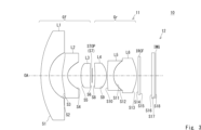
- FIG. 1 is a cross-sectional view showing the configuration of a camera module and an imaging lens system according to Example 1.
- FIG. 3 is a spherical aberration diagram (longitudinal aberration diagram) in the imaging lens system of Example 1.
- FIG. 3 is a field curvature diagram of the imaging lens system of Example 1.
- FIG. 3 is a cross-sectional view showing the configuration of a camera module and an imaging lens system according to Example 2.
- FIG. FIG. 7 is a spherical aberration diagram (longitudinal aberration diagram) in the imaging lens system of Example 2.
- 3 is a field curvature diagram of the imaging lens system of Example 2.
- FIG. 3 is a cross-sectional view showing the configuration of a camera module and an imaging lens system according to Example 3.
- FIG. 7 is a spherical aberration diagram (longitudinal aberration diagram) in the imaging lens system of Example 3.
- FIG. 7 is a curvature of field diagram of the imaging lens system of Example 3.
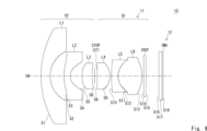
- FIG. 7 is a cross-sectional view showing the configuration of a camera module and an imaging lens system according to Example 4.
- FIG. 7 is a spherical aberration diagram (longitudinal aberration diagram) in the imaging lens system of Example 4.
- FIG. 7 is a field curvature diagram of the imaging lens system of Example 4.
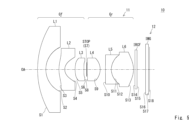
- FIG. 7 is a cross-sectional view showing the configuration of a camera module and an imaging lens system according to Example 5.
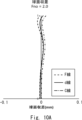
- FIG. 7 is a spherical aberration diagram (longitudinal aberration diagram) in the imaging lens system of Example 5.
- FIG. 7 is a spherical aberration diagram (longitudinal aberration diagram) in the imaging lens system of Example 5.
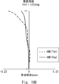
- FIG. 7 is a field curvature diagram of the imaging lens system of Example 5.
- FIG. 7 is a cross-sectional view showing the configuration of a camera module and an imaging lens system according to Example 6.
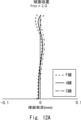
- FIG. 7 is a spherical aberration diagram (longitudinal aberration diagram) in the imaging lens system of Example 6.
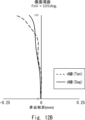
- FIG. 7 is a field curvature diagram of the imaging lens system of Example 6.
- 7 is a cross-sectional view showing the configuration of a camera module and an imaging lens system according to Example 7.
- FIG. FIG. 7 is a spherical aberration diagram (longitudinal aberration diagram) in the imaging lens system of Example 7.
- FIG. 7 is a curvature of field diagram of the imaging lens system of Example 7.
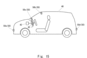
- FIG. 1 is a schematic diagram of a vehicle equipped with an in-vehicle system including a camera module according to an embodiment of the present invention.
- 16 is a block diagram showing the configuration of an imaging device that constitutes the in-vehicle system of FIG. 15.
- FIG. 16 is a schematic diagram of a vehicle equipped with an in-vehicle system including a camera module according to an embodiment of the present invention.
- This embodiment can realize a highly reliable system, especially in a sensing system, and contributes to the development of a resilient infrastructure, and is recognized by the United Nations.
- the Sustainable Development Goals (SDGs) advocated in ⁇ 9. Build the foundations for industry and technological innovation'' include ⁇ 9.1 Economic development with a focus on affordable and fair access for all people.'' The goal is to develop quality, reliable, sustainable and resilient infrastructure, including regional and cross-border infrastructure, to support human well-being.
- the imaging lens system according to Embodiment 1 includes, in order from the object side to the image side, a first lens having a negative power whose object side surface has a convex surface facing the object side, and a first lens having a negative power whose object side surface has a convex surface facing the object side.
- f1/f is -4.0 or less
- the focal length of the first lens is too long relative to the focal length of the entire optical system, in other words, the power of the first lens is too weak.
- the diameter of the first lens cannot be made small. That is, it is not possible to reliably downsize the imaging lens system.
- the value of f1/f is more preferably -3.8 or more, -3.7 or more, still more preferably -3.0 or more.
- the object side surface of the fifth lens has a convex surface facing the object side, it is possible to suppress a decrease in the amount of light condensed at the periphery of the imaging plane (hereinafter referred to as "peripheral light amount"). . Therefore, it is possible to provide a compact imaging lens system.
- the imaging lens system satisfies the following conditional expression (2) when the combined focal length of the first lens and the second lens is defined as f12, and the focal length of the entire optical system is defined as f. -1.2 ⁇ f12/f ⁇ -1.1...(2)
- conditional expression (2) the light rays can be bent gently at the first lens and the second lens, and there is no need to sharply bend the light rays at the first lens. can be suppressed. That is, it is possible to reduce the diameter of the first lens while suppressing the occurrence of aberrations.
- the value of f12/f is -1.2 or less, the combined power of the first lens and the second lens is too weak, and the diameter of the first lens cannot be made sufficiently small.
- the value of f12/f is -1.1 or more, the combined power of the first lens and the second lens is too strong, the aberration generated in the combined lens of the first lens and the second lens becomes too large, and the combined power of the first lens and the second lens becomes too large. It becomes difficult to correct aberrations for the third and subsequent lenses.
- the value of f12/f is more preferably -1.18 or more and -1.12 or less, even more preferably -1.17 or more and -1.13 or less.
- the imaging lens system satisfies the following conditional expression (3) when the focal length of the fifth lens is defined as f5 and the focal length of the entire optical system is defined as f. f5/f ⁇ -2.2...(3)
- conditional expression (3) Aberrations generated in the first lens can be corrected in the fifth lens.
- astigmatism occurs in the first lens because the power of the first lens is strong enough to satisfy the above conditional expression (1).
- the power of the fifth lens is strong enough to satisfy the above conditional expression (3), the astigmatism generated in the first lens can be sufficiently corrected.
- the value of f5/f is -2.2 or more, the power of the fifth lens is too weak, making it difficult to sufficiently correct astigmatism generated in the first lens. More specifically, the value of f5/f is -2.3 or less, -2.4 or less, more preferably -2.5 or less.
- the imaging lens system when the distance on the central optical axis between the object side surface of the first lens and the diaphragm is defined as L1-STOP, and the focal length of the entire optical system is defined as f, the following equation (4) is defined. It is preferable to be satisfied. 4.0 ⁇ (L1-STOP)/f ⁇ 5.5...(4)
- the aperture can be positioned relatively close to the object side, and the entrance pupil can also be positioned relatively close to the object side. be done. Therefore, the diameter of the first lens disposed closest to the object side of the front group can be reduced.
- L1-STOP when the value of L1-STOP is 5.5 or more, the distance between the object side surface of the first lens and the aperture is too long, and it is difficult to form the entrance pupil at a position sufficiently close to the first lens. Therefore, the diameter of the first lens becomes large.
- the value of L1-STOP is -1.1 or more, the distance between the object side of the first lens and the aperture is too short, and the aberrations generated in the front group in front of the aperture become large, and the aberrations in the rear group become large. It becomes impossible to fully compensate for it.
- the value of L1-STOP is more preferably 4.5 or more and 5.0 or less.
- the imaging lens system satisfies the following equation (5) when the effective diameter of the first lens is defined as SD1 and the image height at the maximum angle of view is defined as IH. SD1/IH ⁇ 4.0...(5)
- the diameter of the first lens can be made smaller than the image height at the maximum angle of view.
- the value of SD1/IH is more preferably 3.90 or less.
- the camera module according to Embodiment 2 includes the above-described imaging lens system and an imaging element that is placed at the focal point of the imaging lens system and converts light collected through the imaging lens system into an electrical signal. Thereby, a miniaturized camera module can be provided.
- FIG. 1 is a cross-sectional view showing the configuration of a camera module 10 according to the first embodiment.
- the camera module 10 includes an imaging lens system 11 and an imaging element 12.
- the imaging lens system 11 and the imaging element 12 are housed in a housing (not shown).
- the image sensor 12 is an element that converts received light into an electrical signal, and for example, a CCD image sensor or a CMOS image sensor is used.
- the image sensor 12 is arranged at the imaging position (focal position) of the imaging lens system 11.
- the imaging lens system 11 includes, in order from the object side to the image side, a front group Gf consisting of a first lens L1, a second lens L2, and a third lens L3, an aperture stop (STOP), and a first lens group Gf.
- a rear group Gr includes four lenses L4, a fifth lens L5, and a sixth lens L6.
- the imaging plane of the imaging lens system 11 is indicated by IMG.
- the first lens L1 and the fourth lens L4 are glass lenses.
- the second lens L2, the third lens L3, the fifth lens L5, and the sixth lens L6 are plastic lenses.
- an optical filter infrared cut filter, visible/infrared bandpass filter, etc.
- IRCF infrared cut filter
- the first lens L1 is a glass lens with negative power.
- the object side surface S1 of the first lens L1 has a spherical shape with a convex surface facing the object side.
- the image side surface S2 of the first lens L1 has a spherical shape with a concave surface facing the image side.
- the second lens L2 is a plastic lens with negative power.
- the object side surface S3 of the second lens L2 has an aspherical shape with a convex surface facing the object side.
- the image side surface S4 of the second lens L2 has an aspherical shape with a concave surface facing the image side.
- the third lens L3 is a plastic lens with positive power.
- the object side surface S5 of the third lens L3 has an aspherical shape with a convex surface facing the object side.
- the image side surface S6 of the third lens L3 has an aspherical shape with a concave surface facing the image side.
- Aperture STOP is an aperture that determines the F value (F number, Fno) of the lens system.
- the aperture STOP is arranged between the third lens L3 and the fourth lens L4.
- the fourth lens L4 is a glass lens with positive power.
- the object side surface S8 of the fourth lens L4 has a spherical shape with a convex surface facing the object side.
- the image side surface S9 of the fourth lens L4 has a spherical shape with a convex surface facing the image side.
- the fifth lens L5 is a plastic lens with negative power.
- the object side surface S10 of the fifth lens L5 has an aspherical shape with a convex surface facing the object side.
- the image side surface S11 of the fifth lens L5 has an aspherical shape with a concave surface facing the image side.
- the sixth lens L6 is a plastic lens with positive power.
- the object side surface S12 of the sixth lens L6 has an aspherical shape with a convex surface facing the object side.
- the image side surface S13 of the sixth lens L6 has an aspherical shape with a convex surface facing the image side.
- the fifth lens L5 and the sixth lens L6 constitute a cemented lens. That is, the image side surface S11 of the fifth lens L5 and the object side surface S12 of the sixth lens L6 are in contact with each other.
- An infrared cut filter is a filter for cutting light in the infrared region.
- the infrared cut filter is treated as an integral part of the imaging lens system 11 when designing the imaging lens system 11.
- the infrared cut filter is not an essential component of the imaging lens system 11.
- the infrared cut filter is arranged on the image side of the sixth lens L6.
- a sensor cover glass may be placed between the infrared cut filter and the image sensor 12 in order to prevent dust from adhering to the image sensor 12.
- Table 1 shows lens data for each lens surface in the imaging lens system 11 of Example 1.
- Table 1 presents, as lens data, the radius of curvature (mm) of each surface, the distance between the surfaces at the central optical axis (mm), the refractive index nd for the d-line, and the Abbe number ⁇ d for the d-line.
- surfaces marked with an asterisk (*) indicate that they are aspherical.
- the aspherical shape adopted for the lens surface is 4th, 6th, 8th, 10th, where z is the amount of sag, c is the reciprocal of the radius of curvature, k is the conic coefficient, and r is the height of the ray from the optical axis OA.
- 12th, 14th, and 16th are ⁇ 4 , ⁇ 6 , ⁇ 8 , ⁇ 10 , ⁇ 12 , ⁇ 14 , and ⁇ 16 , respectively, it is expressed by the following equation.
- Table 2 shows aspherical coefficients for defining the aspherical shape of the aspherical lens surface in the imaging lens system 11 of Example 1.
- “-1.05564E-02” means “-1.05564 ⁇ 10 -2 ".
- Numerical expressions are the same for the tables below.
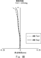
- FIGS. 2A and 2B show a spherical aberration diagram (longitudinal aberration diagram) and a field curvature diagram in the imaging lens system 11 of Example 1.
- the F number is 2.0 and the half angle of view is 105°.
- the horizontal axis indicates the position where the light ray intersects with the optical axis OA, and the vertical axis indicates the height of the light ray passing on the entrance pupil.
- FIG. 2A shows simulation results using the d-line, C-line, and F-line.
- the horizontal axis indicates the distance in the optical axis OA direction
- the vertical axis indicates the image height (field angle).
- Sag indicates the imaging position in the sagittal ray bundle
- Tan indicates the imaging position in the tangential ray bundle.
- FIG. 2B shows simulation results using the d-line.
- FIG. 3 is a sectional view showing the camera module 10 according to the second embodiment.
- the image side surface S6 of the third lens L3 has an aspherical shape with a convex surface facing the image side
- the object side surface S8 of the fourth lens L4 has a concave surface facing the object side.
- the lens configuration is the same as that of Example 1, so a description thereof will be omitted.
- characteristic data of the imaging lens system 11 according to Example 2 will be explained.
- Table 3 shows lens data for each lens surface of the imaging lens system 11 according to Example 2. Since the items shown in Table 3 are the same as those in Table 1, their explanation will be omitted.
- Table 4 shows aspherical coefficients for defining the aspherical shape of the aspherical lens surface in the imaging lens system 11 of Example 2.
- the aspherical shape adopted for the lens surface is expressed by the same formula as in Example 1.
- FIGS. 4A and 4B show a spherical aberration diagram (longitudinal aberration diagram) and a field curvature diagram of the imaging lens system 11 of Example 2. Since the description of each aberration diagram shown in FIGS. 4A and 4B is the same as that of FIGS. 2A and 2B, the description thereof will be omitted.
- FIG. 5 is a sectional view showing the camera module 10 according to the third embodiment.
- the imaging lens system 11 according to the third embodiment has the same lens configuration as the first embodiment, except that the image side surface S6 of the third lens L3 has an aspherical shape with a convex surface facing the image side. omitted.
- characteristic data of the imaging lens system 11 according to Example 3 will be explained.
- Table 5 shows lens data for each lens surface of the imaging lens system 11 according to Example 3. Since the items shown in Table 5 are the same as those in Table 1, their explanation will be omitted.
- Table 6 shows aspherical coefficients for defining the aspherical shape of the aspherical lens surface in the imaging lens system 11 of Example 3.
- the aspherical shape adopted for the lens surface is expressed by the same formula as in Example 1.
- FIGS. 6A and 6B show a spherical aberration diagram (longitudinal aberration diagram) and a field curvature diagram of the imaging lens system 11 of Example 3. Since the description of each aberration diagram shown in FIGS. 6A and 6B is the same as that of FIGS. 2A and 2B, the description thereof will be omitted.
- FIG. 7 is a sectional view showing the camera module 10 according to the fourth embodiment.
- the imaging lens system 11 according to the fourth embodiment has the same lens configuration as the first embodiment, except that the image side surface S6 of the third lens L3 has an aspherical shape with a convex surface facing the image side. omitted.
- characteristic data of the imaging lens system 11 according to Example 4 will be explained.
- Table 7 shows lens data for each lens surface of the imaging lens system 11 according to Example 4.
- the items shown in Table 7 are the same as those in Table 1, so their explanation will be omitted.
- Table 8 shows aspherical coefficients for defining the aspherical shape of the aspherical lens surface in the imaging lens system 11 of Example 4.
- the aspherical shape adopted for the lens surface is expressed by the same formula as in Example 1.
- FIGS. 8A and 8B show a spherical aberration diagram (longitudinal aberration diagram) and a field curvature diagram of the imaging lens system 11 of Example 4. Since the description of each aberration diagram shown in FIGS. 8A and 8B is the same as that of FIGS. 2A and 2B, the description thereof will be omitted.
- FIG. 9 is a sectional view showing the camera module 10 according to the fifth embodiment.
- the image side surface S6 of the third lens L3 has an aspherical shape with a convex surface facing the image side
- the object side surface S8 of the fourth lens L4 has a concave surface facing the object side.
- the lens configuration is the same as that of Example 1, so the explanation thereof will be omitted.
- characteristic data of the imaging lens system 11 according to Example 5 will be explained.
- Table 9 shows lens data for each lens surface of the imaging lens system 11 according to Example 5.
- the items shown in Table 9 are the same as those in Table 1, so the description thereof will be omitted.
- Table 10 shows aspherical coefficients for defining the aspherical shape of the aspherical lens surface in the imaging lens system 11 of Example 5.
- the aspherical shape adopted for the lens surface is expressed by the same formula as in Example 1.
- FIGS. 10A and 10B show a spherical aberration diagram (longitudinal aberration diagram) and a field curvature diagram of the imaging lens system 11 of Example 5. Since the description of each aberration diagram shown in FIGS. 10A and 10B is the same as that of FIGS. 2A and 2B, the description thereof will be omitted.
- FIG. 11 is a sectional view showing the camera module 10 according to the sixth embodiment.
- the image side surface S6 of the third lens L3 has an aspherical shape with a convex surface facing the image side
- the object side surface S8 of the fourth lens L4 has a concave surface facing the object side.
- the lens configuration is the same as that of Example 1, so a description thereof will be omitted.
- characteristic data of the imaging lens system 11 according to Example 6 will be explained.
- Table 11 shows lens data for each lens surface of the imaging lens system 11 according to Example 6.
- the items shown in Table 11 are the same as those in Table 1, so their explanation will be omitted.
- Table 12 shows aspherical coefficients for defining the aspherical shape of the aspherical lens surface in the imaging lens system 11 of Example 6.
- the aspherical shape adopted for the lens surface is expressed by the same formula as in Example 1.
- FIGS. 12A and 12B show a spherical aberration diagram (longitudinal aberration diagram) and a field curvature diagram of the imaging lens system 11 of Example 6. Since the description of each aberration diagram shown in FIGS. 12A and 12B is the same as that of FIGS. 2A and 2B, the description thereof will be omitted.
- FIG. 13 is a sectional view showing the camera module 10 according to the seventh embodiment.
- the imaging lens system 11 according to the seventh embodiment has a lens configuration similar to that of the first embodiment, so the description thereof will be omitted.
- characteristic data of the imaging lens system 11 according to Example 7 will be explained.
- Table 13 shows lens data for each lens surface of the imaging lens system 11 according to Example 7. Since the items shown in Table 13 are the same as those in Table 1, their explanation will be omitted.
- Table 14 shows aspherical coefficients for defining the aspherical shape of the aspherical lens surface in the imaging lens system 11 of Example 7.
- the aspherical shape adopted for the lens surface is expressed by the same formula as in Example 1.
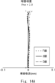
- FIGS. 14A and 14B show a spherical aberration diagram (longitudinal aberration diagram) and a field curvature diagram of the imaging lens system 11 of Example 7. Since the description of each aberration diagram shown in FIGS. 14A and 14B is the same as that of FIGS. 2A and 2B, the description thereof will be omitted.
- Table 15 shows the total optical length TTL of the imaging lens system 11, the focal length f1 of the first lens L1, the focal length f2 of the second lens L2, the focal length f3 of the third lens L3, the focal length f4 of the fourth lens L4, and the focal length f4 of the fourth lens L4.
- the diameter of the first lens L1 can be reduced by making the value of f1/f satisfy conditional expression (2).
- the value of SD1/IH is 3.887 to 3.909, and the diameter of the first lens L1 is sufficiently small with respect to the image height of the maximum angle of view. I am able to do that.
- the object side surface of the fifth lens L5 has a convex surface facing the object side, it is possible to suppress a decrease in the amount of peripheral light.
- Examples 1 to 7 by making the value of f12/f satisfy the above conditional expression (2), it is possible to reduce the diameter of the first lens L1 and suppress aberrations occurring in the first lens L1. be able to.
- the camera module 10 includes the imaging lens system 11, and the imaging lens system 11 is miniaturized and has sufficient resolution necessary for image recognition in automatic driving, so that the camera module 10 can be miniaturized and high-precision sensing can be performed. can be achieved.
- FIG. 15 shows an on-vehicle system equipped with an imaging device 50 including an imaging lens system 11 according to Embodiment 1 or Embodiment 2 and an imaging device 12 that converts light collected through the imaging lens system into an electrical signal.
- FIG. 4 is a schematic diagram of a vehicle 40.
- the imaging device 50 can be mounted on the vehicle 40
- FIG. 15 is an arrangement example illustrating the mounting position of the imaging device 50 in the vehicle 40.
- the imaging device 50 mounted on the vehicle 40 can also be called an on-vehicle camera, and can be installed at various locations on the vehicle 40.
- the first imaging device 50a may be disposed at or near the front bumper as a camera that monitors the front when the vehicle 40 is traveling.
- the second imaging device 50b that monitors the front may be placed near an interior rearview mirror of the vehicle 40.
- the third imaging device 50c may be placed on the dashboard or inside the instrument panel as a camera that monitors the driving situation of the driver.
- the fourth imaging device 50d may be installed at the rear of the vehicle 40 for monitoring the rear of the vehicle 40.
- the imaging devices 50a, 50b can be called front cameras.
- the third imaging device 50c can be called an in-camera.
- the fourth imaging device 50d can be called a rear camera.
- the imaging device 50 is not limited to these, and includes imaging devices installed at various positions, such as a left side camera that images the left rear side and a right side camera that images the right rear side.
- the image signal of the image captured by the imaging device 50 may be output to the information processing device 42 and/or the display device 43 in the vehicle 40.
- These information processing device 42 and display device 43 together with the imaging device 50 constitute an in-vehicle system.
- the information processing device 42 in the vehicle 40 includes a device that processes image signals acquired by the imaging device 50, recognizes various objects in the captured image, and assists the driver in driving. Further, the information processing device 42 includes, for example, a navigation device, a collision damage mitigation braking device, an inter-vehicle distance control device, a lane departure warning device, etc., but is not limited thereto.
- the display device 43 displays images processed and output by the information processing device 42, but can also directly receive image signals from the imaging device 50.
- the display device 43 may employ a liquid crystal display (LCD), an organic EL (electro-luminescence) display, or an inorganic EL display, but is not limited to these.
- the display device 43 can display an image signal output from an imaging device 50 such as a rear camera that captures an image at a position that is difficult for the driver to see, to a passenger such as the driver.
- an imaging device 50 such as a rear camera that captures an image at a position that is difficult for the driver to see, to a passenger such as the driver.
- FIG. 16 shows the configuration of an imaging device 50 that constitutes the in-vehicle system of FIG. 15.
- an imaging device 50 according to one embodiment includes a control section 52, a storage section 54, and a camera module 10.
- the control unit 52 controls the camera module 10 and processes electrical signals output from the image sensor 12 of the camera module 10.
- This control unit 52 may be configured as a processor, for example. Further, the control unit 52 may include one or more processors.
- the processor may include a general-purpose processor that loads a specific program to execute a specific function, and a dedicated processor specialized for specific processing.
- the dedicated processor may include an application-specific integrated circuit (IC).
- An IC for a specific application is also called an ASIC (Application Specific Integrated Circuit).
- the processor may include a programmable logic device.
- a programmable logic device is also called a PLD (Programmable Logic Device).
- the PLD may include an FPGA (Field-Programmable Gate Array).
- the control unit 52 may be either an SoC (System-on-a-Chip) or an SiP (System In a Package) in which one or more processors cooperate.
- the storage unit 54 stores various information or parameters related to the operation of the imaging device 50.
- the storage unit 54 may be composed of, for example, a semiconductor memory.
- the storage unit 54 may function as a work memory for the control unit 52.
- the storage unit 54 may store captured images.
- the storage unit 54 may store various parameters and the like for the control unit 52 to perform detection processing based on the captured image.
- the storage unit 54 may be included in the control unit 52.
- the camera module 10 captures a subject image formed through the imaging lens system 11 with the imaging element 12, and outputs the captured image.
- the image captured by the camera module 10 is also referred to as a captured image.
- the image sensor 12 may be configured with, for example, a CMOS (Complementary Metal Oxide Semiconductor) image sensor or a CCD (Charge Coupled Device).
- the image sensor 12 has an imaging surface on which a plurality of pixels are lined up. Each pixel outputs a signal specified by current or voltage depending on the amount of incident light. The signal output by each pixel is also referred to as imaging data.
- Imaging data may be read out by the camera module 10 for all pixels and taken into the control unit 52 as a captured image.
- the captured image read out for all pixels is also referred to as the maximum captured image.
- the image data may be read out by the camera module 10 for some pixels and captured as a captured image. In other words, the imaging data may be read from pixels within a predetermined capture range. Image data read from pixels in a predetermined capture range may be captured as a captured image.
- the predetermined capture range may be set by the control unit 52.
- the camera module 10 may acquire a predetermined capture range from the control unit 52.
- the image sensor 12 may capture an image within a predetermined capture range of the subject image formed through the image pickup lens system 11 .
- the present invention is not limited to the above embodiments, and can be modified as appropriate without departing from the spirit.
- the application of the imaging lens system of the present invention is not limited to in-vehicle cameras and surveillance cameras, but can also be used for other applications such as being installed in small electronic devices such as mobile phones.
- Imaging module 11 Imaging lens system 12 Imaging element 40 Vehicle (mobile object) 42 Information processing device (processing device) 43 Display device (output device) 50 Imaging device 52 Control unit L1 First lens L2 Second lens L3 Third lens L4 Fourth lens L5 Fifth lens L6 Sixth lens STOP Aperture Gf Front group Gr Rear group IRCF Infrared cut filter IMG Image plane OA Optical axis
Landscapes
- Physics & Mathematics (AREA)
- General Physics & Mathematics (AREA)
- Optics & Photonics (AREA)
- Lenses (AREA)
Abstract
小型化された撮像レンズ系、カメラモジュール、車載システム、移動体を提供する。撮像レンズ系(11)は、物体側から像側に向かって順に、物体側面が物体側に凸面を向けた負のパワーを有する第1レンズ(L1)、物体側面が物体側に凸面を向けた負のパワーを有する第2レンズ(L2)、物体側面が物体側に凸面を向けた正のパワーを有する第3レンズ(L3)、絞りSTOP、像側面が像側に凸面を向けた正のパワーを有する第4レンズ(L4)、物体側面が物体側に凸面を向けた負のパワーを有する第5レンズ(L5)、正のパワーを有する第6レンズ(L6)、からなり、第5レンズ(L5)と第6レンズ(L6)とは接合レンズを構成し、第1レンズ(L1)の焦点距離をf1、光学系全体の焦点距離をfと定義したときに、条件式(1)を満足する。
Description
本発明は、撮像レンズ系、カメラモジュール、車載システム、移動体に関する。
近年、車載カメラにはセンシング機能が求められるようになってきており、撮像素子の解像度が高くなり、大型化しつつある。これに伴い、車載カメラ等に搭載される撮像レンズ系も大きくなる傾向にある。一方、車両の周囲の全方位センシングの要求により、車載カメラがサイドミラー等の空間的に制限のある位置に取り付けられるようになりつつある。そのため、車載カメラの小型化が求められつつある。また、石や砂利等の衝突の可能性を下げるため、第1レンズの小径化も求められている。
特許文献1には、車載カメラ等に搭載される、6枚のレンズからなる魚眼レンズのレンズ系が記載されている。
特許文献1には、車載カメラ等に搭載される、6枚のレンズからなる魚眼レンズのレンズ系が記載されている。
しかしながら、特許文献1に記載の撮像レンズ系は、光学全長TTLと光学系全体の焦点距離fとの比TTL/fが13.560~13.669であり、比較的大きい光学系となっている。
本発明は、このような問題点に鑑みてなされたものであり、小型化された撮像レンズ系、カメラモジュール、車載システム、移動体を提供することを目的とする。
一実施形態の撮像レンズ系は、物体側から像側に向かって順に、物体側面が物体側に凸面を向けた負のパワーを有する第1レンズ、物体側面が物体側に凸面を向けた負のパワーを有する第2レンズ、物体側面が物体側に凸面を向けた正のパワーを有する第3レンズ、絞り、像側面が像側に凸面を向けた正のパワーを有する第4レンズ、物体側面が物体側に凸面を向けた負のパワーを有する第5レンズ、正のパワーを有する第6レンズ、からなり、
前記第5レンズと前記第6レンズとは接合レンズを構成し、
前記第1レンズの焦点距離をf1、光学系全体の焦点距離をfと定義したときに、以下の条件式(1)を満足することを特徴とする、
撮像レンズ系。
-4.0<f1/f・・・(1)
前記第5レンズと前記第6レンズとは接合レンズを構成し、
前記第1レンズの焦点距離をf1、光学系全体の焦点距離をfと定義したときに、以下の条件式(1)を満足することを特徴とする、
撮像レンズ系。
-4.0<f1/f・・・(1)
本発明によれば、小型化された撮像レンズ系、カメラモジュール、車載システム、移動体を提供することができる。
以下、図面を参照しながら本発明の実施の形態について説明するが、本実施形態は、特にセンシングシステムにおいて信頼性の高いシステムを実現でき、強靭なインフラの開発に貢献するものであり、国連の提唱する持続可能な開発目標(SDGs:Sustainable Development Goals)の「9.産業と技術革新の基盤をつくろう」の、「9.1 すべての人々に安価で公平なアクセスに重点を置いた経済発展と人間の福祉を支援するために、地域・越境インフラを含む質の高い、信頼でき、持続可能かつ強靱(レジリエント)なインフラを開発する。」をターゲットとするものである。
(実施の形態1:撮像レンズ系)
実施の形態1に係る撮像レンズ系は、物体側から像側に向かって順に、物体側面が物体側に凸面を向けた負のパワーを有する第1レンズ、物体側面が物体側に凸面を向けた負のパワーを有する第2レンズ、物体側面が物体側に凸面を向けた正のパワーを有する第3レンズ、絞り、像側面が像側に凸面を向けた正のパワーを有する第4レンズ、物体側面が物体側に凸面を向けた負のパワーを有する第5レンズ、正のパワーを有する第6レンズ、からなり、
第5レンズと第6レンズとは接合レンズを構成し、
第1レンズの焦点距離をf1、光学系全体の焦点距離をfと定義したときに、以下の条件式(1)を満足する。
-4.0<f1/f・・・(1)
(実施の形態1:撮像レンズ系)
実施の形態1に係る撮像レンズ系は、物体側から像側に向かって順に、物体側面が物体側に凸面を向けた負のパワーを有する第1レンズ、物体側面が物体側に凸面を向けた負のパワーを有する第2レンズ、物体側面が物体側に凸面を向けた正のパワーを有する第3レンズ、絞り、像側面が像側に凸面を向けた正のパワーを有する第4レンズ、物体側面が物体側に凸面を向けた負のパワーを有する第5レンズ、正のパワーを有する第6レンズ、からなり、
第5レンズと第6レンズとは接合レンズを構成し、
第1レンズの焦点距離をf1、光学系全体の焦点距離をfと定義したときに、以下の条件式(1)を満足する。
-4.0<f1/f・・・(1)
これにより、小型化された撮像レンズ系を提供することができる。
具体的には、f1/fの値が-4.0以下の場合、光学系全体の焦点距離に対して第1レンズの焦点距離が長すぎ、換言すれば、第1レンズのパワーが弱すぎ、第1レンズにおいて光線を十分に曲げることができないため第1レンズの径を小さくすることができない。すなわち、撮像レンズ系を確実に小型化することができない。f1/fの値は、より好ましくは-3.8以上、-3.7以上、さらに好ましくは-3.0以上である。
また、第5レンズの物体側面が物体側に凸面を向けていることにより、結像面の周辺部に集光する光量(以下、「周辺光量」と称する。)の低下を抑制することができる。
よって、小型化された撮像レンズ系を提供することができる。
具体的には、f1/fの値が-4.0以下の場合、光学系全体の焦点距離に対して第1レンズの焦点距離が長すぎ、換言すれば、第1レンズのパワーが弱すぎ、第1レンズにおいて光線を十分に曲げることができないため第1レンズの径を小さくすることができない。すなわち、撮像レンズ系を確実に小型化することができない。f1/fの値は、より好ましくは-3.8以上、-3.7以上、さらに好ましくは-3.0以上である。
また、第5レンズの物体側面が物体側に凸面を向けていることにより、結像面の周辺部に集光する光量(以下、「周辺光量」と称する。)の低下を抑制することができる。
よって、小型化された撮像レンズ系を提供することができる。
また、撮像レンズ系は、第1レンズと第2レンズの合成焦点距離をf12、光学系全体の焦点距離をfと定義したときに、以下の条件式(2)を満足することが好ましい。
-1.2<f12/f<-1.1・・・(2)
上記の条件式(2)を満足することにより、第1レンズ及び第2レンズにおいて光線を緩やかに曲げることができ、第1レンズにおいて光線を急激に曲げる必要がなくなり、第1レンズで発生する収差を抑制することができる。すなわち、収差の発生を抑制しながら第1レンズの小径化を図ることができる。具体的には、f12/fの値が-1.2以下の場合、第1レンズと第2レンズの合成パワーが弱すぎ、第1レンズの径を十分に小さくすることができない。一方、f12/fの値が-1.1以上の場合、第1レンズと第2レンズの合成パワーが強すぎ、第1レンズと第2レンズの合成レンズで発生する収差が大きくなりすぎ、第3レンズ以降のレンズにおいて収差補正を行うことが難しくなる。f12/fの値は、より好ましくは-1.18以上、-1.12以下、さらに好ましくは-1.17以上、-1.13以下である。
-1.2<f12/f<-1.1・・・(2)
上記の条件式(2)を満足することにより、第1レンズ及び第2レンズにおいて光線を緩やかに曲げることができ、第1レンズにおいて光線を急激に曲げる必要がなくなり、第1レンズで発生する収差を抑制することができる。すなわち、収差の発生を抑制しながら第1レンズの小径化を図ることができる。具体的には、f12/fの値が-1.2以下の場合、第1レンズと第2レンズの合成パワーが弱すぎ、第1レンズの径を十分に小さくすることができない。一方、f12/fの値が-1.1以上の場合、第1レンズと第2レンズの合成パワーが強すぎ、第1レンズと第2レンズの合成レンズで発生する収差が大きくなりすぎ、第3レンズ以降のレンズにおいて収差補正を行うことが難しくなる。f12/fの値は、より好ましくは-1.18以上、-1.12以下、さらに好ましくは-1.17以上、-1.13以下である。
また、撮像レンズ系は、第5レンズの焦点距離をf5、光学系全体の焦点距離をfと定義したときに、以下の条件式(3)を満足することが好ましい。
f5/f<-2.2・・・(3)
上記の条件式(3)を満足することにより、第1レンズにおいて発生した収差を第5レンズにおいて補正することができる。具体的には、第1レンズのパワーが上記の条件式(1)を満たす程度に強いことにより、第1レンズにおいて非点収差が発生する。しかし、第5レンズのパワーが上記の条件式(3)を満たす程度に強いことにより、第1レンズにおいて発生した非点収差を十分に補正することができる。換言すれば、f5/fの値が-2.2以上の場合、第5レンズのパワーが弱すぎ、第1レンズにおいて発生した非点収差を十分に補正することが難しくなる。より具体的には、f5/fの値は、-2.3以下、-2.4以下、さらに好ましくは、-2.5以下である。
f5/f<-2.2・・・(3)
上記の条件式(3)を満足することにより、第1レンズにおいて発生した収差を第5レンズにおいて補正することができる。具体的には、第1レンズのパワーが上記の条件式(1)を満たす程度に強いことにより、第1レンズにおいて非点収差が発生する。しかし、第5レンズのパワーが上記の条件式(3)を満たす程度に強いことにより、第1レンズにおいて発生した非点収差を十分に補正することができる。換言すれば、f5/fの値が-2.2以上の場合、第5レンズのパワーが弱すぎ、第1レンズにおいて発生した非点収差を十分に補正することが難しくなる。より具体的には、f5/fの値は、-2.3以下、-2.4以下、さらに好ましくは、-2.5以下である。
また、撮像レンズ系は、第1レンズの物体側面と絞りとの間の中心光軸における距離をL1-STOP、光学系全体の焦点距離をfと定義したときに、以下の式(4)を満足することが好ましい。
4.0<(L1-STOP)/f<5.5・・・(4)
撮像レンズ系が上記の条件式(4)を満足することにより、絞りの位置を物体側に比較的近い位置に配置することができるため、入射瞳の位置も物体側に比較的近い位置に形成される。そのため、前群の最も物体側に配置される第1レンズの小径化を図ることができる。具体的には、L1-STOPの値が5.5以上の場合、第1レンズの物体側面と絞りとの距離が長すぎ、第1レンズから十分に近い位置に入射瞳を形成することが難しくなり、第1レンズの径が大きくなってしまう。一方、L1-STOPの値が-1.1以上の場合、第1レンズの物体側面と絞りとの距離が短すぎ、絞りより前の前群で発生する収差が大きくなり、後群においてその収差を補正しきれなくなってしまう。L1-STOPの値は、より好ましくは4.5以上、5.0以下である。
4.0<(L1-STOP)/f<5.5・・・(4)
撮像レンズ系が上記の条件式(4)を満足することにより、絞りの位置を物体側に比較的近い位置に配置することができるため、入射瞳の位置も物体側に比較的近い位置に形成される。そのため、前群の最も物体側に配置される第1レンズの小径化を図ることができる。具体的には、L1-STOPの値が5.5以上の場合、第1レンズの物体側面と絞りとの距離が長すぎ、第1レンズから十分に近い位置に入射瞳を形成することが難しくなり、第1レンズの径が大きくなってしまう。一方、L1-STOPの値が-1.1以上の場合、第1レンズの物体側面と絞りとの距離が短すぎ、絞りより前の前群で発生する収差が大きくなり、後群においてその収差を補正しきれなくなってしまう。L1-STOPの値は、より好ましくは4.5以上、5.0以下である。
また、撮像レンズ系は、第1レンズの有効径をSD1、最大画角の像高をIHと定義したときに、以下の式(5)を満足することが好ましい。
SD1/IH<4.0・・・(5)
撮像レンズ系が上記の条件式(5)を満足することにより、第1レンズの径を最大画角の像高に対して、小さくすることができる。SD1/IHの値は、より好ましくは、3.90以下である。
SD1/IH<4.0・・・(5)
撮像レンズ系が上記の条件式(5)を満足することにより、第1レンズの径を最大画角の像高に対して、小さくすることができる。SD1/IHの値は、より好ましくは、3.90以下である。
(実施の形態2:カメラモジュール)
実施の形態2に係るカメラモジュールは、上述の撮像レンズ系と、当該撮像レンズ系の焦点位置に配置され、撮像レンズ系を通じて集光される光を電気信号に変換する撮像素子と、を備える。これにより、小型化されたカメラモジュールを提供することができる。
実施の形態2に係るカメラモジュールは、上述の撮像レンズ系と、当該撮像レンズ系の焦点位置に配置され、撮像レンズ系を通じて集光される光を電気信号に変換する撮像素子と、を備える。これにより、小型化されたカメラモジュールを提供することができる。
次に、実施の形態1に係る撮像レンズ系及び実施の形態2に係るカメラモジュールに対応する実施例について、図面を参照して説明する。
(実施例1)
図1は、実施例1のカメラモジュール10の構成を示す断面図である。具体的には、カメラモジュール10は、撮像レンズ系11と、撮像素子12と、を備える。撮像レンズ系11と撮像素子12とは筐体(不図示)に収容されている。
(実施例1)
図1は、実施例1のカメラモジュール10の構成を示す断面図である。具体的には、カメラモジュール10は、撮像レンズ系11と、撮像素子12と、を備える。撮像レンズ系11と撮像素子12とは筐体(不図示)に収容されている。
撮像素子12は、受光した光を電気信号に変換する素子であり、例えば、CCDイメージセンサやCMOSイメージセンサが用いられる。撮像素子12は、撮像レンズ系11の結像位置(焦点位置)に配置されている。
実施例1に係る撮像レンズ系11は、物体側から像側に向かって順に、第1レンズL1、第2レンズL2、第3レンズL3からなる前群Gfと、開口絞り(STOP)と、第4レンズL4、第5レンズL5、第6レンズL6からなる後群Grと、からなる。撮像レンズ系11の結像面はIMGで示されている。第1レンズL1、第4レンズL4は、ガラスレンズである。第2レンズL2、第3レンズL3、第5レンズL5、第6レンズL6はプラスチックレンズである。
なお、撮像レンズ系11と撮像素子12との間には、必要に応じて、光学フィルタ(赤外線カットフィルタ、可視・赤外光バンドパスフィルタ等)が配置される。本明細書では、撮像レンズ系11と撮像素子12との間に、赤外線カットフィルタ(IRCF)が配置された例を挙げて説明する。
なお、撮像レンズ系11と撮像素子12との間には、必要に応じて、光学フィルタ(赤外線カットフィルタ、可視・赤外光バンドパスフィルタ等)が配置される。本明細書では、撮像レンズ系11と撮像素子12との間に、赤外線カットフィルタ(IRCF)が配置された例を挙げて説明する。
第1レンズL1は、負のパワーを有するガラスレンズである。第1レンズL1の物体側面S1は、物体側に凸面を向けた球面形状を有する。第1レンズL1の像側面S2は、像側に凹面を向けた球面形状を有する。
第2レンズL2は、負のパワーを有するプラスチックレンズである。第2レンズL2の物体側面S3は、物体側に凸面を向けた非球面形状を有する。第2レンズL2の像側面S4は、像側に凹面を向けた非球面形状を有する。
第3レンズL3は、正のパワーを有するプラスチックレンズである。第3レンズL3の物体側面S5は、物体側に凸面を向けた非球面形状を有する。また、第3レンズL3の像側面S6は、像側に凹面を向けた非球面形状を有する。
絞りSTOPは、レンズ系のF値(Fナンバ、Fno)を決める絞りである。絞りSTOPは、第3レンズL3と第4レンズL4との間に配置される。
第4レンズL4は、正のパワーを有するガラスレンズである。第4レンズL4の物体側面S8は、物体側に凸面を向けた球面形状を有する。また、第4レンズL4の像側面S9は、像側に凸面を向けた球面形状を有する。
第5レンズL5は、負のパワーを有するプラスチックレンズである。第5レンズL5の物体側面S10は、物体側に凸面を向けた非球面形状を有する。また、第5レンズL5の像側面S11は、像側に凹面を向けた非球面形状を有する。
第6レンズL6は、正のパワーを有するプラスチックレンズである。第6レンズL6の物体側面S12は、物体側に凸面を向けた非球面形状を有する。また、第6レンズL6の像側面S13は、像側に凸面を向けた非球面形状を有する。
第5レンズL5と第6レンズL6は、接合レンズを構成している。すなわち、第5レンズL5の像側面S11と第6レンズL6の物体側面S12とが接している。
赤外線カットフィルタ(IRCF)は、赤外領域の光をカットするためのフィルタである。赤外線カットフィルタは、撮像レンズ系11の設計時には、撮像レンズ系11と一体として扱われる。しかし、赤外線カットフィルタは、撮像レンズ系11の必須の構成要素ではない。赤外線カットフィルタは、第6レンズL6の像側に配置されている。
また、赤外線カットフィルタと撮像素子12との間に、撮像素子12へのごみ付着防止のため、センサーカバーガラスが配置されてもよい。
また、赤外線カットフィルタと撮像素子12との間に、撮像素子12へのごみ付着防止のため、センサーカバーガラスが配置されてもよい。
表1に、実施例1の撮像レンズ系11における、各レンズ面のレンズデータを示す。表1では、レンズデータとして、各面の曲率半径(mm)、中心光軸における面間隔(mm)、d線に対する屈折率nd、d線に対するアッベ数νdを提示している。また、表1において、「*印」がついた面は、非球面であることを示している。

レンズ面に採用される非球面形状は、zをサグ量、cを曲率半径の逆数、kを円錐係数、rを光軸OAからの光線高さとして、4次、6次、8次、10次、12次、14次、16次の非球面係数をそれぞれα4、α6、α8、α10、α12、α14、α16としたときに、次式により表わされる。

表2に、実施例1の撮像レンズ系11において、非球面とされたレンズ面の非球面形状を規定するための非球面係数を示す。なお、表2において、例えば「-1.05564E-02」は、「-1.05564×10⁻²」を意味する。以下の表についても数値の表現は同様である。

次に、収差について図面を用いて説明する。図2A及び図2Bは、実施例1の撮像レンズ系11における球面収差図(縦収差図)、像面湾曲図を示す。図2A及び図2Bに示すように、実施例1の撮像レンズ系11では、Fナンバが2.0であり、半画角が105°である。
また、図2Aの縦収差図において、横軸は光線が光軸OAと交わる位置を示し、縦軸は入射瞳上における光線の通過高さを示す。また、図2Aは、d線、C線、F線によるシミュレーション結果を示している。
また、図2Bの像面湾曲図において、横軸は光軸OA方向の距離を示し、縦軸は像高(画角)を示す。また、図2Bの像面湾曲図において、Sagはサジタル光線束における結像位置を示し、Tanはタンジェンシャル光線束における結像位置を示す。また、図2Bは、d線によるシミュレーション結果を示している。
また、図2Aの縦収差図において、横軸は光線が光軸OAと交わる位置を示し、縦軸は入射瞳上における光線の通過高さを示す。また、図2Aは、d線、C線、F線によるシミュレーション結果を示している。
また、図2Bの像面湾曲図において、横軸は光軸OA方向の距離を示し、縦軸は像高(画角)を示す。また、図2Bの像面湾曲図において、Sagはサジタル光線束における結像位置を示し、Tanはタンジェンシャル光線束における結像位置を示す。また、図2Bは、d線によるシミュレーション結果を示している。
(実施例2)
図3は、実施例2に係るカメラモジュール10を示す断面図である。実施例2に係る撮像レンズ系11は、第3レンズL3の像側面S6が像側に凸面を向けた非球面形状を有し、第4レンズL4の物体側面S8が物体側に凹面を向けた球面形状を有すること以外は、実施例1と同様のレンズ構成を有するため、その説明を省略する。以下、実施例2に係る撮像レンズ系11の特性データについて説明する。
図3は、実施例2に係るカメラモジュール10を示す断面図である。実施例2に係る撮像レンズ系11は、第3レンズL3の像側面S6が像側に凸面を向けた非球面形状を有し、第4レンズL4の物体側面S8が物体側に凹面を向けた球面形状を有すること以外は、実施例1と同様のレンズ構成を有するため、その説明を省略する。以下、実施例2に係る撮像レンズ系11の特性データについて説明する。
表3に、実施例2に係る撮像レンズ系11の各レンズ面のレンズデータを示す。表3に示す項目は、表1と同様であるため、その説明を省略する。
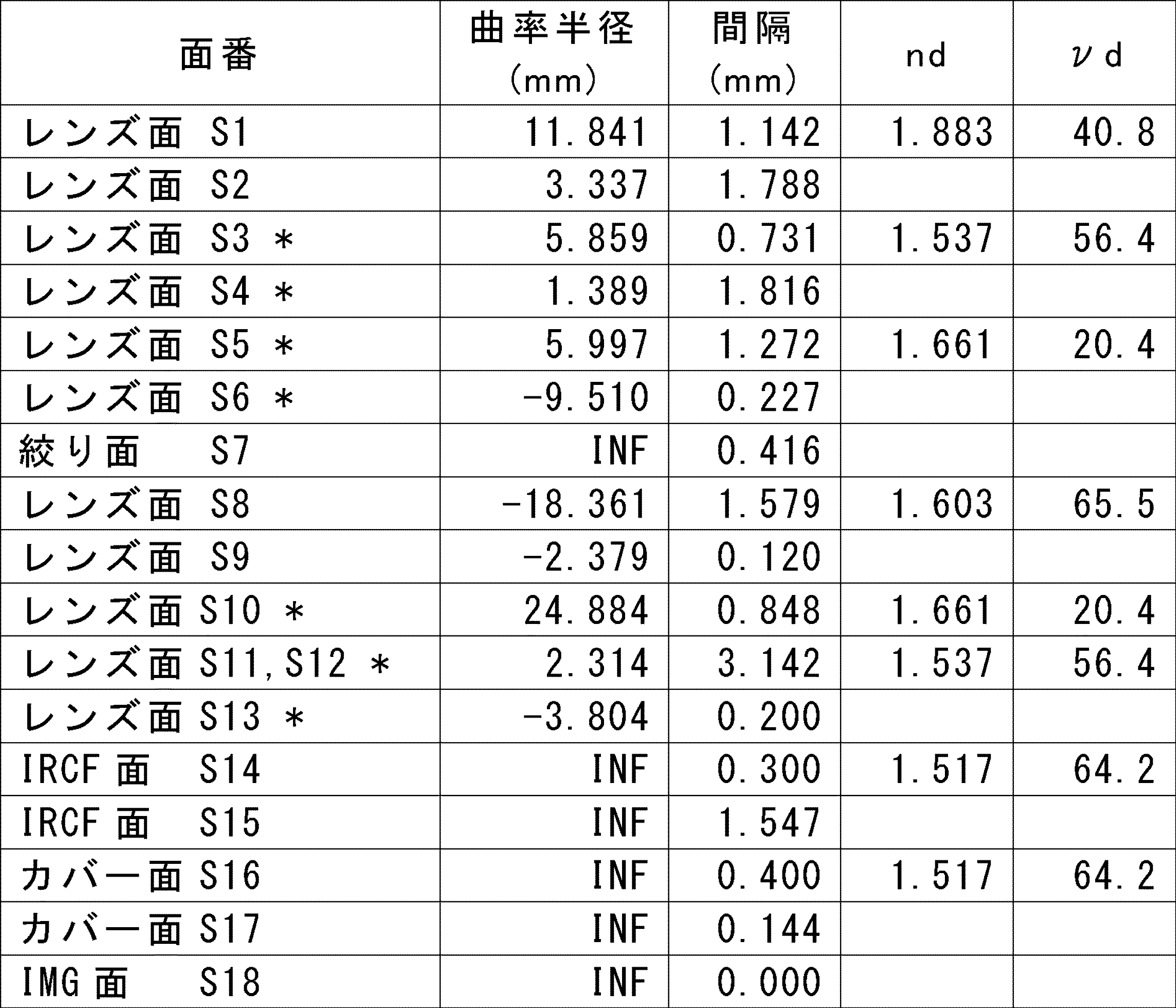
表4に、実施例2の撮像レンズ系11において、非球面とされたレンズ面の非球面形状を規定するための非球面係数を示す。表4において、レンズ面に採用される非球面形状は、実施例1と同様の式にて表される。

図4A及び図4Bに、実施例2の撮像レンズ系11における球面収差図(縦収差図)、像面湾曲図を示す。図4A及び図4Bに示す各収差図についての説明は図2A及び図2Bと同様であるため、その説明を省略する。
(実施例3)
図5は、実施例3に係るカメラモジュール10を示す断面図である。実施例3に係る撮像レンズ系11は、第3レンズL3の像側面S6が像側に凸面を向けた非球面形状を有すること以外は、実施例1と同様のレンズ構成を有するため、その説明を省略する。以下、実施例3に係る撮像レンズ系11の特性データについて説明する。
図5は、実施例3に係るカメラモジュール10を示す断面図である。実施例3に係る撮像レンズ系11は、第3レンズL3の像側面S6が像側に凸面を向けた非球面形状を有すること以外は、実施例1と同様のレンズ構成を有するため、その説明を省略する。以下、実施例3に係る撮像レンズ系11の特性データについて説明する。
表5に、実施例3に係る撮像レンズ系11の各レンズ面のレンズデータを示す。表5に示す項目は、表1と同様であるため、その説明を省略する。

表6に、実施例3の撮像レンズ系11において、非球面とされたレンズ面の非球面形状を規定するための非球面係数を示す。表6において、レンズ面に採用される非球面形状は、実施例1と同様の式にて表される。
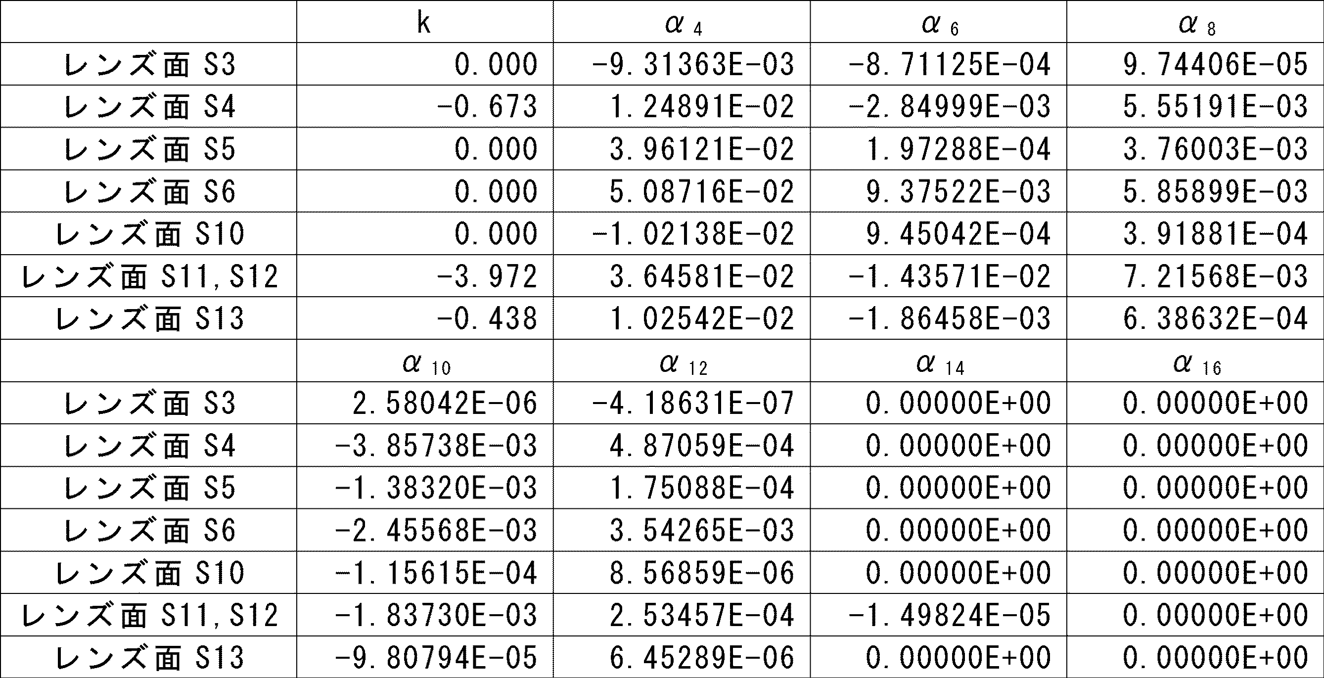
図6A及び図6Bに、実施例3の撮像レンズ系11における球面収差図(縦収差図)、像面湾曲図を示す。図6A及び図6Bに示す各収差図についての説明は図2A及び図2Bと同様であるため、その説明を省略する。
(実施例4)
図7は、実施例4に係るカメラモジュール10を示す断面図である。実施例4に係る撮像レンズ系11は、第3レンズL3の像側面S6が像側に凸面を向けた非球面形状を有すること以外は、実施例1と同様のレンズ構成を有するため、その説明を省略する。以下、実施例4に係る撮像レンズ系11の特性データについて説明する。
図7は、実施例4に係るカメラモジュール10を示す断面図である。実施例4に係る撮像レンズ系11は、第3レンズL3の像側面S6が像側に凸面を向けた非球面形状を有すること以外は、実施例1と同様のレンズ構成を有するため、その説明を省略する。以下、実施例4に係る撮像レンズ系11の特性データについて説明する。
表7に、実施例4に係る撮像レンズ系11の各レンズ面のレンズデータを示す。表7に示す項目は、表1と同様であるため、その説明を省略する。

表8に、実施例4の撮像レンズ系11において、非球面とされたレンズ面の非球面形状を規定するための非球面係数を示す。表8において、レンズ面に採用される非球面形状は、実施例1と同様の式にて表される。

図8A及び図8Bに、実施例4の撮像レンズ系11における球面収差図(縦収差図)、像面湾曲図を示す。図8A及び図8Bに示す各収差図についての説明は図2A及び図2Bと同様であるため、その説明を省略する。
(実施例5)
図9は、実施例5に係るカメラモジュール10を示す断面図である。実施例5に係る撮像レンズ系11は、第3レンズL3の像側面S6が像側に凸面を向けた非球面形状を有し、第4レンズL4の物体側面S8が物体側に凹面を向けた球面形状を有すること以外は、実施例1と同様のレンズ構成を有するため、その説明を省略する。以下、実施例5に係る撮像レンズ系11の特性データについて説明する。
図9は、実施例5に係るカメラモジュール10を示す断面図である。実施例5に係る撮像レンズ系11は、第3レンズL3の像側面S6が像側に凸面を向けた非球面形状を有し、第4レンズL4の物体側面S8が物体側に凹面を向けた球面形状を有すること以外は、実施例1と同様のレンズ構成を有するため、その説明を省略する。以下、実施例5に係る撮像レンズ系11の特性データについて説明する。
表9に、実施例5に係る撮像レンズ系11の各レンズ面のレンズデータを示す。表9に示す項目は、表1と同様であるため、その説明を省略する。

表10に、実施例5の撮像レンズ系11において、非球面とされたレンズ面の非球面形状を規定するための非球面係数を示す。表10において、レンズ面に採用される非球面形状は、実施例1と同様の式にて表される。
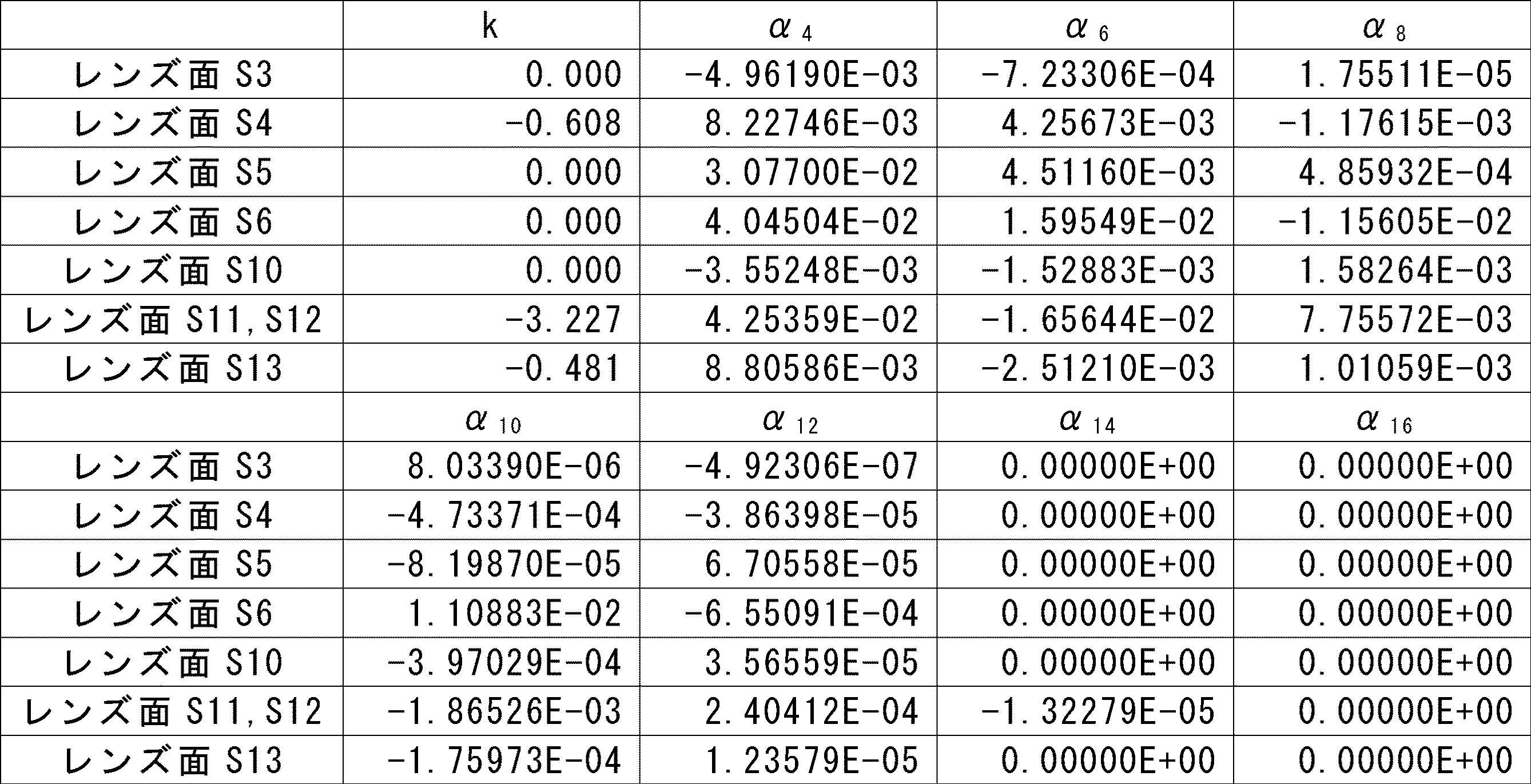
図10A及び図10Bに、実施例5の撮像レンズ系11における球面収差図(縦収差図)、像面湾曲図を示す。図10A及び図10Bに示す各収差図についての説明は図2A及び図2Bと同様であるため、その説明を省略する。
(実施例6)
図11は、実施例6に係るカメラモジュール10を示す断面図である。実施例6に係る撮像レンズ系11は、第3レンズL3の像側面S6が像側に凸面を向けた非球面形状を有し、第4レンズL4の物体側面S8が物体側に凹面を向けた球面形状を有すること以外は、実施例1と同様のレンズ構成を有するため、その説明を省略する。以下、実施例6に係る撮像レンズ系11の特性データについて説明する。
図11は、実施例6に係るカメラモジュール10を示す断面図である。実施例6に係る撮像レンズ系11は、第3レンズL3の像側面S6が像側に凸面を向けた非球面形状を有し、第4レンズL4の物体側面S8が物体側に凹面を向けた球面形状を有すること以外は、実施例1と同様のレンズ構成を有するため、その説明を省略する。以下、実施例6に係る撮像レンズ系11の特性データについて説明する。
表11に、実施例6に係る撮像レンズ系11の各レンズ面のレンズデータを示す。表11に示す項目は、表1と同様であるため、その説明を省略する。
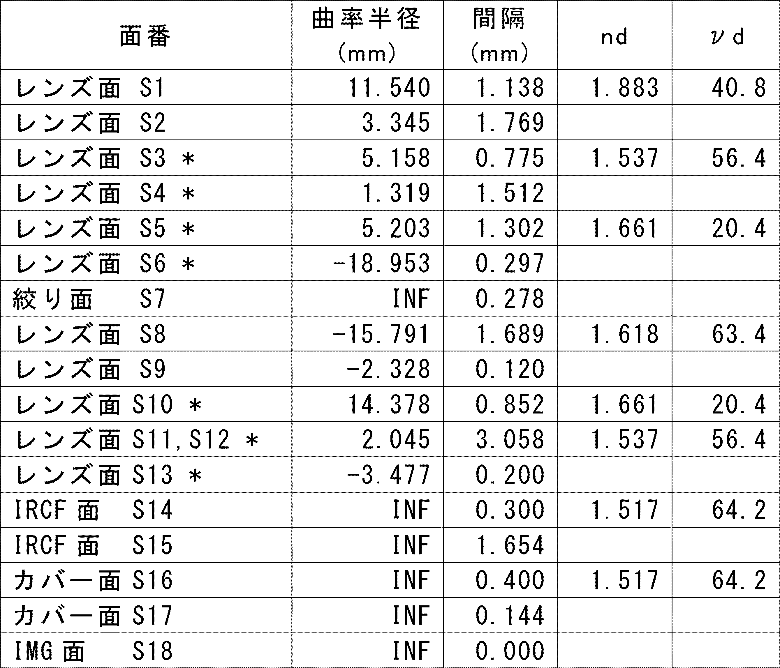
表12に、実施例6の撮像レンズ系11において、非球面とされたレンズ面の非球面形状を規定するための非球面係数を示す。表12において、レンズ面に採用される非球面形状は、実施例1と同様の式にて表される。
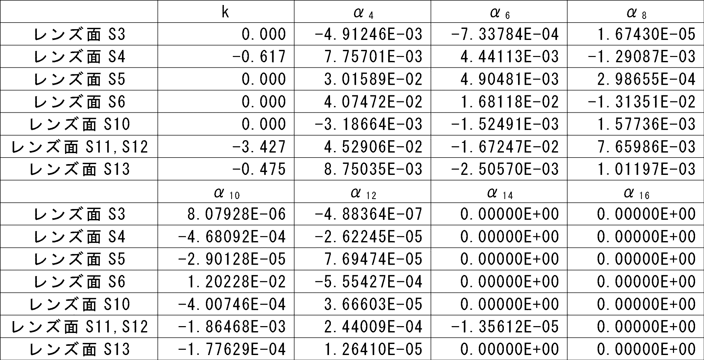
図12A及び図12Bに、実施例6の撮像レンズ系11における球面収差図(縦収差図)、像面湾曲図を示す。図12A及び図12Bに示す各収差図についての説明は図2A及び図2Bと同様であるため、その説明を省略する。
(実施例7)
図13は、実施例7に係るカメラモジュール10を示す断面図である。実施例7に係る撮像レンズ系11は、実施例1と同様のレンズ構成を有するため、その説明を省略する。以下、実施例7に係る撮像レンズ系11の特性データについて説明する。
図13は、実施例7に係るカメラモジュール10を示す断面図である。実施例7に係る撮像レンズ系11は、実施例1と同様のレンズ構成を有するため、その説明を省略する。以下、実施例7に係る撮像レンズ系11の特性データについて説明する。
表13に、実施例7に係る撮像レンズ系11の各レンズ面のレンズデータを示す。表13に示す項目は、表1と同様であるため、その説明を省略する。

表14に、実施例7の撮像レンズ系11において、非球面とされたレンズ面の非球面形状を規定するための非球面係数を示す。表14において、レンズ面に採用される非球面形状は、実施例1と同様の式にて表される。

図14A及び図14Bに、実施例7の撮像レンズ系11における球面収差図(縦収差図)、像面湾曲図を示す。図14A及び図14Bに示す各収差図についての説明は図2A及び図2Bと同様であるため、その説明を省略する。
表15に、撮像レンズ系11の光学全長TTL、第1レンズL1の焦点距離f1、第2レンズL2の焦点距離f2、第3レンズL3の焦点距離f3、第4レンズL4の焦点距離f4、第5レンズL5の焦点距離f5、第6レンズL6の焦点距離f6、撮像レンズ系11の光学系全体の焦点距離f、f1/fの値、f2/fの値、f3/fの値、f4/fの値、f5/fの値、f6/fの値、(L-STOP)/fの値、第1レンズL1と第2レンズL2の合成焦点距離f12、f12/fの値、SD1/IHの値を示している。表15において、焦点距離、光学全長の単位はいずれもmmである。また、表15に示す焦点距離、全長は、546.1nmの波長の光線を用いて計算した。
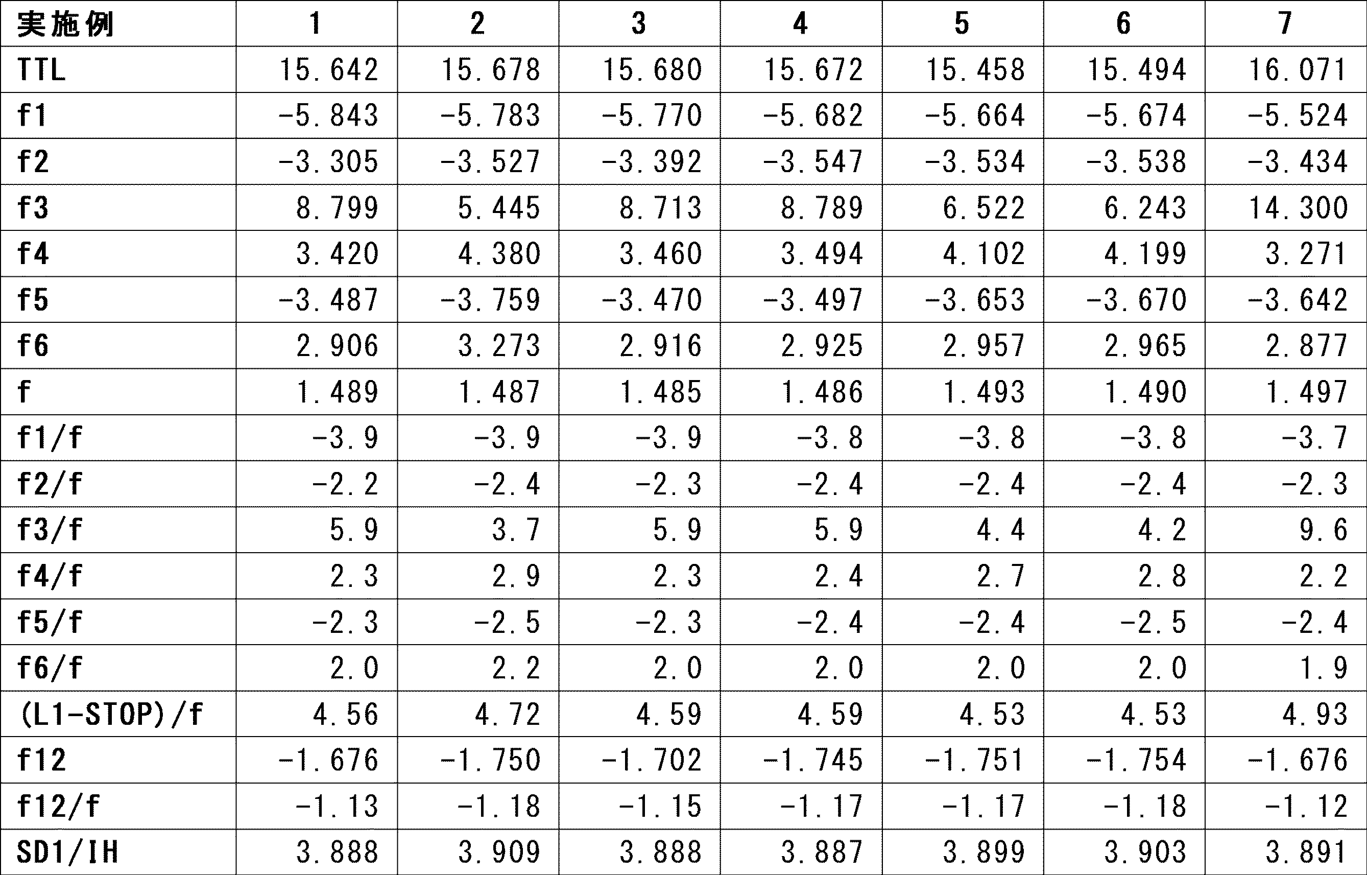
実施例1~7において、f1/fの値が条件式(2)を満足することにより、第1レンズL1の径を小さくすることができる。具体的には、実施例1~7において、SD1/IHの値は、3.887~3.909となっており、第1レンズL1の径を最大画角の像高に対して十分に小さくすることができている。また、第5レンズL5の物体側面が物体側に凸面を向けていることにより、周辺光量の低下を抑制することができる。
また、実施例1~7において、f12/fの値が上記の条件式(2)を満足することにより、第1レンズL1の小径化を図りつつ、第1レンズL1において発生する収差を抑制することができる。実際、実施例1~7において、図2A及び図2B、図4A及び図4B、図6A及び図6B、図8A及び図8B、図10A及び図10B、図12A及び図12B、図14A及び図14Bに示すように、諸収差を好適に低減できている。
また、実施例1~7において、f5/fの値が上記の条件式(3)を満たしていることにより、第1レンズL1において発生した収差を第5レンズL5において補正することができる。実際、実施例1~7において、図2A及び図2B、図4A及び図4B、図6A及び図6B、図8A及び図8B、図10A及び図10B、図12A及び図12B、図14A及び図14Bに示すように、諸収差を好適に低減できている。
また、実施例1~7において、(L1-STOP)/fの値が上記の条件式(4)を満たしていることにより、第1レンズL1の小径化を図りつつ、絞りSTOPより前群で発生する収差を抑制することができる。実際、実施例1~7において、図2A及び図2B、図4A及び図4B、図6A及び図6B、図8A及び図8B、図10A及び図10B、図12A及び図12B、図14A及び図14Bに示すように、諸収差を好適に低減できている。
また、カメラモジュール10が撮像レンズ系11を備え、撮像レンズ系11が小型化され、自動運転における画像認識に必要な十分な解像度を有することにより、カメラモジュール10の小型化及び高精度なセンシングを達成することができる。
(実施の形態3)
図15は、実施の形態1又は実施の形態2に係る撮像レンズ系11とこれを通じて集光される光を電気信号に変換する撮像素子12とを含む撮像装置50を備える車載システムが搭載される車両40の概略図である。図示のように、撮像装置50は車両40に搭載することができ、図15は、車両40における撮像装置50の搭載位置を例示する配置例である。車両40に搭載される撮像装置50は、車載カメラと呼ぶこともでき、車両40の種々の場所に設置することができる。例えば、第1の撮像装置50aは、車両40が走行する際の前方を監視するカメラとして、フロントバンパー又はその近傍に配置されてもよい。また、前方を監視する第2の撮像装置50bは、車両40の車室内のルームミラー(Inner Rearview Mirror)の近傍に配置されてもよい。第3の撮像装置50cは、運転者の運転状況を監視するカメラとしてダッシュボード上又はインスツルメントパネル内等に配置されてもよい。第4の撮像装置50dは、車両40の後方モニター用に車両40の後部に設置されてもよい。撮像装置50a、50bはフロントカメラと呼ぶことができる。第3の撮像装置50cは、インカメラと呼ぶことができる。第4の撮像装置50dはリアカメラと呼ぶことができる。撮像装置50は、これらに限られず、左後ろ側方を撮像する左サイドカメラおよび右後ろ側方を撮像する右サイドカメラ等、種々の位置に設置される撮像装置を含む。
図15は、実施の形態1又は実施の形態2に係る撮像レンズ系11とこれを通じて集光される光を電気信号に変換する撮像素子12とを含む撮像装置50を備える車載システムが搭載される車両40の概略図である。図示のように、撮像装置50は車両40に搭載することができ、図15は、車両40における撮像装置50の搭載位置を例示する配置例である。車両40に搭載される撮像装置50は、車載カメラと呼ぶこともでき、車両40の種々の場所に設置することができる。例えば、第1の撮像装置50aは、車両40が走行する際の前方を監視するカメラとして、フロントバンパー又はその近傍に配置されてもよい。また、前方を監視する第2の撮像装置50bは、車両40の車室内のルームミラー(Inner Rearview Mirror)の近傍に配置されてもよい。第3の撮像装置50cは、運転者の運転状況を監視するカメラとしてダッシュボード上又はインスツルメントパネル内等に配置されてもよい。第4の撮像装置50dは、車両40の後方モニター用に車両40の後部に設置されてもよい。撮像装置50a、50bはフロントカメラと呼ぶことができる。第3の撮像装置50cは、インカメラと呼ぶことができる。第4の撮像装置50dはリアカメラと呼ぶことができる。撮像装置50は、これらに限られず、左後ろ側方を撮像する左サイドカメラおよび右後ろ側方を撮像する右サイドカメラ等、種々の位置に設置される撮像装置を含む。
撮像装置50により撮像された画像の画像信号は、車両40内の情報処理装置42および/または表示装置43等に出力され得る。これらの情報処理装置42および表示装置43は、撮像装置50と共に車載システムを構成する。車両40内の情報処理装置42は、撮像装置50により取得される画像信号を処理し、前記撮像画像の中の各種対象物の認識を認識して運転者の運転を支援する装置を含む。また、情報処理装置42は、例えば、ナビゲーション装置、衝突被害軽減ブレーキ装置、車間距離制御装置、および、車線逸脱警報装置等を含むが、これらに限定されない。表示装置43は、情報処理装置42により処理されて出力される画像を表示するが、撮像装置50から直接に画像信号を受信することもできる。また、表示装置43は、液晶ディスプレイ(LCD:Liquid Crystal Display)、有機EL(Electro-Luminescence)ディスプレイ、および、無機ELディスプレイを採用し得るが、これらに限定されない。表示装置43は、リアカメラ等の運転者から視認しづらい位置の画像を撮像する撮像装置50から出力された画像信号を、運転者等の乗員に対して表示することができる。
図16には、図15の車載システムを構成する撮像装置50の構成が示される。図示のように、一実施の形態に係る撮像装置50は、制御部52と、記憶部54と、カメラモジュール10とを備える。
制御部52は、カメラモジュール10を制御するとともに、カメラモジュール10の撮像素子12から出力される電気信号を処理する。この制御部52は例えばプロセッサとして構成されてもよい。また、制御部52は1つ以上のプロセッサを含んでもよい。プロセッサは、特定のプログラムを読み込ませて特定の機能を実行する汎用のプロセッサ、および、特定の処理に特化した専用のプロセッサを含んでもよい。専用のプロセッサは、特定用途向けIC(Integrated Circuit)を含んでもよい。特定用途向けICは、ASIC(Application Specific Integrated Circuit)とも称される。プロセッサは、プログラマブルロジックデバイスを含んでもよい。プログラマブルロジックデバイスは、PLD(Programmable Logic Device)とも称される。PLDは、FPGA(Field-Programmable Gate Array)を含んでもよい。制御部52は、1つ以上のプロセッサが協働するSoC(System-on-a-Chip)、および、SiP(System In a Package)のいずれかであってもよい。
記憶部54は、撮像装置50の動作に係る各種情報又はパラメータを記憶する。記憶部54は、例えば半導体メモリ等で構成されてもよい。記憶部54は、制御部52のワークメモリとして機能してもよい。記憶部54は、撮像画像を記憶してもよい。記憶部54は、制御部52が撮像画像に基づく検出処理を行なうための各種パラメータ等を記憶してもよい。記憶部54は制御部52に含まれてもよい。
前述したように、カメラモジュール10は、撮像レンズ系11を介して結像する被写体像を撮像素子12で撮像し、撮像した画像を出力する。カメラモジュール10で撮像された画像は、撮像画像とも称される。
撮像素子12は、例えば、CMOS(Complementary Metal Oxide Semiconductor)イメージセンサ又はCCD(Charge Coupled Device)等で構成されてよい。撮像素子12は、複数の画素が並ぶ撮像面を有する。各画素は、入射した光量に応じて電流又は電圧で特定される信号を出力する。各画素が出力する信号は、撮像データとも称される。
撮像データは、全ての画素についてカメラモジュール10で読み出され、撮像画像として制御部52に取り込まれてもよい。全ての画素について読み出された撮像画像は、最大撮像画像とも称される。撮像データは、一部の画素についてカメラモジュール10で読み出され、撮像画像として取り込まれてもよい。言い換えれば、撮像データは、所定の取り込み範囲の画素から読み出されてもよい。所定の取り込み範囲の画素から読み出された撮像データは、撮像画像として取り込まれてもよい。所定の取り込み範囲は、制御部52によって設定されてもよい。カメラモジュール10は、制御部52から所定の取り込み範囲を取得してもよい。撮像素子12は、撮像レンズ系11を介して結像する被写体像のうち所定の取り込み範囲の画像を撮像してもよい。
なお、本発明は上記実施例に限られたものではなく、趣旨を逸脱しない範囲で適宜変更することが可能である。例えば、本発明の撮像レンズ系の用途は、車載カメラや監視カメラに限定されるものではなく、携帯電話等の小型電子機器に搭載する等の他の用途にも用いることができる。
この出願は、2022年7月15日に出願された日本出願特願2022-113782を基礎とする優先権を主張し、その開示の全てをここに取り込む。
小型化された撮像レンズ系、カメラモジュール、車載システム、移動体を提供することができる。
10 カメラモジュール
11 撮像レンズ系
12 撮像素子
40 車両(移動体)
42 情報処理装置(処理装置)
43 表示装置(出力装置)
50 撮像装置
52 制御部
L1 第1レンズ
L2 第2レンズ
L3 第3レンズ
L4 第4レンズ
L5 第5レンズ
L6 第6レンズ
STOP 絞り
Gf 前群
Gr 後群
IRCF 赤外線カットフィルタ
IMG 結像面
OA 光軸
11 撮像レンズ系
12 撮像素子
40 車両(移動体)
42 情報処理装置(処理装置)
43 表示装置(出力装置)
50 撮像装置
52 制御部
L1 第1レンズ
L2 第2レンズ
L3 第3レンズ
L4 第4レンズ
L5 第5レンズ
L6 第6レンズ
STOP 絞り
Gf 前群
Gr 後群
IRCF 赤外線カットフィルタ
IMG 結像面
OA 光軸
Claims (14)
- 物体側から像側に向かって順に、物体側面が物体側に凸面を向けた負のパワーを有する第1レンズ、物体側面が物体側に凸面を向けた負のパワーを有する第2レンズ、物体側面が物体側に凸面を向けた正のパワーを有する第3レンズ、絞り、像側面が像側に凸面を向けた正のパワーを有する第4レンズ、物体側面が物体側に凸面を向けた負のパワーを有する第5レンズ、正のパワーを有する第6レンズ、からなり、
前記第5レンズと前記第6レンズとは接合レンズを構成し、
前記第1レンズの焦点距離をf1、光学系全体の焦点距離をfと定義したときに、以下の条件式(1)を満足することを特徴とする、
撮像レンズ系。
-4.0<f1/f・・・(1) - 前記第1レンズと前記第2レンズの合成焦点距離をf12、光学系全体の焦点距離をfと定義したときに、以下の条件式(2)を満足することを特徴とする、請求項1に記載の撮像レンズ系。
-1.2<f12/f<-1.1・・・(2) - 前記第5レンズの焦点距離をf5、光学系全体の焦点距離をfと定義したときに、以下の条件式(3)を満足することを特徴とする、請求項1に記載の撮像レンズ系。
f5/f<-2.2・・・(3) - 前記第5レンズの焦点距離をf5、光学系全体の焦点距離をfと定義したときに、以下の条件式(3)を満足することを特徴とする、請求項2に記載の撮像レンズ系。
f5/f<-2.2・・・(3) - 前記第1レンズの物体側面と前記絞りとの間の中心光軸における距離をL1-STOP、光学系全体の焦点距離をfと定義したときに、以下の式(4)を満足する、請求項1に記載の撮像レンズ系。
4.0<(L1-STOP)/f<5.5・・・(4) - 前記第1レンズの物体側面と前記絞りとの間の中心光軸における距離をL1-STOP、光学系全体の焦点距離をfと定義したときに、以下の式(4)を満足する、請求項2に記載の撮像レンズ系。
4.0<(L1-STOP)/f<5.5・・・(4) - 前記第1レンズの物体側面と前記絞りとの間の中心光軸における距離をL1-STOP、光学系全体の焦点距離をfと定義したときに、以下の式(4)を満足する、請求項3に記載の撮像レンズ系。
4.0<(L1-STOP)/f<5.5・・・(4) - 前記第1レンズの有効径をSD1、最大画角の像高をIHと定義したときに、以下の式(5)を満足する、請求項1に記載の撮像レンズ系。
SD1/IH<4.0・・・(5) - 前記第1レンズの有効径をSD1、最大画角の像高をIHと定義したときに、以下の式(5)を満足する、請求項2に記載の撮像レンズ系。
SD1/IH<4.0・・・(5) - 前記第1レンズの有効径をSD1、最大画角の像高をIHと定義したときに、以下の式(5)を満足する、請求項3に記載の撮像レンズ系。
SD1/IH<4.0・・・(5) - 前記第1レンズの有効径をSD1、最大画角の像高をIHと定義したときに、以下の式(5)を満足する、請求項5に記載の撮像レンズ系。
SD1/IH<4.0・・・(5) - 請求項1~11の何れか一項に記載の撮像レンズ系と、前記撮像レンズ系を通じて集光される光を電気信号に変換する撮像素子とを備えることを特徴とするカメラモジュール。
- 車両に搭載される車載システムであって、
請求項12に記載のカメラモジュールと、
前記カメラモジュールの前記撮像素子から出力される撮像画像を処理して、前記撮像画像の中の対象物の認識を行う情報処理装置と、
を備えることを特徴とする車載システム。 - 請求項13に記載の車載システムを搭載した移動体であって、
前記車載システムは、乗員への情報を出力する出力装置をさらに備え、
前記情報処理装置は前記対象物の認識情報を前記出力装置に出力するように構成されていることを特徴とする移動体。
Applications Claiming Priority (2)
| Application Number | Priority Date | Filing Date | Title |
|---|---|---|---|
| JP2022113782A JP2024011616A (ja) | 2022-07-15 | 2022-07-15 | 撮像レンズ系、カメラモジュール、車載システム、移動体 |
| JP2022-113782 | 2022-07-15 |
Publications (1)
| Publication Number | Publication Date |
|---|---|
| WO2024014189A1 true WO2024014189A1 (ja) | 2024-01-18 |
Family
ID=89536576
Family Applications (1)
| Application Number | Title | Priority Date | Filing Date |
|---|---|---|---|
| PCT/JP2023/021111 Ceased WO2024014189A1 (ja) | 2022-07-15 | 2023-06-07 | 撮像レンズ系、カメラモジュール、車載システム、移動体 |
Country Status (2)
| Country | Link |
|---|---|
| JP (1) | JP2024011616A (ja) |
| WO (1) | WO2024014189A1 (ja) |
Citations (5)
| Publication number | Priority date | Publication date | Assignee | Title |
|---|---|---|---|---|
| WO2012127826A1 (ja) * | 2011-03-18 | 2012-09-27 | 富士フイルム株式会社 | 撮像レンズおよび撮像装置 |
| US20150277088A1 (en) * | 2014-04-01 | 2015-10-01 | Sintai Optical (Shenzhen) Co., Ltd. | Wide-angle lens assembly |
| US20170153418A1 (en) * | 2015-12-01 | 2017-06-01 | Calin Technology Co., Ltd. | Wide angle lens |
| JP2017191160A (ja) * | 2016-04-12 | 2017-10-19 | キヤノン株式会社 | 光学系及びそれを有する撮像装置 |
| JP2019089394A (ja) * | 2017-11-13 | 2019-06-13 | 矢崎総業株式会社 | 自動運転時情報伝達方法および車両用情報提示装置 |
-
2022
- 2022-07-15 JP JP2022113782A patent/JP2024011616A/ja active Pending
-
2023
- 2023-06-07 WO PCT/JP2023/021111 patent/WO2024014189A1/ja not_active Ceased
Patent Citations (5)
| Publication number | Priority date | Publication date | Assignee | Title |
|---|---|---|---|---|
| WO2012127826A1 (ja) * | 2011-03-18 | 2012-09-27 | 富士フイルム株式会社 | 撮像レンズおよび撮像装置 |
| US20150277088A1 (en) * | 2014-04-01 | 2015-10-01 | Sintai Optical (Shenzhen) Co., Ltd. | Wide-angle lens assembly |
| US20170153418A1 (en) * | 2015-12-01 | 2017-06-01 | Calin Technology Co., Ltd. | Wide angle lens |
| JP2017191160A (ja) * | 2016-04-12 | 2017-10-19 | キヤノン株式会社 | 光学系及びそれを有する撮像装置 |
| JP2019089394A (ja) * | 2017-11-13 | 2019-06-13 | 矢崎総業株式会社 | 自動運転時情報伝達方法および車両用情報提示装置 |
Also Published As
| Publication number | Publication date |
|---|---|
| JP2024011616A (ja) | 2024-01-25 |
Similar Documents
| Publication | Publication Date | Title |
|---|---|---|
| JP7749352B2 (ja) | 撮像レンズ系、カメラモジュール、車載システム、移動体 | |
| US20250155675A1 (en) | Imaging lens system, camera module, in-vehicle system, and vehicle | |
| JP2011048334A (ja) | 撮像レンズおよび撮像装置 | |
| JP7827575B2 (ja) | 撮像レンズ系、カメラモジュール、車載システム、移動体 | |
| WO2024147254A1 (ja) | 撮像レンズ系、カメラモジュール、車載システム、移動体 | |
| JP2024011616A (ja) | 撮像レンズ系、カメラモジュール、車載システム、移動体 | |
| WO2025028418A1 (ja) | 撮像レンズ系、カメラモジュール、車載システム、移動体 | |
| WO2025028419A1 (ja) | 撮像レンズ系、カメラモジュール、車載システム、移動体 | |
| US20260029620A1 (en) | Imaging lens system, camera module, in-vehicle system, and vehicle | |
| WO2026014117A1 (ja) | 撮像レンズ系、カメラモジュール、車載システム、移動体 | |
| WO2026053706A1 (ja) | 撮像レンズ系、カメラモジュール、車載システム、移動体 | |
| JP2023111409A (ja) | 撮像レンズ系、及びそれを用いたカメラモジュール、車載システム、移動体 | |
| JP2025115843A (ja) | 撮像レンズ系、カメラモジュール、車載システム、移動体 | |
| JP2026080839A (ja) | 撮像レンズ系、カメラモジュール、車載システム、移動体 | |
| WO2026075062A1 (ja) | 撮像レンズ系、カメラモジュール、車載システム、移動体 | |
| JP2026071057A (ja) | 撮像レンズ系、カメラモジュール、車載システム、移動体 | |
| WO2025134818A1 (ja) | 撮像レンズ系、カメラモジュール、車載システム、移動体 | |
| JP2023107491A (ja) | 撮像レンズ系、カメラモジュール、車載システム、移動体 | |
| JP2026083777A (ja) | 撮像レンズ系、カメラモジュール、車載システム、移動体 | |
| JP2026019471A (ja) | 撮像レンズ系、カメラモジュール、車載システム、移動体 | |
| JP2025020688A (ja) | 撮像レンズ系、カメラモジュール、車載システム、移動体 | |
| JP2025039348A (ja) | 撮像レンズ系、カメラモジュール、車載システム、移動体 | |
| JP2024101705A (ja) | 撮像レンズ系、カメラモジュール、車載システム、移動体 | |
| JP2026042576A (ja) | 撮像レンズ系及びこれを備えるカメラモジュール、撮像装置、車載システム、移動体 | |
| JP2026077505A (ja) | 撮像レンズ系及びこれを備えるカメラモジュール、撮像装置、車載システム、移動体 |
Legal Events
| Date | Code | Title | Description |
|---|---|---|---|
| 121 | Ep: the epo has been informed by wipo that ep was designated in this application |
Ref document number: 23839365 Country of ref document: EP Kind code of ref document: A1 |
|
| NENP | Non-entry into the national phase |
Ref country code: DE |
|
| 122 | Ep: pct application non-entry in european phase |
Ref document number: 23839365 Country of ref document: EP Kind code of ref document: A1 |