WO2024014153A1 - 播種機および播種方法 - Google Patents
播種機および播種方法 Download PDFInfo
- Publication number
- WO2024014153A1 WO2024014153A1 PCT/JP2023/020242 JP2023020242W WO2024014153A1 WO 2024014153 A1 WO2024014153 A1 WO 2024014153A1 JP 2023020242 W JP2023020242 W JP 2023020242W WO 2024014153 A1 WO2024014153 A1 WO 2024014153A1
- Authority
- WO
- WIPO (PCT)
- Prior art keywords
- seeding machine
- detection device
- position detection
- field
- seeds
- Prior art date
- Legal status (The legal status is an assumption and is not a legal conclusion. Google has not performed a legal analysis and makes no representation as to the accuracy of the status listed.)
- Ceased
Links
Images








Classifications
-
- A—HUMAN NECESSITIES
- A01—AGRICULTURE; FORESTRY; ANIMAL HUSBANDRY; HUNTING; TRAPPING; FISHING
- A01B—SOIL WORKING IN AGRICULTURE OR FORESTRY; PARTS, DETAILS, OR ACCESSORIES OF AGRICULTURAL MACHINES OR IMPLEMENTS, IN GENERAL
- A01B69/00—Steering of agricultural machines or implements; Guiding agricultural machines or implements on a desired track
-
- A—HUMAN NECESSITIES
- A01—AGRICULTURE; FORESTRY; ANIMAL HUSBANDRY; HUNTING; TRAPPING; FISHING
- A01C—PLANTING; SOWING; FERTILISING
- A01C1/00—Apparatus, or methods of use thereof, for testing or treating seed, roots, or the like, prior to sowing or planting
- A01C1/06—Coating or dressing seed
-
- A—HUMAN NECESSITIES
- A01—AGRICULTURE; FORESTRY; ANIMAL HUSBANDRY; HUNTING; TRAPPING; FISHING
- A01C—PLANTING; SOWING; FERTILISING
- A01C7/00—Sowing
- A01C7/08—Broadcast seeders; Seeders depositing seeds in rows
Definitions
- the present invention relates to a seeding machine and a seeding method for sowing seeds in a field, and particularly relates to a seeding machine and a seeding method for sowing seeds at regular intervals in a flooded field.
- Patent Document 1 describes an example of a method for producing iron powder-coated rice seeds used in the flooded direct sowing method in which seeds are directly sown in a flooded field.
- the iron-powder-coated rice seeds are composed of rice seeds coated with high-density iron powder, so they tend to sink in water. Therefore, in the flooded direct sowing method, the use of the seeds described in Patent Document 1 can prevent or suppress floating or flowing out of seeds in a flooded paddy field, and can also prevent or suppress bird damage. It is attracting attention because of its advantages such as the ability to
- Patent Document 2 describes an example of a flooded direct sowing machine that sows seeds in a flooded field, and the flooded direct sowing machine is driven by driving in the field, causing damage to the power transmission part due to mud scattered from the field. Constructed to prevent dirt.
- Patent Document 3 describes a seeding machine that can control the burying depth of seeds in the surface of a flooded rice field.
- Patent Document 4 describes a seeding machine equipped with a puddling rotary device called a harrow device that is capable of direct sowing in water.
- Patent Document 5 describes an autonomous driving system for a work vehicle that acquires position information of a work vehicle such as a rice transplanter based on radio waves received from a positioning satellite of GNSS (Global Navigation Satellite System) and uses the position information. has been done.
- GNSS Global Navigation Satellite System
- the autonomous driving system described in Patent Document 5 is installed on a seeding machine that sows seeds in a flooded field, and if a situation occurs in which signals from a positioning satellite cannot be received, the sowing If the position of the machine cannot be determined, it may end up sowing seeds in areas that have already been sown, or may leave areas that have not been sown. As a result, it may not be possible to sow seeds regularly throughout the field.
- the present invention has been made to solve the above problems, and provides a seeding machine and a seeding method that can easily determine the running position and sow seeds in a predetermined position even in a flooded field.
- the purpose is to provide
- a seeding machine in which a seeder for sowing seeds in the field is provided on a base supported by wheels configured to be able to travel through a flooded field, and the seeding machine is provided with a seeder for sowing seeds in the field by the wheels. At least one of a rut, a waterway pre-formed in the field, a linear groove pre-formed in the field, and a flexible linear body stretched in a straight line in advance in the field
- a seeding machine comprising: one guide, and a position detection device provided on the base that engages with the guide.
- the position detection device is configured to detect at least one of ruts formed in the field by the wheels, waterways formed in advance in the field, and linear grooves formed in advance in the field.
- the position detecting device is configured in a rod shape, and is configured to support the position detecting device with a predetermined distance between the position detecting device and the base body in the left-right direction.
- the position detection device is guided by a flexible linear body stretched in advance in a straight line on the field, and is engaged with the linear body so as to be able to move relative to the linear body, [1] Seeding machine described in. [5]
- the position detection device includes a slit configured to engage the linear body in a relatively movable manner, and a plate thickness of the position detection device configured to engage the linear body in a relatively movable manner.
- the seeding machine according to [4] which has one of the holes formed to penetrate in the direction.
- Any of the seeding machines [7] [1] to [5] according to [1] further comprising a position information acquisition device that acquires position information based on a signal acquired from a satellite positioning system.
- a sowing method of sowing seeds using the described sowing machine [8] The seeding method according to [7], wherein the seed has a surface coated with a seed coating agent containing a metal material and has a specific gravity of 1.2 g/cm 3 or more and 4.0 g/cm 3 or less.
- ruts formed by the wheels of a seeding machine in a field in a flooded state, ruts formed by the wheels of a seeding machine, water channels previously formed in the field, linear grooves formed in advance in the field, and linear grooves formed in the field.
- a position detection device is engaged with the guide.
- the position detection device moves with the seeding machine while maintaining a substantially constant distance from the guide, so it does not deform in the left or right direction with respect to the direction of travel. It never oscillates.
- such deformation or rocking is small compared to the case where the seeding machine moves in the left-right direction so as to approach and move away from the guide.
- the distance between the guide and the position detection device changes, and the position detection device deforms in the left-right direction accordingly. or oscillate. Therefore, it is possible to grasp the current position of the seeding machine relative to the guide in the left-right direction based on the amount of deformation and the magnitude of the swing of the position detection device. That is, it can be determined whether the vehicle is traveling along the guide or not.
- the linear body When the seeding machine travels using the linear body as a guide, when the seeding machine moves in the left and right directions with respect to the traveling direction, the linear body is bent at the engagement portion between the linear body and the position detection device.
- the position of the seeding machine relative to the linear body can be determined by the bending angle of the linear body.
- the seeding machine can be run along the guide and seeds can be sown at a predetermined position.
- the position detection device is provided on the base of the seeding machine, it is possible to easily grasp the traveling position of the seeding machine in the left-right direction with respect to the guide and to easily correct the traveling position of the seeding machine.
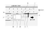
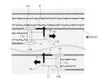
- FIG. 2 is a side view of the seeding machine shown in FIG. 1.
- FIG. It is a figure for demonstrating the bending deformation of the position detection device accompanying the movement of the seeding machine in the left-right direction.
- 5 is a side view of the seeding machine shown in FIG. 4.
- FIG. It is a figure showing an example of the seeding machine concerning a 3rd embodiment of the present invention.
- FIG. 7 is a side view of the seeding machine shown in FIG. 6. It is a figure showing an example of the seeding machine concerning a 4th embodiment of the present invention.
- FIG. 9 is a side view of the seeding machine shown in FIG. 8.
- FIG. It is a figure showing an example of the seeding machine concerning a 5th embodiment of the present invention.
- FIG. 11 is a side view of the seeding machine shown in FIG. 10. It is a figure showing an example of the seeding machine concerning a 3rd embodiment of the present invention.
- FIG. 13 is a side view of the seeding machine shown in FIG. 12. It is a diagram for explaining a state in which seeds are regularly sown throughout the field. It is a figure for explaining the state where seeds are not sown regularly throughout the field. It is a figure showing an example of the seeding machine concerning a 7th embodiment of the present invention.
- FIG. 17 is a side view of the seeding machine shown in FIG. 16. It is a diagram showing an example of the configuration of a mobile terminal.
- the seeding machine according to the embodiment of the present invention is capable of forming groove-like ruts and waterways (clear culverts) formed in a field in a flooded state, streaks and linear grooves formed in the field by conventionally known markers, and straight lines in the field. It is configured to run using a flexible linear body stretched in advance as a guide for the running position in the field. In other words, it is configured to run as a guide. Further, the seeding machine according to the embodiment of the present invention is configured to sow seeds while traveling along a guide in a flooded field.
- the above-mentioned seeding machine includes wheels that are configured to be able to travel through a field in a flooded state, a base body that is supported by the wheels, and a base body that sows seeds in the field along the direction of travel.
- the main components include a seeder configured as described above, and a position detection device that detects the running position of the seeding machine in the left and right direction with respect to the guide. That is, the seeding machine according to the embodiment of the present invention is configured to sow seeds by traveling while detecting the current traveling position with respect to the guide in the left and right directions when traveling along the guide in a field in a flooded state. has been done.
- the seeding machine mentioned above may be either a power type equipped with a driving force source that outputs motive power for running, or a manual type without a driving force source.
- the wheels configured to be able to travel on the flooded fields as described above, as long as they can travel on the rice fields.
- FIG. 1 is a diagram showing an example of a seeding machine according to a first embodiment of the present invention.
- the seeding machine 1 shown in FIG. 1 is a manual four-wheel type seeding machine 1, and left and right front wheels 3R and 3L are provided on the front side of the base 2 in the direction of travel of the sowing machine 1.
- Left and right rear wheels 4R and 4L are provided on the rear side of the vehicle 2.
- a base body 2 is supported by these wheels 3R, 3L, 4R, and 4L, and a seeder 5 is provided on the base body 2.
- the seeding machine 1 may have a driving force source that generates driving force for traveling.
- a steering device (not shown) may be provided at the rear of the seeding machine 1, and the direction of movement of the seeding machine 1 may be changed by an operator operating the steering device.
- a special steering device such as a steering wheel is not essential.
- the seeder 5 may be a conventionally known seeder.
- the seeder 5 operates in conjunction with the rotation of the front wheels 3R, 3L and the rear wheels 4R, 4L when the seeding machine 1 travels in the field, and performs spot sowing, row sowing, and scattering.
- the configuration is configured to perform either one of them.
- the seeder 5 includes, for example, a cylindrical container (not shown) filled with seeds, and the seeds are dropped at regular intervals through holes formed through the container in the thickness direction. It may be a drum seeder configured to sow seeds.
- the seeder 5 may be a broadcaster that includes a seed storage section (not shown) and sows seeds by flipping the seeds supplied from the storage section by rotating a rotating body (not shown).
- the seeder 5 may be a seeder that includes a measuring device (not shown) and is configured to sow seeds measured by the measuring device in a field.
- the seeder 5 may be a seeder configured to sow seeds in a field using magnetic force, centrifugal force, or the like.
- the seeder 5 may be a seeder that is equipped with a motor (not shown) and configured so that the timing of sowing can be freely controlled by the motor without being interlocked with the wheels 3R, 3L, 4R, and 4L.
- the seeder 5 may be configured to sow seeds in the field in conjunction with the running of the seeder 1 when the seeder 1 runs in the field.
- the number of rows for spot sowing and row sowing is shown as two in FIG. 1 to simplify the explanation, but it is of course possible to have an apparatus configuration with more than two rows.
- articles 3 to 20 are examples of articles 3 to 20. If there is no problem in operation, it is possible to exceed 20 articles and is within the scope of the present invention.
- the width of the sowing there is no particular restriction on the width of the sowing, and it may be about 0.1 m to 10 m if there is no problem with the work.
- a position detection device 6 configured to engage with the above-mentioned guide is provided on the front side of the base body 2 in the direction in which the seeding machine 1 moves.
- the position detection device 6 has a rod-like configuration, and is supported by the base body 2 via a support mechanism.
- the support mechanism includes a first arm part 7 that projects forward of the seeding machine 1 from approximately the center of the front end of the base body 2, and a second arm part 8 that extends to the left from the tip of the first arm part. There is.
- the protruding length of the first arm part 7 from the front end of the base body 2 in the traveling direction is such that one end of the first arm part 7 (hereinafter referred to as the tip of the first arm part 7) is connected to the front wheel 3R. , 3L.
- the other end in the length direction of the first arm portion 7 is integrally connected to the base body 2 by a connecting means.
- the connection means may be any conventional connection means, such as adhesive, welding, riveting, bolting, etc.
- One end in the length direction of the second arm 8 is connected to the distal end of the first arm 7 so as to be rotatable about the axis of the first arm 7 .
- the position detection device 6 When the operator is positioned behind the seeding machine 1 to control the direction of movement of the seeding machine 1, placing the position detection device 6 on the front side of the seeding machine 1 makes it easier to grasp the running position of the seeding machine 1. preferable. However, as long as the running position of the seeding machine 1 can be grasped, the position detection device 6 may be installed anywhere. For example, even if the position detection device 6 is installed behind the operator, if it is configured so that the amount of deformation of the position detection device 6, which will be described later, can be grasped using a mirror, camera, position sensor, etc. , are within the scope of the present invention.
- the second arm portion 8 extends to the left (upper side in FIG. 1) with respect to the traveling direction of the seeding machine 1, that is, toward the rut side that serves as a guide.
- the length of the second arm portion 8 in the left-right direction with respect to the traveling direction of the seeding machine 1 or in the width direction of the seeding machine 1 is the length of the second arm portion 8 in the left-right direction ( The length is set such that the front left wheel 3L and the rear left wheel 4L are located at approximately the same position.
- the second arm portion 8 may have a length that is greater than or equal to the above-mentioned set length as long as the traveling position can be determined.
- the length of the second arm section 8 is such that the position detection device 6 attached to the second arm section 8 can engage with the guide when traveling on ruts, lines, etc. as a guide. It is sufficient if the length is set so that the position detection device 6 can reach it.
- a rod-shaped position detection device 6 is provided at the tip of the second arm portion 8 and extends in the traveling direction, and is rotatable about the axis of the second arm portion 8 as the center axis of rotation. and are connected so as to be selectively fixable.
- one end of the position detection device 6 is connected to the tip of the second arm 8 via a joint that can rotate around the arm 8.
- the other end (hereinafter referred to as the tip) of the position detection device 6 detects the position in the vertical direction of the seeding machine 1 so as to engage with the ruts, stripes, waterways, grooves, etc. that function as guides. It is located below one end of the device 6.
- the position detection device 6 is attached to the second arm portion 8 so as to be inclined downward from the front toward the rear in the traveling direction.
- the shape of the tip of the position detection device 6 is configured to fit inside a rut, streak, waterway, groove, or the like.
- the rigidity of the position detection device 6 and the rigidity of each arm portion 7, 8 will be explained.
- the rigidity of the position detection device 6 is determined based on the rigidity of the sowing machine 1 in the left-right direction when the sowing machine 1 moves in the left-right direction with the tip of the position detection device 6 engaged with the guide.
- the rigidity is set so that it flexes and deforms in the left and right directions depending on the amount.
- each of the arm parts 7 and 8, which is a support mechanism supports the position detection device 6, the rigidity of each arm part 7 and 8 is set higher than the rigidity of the position detection device 6. ing.
- rigidity means difficulty in deformation.
- the material constituting the position detection device 6 examples include natural materials such as bamboo, reed, and wood, synthetic resin materials, and metal wires. Moreover, since the tip of the position detection device 6 moves along the guide while being engaged with the guide, the position detection device 6 may be made of a material with excellent wear resistance and slidability. Materials with excellent wear resistance and sliding properties include, for example, polyolefins such as ultra-high molecular weight polyethylene, polyoxymethylene, polyamide, synthetic resin materials containing fluorine resins such as PTFE, polyphenylene sulfide, polyether ether ketone, and polyester. , polyurethane, phenolic resin, and composite materials thereof.
- the position detection device 6 may be made of any of the above-mentioned materials, but natural materials such as bamboo, reed, and wood are preferred in terms of ease of availability.
- the metal wire may be anything that can be bent and deformed, such as a piano wire.
- first arm portion 7 and the second arm portion 8 examples include metal materials, wood, and resin materials.
- first arm section 7 and the second arm section 8 may be made of a material that is less susceptible to bending deformation than the material that constitutes the position detection device 6.
- Examples of the guide include groove-like ruts and waterways (culverts) formed in a field in a flooded state, and lines formed in a field using a conventionally known marker. It is preferable to form them after plowing a flooded field and waiting for the soil surface to harden to some extent. By doing so, the strength of the grooves, ruts, waterways, etc. can be increased to a certain extent, making it easier to trace with the position detection device 6. In other words, it becomes easier to maintain the state of engagement with the guide. Furthermore, drainage channels can be formed in the field as designed.
- a waterway may be formed.
- Other examples of guides include ridges, rails, and the like.
- a flexible linear body such as a rope, that is stretched in a straight line on the field in advance can be used.
- These guides are preferably located in the vicinity of the seeding machine 1, but may be located at a distance of more than the wheel width of the seeding machine 1.
- the guide may be not only the ruts traveled just before, but also the ruts and grooves traveled two, three, or more times before, and the scope of the present invention falls within the scope of the present invention. It is within.
- the position detection device 15 may be a movable mechanism so that the seeding machine can travel multiple times in a state where the position information can be confirmed even when the linear body is fixed, and within the scope of the present invention. be.
- grooves, ruts, waterways, etc. formed on the soil surface of the field are preferably linear, but the shapes of the grooves, ruts, waterways, etc. are not limited.
- the strength of grooves, ruts, waterways, etc. refers to their resistance to breakage.
- the seeds used in the embodiment of the present invention are preferably rice.
- the variety of rice is not limited, and any of Japonica rice, Indica rice, and Javanica rice can be applied. Since rice is often cultivated in paddy fields in hot and humid regions, the effects of the present invention can be exerted. Moreover, instead of rice, any seeds that are sown in a flooded state are preferably applied.
- the above-mentioned seeds are preferably seeds that are coated with a seed coating agent and have a higher specific gravity than dry seeds that are not coated with the seed coating agent (hereinafter referred to as coated seeds). This is because the covered seeds can be submerged in water in a flooded field, and the washed away of the covered seeds can be suppressed. Seed coating agents that increase the specific gravity of seeds are not limited, but seed coating agents that have a higher specific gravity than seeds are preferred.
- iron (Fe), silicon (Si), magnesium (Mg), calcium (Ca), aluminum (Al), manganese (Mn), copper (Cu), zinc (Zn), phosphorus (P), molybdenum (Mo Seed coating agents containing metallic materials or high specific gravity materials such as ) are preferred.
- the seed coating agent from the viewpoint of the effect of increasing the specific gravity of the seeds and the effect of the seed coating agent on the soil, it is preferable to use one mainly containing iron materials.
- coated seeds referred to as iron-coated seeds, can be preferably applied.
- the iron material include iron oxide, iron powder, and slag.
- the seed coating agent may be a seed coating agent that is a combination of one or more of the metal materials or high specific gravity materials mentioned above.
- the specific gravity of dry seeds that are not coated with a seed coating agent is approximately 1.1 g/ cm3 , and the specific gravity of iron-coated seeds is lower than that of dry seeds that are not coated with a seed coating agent. It is preferably higher than 0.1 g/cm 3 .
- the specific gravity of the iron-coated seeds is preferably 1.2 g/cm 3 or more, more preferably 1.3 g/cm 3 or more. This is to suppress burying in mud and position the covered seeds near the soil surface when the seeds are sown in a flooded field, as well as to prevent the covered seeds from being washed away from the field. Moreover, this allows the iron-coated seeds to germinate and grow at the sown location.
- the upper limit of the specific gravity of the iron-coated seeds is not limited, it is preferably 4.0 g/cm 3 or less. This is to suppress an increase in material costs due to an increase in the amount of seed coating agent used, as well as to suppress burying of the coated seeds in mud due to an increase in the specific gravity of the seeds.
- the method of coating seeds with the above-mentioned iron material is not limited.
- ⁇ Iron Coating Direct Sowing Manual 2010 (edited by the National Agriculture and Food Research Organization, Kinki-Chugoku-Shikoku Agricultural Research Center)'', there are many methods that have been known in the past, including manual coating. Any method may be used, such as using a mixer.
- a stirring blade mixer or a container rotating mixer can be used as the mixer.
- a concrete mixer with a stirring blade removed can also be preferably used as a mixer.
- the stirring vane type mixer include Henschel mixer, concrete mixer, and the like.
- the container-rotating mixer include a V-type mixer, a double cone mixer, an inclined rotating pan-type mixer, and a rotary hoe-type mixer.
- a specific method for coating seeds with a seed coating agent includes seeds, iron powder and iron oxide powder as iron materials, calcined gypsum and polyvinyl alcohol resin as binders, silica gel as additives, seed treatment agents, and fertilizers. Ingredients are appropriately added to a mixer and mixed. Another method may include a method in which seeds are coated with water or a water-based treatment liquid while being sprayed. A similar method can be applied when covering seeds with other materials having a higher specific gravity than the seeds. Examples of other materials include materials containing iron oxide, slag, calcium, and the like. In addition, formulations such as hardening with rust or hardening with a binder such as resin or lime can also be applied.
- the direction of the seeding machine 1 is reversed by a steering device (not shown) and turned back.
- the position where the seeding machine 1 is moved is shifted by the width of the seeding machine 1 with respect to the travel locus of the seeding machine 1 before turning back.
- the traveling trajectory before turning around and the planned traveling trajectory after turning around are made to overlap by the width of the wheel. This is to cause the position detection device 6 to engage with the ruts formed by the travel before turning around.
- the seeding machine 1 can be run adjacent to and along the travel trajectory before turning back. Then, the tip of the position detection device 6 is pressed against and engaged with the rut formed by the travel before turning back.
- the rigidity of the position detection device 6 is lower than the rigidity of each arm portion 7, 8 of the position detection device 6. Therefore, when the tip of the position detection device 6 is pressed against the rut, it curves convexly toward the front in the traveling direction, as shown in FIG. Then, the seeding machine 1 is run in the state shown in FIGS. 1 and 2.
- the position detection device 6 When the sowing machine 1 is traveling along a rut, that is, when the sowing machine 1 is traveling along a guide, the position detection device 6 extends along the guide and the traveling direction of the sowing machine 1. Therefore, the position detection device 6 is almost never bent or deformed in the left and right directions with respect to the traveling direction. Alternatively, the amount of deformation of the position detection device 6 in the left-right direction is smaller than that in the case where the seeding machine 1 moves in the left-right direction, as will be described later.
- one end of the position detection device 6 moves to the right side together with the seeding machine 1. Since the tip of the position detection device 6 is pressed against and engaged with the rut as described above, this state is maintained. Alternatively, even if the tip of the position detection device 6 moves slightly to the right, the tip comes into contact with the edge or side wall rising from the bottom of the rut, preventing further movement to the right. suppressed.
- the position detection device 6 becomes in a cantilevered state, and a bending moment is generated in the position detection device 6 according to the amount of movement of the seeding machine 1 in the right direction.
- the bending moment bends and deforms the position detection device 6 so that it becomes convex in a direction (left side) opposite to the moving direction (right side) of the seeding machine 1.
- FIG. 3 shows this state.
- the amount of bending deformation of the position detection device 6 changes depending on the amount of movement of the seeding machine 1 in the left-right direction. In other words, when the displacement of the running position of the seeding machine 1 with respect to the guide in the left-right direction increases, the above-mentioned bending moment increases and the amount of deformation of the position detection device 6 increases. On the other hand, when the deviation becomes smaller, the bending moment is reduced and the amount of deformation of the position detection device 6 becomes smaller. The amount of deformation of the position detection device 6 can be confirmed visually, for example.
- the direction of the seeding machine 1 is reversed again in the same manner as above. Since the first arm section 7 of the position detection device 6 is rotatably connected to the second arm section 8, the first arm section 7 can be rotated with the axis of the second arm section 8 as the rotation center axis.
- the position detection device 6 is positioned on the opposite side of the seeding machine 1 in the width direction. Then, the tip of the position detection device 6 is pressed against and engaged with the rut formed by the travel before turning back, and the seeding machine 1 is driven in this state to sow seeds.
- the current traveling position of the seeding machine 1 relative to the guide in the left-right direction can be easily determined based on the amount of deformation of the position detection device 6. Therefore, it is possible to quickly correct the running position, and the seeding machine can be run along the guide.
- the position detection device 6 since the position detection device 6 is exposed above the water surface, it is easy to check, and even when driving through a flooded field, mud is kicked up and it is difficult to check the ruts, the seeding machine can be moved along the guide. It can be run.
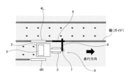
- FIG. 4 is a diagram showing an example of a seeding machine according to a second embodiment of the present invention.
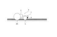
- FIG. 5 is a side view of the seeding machine shown in FIG. 4.
- the seeding machine 9 shown in FIGS. 4 and 5 is a manual three-wheel type seeding machine, and a front wheel 3 is provided on the front side of the base 2 in the traveling direction of the sowing machine 9.
- Left and right rear wheels 4R and 4L are provided on the rear side of the vehicle.
- a base body 2 is supported by these wheels 3, 4R, and 4L, and a seeder 5 is provided on the base body 2. Since the other configurations are the same as those shown in FIG. 1, the same reference numerals as in FIG. 1 are given and the explanation thereof will be omitted.
- the operation of the second embodiment will be explained together with the operation of the third embodiment.
- FIG. 6 is a diagram showing an example of a seeding machine according to a third embodiment of the present invention.
- FIG. 7 is a side view of the seeding machine shown in FIG. 6.
- the seeding machine 10 shown in FIGS. 6 and 7 is a manual two-wheeled type seeding machine, and wheels 11R and 11L are provided on the left and right sides of the base body 2, respectively, in the direction of movement of the seeding machine 10.
- a base body 2 is supported by the wheels 11R and 11L, and a seeder 5 is provided on the base body 2. Since the other configurations are the same as those shown in FIG. 1, the same reference numerals as in FIG. 1 are given and the explanation thereof will be omitted.
- the seeding machines 9 and 10 are first run along a groove such as a ridge or a ditch. Run to form ruts. After traveling a predetermined distance, the directions of the sowing machines 9 and 10 are reversed by operating the steering device as in the first embodiment, and the traveling positions are shifted by the width of the sowing machines 9 and 10. Then, the position detection device 6 is pressed into engagement with the ruts formed by the travel before turning back, and the vehicle is driven through the field in this state.
- the method of reversing the seeding machines 9 and 10 is shown by turning the seeding machines 9 and 10, but it may also be a method of switching back and moving backward.
- the position detection device 6 When the seeding machines 9 and 10 are running along the ruts, that is, along the guides, the position detection device 6 extends along the direction of movement of the guides and the seeding machines 9 and 10.
- the position detection device 6 is not bent or deformed in the left-right direction.
- the amount of deformation of the position detection device 6 in the left-right direction is smaller than that in the case where the seeding machine 1 moves in the left-right direction.
- the position detection device 6 is deflected and deformed according to the above-mentioned principle.
- the amount of deformation of the position detection device 6 changes depending on the amount of movement of the seeding machines 9 and 10 in the left-right direction
- the amount of deformation of the sowing machine 9 at the current time relative to the guide in the left-right direction is determined.
- 10 travel positions can be easily grasped. Thereby, the running positions of the seeding machines 9, 10 can be corrected and the seeding machines 9, 10 can be made to travel along the guide. In this way, even in the second embodiment and the third embodiment, the same operations and effects as in the first embodiment can be obtained.
- FIG. 8 is a diagram showing an example of a seeding machine according to a fourth embodiment of the present invention.
- FIG. 9 is a side view of the seeding machine shown in FIG. 8.
- the rigidity of the position detection device 6 is increased compared to the rigidity of the position detection device 6 of the first to third embodiments, and the position detection is performed as the seeding machine 12 moves in the left and right direction.
- the device 6 is configured to be swingable in the left-right direction.
- the position detection device 6 shown in FIGS. 8 and 9 is made of the same metal material as the arm parts 7 and 8.
- the position detecting device 6 of the fourth embodiment is less likely to be bent and deformed. Further, one end of the position detection device 6 is connected to the tip of the second arm portion 8 so as to be swingable in the left-right direction. The position detection device 6 only needs to be connected to the second arm portion 8 so as to be able to swing in the left-right direction. One end of the detection device 6 is connected.
- the two-wheel type seeding machine 12 is shown in FIGS. 8 and 9, a three-wheeled type seeding machine or a four-wheeled type seeding machine may be used instead. Since the other configurations are the same as those shown in FIG. 1, the same reference numerals as in FIG. 1 are given and the explanation thereof will be omitted.
- the seeding machine 12 is run along grooves such as ridges or ditches to form ruts. After traveling a predetermined distance, the direction of the seeding machine 1 is reversed by operating the steering device in the same manner as in the first to third embodiments, and the traveling position is shifted by the width of the seeding machine 1. . Then, the tip of the position detection device 6 is pressed and engaged with the ruts formed by the run before turning back, and in this state, the track is run through the field.
- the rigidity of the position detection device 6 of the fourth embodiment is greater than the rigidity of the position detection device 6 of the first to third embodiments. Therefore, even if the tip of the position detecting device 6 is pressed against the ruts, the position detecting device 6 is hardly bent or deformed.
- the position detection device 6 When the seeding machine 1 is traveling along a rut, that is, a guide, the position detection device 6 extends along the traveling direction of the seeding machine 12, and the position detection device 6 swings in the left and right directions with respect to the traveling direction. There's nothing to do.
- the angular range of the swinging of the position detection device 6 in the left-right direction is smaller than that in the case where the seeding machine 1 moves in the left-right direction, as will be described later. Therefore, the angle ⁇ formed by the position detection device 6 and the second arm portion 8 is maintained substantially constant on a plane parallel to the field and to each other. In the fourth embodiment, it is maintained at approximately 90 degrees. In this way, the angle ⁇ formed by the position detection device 6 and the second arm portion 8 on the plane when the seeding machine 12 is traveling along the guide is defined as the reference angle ⁇ 0 .
- the angle ⁇ formed by the position detection device 6 and the second arm portion 8 changes from the reference angle ⁇ 0 described above. Specifically, as shown in FIG. 8, when the seeding machine 12 moves away from the rut, the angle ⁇ becomes larger than the reference angle ⁇ 0 . On the other hand, when the seeding machine 12 moves in the left-right direction so as to approach the rut, the angle ⁇ becomes smaller than the reference angle ⁇ 0 .
- the amount of change in the angle ⁇ from the reference angle ⁇ 0 changes depending on the amount of movement of the seeding machine 12 in the left-right direction. Therefore, based on the angle ⁇ formed by the position detection device 6 and the second arm portion 8, it is possible to easily grasp the current traveling position of the seeding machine 12 with respect to the guide in the left-right direction. As a result, similar to the first to third embodiments, the seeding machine 12 can be run along the guide. In this way, even in the fourth embodiment, the same operations and effects as in the first to third embodiments can be obtained.
- FIG. 10 is a diagram showing an example of a seeding machine according to a fifth embodiment of the present invention.
- FIG. 11 is a side view of the seeding machine shown in FIG. 10.
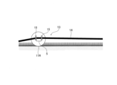
- the example shown in FIGS. 10 and 11 is an example in which a flexible linear body 14 stretched in advance on a flooded field is used as a guide, and the seeding machine 13 is configured to run along the linear body 14. It is.
- the seeding machine 13 shown in FIGS. 10 and 11 is a manual two-wheel type seeding machine, and the central part in the width direction of the front end and rear end of the base 2 of the seeding machine 1 is A position detection device 15 is provided at each of the positions.
- the position detection device 15 shown here is configured in a plate shape, for example.
- a slit that is approximately the same as the outer diameter of the linear body 14 or slightly wider than the outer diameter of the linear body 14 is formed in the plate.
- the linear body 14 is configured to be relatively movably engaged with the slit. In FIG. 11, the linear body 14 is lifted up by the position detection device 15, but the linear body 14 is positioned slightly above the position detection device 15 and stretched in a straight line so that it touches the position detection device 15. It doesn't matter if it doesn't exist.
- the position detection device 15 may be fixed to the base 2, or may be configured to be movable in the width direction (horizontal direction) of the base 2. 10 and 11 show a case where the position detection device 15 is fixed to the base 2. In FIG. When the position detection device 15 is fixed to the base body 2, the relative position of the seeding machine 13 with respect to the guide can be determined by the bending angle of the linear body 14. In addition, when the position detection device 15 is configured to be movable in the width direction (horizontal direction) of the base body 2, the seeding machine relative to the guide can be detected by reading the amount of displacement in the left and right direction from a preset reference position or initial position. 13 relative positions can be grasped.
- the seeding machine 13 is an example of the fifth embodiment, and is a drum seeder 5 with a position detection device 15 attached thereto. Note that the handle for operating the drum seeder is omitted for simplicity.
- the linear body 14 is preferably one that becomes linear by applying tension, and as long as it is such a linear body 14, there are no restrictions on the material that constitutes the linear body 14. Examples of the material constituting the linear body 14 include rope, rope, string, thread, thread, fishing line, resin wire, wire rope, steel wire, and metal wire. Since the linear body 14 only needs to be linearized by tension, it may be located above water or may be located underwater.
- a plurality of linear bodies 14 may be installed in the field at predetermined sowing intervals. Alternatively, a single linear body 14 is stretched in a straight line in a field, and the seeding machine 13 is run along the linear body 14 to sow seeds. After that, one linear body 14 is stretched in a straight line in the field at a predetermined sowing interval, and the seeding machine 13 is run along the linear body 14 to sow the seeds. You may repeat this.
- the number of linear bodies 14 stretched on the field is not limited.
- At least one linear body 14 is stretched in a straight line along a planned travel line along which a seeding machine 13 is to travel in a field in a flooded state after puddling.
- the linear body 14 is passed through the slit of the position detection device 15 of the sowing machine 13, and in this state, the sowing machine 13 is run along the linear body 14 to sow seeds.
- the direction of the sowing machine 13 is reversed or switched back in the same manner as in the first to fourth embodiments, and the traveling position is shifted by the width of the sowing machine 13. Then, the linear body 14 is stretched in a straight line again on the field.
- the linear body 14 is passed through the slit of the position detection device 15 of the sowing machine 13, and in this state, the sowing machine 13 is run along the linear body 14 to sow seeds. Repeat this.
- the above-mentioned planned travel line means the course on which the seeding machine 13 is scheduled to travel.
- both the linear body 14 on the front side and the linear body 14 on the rear side maintain a straight shape in the direction of movement of the seeding machine 13. Therefore, the linear body 14 is not deformed in the left-right direction.
- the bending angle of the linear body 14 becomes smaller compared to the case where the seeding machine 1 moves in the left-right direction, as described later.
- the position detection device 15 is fixed to the base body 2 as shown in FIGS. 10 and 11.
- the portion of the linear body 14 passed through the slit of the position detection device 15 moves to one side in the left-right direction together with the seeding machine 13. Therefore, the linear body 14 is bent using the slit of the position detection device 15 as an inflection point.
- the bending angle of the linear body 14 on a plane parallel to the field changes according to the amount of movement of the seeding machine 13 in the left-right direction, and gradually becomes smaller as the amount of movement of the seeding machine 13 in the left-right direction increases. . In other words, the bending of the linear body 14 increases.
- the bending angle of the linear body 14 is visually confirmed.
- the linear body 14 is positioned slightly above the position detection device 15 and stretched in a straight line so that it does not touch the position detection device 15, the linear body 14 can be used as a landmark to guide the user in the left and right direction. The deviation of the position detection device 15 from the linear body 14 is visually confirmed.
- the position detection device 15 is configured to be movable in the width direction (horizontal direction) of the base body 2.
- the position detection device 15 moves with respect to the reference position. Based on the amount of displacement of the position detection device 15 with respect to this reference position, it is possible to grasp the relative position of the seeding machine 13 with respect to the linear body 14, which is the planned travel line. Then, by changing the course of the seeding machine 13 so as to return the position detection device 15 to the reference position, the seeding machine 13 can be returned to the planned travel line.
- the traveling schedule in the left-right direction is determined.
- the current running position of the seeding machine 13 with respect to the line can be easily grasped.
- the seeding machine 13 can be run similarly to the first to fourth embodiments. In this way, even in the fifth embodiment, the same operations and effects as in the first to fourth embodiments can be obtained.
- the interval at which the linear bodies 14 are stretched may be adjusted as appropriate, or a relay portion may be provided to suppress the bending of the linear bodies 14. .
- the tension that causes the linear body 14 to be stretched linearly can be reduced, and the bending of the linear body 14 can be suppressed.
- FIG. 12 is a diagram showing an example of a seeding machine according to a sixth embodiment of the present invention.
- FIG. 13 is a side view of the seeding machine shown in FIG. 12.
- the seeding machine 16 shown in FIGS. 12 and 13 is a manual two-wheel type seeding machine like the seeding machine 10 of the third embodiment.
- the seeding machine 16 has a handle 17 relative to the base body 2 and the seeder 5 such that the handle 17 as a steering device is positioned on the front side in the front-back direction of the seeding machine 16 or on the rear side in the front-back direction. can be installed.
- the 12 and 13 has a rectangular ring shape, and among the four sides of the handle 17, the first side 17a is in a direction substantially parallel to the width direction of the seeding machine 16. It extends to The first side 17a of the handle 17 is rotatably attached to the base body 2, the seeder 5, and the wheel 11 about a rotating shaft (not shown).
- the handle 17 may be rotatably attached to the base body 2 via a hinge (not shown).
- a sleeve (not shown) configured to arrange the rotating shaft of the wheel 11 inside with a predetermined gap may be attached to the rotating shaft, and the handle 17 may be attached to the rotating shaft via the sleeve.
- the handle 17 is attached to the rotating shaft of the wheel 11 via a sleeve.
- the operator uses the second side 17b of the handle 17, which is substantially parallel to the first side 17a, to push or pull the seeding machine 16 to move it.
- the seeding machine 16 is moved by pulling it using a handle 17.
- the description of the seeder 5 is omitted in FIG. 12, but the seeder 5 is a cylindrical piece with a hole that also serves as a base 2, and is used to store and sow seeds. It is composed of
- One end of the second arm portion 8 in the length direction is fixed to the left end of the second side 17b of the handle 17 in the direction of movement of the seeding machine 16.
- the second arm portion 8 extends in a direction substantially parallel to the width direction of the seeding machine 16.
- the means for fixing the second arm portion 8 to the handle 17 may be conventionally known fixing means, such as adhesive, welding, riveting, bolting, etc. Since the other configurations are the same as those shown in FIG. 8, the same reference numerals as in FIG. 8 are given and the explanation thereof will be omitted.
- the seeding machine 16 is run along grooves such as ridges or ditches to form ruts. After traveling a predetermined distance, the seeding machine 16 is temporarily stopped and, as shown in FIG. 13, the handle 17 is rotated rearward in the traveling direction about the rotation axis of the wheel. Further, the running position is shifted by the width of the seed sowing machine 16, and the position detection device 6 is pressed into engagement with the rut formed by the running before (hereinafter referred to as "immediately") the handle 17 is rotated. Then, the sowing machine 16 is caused to run in the opposite direction to the direction in which the sowing machine 16 moves immediately before the handle 17 is rotated. That is, in the example shown in FIG. 12, the seeding machine 16 is switched back.
- the distance between the position detection device 6 and the guide is approximately constant, and the position detection device 6 is traveling along the guide or the seeding machine. 16 in the direction of travel. In other words, the position detection device 6 is not bent and deformed in the left and right directions with respect to the traveling direction. Alternatively, the amount of deformation of the position detection device 6 in the left-right direction is smaller than that in the case where the seeding machine 1 moves in the left-right direction.
- the position detection device 6 is deflected and deformed according to the above-mentioned principle.
- the amount of deformation of the position detection device 6 changes depending on the amount of movement of the seeding machine 16 in the left-right direction. Therefore, based on the amount of deformation of the position detection device 6, the current running position of the seeding machine 16 relative to the guide in the left-right direction can be easily grasped. Thereby, the traveling position of the seeding machine 16 can be corrected and the seeding machine 16 can be made to travel along the guide. In this way, even in the sixth embodiment, the same operations and effects as those of the above-described embodiments can be obtained.
- the running direction when the seeding machine first runs through the field (hereinafter referred to as the reference direction) and the running direction when the seeding machine runs through the field after that are approximately parallel to each other, that is,
- the azimuth angle which is the angle formed by these traveling directions, is less than or equal to a predetermined angle.
- the azimuth angle is preferably 6° or less, more preferably 3° or less. For example, if the azimuth is 6° and the seeding machine travels 10 m from the predetermined position, the distance between the line along the reference direction and the seeding machine, that is, the width of the gap, is about 1.0 m.
- the deviation width will be about 0.5 m.
- the azimuth angle be as small as possible in order to make the deviation width as small as possible. Therefore, it is preferable for the azimuth angle to be as small as possible for regular seeding throughout the field.
- the deviation width means the distance between the intersection of a line along the reference direction and a line that is perpendicular to the line along the reference direction and passes through a point where the seeding machine has traveled 10 m from the predetermined position, and the said point. are doing.
- FIG. 14 is a diagram for explaining a state in which seeds are regularly sown throughout the field, and shows the direction in which the seeding machine traveled when it traveled back and forth across the field multiple times.
- the directions in which the seeding machine traveled are substantially parallel to each other when it travels back and forth across the field multiple times.
- the azimuth angle formed by the direction in which the seeding machine travels on the first outbound trip, that is, the reference direction D1, and the direction D2 in which the seeding machine travels in the fifth outbound trip is approximately 0°.
- FIG. 15 is a diagram for explaining a state in which seeds are not sown regularly throughout the field, and shows the direction in which the seeding machine traveled when it traveled back and forth across the field multiple times.
- the directions in which the seeding machine traveled when it traveled back and forth across the field multiple times are not substantially parallel to each other.
- the azimuth angle formed by the direction in which the seeding machine travels on the first outbound trip, that is, the reference direction D1, and the direction D2 in which the seeding machine travels in the fifth outbound trip is not approximately 0°.
- the seeding machine according to the seventh embodiment of the present invention acquires a signal from a positioning satellite of a satellite positioning system, and based on the acquired signal, the position of the seeding machine (hereinafter referred to as position information) and direction. Configured to calculate angles.
- the running position that is, the running direction of the seeding machine can be corrected based on the above-mentioned position information and azimuth.
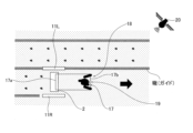
- FIG. 16 is a diagram showing an example of a seeding machine according to a seventh embodiment of the present invention.
- FIG. 17 is a side view of the seeding machine shown in FIG. 16.
- 16 and 17 is a manual two-wheel type seeding machine configured almost similarly to the seeding machine 16 of the sixth embodiment, and the seeding machine 18 shown in FIG.
- a holder (not shown) is installed.
- a mobile terminal 19 configured to be able to acquire signals from a satellite positioning system is removably attached to the holder. Note that the mobile terminal 19 described above corresponds to the position information acquisition device in the present invention.
- the satellite positioning system may be GPS (Global Positioning System) or GNSS (Global Navigation Satellite System).
- GNSS Global Navigation Satellite System
- the satellite positioning system may be RTK (Real Time Kinematic, hereinafter referred to as GNSS-RTK) or DGPS (Differential Global Positioning System, hereinafter referred to as GNSS-DGPS) among GNSS.
- RTK Real Time Kinematic
- DGPS Different Global Positioning System
- the accuracy of the mobile station's position information is improved by correcting the position information based on the signal from the positioning satellite received by the mobile station using the position information based on the signal from the positioning satellite received by the fixed station.
- the mobile terminal 19 attached to the handle 17 functions as a mobile station.
- the description of the position detection device 6 is omitted. Since the other configurations are the same as those shown in FIG. 13, the same components as those shown in FIG. 13 are given the same reference numerals as those in FIG. 13, and the description thereof will be omitted.
- FIG. 18 is a diagram showing an example of the configuration of the mobile terminal 19.
- the mobile terminal 19 shown in FIG. 18 includes a receiving section 21, a control section 22, a storage section 23, a display section 24, and an operation section 25.
- the receiving unit 21 is configured to receive signals from a plurality of positioning satellites 20, and may be a conventionally known antenna, for example. In order to obtain highly accurate position information, it is preferable that the receiving unit 21 receives signals from a plurality of positioning satellites 20. Specifically, it is preferable that the receiving unit 21 receives signals from four or more positioning satellites 20. By calculating the current position based on the position information based on the signals from the three positioning satellites 20 and the time received from the fourth positioning satellite 20, the calculated current position and the actual position can be calculated. This is because the difference in position can be reduced.
- the signal received by the receiving section 21 is input to the control section 22.
- the control unit 22 is mainly composed of a microcomputer, and is configured to perform calculations based on input data, pre-stored data, and calculation formulas, and output the results.
- the control unit 22 shown in FIG. 18 performs calculations based on the signal received by the reception unit 21, and calculates the position information, travel trajectory, reference direction, and azimuth of the seeding machine 18 in the field.
- the storage unit 23 is, for example, a part that stores various information calculated by the control unit 22, and map information may be stored in advance in the storage unit 23.
- the map information may be stored in a server or the like connected to the Internet and may be configured to be acquired via wireless communication.
- the display unit 24 is a part that displays various information and map information calculated by the control unit 22, and by displaying the various information and map information described above on the display unit 24, the operator can visually confirm the information. It looks like this. Note that it is preferable to display the position information, travel trajectory, reference direction, and azimuth of the seeding machine 18 in a superimposed manner on the map information.
- the display unit 24 may be a conventionally known monitor.
- the operation unit 25 is configured to be operated by an operator to read out various information stored in the storage unit 23 and display it on the display unit 24, for example.
- an operator causes the seeding machine 18 to travel along a guide that is currently used as a guide.
- the mobile terminal 19 receives signals from a plurality of positioning satellites 20, and calculates the current position information, travel trajectory, reference direction, and azimuth of the seeding machine 18 in the field based on the received signals.
- the information is stored in the storage section 23 of the mobile terminal 19 and displayed on the display section 24. Further, each piece of information is updated each time signals from a plurality of positioning satellites 20 are received. That is, the information stored in the storage section 23 is updated, and the updated information is displayed on the display section 24.
- the operator can always check with the latest information whether or not the sowing machine 18 is traveling along the reference direction. can do. Even if the misalignment of the seeding machine 18 in the left and right directions with respect to the guide is a small misalignment that does not pose a problem, if such misalignment accumulates and the azimuth becomes larger than a predetermined angle, the steering wheel 17 must be steered.
- the direction in which the seeding machine 18 travels can be corrected by As a result, the azimuth angle can be made as small as possible, and even if the vehicle travels back and forth multiple times, the multiple rows formed by the seeds sown in the field can be made substantially parallel to each other.
- the seeding machine 18 of the seventh embodiment compared to the seeding machines 1, 9, 10, 12, 13, and 16 of each embodiment described above, the seeding machine 18 traveled back and forth in the field multiple times.
- seeds can be sown regularly throughout the field.
- the seeding machine 18 of the seventh embodiment includes a position detection device 6. Therefore, even if it is difficult to receive a signal from the positioning satellite 20 due to bad weather, radio interference, or a failure of the mobile terminal 19, the position detection device 6 can be moved along the guide based on the amount of deformation of the position detection device 6. The seeding machine 18 can be run to sow seeds at predetermined positions. In other words, substantially the same actions and effects as in the sixth embodiment can be obtained.
- the present invention is not limited to the first to seventh embodiments described above.
- the seeding machines 1, 9, 10, 13, 16, 18 at the present time relative to the planned travel line are visually checked.
- the system is designed to detect deviations in the running position of the vehicle.
- the deformation amount of the position detection device 6 or the linear body 14 may be detected using a strain sensor, a laser distance meter, or the like. If the amount of change in the position detection device 6 or linear body 14 detected by a strain sensor, laser distance meter, etc. exceeds a preset threshold, a warning will be sent to the operators of the seeding machines 1, 9, 10, 13, 16, and 18. It may also be configured to issue a warning.
- the steering device may be configured to be controlled based on the amount of change in the position detection device 6 described above, and the running positions of the seeding machines 1, 9, 10, 13, 16, and 18 may be automatically corrected. You can.
- the angle ⁇ formed between the position detection device 6 and the second arm portion 8 may be detected using a laser distance meter, an angle sensor, or the like. If the angle ⁇ detected by a laser distance meter, an angle sensor, etc. exceeds a preset threshold, a warning is issued to the operator of the seeding machine 12 to prompt the operator to correct the running position of the seeding machine 12. You may do so.
- the steering device may be configured to be controlled based on the angle ⁇ mentioned above, and the traveling position of the seeding machine 12 may be automatically corrected.
- the detection of the running position by the above-mentioned position detection devices 6 and 15 and the detection of the running position by a strain sensor, a laser distance meter, an angle sensor, etc. may be used together.
- the position detection devices 6 and 15 according to this embodiment can The running position of the vehicle can be detected and understood.
- the intensity of the ruts is low, and it is difficult to trace the ruts with the position detection device 6 of the first to fourth embodiments, the sixth embodiment, and the seventh embodiment, or to engage the position detection device 6 with the ruts.
- a laser distance meter can detect the driving position.
- the detection accuracy of the running position of the device as a whole can be improved, and the seeding machines 1, 9, 10, 12, 13, 16, 18 can be moved along the rut. It becomes easier to run.
- the traveling position may be detected while checking underwater ruts using underwater box glasses, polarized glasses, or the like. In cases where the strength of the ruts is low or the tension of the linear body 14 is low and it becomes difficult to detect the running position using the position detection devices 6 and 15, and when the water transparency in the field is high, The running position can be detected using underwater bin glasses, polarized glasses, etc. Therefore, compared to the case where the position detection devices 6 and 15 are used alone, the detection accuracy of the traveling position of the device as a whole can be improved, and the seeding machines 1, 9, 10, 12, 13, 16, 18 becomes easier to drive.
- the driving force source can be controlled by the seeding machines 1, 9, 10, 12, 13, 16,
- the driving force may be small enough to assist the operation of step 18. Even when the driving force generated by the driving force source is small, the labor load can be reduced. Furthermore, since a driving force source with a small driving force can be used, costs related to the driving force source can be reduced.
- the seeding machine 13 in order to engage the linear body 14 functioning as a guide with the position detection device 15 provided on the seeding machine 13, the seeding machine 13 can also be moved by a small boat, a hovercraft, a drone, etc. that does not come into direct contact with the soil surface. can be configured. Even in the seeding machine 13 having such a configuration, by providing the position detection device 15 according to the embodiment of the present invention, the amount of deformation of the linear body 14 or the amount of displacement of the position detection device 15 with respect to the base body 2 can be adjusted. Based on this, the traveling position of the seeding machine 13 can be grasped. Therefore, the same functions and effects as those of the first to sixth embodiments can be obtained.
- Inventive example 1 is an example in which a four-wheel type seeding machine is used and a position detection device configured in substantially the same manner as the position detection device 6 of the first embodiment is attached thereto. Further, in order to make the position detecting device flexible, this is an example in which the position detecting device is configured in the shape of a rod made of ultra-high molecular weight polyethylene (in Table 1 described later, it is described as a flexible rod). Iron-coated seeds with a specific gravity of 1.5 g/cm 3 were used as rice seeds to be sown. A seeding machine having the above-mentioned configuration was run through a flooded field to sow iron-coated seeds.
- Inventive example 2 is an example in which a two-wheel type seeding machine is used and a position detection device configured in substantially the same manner as the position detection device 15 of the fifth embodiment is attached thereto. This is also an example of seeding by running a seeding machine along a rope that has been installed in advance in a field. The same rice seeds as in Invention Example 1 were used.
- Invention example 3 is an example in which a three-wheel type seeding machine is used and a position detection device configured in substantially the same manner as the position detection device 6 of the first embodiment is attached to this. Furthermore, this is an example in which the position detection device is made of a piano wire, that is, a high-tensile steel wire.
- the seeding machine with the above-mentioned configuration was operated in a partially flooded field with shallow water management to sow iron-coated seeds. The same rice seeds as in Invention Example 1 were used.
- Invention example 4 is an example in which a two-wheel type seeding machine is used and a position detection device configured in substantially the same manner as the position detection device 6 of the first embodiment is attached thereto. This is also an example in which the position detection device is made of split bamboo.
- the rice seeds used were iron oxide coated seeds with a specific gravity of 1.3 g/cm 3 .
- a seeding machine having the above-mentioned configuration was run through a flooded field to sow iron oxide coated seeds.
- Inventive Example 5 is an example in which reeds are used as the position detection device 6, and slag-coated rice seeds, which are coated with slag and have a specific gravity of 1.2 g/cm 3 , are used as the rice seeds. Other than that, the slag-coated seeds were sown in a flooded field in the same manner as in Invention Example 4.
- Inventive example 6 is an example in which a two-wheel type seeding machine is used, and a position detection device configured in substantially the same manner as the position detection device 6 of the fourth embodiment is attached to this so as to be able to swing in the left-right direction.
- the position detection device is made of the same metal material as the arm parts 7 and 8, for example.
- Iron-coated seeds similar to those in the first embodiment were used as rice seeds, and the iron-coated seeds were sown in rows by driving a seeding machine having the above-described configuration through a flooded field.
- Invention example 7 is an example in which a two-wheel type seeding machine is used and a position detection device configured in substantially the same manner as the position detection device 6 of the first embodiment is attached thereto. Further, the position detection device was constructed from polyoxymethylene resin. Iron-coated seeds having a specific gravity of 2.0 g/cm 3 were used as rice seeds, and the iron-coated seeds were sown in rows using the seeding machine configured as described above.
- Inventive Example 8 is an example in which the position detection device is made of polyamide resin, iron-coated seeds having a specific gravity of 3.0 g/cm 3 are used as rice seeds, and the iron-coated seeds are sown. Other than that, it was the same as Invention Example 7.
- the position detection device is made of polyester resin, iron-coated rice seeds with a specific gravity of 4.0 g/cm 3 are used, and the iron-coated seeds are grown by a seeding machine configured in the same manner as Inventive Example 1. This is an example of spot sowing. Other than that, it was the same as Invention Example 7.
- Inventive Example 10 is an example in which the position detection device was made of polyethylene resin and iron-coated seeds were scattered in the field. Other than that, it was the same as Invention Example 1.
- Invention Example 11 is an example in which a fishing line was used as a guide instead of the rope in Invention Example 2, and iron-coated seeds were sown in a field. Other than that, it was the same as Invention Example 2.
- Invention example 12 is an example in which a stainless steel wire was used as a guide instead of the fishing line in invention example 11. Other than that, it was the same as Invention Example 11.
- Invention example 13 is an example in which a position detection device configured almost the same as the position detection device 15 of the fifth embodiment is attached to a small boat. This is also an example in which iron-coated seeds were scattered in a field using a wire rope that had been set up in advance in the field as a guide.
- Invention example 14 is an example in which a two-wheel type seeding machine is used, and a handle configured in substantially the same manner as the handle 17 described in the above-mentioned sixth embodiment is attached to the drum seeder of the seeding machine. Further, this is an example in which a position detection device configured in substantially the same manner as the position detection device 6 of the first embodiment is attached to the handle. That is, this is an example in which the seeding machine is configured to switch back. The operator can pull the handle backwards or check the status of the position detection device while pushing the handle. This is an example of a simplified device configuration. In addition, a position detection device was constructed of ultra-high molecular weight polyethylene, and the iron-coated seeds were sown in rows in the field as the seeding machine ran.
- Invention Example 15 uses a two-wheel type seeding machine, and includes a position detecting device configured almost the same as the position detecting device 6 of the first embodiment, and a mobile terminal using GNSS-RTK as a satellite positioning system. This is an example of how it is installed. In addition, correction information for correcting the position information based on the signal received by the mobile terminal was obtained from the Internet line connected by wireless communication. Furthermore, in order to make the position detecting device flexible, this is an example in which the position detecting device is configured in the shape of a rod made of a synthetic resin material (described as a flexible rod in Table 1 to be described later). Iron-coated seeds with a specific gravity of 1.5 g/cm 3 were used as rice seeds to be sown. A seeding machine having the above-mentioned configuration was run through a flooded field to sow iron-coated seeds in rows.
- Invention Example 16 is an example in which a mobile terminal using GNSS-RTK as a satellite positioning system is attached to the seeding machine of invention example 2.
- correction information for correcting the position information based on the signal received by the mobile terminal was obtained from the Internet line connected by wireless communication. Other than that, it was the same as Invention Example 2.
- Invention example 17 is an example in which a mobile terminal using GNSS-RTK as a satellite positioning system is attached to the seeding machine of invention example 6.
- correction information for correcting the position information based on the signal received by the mobile terminal was obtained from the Internet line connected by wireless communication. Other than that, it was the same as Invention Example 6.
- Comparative Example 1 is an example in which a conventionally known rotating marker was attached to a four-wheel type seeding machine, and the seeding machine was run to perform seeding using the streaks formed in the field by the rotating marker as a guide.
- the rice seeds uncoated rice seeds that were not coated with the above-mentioned seed coating agent were used.
- a seeding machine having the above-mentioned configuration was run on a field in a flooded field to sow rice seeds.
- Comparative Example 2 uses a two-wheel type seeding machine, and a rod having approximately the same rigidity as each arm part 7, 8 is attached to the tip of the second arm part 8 of the seeding machine so as not to swing in the left-right direction. This is an example of installing and tracing a track using the rod. Uncoated rice seeds were used as the rice seeds, and the rice seeds were sown by running a seeding machine having the above-mentioned configuration on a field in a flooded field.
- Comparative Example 3 is an example in which a seeding machine configured similarly to Comparative Example 1 was run in a flooded field to sow rice seeds. Other than that, it was the same as Comparative Example 1.
- Comparative Example 4 is an example in which iron-coated rice seeds having a specific gravity of 1.5 g/cm 3 were used. Other than that, it was the same as Comparative Example 1.
- Comparative example 5 iron-coated rice seeds with a specific gravity of 1.5 g/cm 3 were used, and a seeding machine configured similarly to Comparative Example 2 was run in a flooded field to sow rice seeds. This is an example of spot sowing. Other than that, it was the same as Comparative Example 2.
- Comparative Example 6 is an example in which a two-wheel type seeding machine is used and a mobile terminal using GNSS-RTK as a satellite positioning system is attached to this. That is, Comparative Example 6 is an example in which the seeding machine is not equipped with the position detection device described above.
- correction information for correcting the position information based on the signal received by the mobile terminal was obtained from the Internet line connected by wireless communication. Iron-coated seeds with a specific gravity of 1.5 g/cm 3 were used as rice seeds to be sown. A seeding machine having the above-mentioned configuration was run through a flooded field to sow iron-coated seeds in rows.
- Coating the seeds with iron powder was performed according to the method described in the above-mentioned "Iron Coating Direct Sowing Manual 2010". Materials other than iron powder, specifically iron oxide and slag, were coated on the surface of rice seeds using a binder.
- the azimuth angle means the angle between the reference direction and the direction in which the seeding machine is currently traveling. Specifically, the seeding machine was run straight for 10 m from a predetermined position, and then turned back and run straight for 10 m. Such a round trip was performed five times. The direction in which the seeding machine travels on the first outbound trip was defined as the reference direction, and the angle between this and the direction in which the seeding machine traveled in the fifth outbound trip was defined as the azimuth angle.
- the azimuth angle was determined as follows. The symbol “ ⁇ ” indicates that the azimuth angle is 1° or less. The symbol “ ⁇ ” indicates that the azimuth angle is greater than 1° and less than 3°. The symbol “ ⁇ ” indicates that the azimuth angle is greater than 3 degrees and less than 6 degrees. The "x” symbol indicates that the azimuth angle exceeds 6°.
- Wash-off resistance refers to the difficulty in moving seeds sown in a flooded field. After a predetermined period of time had elapsed after the seeds were sown in the field using a seeding machine, evaluation was made based on the distance traveled by the seeds from the sowing position. In the case of falling water sowing, this is the distance traveled after sowing and returning to flooding. The judgment was as follows.
- the symbol “ ⁇ ” shown in Table 1 indicates that the above-mentioned moving distance is 3 cm or less.
- the symbol “ ⁇ ” indicates that the moving distance is more than 3 cm and less than 10 cm.
- the symbol “ ⁇ ” indicates that the moving distance is more than 10 cm and less than 20 cm.
- the "x” symbol indicates that the moving distance exceeds 20 cm.
- the seeding machine and the seeding method according to the present invention as shown in Table 1, in Invention Examples 1 to 17, compared to Comparative Examples 1 to 6, the seeding machine
- the seeds can be easily positioned, that is, they can be sown regularly at regular intervals throughout the field.
- iron-coated seeds, iron oxide-coated seeds, slag-coated seeds, etc. which have a higher specific gravity than uncoated seeds, are used, they are less likely to be washed away compared to uncoated seeds.
- the seeds can be sown in a flooded field, there is no need to drop the seeds into water during sowing, and as a result, the amount of water used can be reduced compared to the conventionally known direct sowing method.
- the field since the field is maintained in a state of being flooded with water, it is possible to suppress the growth and overgrowth of weeds as well as the damage caused by birds compared to a field in a state of flooding.
Landscapes
- Life Sciences & Earth Sciences (AREA)
- Soil Sciences (AREA)
- Environmental Sciences (AREA)
- Engineering & Computer Science (AREA)
- Mechanical Engineering (AREA)
- Sowing (AREA)
Abstract
Description
[1]湛水状態の圃場を走行可能に構成された車輪に支持された基体に、前記圃場に種子を播くシーダーが設けられている播種機であって、前記車輪によって前記圃場に形成された轍、前記圃場に予め形成されている水路、前記圃場に予め形成された線状の溝、および、前記圃場に直線状に予め張られた可撓性のある線状体のうち、少なくともいずれか一つをガイドとし、前記ガイドに係合する前記基体に設けられた位置検出装置を備えている、播種機。
[2]前記位置検出装置は、前記車輪によって前記圃場に形成された轍、前記圃場に予め形成されている水路、および、前記圃場に予め形成された線状の溝のうち、少なくともいずれか一つをガイドとし、前記ガイドに対して進行方向に対する左右方向に前記基体が移動することによって前記左右方向に変形し、もしくは、前記左右方向に揺動する、[1]に記載の播種機。
[3]前記位置検出装置はロッド状に構成されており、前記左右方向で前記位置検出装置と前記基体との間に予め定めた間隔をあけて前記位置検出装置を支持するように構成された支持機構が、前記基体に設けられている、[2]に記載の播種機。
[4]前記位置検出装置は、前記圃場に直線状に予め張られた可撓性のある線状体をガイドとし、前記線状体に対して相対移動可能に係合させられる、[1]に記載の播種機。
[5]前記位置検出装置は、前記線状体を相対移動可能に係合するように構成されたスリットと、前記線状体を相対移動可能に係合するように前記位置検出装置の板厚方向に貫通して形成された孔とのうち、いずれか一方を有している、[4]に記載の播種機。
[6]衛星測位システムから取得した信号に基づいて位置情報を取得する位置情報取得装置を更に備えている、[1]に記載の播種機
[7][1]ないし[5]のいずれかに記載の播種機を用いて種子を播種する播種方法。
[8]前記種子は、金属材料を含む種子被覆剤が表面に被覆されていて比重が1.2g/cm3以上4.0g/cm3以下である、[7]に記載の播種方法。
(播種機)
図1は、本発明の第1実施形態に係る播種機の一例を示す図である。図1に示す播種機1は手動式4輪タイプの播種機1であって、播種機1の進行方向で基体2の前方側に左右の前輪3R、3Lが設けられており、進行方向で基体2の後方側に左右の後輪4R、4Lが設けられている。それらの車輪3R、3L、4R、4Lによって基体2が支持されており、基体2にシーダー5が設けられている。なお、播種機1は走行のための駆動力を生じる駆動力源を有していてもよい。また、播種機1における後方に図示しない操舵装置が設けられており、オペレーターが操舵装置を操作することによって播種機1の進行方向を変更できるようになっていてよい。但し、操舵装置が無くても播種機の進行方向をコントロールできるのであれば、ステアリングホイールなどの特段の操舵装置は必須ではない。
播種機1の進行方向で基体2の前方側に、上述したガイドに係合するように構成された位置検出装置6が設けられている。位置検出装置6は、図1に示す例では、ロッド状に構成されており、支持機構を介して基体2に支持されている。その支持機構は基体2の前端部におけるほぼ中央部分から播種機1の前方に突出する第1アーム部7と、第1アーム部の先端部から左側に延びる第2アーム部8とを有している。進行方向での基体2の前端部からの第1アーム部7の突出長さは、第1アーム部7の一方の端部(以下、第1アーム部7の先端部と記す。)が前輪3R、3Lよりも前方に位置する長さに設定されている。第1アーム部7の長さ方向で他方の端部は、連結手段によって基体2に一体に連結されている。その連結手段は従来知られた連結手段であってよく、例えば、接着剤や溶接、リベット止め、ボルト止めなどであってよい。第1アーム部7の先端部に、第1アーム部7の軸線を回転中心軸線として回動可能に、第2アーム部8の長さ方向での一方の端部が連結されている。
ガイドは、一例として、湛水状態の圃場に形成された溝状の轍や水路(明渠)、従来知られたマーカーによって圃場に形成した筋などを挙げることができる。それらは湛水状態の圃場に代かきを行って土壌表面がある程度硬くなるのを待って形成することが好ましい。こうすることによって溝や轍、水路などの強度をある程度高くすることができ、位置検出装置6によってなぞりやすくなる。つまり、ガイドに係合した状態を保ちやすくなる。また、圃場に排水用の水路を設計通りに形成することができる。代かき前に圃場に水路や溝を形成し、その後に代かきを行った場合に、前記代かき前に形成した水路や溝が、代かき後においても水路や溝として機能するのであれば、代かき前に溝、水路を形成してもよい。ガイドの別の例として、畝やレールなどを利用することができる。また、ロープなどの圃場に直線状に予め張られた可撓性のある線状体を利用することができる。ガイドは一つの形態を使えば効果が得られるが、異なる形態のガイドを組み合わせること、例えば溝とロープを組み合わせることも同様に効果が期待でき、本発明の範囲内である。
本発明の実施形態で使用する種子としては、イネが好ましい。イネの品種は制限されないのであって、ジャポニカ米、インディカ米、ジャバニカ米のいずれであっても適用できる。イネは高温多湿地域の水田で栽培されることが多いため、本発明の効果が発揮できる。また、イネに替えて、湛水状態で播種する種子であれば、いずれの種子であっても好ましく適用される。
上述した鉄材料によって種子を被覆する方法は制限されない。例えば、「鉄コーティング湛水直播マニュアル2010(独立行政法人 農業・食品産業技術総合研究機構 近畿中国四国農業研究センター編)」に示されているように、手作業での被覆をはじめ、従来から公知の混合機を用いるなど、いずれの方法であってもよい。
第1実施形態に係る播種機1の作用について説明する。湛水状態の圃場に代かきを行って土壌表面を均す。そして、土が締まって土壌表面がある程度硬くなった後に、例えば、圃場の周囲に形成された畝または明渠などの溝に沿って播種機1を走行させる。つまり、畝または溝をガイドとして播種機1を走行させる。これにより、圃場に溝状の轍が形成される。また、播種機1の走行に伴って播種機1の進行方向に沿ってシーダー5によって鉄コーティング種子が播かれる。
図4は、本発明の第2実施形態に係る播種機の一例を示す図である。図5は、図4に示す播種機の側面図である。図4および図5に示す播種機9は、手動式3輪タイプの播種機であって、播種機9の進行方向で基体2の前方側に前輪3が設けられており、進行方向で基体2の後方側に左右の後輪4R、4Lが設けられている。それらの車輪3、4R、4Lによって基体2が支持されており、基体2にシーダー5が設けられている。他の構成は図1に示す構成と同様であるため、図1と同様の符号を付してその説明を省略する。第2実施形態の作用については、第3実施形態の作用と共に説明する。
図6は、本発明の第3実施形態に係る播種機の一例を示す図である。図7は図6に示す播種機の側面図である。図6および図7に示す播種機10は、手動式2輪タイプの播種機であって、播種機10の進行方向で基体2の左右両側のそれぞれに車輪11R、11Lが設けられている。その車輪11R、11Lによって基体2が支持されており、基体2にシーダー5が設けられている。他の構成は図1に示す構成と同様であるため、図1と同様の符号を付してその説明を省略する。
第2実施形態、および、第3実施形態に係る播種機9、10であっても、代かき後の湛水状態の圃場において、先ず、畝または明渠などの溝に沿って播種機9、10を走行させて轍を形成する。所定距離の走行後に、第1実施形態と同様に操舵装置を操作するなどして播種機9、10の向きを反転させ、また、播種機9、10の幅の分、走行位置をずらす。そして、折り返し前の走行によって形成された轍に位置検出装置6を押し付けて係合させ、その状態で、圃場を走行させる。図4や図6では播種機9、10の反転は、播種機9、10を回頭する方法を示したが、スイッチバックして後方に進む方法でもよい。
図8は、本発明の第4実施形態に係る播種機の一例を示す図である。図9は、図8に示す播種機の側面図である。ここに示す例は、位置検出装置6の剛性を第1実施形態ないし第3実施形態の位置検出装置6の剛性よりも増大させると共に、左右方向への播種機12の移動に伴って当該位置検出装置6を左右方向に揺動可能に構成した例である。具体的には、図8および図9に示す位置検出装置6は各アーム部7、8と同様の金属材料によって構成されている。そのため、第1実施形態ないし第3実施形態の位置検出装置6と比較して、第4実施形態の位置検出装置6は撓み変形しにくくなっている。また、第2アーム部8の先端部に対して、左右方向に揺動可能に位置検出装置6の一方の端部が連結されている。位置検出装置6は、左右方向に揺動可能に第2アーム部8に連結されていればよく、例えば、ユニバーサルジョイントやフックジョイント、ボールジョイントなどを介して第2アーム部8の先端部と位置検出装置6の一方の端部とが連結される。なお、図8および図9には、2輪タイプの播種機12を示してあるが、これに替えて3輪タイプの播種機や4輪タイプの播種機であってもよい。他の構成は図1に示す構成と同様であるため、図1と同様の符号を付してその説明を省略する。
代かき後の湛水状態の圃場において、先ず、畝または明渠などの溝に沿って播種機12を走行させて轍を形成する。所定距離の走行後に、第1実施形態ないし第3実施形態と同様にして操舵装置を操作するなどして播種機1の向きを反転させ、また、播種機1の幅の分、走行位置をずらす。そして、折り返し前の走行によって形成された轍に位置検出装置6の先端部を押し付けて係合させ、その状態で、圃場を走行させる。第4実施形態の位置検出装置6の剛性は、第1実施形態ないし第3実施形態の位置検出装置6の剛性よりも増大されている。そのため、轍に位置検出装置6の先端部を押し付けたとしても、位置検出装置6が撓み変形することはほとんどない。
図10は、本発明の第5実施形態に係る播種機の一例を示す図である。図11は、図10に示す播種機の側面図である。図10および図11に示す例は、湛水状態の圃場に予め張った可撓性のある線状体14をガイドとし、線状体14に沿って播種機13を走行させるように構成した例である。具体的には、図10および図11に示す播種機13は手動式2輪タイプの播種機であって、当該播種機1の基体2の前端部と後端部とにおける幅方向での中央部分に位置検出装置15がそれぞれ設けられている。ここに示す位置検出装置15は一例としてプレート状に構成されている。そのプレートに、線状体14の外径とほぼ同じ、あるいは、線状体14の外径よりもわずかに広いスリットが形成されている。そのスリットに線状体14を相対移動可能に係合させるように構成されている。図11では線状体14が位置検出装置15により持ち上げた形態になっているが、線状体14を位置検出装置15よりも少し上方に位置させて直線状に張り、位置検出装置15に触れない形態であっても構わない。
代かき後の湛水状態の圃場において、播種機13を走行させる走行予定線に沿って少なくとも一本の線状体14を直線状に張る。播種機13の位置検出装置15のスリットに線状体14を通し、その状態で線状体14に沿って播種機13を走行させて播種する。所定距離の走行後に、第1実施形態ないし第4実施形態と同様にして播種機13の向きを反転させ、あるいはスイッチバックさせ、また、播種機13の幅の分、走行位置をずらす。そして、圃場に再度、線状体14を直線状に張る。播種機13の位置検出装置15のスリットに線状体14を通し、その状態で線状体14に沿って播種機13を走行させて播種する。これを繰り返す。なお、上述した走行予定線とは、播種機13を走行させる予定の進路を意味している。
図12は、本発明の第6実施形態に係る播種機の一例を示す図である。図13は、図12に示す播種機の側面図である。図12および図13に示す播種機16は、第3実施形態の播種機10と同様に、手動式2輪タイプの播種機である。その播種機16は、操舵装置としてのハンドル17を播種機16の前後方向で前方側に位置させたり、前後方向で後方側に位置させたりするように、基体2やシーダー5に対してハンドル17が取り付けられる。具体的には、図12および図13に示すハンドル17は、矩形のリング状を成しており、そのハンドル17の四辺のうち、第1辺17aは播種機16の幅方向とほぼ平行な方向に延びている。当該ハンドル17の第1辺17aが基体2やシーダー5、車輪11の図示しない回転軸に対して回転可能な方式で取付けられる。例えば、図示しないヒンジを介して基体2にハンドル17が回動可能に取り付けられてもよい。あるいは、所定の隙間をあけて内側に車輪11の回転軸を配置するように構成された図示しないスリーブを回転軸に取り付け、そのスリーブを介して前記回転軸にハンドル17が取り付けられてもよい。図12および図13では、車輪11の回転軸にスリーブを介してハンドル17を取り付けた例を示している。上記の播種機16では、オペレーターは、ハンドル17の第1辺17aとほぼ平行な第2辺17bを使用して播種機16を押し動かしたり、引っ張って動かしたりするようになっている。なお、図12に示す例では、播種機16はハンドル17を使用して引いて動かすようになっている。また、図面を簡単にするため、図12では、シーダー5の記載を省略しているが、シーダー5は基体2を兼ね備えた穴の開いた円筒状のものであり、種子を格納し播種できるように構成されている。
代かき後の湛水状態の圃場において、先ず、畝または明渠などの溝に沿って播種機16を走行させて轍を形成する。所定距離の走行後に、播種機16を一旦停止させ、図13に示すように、ハンドル17を進行方向で後方側に車輪の回転軸を回転中心として回動させる。また、播種機16の幅の分、走行位置をずらすと共に、ハンドル17を回動させる前(以下、直前と記す)の走行によって形成された轍に位置検出装置6を押し付けて係合させる。そして、ハンドル17を回動させる直前の播種機16の進行方向とは反対方向に向かって播種機16を走行させる。つまり、図12に示す例では、播種機16をスイッチバックさせる。
ガイドに沿って播種機1、9、10、12、13、16を走行させる場合、ガイドに沿う方向と、実際に走行する方向に沿う方向との間には、僅かではあってもズレ(以下、エラーや方位角と記す場合がある。)が生じる場合がある。また、上述したガイドは常に一定ではなく、圃場で播種機1、9、10、12、13、16が往復する都度、異なる。そのため、圃場において播種機1、9、10、12、13、16が複数回往復走行すると、上述したエラーが次第に蓄積されてしまい、圃場全体に規則正しく播種できない可能性がある。ここで、圃場全体に規則正しく播種するとは、圃場に播かれた種子によって形成される複数の列が互いにほぼ平行であることを意味している。また、圃場を播種機が最初に走行したときの走行方向(以下、基準方向と記す。)と、その後に圃場を播種機が走行したときの走行方向とが互いにほぼ平行であること、つまり、それらの走行方向の成す角である方位角が予め決めた角度以下であることを意味している。一例として方位角は6°以下であることが好ましく、3°以下であることがより好ましい。例えば方位角が6°であって、播種機が所定位置から10m走行した場合には、基準方向に沿う線と播種機との間の距離つまりズレ幅は約1.0mとなる。方位角が3°であって、播種機が所定位置から10m走行した場合には、ズレ幅は約0.5mとなる。これらのことから、ズレ幅を可能な限り小さくするため、方位角は可能な限り小さいことが好ましい。したがって、方位角が可能な限り小さいことは、圃場全体に規則正しく播種するために好ましい。なお、ズレ幅とは、基準方向に沿う線と当該基準方向に沿う線に直交しかつ播種機が所定位置から10m走行した地点を通る線との交点と、前記地点との間の距離を意味している。
湛水状態の圃場において、現時点で走行の目安としているガイドに沿ってオペレーターが播種機18を走行させる。携帯端末19は複数の測位衛星20からの信号を受信し、受信した信号に基づいて圃場における現時点での播種機18の位置情報、走行軌跡、基準方向や方位角を算出する。それらの情報は携帯端末19の記憶部23に記憶されると共に、表示部24に表示される。また、各情報は複数の測位衛星20からの信号を受信する都度、更新される。つまり、記憶部23に記憶されている情報が更新されると共に、更新された情報が表示部24に表示される。
発明例1は、4輪タイプの播種機を使用し、これに第1実施形態の位置検出装置6とほぼ同様に構成した位置検出装置を取り付けた例である。また、柔軟な位置検出装置とするために、当該位置検出装置を超高分子量ポリエチレン製のロッド状に構成した例である(後述する表1では、柔軟棒と記載してある。)。播種するイネ種子として比重が1.5g/cm3である鉄コーティング種子を使用した。上述した構成の播種機を湛水状態の圃場を走行させて鉄コーティング種子を点播した。
発明例2は、2輪タイプの播種機を使用し、これに第5実施形態の位置検出装置15とほぼ同様に構成した位置検出装置を取り付けた例である。また、圃場に予め設置したロープに沿って播種機を走行させて点播した例である。イネ種子は発明例1と同様のイネ種子を使用した。
発明例3は、3輪タイプの播種機を使用し、これに第1実施形態の位置検出装置6とほぼ同様に構成した位置検出装置を取り付けた例である。また、位置検出装置をピアノ線つまり高張力鋼線によって構成した例である。上述した構成の播種機を浅水管理し部分的に落水部がある湛水状態の圃場を走行させて鉄コーティング種子を点播した。イネ種子は発明例1と同様のイネ種子を使用した。
発明例4は、2輪タイプの播種機を使用し、これに第1実施形態の位置検出装置6とほぼ同様に構成した位置検出装置を取り付けた例である。また、位置検出装置を割り竹によって構成した例である。イネ種子としては、酸化鉄が被覆されており、比重が1.3g/cm3である酸化鉄コーティング種子を使用した。上述した構成の播種機を湛水状態の圃場を走行させて酸化鉄コーティング種子を点播した。
発明例5は、位置検出装置6として葦を使用し、イネ種子としてスラグが被覆されており、比重が1.2g/cm3であるスラグコーティング種子を使用した例である。それ以外は、発明例4と同様にして湛水状態の圃場にスラグコーティング種子を点播した。
発明例6は、2輪タイプの播種機を使用し、これに、左右方向に揺動可能に第4実施形態の位置検出装置6とほぼ同様に構成した位置検出装置を取り付けた例である。位置検出装置は、一例として各アーム部7、8と同様の金属材料によって構成されている。イネ種子として、第1実施形態と同様の鉄コーティング種子を使用し、上述した構成の播種機を湛水状態の圃場を走行させて鉄コーティング種子を条播した。
発明例7は、2輪タイプの播種機を使用し、これに第1実施形態の位置検出装置6とほぼ同様に構成した位置検出装置を取り付けた例である。また、位置検出装置をポリオキシメチレン樹脂によって構成した。イネ種子として比重が2.0g/cm3である鉄コーティング種子を使用し、上述した構成した播種機によって鉄コーティング種子を条播した。
発明例8は、位置検出装置をポリアミド樹脂によって構成し、イネ種子として比重が3.0g/cm3である鉄コーティング種子を使用し、鉄コーティング種子を点播した例である。それ以外は、発明例7と同様とした。
発明例9は、位置検出装置をポリエステル樹脂によって構成し、イネ種子として比重が4.0g/cm3である鉄コーティング種子を使用し、発明例1と同様に構成した播種機によって鉄コーティング種子を点播した例である。それ以外は、発明例7と同様とした。
発明例10は、位置検出装置をポリエチレン樹脂によって構成し、鉄コーティング種子を圃場に散播した例である。それ以外は、発明例1と同様とした。
発明例11は、発明例2のロープに替えて釣り糸をガイドとして使用し、鉄コーティング種子を圃場に点播した例である。それ以外は、発明例2と同様とした。
発明例12は、発明例11の釣り糸に替えてステンレス鋼線をガイドとして使用した例である。それ以外は、発明例11と同様とした。
発明例13は、小型ボートに第5実施形態の位置検出装置15とほぼ同様に構成した位置検出装置を取り付けた例である。また、圃場に予め設置したワイヤーロープをガイドとして使用し、鉄コーティング種子を圃場に散播した例である。
発明例14は、2輪タイプの播種機を使用し、その播種機におけるドラムシーダーに、上述した第6実施形態で説明したハンドル17とほぼ同様に構成したハンドルを取り付けた例である。また、当該ハンドルに第1実施形態の位置検出装置6とほぼ同様に構成した位置検出装置を取り付けた例である。すなわち、スイッチバックするように播種機を構成した例である。オペレーターは後ろ向きにハンドルを引っ張ることや、ハンドルを押しながら位置検出装置の状況を確認できる。装置構成として簡便化した例である。また、位置検出装置を超高分子量ポリエチレンによって構成し、播種機の走行に伴って鉄コーティング種子を圃場に条播した。
発明例15は、2輪タイプの播種機を使用し、これに第1実施形態の位置検出装置6とほぼ同様に構成した位置検出装置、および、衛星測位システムとしてGNSS-RTKを用いる携帯端末を取り付けた例である。また、無線通信によって接続されたインターネット回線から、携帯端末で受信した信号に基づく位置情報を補正する補正情報を取得した。さらに、柔軟な位置検出装置とするために、当該位置検出装置を合成樹脂材料製のロッド状に構成した例である(後述する表1で柔軟棒と記載してある。)。播種するイネ種子として比重が1.5g/cm3である鉄コーティング種子を使用した。上述した構成の播種機を湛水状態の圃場を走行させて鉄コーティング種子を条播した。
発明例16は、発明例2の播種機に衛星測位システムとしてGNSS-RTKを用いる携帯端末を取り付けた例である。また、無線通信によって接続されたインターネット回線から、携帯端末で受信した信号に基づく位置情報を補正する補正情報を取得した。それ以外は、発明例2と同様とした。
発明例17は、発明例6の播種機に衛星測位システムとしてGNSS-RTKを用いる携帯端末を取り付けた例である。また、無線通信によって接続されたインターネット回線から、携帯端末で受信した信号に基づく位置情報を補正する補正情報を取得した。それ以外は、発明例6と同様とした。
比較例1は、4輪タイプの播種機に従来知られた回転マーカーを取り付け、回転マーカーによって圃場に形成された筋をガイドとして、播種機を走行させて点播した例である。また、イネ種子としては上述した種子被覆剤が被覆されていないノーコートのイネ種子を使用した。さらに、落水状態の圃場に対して上述した構成の播種機を走行させてイネ種子を点播した。
比較例2は、2輪タイプの播種機を使用し、当該播種機の第2アーム部8の先端部に、各アーム部7、8とほぼ同じ剛性のロッドを左右方向に揺動しないように取り付け、当該ロッドによって轍をなぞった例である。イネ種子としてはノーコートのイネ種子を使用し、落水状態の圃場に対して上述した構成の播種機を走行させてイネ種子を点播した。
比較例3は、湛水状態の圃場に対して比較例1と同様に構成した播種機を走行させてイネ種子を点播した例である。それ以外は、比較例1と同様とした。
比較例4は、イネ種子として比重が1.5g/cm3である鉄コーティング種子を使用した例である。それ以外は、比較例1と同様とした。
比較例5は、イネ種子として比重が1.5g/cm3である鉄コーティング種子を使用し、湛水状態の圃場に対して比較例2と同様に構成した播種機を走行させてイネ種子を点播した例である。それ以外は、比較例2と同様とした。
比較例6は、2輪タイプの播種機を使用し、これに衛星測位システムとしてGNSS-RTKを用いる携帯端末を取り付けた例である。すなわち、比較例6は播種機に上述した位置検出装置を搭載していない例である。また、無線通信によって接続されたインターネット回線から、携帯端末で受信した信号に基づく位置情報を補正する補正情報を取得した。播種するイネ種子として比重が1.5g/cm3である鉄コーティング種子を使用した。上述した構成の播種機を湛水状態の圃場を走行させて鉄コーティング種子を条播した。
(位置精度)
ガイドとして機能する轍や線状体に沿って播種機を10m程度走行させた場合に、轍や線状体の中心軸線に対して、左右方向に播種機の中心線の位置が最大何cmずれたかによって位置精度を評価した。つまり、轍や線状体の中心軸線に対する、左右方向への播種機の中心線の移動距離によって位置精度を評価した。判定は次の通りとした。表1に示す「◎」のシンボルは上述したずれが3cm以下であることを示している。「〇」のシンボルは上述したずれが3cmを超え、10cm以下であることを示している。「△」のシンボルは上述したずれが10cmを超え、20cm以下であることを示している。「×」のシンボルは上述したずれが20cmを超えていることを示している。
方位角とは、基準方向と、現時点で播種機が走行する方向との成す角度を意味している。具体的には、所定位置から播種機を直線状に10m走行させ、また、折り返して直線状に10m走行させた。このような往復走行を5回行った。そして、1回目の往路で播種機が走行する方向を基準方向とし、これと5回目の往路で播種機が走行する方向との成す角度を方位角とした。方位角の判定は次の通りとした。「◎」のシンボルは、方位角が1°以下であることを示している。「〇」のシンボルは、方位角が1°を超え、3°以下であることを示している。「△」のシンボルは、方位角が3°を超え、6°以下であることを示している。「×」のシンボルは、方位角が6°を超えることを示している。
耐流失性は、湛水状態の圃場に播種された種子の移動のしにくさを意味している。圃場に播種機によって播種して所定時間経過後において、前記播種した位置からの種子の移動距離によって評価した。落水播種した場合は、播種後湛水に戻した後の移動距離である。判定は次の通りとした。表1に示す「◎」のシンボルは上述した移動距離が3cm以下であることを示している。「〇」のシンボルは移動距離が3cmを超え、10cm以下であることを示している。「△」のシンボルは移動距離が10cmを超え、20cm以下であることを示している。「×」のシンボルは移動距離が20cmを超えていることを示している。
播種のための排水量を評価した。排水1回分はおおむね湛水深さ5cmの水田の水を排水したことに相当する。判定は次の通りとした。表1に示す「◎」のシンボルは排水0.2回分以下であることを示している。「〇」のシンボルは排水0.2回分を超え、0.5回分以下であることを示している。「△」のシンボルは排水0.5回分を超え、1.0回分以下であることを示している。「×」のシンボルは排水1.0回分を超えることを示している。
播種後、2週間を経過した時点における1m2あたりの雑草の本数を評価した。判定は次の通りとした。表1に示す「◎」のシンボルは50本以下であることを示している。「〇」のシンボルは50本を超え、100本以下であることを示している。「△」のシンボルは100本を超え、200本以下であることを示している。「×」のシンボルは200本を超えることを示している。

2 基体
3、3R、3L 前輪
4R、4L 後輪
5 シーダー
6、15 位置検出装置
7 第1アーム部、支持機構
8 第2アーム部、支持機構
11 車輪
14 線状体
17 ハンドル
17a、17b ハンドルの1辺
19 携帯端末
20 測位衛星
21 受信部
22 制御部
23 記憶部
24 表示部
25 操作部
Claims (8)
- 湛水状態の圃場を走行可能に構成された車輪に支持された基体に、前記圃場に種子を播くシーダーが設けられている播種機であって、
前記車輪によって前記圃場に形成された轍、前記圃場に予め形成されている水路、前記圃場に予め形成された線状の溝、および、前記圃場に直線状に予め張られた可撓性のある線状体のうち、少なくともいずれか一つをガイドとし、前記ガイドに係合する前記基体に設けられた位置検出装置を備えている、播種機。 - 前記位置検出装置は、前記車輪によって前記圃場に形成された轍、前記圃場に予め形成されている水路、および、前記圃場に予め形成された線状の溝のうち、少なくともいずれか一つをガイドとし、前記ガイドに対して進行方向に対する左右方向に前記基体が移動することによって前記左右方向に変形し、もしくは、前記左右方向に揺動する、請求項1に記載の播種機。
- 前記位置検出装置はロッド状に構成されており、
前記左右方向で前記位置検出装置と前記基体との間に予め定めた間隔をあけて前記位置検出装置を支持するように構成された支持機構が、前記基体に設けられている、請求項2に記載の播種機。 - 前記位置検出装置は、前記圃場に直線状に予め張られた可撓性のある線状体をガイドとし、前記線状体に対して相対移動可能に係合させられる、請求項1に記載の播種機。
- 前記位置検出装置は、前記線状体を相対移動可能に係合するように構成されたスリットと、前記線状体を相対移動可能に係合するように前記位置検出装置の板厚方向に貫通して形成された孔とのうち、いずれか一方を有している、請求項4に記載の播種機。
- 衛星測位システムから取得した信号に基づいて位置情報を取得する位置情報取得装置を更に備えている、請求項1に記載の播種機。
- 請求項1ないし5のいずれか一項に記載の播種機を用いて種子を播種する播種方法。
- 前記種子は、金属材料を含む種子被覆剤が表面に被覆されていて比重が1.2g/cm3以上4.0g/cm3以下である、請求項7に記載の播種方法。
Priority Applications (2)
| Application Number | Priority Date | Filing Date | Title |
|---|---|---|---|
| JP2023552494A JP7639930B2 (ja) | 2022-07-11 | 2023-05-31 | 播種機および播種方法 |
| CN202380051740.5A CN119894365A (zh) | 2022-07-11 | 2023-05-31 | 播种机及播种方法 |
Applications Claiming Priority (4)
| Application Number | Priority Date | Filing Date | Title |
|---|---|---|---|
| JP2022-110895 | 2022-07-11 | ||
| JP2022110895 | 2022-07-11 | ||
| PCT/JP2023/008729 WO2024014046A1 (ja) | 2022-07-11 | 2023-03-08 | 播種機および播種方法 |
| JPPCT/JP2023/008729 | 2023-03-08 |
Publications (1)
| Publication Number | Publication Date |
|---|---|
| WO2024014153A1 true WO2024014153A1 (ja) | 2024-01-18 |
Family
ID=89536416
Family Applications (2)
| Application Number | Title | Priority Date | Filing Date |
|---|---|---|---|
| PCT/JP2023/008729 Ceased WO2024014046A1 (ja) | 2022-07-11 | 2023-03-08 | 播種機および播種方法 |
| PCT/JP2023/020242 Ceased WO2024014153A1 (ja) | 2022-07-11 | 2023-05-31 | 播種機および播種方法 |
Family Applications Before (1)
| Application Number | Title | Priority Date | Filing Date |
|---|---|---|---|
| PCT/JP2023/008729 Ceased WO2024014046A1 (ja) | 2022-07-11 | 2023-03-08 | 播種機および播種方法 |
Country Status (3)
| Country | Link |
|---|---|
| JP (1) | JP7639930B2 (ja) |
| CN (1) | CN119894365A (ja) |
| WO (2) | WO2024014046A1 (ja) |
Citations (4)
| Publication number | Priority date | Publication date | Assignee | Title |
|---|---|---|---|---|
| JP2003299403A (ja) * | 2002-04-10 | 2003-10-21 | Tsutomu Tomabechi | 農作業機の走行方向矯正装置 |
| JP4441645B2 (ja) * | 2004-01-06 | 2010-03-31 | 独立行政法人農業・食品産業技術総合研究機構 | 鉄粉被覆稲種子の製造法 |
| JP2013021943A (ja) * | 2011-07-19 | 2013-02-04 | Yanmar Co Ltd | 湛水直播機 |
| JP2020119599A (ja) * | 2020-04-20 | 2020-08-06 | ヤンマーパワーテクノロジー株式会社 | 自律走行システム |
-
2023
- 2023-03-08 WO PCT/JP2023/008729 patent/WO2024014046A1/ja not_active Ceased
- 2023-05-31 JP JP2023552494A patent/JP7639930B2/ja active Active
- 2023-05-31 WO PCT/JP2023/020242 patent/WO2024014153A1/ja not_active Ceased
- 2023-05-31 CN CN202380051740.5A patent/CN119894365A/zh active Pending
Patent Citations (4)
| Publication number | Priority date | Publication date | Assignee | Title |
|---|---|---|---|---|
| JP2003299403A (ja) * | 2002-04-10 | 2003-10-21 | Tsutomu Tomabechi | 農作業機の走行方向矯正装置 |
| JP4441645B2 (ja) * | 2004-01-06 | 2010-03-31 | 独立行政法人農業・食品産業技術総合研究機構 | 鉄粉被覆稲種子の製造法 |
| JP2013021943A (ja) * | 2011-07-19 | 2013-02-04 | Yanmar Co Ltd | 湛水直播機 |
| JP2020119599A (ja) * | 2020-04-20 | 2020-08-06 | ヤンマーパワーテクノロジー株式会社 | 自律走行システム |
Also Published As
| Publication number | Publication date |
|---|---|
| WO2024014046A1 (ja) | 2024-01-18 |
| CN119894365A (zh) | 2025-04-25 |
| JPWO2024014153A1 (ja) | 2024-01-18 |
| JP7639930B2 (ja) | 2025-03-05 |
Similar Documents
| Publication | Publication Date | Title |
|---|---|---|
| JP6704130B2 (ja) | 農作業支援システム | |
| US11112802B2 (en) | Enhanced automated steering system for a vehicle | |
| US8718874B2 (en) | Raster-based contour swathing for guidance and variable-rate chemical application | |
| US5991694A (en) | Method and apparatus for determining the location of seedlings during agricultural production | |
| US6345231B2 (en) | Method and apparatus for position determining | |
| EP3618601B1 (en) | Guidance working depth compensation for implement | |
| Gan-Mor et al. | Implement lateral position accuracy under RTK-GPS tractor guidance | |
| US8401744B2 (en) | System and method for configuring a guidance controller | |
| JP5704293B2 (ja) | 施肥装置 | |
| US11718304B2 (en) | Method and system for estimating surface roughness of ground for an off-road vehicle to control an implement | |
| CN102170769A (zh) | 用于控制播种机的系统和方法 | |
| JP7206118B2 (ja) | 営農システム | |
| JP7639930B2 (ja) | 播種機および播種方法 | |
| US20080228360A1 (en) | Method, controller and vehicle for performing agricultural operations on a field with parallel arranged rows | |
| US9969098B2 (en) | Creating slots in a drip line in real time in conjunction with ground placement of the drip line | |
| Aghkhani et al. | Automatic off-road vehicle steering system with a surface laid cable: Concept and preliminary tests | |
| CN109197059A (zh) | 农业作业车 | |
| EP1513390B1 (de) | Vorrichtung und verfahren zum anlegen von reihenpflanzungen | |
| Nagasaka et al. | Unmanned rice-transplanting operation using a GPS-guided rice transplanter with long mat-type hydroponic seedlings | |
| CN103355031A (zh) | 一种精量施肥播种机 | |
| KR20120121703A (ko) | 종자 직파기의 배토기 | |
| JPH0467924B2 (ja) | ||
| JP2023017688A (ja) | 田畑の除草システム、田畑用散布材の散布システム、田畑植付けシステム及び水田用肥料散布システム | |
| WO2025053751A1 (en) | A drag hose system for distributing a fluid composition from a supply over a piece of farmland | |
| Kincaid et al. | Irrigation, site-specific |
Legal Events
| Date | Code | Title | Description |
|---|---|---|---|
| WWE | Wipo information: entry into national phase |
Ref document number: 2023552494 Country of ref document: JP |
|
| 121 | Ep: the epo has been informed by wipo that ep was designated in this application |
Ref document number: 23839330 Country of ref document: EP Kind code of ref document: A1 |
|
| WWE | Wipo information: entry into national phase |
Ref document number: 202380051740.5 Country of ref document: CN |
|
| WWE | Wipo information: entry into national phase |
Ref document number: 202517001163 Country of ref document: IN |
|
| NENP | Non-entry into the national phase |
Ref country code: DE |
|
| WWP | Wipo information: published in national office |
Ref document number: 202517001163 Country of ref document: IN |
|
| WWP | Wipo information: published in national office |
Ref document number: 202380051740.5 Country of ref document: CN |
|
| 122 | Ep: pct application non-entry in european phase |
Ref document number: 23839330 Country of ref document: EP Kind code of ref document: A1 |