WO2024013928A1 - Aerosol generation system and information processing method - Google Patents
Aerosol generation system and information processing method Download PDFInfo
- Publication number
- WO2024013928A1 WO2024013928A1 PCT/JP2022/027690 JP2022027690W WO2024013928A1 WO 2024013928 A1 WO2024013928 A1 WO 2024013928A1 JP 2022027690 W JP2022027690 W JP 2022027690W WO 2024013928 A1 WO2024013928 A1 WO 2024013928A1
- Authority
- WO
- WIPO (PCT)
- Prior art keywords
- base material
- section
- generation system
- optical sensor
- aerosol generation
- Prior art date
Links
- 239000000443 aerosol Substances 0.000 title claims abstract description 72
- 230000010365 information processing Effects 0.000 title claims description 5
- 238000003672 processing method Methods 0.000 title claims description 5
- 239000000463 material Substances 0.000 claims abstract description 134
- 238000001514 detection method Methods 0.000 claims abstract description 122
- 238000003860 storage Methods 0.000 claims abstract description 67
- 238000010438 heat treatment Methods 0.000 claims description 78
- 238000003780 insertion Methods 0.000 claims description 13
- 230000037431 insertion Effects 0.000 claims description 13
- 239000000758 substrate Substances 0.000 claims description 8
- 230000004308 accommodation Effects 0.000 claims description 5
- 230000007246 mechanism Effects 0.000 abstract description 4
- 230000003287 optical effect Effects 0.000 description 156
- 229920000742 Cotton Polymers 0.000 description 34
- 239000000835 fiber Substances 0.000 description 19
- 238000010586 diagram Methods 0.000 description 18
- 238000012545 processing Methods 0.000 description 18
- 239000000796 flavoring agent Substances 0.000 description 16
- 235000019634 flavors Nutrition 0.000 description 16
- 238000004140 cleaning Methods 0.000 description 12
- 230000005540 biological transmission Effects 0.000 description 11
- 238000004891 communication Methods 0.000 description 10
- 238000000034 method Methods 0.000 description 9
- 230000008569 process Effects 0.000 description 8
- 230000008859 change Effects 0.000 description 7
- 241000208125 Nicotiana Species 0.000 description 6
- 235000002637 Nicotiana tabacum Nutrition 0.000 description 6
- 238000003825 pressing Methods 0.000 description 4
- 230000005855 radiation Effects 0.000 description 4
- DNIAPMSPPWPWGF-UHFFFAOYSA-N Propylene glycol Chemical compound CC(O)CO DNIAPMSPPWPWGF-UHFFFAOYSA-N 0.000 description 3
- 230000000694 effects Effects 0.000 description 3
- 230000006870 function Effects 0.000 description 3
- 230000003014 reinforcing effect Effects 0.000 description 3
- 238000012546 transfer Methods 0.000 description 3
- PEDCQBHIVMGVHV-UHFFFAOYSA-N Glycerine Chemical compound OCC(O)CO PEDCQBHIVMGVHV-UHFFFAOYSA-N 0.000 description 2
- 230000009471 action Effects 0.000 description 2
- 239000011810 insulating material Substances 0.000 description 2
- 239000007788 liquid Substances 0.000 description 2
- 239000000203 mixture Substances 0.000 description 2
- 239000011347 resin Substances 0.000 description 2
- 229920005989 resin Polymers 0.000 description 2
- LFQSCWFLJHTTHZ-UHFFFAOYSA-N Ethanol Chemical compound CCO LFQSCWFLJHTTHZ-UHFFFAOYSA-N 0.000 description 1
- HBBGRARXTFLTSG-UHFFFAOYSA-N Lithium ion Chemical compound [Li+] HBBGRARXTFLTSG-UHFFFAOYSA-N 0.000 description 1
- 239000004743 Polypropylene Substances 0.000 description 1
- 229920000297 Rayon Polymers 0.000 description 1
- 230000032683 aging Effects 0.000 description 1
- 238000006243 chemical reaction Methods 0.000 description 1
- 239000011248 coating agent Substances 0.000 description 1
- 238000000576 coating method Methods 0.000 description 1
- 238000004590 computer program Methods 0.000 description 1
- 230000007423 decrease Effects 0.000 description 1
- 230000006866 deterioration Effects 0.000 description 1
- 238000011161 development Methods 0.000 description 1
- 230000018109 developmental process Effects 0.000 description 1
- 239000003814 drug Substances 0.000 description 1
- 229940079593 drug Drugs 0.000 description 1
- 239000003571 electronic cigarette Substances 0.000 description 1
- 239000011521 glass Substances 0.000 description 1
- 235000011187 glycerol Nutrition 0.000 description 1
- 230000006698 induction Effects 0.000 description 1
- 238000009413 insulation Methods 0.000 description 1
- 230000001788 irregular Effects 0.000 description 1
- 229910001416 lithium ion Inorganic materials 0.000 description 1
- 238000004519 manufacturing process Methods 0.000 description 1
- 238000012986 modification Methods 0.000 description 1
- 230000004048 modification Effects 0.000 description 1
- 239000006199 nebulizer Substances 0.000 description 1
- 229920000728 polyester Polymers 0.000 description 1
- -1 polypropylene Polymers 0.000 description 1
- 229920001155 polypropylene Polymers 0.000 description 1
- 230000002265 prevention Effects 0.000 description 1
- 239000002964 rayon Substances 0.000 description 1
- 230000002787 reinforcement Effects 0.000 description 1
- 239000000779 smoke Substances 0.000 description 1
- 229910000679 solder Inorganic materials 0.000 description 1
- 239000007787 solid Substances 0.000 description 1
- 239000000126 substance Substances 0.000 description 1
- 150000005846 sugar alcohols Polymers 0.000 description 1
- 239000013589 supplement Substances 0.000 description 1
- 229920002994 synthetic fiber Polymers 0.000 description 1
- 239000012209 synthetic fiber Substances 0.000 description 1
- XLYOFNOQVPJJNP-UHFFFAOYSA-N water Substances O XLYOFNOQVPJJNP-UHFFFAOYSA-N 0.000 description 1
- 238000004804 winding Methods 0.000 description 1
- 210000002268 wool Anatomy 0.000 description 1
Images


Classifications
-
- A—HUMAN NECESSITIES
- A24—TOBACCO; CIGARS; CIGARETTES; SIMULATED SMOKING DEVICES; SMOKERS' REQUISITES
- A24F—SMOKERS' REQUISITES; MATCH BOXES; SIMULATED SMOKING DEVICES
- A24F40/00—Electrically operated smoking devices; Component parts thereof; Manufacture thereof; Maintenance or testing thereof; Charging means specially adapted therefor
- A24F40/20—Devices using solid inhalable precursors
-
- A—HUMAN NECESSITIES
- A24—TOBACCO; CIGARS; CIGARETTES; SIMULATED SMOKING DEVICES; SMOKERS' REQUISITES
- A24F—SMOKERS' REQUISITES; MATCH BOXES; SIMULATED SMOKING DEVICES
- A24F40/00—Electrically operated smoking devices; Component parts thereof; Manufacture thereof; Maintenance or testing thereof; Charging means specially adapted therefor
- A24F40/50—Control or monitoring
- A24F40/51—Arrangement of sensors
Definitions
- the present disclosure relates to an aerosol generation system and an information processing method.
- a suction device generates an aerosol to which a flavor component has been added using a base material that includes an aerosol source for generating an aerosol, a flavor source for imparting a flavor component to the generated aerosol, and the like.
- the user can taste the flavor by inhaling the aerosol to which the flavor component is added, which is generated by the suction device.
- the action of the user inhaling an aerosol will also be referred to below as a puff or a puff action.
- Patent Document 1 listed below discloses a technique of emitting light, detecting the phosphorescence characteristics of the reflected light, and controlling the operation of a suction device based on the detection result.
- the present disclosure has been made in view of the above problems, and the purpose of the present disclosure is to provide a mechanism that can further improve the quality of user experience.
- an accommodating portion having an internal space and an opening that communicates the internal space to the outside, and a housing unit that emits light into the internal space and detects the received reflected light. and one or more detection units that detect whether the article inserted into the storage unit is a substrate containing an aerosol source based on the intensity of the plurality of reflected lights detected by the one or more detection units.
- An aerosol generation system comprising: a control unit that determines whether
- the aerosol generation system further includes a heating unit that heats the base material accommodated in the accommodating unit, and the control unit controls the determination result of whether the article inserted into the accommodating unit is the base material.
- the operation of the heating section may be controlled based on.
- the control unit may cause the heating unit to start heating when determining that the article inserted into the storage unit is the base material.
- the control unit allows heating by the heating unit when determining that the article inserted into the housing section is the base material, and when determining that the article inserted into the housing section is not the base material. Heating by the heating section may also be prohibited.
- the aerosol generation system may include the two detection units, and the two detection units may be arranged at different positions.
- the control section may operate each of the two detection sections at different timings.
- the control section may operate one of the two detection sections and put the other one to sleep.
- the two detection units may be arranged at different positions in the insertion direction of the base material.
- the two detection units may be arranged at least partially overlapping each other in the insertion direction of the base material.
- the two detection parts may be arranged at a distance greater than or equal to the diameter of the thickest part of an article other than the base material that is expected to be inserted into the storage part.
- the two detection units may be arranged at positions where the angle formed by the light emitting direction is greater than or equal to 90 degrees and less than or equal to 270 degrees in a plane perpendicular to the insertion direction of the base material.
- the two detection units may be arranged at positions where the angle formed by the light emitting direction is 180 degrees in a plane perpendicular to the insertion direction of the base material.
- the control unit may determine whether the article inserted into the storage unit is the base material based on the intensity of a plurality of reflected lights detected at different timings by the same detection unit. .
- the aerosol generation system may further include at least one of the base material or an article other than the base material that is expected to be inserted into the storage section.
- light is emitted into the internal space of a housing section that has an internal space and an opening that communicates the internal space with the outside, and the reflected light that is received is Determining whether the article inserted into the storage part is a substrate containing an aerosol source based on the intensity of the plurality of reflected lights detected by one or more detection parts that detect
- An information processing method performed by a computer including the following.
- FIG. 2 is a schematic diagram schematically showing an example of the internal configuration of a suction device.
- FIG. 1 is an overall perspective view of a suction device according to the present embodiment.
- FIG. 1 is an overall perspective view of the suction device according to the present embodiment in a state in which a stick-type base material is held.
- FIG. 2 is a diagram schematically showing the configuration of the vicinity of the accommodating part of the suction device according to the present embodiment.
- FIG. 2 is a schematic diagram showing in detail the configuration of the vicinity of the optical sensor section of the suction device according to the present embodiment.
- FIG. 2 is a schematic diagram of the housing section of the suction device according to the present embodiment, viewed from the opening side (that is, from above).
- FIG. 3 is a diagram showing an example of the operation of the optical sensor section on a time axis. It is a figure showing an example of the composition of the cotton swab concerning this embodiment.
- FIG. 2 is a diagram schematically showing a housing portion into which a stick-type base material is inserted, viewed from the opening side (ie, from above).
- FIG. 2 is a diagram schematically showing a housing part into which a cotton swab is inserted, viewed from the opening side (ie, from above). It is a flowchart which shows an example of the flow of processing performed by the suction device concerning this embodiment.
- elements having substantially the same functional configuration may be distinguished by using different alphabets after the same reference numerals.
- a plurality of elements having substantially the same functional configuration may be distinguished as the optical sensor section 170A and the optical sensor section 170B, if necessary.
- only the same reference numerals are given.
- the optical sensor section 170A and the optical sensor section 170B they will simply be referred to as the optical sensor section 170.
- FIG. 1 is a schematic diagram schematically showing an internal configuration example of a suction device.
- the suction device 100 includes a power supply section 111, a sensor section 112, a notification section 113, a storage section 114, a communication section 115, a control section 116, a heating section 121, a housing section 140, and A heat insulating section 144 is included.
- the power supply unit 111 stores power. Then, the power supply unit 111 supplies power to each component of the suction device 100 based on control by the control unit 116.
- the power supply unit 111 may be configured with a rechargeable battery such as a lithium ion secondary battery, for example.
- the sensor unit 112 acquires various information regarding the suction device 100.
- the sensor unit 112 includes a pressure sensor such as a condenser microphone, a flow rate sensor, a temperature sensor, etc., and acquires a value associated with suction by the user.
- the sensor unit 112 is configured with an input device such as a button or a switch that receives information input from the user.
- the notification unit 113 notifies the user of information.
- the notification unit 113 includes, for example, a light emitting device that emits light, a display device that displays an image, a sound output device that outputs sound, a vibration device that vibrates, or the like.
- the storage unit 114 stores various information for the operation of the suction device 100.
- the storage unit 114 is configured by, for example, a nonvolatile storage medium such as a flash memory.
- the communication unit 115 is a communication interface that can perform communication compliant with any wired or wireless communication standard.
- Such communication standards include, for example, Wi-Fi (registered trademark), Bluetooth (registered trademark), BLE (Bluetooth Low Energy (registered trademark)), NFC (Near Field Communication), or LPWA (Low Power Wide Area). Standards etc. may be adopted.
- the control unit 116 functions as an arithmetic processing device and a control device, and controls overall operations within the suction device 100 according to various programs.
- the control unit 116 is realized by, for example, an electronic circuit such as a CPU (Central Processing Unit) or a microprocessor.
- the accommodating part 140 has an internal space 141, and holds the stick-type base material 150 while accommodating a part of the stick-type base material 150 in the internal space 141.
- the accommodating part 140 has an opening 142 that communicates the internal space 141 with the outside, and accommodates the stick-shaped base material 150 inserted into the internal space 141 from the opening 142.
- the accommodating portion 140 is a cylindrical body having an opening 142 and a bottom portion 143 as a bottom surface, and defines a columnar internal space 141 .
- An air flow path that supplies air to the internal space 141 is connected to the housing section 140 .
- An air inflow hole which is an inlet of air to the air flow path, is arranged on a side surface of the suction device 100, for example.
- An air outlet hole which is an outlet for air from the air flow path to the internal space 141, is arranged at the bottom 143, for example.
- the stick-type base material 150 includes a base portion 151 and a mouthpiece portion 152.
- Base portion 151 includes an aerosol source.
- the aerosol source includes flavor components of tobacco or non-tobacco origin. If the suction device 100 is a medical inhaler, such as a nebulizer, the aerosol source may include a drug.
- the aerosol source may be, for example, a liquid such as polyhydric alcohols such as glycerin and propylene glycol, and water, containing flavor components of tobacco or non-tobacco origin, and containing flavor components of tobacco or non-tobacco origin. It may be solid.
- the heating unit 121 atomizes the aerosol source to generate aerosol by heating the aerosol source.
- the heating section 121 is configured in a film shape and is arranged to cover the outer periphery of the housing section 140. Then, when the heating section 121 generates heat, the base material section 151 of the stick-type base material 150 is heated from the outer periphery, and an aerosol is generated.
- the heating unit 121 generates heat when supplied with power from the power supply unit 111 .
- power may be supplied when the sensor unit 112 detects that the user has started suctioning and/or that predetermined information has been input. Then, when the sensor unit 112 detects that the user has finished suctioning and/or that predetermined information has been input, the power supply may be stopped.
- the heat insulating section 144 prevents heat transfer from the heating section 121 to other components.
- the heat insulating section 144 is made of a vacuum heat insulating material, an airgel heat insulating material, or the like.
- suction device 100 has been described above.
- the configuration of the suction device 100 is not limited to the above, and may take various configurations as exemplified below.
- the heating section 121 may be configured in a blade shape and arranged to protrude from the bottom 143 of the housing section 140 into the internal space 141.
- the blade-shaped heating unit 121 is inserted into the base portion 151 of the stick-type base material 150 and heats the base portion 151 of the stick-type base material 150 from inside.
- the heating part 121 may be arranged to cover the bottom part 143 of the housing part 140.
- the heating unit 121 is a combination of two or more of a first heating unit that covers the outer periphery of the housing unit 140, a blade-shaped second heating unit, and a third heating unit that covers the bottom portion 143 of the housing unit 140. It may be configured as
- the accommodating portion 140 may include an opening/closing mechanism such as a hinge that opens and closes a part of the outer shell forming the internal space 141.
- the accommodating part 140 may accommodate the stick-shaped base material 150 inserted into the internal space 141 while sandwiching it by opening and closing the outer shell.
- the heating unit 121 may be provided at the relevant clamping location in the storage unit 140 and may heat the stick-shaped base material 150 while pressing it.
- the means for atomizing the aerosol source is not limited to heating by the heating unit 121.
- the means of atomizing the aerosol source may be induction heating.
- suction device 100 and the stick-type base material 150 may be considered to constitute an aerosol generation system that generates aerosol in cooperation.
- the suction device 100 may be considered to include the stick-type base material 150.
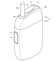
- FIG. 2 is an overall perspective view of the suction device 100 according to the present embodiment.
- FIG. 3 is an overall perspective view of the suction device 100 according to the present embodiment in a state where the stick-type base material 150 is held.
- the suction device 100 includes a top housing 11A, a bottom housing 11B, a cover 12, a switch 13, a lid 14, a vent 15, and a cap 16.
- the top housing 11A and the bottom housing 11B constitute the outermost outer housing 11 of the suction device 100 by being connected to each other.
- the outer housing 11 is sized to fit in a user's hand. When the user uses the suction device 100, the user can hold the suction device 100 in his/her hand and suction the flavor.
- the top housing 11A has an opening (not shown), and the cover 12 is coupled to the top housing 11A so as to close the opening.
- the cover 12 has an opening 142 into which a stick-type base material 150 can be inserted.
- the lid portion 14 is configured to open and close the opening 142 of the cover 12.
- the switch 13 is used to turn on and off the operation of the suction device 100.
- the user operates the switch 13 with the stick-shaped base material 150 inserted into the internal space 141 through the opening 142, so that power is supplied from the power supply section 111 to the heating section 121, and the stick It is possible to heat the mold base material 150 without burning it.
- the stick-type base material 150 is heated, an aerosol is generated from the aerosol source contained in the stick-type base material 150, and the flavor of the flavor source is incorporated into the aerosol.
- the user can suction the flavor-containing aerosol by suctioning the portion of the stick-type base material 150 that protrudes from the suction device 100 (the portion shown in FIG. 3, ie, the mouthpiece 152).
- the vent 15 is a vent for introducing air into the internal space 141. Air taken into the suction device 100 from the vent 15 is introduced into the internal space 141 from the bottom 143 of the housing section 140, for example.
- the cap 16 is configured to be detachably attached to the bottom housing 11B. By attaching the cap 16 to the bottom housing 11B, a vent 15 is formed between the bottom housing 11B and the cap 16.
- the cap 16 may have, for example, a through hole or a notch (not shown).
- FIG. 4 is a diagram schematically showing the configuration of the vicinity of the housing section 140 of the suction device 100 according to the present embodiment.
- the suction device 100 includes a lid part 14, a stick lower housing part 140A, a guide part 140B, an opening 142, a bottom part 143, an optical sensor part 170, and a circuit board 172.
- the direction in which the stick-type base material 150 is inserted into and removed from the suction device 100 is also referred to as the up-down direction.
- the direction in which the stick-type base material 150 is inserted is referred to as "down”
- the direction in which the stick-type base material 150 is removed is referred to as "up”.
- the stick lower accommodating part 140A is a bottomed cylindrical body that constitutes a part of the accommodating part 140 on the bottom 143 side.
- the stick lower accommodating portion 140A accommodates a portion of the stick-shaped base material 150 inserted into the internal space 141 from the opening 142 on the bottom 143 side.
- the guide portion 140B is a cylindrical body with openings at both ends, which constitutes a part of the accommodating portion 140 on the opening 142 side.
- the guide portion 140B accommodates the portion of the stick-shaped base material 150 inserted into the internal space 141 from the opening 142 that is accommodated in the accommodation portion 140 but is not accommodated in the stick lower accommodation portion 140A.
- the guide portion 140B functions as a guide to facilitate insertion of the stick-type base material 150 into the stick lower storage portion 140A.
- the guide portion 140B may have a diameter larger than that of the lower stick accommodating portion 140A, or may be configured in a funnel shape such that the diameter gradually decreases from top to bottom.
- the optical sensor section 170 emits light into the internal space 141 and detects the received reflected light.
- the optical sensor section 170 is an example of a detection section in this embodiment, and is included in the sensor section 112.
- the optical sensor section 170 is, for example, an IC (Integrated Circuit) equipped with an infrared proximity sensor.
- the optical sensor section 170 emits infrared rays into the internal space 141 and detects the infrared rays reflected by an object accommodated in the internal space 141 or an object to be detected, such as an inner wall of the accommodating section 140 .
- the optical sensor section 170 is arranged at a location where it can radiate light into the internal space 141.
- the optical sensor section 170 is arranged on the guide section 140B.
- the optical sensor section 170 is embedded in the guide section 140B.
- the optical sensor section 170 detects light reflected by an object accommodated in the internal space 141 or an object to be detected, such as an inner wall of the guide section 140B.
- the heating section 121 is arranged so as to cover the outer periphery of the stick lower accommodating section 140A.
- the heating section 121 is not arranged on the outer periphery of the guide section 140B.
- the guide portion 140B may be made of a material having lower thermal conductivity than the material forming the stick lower accommodating portion 140A. Therefore, the optical sensor section 170 can perform optical detection without being affected by the heating of the stick-type base material 150.
- the inner wall of the guide portion 140B may be black. By making the inner wall of the guide section 140B black, it is possible to suppress reflection of the light emitted by the optical sensor section 170.
- the stick-shaped base material 150 can be made of a color that reflects light relatively easily, such as white, the intensity of reflected light can be increased depending on whether the stick-shaped base material 150 is inserted or not. It can be made different.
- the circuit board 172 is a base on which the optical sensor section 170 is mounted.
- the circuit board 172 is, for example, an FPC (Flexible Printed Circuits) circuit.
- the circuit board 172 is connected to the control unit 116 by, for example, a connector or solder.
- FIG. 5 is a schematic diagram showing in detail the configuration of the vicinity of the optical sensor section 170 of the suction device 100 according to the present embodiment.
- the suction device 100 further includes a light transmission filter 173 and a reinforcing plate 174.
- the light transmission filter 173 is a filter that transmits the light emitted by the optical sensor section 170.
- the light transmission filter 173 is, for example, an infrared transmission filter when the optical sensor section 170 is an infrared proximity sensor.
- the material of the light transmission filter 173 is not particularly limited, and may be resin or glass, or may be a transparent resin coated with a light transmission coating.
- the light transmission filter 173 may be colored. By making the light transmission filter 173 colored, it is possible to hide the optical sensor section 170 from the outside.
- a hole 140Bb is provided in the inner wall 140Ba of the guide portion 140B, and the optical sensor portion 170 is disposed so as to be embedded in the hole 140Bb.
- the light transmission filter 173 is arranged so as to close the hole 140Bb, and forms an inner wall 140Ba of the guide portion 140B. According to this configuration, the inner wall 140Ba of the guide portion 140B can be made smooth. Moreover, according to the light transmission filter 173, it is possible to maintain airtightness so that sidestream smoke and the like flowing in from outside the stick do not come into contact with the optical sensor section 170.
- the clearance 175 is a gap provided between the stick-shaped base material 150 accommodated in the accommodation section 140 and the inner wall 140Ba of the guide section 140B.
- the clearance 175 may be provided such that the distance between the stick-shaped base material 150 and the inner wall 140Ba of the guide portion 140B is 1 to 2 mm.
- the reinforcing plate 174 is a plate-shaped member having a predetermined rigidity.
- the reinforcing plate 174 is arranged to cover the back side of the circuit board 172 on which the optical sensor section 170 is arranged on the front side, and reinforces the optical sensor section 170 and the circuit board 172.
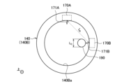
- FIG. 6 is a schematic diagram of the housing section 140 of the suction device 100 according to the present embodiment, viewed from the opening 142 side (ie, from above).
- the suction device 100 may have two optical sensor sections 170 (170A and 170B).
- the optical sensor section 170A and the optical sensor section 170B are arranged apart from each other, and the distance between them is LD .
- a direction 171A in which the optical sensor section 170A emits light hereinafter also referred to as the radiation direction 171A
- a direction 171B in which the optical sensor section 170B emits light hereinafter also referred to as the radiation direction 171B
- the plane forms an angle ⁇ .
- the suction device 100 has a plurality of optical sensor sections 170, and furthermore, by providing an appropriate distance LD and an appropriate angle ⁇ , it is possible to more accurately determine the article inserted into the storage section 140. It becomes possible. The determination process using the optical sensor section 170 will be described in detail later.
- FIG. 7 is a block diagram showing the configuration of the optical sensor section 170 in the suction device 100 according to the present embodiment.
- the optical sensor section 170 includes a light emitting section 176, a light receiving section 177, a detection storage section 178, and a detection control section 179.
- the optical sensor section 170 is then connected to the control section 116.
- the optical sensor section 170 operates under the control of the control section 116.
- the light emitting unit 176 emits light into the internal space 141.
- the light emitting section 176 is composed of a light emitting element such as an LD (Laser Diode) or an LED (Light Emitting Diode).
- the light emitting unit 176 is an infrared LD and emits infrared rays.
- the light receiving section 177 detects the reflected light of the light emitted by the light emitting section 176.
- the infrared rays emitted by the light emitting section 176 may be VCSEL (Vertical Cavity Surface Emitting Laser). The operation of the light emitting section 176 will be described in detail with reference to FIG. 8.
- FIG. 8 is a diagram showing an example of the operation of the optical sensor section 170 on the time axis.
- the horizontal axis in FIG. 8 indicates time, and time flows from left to right.
- the vertical axis in FIG. 8 indicates the intensity of light emitted by the light emitting section 176.
- the light emitting section 176 emits pulsed light at a predetermined period. The period is also called an operation period. After repeating pulsed light emission three times, the light emitting unit 176 stops emitting light during the processing time and the intermittent operation time.
- the processing time is the time during which processing based on the reflected light detected by the light receiving section 177 is performed.
- the intermittent operation time is the time until the next pulsed light emission is performed.
- the light emitting unit 176 repeatedly performs a series of operations including pulsed light emission and stopping of light emission described with reference to FIG. 8 .
- the detection control unit 179 controls the operation of each component of the optical sensor unit 170.
- An example of processing executed by the detection control unit 179 will be described below. These processes are basically executed during the processing time described with reference to FIG.
- the detection control unit 179 calculates a value indicating the intensity of the reflected light detected by the light receiving unit 177.
- the calculated value indicating the intensity of reflected light is also referred to as a detected value below.
- the detection control unit 179 calculates a larger detection value as the intensity of the detected reflected light is stronger.
- the relationship between the intensity of reflected light and the detected value may be linear.
- the detection control unit 179 calculates the distance to the detected object that reflects the light emitted from the optical sensor unit 170, that is, the distance between the detected object and the optical sensor unit 170, based on the detected value. You may. Specifically, the detection control unit 179 calculates a shorter distance as the detected value is larger, that is, the intensity of the reflected light is stronger. On the other hand, the detection control unit 179 calculates a longer distance as the detected value is smaller, that is, the intensity of the reflected light is weaker.
- the detection control section 179 controls the operation of the light emitting section 176.
- the detection control unit 179 may control at least one of the number of pulsed light emissions, the operation cycle, or the intermittent operation time shown in FIG.
- the detection control section 179 may control the intensity of infrared rays emitted by the light emitting section 176 by controlling the current value (hereinafter also referred to as LD current value) applied to the light emitting section 176.
- the detection control unit 179 notifies the control unit 116 of information.
- the detection control unit 179 may notify the control unit 116 of the calculated detection value.
- the detection control unit 179 may cause the detection storage unit 178 to store the calculated detection value.
- the detection control unit 179 may notify the control unit 116 to that effect.
- a notification will also be referred to as an interrupt notification below.
- the control unit 116 uses the reception of the interrupt notification as a trigger to read out the detection value stored in the detection storage unit 178.
- Such processing regarding the detected value may be similarly performed regarding the distance to the detected object.
- the detection control unit 179 may notify the control unit 116 of the calculated distance.
- the detection control unit 179 may store the calculated distance in the detection storage unit 178 and, when the calculated distance exceeds the notification threshold, notify the control unit 116 to that effect.
- the interruption notification may be a notification indicating that some article has been inserted into the storage section 140.
- the control unit 116 may execute a predetermined process using the reception of the interrupt notification as a trigger.
- An example of the predetermined process may include determining whether a stick determination condition described below is satisfied, heating control based on the determination result, and the like. According to this configuration, the predetermined process is executed only when an interrupt notification is received, so it is possible to reduce the processing load on the control unit 116.
- the detection control unit 179 may perform calibration. Specifically, the detection control unit 179 may adjust the relationship between the intensity of the reflected light detected by the light receiving unit 177 and the calculated detection value so that the same detection value is calculated under predetermined conditions. . By performing calibration, it is possible to eliminate deviations in detected values due to temperature or vibration, and to eliminate the effects of aging deterioration of the light emitting section 176 or the light receiving section 177.
- FIG. 8 shows an example in which the light emitting unit 176 emits pulsed light three times
- the number of pulsed light emissions is not particularly limited. Further, when the number of times of pulse emission by the light emitting unit 176 is multiple times, the detection control unit 179 may perform processing using the detection results by the light receiving unit 177 multiple times, or Processing may be performed using a part of the detection results obtained by 177.
- the detection storage unit 178 stores programs executed by the detection control unit 179 and various data.
- the detection storage unit 178 is an example of a storage unit in this embodiment.
- the detection storage unit 178 is realized, for example, by a register.
- the detection storage unit 178 stores various setting values used in control by the detection control unit 179, such as an operation cycle of infrared pulsed emission, an intermittent operation time, a notification threshold, and an LD current value.
- the control unit 116 and the detection control unit 179 communicate.
- the control unit 116 and the detection control unit 179 communicate, for example, through a serial communication interface such as I2C (Inter-Integrated Circuit) communication.
- the control unit 116 controls the operation of each component of the optical sensor unit 170 via the detection control unit 179.
- the control unit 116 controls the mode of the optical sensor unit 170 to be switched to an operation mode in which reflected light is detected or a sleep mode in which reflected light detection is stopped. Specifically, in the sleep mode, the control unit 116 controls the light emitting unit 176 to stop emitting light, and controls the light receiving unit 177 to stop detecting reflected light. Further, in the operation mode, the control unit 116 controls the light emitting unit 176 to emit light, and controls the light receiving unit 177 to detect reflected light. By controlling the mode switching of the optical sensor section 170 by the control section 116, it is possible to reduce power consumption compared to the case where the optical sensor section 170 constantly detects reflected light.
- control unit 116 causes the detection storage unit 178 to store various setting values used during control by the detection control unit 179. Further, the control unit 116 receives various information such as an interrupt notification from the detection control unit 179, and reads information stored in the detection storage unit 178.
- the detection storage unit 178 may be configured with a volatile storage medium or a nonvolatile storage medium.
- the various setting values stored in the detection storage section 178 are Initialized.
- the control unit 116 may cause the detection storage unit 178 to store the various setting values before initialization again.
- the control unit 116 may control the optical sensor unit 170 to enter a power-off mode in which power supply is stopped.
- the detection storage section 178 is configured with a volatile storage medium, and when controlling in this way, the control section 116 changes the initial state when switching the mode of the optical sensor section 170 from the power-off mode to the operation mode.
- the various setting values before conversion are stored in the detection storage section 178 again.
- the control unit 116 may control to maintain power supply to the detection storage unit 178 included in the optical sensor unit 170.
- the control unit 116 may control to maintain power supply to only a part of the memory of the detection storage unit 178 included in the optical sensor unit 170.
- deposits such as dirt or foreign matter may remain.
- the contents may spill from the tip of the heated stick-type base material 150 and remain in the internal space 141 as deposits.
- the housing section 140 be cleaned regularly. By removing the deposits through cleaning, it becomes possible to appropriately heat the stick-type base material 150, and as a result, it becomes possible to provide a good flavor to the user.
- An example of a cleaning article used to clean the housing section 140 will be described with reference to FIG. 9.
- FIG. 9 is a diagram showing an example of the configuration of the cotton swab 190 according to the present embodiment. As shown in FIG. 9, the cotton swab 190 has a shaft portion 191 and a fiber lump portion 192.
- the shaft portion 191 is a member configured in a longitudinal shape.
- the shaft portion 191 is constructed by winding a paper sheet.
- the fiber lump portion 192 is constructed by wrapping fibers around one end of the shaft portion 191 and bonding them.
- the fiber mass portion 192 may have any shape such as a teardrop shape, a cylindrical shape, a spherical shape, or a shape having random irregularities.
- Examples of the fibers constituting the fiber lump 192 include various natural fibers (cotton, silk, wool, etc.), regenerated fibers (rayon, cupro, etc.), synthetic fibers (polyester fibers, polypropylene fibers, etc.), and the like. Can be mentioned.
- the fiber lump portion 192 may contain a liquid such as alcohol. Note that the fiber lump portion 192 may be arranged at one end of the shaft portion 191 as shown in FIG. 9, or may be arranged at both ends of the shaft portion 191.
- the cotton swab 190 is an example of a cleaning article.
- the user grasps the shaft portion 191 and inserts the fiber mass portion 192 into the internal space 141 from the opening 142. Then, the user moves the fiber mass 192 so as to rub it against the housing section 140. Then, the deposits remaining in the accommodating portion 140 adhere to the fiber lump portion 192 and are removed. In this way, the storage section 140 is cleaned.
- the cotton swab 190 is thinner than the stick-type base material 150.
- the diameter of the cotton swab 190 (more specifically, the diameter of the fiber lump portion 192 which is the thickest part) L C is shorter than the diameter of the stick-type base material 150 (more specifically, the diameter of the thinnest part) L S configured.
- the diameter L C of the cotton swab 190 may be one-half or less, preferably one-quarter or less, of the diameter L S of the stick-type substrate 150 . According to this configuration, when the cotton swab 190 is inserted into the accommodating part 140, a large gap is ensured between the inner wall 140Ba of the guide part 140B and the cotton swab 190. As a result, the fiber lumps 192 can be freely moved in the internal space 141, and cleaning efficiency can be improved.
- the cotton swab 190 is an example of an article other than the stick-shaped base material 150 that is assumed to be inserted into the storage section 140.
- the suction device 100 and the cotton swab 190 may be considered to constitute an aerosol generation system.
- the suction device 100 may be understood to include the cotton swab 190.
- the difference between the diameter L C of the cotton swab 190 and the diameter L S of the stick-type base material 150 can also be used to identify an article inserted into the storage section 140 (hereinafter also referred to as an inserted article). This is because the detection values detected by the optical sensor section 170A and the optical sensor section 170B differ greatly depending on whether the inserted article is the stick-type base material 150 or the cotton swab 190. This point will be explained with reference to FIGS. 10 and 11.
- FIG. 10 is a diagram schematically showing the housing part 140 into which the stick-type base material 150 is inserted, viewed from the opening 142 side (ie, from above).
- the diameter L S of the stick-type base material 150 is longer than the distance L D between the optical sensor section 170A and the optical sensor section 170B.
- the distance between the stick-shaped base material 150 and the inner wall 140Ba of the guide portion 140B is about 1 to 2 mm. Therefore, as shown in FIG. 10, when the stick-type base material 150 is inserted into the accommodating part 140, any part of the inner wall 140Ba of the guide part 140B will be located at a close distance from the stick-type base material 150.
- the light emitted by either the optical sensor section 170A or the optical sensor section 170B is reflected by the stick-shaped base material 150 located at a close distance. Therefore, the detection value detected by the optical sensor section 170A and the detection value detected by the optical sensor section 170B are large and equal to each other.
- FIG. 11 is a diagram schematically showing the housing part 140 into which the cotton swab 190 is inserted, viewed from the opening 142 side (ie, from above).
- the diameter L C of the cotton swab 190 is significantly shorter than the distance L D between the optical sensor section 170A and the optical sensor section 170B. Therefore, as shown in FIG. 11, when the cotton swab 190 is inserted into the accommodating part 140, the distance between the inner wall 140Ba of the guide part 140B and the cotton swab 190 varies greatly depending on the position of the inner wall 140Ba.
- the detection value of at least one of the optical sensor section 170A and the optical sensor section 170B becomes significantly smaller than when the stick-shaped base material 150 is inserted into the accommodating section 140. This is because the position of at least one of the optical sensor section 170A or the optical sensor section 170B is far from the cotton swab 190, or the emitted light is not reflected by the cotton swab 190.
- the detection value of the optical sensor section 170B has the same magnitude as when the stick-type base material 150 is inserted, while the detection value of the optical sensor section 170A becomes significantly smaller.
- the control unit 116 determines whether the inserted article is the stick-type base material 150 based on the detection values detected by the two optical sensor units 170. As an example, the control unit 116 determines that the inserted article is the stick-type base material 150 when the stick determination condition is satisfied.
- An example of the stick determination condition is that both the detection value by the optical sensor section 170A and the detection value by the optical sensor section 170B are greater than or equal to a predetermined threshold value (hereinafter also referred to as a stick determination threshold value).
- a predetermined threshold value hereinafter also referred to as a stick determination threshold value
- the control unit 116 determines that the inserted article is not the stick-type base material 150 when at least one of the detection value by the optical sensor unit 170A and the detection value by the optical sensor unit 170B is less than the stick determination threshold. .
- the control unit 116 may determine that the inserted article is the cotton swab 190 when the stick determination condition is not satisfied.
- the stick determination threshold is arbitrarily set as a value at which the stick determination condition is satisfied when the inserted article is the stick type base material 150, and a value at which the stick determination condition is not satisfied when the inserted article is the cotton swab 190. That's fine.
- the diameter of the stick-type base material 150 may vary depending on the brand or production lot, or the stick-type base material 150 may have an irregular shape. Therefore, it is desirable that the stick determination threshold be set to a value with some margin (that is, a low value). Further, the stick determination threshold may be the same value as the notification threshold described above. According to this configuration, it is possible to determine whether the inserted article is the stick-type base material 150 or not.
- the optical sensor section 170A and the optical sensor section 170B are arranged at different positions. As a result, the optical sensor section 170A and the optical sensor section 170B can emit light to the inserted article from different positions and angles, respectively. According to this configuration, when the inserted article is the cotton swab 190, it is possible to prevent the stick determination condition from being satisfied. That is, it is possible to improve the accuracy of determining whether the inserted article is the stick-type base material 150 or not.
- the optical sensor section 170A and the optical sensor section 170B be spaced apart from each other by at least the diameter L C of the thickest part of the cotton swab 190 in a plane perpendicular to the vertical direction. That is, it is desirable that the distance LD between the optical sensor section 170A and the optical sensor section 170B be longer than the diameter LC of the fiber lump section 192.
- the cotton swab 190 when the cotton swab 190 is inserted into the accommodating portion 140, the cotton swab 190 can be prevented from being present in at least one of the radial direction 171A and the radial direction 171B.
- the stick determination condition can be prevented from being satisfied. That is, it is possible to improve the accuracy of determining whether the inserted article is the stick-type base material 150 or not.
- the optical sensor section 170A and the optical sensor section 170B have an angle ⁇ of 90 degrees or more and 270 degrees or less formed by the respective light emission directions 171A and 171B in a plane perpendicular to the vertical direction. It is desirable to place it in a position where . According to this configuration, it is possible to ensure a long distance LD between the optical sensor section 170A and the optical sensor section 170B. As a result, when the inserted article is the cotton swab 190, the stick determination condition can be prevented from being satisfied. That is, it is possible to improve the accuracy of determining whether the inserted article is the stick-type base material 150 or not.
- the optical sensor section 170A and the optical sensor section 170B may be arranged at positions where the angle ⁇ formed by the respective light emission directions 171A and 171B is other than 180 degrees in a plane orthogonal to the vertical direction. desirable. According to this configuration, it is possible to prevent crosstalk from occurring. Crosstalk is a phenomenon in which light emitted from either the optical sensor section 170A or the optical sensor section 170B is erroneously detected by the other. By preventing the occurrence of crosstalk, it is possible to prevent erroneous determination as to whether or not the inserted article is the stick-type base material 150.
- the control unit 116 may operate the optical sensor unit 170A and the optical sensor unit 170B at different timings. For example, the control unit 116 may operate the optical sensor unit 170A and the optical sensor unit 170B alternately. Specifically, in the example described above with reference to FIG. 8, the control unit 116 may cause the optical sensor unit 170A and the optical sensor unit 170B to alternately cause the optical sensor unit 170A and the optical sensor unit 170B to emit pulses three times each. According to this configuration, it is possible to more reliably prevent the occurrence of crosstalk.
- the control unit 116 may operate either the optical sensor unit 170A or the optical sensor unit 170B and put the other one to sleep.
- Operating the optical sensor section 170 refers to causing the optical sensor section 170 to detect reflected light.
- Putting the optical sensor unit 170 to sleep refers to stopping detection of reflected light by the optical sensor unit 170. That is, the control unit 116 may set one mode of the optical sensor unit 170A or the optical sensor unit 170B as an operation mode, and may set the other mode as a sleep mode or a power-off mode.
- the control unit 116 interrupts the sleep state of the other optical sensor unit 170A or the optical sensor unit 170B and starts the operation only when the detected value by one of the optical sensor units 170A or 170B that is in operation becomes equal to or higher than the stick determination threshold.
- the control unit 116 interrupts the sleep state of the other optical sensor unit 170A or the optical sensor unit 170B and starts the operation only when the detected value by one of the optical sensor units 170A or 170B that is in operation becomes equal to or higher than the stick determination threshold.
- both the optical sensor section 170A and the optical sensor section 170B are operated only when some kind of article is inserted into the storage section 140, and it is determined whether the inserted article is the stick-type base material 150 or not. be able to. Therefore, it is possible to suppress power consumption.
- the optical sensor section 170A or the optical sensor section 170B is in sleep mode, it is possible to reliably prevent crosstalk from occurring.
- the optical sensor section 170A and the optical sensor section 170B may be arranged at positions where the angle ⁇ formed by the respective light emission directions 171A and 171B is 180 degrees in a plane orthogonal to the vertical direction. Even in that case, crosstalk can be prevented if the above-mentioned crosstalk prevention measures are taken. Furthermore, with this configuration, the distance LD between the optical sensor section 170A and the optical sensor section 170B can be made the longest. As a result, when the inserted article is the cotton swab 190, the stick determination condition can be prevented from being satisfied. That is, it is possible to improve the accuracy of determining whether the inserted article is the stick-type base material 150 or not.
- the control unit 116 may control the operation of the heating unit 121 based on the determination result of whether the inserted article is the stick-type base material 150. Specifically, the control unit 116 causes the heating unit 121 to operate differently depending on whether the inserted article is the stick-type base material 150 or not. According to this configuration, it is possible to further improve usability.
- control unit 116 may cause the heating unit 121 to start heating.
- control unit 116 determines that the inserted article is not the stick-type base material 150
- the control unit 116 does not cause the heating unit 121 to start heating. That is, the control unit 116 may automatically start heating only when the stick-type base material 150 is inserted. According to this configuration, heating is automatically started simply by inserting the stick-shaped base material 150 into the housing part 140 without the need for a separate user operation such as pressing a button to instruct the start of heating, thereby improving usability. It becomes possible to do so.
- control unit 116 allows heating by the heating unit 121 when determining that the inserted article is the stick-type base material 150, and allows heating by the heating unit 121 when determining that the inserted article is not the stick-type base material 150.
- Heating by 121 may be prohibited.
- the suction device 100 starts heating when a user operation instructing to start heating, such as pressing a button, is performed.
- the suction device 100 does not start heating even if a user operation instructing to start heating, such as pressing a button, is performed. According to this configuration, heating does not start even if a button is pressed incorrectly during cleaning, so it is possible to improve user safety.
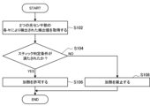
- FIG. 12 is a flowchart showing an example of the flow of processing executed by the suction device 100 according to the present embodiment.
- the control unit 116 obtains the detection values detected by each of the two optical sensor units 170 (step S102). For example, when the control unit 116 receives an interrupt notification from either one of the two optical sensor units 170 as a trigger, the control unit 116 reads out the detection value stored in the detection storage unit 178 of each of the two optical sensor units 170. .
- control unit 116 determines whether the stick determination condition is satisfied (step S104). Specifically, the control unit 116 determines whether both the detection value by the optical sensor unit 170A and the detection value by the optical sensor unit 170B are equal to or greater than the stick determination threshold.
- step S104 If it is determined that the stick determination condition is satisfied (step S104: YES), the control unit 116 permits heating by the heating unit 121 (step S106).
- step S104 determines that the stick determination condition is not satisfied.
- step S108 the control unit 116 prohibits heating by the heating unit 121 (step S108).
- the suction device 100 has two optical sensor sections 170
- the present disclosure is not limited to such an example. Good too. In that case, it is sufficient that the above-described positional relationship is satisfied for at least two of the three or more optical sensor sections 170.
- the control unit 116 may determine the shape characteristics of the inserted article based on the detection value detected by the optical sensor unit 170.
- An example of a shape characteristic is the diameter of the insert. That is, it may be determined whether the diameter of the inserted article is equivalent to the diameter of the stick-shaped substrate 150.
- the stick determination condition is related to a detection value detected by the optical sensor section 170, but the present disclosure is not limited to such an example.
- the stick determination condition may be related to the distance to the detected object calculated based on the detected value.
- the first condition may be that the stick determination condition is that both the distance from the optical sensor section 170A to the detected object and the distance from the optical sensor section 170B to the detected object are less than a predetermined distance.
- the predetermined distance may be set as a distance corresponding to the stick determination threshold.
- Such a configuration also makes it possible to determine whether the inserted article is the stick-type base material 150 or not.
- optical sensor section 170A and the optical sensor section 170B are arranged at different positions on a plane perpendicular to the vertical direction, but the present disclosure is not limited to such an example.
- the optical sensor section 170A and the optical sensor section 170 may be arranged at different positions in the vertical direction instead of being arranged at different positions in the plane orthogonal to the up-down direction, or both may be arranged at different positions in the up-down direction.
- the optical sensor section 170A may be arranged on the opening 142 side of the guide section 140B, and the optical sensor section 170B may be arranged on the bottom section 143 side of the guide section 140B.
- the optical sensor section 170A and the optical sensor section 170B are arranged at different positions in the vertical direction, the radiation direction 171A and the radiation direction 171B can be prevented from intersecting. Therefore, it is possible to further improve the accuracy of determining whether the inserted article is the stick-type base material 150 or not.
- the optical sensor section 170A and the optical sensor section 170B are arranged at different positions in the vertical direction, it becomes possible to identify changes in the thickness of the inserted article in the vertical direction. Therefore, even if there is a part in the vertical direction of the cleaning article that has the same thickness as the stick-type base material 150, it is determined whether the inserted article is the stick-type base material 150 or the cleaning article. It is possible to do so. However, it is assumed that the distance in the vertical direction between the optical sensor section 170A and the optical sensor section 170B is longer than the length in the vertical direction of the portion of the cleaning article that has the same thickness as the stick-shaped base material 150. .
- the two optical sensor sections 170 may be arranged at positions where at least a portion thereof overlaps each other in the vertical direction.
- the range in which the optical sensor section 170 can be arranged in the guide section 140B is considered to be limited.
- heat transfer from the heating section 121 to the optical sensor section 170 can be prevented by arranging both of the two optical sensor sections 170 on the side of the opening 142 that is farther from the heating section 121. becomes possible.
- the control unit 116 may determine whether the inserted article is the stick-type base material 150 based on a plurality of detection values detected at different timings by the same optical sensor unit 170. As an example, the control unit 116 may determine that the inserted article is the stick-shaped base material 150 when the width of the time-series change in the value detected by the optical sensor unit 170 is less than a predetermined threshold. When the inserted article is the stick-type base material 150, the stick-type base material 150 does not move much within the storage section 140, so it is assumed that the time-series change in the value detected by the optical sensor section 170 is small. It is.
- control unit 116 may determine that the inserted article is not the stick-shaped base material 150 when the width of the time-series change in the value detected by the optical sensor unit 170 is equal to or greater than a predetermined threshold. This is because when the inserted article is the cotton swab 190, the user moves the cotton swab 190 a lot within the storage section 140, so the value detected by the optical sensor section 170 is expected to change greatly over time. According to this configuration, it is possible to improve the accuracy of determining whether the inserted article is the stick-type base material 150 or not.
- the number of optical sensor units 170 that the suction device 100 has may be one.
- the time-series change in the detected value corresponds to the change in the vertical thickness of the inserted article. Therefore, even if there is a part in the vertical direction of the cleaning article that has the same thickness as the stick-type base material 150, it is difficult to determine whether the inserted article is the stick-type base material 150 or the cleaning article. It is possible to make a determination based on time-series changes in detected values.
- each device described in this specification may be realized using software, hardware, or a combination of software and hardware.
- a program constituting the software is stored in advance, for example, in a recording medium (specifically, a computer-readable non-temporary storage medium) provided inside or outside each device.
- each program is read into the RAM when executed by a computer that controls each device described in this specification, and is executed by a processing circuit such as a CPU.
- the recording medium is, for example, a magnetic disk, an optical disk, a magneto-optical disk, a flash memory, or the like.
- the above computer program may be distributed, for example, via a network, without using a recording medium.
- the above-mentioned computer may be an application-specific integrated circuit such as an ASIC, a general-purpose processor that executes functions by loading a software program, or a computer on a server used for cloud computing. Furthermore, a series of processes performed by each device described in this specification may be distributed and processed by multiple computers.
- an accommodating portion having an internal space and an opening that communicates the internal space with the outside; one or more detection units that emit light into the internal space and detect the received reflected light; a control unit that determines whether the article inserted into the storage unit is a substrate containing an aerosol source based on the intensity of the plurality of reflected lights detected by one or more of the detection units; an aerosol generation system.
- the aerosol generation system further includes a heating section that heats the base material accommodated in the accommodation section, The control unit controls the operation of the heating unit based on a determination result of whether the article inserted into the storage unit is the base material.
- the control unit causes the heating unit to start heating when determining that the article inserted into the storage unit is the base material.
- the control unit allows heating by the heating unit when determining that the article inserted into the housing section is the base material, and when determining that the article inserted into the housing section is not the base material. prohibiting heating by the heating section, The aerosol generation system according to (2) above.
- the aerosol generation system includes the two detection units, The two detection units are arranged at mutually different positions, The aerosol generation system according to any one of (1) to (4) above. (6)
- the control unit operates each of the two detection units at mutually different timings, The aerosol generation system according to (5) above.
- the control unit operates one of the two detection units and puts the other one to sleep.
- the two detection units are arranged at mutually different positions in the insertion direction of the base material, The aerosol generation system according to any one of (5) to (7) above.
- the two detection units are arranged at positions at least partially overlapping each other in the insertion direction of the base material, The aerosol generation system according to any one of (5) to (7) above.
- the two detection parts are arranged at a distance equal to or more than the diameter of the thickest part of the article other than the base material, which is assumed to be inserted into the storage part.
- the two detection units are arranged at positions where the angle formed by the light emitting direction is 90 degrees or more and 270 degrees or less in a plane perpendicular to the insertion direction of the base material.
- the two detection units are arranged at positions where the angle formed by the light emitting direction is 180 degrees in a plane perpendicular to the insertion direction of the base material.
- the control unit determines whether the article inserted into the storage unit is the base material based on the intensity of a plurality of reflected lights detected at different timings by the same detection unit.
- the aerosol generation system according to any one of (1) to (12) above.
- the aerosol generation system further includes at least one of the base material or an article other than the base material that is expected to be inserted into the accommodating part.
- the aerosol generation system according to any one of (1) to (13) above.
- (15) Intensity of a plurality of reflected lights detected by one or more detection units that emit light into the internal space of a housing unit having an internal space and an opening that communicates the internal space with the outside, and detect the received reflected light. determining whether the article inserted into the storage part is a substrate containing an aerosol source based on;
- An information processing method performed by a computer including:
- Suction device 111 Power supply section 112 Sensor section 113 Notification section 114 Storage section 115 Communication section 116 Control section 121 Heating section 140 Storage section 140A Stick lower storage section 140B Guide section 141 Internal space 142 Opening 143 Bottom section 144 Heat insulation section 150 Stick type base material 170 Optical sensor section 172 Circuit board 173 Light transmission filter 174 Reinforcement plate 175 Clearance 176 Light emitting section 177 Light receiving section 178 Detection storage section 179 Detection control section 190 Cotton swab 191 Shaft section 192 Fiber lump section
Landscapes
- Investigating Or Analysing Materials By Optical Means (AREA)
Abstract
[Problem] To provide a mechanism capable of further improving the quality of user experience. [Solution] Provided is an aerosol generation system provided with: a storage unit that has an internal space and an opening through which the internal space is communicated with the outside; at least one detection unit that emits light toward the internal space and detects received reflected light; and a control unit that determines whether or not an article inserted into the storage unit is a base material containing an aerosol source on the basis of the intensities of a plurality of reflected lights detected by the at least one detection unit.
Description
本開示は、エアロゾル生成システム、及び情報処理方法に関する。
The present disclosure relates to an aerosol generation system and an information processing method.
電子タバコ及びネブライザ等の、ユーザに吸引される物質を生成する吸引装置が広く普及している。例えば、吸引装置は、エアロゾルを生成するためのエアロゾル源、及び生成されたエアロゾルに香味成分を付与するための香味源等を含む基材を用いて、香味成分が付与されたエアロゾルを生成する。ユーザは、吸引装置により生成された、香味成分が付与されたエアロゾルを吸引することで、香味を味わうことができる。ユーザがエアロゾルを吸引する動作を、以下ではパフ又はパフ動作とも称する。
Inhalation devices, such as electronic cigarettes and nebulizers, that produce substances that are inhaled by a user are widespread. For example, a suction device generates an aerosol to which a flavor component has been added using a base material that includes an aerosol source for generating an aerosol, a flavor source for imparting a flavor component to the generated aerosol, and the like. The user can taste the flavor by inhaling the aerosol to which the flavor component is added, which is generated by the suction device. The action of the user inhaling an aerosol will also be referred to below as a puff or a puff action.
このような吸引装置を使用する際のユーザ体験の質のさらなる向上を目指して、様々な技術開発が行われている。例えば、下記特許文献1では、光を放射し、反射光のリン光特性を検出し、当該検出結果に基づいて吸引装置の動作を制御する技術が開示されている。
Various technological developments are being carried out with the aim of further improving the quality of the user experience when using such suction devices. For example, Patent Document 1 listed below discloses a technique of emitting light, detecting the phosphorescence characteristics of the reflected light, and controlling the operation of a suction device based on the detection result.
上記特許文献1に開示されているように、基材を加熱する際の温度制御は、香味の向上に寄与し得る。他に、吸引装置を清掃することも、香味の向上に寄与する。しかしながら、吸引装置の清掃に関しては、上記特許文献1では何ら言及されていなかった。
As disclosed in Patent Document 1, temperature control when heating the base material can contribute to improving flavor. Additionally, cleaning the suction device also contributes to improving the flavor. However, the above Patent Document 1 does not mention anything about cleaning the suction device.
そこで、本開示は、上記問題に鑑みてなされたものであり、本開示の目的とするところは、ユーザ体験の質をより向上させることが可能な仕組みを提供することにある。
Therefore, the present disclosure has been made in view of the above problems, and the purpose of the present disclosure is to provide a mechanism that can further improve the quality of user experience.
上記課題を解決するために、本開示のある観点によれば、内部空間及び前記内部空間を外部に連通する開口を有する収容部と、前記内部空間に光を放射し、受光した反射光を検出する1つ以上の検出部と、1つ以上の前記検出部によって検出された複数の反射光の強度に基づいて、前記収容部に挿入された物品がエアロゾル源を含有した基材であるか否かを判定する制御部と、を備える、エアロゾル生成システムが提供される。
In order to solve the above problems, according to a certain aspect of the present disclosure, there is provided an accommodating portion having an internal space and an opening that communicates the internal space to the outside, and a housing unit that emits light into the internal space and detects the received reflected light. and one or more detection units that detect whether the article inserted into the storage unit is a substrate containing an aerosol source based on the intensity of the plurality of reflected lights detected by the one or more detection units. An aerosol generation system is provided, comprising: a control unit that determines whether
前記エアロゾル生成システムは、前記収容部に収容された前記基材を加熱する加熱部をさらに備え、前記制御部は、前記収容部に挿入された物品が前記基材であるか否かの判定結果に基づいて前記加熱部の動作を制御してもよい。
The aerosol generation system further includes a heating unit that heats the base material accommodated in the accommodating unit, and the control unit controls the determination result of whether the article inserted into the accommodating unit is the base material. The operation of the heating section may be controlled based on.
前記制御部は、前記収容部に挿入された物品が前記基材であると判定した場合に、前記加熱部による加熱を開始させてもよい。
The control unit may cause the heating unit to start heating when determining that the article inserted into the storage unit is the base material.
前記制御部は、前記収容部に挿入された物品が前記基材であると判定した場合に前記加熱部による加熱を許可し、前記収容部に挿入された物品が前記基材でないと判定した場合に前記加熱部による加熱を禁止してもよい。
The control unit allows heating by the heating unit when determining that the article inserted into the housing section is the base material, and when determining that the article inserted into the housing section is not the base material. Heating by the heating section may also be prohibited.
前記エアロゾル生成システムは、2つの前記検出部を備え、2つの前記検出部は互いに異なる位置に配置されてもよい。
The aerosol generation system may include the two detection units, and the two detection units may be arranged at different positions.
前記制御部は、2つの前記検出部の各々を互いに異なるタイミングで動作させてもよい。
The control section may operate each of the two detection sections at different timings.
前記制御部は、2の前記検出部のうち一方を動作させ他方をスリープさせてもよい。
The control section may operate one of the two detection sections and put the other one to sleep.
2つの前記検出部は、前記基材の挿入方向において互いに異なる位置に配置されてもよい。
The two detection units may be arranged at different positions in the insertion direction of the base material.
2つの前記検出部は、前記基材の挿入方向において少なくとも一部が互いに重複する位置に配置されてもよい。
The two detection units may be arranged at least partially overlapping each other in the insertion direction of the base material.
2つの前記検出部は、前記収容部に挿入されることが想定される、前記基材以外の物品の最も太い部分の直径以上に離隔して配置されてもよい。
The two detection parts may be arranged at a distance greater than or equal to the diameter of the thickest part of an article other than the base material that is expected to be inserted into the storage part.
2つの前記検出部は、前記基材の挿入方向に直交する面において、光を放射する方向が成す角度が90度以上270度以下となる位置に配置されてもよい。
The two detection units may be arranged at positions where the angle formed by the light emitting direction is greater than or equal to 90 degrees and less than or equal to 270 degrees in a plane perpendicular to the insertion direction of the base material.
2つの前記検出部は、前記基材の挿入方向に直交する面において、光を放射する方向が成す角度が180度となる位置に配置されてもよい。
The two detection units may be arranged at positions where the angle formed by the light emitting direction is 180 degrees in a plane perpendicular to the insertion direction of the base material.
前記制御部は、同一の前記検出部により異なるタイミングで検出された複数の反射光の強度に基づいて、前記収容部に挿入された物品が前記基材であるか否かを判定してもよい。
The control unit may determine whether the article inserted into the storage unit is the base material based on the intensity of a plurality of reflected lights detected at different timings by the same detection unit. .
前記エアロゾル生成システムは、前記基材、又は前記収容部に挿入されることが想定される前記基材以外の物品の少なくともいずれか1つをさらに備えてもよい。
The aerosol generation system may further include at least one of the base material or an article other than the base material that is expected to be inserted into the storage section.
また、上記課題を解決するために、本開示の別の観点によれば、内部空間及び前記内部空間を外部に連通する開口を有する収容部の前記内部空間に光を放射し、受光した反射光を検出する1つ以上の検出部によって検出された、複数の反射光の強度に基づいて、前記収容部に挿入された物品がエアロゾル源を含有した基材であるか否かを判定することと、を含む、コンピュータにより実行される情報処理方法が提供される。
Moreover, in order to solve the above-mentioned problem, according to another aspect of the present disclosure, light is emitted into the internal space of a housing section that has an internal space and an opening that communicates the internal space with the outside, and the reflected light that is received is Determining whether the article inserted into the storage part is a substrate containing an aerosol source based on the intensity of the plurality of reflected lights detected by one or more detection parts that detect An information processing method performed by a computer is provided, including the following.
以上説明したように本開示によれば、ユーザ体験の質をより向上させることが可能な仕組みが提供される。
As explained above, according to the present disclosure, a mechanism that can further improve the quality of user experience is provided.
以下に添付図面を参照しながら、本開示の好適な実施の形態について詳細に説明する。なお、本明細書及び図面において、実質的に同一の機能構成を有する構成要素については、同一の符号を付することにより重複説明を省略する。
Preferred embodiments of the present disclosure will be described in detail below with reference to the accompanying drawings. Note that, in this specification and the drawings, components having substantially the same functional configurations are designated by the same reference numerals and redundant explanation will be omitted.
また、本明細書及び図面において、実質的に同一の機能構成を有する要素を、同一の符号の後に異なるアルファベットを付して区別する場合もある。例えば、実質的に同一の機能構成を有する複数の要素を、必要に応じて光センサ部170A及び光センサ部170Bのように区別する。ただし、実質的に同一の機能構成を有する複数の要素の各々を特に区別する必要がない場合、同一符号のみを付する。例えば、光センサ部170A及び光センサ部170Bを特に区別する必要が無い場合には、単に光センサ部170と称する。
Furthermore, in this specification and drawings, elements having substantially the same functional configuration may be distinguished by using different alphabets after the same reference numerals. For example, a plurality of elements having substantially the same functional configuration may be distinguished as the optical sensor section 170A and the optical sensor section 170B, if necessary. However, if there is no particular need to distinguish each of a plurality of elements having substantially the same functional configuration, only the same reference numerals are given. For example, if there is no need to particularly distinguish between the optical sensor section 170A and the optical sensor section 170B, they will simply be referred to as the optical sensor section 170.
<1.吸引装置の構成例>
(1)内部構成例
図1は、吸引装置の内部構成例を模式的に示す模式図である。図1に示すように、本構成例に係る吸引装置100は、電源部111、センサ部112、通知部113、記憶部114、通信部115、制御部116、加熱部121、収容部140、及び断熱部144を含む。 <1. Configuration example of suction device>
(1) Internal configuration example FIG. 1 is a schematic diagram schematically showing an internal configuration example of a suction device. As shown in FIG. 1, thesuction device 100 according to this configuration example includes a power supply section 111, a sensor section 112, a notification section 113, a storage section 114, a communication section 115, a control section 116, a heating section 121, a housing section 140, and A heat insulating section 144 is included.
(1)内部構成例
図1は、吸引装置の内部構成例を模式的に示す模式図である。図1に示すように、本構成例に係る吸引装置100は、電源部111、センサ部112、通知部113、記憶部114、通信部115、制御部116、加熱部121、収容部140、及び断熱部144を含む。 <1. Configuration example of suction device>
(1) Internal configuration example FIG. 1 is a schematic diagram schematically showing an internal configuration example of a suction device. As shown in FIG. 1, the
電源部111は、電力を蓄積する。そして、電源部111は、制御部116による制御に基づいて、吸引装置100の各構成要素に電力を供給する。電源部111は、例えば、リチウムイオン二次電池等の充電式バッテリにより構成され得る。
The power supply unit 111 stores power. Then, the power supply unit 111 supplies power to each component of the suction device 100 based on control by the control unit 116. The power supply unit 111 may be configured with a rechargeable battery such as a lithium ion secondary battery, for example.
センサ部112は、吸引装置100に関する各種情報を取得する。一例として、センサ部112は、コンデンサマイクロホン等の圧力センサ、流量センサ又は温度センサ等により構成され、ユーザによる吸引に伴う値を取得する。他の一例として、センサ部112は、ボタン又はスイッチ等の、ユーザからの情報の入力を受け付ける入力装置により構成される。
The sensor unit 112 acquires various information regarding the suction device 100. As an example, the sensor unit 112 includes a pressure sensor such as a condenser microphone, a flow rate sensor, a temperature sensor, etc., and acquires a value associated with suction by the user. As another example, the sensor unit 112 is configured with an input device such as a button or a switch that receives information input from the user.
通知部113は、情報をユーザに通知する。通知部113は、例えば、発光する発光装置、画像を表示する表示装置、音を出力する音出力装置、又は振動する振動装置等により構成される。
The notification unit 113 notifies the user of information. The notification unit 113 includes, for example, a light emitting device that emits light, a display device that displays an image, a sound output device that outputs sound, a vibration device that vibrates, or the like.
記憶部114は、吸引装置100の動作のための各種情報を記憶する。記憶部114は、例えば、フラッシュメモリ等の不揮発性の記憶媒体により構成される。
The storage unit 114 stores various information for the operation of the suction device 100. The storage unit 114 is configured by, for example, a nonvolatile storage medium such as a flash memory.
通信部115は、有線又は無線の任意の通信規格に準拠した通信を行うことが可能な通信インタフェースである。かかる通信規格としては、例えば、Wi-Fi(登録商標)、Bluetooth(登録商標)、BLE(Bluetooth Low Energy(登録商標))、NFC(Near Field Communication)、又はLPWA(Low Power Wide Area)を用いる規格等が採用され得る。
The communication unit 115 is a communication interface that can perform communication compliant with any wired or wireless communication standard. Such communication standards include, for example, Wi-Fi (registered trademark), Bluetooth (registered trademark), BLE (Bluetooth Low Energy (registered trademark)), NFC (Near Field Communication), or LPWA (Low Power Wide Area). Standards etc. may be adopted.
制御部116は、演算処理装置及び制御装置として機能し、各種プログラムに従って吸引装置100内の動作全般を制御する。制御部116は、例えばCPU(Central Processing Unit)、又はマイクロプロセッサ等の電子回路によって実現される。
The control unit 116 functions as an arithmetic processing device and a control device, and controls overall operations within the suction device 100 according to various programs. The control unit 116 is realized by, for example, an electronic circuit such as a CPU (Central Processing Unit) or a microprocessor.
収容部140は、内部空間141を有し、内部空間141にスティック型基材150の一部を収容しながらスティック型基材150を保持する。収容部140は、内部空間141を外部に連通する開口142を有し、開口142から内部空間141に挿入されたスティック型基材150を収容する。例えば、収容部140は、開口142及び底部143を底面とする筒状体であり、柱状の内部空間141を画定する。収容部140には、内部空間141に空気を供給する空気流路が接続される。空気流路への空気の入口である空気流入孔は、例えば、吸引装置100の側面に配置される。空気流路から内部空間141への空気の出口である空気流出孔は、例えば、底部143に配置される。
The accommodating part 140 has an internal space 141, and holds the stick-type base material 150 while accommodating a part of the stick-type base material 150 in the internal space 141. The accommodating part 140 has an opening 142 that communicates the internal space 141 with the outside, and accommodates the stick-shaped base material 150 inserted into the internal space 141 from the opening 142. For example, the accommodating portion 140 is a cylindrical body having an opening 142 and a bottom portion 143 as a bottom surface, and defines a columnar internal space 141 . An air flow path that supplies air to the internal space 141 is connected to the housing section 140 . An air inflow hole, which is an inlet of air to the air flow path, is arranged on a side surface of the suction device 100, for example. An air outlet hole, which is an outlet for air from the air flow path to the internal space 141, is arranged at the bottom 143, for example.
スティック型基材150は、基材部151、及び吸口部152を含む。基材部151は、エアロゾル源を含む。エアロゾル源は、たばこ由来又は非たばこ由来の香味成分を含む。吸引装置100がネブライザ等の医療用吸入器である場合、エアロゾル源は、薬剤を含んでもよい。エアロゾル源は、例えば、たばこ由来又は非たばこ由来の香味成分を含む、グリセリン及びプロピレングリコール等の多価アルコール、並びに水等の液体であってもよく、たばこ由来又は非たばこ由来の香味成分を含む固体であってもよい。スティック型基材150が収容部140に保持された状態において、基材部151の少なくとも一部は内部空間141に収容され、吸口部152の少なくとも一部は開口142から突出する。そして、開口142から突出した吸口部152をユーザが咥えて吸引すると、図示しない空気流路を経由して内部空間141に空気が流入し、基材部151から発生するエアロゾルと共にユーザの口内に到達する。
The stick-type base material 150 includes a base portion 151 and a mouthpiece portion 152. Base portion 151 includes an aerosol source. The aerosol source includes flavor components of tobacco or non-tobacco origin. If the suction device 100 is a medical inhaler, such as a nebulizer, the aerosol source may include a drug. The aerosol source may be, for example, a liquid such as polyhydric alcohols such as glycerin and propylene glycol, and water, containing flavor components of tobacco or non-tobacco origin, and containing flavor components of tobacco or non-tobacco origin. It may be solid. In a state where the stick-shaped base material 150 is held in the housing section 140, at least a portion of the base material section 151 is accommodated in the internal space 141, and at least a portion of the mouthpiece section 152 protrudes from the opening 142. When the user holds the mouthpiece 152 protruding from the opening 142 and sucks it, air flows into the internal space 141 via an air flow path (not shown) and reaches the user's mouth together with the aerosol generated from the base member 151. do.
加熱部121は、エアロゾル源を加熱することで、エアロゾル源を霧化してエアロゾルを生成する。図1に示した例では、加熱部121は、フィルム状に構成され、収容部140の外周を覆うように配置される。そして、加熱部121が発熱すると、スティック型基材150の基材部151が外周から加熱され、エアロゾルが生成される。加熱部121は、電源部111から給電されると発熱する。一例として、ユーザが吸引を開始したこと、及び/又は所定の情報が入力されたことが、センサ部112により検出された場合に、給電されてもよい。そして、ユーザが吸引を終了したこと、及び/又は所定の情報が入力されたことが、センサ部112により検出された場合に、給電が停止されてもよい。
The heating unit 121 atomizes the aerosol source to generate aerosol by heating the aerosol source. In the example shown in FIG. 1, the heating section 121 is configured in a film shape and is arranged to cover the outer periphery of the housing section 140. Then, when the heating section 121 generates heat, the base material section 151 of the stick-type base material 150 is heated from the outer periphery, and an aerosol is generated. The heating unit 121 generates heat when supplied with power from the power supply unit 111 . As an example, power may be supplied when the sensor unit 112 detects that the user has started suctioning and/or that predetermined information has been input. Then, when the sensor unit 112 detects that the user has finished suctioning and/or that predetermined information has been input, the power supply may be stopped.
断熱部144は、加熱部121から他の構成要素への伝熱を防止する。例えば、断熱部144は、真空断熱材、又はエアロゲル断熱材等により構成される。
The heat insulating section 144 prevents heat transfer from the heating section 121 to other components. For example, the heat insulating section 144 is made of a vacuum heat insulating material, an airgel heat insulating material, or the like.
以上、吸引装置100の構成例を説明した。もちろん吸引装置100の構成は上記に限定されず、以下に例示する多様な構成をとり得る。
The configuration example of the suction device 100 has been described above. Of course, the configuration of the suction device 100 is not limited to the above, and may take various configurations as exemplified below.
一例として、加熱部121は、ブレード状に構成され、収容部140の底部143から内部空間141に突出するように配置されてもよい。その場合、ブレード状の加熱部121は、スティック型基材150の基材部151に挿入され、スティック型基材150の基材部151を内部から加熱する。他の一例として、加熱部121は、収容部140の底部143を覆うように配置されてもよい。また、加熱部121は、収容部140の外周を覆う第1の加熱部、ブレード状の第2の加熱部、及び収容部140の底部143を覆う第3の加熱部のうち、2以上の組み合わせとして構成されてもよい。
As an example, the heating section 121 may be configured in a blade shape and arranged to protrude from the bottom 143 of the housing section 140 into the internal space 141. In that case, the blade-shaped heating unit 121 is inserted into the base portion 151 of the stick-type base material 150 and heats the base portion 151 of the stick-type base material 150 from inside. As another example, the heating part 121 may be arranged to cover the bottom part 143 of the housing part 140. The heating unit 121 is a combination of two or more of a first heating unit that covers the outer periphery of the housing unit 140, a blade-shaped second heating unit, and a third heating unit that covers the bottom portion 143 of the housing unit 140. It may be configured as
他の一例として、収容部140は、内部空間141を形成する外殻の一部を開閉する、ヒンジ等の開閉機構を含んでいてもよい。そして、収容部140は、外殻を開閉することで、内部空間141に挿入されたスティック型基材150を挟持しながら収容してもよい。その場合、加熱部121は、収容部140における当該挟持箇所に設けられ、スティック型基材150を押圧しながら加熱してもよい。
As another example, the accommodating portion 140 may include an opening/closing mechanism such as a hinge that opens and closes a part of the outer shell forming the internal space 141. The accommodating part 140 may accommodate the stick-shaped base material 150 inserted into the internal space 141 while sandwiching it by opening and closing the outer shell. In that case, the heating unit 121 may be provided at the relevant clamping location in the storage unit 140 and may heat the stick-shaped base material 150 while pressing it.
また、エアロゾル源を霧化する手段は、加熱部121による加熱に限定されない。例えば、エアロゾル源を霧化する手段は、誘導加熱であってもよい。
Further, the means for atomizing the aerosol source is not limited to heating by the heating unit 121. For example, the means of atomizing the aerosol source may be induction heating.
なお、吸引装置100とスティック型基材150とは協同してエアロゾルを生成する、エアロゾル生成システムを構成すると捉えられてもよい。若しくは、吸引装置100は、スティック型基材150を含むと捉えられてもよい。
Note that the suction device 100 and the stick-type base material 150 may be considered to constitute an aerosol generation system that generates aerosol in cooperation. Alternatively, the suction device 100 may be considered to include the stick-type base material 150.
(2)外観構成例
図2は、本実施形態に係る吸引装置100の全体斜視図である。図3は、スティック型基材150を保持した状態の本実施形態に係る吸引装置100の全体斜視図である。 (2) External configuration example FIG. 2 is an overall perspective view of thesuction device 100 according to the present embodiment. FIG. 3 is an overall perspective view of the suction device 100 according to the present embodiment in a state where the stick-type base material 150 is held.
図2は、本実施形態に係る吸引装置100の全体斜視図である。図3は、スティック型基材150を保持した状態の本実施形態に係る吸引装置100の全体斜視図である。 (2) External configuration example FIG. 2 is an overall perspective view of the
図2および図3に示すように、吸引装置100は、トップハウジング11Aと、ボトムハウジング11Bと、カバー12と、スイッチ13と、蓋部14と、通気口15と、キャップ16と、を有する。トップハウジング11Aとボトムハウジング11Bとは、互いに接続されることで、吸引装置100の最外のアウタハウジング11を構成する。アウタハウジング11は、ユーザの手に収まるようなサイズである。ユーザが吸引装置100を使用する際は、吸引装置100を手で保持して、香味を吸引することができる。
As shown in FIGS. 2 and 3, the suction device 100 includes a top housing 11A, a bottom housing 11B, a cover 12, a switch 13, a lid 14, a vent 15, and a cap 16. The top housing 11A and the bottom housing 11B constitute the outermost outer housing 11 of the suction device 100 by being connected to each other. The outer housing 11 is sized to fit in a user's hand. When the user uses the suction device 100, the user can hold the suction device 100 in his/her hand and suction the flavor.
トップハウジング11Aは、図示しない開口を有し、カバー12は、当該開口を閉じるようにトップハウジング11Aに結合される。図3に示すように、カバー12は、スティック型基材150を挿入可能な開口142を有する。蓋部14は、カバー12の開口142を開閉するように構成される。
The top housing 11A has an opening (not shown), and the cover 12 is coupled to the top housing 11A so as to close the opening. As shown in FIG. 3, the cover 12 has an opening 142 into which a stick-type base material 150 can be inserted. The lid portion 14 is configured to open and close the opening 142 of the cover 12.
スイッチ13は、吸引装置100の作動のオンとオフとを切り替えるために使用される。例えば、ユーザは、図3に示すようにスティック型基材150を開口142から内部空間141に挿入した状態でスイッチ13を操作することで、加熱部121に電源部111から電力が供給され、スティック型基材150を燃焼させずに加熱することができる。スティック型基材150が加熱されると、スティック型基材150に含まれるエアロゾル源からエアロゾルが生成され、エアロゾルに香味源の香味が取り込まれる。ユーザは、スティック型基材150の吸引装置100から突出した部分(図3において図示された部分、即ち吸口部152)を吸引することで、香味を含んだエアロゾルを吸引することができる。
The switch 13 is used to turn on and off the operation of the suction device 100. For example, as shown in FIG. 3, the user operates the switch 13 with the stick-shaped base material 150 inserted into the internal space 141 through the opening 142, so that power is supplied from the power supply section 111 to the heating section 121, and the stick It is possible to heat the mold base material 150 without burning it. When the stick-type base material 150 is heated, an aerosol is generated from the aerosol source contained in the stick-type base material 150, and the flavor of the flavor source is incorporated into the aerosol. The user can suction the flavor-containing aerosol by suctioning the portion of the stick-type base material 150 that protrudes from the suction device 100 (the portion shown in FIG. 3, ie, the mouthpiece 152).
通気口15は、内部空間141に空気を導入するための通気口である。通気口15から吸引装置100の内部に取り込まれた空気は、例えば収容部140の底部143から内部空間141に導入される。キャップ16は、ボトムハウジング11Bに着脱自在に構成されている。キャップ16がボトムハウジング11Bに取り付けられることで、ボトムハウジング11Bとキャップ16との間に通気口15が形成される。キャップ16は、例えば図示しない貫通孔または切欠き等を有し得る。
The vent 15 is a vent for introducing air into the internal space 141. Air taken into the suction device 100 from the vent 15 is introduced into the internal space 141 from the bottom 143 of the housing section 140, for example. The cap 16 is configured to be detachably attached to the bottom housing 11B. By attaching the cap 16 to the bottom housing 11B, a vent 15 is formed between the bottom housing 11B and the cap 16. The cap 16 may have, for example, a through hole or a notch (not shown).
<2.技術的特徴>
(1)収容部140付近の詳細な構成
図4は、本実施形態に係る吸引装置100の収容部140付近の構成を模式的に示す図である。図4においては、スティック型基材150が収容部140に収容された状態が模式的に示されている。図4に示すように、吸引装置100は、蓋部14、スティック下部収容部140A、ガイド部140B、開口142、底部143、光センサ部170、回路基板172を備える。吸引装置100に対してスティック型基材150が挿抜される方向を上下方向とも称する。そして、スティック型基材150の挿入方向を下と称し、スティック型基材150の抜去方向を上と称する。 <2. Technical features>
(1) Detailed configuration of the vicinity of thehousing section 140 FIG. 4 is a diagram schematically showing the configuration of the vicinity of the housing section 140 of the suction device 100 according to the present embodiment. In FIG. 4, a state in which the stick-type base material 150 is accommodated in the accommodating portion 140 is schematically shown. As shown in FIG. 4, the suction device 100 includes a lid part 14, a stick lower housing part 140A, a guide part 140B, an opening 142, a bottom part 143, an optical sensor part 170, and a circuit board 172. The direction in which the stick-type base material 150 is inserted into and removed from the suction device 100 is also referred to as the up-down direction. The direction in which the stick-type base material 150 is inserted is referred to as "down", and the direction in which the stick-type base material 150 is removed is referred to as "up".
(1)収容部140付近の詳細な構成
図4は、本実施形態に係る吸引装置100の収容部140付近の構成を模式的に示す図である。図4においては、スティック型基材150が収容部140に収容された状態が模式的に示されている。図4に示すように、吸引装置100は、蓋部14、スティック下部収容部140A、ガイド部140B、開口142、底部143、光センサ部170、回路基板172を備える。吸引装置100に対してスティック型基材150が挿抜される方向を上下方向とも称する。そして、スティック型基材150の挿入方向を下と称し、スティック型基材150の抜去方向を上と称する。 <2. Technical features>
(1) Detailed configuration of the vicinity of the
スティック下部収容部140Aは、収容部140のうち底部143側の一部を構成する、有底の筒状体である。スティック下部収容部140Aは、開口142から内部空間141に挿入されたスティック型基材150のうち、底部143側の一部を収容する。
The stick lower accommodating part 140A is a bottomed cylindrical body that constitutes a part of the accommodating part 140 on the bottom 143 side. The stick lower accommodating portion 140A accommodates a portion of the stick-shaped base material 150 inserted into the internal space 141 from the opening 142 on the bottom 143 side.
ガイド部140Bは、収容部140のうち開口142側の一部を構成する、両端開口の筒状体である。ガイド部140Bは、開口142から内部空間141に挿入されたスティック型基材150の、収容部140に収容される部分のうち、スティック下部収容部140Aに収容されない部分を収容する。さらに、ガイド部140Bは、スティック型基材150のスティック下部収容部140Aへの挿入を容易にするためのガイドとして機能する。例えば、ガイド部140Bは、スティック下部収容部140Aよりも大きな口径で構成されてもよいし、上から下にかけて口径が徐々に小さくなるよう漏斗状に構成されてもよい。
The guide portion 140B is a cylindrical body with openings at both ends, which constitutes a part of the accommodating portion 140 on the opening 142 side. The guide portion 140B accommodates the portion of the stick-shaped base material 150 inserted into the internal space 141 from the opening 142 that is accommodated in the accommodation portion 140 but is not accommodated in the stick lower accommodation portion 140A. Further, the guide portion 140B functions as a guide to facilitate insertion of the stick-type base material 150 into the stick lower storage portion 140A. For example, the guide portion 140B may have a diameter larger than that of the lower stick accommodating portion 140A, or may be configured in a funnel shape such that the diameter gradually decreases from top to bottom.
光センサ部170は、内部空間141に光を放射し、受光した反射光を検出する。光センサ部170は、本実施形態における検出部の一例であり、センサ部112に含まれる。光センサ部170は、例えば、赤外線近接センサを搭載するIC(Integrated Circuit)である。この場合には、光センサ部170は、内部空間141に赤外線を放射し、内部空間141に収容された物体または収容部140の内壁等の被検知物で反射した赤外線を検出する。
The optical sensor section 170 emits light into the internal space 141 and detects the received reflected light. The optical sensor section 170 is an example of a detection section in this embodiment, and is included in the sensor section 112. The optical sensor section 170 is, for example, an IC (Integrated Circuit) equipped with an infrared proximity sensor. In this case, the optical sensor section 170 emits infrared rays into the internal space 141 and detects the infrared rays reflected by an object accommodated in the internal space 141 or an object to be detected, such as an inner wall of the accommodating section 140 .
光センサ部170は、内部空間141に光を放射可能な場所に配置される。例えば、光センサ部170はガイド部140Bに配置される。具体的には、光センサ部170は、ガイド部140Bに埋め込まれる。そして、光センサ部170は、内部空間141に収容された物体またはガイド部140Bの内壁等の被検知物で反射した光を検出する。
The optical sensor section 170 is arranged at a location where it can radiate light into the internal space 141. For example, the optical sensor section 170 is arranged on the guide section 140B. Specifically, the optical sensor section 170 is embedded in the guide section 140B. The optical sensor section 170 detects light reflected by an object accommodated in the internal space 141 or an object to be detected, such as an inner wall of the guide section 140B.
ここで、加熱部121は、スティック下部収容部140Aの外周を覆うように配置される。他方、加熱部121は、ガイド部140Bの外周には配置されない。さらに、ガイド部140Bは、スティック下部収容部140Aを構成する材料よりも熱伝導性の低い材料により構成されてよい。そのため、光センサ部170は、スティック型基材150の加熱による影響を受けることなく、光による検出を行うことが可能である。
Here, the heating section 121 is arranged so as to cover the outer periphery of the stick lower accommodating section 140A. On the other hand, the heating section 121 is not arranged on the outer periphery of the guide section 140B. Further, the guide portion 140B may be made of a material having lower thermal conductivity than the material forming the stick lower accommodating portion 140A. Therefore, the optical sensor section 170 can perform optical detection without being affected by the heating of the stick-type base material 150.
また、ガイド部140Bの内壁は、黒色であってもよい。ガイド部140Bの内壁を黒色とすることで、光センサ部170によって放射された光の反射を抑えることが可能である。スティック型基材150が白色等の光を比較的反射しやすい色で構成され得ることを考慮すれば、スティック型基材150が挿入された場合とそうでない場合とで、反射光の強度を大きく相違させることができる。
Furthermore, the inner wall of the guide portion 140B may be black. By making the inner wall of the guide section 140B black, it is possible to suppress reflection of the light emitted by the optical sensor section 170. Considering that the stick-shaped base material 150 can be made of a color that reflects light relatively easily, such as white, the intensity of reflected light can be increased depending on whether the stick-shaped base material 150 is inserted or not. It can be made different.
回路基板172は、光センサ部170が搭載される基盤である。回路基板172は、例えば、FPC(Flexible Printed Circuits)回路である。回路基板172は、例えばコネクタまたは半田により制御部116と接続される。
The circuit board 172 is a base on which the optical sensor section 170 is mounted. The circuit board 172 is, for example, an FPC (Flexible Printed Circuits) circuit. The circuit board 172 is connected to the control unit 116 by, for example, a connector or solder.
図5は、本実施形態に係る吸引装置100の光センサ部170付近の構成を詳細に示した模式図である。図5に示すように、吸引装置100は、光透過フィルタ173および補強板174をさらに備える。
FIG. 5 is a schematic diagram showing in detail the configuration of the vicinity of the optical sensor section 170 of the suction device 100 according to the present embodiment. As shown in FIG. 5, the suction device 100 further includes a light transmission filter 173 and a reinforcing plate 174.
光透過フィルタ173は、光センサ部170によって放射される光を透過するフィルタである。光透過フィルタ173は、例えば、光センサ部170が赤外線近接センサである場合には、赤外線透過フィルタである。光透過フィルタ173の材質は特に限定されず、樹脂またはガラスあってもよいし、透明樹脂に光透過塗装が施されたものであってもよい。光透過フィルタ173は、有色であってもよい。光透過フィルタ173を有色にすることで、外観上、光センサ部170を隠すことが可能である。ガイド部140Bの内壁140Baには孔140Bbが設けられ、当該孔140Bbに埋め込まれるようにして、光センサ部170が配置される。光透過フィルタ173は、当該孔140Bbを塞ぐように配置され、ガイド部140Bの内壁140Baを形成する。かかる構成によれば、ガイド部140Bの内壁140Baを滑らかにすることができる。また、光透過フィルタ173によれば、スティック外部から流入する副流煙等が光センサ部170に触れないよう、気密を保つことが可能である。
The light transmission filter 173 is a filter that transmits the light emitted by the optical sensor section 170. The light transmission filter 173 is, for example, an infrared transmission filter when the optical sensor section 170 is an infrared proximity sensor. The material of the light transmission filter 173 is not particularly limited, and may be resin or glass, or may be a transparent resin coated with a light transmission coating. The light transmission filter 173 may be colored. By making the light transmission filter 173 colored, it is possible to hide the optical sensor section 170 from the outside. A hole 140Bb is provided in the inner wall 140Ba of the guide portion 140B, and the optical sensor portion 170 is disposed so as to be embedded in the hole 140Bb. The light transmission filter 173 is arranged so as to close the hole 140Bb, and forms an inner wall 140Ba of the guide portion 140B. According to this configuration, the inner wall 140Ba of the guide portion 140B can be made smooth. Moreover, according to the light transmission filter 173, it is possible to maintain airtightness so that sidestream smoke and the like flowing in from outside the stick do not come into contact with the optical sensor section 170.
クリアランス175は、収容部140に収容されたスティック型基材150とガイド部140Bの内壁140Baとの間に設けられる隙間である。クリアランス175は、スティック型基材150とガイド部140Bの内壁140Baとの距離が1~2mmになるように設けられてもよい。
The clearance 175 is a gap provided between the stick-shaped base material 150 accommodated in the accommodation section 140 and the inner wall 140Ba of the guide section 140B. The clearance 175 may be provided such that the distance between the stick-shaped base material 150 and the inner wall 140Ba of the guide portion 140B is 1 to 2 mm.
補強板174は、所定の剛性を有する板状の部材である。補強板174は、光センサ部170が表側に配置された回路基板172の裏側を覆うように配置され、光センサ部170および回路基板172を補強する。
The reinforcing plate 174 is a plate-shaped member having a predetermined rigidity. The reinforcing plate 174 is arranged to cover the back side of the circuit board 172 on which the optical sensor section 170 is arranged on the front side, and reinforces the optical sensor section 170 and the circuit board 172.
図6は、本実施形態に係る吸引装置100の収容部140を、開口142側(即ち、上)からみた模式図である。図6に示すように、吸引装置100は、2つの光センサ部170(170A及び170B)を有していてもよい。光センサ部170Aと光センサ部170Bとは離隔して配置されており、その距離はLDである。そして、光センサ部170Aが光を放射する方向171A(以下、放射方向171Aとも称する)と光センサ部170Bが光を放射する方向171B(以下、放射方向171Bとも称する)とは、上下方向に直交する面において、角度θを成している。吸引装置100は、複数の光センサ部170を有することにより、さらには適切な距離LD及び適切な角度θを設けることにより、より精度よく収容部140に挿入された物品に関する判定を行うことが可能となる。光センサ部170を用いた判定処理については、後に詳しく説明する。
FIG. 6 is a schematic diagram of the housing section 140 of the suction device 100 according to the present embodiment, viewed from the opening 142 side (ie, from above). As shown in FIG. 6, the suction device 100 may have two optical sensor sections 170 (170A and 170B). The optical sensor section 170A and the optical sensor section 170B are arranged apart from each other, and the distance between them is LD . A direction 171A in which the optical sensor section 170A emits light (hereinafter also referred to as the radiation direction 171A) and a direction 171B in which the optical sensor section 170B emits light (hereinafter also referred to as the radiation direction 171B) are perpendicular to the vertical direction. The plane forms an angle θ. The suction device 100 has a plurality of optical sensor sections 170, and furthermore, by providing an appropriate distance LD and an appropriate angle θ, it is possible to more accurately determine the article inserted into the storage section 140. It becomes possible. The determination process using the optical sensor section 170 will be described in detail later.
(2)光センサ部170の構成
次に、図7を参照して、光センサ部170の構成について詳細に説明する。図7は、本実施形態に係る吸引装置100における光センサ部170の構成を示すブロック図である。 (2) Configuration ofoptical sensor section 170 Next, the configuration of optical sensor section 170 will be described in detail with reference to FIG. 7. FIG. 7 is a block diagram showing the configuration of the optical sensor section 170 in the suction device 100 according to the present embodiment.
次に、図7を参照して、光センサ部170の構成について詳細に説明する。図7は、本実施形態に係る吸引装置100における光センサ部170の構成を示すブロック図である。 (2) Configuration of
図7に示すように、光センサ部170は、発光部176と、受光部177と、検出記憶部178と、検出制御部179と、を含む。そして、光センサ部170は、制御部116に接続される。光センサ部170は、制御部116による制御下で動作する。
As shown in FIG. 7, the optical sensor section 170 includes a light emitting section 176, a light receiving section 177, a detection storage section 178, and a detection control section 179. The optical sensor section 170 is then connected to the control section 116. The optical sensor section 170 operates under the control of the control section 116.
発光部176は、内部空間141に光を放射する。発光部176は、LD(Laser Diode)又はLED(Light Emitting Diode)等の発光素子によって構成される。本実施形態においては、発光部176は、赤外線LDであり、赤外線を放射する。受光部177は、発光部176によって放射された光の反射光を検出する。発光部176が放射する赤外線は、VCSEL(Vertical Cavity Surface Emitting Laser)であってよい。発光部176の動作について、図8を参照しながら詳しく説明する。
The light emitting unit 176 emits light into the internal space 141. The light emitting section 176 is composed of a light emitting element such as an LD (Laser Diode) or an LED (Light Emitting Diode). In this embodiment, the light emitting unit 176 is an infrared LD and emits infrared rays. The light receiving section 177 detects the reflected light of the light emitted by the light emitting section 176. The infrared rays emitted by the light emitting section 176 may be VCSEL (Vertical Cavity Surface Emitting Laser). The operation of the light emitting section 176 will be described in detail with reference to FIG. 8.
図8は、光センサ部170の動作の一例を時間軸上で示す図である。図8の横軸は時間を示し、左から右へ時間は流れる。図8の縦軸は、発光部176によって放射される光の強度を示す。図8に示すように、発光部176は、所定の周期でパルス発光を行う。当該周期は、動作周期とも称される。発光部176は、パルス発光を3回繰り返した後、処理時間及び間欠動作時間において発光を停止する。処理時間とは、受光部177により検出された反射光に基づく処理が実施される時間である。間欠動作時間とは、次のパルス発光を行うまでの時間である。発光部176は、図8を参照しながら説明したパルス発光及び発光の停止を含む一連の動作を、繰り返し実行する。
FIG. 8 is a diagram showing an example of the operation of the optical sensor section 170 on the time axis. The horizontal axis in FIG. 8 indicates time, and time flows from left to right. The vertical axis in FIG. 8 indicates the intensity of light emitted by the light emitting section 176. As shown in FIG. 8, the light emitting section 176 emits pulsed light at a predetermined period. The period is also called an operation period. After repeating pulsed light emission three times, the light emitting unit 176 stops emitting light during the processing time and the intermittent operation time. The processing time is the time during which processing based on the reflected light detected by the light receiving section 177 is performed. The intermittent operation time is the time until the next pulsed light emission is performed. The light emitting unit 176 repeatedly performs a series of operations including pulsed light emission and stopping of light emission described with reference to FIG. 8 .
検出制御部179は、光センサ部170の各構成要素の動作を制御する。以下、検出制御部179により実行される処理の一例を説明する。これらの処理は、基本的には、図8を参照しながら説明した処理時間において実行される。
The detection control unit 179 controls the operation of each component of the optical sensor unit 170. An example of processing executed by the detection control unit 179 will be described below. These processes are basically executed during the processing time described with reference to FIG.
一例として、検出制御部179は、受光部177によって検出された反射光の強度を示す値を算出する。算出された反射光の強度を示す値を、以下では検出値とも称する。検出制御部179は、検出された反射光の強度が強いほど、大きい検出値を算出する。反射光の強度と検出値との関係は、線形であってもよい。
As an example, the detection control unit 179 calculates a value indicating the intensity of the reflected light detected by the light receiving unit 177. The calculated value indicating the intensity of reflected light is also referred to as a detected value below. The detection control unit 179 calculates a larger detection value as the intensity of the detected reflected light is stronger. The relationship between the intensity of reflected light and the detected value may be linear.
他の一例として、検出制御部179は、検出値に基づいて、光センサ部170から放射された光を反射した被検知物までの距離、即ち被検知物と光センサ部170との距離を算出してもよい。詳しくは、検出制御部179は、検出値が大きいほど、即ち反射光の強度が強いほど、短い距離を算出する。他方、検出制御部179は、検出値が小さいほど、即ち反射光の強度が弱いほど、長い距離を算出する。
As another example, the detection control unit 179 calculates the distance to the detected object that reflects the light emitted from the optical sensor unit 170, that is, the distance between the detected object and the optical sensor unit 170, based on the detected value. You may. Specifically, the detection control unit 179 calculates a shorter distance as the detected value is larger, that is, the intensity of the reflected light is stronger. On the other hand, the detection control unit 179 calculates a longer distance as the detected value is smaller, that is, the intensity of the reflected light is weaker.
他の一例として、検出制御部179は、発光部176の動作を制御する。詳しくは、検出制御部179は、図8に示したパルス発光の回数、動作周期、又は間欠動作時間の少なくともいずれか1つを制御してもよい。また、検出制御部179は、発光部176に印加する電流値(以下、LD電流値とも称する)を制御することで、発光部176によって放射される赤外線の強度を制御してもよい。
As another example, the detection control section 179 controls the operation of the light emitting section 176. Specifically, the detection control unit 179 may control at least one of the number of pulsed light emissions, the operation cycle, or the intermittent operation time shown in FIG. Furthermore, the detection control section 179 may control the intensity of infrared rays emitted by the light emitting section 176 by controlling the current value (hereinafter also referred to as LD current value) applied to the light emitting section 176.
他の一例として、検出制御部179は、制御部116への情報の通知を行う。例えば、検出制御部179は、算出した検出値を、制御部116に通知してもよい。また、検出制御部179は、算出した検出値を、検出記憶部178に記憶させてもよい。そして、検出制御部179は、検出値が所定の閾値(以下、通知閾値とも称する)を超えた場合に、制御部116にその旨を通知してもよい。かかる通知を、以下では割込通知とも称する。その場合、制御部116は、割込通知の受信をトリガとして、検出記憶部178に記憶された検出値を読み出す。このような検出値に関する処理は、被検知物までの距離に関しても、同様に実施されてよい。即ち、検出制御部179は、算出した距離を制御部116へ通知してもよい。若しくは、検出制御部179は、算出した距離を検出記憶部178に記憶させつつ、算出した距離が通知閾値を超えた場合に、制御部116にその旨を通知してもよい。
As another example, the detection control unit 179 notifies the control unit 116 of information. For example, the detection control unit 179 may notify the control unit 116 of the calculated detection value. Further, the detection control unit 179 may cause the detection storage unit 178 to store the calculated detection value. Then, when the detected value exceeds a predetermined threshold (hereinafter also referred to as a notification threshold), the detection control unit 179 may notify the control unit 116 to that effect. Such a notification will also be referred to as an interrupt notification below. In that case, the control unit 116 uses the reception of the interrupt notification as a trigger to read out the detection value stored in the detection storage unit 178. Such processing regarding the detected value may be similarly performed regarding the distance to the detected object. That is, the detection control unit 179 may notify the control unit 116 of the calculated distance. Alternatively, the detection control unit 179 may store the calculated distance in the detection storage unit 178 and, when the calculated distance exceeds the notification threshold, notify the control unit 116 to that effect.
なお、割込通知は、収容部140に何らかの物品が挿入されたことを示す通知であってもよい。その場合、制御部116は、割込通知の受信をトリガとして、所定の処理を実行してもよい。所定の処理の一例は、後述するスティック判定条件が満たされたか否かを判定すること、及び判定結果に基づく加熱制御等を含み得る。かかる構成によれば、割込通知を受信した場合に限定して所定の処理が実行されるので、制御部116の処理負荷を軽減することが可能となる。
Note that the interruption notification may be a notification indicating that some article has been inserted into the storage section 140. In that case, the control unit 116 may execute a predetermined process using the reception of the interrupt notification as a trigger. An example of the predetermined process may include determining whether a stick determination condition described below is satisfied, heating control based on the determination result, and the like. According to this configuration, the predetermined process is executed only when an interrupt notification is received, so it is possible to reduce the processing load on the control unit 116.
他の一例として、検出制御部179は、キャリブレーションを行ってもよい。具体的には、検出制御部179は、所定の条件下では同一の検出値を算出するよう、受光部177により検出された反射光の強度と算出する検出値との関係を調整してもよい。キャリブレーションを実施することで、温度又は振動などによる検出値のずれを排除したり、発光部176又は受光部177の経年劣化等の影響を排除したりすることが可能となる。
As another example, the detection control unit 179 may perform calibration. Specifically, the detection control unit 179 may adjust the relationship between the intensity of the reflected light detected by the light receiving unit 177 and the calculated detection value so that the same detection value is calculated under predetermined conditions. . By performing calibration, it is possible to eliminate deviations in detected values due to temperature or vibration, and to eliminate the effects of aging deterioration of the light emitting section 176 or the light receiving section 177.
なお、図8において、発光部176によるパルス発光の回数が3回である例を示したが、パルス発光の回数は特に限定されない。また、発光部176によるパルス発光の回数が複数回である場合には、検出制御部179は、複数回の受光部177による検出結果を用いて処理を行ってもよいし、複数回の受光部177による検出結果のうち一部の検出結果を用いて処理を行ってもよい。
Although FIG. 8 shows an example in which the light emitting unit 176 emits pulsed light three times, the number of pulsed light emissions is not particularly limited. Further, when the number of times of pulse emission by the light emitting unit 176 is multiple times, the detection control unit 179 may perform processing using the detection results by the light receiving unit 177 multiple times, or Processing may be performed using a part of the detection results obtained by 177.
検出記憶部178は、検出制御部179が実行するプログラムおよび各種のデータ等を記憶する。検出記憶部178は、本実施形態における記憶部の一例である。検出記憶部178は、例えばレジスタにより実現される。検出記憶部178は、検出制御部179による制御の際に用いられる、赤外線のパルス発光の動作周期、間欠動作時間、通知閾値およびLD電流値等の各種設定値を記憶する。
The detection storage unit 178 stores programs executed by the detection control unit 179 and various data. The detection storage unit 178 is an example of a storage unit in this embodiment. The detection storage unit 178 is realized, for example, by a register. The detection storage unit 178 stores various setting values used in control by the detection control unit 179, such as an operation cycle of infrared pulsed emission, an intermittent operation time, a notification threshold, and an LD current value.
制御部116と検出制御部179は、通信を行う。制御部116と検出制御部179は、例えば、I2C(Inter-Integrated Circuit)通信等のシリアル通信インタフェースによって通信を行う。制御部116は、検出制御部179を介して、光センサ部170の各構成要素の動作を制御する。
The control unit 116 and the detection control unit 179 communicate. The control unit 116 and the detection control unit 179 communicate, for example, through a serial communication interface such as I2C (Inter-Integrated Circuit) communication. The control unit 116 controls the operation of each component of the optical sensor unit 170 via the detection control unit 179.
制御部116は、光センサ部170のモードを、反射光の検出を行う動作モードまたは反射光の検出を停止するスリープモードに切り替えるよう制御する。具体的には、制御部116は、スリープモードにおいては、発光部176を、光の放射を停止するよう制御し、受光部177を、反射光の検出を停止するよう制御する。また、制御部116は、動作モードにおいては、発光部176を、光を放射するよう制御し、受光部177を、反射光の検出を行うよう制御する。制御部116によって光センサ部170のモードの切り替えを制御することで、光センサ部170による反射光の検出を常時行う場合と比較して、消費電力を削減することが可能である。
The control unit 116 controls the mode of the optical sensor unit 170 to be switched to an operation mode in which reflected light is detected or a sleep mode in which reflected light detection is stopped. Specifically, in the sleep mode, the control unit 116 controls the light emitting unit 176 to stop emitting light, and controls the light receiving unit 177 to stop detecting reflected light. Further, in the operation mode, the control unit 116 controls the light emitting unit 176 to emit light, and controls the light receiving unit 177 to detect reflected light. By controlling the mode switching of the optical sensor section 170 by the control section 116, it is possible to reduce power consumption compared to the case where the optical sensor section 170 constantly detects reflected light.
また、制御部116は、検出制御部179による制御の際に用いられる各種設定値を、検出記憶部178に記憶させる。また、制御部116は、割込通知等の各種情報を検出制御部179から受信したり、検出記憶部178に記憶された情報を読み出したりする。
Furthermore, the control unit 116 causes the detection storage unit 178 to store various setting values used during control by the detection control unit 179. Further, the control unit 116 receives various information such as an interrupt notification from the detection control unit 179, and reads information stored in the detection storage unit 178.
ここで、検出記憶部178は、揮発性の記憶媒体によって構成されてもよいし、不揮発性の記憶媒体によって構成されてもよい。検出記憶部178が不揮発性の記憶媒体によって構成される場合に、光センサ部170への電力供給が途絶えた後に再び電力供給された際には、検出記憶部178に記憶された各種設定値は初期化される。各種設定値が初期化された場合、制御部116は、初期化前の各種設定値を、検出記憶部178に再び記憶させてもよい。
Here, the detection storage unit 178 may be configured with a volatile storage medium or a nonvolatile storage medium. When the detection storage section 178 is configured with a non-volatile storage medium, when power is supplied again after the power supply to the optical sensor section 170 is interrupted, the various setting values stored in the detection storage section 178 are Initialized. When the various setting values are initialized, the control unit 116 may cause the detection storage unit 178 to store the various setting values before initialization again.
なお、スリープモードにかえて、制御部116は、光センサ部170への給電を停止するパワーオフモードになるよう制御してもよい。検出記憶部178が揮発性の記憶媒体によって構成される場合で、このように制御する場合には、制御部116は、光センサ部170のモードをパワーオフモードから動作モードに切り替える際に、初期化前の各種設定値を再び検出記憶部178に記憶させる。また、スリープモードにおいて、制御部116は、光センサ部170が備える検出記憶部178への給電を維持するよう制御してもよい。これにより、検出記憶部178が揮発性の記憶媒体によって構成される場合に、スリープモードから動作モードに切り替える度に初期化前の各種設定値を再び検出記憶部178に記憶させる必要がなくなる。また、スリープモードにおいては、制御部116は、光センサ部170が備える検出記憶部178の一部のメモリにのみ給電を維持するよう制御してもよい。
Note that instead of the sleep mode, the control unit 116 may control the optical sensor unit 170 to enter a power-off mode in which power supply is stopped. In the case where the detection storage section 178 is configured with a volatile storage medium, and when controlling in this way, the control section 116 changes the initial state when switching the mode of the optical sensor section 170 from the power-off mode to the operation mode. The various setting values before conversion are stored in the detection storage section 178 again. Further, in the sleep mode, the control unit 116 may control to maintain power supply to the detection storage unit 178 included in the optical sensor unit 170. As a result, when the detection storage section 178 is configured with a volatile storage medium, it is not necessary to store various setting values before initialization in the detection storage section 178 again every time the sleep mode is switched to the operation mode. Further, in the sleep mode, the control unit 116 may control to maintain power supply to only a part of the memory of the detection storage unit 178 included in the optical sensor unit 170.
(3)挿入物品の判定
内部空間141には、汚れ又は異物等の付着物が残存し得る。一例として、加熱後のスティック型基材150の先端から内容物が零れ落ち、付着物として内部空間141に残存し得る。付着物が残存した状態では、スティック型基材150を適切に加熱することが困難となり、その結果、良好な香味をユーザに提供することが困難になる。そのため、収容部140は定期的に清掃されることが好ましい。清掃により付着物が除去されることで、スティック型基材150を適切に加熱することが可能となり、その結果、良好な香味をユーザに提供することが可能となる。収容部140の清掃に使用される清掃物品の一例を、図9を参照しながら説明する。 (3) Determination of inserted article In theinternal space 141, deposits such as dirt or foreign matter may remain. As an example, the contents may spill from the tip of the heated stick-type base material 150 and remain in the internal space 141 as deposits. When the deposit remains, it becomes difficult to properly heat the stick-type base material 150, and as a result, it becomes difficult to provide a good flavor to the user. Therefore, it is preferable that the housing section 140 be cleaned regularly. By removing the deposits through cleaning, it becomes possible to appropriately heat the stick-type base material 150, and as a result, it becomes possible to provide a good flavor to the user. An example of a cleaning article used to clean the housing section 140 will be described with reference to FIG. 9.
内部空間141には、汚れ又は異物等の付着物が残存し得る。一例として、加熱後のスティック型基材150の先端から内容物が零れ落ち、付着物として内部空間141に残存し得る。付着物が残存した状態では、スティック型基材150を適切に加熱することが困難となり、その結果、良好な香味をユーザに提供することが困難になる。そのため、収容部140は定期的に清掃されることが好ましい。清掃により付着物が除去されることで、スティック型基材150を適切に加熱することが可能となり、その結果、良好な香味をユーザに提供することが可能となる。収容部140の清掃に使用される清掃物品の一例を、図9を参照しながら説明する。 (3) Determination of inserted article In the
図9は、本実施形態に係る綿棒190の構成の一例を示す図である。図9に示すように、綿棒190は、軸部191及び繊維塊状部192を有する。
FIG. 9 is a diagram showing an example of the configuration of the cotton swab 190 according to the present embodiment. As shown in FIG. 9, the cotton swab 190 has a shaft portion 191 and a fiber lump portion 192.
軸部191は、長手形状に構成された部材である。例えば、軸部191は、紙シートを巻回することで構成される。
The shaft portion 191 is a member configured in a longitudinal shape. For example, the shaft portion 191 is constructed by winding a paper sheet.
繊維塊状部192は、軸部191の一端に繊維を巻き付け接着されることで構成される。繊維塊状部192の形状としては、涙滴形、円柱形、球形、又はランダムな凹凸を有する形状等の任意の形状が採用され得る。繊維塊状部192を構成する繊維としては、例えば、種々の天然繊維(綿、絹、又は羊毛等)、再生繊維(レーヨン、又はキュプラ等)又は合成繊維(ポリエステル繊維、又はポリプロピレン繊維等)等が挙げられる。繊維塊状部192は、アルコール等の液体を含んでいてもよい。なお、繊維塊状部192は、図9に示すように軸部191の一端に配置されてもよいし、軸部191の両端に配置されていてもよい。
The fiber lump portion 192 is constructed by wrapping fibers around one end of the shaft portion 191 and bonding them. The fiber mass portion 192 may have any shape such as a teardrop shape, a cylindrical shape, a spherical shape, or a shape having random irregularities. Examples of the fibers constituting the fiber lump 192 include various natural fibers (cotton, silk, wool, etc.), regenerated fibers (rayon, cupro, etc.), synthetic fibers (polyester fibers, polypropylene fibers, etc.), and the like. Can be mentioned. The fiber lump portion 192 may contain a liquid such as alcohol. Note that the fiber lump portion 192 may be arranged at one end of the shaft portion 191 as shown in FIG. 9, or may be arranged at both ends of the shaft portion 191.
綿棒190は、清掃物品の一例である。ユーザは、軸部191を把持して、繊維塊状部192を開口142から内部空間141へ挿入する。そして、ユーザは、繊維塊状部192を収容部140にこすりつけるようにして動かす。すると、収容部140に残存した付着物は、繊維塊状部192に付着し、除去される。このようにして、収容部140の清掃が行われる。
The cotton swab 190 is an example of a cleaning article. The user grasps the shaft portion 191 and inserts the fiber mass portion 192 into the internal space 141 from the opening 142. Then, the user moves the fiber mass 192 so as to rub it against the housing section 140. Then, the deposits remaining in the accommodating portion 140 adhere to the fiber lump portion 192 and are removed. In this way, the storage section 140 is cleaned.
綿棒190は、スティック型基材150と比較して細く構成される。とりわけ、綿棒190の直径(より詳しくは、最も太い部分である繊維塊状部192の直径)LCは、スティック型基材150の直径(より詳しくは、最も細い部分の直径)LSよりも短く構成される。一例として、綿棒190の直径LCは、スティック型基材150の直径LSの2分の1以下であってよく、好ましくは4分の1以下であってよい。かかる構成によれば、綿棒190が収容部140に挿入された場合に、ガイド部140Bの内壁140Baと綿棒190との間に大きな隙間が確保される。その結果、繊維塊状部192を内部空間141において自在に動かすことが可能となり、清掃効率を向上させることができる。
The cotton swab 190 is thinner than the stick-type base material 150. In particular, the diameter of the cotton swab 190 (more specifically, the diameter of the fiber lump portion 192 which is the thickest part) L C is shorter than the diameter of the stick-type base material 150 (more specifically, the diameter of the thinnest part) L S configured. As an example, the diameter L C of the cotton swab 190 may be one-half or less, preferably one-quarter or less, of the diameter L S of the stick-type substrate 150 . According to this configuration, when the cotton swab 190 is inserted into the accommodating part 140, a large gap is ensured between the inner wall 140Ba of the guide part 140B and the cotton swab 190. As a result, the fiber lumps 192 can be freely moved in the internal space 141, and cleaning efficiency can be improved.
綿棒190は、収容部140に挿入されることが想定されるスティック型基材150以外の物品の一例である。なお、吸引装置100と綿棒190とは、エアロゾル生成システムを構成すると捉えられてもよい。若しくは、吸引装置100は、綿棒190を含むと捉えられてもよい。
The cotton swab 190 is an example of an article other than the stick-shaped base material 150 that is assumed to be inserted into the storage section 140. Note that the suction device 100 and the cotton swab 190 may be considered to constitute an aerosol generation system. Alternatively, the suction device 100 may be understood to include the cotton swab 190.
綿棒190の直径LCとスティック型基材150の直径LSとの相違は、収容部140に挿入された物品(以下、挿入物品とも称する)の識別にも利用できる。挿入物品がスティック型基材150である場合と綿棒190である場合とで、光センサ部170A及び光センサ部170Bにより検出される検出値が大きく異なるためである。この点について、図10及び図11を参照しながら説明する。
The difference between the diameter L C of the cotton swab 190 and the diameter L S of the stick-type base material 150 can also be used to identify an article inserted into the storage section 140 (hereinafter also referred to as an inserted article). This is because the detection values detected by the optical sensor section 170A and the optical sensor section 170B differ greatly depending on whether the inserted article is the stick-type base material 150 or the cotton swab 190. This point will be explained with reference to FIGS. 10 and 11.
図10は、スティック型基材150が挿入された収容部140を開口142側(即ち、上)からみた様子を模式的に示す図である。図10に示すように、スティック型基材150の直径LSは、光センサ部170Aと光センサ部170Bとの間の距離LDよりも長い。また、図5を参照しながらクリアランス175について説明したように、スティック型基材150とガイド部140Bの内壁140Baとの間の距離は、1~2mm程度である。そのため、図10に示すように、収容部140にスティック型基材150が挿入されると、ガイド部140Bの内壁140Baのどの部分もスティック型基材150から至近距離に位置することとなる。その結果、光センサ部170A及び光センサ部170Bのいずれ放射した光も、至近距離に位置するスティック型基材150により反射される。従って、光センサ部170Aにより検出される検出値及び光センサ部170Bにより検出される検出値は、大きく、且つ互いに同等の値となる。
FIG. 10 is a diagram schematically showing the housing part 140 into which the stick-type base material 150 is inserted, viewed from the opening 142 side (ie, from above). As shown in FIG. 10, the diameter L S of the stick-type base material 150 is longer than the distance L D between the optical sensor section 170A and the optical sensor section 170B. Further, as explained regarding the clearance 175 with reference to FIG. 5, the distance between the stick-shaped base material 150 and the inner wall 140Ba of the guide portion 140B is about 1 to 2 mm. Therefore, as shown in FIG. 10, when the stick-type base material 150 is inserted into the accommodating part 140, any part of the inner wall 140Ba of the guide part 140B will be located at a close distance from the stick-type base material 150. As a result, the light emitted by either the optical sensor section 170A or the optical sensor section 170B is reflected by the stick-shaped base material 150 located at a close distance. Therefore, the detection value detected by the optical sensor section 170A and the detection value detected by the optical sensor section 170B are large and equal to each other.
図11は、綿棒190が挿入された収容部140を開口142側(即ち、上)からみた様子を模式的に示す図である。図11に示すように、綿棒190の直径LCは、光センサ部170Aと光センサ部170Bとの間の距離LDよりも顕著に短い。そのため、図11に示すように、収容部140に綿棒190が挿入されると、ガイド部140Bの内壁140Baと綿棒190との間の距離は、内壁140Baの位置によって大きく異なることとなる。その結果、光センサ部170A又は光センサ部170Bの少なくとも一方の検出値は、スティック型基材150が収容部140に挿入された場合と比較して顕著に小さくなる。光センサ部170A又は光センサ部170Bの少なくとも一方の位置が、綿棒190から遠い、又は放射した光が綿棒190により反射されない位置となるためである。図11に示した例では、光センサ部170Bの検出値は、スティック型基材150が挿入された場合と同等の大きさを有する一方で、光センサ部170Aの検出値は著しく小さくなる。
FIG. 11 is a diagram schematically showing the housing part 140 into which the cotton swab 190 is inserted, viewed from the opening 142 side (ie, from above). As shown in FIG. 11, the diameter L C of the cotton swab 190 is significantly shorter than the distance L D between the optical sensor section 170A and the optical sensor section 170B. Therefore, as shown in FIG. 11, when the cotton swab 190 is inserted into the accommodating part 140, the distance between the inner wall 140Ba of the guide part 140B and the cotton swab 190 varies greatly depending on the position of the inner wall 140Ba. As a result, the detection value of at least one of the optical sensor section 170A and the optical sensor section 170B becomes significantly smaller than when the stick-shaped base material 150 is inserted into the accommodating section 140. This is because the position of at least one of the optical sensor section 170A or the optical sensor section 170B is far from the cotton swab 190, or the emitted light is not reflected by the cotton swab 190. In the example shown in FIG. 11, the detection value of the optical sensor section 170B has the same magnitude as when the stick-type base material 150 is inserted, while the detection value of the optical sensor section 170A becomes significantly smaller.
そこで、本実施形態に係る制御部116は、2つの光センサ部170により検出された検出値に基づいて、挿入物品がスティック型基材150であるか否かを判定する。一例として、制御部116は、スティック判定条件が満たされる場合に、挿入物品はスティック型基材150であると判定する。スティック判定条件の一例は、光センサ部170Aによる検出値と光センサ部170Bによる検出値の双方が、所定の閾値(以下、スティック判定閾値とも称する)以上であることである。他方、制御部116は、スティック判定条件が満たされない場合に、挿入物品はスティック型基材150ではないと判定する。即ち、制御部116は、光センサ部170Aによる検出値と光センサ部170Bによる検出値の少なくともいずれか一方がスティック判定閾値未満である場合に、挿入物品はスティック型基材150ではないと判定する。制御部116は、スティック判定条件が満たされない場合に、挿入物品は綿棒190であると判定してもよい。スティック判定閾値は、挿入物品がスティック型基材150である場合にスティック判定条件が満たされる値であって、挿入物品が綿棒190である場合にスティック判定条件が満たされない値として、任意に設定されればよい。ただし、スティック型基材150の直径は銘柄又は製造ロットによって相違したり、いびつな形状をとったりする場合がある。そのため、スティック判定閾値は、余裕を持たせた値(即ち、低めの値)に設定されることが望ましい。また、スティック判定閾値は、上述した通知閾値と同じ値であってもよい。かかる構成によれば、挿入物品がスティック型基材150であるか否かを判定することが可能となる。
Therefore, the control unit 116 according to the present embodiment determines whether the inserted article is the stick-type base material 150 based on the detection values detected by the two optical sensor units 170. As an example, the control unit 116 determines that the inserted article is the stick-type base material 150 when the stick determination condition is satisfied. An example of the stick determination condition is that both the detection value by the optical sensor section 170A and the detection value by the optical sensor section 170B are greater than or equal to a predetermined threshold value (hereinafter also referred to as a stick determination threshold value). On the other hand, the control unit 116 determines that the inserted article is not the stick-type base material 150 when the stick determination condition is not satisfied. That is, the control unit 116 determines that the inserted article is not the stick-type base material 150 when at least one of the detection value by the optical sensor unit 170A and the detection value by the optical sensor unit 170B is less than the stick determination threshold. . The control unit 116 may determine that the inserted article is the cotton swab 190 when the stick determination condition is not satisfied. The stick determination threshold is arbitrarily set as a value at which the stick determination condition is satisfied when the inserted article is the stick type base material 150, and a value at which the stick determination condition is not satisfied when the inserted article is the cotton swab 190. That's fine. However, the diameter of the stick-type base material 150 may vary depending on the brand or production lot, or the stick-type base material 150 may have an irregular shape. Therefore, it is desirable that the stick determination threshold be set to a value with some margin (that is, a low value). Further, the stick determination threshold may be the same value as the notification threshold described above. According to this configuration, it is possible to determine whether the inserted article is the stick-type base material 150 or not.
ここで、図6及び図11を参照しながら、2つの光センサ部170の位置関係について説明する。
Here, the positional relationship between the two optical sensor sections 170 will be explained with reference to FIGS. 6 and 11.
図6に示したように、光センサ部170Aと光センサ部170Bとは、互いに異なる位置に配置される。その結果、光センサ部170Aと光センサ部170Bとは、挿入物品にそれぞれ異なる位置及び角度から光を放射することが可能となる。かかる構成によれば、挿入物品が綿棒190である場合に、スティック判定条件が満たされないようにすることができる。即ち、挿入物品がスティック型基材150であるか否かの判定精度を向上させることが可能となる。
As shown in FIG. 6, the optical sensor section 170A and the optical sensor section 170B are arranged at different positions. As a result, the optical sensor section 170A and the optical sensor section 170B can emit light to the inserted article from different positions and angles, respectively. According to this configuration, when the inserted article is the cotton swab 190, it is possible to prevent the stick determination condition from being satisfied. That is, it is possible to improve the accuracy of determining whether the inserted article is the stick-type base material 150 or not.
図11に示したように、光センサ部170Aと光センサ部170Bとは、上下方向に直交する面において、綿棒190の最も太い部分の直径LC以上に離隔して配置されることが望ましい。即ち、光センサ部170Aと光センサ部170Bとの間の距離LDは、繊維塊状部192の直径LCよりも長いことが望ましい。かかる構成によれば、綿棒190が収容部140に挿入された場合、放射方向171A又は放射方向171Bの少なくとも一方に、綿棒190を存在させないようにすることができる。その結果、挿入物品が綿棒190である場合に、スティック判定条件が満たされないようにすることができる。即ち、挿入物品がスティック型基材150であるか否かの判定精度を向上させることが可能となる。
As shown in FIG. 11, it is preferable that the optical sensor section 170A and the optical sensor section 170B be spaced apart from each other by at least the diameter L C of the thickest part of the cotton swab 190 in a plane perpendicular to the vertical direction. That is, it is desirable that the distance LD between the optical sensor section 170A and the optical sensor section 170B be longer than the diameter LC of the fiber lump section 192. According to this configuration, when the cotton swab 190 is inserted into the accommodating portion 140, the cotton swab 190 can be prevented from being present in at least one of the radial direction 171A and the radial direction 171B. As a result, when the inserted article is the cotton swab 190, the stick determination condition can be prevented from being satisfied. That is, it is possible to improve the accuracy of determining whether the inserted article is the stick-type base material 150 or not.
図6に示したように、光センサ部170Aと光センサ部170Bとは、上下方向に直交する面において、各々の光を放射する方向171Aと171Bとが成す角度θが90度以上270度以下となる位置に配置されることが望ましい。かかる構成によれば、光センサ部170Aと光センサ部170Bとの間の距離LDを長く確保することができる。その結果、挿入物品が綿棒190である場合に、スティック判定条件が満たされないようにすることができる。即ち、挿入物品がスティック型基材150であるか否かの判定精度を向上させることが可能となる。
As shown in FIG. 6, the optical sensor section 170A and the optical sensor section 170B have an angle θ of 90 degrees or more and 270 degrees or less formed by the respective light emission directions 171A and 171B in a plane perpendicular to the vertical direction. It is desirable to place it in a position where . According to this configuration, it is possible to ensure a long distance LD between the optical sensor section 170A and the optical sensor section 170B. As a result, when the inserted article is the cotton swab 190, the stick determination condition can be prevented from being satisfied. That is, it is possible to improve the accuracy of determining whether the inserted article is the stick-type base material 150 or not.
ただし、光センサ部170Aと光センサ部170Bとは、上下方向に直交する面において、各々の光を放射する方向171Aと171Bとが成す角度θが180度以外となる位置に配置されることが望ましい。かかる構成によれば、クロストークの発生を防止することが可能となる。クロストークとは、光センサ部170A又は光センサ部170Bの一方から放射された光が他方により誤って検出される現象である。クロストークの発生を防止することにより、挿入物品がスティック型基材150であるか否かについての誤判定を防止することが可能となる。
However, the optical sensor section 170A and the optical sensor section 170B may be arranged at positions where the angle θ formed by the respective light emission directions 171A and 171B is other than 180 degrees in a plane orthogonal to the vertical direction. desirable. According to this configuration, it is possible to prevent crosstalk from occurring. Crosstalk is a phenomenon in which light emitted from either the optical sensor section 170A or the optical sensor section 170B is erroneously detected by the other. By preventing the occurrence of crosstalk, it is possible to prevent erroneous determination as to whether or not the inserted article is the stick-type base material 150.
制御部116は、光センサ部170Aと光センサ部170Bの各々を互いに異なるタイミングで動作させてもよい。例えば、制御部116は、光センサ部170Aと光センサ部170Bとを交互に動作させてもよい。詳しくは、図8を参照しながら上記説明した例では、制御部116は、光センサ部170Aと光センサ部170Bとを交互に3回ずつパルス発光させてもよい。かかる構成によれば、クロストークの発生をより確実に防止することが可能となる。
The control unit 116 may operate the optical sensor unit 170A and the optical sensor unit 170B at different timings. For example, the control unit 116 may operate the optical sensor unit 170A and the optical sensor unit 170B alternately. Specifically, in the example described above with reference to FIG. 8, the control unit 116 may cause the optical sensor unit 170A and the optical sensor unit 170B to alternately cause the optical sensor unit 170A and the optical sensor unit 170B to emit pulses three times each. According to this configuration, it is possible to more reliably prevent the occurrence of crosstalk.
制御部116は、光センサ部170A又は光センサ部170Bの一方を動作させて他方をスリープさせてもよい。光センサ部170を動作させることは、光センサ部170による反射光の検出を実行させることを指す。光センサ部170をスリープさせることは、光センサ部170による反射光の検出を停止させることを指す。即ち、制御部116は、光センサ部170A又は光センサ部170Bの一方のモードを動作モードとし、他方のモードをスリープモード又はパワーオフモードとしてもよい。そして、制御部116は、光センサ部170A又は光センサ部170Bのうち動作中の一方による検出値がスティック判定閾値以上となった場合に限定して、他方のスリープを中断させて動作を開始させてもよい。その場合、収容部140に何らかの物品が挿入された場合に限定して光センサ部170A及び光センサ部170Bの双方を動作させて、挿入物品がスティック型基材150であるか否かを判定することができる。そのため、消費電力を抑制することが可能である。また、光センサ部170A又は光センサ部170Bの一方がスリープしている間は、クロストークの発生を確実に防止することが可能である。
The control unit 116 may operate either the optical sensor unit 170A or the optical sensor unit 170B and put the other one to sleep. Operating the optical sensor section 170 refers to causing the optical sensor section 170 to detect reflected light. Putting the optical sensor unit 170 to sleep refers to stopping detection of reflected light by the optical sensor unit 170. That is, the control unit 116 may set one mode of the optical sensor unit 170A or the optical sensor unit 170B as an operation mode, and may set the other mode as a sleep mode or a power-off mode. Then, the control unit 116 interrupts the sleep state of the other optical sensor unit 170A or the optical sensor unit 170B and starts the operation only when the detected value by one of the optical sensor units 170A or 170B that is in operation becomes equal to or higher than the stick determination threshold. You can. In that case, both the optical sensor section 170A and the optical sensor section 170B are operated only when some kind of article is inserted into the storage section 140, and it is determined whether the inserted article is the stick-type base material 150 or not. be able to. Therefore, it is possible to suppress power consumption. Furthermore, while either the optical sensor section 170A or the optical sensor section 170B is in sleep mode, it is possible to reliably prevent crosstalk from occurring.
光センサ部170Aと光センサ部170Bとは、上下方向に直交する面において、各々の光を放射する方向171Aと171Bとが成す角度θが180度となる位置に配置されてもよい。その場合であっても、上述したクロストーク防止策が講じられるのであれば、クロストークを防止することができる。さらに、かかる構成によれば、光センサ部170Aと光センサ部170Bとの間の距離LDを最長にすることができる。その結果、挿入物品が綿棒190である場合に、スティック判定条件が満たされないようにすることができる。即ち、挿入物品がスティック型基材150であるか否かの判定精度を向上させることが可能となる。
The optical sensor section 170A and the optical sensor section 170B may be arranged at positions where the angle θ formed by the respective light emission directions 171A and 171B is 180 degrees in a plane orthogonal to the vertical direction. Even in that case, crosstalk can be prevented if the above-mentioned crosstalk prevention measures are taken. Furthermore, with this configuration, the distance LD between the optical sensor section 170A and the optical sensor section 170B can be made the longest. As a result, when the inserted article is the cotton swab 190, the stick determination condition can be prevented from being satisfied. That is, it is possible to improve the accuracy of determining whether the inserted article is the stick-type base material 150 or not.
(4)挿入物品の判定結果に応じた加熱制御
制御部116は、挿入物品がスティック型基材150であるか否かの判定結果に基づいて、加熱部121の動作を制御してもよい。詳しくは、制御部116は、挿入物品がスティック型基材150である場合とそうでない場合とで、加熱部121の動作を相違させる。かかる構成によれば、ユーザビリティをより向上させることが可能となる。 (4) Heating control according to the determination result of the inserted article Thecontrol unit 116 may control the operation of the heating unit 121 based on the determination result of whether the inserted article is the stick-type base material 150. Specifically, the control unit 116 causes the heating unit 121 to operate differently depending on whether the inserted article is the stick-type base material 150 or not. According to this configuration, it is possible to further improve usability.
制御部116は、挿入物品がスティック型基材150であるか否かの判定結果に基づいて、加熱部121の動作を制御してもよい。詳しくは、制御部116は、挿入物品がスティック型基材150である場合とそうでない場合とで、加熱部121の動作を相違させる。かかる構成によれば、ユーザビリティをより向上させることが可能となる。 (4) Heating control according to the determination result of the inserted article The
一例として、制御部116は、挿入物品がスティック型基材150であると判定した場合に、加熱部121による加熱を開始させてもよい。他方、制御部116は、挿入物品がスティック型基材150でないと判定した場合に、加熱部121による加熱を開始させない。即ち、制御部116は、スティック型基材150が挿入された場合に限定して、自動的に加熱を開始してもよい。かかる構成によれば、ボタン押下等の加熱開始を指示するユーザ操作を別途行わずとも、スティック型基材150を収容部140に挿入するだけで自動的に加熱が開始されるので、ユーザビリティを向上させることが可能となる。
As an example, when the control unit 116 determines that the inserted article is the stick-type base material 150, the control unit 116 may cause the heating unit 121 to start heating. On the other hand, when the control unit 116 determines that the inserted article is not the stick-type base material 150, the control unit 116 does not cause the heating unit 121 to start heating. That is, the control unit 116 may automatically start heating only when the stick-type base material 150 is inserted. According to this configuration, heating is automatically started simply by inserting the stick-shaped base material 150 into the housing part 140 without the need for a separate user operation such as pressing a button to instruct the start of heating, thereby improving usability. It becomes possible to do so.
他の一例として、制御部116は、挿入物品がスティック型基材150であると判定した場合に加熱部121による加熱を許可し、挿入物品がスティック型基材150でないと判定した場合に加熱部121による加熱を禁止してもよい。加熱が許可された場合、吸引装置100は、ボタン押下等の加熱開始を指示するユーザ操作が行われた場合に加熱を開始する。他方、加熱が禁止された場合、吸引装置100は、ボタン押下等の加熱開始を指示するユーザ操作が行われた場合であっても加熱を開始しない。かかる構成によれば、清掃中にボタン操作を誤った場合であっても加熱が開始しないので、ユーザの安全性を向上させることが可能となる。
As another example, the control unit 116 allows heating by the heating unit 121 when determining that the inserted article is the stick-type base material 150, and allows heating by the heating unit 121 when determining that the inserted article is not the stick-type base material 150. Heating by 121 may be prohibited. When heating is permitted, the suction device 100 starts heating when a user operation instructing to start heating, such as pressing a button, is performed. On the other hand, when heating is prohibited, the suction device 100 does not start heating even if a user operation instructing to start heating, such as pressing a button, is performed. According to this configuration, heating does not start even if a button is pressed incorrectly during cleaning, so it is possible to improve user safety.
(5)処理の流れ
図12は、本実施形態に係る吸引装置100により実行される処理の流れの一例を示すフローチャートである。 (5) Flow of Processing FIG. 12 is a flowchart showing an example of the flow of processing executed by thesuction device 100 according to the present embodiment.
図12は、本実施形態に係る吸引装置100により実行される処理の流れの一例を示すフローチャートである。 (5) Flow of Processing FIG. 12 is a flowchart showing an example of the flow of processing executed by the
図12に示すように、まず、制御部116は、2つの光センサ部170の各々により検出された検出値を取得する(ステップS102)。例えば、制御部116は、2つの光センサ部170のいずれか一方から割込通知を受信したことをトリガとして、2つの光センサ部170の各々の検出記憶部178に記憶された検出値を読み出す。
As shown in FIG. 12, first, the control unit 116 obtains the detection values detected by each of the two optical sensor units 170 (step S102). For example, when the control unit 116 receives an interrupt notification from either one of the two optical sensor units 170 as a trigger, the control unit 116 reads out the detection value stored in the detection storage unit 178 of each of the two optical sensor units 170. .
次いで、制御部116は、スティック判定条件が満たされたか否かを判定する(ステップS104)。詳しくは、制御部116は、光センサ部170Aによる検出値と光センサ部170Bによる検出値の双方が、スティック判定閾値以上であるか否かを判定する。
Next, the control unit 116 determines whether the stick determination condition is satisfied (step S104). Specifically, the control unit 116 determines whether both the detection value by the optical sensor unit 170A and the detection value by the optical sensor unit 170B are equal to or greater than the stick determination threshold.
スティック判定条件が満たされたと判定された場合(ステップS104:YES)、制御部116は、加熱部121による加熱を許可する(ステップS106)。
If it is determined that the stick determination condition is satisfied (step S104: YES), the control unit 116 permits heating by the heating unit 121 (step S106).
他方、スティック判定条件が満たされていないと判定された場合(ステップS104:NO)、制御部116は、加熱部121による加熱を禁止する(ステップS108)。
On the other hand, if it is determined that the stick determination condition is not satisfied (step S104: NO), the control unit 116 prohibits heating by the heating unit 121 (step S108).
<3.補足>
以上、添付図面を参照しながら本開示の好適な実施形態について詳細に説明したが、本開示はかかる例に限定されない。本開示の属する技術の分野における通常の知識を有する者であれば、請求の範囲に記載された技術的思想の範疇内において、各種の変更例または修正例に想到し得ることは明らかであり、これらについても、当然に本開示の技術的範囲に属するものと了解される。 <3. Supplement>
Although preferred embodiments of the present disclosure have been described above in detail with reference to the accompanying drawings, the present disclosure is not limited to such examples. It is clear that a person with ordinary knowledge in the technical field to which this disclosure pertains can come up with various changes or modifications within the scope of the technical idea described in the claims. It is understood that these also naturally fall within the technical scope of the present disclosure.
上記実施形態では、吸引装置100が2つの光センサ部170を有する例を説明したが、本開示はかかる例に限定されない、吸引装置100は、3つ以上の光センサ部170を有していてもよい。その場合、3つ以上の光センサ部170のうち少なくとも2つの光センサ部170について、上述した位置関係が満たされていればよい。
In the above embodiment, an example in which the suction device 100 has two optical sensor sections 170 has been described, but the present disclosure is not limited to such an example. Good too. In that case, it is sufficient that the above-described positional relationship is satisfied for at least two of the three or more optical sensor sections 170.
上記実施形態では、挿入物品がスティック型基材150であるか否かを判定する例を説明したが、本開示はかかる例に限定されない。制御部116は、光センサ部170により検出された検出値に基づいて、挿入物品の形状特性を判定してもよい。形状特性の一例は、挿入物品の直径である。即ち、挿入物品の直径が、スティック型基材150の直径と同等であるか否かが、判定されてもよい。
Although the above embodiment describes an example in which it is determined whether the inserted article is the stick-type base material 150, the present disclosure is not limited to such an example. The control unit 116 may determine the shape characteristics of the inserted article based on the detection value detected by the optical sensor unit 170. An example of a shape characteristic is the diameter of the insert. That is, it may be determined whether the diameter of the inserted article is equivalent to the diameter of the stick-shaped substrate 150.
上記実施形態では、スティック判定条件が光センサ部170により検出された検出値に関する例を説明したが、本開示はかかる例に限定されない。スティック判定条件は、検出値に基づいて算出される被検知物までの距離に関するものであってもよい。例えば、第1条件は、スティック判定条件は、光センサ部170Aから被検知物までの距離と光センサ部170Bから被検知物までの距離の双方が、所定距離未満であることであってもよい。所定距離は、スティック判定閾値に対応する距離として設定されればよい。かかる構成によっても、挿入物品がスティック型基材150であるか否かを判定することが可能となる。
In the above embodiment, an example has been described in which the stick determination condition is related to a detection value detected by the optical sensor section 170, but the present disclosure is not limited to such an example. The stick determination condition may be related to the distance to the detected object calculated based on the detected value. For example, the first condition may be that the stick determination condition is that both the distance from the optical sensor section 170A to the detected object and the distance from the optical sensor section 170B to the detected object are less than a predetermined distance. . The predetermined distance may be set as a distance corresponding to the stick determination threshold. Such a configuration also makes it possible to determine whether the inserted article is the stick-type base material 150 or not.
上記実施形態では、光センサ部170Aと光センサ部170Bとが上下方向に直交する面において異なる位置に配置される例を説明したが、本開示はかかる例に限定されない。
光センサ部170Aと光センサ部170とが、上下方向に直交する面において異なる位置に配置されることに代えて、又は共に、上下方向において互いに異なる位置に配置されてもよい。一例として、光センサ部170Aはガイド部140Bのうち開口142側に配置され、光センサ部170Bはガイド部140Bのうち底部143側に配置されてもよい。光センサ部170Aと光センサ部170Bとが上下方向において互いに異なる位置に配置される場合、放射方向171Aと放射方向171Bとが交錯しないようにすることができる。従って、挿入物品がスティック型基材150であるか否かの判定精度をより向上させることが可能となる。 In the embodiment described above, an example has been described in which theoptical sensor section 170A and the optical sensor section 170B are arranged at different positions on a plane perpendicular to the vertical direction, but the present disclosure is not limited to such an example.
Theoptical sensor section 170A and the optical sensor section 170 may be arranged at different positions in the vertical direction instead of being arranged at different positions in the plane orthogonal to the up-down direction, or both may be arranged at different positions in the up-down direction. As an example, the optical sensor section 170A may be arranged on the opening 142 side of the guide section 140B, and the optical sensor section 170B may be arranged on the bottom section 143 side of the guide section 140B. When the optical sensor section 170A and the optical sensor section 170B are arranged at different positions in the vertical direction, the radiation direction 171A and the radiation direction 171B can be prevented from intersecting. Therefore, it is possible to further improve the accuracy of determining whether the inserted article is the stick-type base material 150 or not.
光センサ部170Aと光センサ部170とが、上下方向に直交する面において異なる位置に配置されることに代えて、又は共に、上下方向において互いに異なる位置に配置されてもよい。一例として、光センサ部170Aはガイド部140Bのうち開口142側に配置され、光センサ部170Bはガイド部140Bのうち底部143側に配置されてもよい。光センサ部170Aと光センサ部170Bとが上下方向において互いに異なる位置に配置される場合、放射方向171Aと放射方向171Bとが交錯しないようにすることができる。従って、挿入物品がスティック型基材150であるか否かの判定精度をより向上させることが可能となる。 In the embodiment described above, an example has been described in which the
The
光センサ部170Aと光センサ部170Bとが、上下方向において互いに異なる位置に配置される場合、挿入物品の上下方向の太さの変化を識別可能となる。そのため、清掃物品の上下方向の一部に、スティック型基材150と同程度の太さを有する部分があったとしても、挿入物品がスティック型基材150であるか清掃物品であるかを判定することが可能である。ただし、光センサ部170Aと光センサ部170Bとの上下方向の距離が、清掃物品のうちスティック型基材150と同程度の太さを有する部分の上下方向の長さよりも長いことが前提である。
When the optical sensor section 170A and the optical sensor section 170B are arranged at different positions in the vertical direction, it becomes possible to identify changes in the thickness of the inserted article in the vertical direction. Therefore, even if there is a part in the vertical direction of the cleaning article that has the same thickness as the stick-type base material 150, it is determined whether the inserted article is the stick-type base material 150 or the cleaning article. It is possible to do so. However, it is assumed that the distance in the vertical direction between the optical sensor section 170A and the optical sensor section 170B is longer than the length in the vertical direction of the portion of the cleaning article that has the same thickness as the stick-shaped base material 150. .
もちろん、2つの光センサ部170は、上下方向において少なくとも一部が互いに重複する位置に配置されてもよい。加熱部121から光センサ部170への伝熱を防止するために、ガイド部140Bにおいて光センサ部170を配置可能な範囲は限定されると考えられる。この点、かかる構成によれば、2つの光センサ部170の双方を加熱部121からより遠い開口142側に配置する等して、加熱部121から光センサ部170への伝熱を防止することが可能となる。
Of course, the two optical sensor sections 170 may be arranged at positions where at least a portion thereof overlaps each other in the vertical direction. In order to prevent heat transfer from the heating section 121 to the optical sensor section 170, the range in which the optical sensor section 170 can be arranged in the guide section 140B is considered to be limited. In this regard, according to this configuration, heat transfer from the heating section 121 to the optical sensor section 170 can be prevented by arranging both of the two optical sensor sections 170 on the side of the opening 142 that is farther from the heating section 121. becomes possible.
制御部116は、同一の光センサ部170により異なるタイミングで検出された複数の検出値に基づいて、挿入物品がスティック型基材150であるか否かを判定してもよい。一例として、制御部116は、光センサ部170による検出値の時系列変化の幅が所定の閾値未満である場合、挿入物品はスティック型基材150であると判定してもよい。挿入物品がスティック型基材150である場合、スティック型基材150は収容部140内で大きく動くことはないので、光センサ部170による検出値の時系列変化の幅は小さいと想定されるためである。他の一例として、制御部116は、光センサ部170による検出値の時系列変化の幅が所定の閾値以上である場合、挿入物品はスティック型基材150ではないと判定してもよい。挿入物品が綿棒190である場合、ユーザは綿棒190を収容部140内で大きく動かすので、光センサ部170による検出値は大きく時系列変化すると想定されるためである。かかる構成によれば、挿入物品がスティック型基材150であるか否かの判定精度を向上させることが可能となる。
The control unit 116 may determine whether the inserted article is the stick-type base material 150 based on a plurality of detection values detected at different timings by the same optical sensor unit 170. As an example, the control unit 116 may determine that the inserted article is the stick-shaped base material 150 when the width of the time-series change in the value detected by the optical sensor unit 170 is less than a predetermined threshold. When the inserted article is the stick-type base material 150, the stick-type base material 150 does not move much within the storage section 140, so it is assumed that the time-series change in the value detected by the optical sensor section 170 is small. It is. As another example, the control unit 116 may determine that the inserted article is not the stick-shaped base material 150 when the width of the time-series change in the value detected by the optical sensor unit 170 is equal to or greater than a predetermined threshold. This is because when the inserted article is the cotton swab 190, the user moves the cotton swab 190 a lot within the storage section 140, so the value detected by the optical sensor section 170 is expected to change greatly over time. According to this configuration, it is possible to improve the accuracy of determining whether the inserted article is the stick-type base material 150 or not.
検出値の時系列変化に基づいて挿入物品がスティック型基材150であるかを判定する場合、吸引装置100が有する光センサ部170の数は1つであってもよい。ここで、検出値の時系列変化は、挿入物品の上下方向の太さの変化に対応する。そのため、清掃物品の上下方向の一部に、スティック型基材150と同程度の太さを有する部分があったとしても、挿入物品がスティック型基材150であるか清掃物品であるかを、検出値の時系列変化に基づいて判定することが可能である。
In the case of determining whether the inserted article is the stick-type base material 150 based on a time-series change in the detected value, the number of optical sensor units 170 that the suction device 100 has may be one. Here, the time-series change in the detected value corresponds to the change in the vertical thickness of the inserted article. Therefore, even if there is a part in the vertical direction of the cleaning article that has the same thickness as the stick-type base material 150, it is difficult to determine whether the inserted article is the stick-type base material 150 or the cleaning article. It is possible to make a determination based on time-series changes in detected values.
なお、本明細書において説明した各装置による一連の処理は、ソフトウェア、ハードウェア、及びソフトウェアとハードウェアとの組合せのいずれを用いて実現されてもよい。ソフトウェアを構成するプログラムは、例えば、各装置の内部又は外部に設けられる記録媒体(詳しくは、コンピュータにより読み取り可能な非一時的な記憶媒体)に予め格納される。そして、各プログラムは、例えば、本明細書において説明した各装置を制御するコンピュータによる実行時にRAMに読み込まれ、CPUなどの処理回路により実行される。上記記録媒体は、例えば、磁気ディスク、光ディスク、光磁気ディスク、フラッシュメモリ等である。また、上記のコンピュータプログラムは、記録媒体を用いずに、例えばネットワークを介して配信されてもよい。また、上記のコンピュータは、ASICのような特定用途向け集積回路、ソフトウエアプログラムを読み込むことで機能を実行する汎用プロセッサ、又はクラウドコンピューティングに使用されるサーバ上のコンピュータ等であってよい。また、本明細書において説明した各装置による一連の処理は、複数のコンピュータにより分散して処理されてもよい。
Note that the series of processes performed by each device described in this specification may be realized using software, hardware, or a combination of software and hardware. A program constituting the software is stored in advance, for example, in a recording medium (specifically, a computer-readable non-temporary storage medium) provided inside or outside each device. For example, each program is read into the RAM when executed by a computer that controls each device described in this specification, and is executed by a processing circuit such as a CPU. The recording medium is, for example, a magnetic disk, an optical disk, a magneto-optical disk, a flash memory, or the like. Furthermore, the above computer program may be distributed, for example, via a network, without using a recording medium. Further, the above-mentioned computer may be an application-specific integrated circuit such as an ASIC, a general-purpose processor that executes functions by loading a software program, or a computer on a server used for cloud computing. Furthermore, a series of processes performed by each device described in this specification may be distributed and processed by multiple computers.
また、本明細書においてフローチャート及びシーケンス図を用いて説明した処理は、必ずしも図示された順序で実行されなくてもよい。いくつかの処理ステップは、並列的に実行されてもよい。また、追加的な処理ステップが採用されてもよく、一部の処理ステップが省略されてもよい。
Furthermore, the processes described using flowcharts and sequence diagrams in this specification do not necessarily have to be executed in the order shown. Some processing steps may be performed in parallel. Also, additional processing steps may be employed or some processing steps may be omitted.
なお、以下のような構成も本開示の技術的範囲に属する。
(1)
内部空間及び前記内部空間を外部に連通する開口を有する収容部と、
前記内部空間に光を放射し、受光した反射光を検出する1つ以上の検出部と、
1つ以上の前記検出部によって検出された複数の反射光の強度に基づいて、前記収容部に挿入された物品がエアロゾル源を含有した基材であるか否かを判定する制御部と、
を備える、エアロゾル生成システム。
(2)
前記エアロゾル生成システムは、前記収容部に収容された前記基材を加熱する加熱部をさらに備え、
前記制御部は、前記収容部に挿入された物品が前記基材であるか否かの判定結果に基づいて前記加熱部の動作を制御する、
前記(1)に記載のエアロゾル生成システム。
(3)
前記制御部は、前記収容部に挿入された物品が前記基材であると判定した場合に、前記加熱部による加熱を開始させる、
前記(2)に記載のエアロゾル生成システム。
(4)
前記制御部は、前記収容部に挿入された物品が前記基材であると判定した場合に前記加熱部による加熱を許可し、前記収容部に挿入された物品が前記基材でないと判定した場合に前記加熱部による加熱を禁止する、
前記(2)に記載のエアロゾル生成システム。
(5)
前記エアロゾル生成システムは、2つの前記検出部を備え、
2つの前記検出部は互いに異なる位置に配置される、
前記(1)~(4)のいずれか一項に記載のエアロゾル生成システム。
(6)
前記制御部は、2つの前記検出部の各々を互いに異なるタイミングで動作させる、
前記(5)に記載のエアロゾル生成システム。
(7)
前記制御部は、2の前記検出部のうち一方を動作させ他方をスリープさせる、
前記(5)又は(6)に記載のエアロゾル生成システム。
(8)
2つの前記検出部は、前記基材の挿入方向において互いに異なる位置に配置される、
前記(5)~(7)のいずれか一項に記載のエアロゾル生成システム。
(9)
2つの前記検出部は、前記基材の挿入方向において少なくとも一部が互いに重複する位置に配置される、
前記(5)~(7)のいずれか一項に記載のエアロゾル生成システム。
(10)
2つの前記検出部は、前記収容部に挿入されることが想定される、前記基材以外の物品の最も太い部分の直径以上に離隔して配置される、
前記(5)~(9)のいずれか一項に記載のエアロゾル生成システム。
(11)
2つの前記検出部は、前記基材の挿入方向に直交する面において、光を放射する方向が成す角度が90度以上270度以下となる位置に配置される、
前記(10)に記載のエアロゾル生成システム。
(12)
2つの前記検出部は、前記基材の挿入方向に直交する面において、光を放射する方向が成す角度が180度となる位置に配置される、
前記(11)に記載のエアロゾル生成システム。
(13)
前記制御部は、同一の前記検出部により異なるタイミングで検出された複数の反射光の強度に基づいて、前記収容部に挿入された物品が前記基材であるか否かを判定する、
前記(1)~(12)のいずれか一項に記載のエアロゾル生成システム。
(14)
前記エアロゾル生成システムは、前記基材、又は前記収容部に挿入されることが想定される前記基材以外の物品の少なくともいずれか1つをさらに備える、
前記(1)~(13)のいずれか一項に記載のエアロゾル生成システム。
(15)
内部空間及び前記内部空間を外部に連通する開口を有する収容部の前記内部空間に光を放射し、受光した反射光を検出する1つ以上の検出部によって検出された、複数の反射光の強度に基づいて、前記収容部に挿入された物品がエアロゾル源を含有した基材であるか否かを判定することと、
を含む、コンピュータにより実行される情報処理方法。 Note that the following configurations also belong to the technical scope of the present disclosure.
(1)
an accommodating portion having an internal space and an opening that communicates the internal space with the outside;
one or more detection units that emit light into the internal space and detect the received reflected light;
a control unit that determines whether the article inserted into the storage unit is a substrate containing an aerosol source based on the intensity of the plurality of reflected lights detected by one or more of the detection units;
an aerosol generation system.
(2)
The aerosol generation system further includes a heating section that heats the base material accommodated in the accommodation section,
The control unit controls the operation of the heating unit based on a determination result of whether the article inserted into the storage unit is the base material.
The aerosol generation system according to (1) above.
(3)
The control unit causes the heating unit to start heating when determining that the article inserted into the storage unit is the base material.
The aerosol generation system according to (2) above.
(4)
The control unit allows heating by the heating unit when determining that the article inserted into the housing section is the base material, and when determining that the article inserted into the housing section is not the base material. prohibiting heating by the heating section,
The aerosol generation system according to (2) above.
(5)
The aerosol generation system includes the two detection units,
The two detection units are arranged at mutually different positions,
The aerosol generation system according to any one of (1) to (4) above.
(6)
The control unit operates each of the two detection units at mutually different timings,
The aerosol generation system according to (5) above.
(7)
The control unit operates one of the two detection units and puts the other one to sleep.
The aerosol generation system according to (5) or (6) above.
(8)
The two detection units are arranged at mutually different positions in the insertion direction of the base material,
The aerosol generation system according to any one of (5) to (7) above.
(9)
The two detection units are arranged at positions at least partially overlapping each other in the insertion direction of the base material,
The aerosol generation system according to any one of (5) to (7) above.
(10)
The two detection parts are arranged at a distance equal to or more than the diameter of the thickest part of the article other than the base material, which is assumed to be inserted into the storage part.
The aerosol generation system according to any one of (5) to (9) above.
(11)
The two detection units are arranged at positions where the angle formed by the light emitting direction is 90 degrees or more and 270 degrees or less in a plane perpendicular to the insertion direction of the base material.
The aerosol generation system according to (10) above.
(12)
The two detection units are arranged at positions where the angle formed by the light emitting direction is 180 degrees in a plane perpendicular to the insertion direction of the base material.
The aerosol generation system according to (11) above.
(13)
The control unit determines whether the article inserted into the storage unit is the base material based on the intensity of a plurality of reflected lights detected at different timings by the same detection unit.
The aerosol generation system according to any one of (1) to (12) above.
(14)
The aerosol generation system further includes at least one of the base material or an article other than the base material that is expected to be inserted into the accommodating part.
The aerosol generation system according to any one of (1) to (13) above.
(15)
Intensity of a plurality of reflected lights detected by one or more detection units that emit light into the internal space of a housing unit having an internal space and an opening that communicates the internal space with the outside, and detect the received reflected light. determining whether the article inserted into the storage part is a substrate containing an aerosol source based on;
An information processing method performed by a computer, including:
(1)
内部空間及び前記内部空間を外部に連通する開口を有する収容部と、
前記内部空間に光を放射し、受光した反射光を検出する1つ以上の検出部と、
1つ以上の前記検出部によって検出された複数の反射光の強度に基づいて、前記収容部に挿入された物品がエアロゾル源を含有した基材であるか否かを判定する制御部と、
を備える、エアロゾル生成システム。
(2)
前記エアロゾル生成システムは、前記収容部に収容された前記基材を加熱する加熱部をさらに備え、
前記制御部は、前記収容部に挿入された物品が前記基材であるか否かの判定結果に基づいて前記加熱部の動作を制御する、
前記(1)に記載のエアロゾル生成システム。
(3)
前記制御部は、前記収容部に挿入された物品が前記基材であると判定した場合に、前記加熱部による加熱を開始させる、
前記(2)に記載のエアロゾル生成システム。
(4)
前記制御部は、前記収容部に挿入された物品が前記基材であると判定した場合に前記加熱部による加熱を許可し、前記収容部に挿入された物品が前記基材でないと判定した場合に前記加熱部による加熱を禁止する、
前記(2)に記載のエアロゾル生成システム。
(5)
前記エアロゾル生成システムは、2つの前記検出部を備え、
2つの前記検出部は互いに異なる位置に配置される、
前記(1)~(4)のいずれか一項に記載のエアロゾル生成システム。
(6)
前記制御部は、2つの前記検出部の各々を互いに異なるタイミングで動作させる、
前記(5)に記載のエアロゾル生成システム。
(7)
前記制御部は、2の前記検出部のうち一方を動作させ他方をスリープさせる、
前記(5)又は(6)に記載のエアロゾル生成システム。
(8)
2つの前記検出部は、前記基材の挿入方向において互いに異なる位置に配置される、
前記(5)~(7)のいずれか一項に記載のエアロゾル生成システム。
(9)
2つの前記検出部は、前記基材の挿入方向において少なくとも一部が互いに重複する位置に配置される、
前記(5)~(7)のいずれか一項に記載のエアロゾル生成システム。
(10)
2つの前記検出部は、前記収容部に挿入されることが想定される、前記基材以外の物品の最も太い部分の直径以上に離隔して配置される、
前記(5)~(9)のいずれか一項に記載のエアロゾル生成システム。
(11)
2つの前記検出部は、前記基材の挿入方向に直交する面において、光を放射する方向が成す角度が90度以上270度以下となる位置に配置される、
前記(10)に記載のエアロゾル生成システム。
(12)
2つの前記検出部は、前記基材の挿入方向に直交する面において、光を放射する方向が成す角度が180度となる位置に配置される、
前記(11)に記載のエアロゾル生成システム。
(13)
前記制御部は、同一の前記検出部により異なるタイミングで検出された複数の反射光の強度に基づいて、前記収容部に挿入された物品が前記基材であるか否かを判定する、
前記(1)~(12)のいずれか一項に記載のエアロゾル生成システム。
(14)
前記エアロゾル生成システムは、前記基材、又は前記収容部に挿入されることが想定される前記基材以外の物品の少なくともいずれか1つをさらに備える、
前記(1)~(13)のいずれか一項に記載のエアロゾル生成システム。
(15)
内部空間及び前記内部空間を外部に連通する開口を有する収容部の前記内部空間に光を放射し、受光した反射光を検出する1つ以上の検出部によって検出された、複数の反射光の強度に基づいて、前記収容部に挿入された物品がエアロゾル源を含有した基材であるか否かを判定することと、
を含む、コンピュータにより実行される情報処理方法。 Note that the following configurations also belong to the technical scope of the present disclosure.
(1)
an accommodating portion having an internal space and an opening that communicates the internal space with the outside;
one or more detection units that emit light into the internal space and detect the received reflected light;
a control unit that determines whether the article inserted into the storage unit is a substrate containing an aerosol source based on the intensity of the plurality of reflected lights detected by one or more of the detection units;
an aerosol generation system.
(2)
The aerosol generation system further includes a heating section that heats the base material accommodated in the accommodation section,
The control unit controls the operation of the heating unit based on a determination result of whether the article inserted into the storage unit is the base material.
The aerosol generation system according to (1) above.
(3)
The control unit causes the heating unit to start heating when determining that the article inserted into the storage unit is the base material.
The aerosol generation system according to (2) above.
(4)
The control unit allows heating by the heating unit when determining that the article inserted into the housing section is the base material, and when determining that the article inserted into the housing section is not the base material. prohibiting heating by the heating section,
The aerosol generation system according to (2) above.
(5)
The aerosol generation system includes the two detection units,
The two detection units are arranged at mutually different positions,
The aerosol generation system according to any one of (1) to (4) above.
(6)
The control unit operates each of the two detection units at mutually different timings,
The aerosol generation system according to (5) above.
(7)
The control unit operates one of the two detection units and puts the other one to sleep.
The aerosol generation system according to (5) or (6) above.
(8)
The two detection units are arranged at mutually different positions in the insertion direction of the base material,
The aerosol generation system according to any one of (5) to (7) above.
(9)
The two detection units are arranged at positions at least partially overlapping each other in the insertion direction of the base material,
The aerosol generation system according to any one of (5) to (7) above.
(10)
The two detection parts are arranged at a distance equal to or more than the diameter of the thickest part of the article other than the base material, which is assumed to be inserted into the storage part.
The aerosol generation system according to any one of (5) to (9) above.
(11)
The two detection units are arranged at positions where the angle formed by the light emitting direction is 90 degrees or more and 270 degrees or less in a plane perpendicular to the insertion direction of the base material.
The aerosol generation system according to (10) above.
(12)
The two detection units are arranged at positions where the angle formed by the light emitting direction is 180 degrees in a plane perpendicular to the insertion direction of the base material.
The aerosol generation system according to (11) above.
(13)
The control unit determines whether the article inserted into the storage unit is the base material based on the intensity of a plurality of reflected lights detected at different timings by the same detection unit.
The aerosol generation system according to any one of (1) to (12) above.
(14)
The aerosol generation system further includes at least one of the base material or an article other than the base material that is expected to be inserted into the accommodating part.
The aerosol generation system according to any one of (1) to (13) above.
(15)
Intensity of a plurality of reflected lights detected by one or more detection units that emit light into the internal space of a housing unit having an internal space and an opening that communicates the internal space with the outside, and detect the received reflected light. determining whether the article inserted into the storage part is a substrate containing an aerosol source based on;
An information processing method performed by a computer, including:
100 吸引装置
111 電源部
112 センサ部
113 通知部
114 記憶部
115 通信部
116 制御部
121 加熱部
140 収容部
140A スティック下部収容部
140B ガイド部
141 内部空間
142 開口
143 底部
144 断熱部
150 スティック型基材
170 光センサ部
172 回路基板
173 光透過フィルタ
174 補強板
175 クリアランス
176 発光部
177 受光部
178 検出記憶部
179 検出制御部
190 綿棒
191 軸部
192 繊維塊状部 100Suction device 111 Power supply section 112 Sensor section 113 Notification section 114 Storage section 115 Communication section 116 Control section 121 Heating section 140 Storage section 140A Stick lower storage section 140B Guide section 141 Internal space 142 Opening 143 Bottom section 144 Heat insulation section 150 Stick type base material 170 Optical sensor section 172 Circuit board 173 Light transmission filter 174 Reinforcement plate 175 Clearance 176 Light emitting section 177 Light receiving section 178 Detection storage section 179 Detection control section 190 Cotton swab 191 Shaft section 192 Fiber lump section
111 電源部
112 センサ部
113 通知部
114 記憶部
115 通信部
116 制御部
121 加熱部
140 収容部
140A スティック下部収容部
140B ガイド部
141 内部空間
142 開口
143 底部
144 断熱部
150 スティック型基材
170 光センサ部
172 回路基板
173 光透過フィルタ
174 補強板
175 クリアランス
176 発光部
177 受光部
178 検出記憶部
179 検出制御部
190 綿棒
191 軸部
192 繊維塊状部 100
Claims (15)
- 内部空間及び前記内部空間を外部に連通する開口を有する収容部と、
前記内部空間に光を放射し、受光した反射光を検出する1つ以上の検出部と、
1つ以上の前記検出部によって検出された複数の反射光の強度に基づいて、前記収容部に挿入された物品がエアロゾル源を含有した基材であるか否かを判定する制御部と、
を備える、エアロゾル生成システム。 an accommodating portion having an internal space and an opening that communicates the internal space with the outside;
one or more detection units that emit light into the internal space and detect the received reflected light;
a control unit that determines whether the article inserted into the storage unit is a substrate containing an aerosol source based on the intensity of the plurality of reflected lights detected by one or more of the detection units;
an aerosol generation system. - 前記エアロゾル生成システムは、前記収容部に収容された前記基材を加熱する加熱部をさらに備え、
前記制御部は、前記収容部に挿入された物品が前記基材であるか否かの判定結果に基づいて前記加熱部の動作を制御する、
請求項1に記載のエアロゾル生成システム。 The aerosol generation system further includes a heating section that heats the base material accommodated in the accommodation section,
The control unit controls the operation of the heating unit based on a determination result of whether the article inserted into the storage unit is the base material.
The aerosol generation system according to claim 1. - 前記制御部は、前記収容部に挿入された物品が前記基材であると判定した場合に、前記加熱部による加熱を開始させる、
請求項2に記載のエアロゾル生成システム。 The control unit causes the heating unit to start heating when determining that the article inserted into the storage unit is the base material.
The aerosol generation system according to claim 2. - 前記制御部は、前記収容部に挿入された物品が前記基材であると判定した場合に前記加熱部による加熱を許可し、前記収容部に挿入された物品が前記基材でないと判定した場合に前記加熱部による加熱を禁止する、
請求項2に記載のエアロゾル生成システム。 The control unit allows heating by the heating unit when determining that the article inserted into the housing section is the base material, and when determining that the article inserted into the housing section is not the base material. prohibiting heating by the heating section,
The aerosol generation system according to claim 2. - 前記エアロゾル生成システムは、2つの前記検出部を備え、
2つの前記検出部は互いに異なる位置に配置される、
請求項1~4のいずれか一項に記載のエアロゾル生成システム。 The aerosol generation system includes the two detection units,
The two detection units are arranged at mutually different positions,
The aerosol generation system according to any one of claims 1 to 4. - 前記制御部は、2つの前記検出部の各々を互いに異なるタイミングで動作させる、
請求項5に記載のエアロゾル生成システム。 The control unit operates each of the two detection units at mutually different timings,
The aerosol generation system according to claim 5. - 前記制御部は、2の前記検出部のうち一方を動作させ他方をスリープさせる、
請求項5又は6に記載のエアロゾル生成システム。 The control unit operates one of the two detection units and puts the other one to sleep.
The aerosol generation system according to claim 5 or 6. - 2つの前記検出部は、前記基材の挿入方向において互いに異なる位置に配置される、
請求項5~7のいずれか一項に記載のエアロゾル生成システム。 The two detection units are arranged at mutually different positions in the insertion direction of the base material,
The aerosol generation system according to any one of claims 5 to 7. - 2つの前記検出部は、前記基材の挿入方向において少なくとも一部が互いに重複する位置に配置される、
請求項5~7のいずれか一項に記載のエアロゾル生成システム。 The two detection units are arranged at positions at least partially overlapping each other in the insertion direction of the base material,
The aerosol generation system according to any one of claims 5 to 7. - 2つの前記検出部は、前記収容部に挿入されることが想定される、前記基材以外の物品の最も太い部分の直径以上に離隔して配置される、
請求項5~9のいずれか一項に記載のエアロゾル生成システム。 The two detection units are arranged at a distance greater than or equal to the diameter of the thickest part of the article other than the base material, which is assumed to be inserted into the storage unit.
The aerosol generation system according to any one of claims 5 to 9. - 2つの前記検出部は、前記基材の挿入方向に直交する面において、光を放射する方向が成す角度が90度以上270度以下となる位置に配置される、
請求項10に記載のエアロゾル生成システム。 The two detection units are arranged at positions where the angle formed by the light emitting direction is 90 degrees or more and 270 degrees or less in a plane perpendicular to the insertion direction of the base material.
The aerosol generation system according to claim 10. - 2つの前記検出部は、前記基材の挿入方向に直交する面において、光を放射する方向が成す角度が180度となる位置に配置される、
請求項11に記載のエアロゾル生成システム。 The two detection units are arranged at positions where the angle formed by the light emitting direction is 180 degrees in a plane perpendicular to the insertion direction of the base material.
The aerosol generation system according to claim 11. - 前記制御部は、同一の前記検出部により異なるタイミングで検出された複数の反射光の強度に基づいて、前記収容部に挿入された物品が前記基材であるか否かを判定する、
請求項1~12のいずれか一項に記載のエアロゾル生成システム。 The control unit determines whether the article inserted into the storage unit is the base material based on the intensity of a plurality of reflected lights detected at different timings by the same detection unit.
The aerosol generation system according to any one of claims 1 to 12. - 前記エアロゾル生成システムは、前記基材、又は前記収容部に挿入されることが想定される前記基材以外の物品の少なくともいずれか1つをさらに備える、
請求項1~13のいずれか一項に記載のエアロゾル生成システム。 The aerosol generation system further includes at least one of the base material or an article other than the base material that is assumed to be inserted into the storage part.
The aerosol generation system according to any one of claims 1 to 13. - 内部空間及び前記内部空間を外部に連通する開口を有する収容部の前記内部空間に光を放射し、受光した反射光を検出する1つ以上の検出部によって検出された、複数の反射光の強度に基づいて、前記収容部に挿入された物品がエアロゾル源を含有した基材であるか否かを判定することと、
を含む、コンピュータにより実行される情報処理方法。 Intensity of a plurality of reflected lights detected by one or more detection units that emit light into the internal space of a housing unit having an internal space and an opening that communicates the internal space with the outside, and detect the received reflected light. determining whether the article inserted into the storage part is a substrate containing an aerosol source based on;
An information processing method performed by a computer, including:
Priority Applications (1)
| Application Number | Priority Date | Filing Date | Title |
|---|---|---|---|
| PCT/JP2022/027690 WO2024013928A1 (en) | 2022-07-14 | 2022-07-14 | Aerosol generation system and information processing method |
Applications Claiming Priority (1)
| Application Number | Priority Date | Filing Date | Title |
|---|---|---|---|
| PCT/JP2022/027690 WO2024013928A1 (en) | 2022-07-14 | 2022-07-14 | Aerosol generation system and information processing method |
Publications (1)
| Publication Number | Publication Date |
|---|---|
| WO2024013928A1 true WO2024013928A1 (en) | 2024-01-18 |
Family
ID=89536254
Family Applications (1)
| Application Number | Title | Priority Date | Filing Date |
|---|---|---|---|
| PCT/JP2022/027690 WO2024013928A1 (en) | 2022-07-14 | 2022-07-14 | Aerosol generation system and information processing method |
Country Status (1)
| Country | Link |
|---|---|
| WO (1) | WO2024013928A1 (en) |
Citations (4)
| Publication number | Priority date | Publication date | Assignee | Title |
|---|---|---|---|---|
| JPH07184627A (en) * | 1993-09-10 | 1995-07-25 | Philip Morris Prod Inc | Electric smoking device for giving off flavor and manufacture thereof |
| CN110916252A (en) * | 2018-09-18 | 2020-03-27 | 常州市派腾电子技术服务有限公司 | Management method and device of heating member |
| JP2021520776A (en) * | 2018-03-29 | 2021-08-26 | ニコベンチャーズ トレーディング リミテッド | A device for producing an aerosol from an aerosolizable medium, an article of an aerosolizable medium, and a method of operating an aerosol generator. |
| JP2022504005A (en) * | 2019-10-10 | 2022-01-13 | ケーティー・アンド・ジー・コーポレーション | Aerosol generator and its operation method |
-
2022
- 2022-07-14 WO PCT/JP2022/027690 patent/WO2024013928A1/en unknown
Patent Citations (4)
| Publication number | Priority date | Publication date | Assignee | Title |
|---|---|---|---|---|
| JPH07184627A (en) * | 1993-09-10 | 1995-07-25 | Philip Morris Prod Inc | Electric smoking device for giving off flavor and manufacture thereof |
| JP2021520776A (en) * | 2018-03-29 | 2021-08-26 | ニコベンチャーズ トレーディング リミテッド | A device for producing an aerosol from an aerosolizable medium, an article of an aerosolizable medium, and a method of operating an aerosol generator. |
| CN110916252A (en) * | 2018-09-18 | 2020-03-27 | 常州市派腾电子技术服务有限公司 | Management method and device of heating member |
| JP2022504005A (en) * | 2019-10-10 | 2022-01-13 | ケーティー・アンド・ジー・コーポレーション | Aerosol generator and its operation method |
Similar Documents
| Publication | Publication Date | Title |
|---|---|---|
| TWI584746B (en) | Non-flammable flavor inhaler | |
| JP6922926B2 (en) | Electronic steam supply system | |
| CN113056209B (en) | Electronic device, method for operating electronic device, and program | |
| KR20150058437A (en) | Electronic inhalation device | |
| WO2021260894A1 (en) | Inhaling device, control method, and program | |
| KR20220047782A (en) | Aerosol-generating systems and interface elements for aerosol-generating systems | |
| US20220053827A1 (en) | Vaporization device | |
| JPWO2020174624A1 (en) | Suction device, suction device control device, information processing method and program | |
| JP7248810B2 (en) | Battery unit, information processing method, and program | |
| WO2024013928A1 (en) | Aerosol generation system and information processing method | |
| JP7369294B2 (en) | Suction device, control method, and program | |
| US20230086697A1 (en) | Power supply unit of aerosol generating device and aerosol generating device | |
| KR20110079584A (en) | Liquid vaporizing and inhaling apparatus | |
| WO2024013927A1 (en) | Inhalation device and control method | |
| WO2024127619A1 (en) | Suction device and information processing method | |
| JP7335444B2 (en) | SUCTION DEVICE, CONTROL METHOD, AND PROGRAM | |
| WO2024127618A1 (en) | Aerosol generation system and information processing method | |
| WO2024013926A1 (en) | Inhalation device and control method | |
| EP4199769A1 (en) | Aerosol provision system | |
| EP3840166A1 (en) | Aerosol delivery device/system | |
| WO2024127648A1 (en) | Inhalation device, control method, and program | |
| WO2024127647A1 (en) | Inhalation device, control method, and program | |
| WO2024127649A1 (en) | Inhalation device, control method, and program | |
| JP7348313B2 (en) | Power supply unit and cartridge of aerosol generation device, and method for determining cartridge type | |
| JP7348314B2 (en) | Power supply unit and cartridge of aerosol generation device, and method for determining cartridge type |
Legal Events
| Date | Code | Title | Description |
|---|---|---|---|
| 121 | Ep: the epo has been informed by wipo that ep was designated in this application |
Ref document number: 22951142 Country of ref document: EP Kind code of ref document: A1 |