WO2024013807A1 - 駐車支援方法及び駐車支援装置 - Google Patents
駐車支援方法及び駐車支援装置 Download PDFInfo
- Publication number
- WO2024013807A1 WO2024013807A1 PCT/JP2022/027273 JP2022027273W WO2024013807A1 WO 2024013807 A1 WO2024013807 A1 WO 2024013807A1 JP 2022027273 W JP2022027273 W JP 2022027273W WO 2024013807 A1 WO2024013807 A1 WO 2024013807A1
- Authority
- WO
- WIPO (PCT)
- Prior art keywords
- display
- bird
- displayed
- eye view
- view image
- Prior art date
- Legal status (The legal status is an assumption and is not a legal conclusion. Google has not performed a legal analysis and makes no representation as to the accuracy of the status listed.)
- Ceased
Links
Images





Classifications
-
- B—PERFORMING OPERATIONS; TRANSPORTING
- B60—VEHICLES IN GENERAL
- B60R—VEHICLES, VEHICLE FITTINGS, OR VEHICLE PARTS, NOT OTHERWISE PROVIDED FOR
- B60R99/00—Subject matter not provided for in other groups of this subclass
-
- B—PERFORMING OPERATIONS; TRANSPORTING
- B60—VEHICLES IN GENERAL
- B60W—CONJOINT CONTROL OF VEHICLE SUB-UNITS OF DIFFERENT TYPE OR DIFFERENT FUNCTION; CONTROL SYSTEMS SPECIALLY ADAPTED FOR HYBRID VEHICLES; ROAD VEHICLE DRIVE CONTROL SYSTEMS FOR PURPOSES NOT RELATED TO THE CONTROL OF A PARTICULAR SUB-UNIT
- B60W30/00—Purposes of road vehicle drive control systems not related to the control of a particular sub-unit, e.g. of systems using conjoint control of vehicle sub-units
- B60W30/06—Automatic manoeuvring for parking
-
- B—PERFORMING OPERATIONS; TRANSPORTING
- B60—VEHICLES IN GENERAL
- B60W—CONJOINT CONTROL OF VEHICLE SUB-UNITS OF DIFFERENT TYPE OR DIFFERENT FUNCTION; CONTROL SYSTEMS SPECIALLY ADAPTED FOR HYBRID VEHICLES; ROAD VEHICLE DRIVE CONTROL SYSTEMS FOR PURPOSES NOT RELATED TO THE CONTROL OF A PARTICULAR SUB-UNIT
- B60W50/00—Details of control systems for road vehicle drive control not related to the control of a particular sub-unit, e.g. process diagnostic or vehicle driver interfaces
- B60W50/08—Interaction between the driver and the control system
- B60W50/14—Means for informing the driver, warning the driver or prompting a driver intervention
Definitions
- the present invention relates to a parking assistance method and a parking assistance device.
- the parking support device described in Patent Document 1 below uses an extension line of the target parking space and an expected trajectory line of the host vehicle when the target parking space is located outside of a bird's-eye view image generated from an image taken of the surroundings of the host vehicle. is drawn on the overhead image.
- An object of the present invention is to provide an image that makes it easy to grasp the relative position of a target parking frame with respect to the own vehicle even if the own vehicle is far from the target parking position.
- a target parking position for the own vehicle is set, a bird's-eye view image of the surroundings of the own vehicle is generated from a captured image obtained by photographing the surroundings of the own vehicle, and the bird's-eye view image and the target parking position are generated.
- a parking assistance method is provided in which a guide figure representing a range of a predetermined size surrounding a parking position is displayed in a predetermined display area of a display screen that is visible to an occupant of the own vehicle.
- the bird's-eye view image when the bird's-eye view image is displayed at the first display position of the display screen, if more than a predetermined range of the guide figure can be displayed within the display area, the bird's-eye view image is displayed at the first display position of the display screen.
- the bird's-eye view image is displayed at the first display position of the display screen, if more than a predetermined range of the guide figure cannot be displayed within the display area, the bird's-eye view image is displayed at a second display position of the display screen different from the first display position. Display.
- FIG. 1 is a diagram illustrating an example of a schematic configuration of a parking assistance device.
- (a) is an explanatory diagram of an example of a process for registering a target parking position
- (b) is an explanatory diagram of an example of a process when implementing parking assistance.
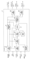
- FIG. 2 is a block diagram of an example of the functional configuration of the controller in FIG. 1.
- FIG. (a) to (c) are explanatory diagrams of an example of the parking assistance method of the first embodiment.
- (a) to (d) are schematic diagrams of examples of superimposition of target parking spaces. It is a flow chart of an example of the parking support method of a 1st embodiment.
- (a) and (b) are explanatory diagrams of an example of the parking assistance method of the second embodiment. It is a flowchart of an example of the parking assistance method of 2nd Embodiment.
- the own vehicle 1 includes a parking support device 10 that supports parking of the own vehicle 1 at a target parking position.
- the parking support device 10 supports the vehicle 1 to travel along a target travel trajectory from the current position to the target parking position.
- automatic driving that controls the own vehicle 1 to drive the own vehicle 1 along the target traveling trajectory to the target parking position (i.e., controls all or part of the own vehicle's steering angle, driving force, and braking force) , control for automatically implementing all or part of the travel of the own vehicle 1 along the target travel trajectory) may be performed.
- Parking of the own vehicle 1 may be supported by displaying the target parking position, the target travel trajectory, and the current position of the own vehicle 1 on a display device that can be viewed by the occupant (for example, the driver) of the own vehicle 1.
- the positioning device 11 measures the current position of the own vehicle 1 and its orientation (for example, in the longitudinal direction of the vehicle body).
- the positioning device 11 comprises a Global Positioning System (GNSS) receiver, such as a Global Positioning System (GPS) receiver.
- GNSS Global Positioning System
- GPS Global Positioning System
- the human machine interface (HMI) 13 is an interface device that exchanges information between the parking assist device 10 and the occupant, and includes a display device with a display screen that can be viewed by the occupant, a speaker, a buzzer, and an operator.
- the shift switch (shift SW) 14 is a switch used by the occupant of the own vehicle 1 or the parking assist device 10 to change the shift position of the own vehicle 1 .
- the external sensor 15 detects objects within a predetermined distance from the own vehicle 1.
- the external sensor 15 detects the surrounding environment of the own vehicle 1, such as the relative position of the own vehicle 1 and objects existing around the own vehicle 1, the distance between the own vehicle 1 and the object, and the direction in which the object exists.
- the external sensor 15 may include, for example, a camera that photographs the surrounding environment of the own vehicle 1. In the following description, the camera included in the external world sensor 15 will be simply referred to as a "camera”.
- the external sensor 15 may include a distance measuring device such as a laser range finder, radar, or LiDAR.
- the vehicle sensor 16 detects various information (vehicle information) about the own vehicle 1.
- the vehicle sensors 16 include, for example, a vehicle speed sensor, a wheel speed sensor, a 3-axis acceleration sensor that detects the acceleration of the host vehicle 1 in three axial directions, a steering angle sensor that detects the steering angle, and a steering sensor that detects the turning angle of the steered wheels. It may include a steering angle sensor, a gyro sensor, and a yaw rate sensor.
- the controller 17 is an electronic control unit that performs parking assistance control.
- the controller 17 includes a processor 20 and peripheral components such as a storage device 21.
- the processor 20 may be, for example, a CPU or an MPU.
- the storage device 21 may include a semiconductor storage device, a magnetic storage device, an optical storage device, or the like.
- the functions of the controller 17 are realized, for example, by the processor 20 executing a computer program stored in the storage device 21.
- the steering actuator 19a controls the steering direction and amount of steering of the steering mechanism of the own vehicle 1 according to a control signal from the controller 17.
- the accelerator actuator 19b controls the accelerator opening degree of a drive device such as an engine or a drive motor in accordance with a control signal from the controller 17.
- the brake actuator 19c operates a braking device in response to a control signal from the controller 17.
- FIG. 2A is an explanatory diagram of an example of a process for registering a target parking position, and circle plots represent learned targets.
- registration operation an operation to instruct registration of the target parking position 30.
- the registration operation may be, for example, an operation of a "parking position registration switch" provided in the HMI 13.
- the parking assist device 10 detects the surroundings of the own vehicle 1 using the external sensor 15. is detected and stored as a learned target.
- the target object may be detected from a surrounding image obtained by photographing the surroundings of the host vehicle 1 with a camera.
- edge points on the surrounding image where the brightness of adjacent pixels changes by a predetermined amount or more, such as edges and corners of targets such as road markings, road boundaries, and obstacles, or points with characteristics in shape (feature points) is detected as a target.
- Target objects around the own vehicle 1 may be detected by a distance measuring device.
- the parking assistance device 10 stores learned target data regarding learned targets in the storage device 21 .
- the learned target data includes data representing the feature amount of the learned target (hereinafter referred to as “feature amount data”), and data representing the relative positional relationship between the learned target and the target parking position (hereinafter referred to as “feature amount data”). (hereinafter referred to as “relative position data”) and coordinate data of the target parking position 30 (hereinafter referred to as "target parking position coordinate data”).
- feature amount data data representing the feature amount of the learned target
- feature amount data data representing the relative positional relationship between the learned target and the target parking position
- target parking position coordinate data coordinate data of the target parking position 30
- the relative position data for example, the relative position of the learned target with respect to the target parking position 30 may be stored.
- the parking support device 10 can acquire the position of the learned target detected when the own vehicle 1 is located at the target parking position 30 as the relative position of the learned target with respect to the target parking position 30.
- the occupant may operate the HMI 13 to input that the own vehicle 1 is located at the target parking position 30.
- the coordinates of the learned target and the target parking position 30 in a coordinate system (hereinafter referred to as "map coordinate system") having a fixed point as the reference point may be stored.
- map coordinate system coordinate data of the target parking position 30 in the map coordinate system and angle data indicating the longitudinal direction 32 of the parking space in which the vehicle is parked at the target parking position 30 are stored.
- the target parking position coordinate data the position of the own vehicle 1 in the map coordinate system and the longitudinal direction of the vehicle body when the own vehicle 1 is located at the target parking position 30 may be stored.
- FIG. 2(b) is an explanatory diagram of an example of processing when parking assistance is implemented.
- the parking assistance device 10 operates when the vehicle 1 is located near a registered target parking position 30 and an operation by an occupant instructs activation of parking assistance control for the vehicle 1 to the target parking position 30 (hereinafter referred to as "activation operation"). ) is performed, parking assistance for the host vehicle 1 is started.
- the activation operation may be, for example, an operation of a "parking assistance activation switch" provided in the HMI 13, or a shift operation for switching between forward and backward movement of the host vehicle 1 (for example, from the drive range (D range) to the reverse range). (switching operation to R range) or switching operation from R range to D range).
- the parking support device 10 extracts targets around the own vehicle 1 from a surrounding image obtained by photographing the surroundings of the own vehicle 1 with a camera.
- targets around the own vehicle 1 that are extracted when parking assistance is implemented are referred to as "surrounding targets.”
- the triangular plot represents surrounding targets.
- the parking assistance device 10 matches the learned target stored in the storage device 21 with surrounding targets, and associates the same feature points with each other. Then, based on the relative positional relationship between the surrounding targets detected when implementing parking assistance and the own vehicle 1, and the relative positional relationship between the learned targets associated with the surrounding targets and the target parking position 30. Then, the relative position of the own vehicle 1 with respect to the target parking position 30 is calculated.
- the parking support device 10 calculates the position of the target parking position 30 on a coordinate system (hereinafter referred to as "vehicle coordinate system") based on the current position of the own vehicle 1.
- vehicle coordinate system a coordinate system
- the learned targets and the coordinates of the target parking position 30 on the map coordinate system are stored in the storage device 21
- the positions of the surrounding targets detected during parking assistance and the learned targets in the map coordinate system are stored in the storage device 21.
- the coordinates of the target parking position 30 on the map coordinate system may be converted to coordinates on the vehicle coordinate system.
- the self-position of the own vehicle 1 on the map coordinate system is determined based on the positions of surrounding targets detected during parking assistance and the learned targets' positions on the map coordinate system, and the self-position of the own vehicle 1 on the map coordinate system is calculated.
- the relative position of the own vehicle 1 with respect to the target parking position 30 may be calculated from the difference in the coordinates of the target parking position 30.
- the parking assistance device 10 calculates a target traveling trajectory 34 from the current position 33 of the own vehicle 1 to the target parking position 30 based on the relative position of the own vehicle 1 with respect to the target parking position 30.
- the parking assistance device 10 performs parking assistance control for the host vehicle 1 based on the calculated target travel trajectory 34.
- the parking assistance device 10 generates an overhead view image (around view monitor image) of the surroundings of the host vehicle 1 from the captured image generated by the camera, and provides an overhead view of the target parking frame representing the parking space in which the vehicle is parked at the target parking position 30. It is superimposed on the image and displayed on the display device of the HMI 13.
- the target parking frame is an example of "a guide figure representing a range of a predetermined size surrounding the target parking position" described in the claims.
- FIG. 3 is a block diagram of an example of the functional configuration of the controller 17.
- the HMI control unit 40 detects an operation by the occupant to register the target parking position 30 and an operation to activate parking assistance control for the registered target parking position 30.
- the HMI control unit 40 outputs a map generation command to the map generation unit 45 to cause the storage device 21 to store the learned target data.
- a control start command for starting parking assistance control of the host vehicle 1 to the target parking position 30 is output to the parking assistance control section 41 .
- the image conversion unit 42 converts the captured image of the camera into an overhead image viewed from a virtual viewpoint directly above the own vehicle 1.
- the image conversion unit 42 converts the captured image into a bird's-eye view image at a predetermined interval (for example, every time the host vehicle 1 travels a predetermined distance (for example, 50 cm) or for a predetermined time (for example, 1 second)), and converts the captured bird's-eye image into a bird's-eye view image.
- a surrounding image which is an image of the surrounding area of the own vehicle 1, is generated by accumulating along the travel route of the own vehicle 1.
- the self-position calculation unit 43 calculates the self-position and attitude (for example, the longitudinal direction of the vehicle body), which is the current position of the own vehicle 1 on the map coordinate system, by odometry (for example, dead reckoning) based on the vehicle information output from the vehicle sensor 16. calculate.
- the self-position calculation unit 43 corrects the calculation results of the self-position and orientation based on the detection results of the self-position and orientation by the positioning device 11.
- the target detection unit 44 detects a target from the surrounding image output from the image conversion unit 42.
- the target detection unit 44 may detect the position of the feature point of the target and its image feature amount as the target.
- the target detection unit 44 outputs the detected feature point position and image feature amount to the map generation unit 45 and the matching unit 47 as target data.
- the self-position acquired from the self-position calculating section 43 is outputted to the map generating section 45 and the matching section 47 in synchronization with the target object detection.
- the map generation unit 45 When the map generation unit 45 receives a map generation command from the HMI control unit 40 (that is, when the registration operation of the target parking position 30 is performed), the map generation unit 45 generates learned target data and stores it in the storage device 21 as map data 46. do. For example, the map generation unit 45 receives target data and the own position of the vehicle 1 on the map coordinate system synchronized with the target data from the target detection unit 44 . The map generation unit 45 acquires coordinate data of the target parking position 30 in the map coordinate system and angle data in the longitudinal direction 32 of the parking space in which the vehicle is parked at the target parking position 30.
- the self-position calculated by the self-position calculation unit 43 is acquired as the coordinate data of the target parking position 30, and the longitudinal angle of the vehicle body is obtained as the angle data in the longitudinal direction 32.
- the map generation unit 45 generates relative position data based on the position of the feature point included in the target object data, the position information of the own vehicle 1 synchronized therewith, and the position data of the target parking position 30.
- the map generation unit 45 also acquires feature amount data from the target object data.
- the position data of the target parking position 30 and the angle data of the parking space in the longitudinal direction 32 are used as the target parking position coordinate data. Learned target data including these relative position data, feature data, and target parking position coordinate data is stored in the storage device 21 as map data 46.
- the parking assistance control section 41 When the parking assistance control section 41 receives the control start command from the HMI control section 40 (that is, when the parking assistance control activation operation is performed), it outputs a parking position calculation command to the matching section 47.
- the matching unit 47 receives the target object data output from the target object detection unit 44 as target object data of surrounding targets, and also receives the own position of the own vehicle 1 in the map coordinate system in synchronization with this.
- the matching unit 47 reads the learned target data stored in the storage device 21 as the map data 46, and based on the target parking position coordinate data, the own vehicle 1 is positioned near the registered target parking position 30. 1 is located. When the own vehicle 1 is located near the registered target parking position 30, the matching unit 47 matches the learned target stored in the map data 46 with surrounding targets to find the same feature point.
- the butt unit 47 determines the target parking position based on the relative positional relationship between the surrounding targets and the own vehicle 1 and the relative positional relationship between the learned targets associated with the surrounding targets and the target parking position 30.
- the current relative position of the own vehicle 1 with respect to the position 30 is calculated.
- the surrounding targets are expressed as (x i , y i )
- the matching unit 47 calculates the affine transformation matrix M affine1 using the following equation based on the least squares method.
- the matching unit 47 converts the position (targetx m , targety m ) of the target parking position 30 on the map coordinate system stored in the map data 46 into a position (targetx, targety) on the vehicle coordinate system based on the following equation. .
- the abutting portion 47 converts the angle targetyaw m indicating the front-rear direction 32 of the parking space of the target parking position 30 on the map coordinate system into the angle targetyaw indicating the direction on the vehicle coordinate system based on the following equation.
- the target trajectory generation unit 48 calculates a target driving trajectory from the current position of the own vehicle 1 on the vehicle coordinate system to the target parking position 30, and a target vehicle speed profile. do.
- the steering control unit 49a controls the steering actuator 19a so that the host vehicle 1 travels along the target travel trajectory.
- the vehicle speed control section 49b receives the vehicle speed control command from the parking assistance control section 41, it controls the accelerator actuator 19b and the brake actuator 19c so that the vehicle speed of the own vehicle 1 changes according to the target vehicle speed profile.
- the parking assistance control unit 41 operates the parking brake 18 and switches the shift position to the parking range (P range).
- the HMI control unit 40 receives an overhead image of the surroundings of the own vehicle 1 from the image conversion unit 42 and displays it on the display device of the HMI 13.
- the HMI control unit 40 also receives information on the coordinates (targetx, target) of the target parking position 30 and the angle targetyaw in the longitudinal direction 32 from the butting unit 47, and receives a target parking space representing the parking space in which the vehicle is parked at the target parking position 30.
- a parking frame is displayed superimposed on an overhead image.
- FIG. 4A is a schematic diagram of an example of a display area in which an overhead image is displayed on the display device of the HMI 13.
- Reference numeral 60 indicates a display screen of the display device of the HMI 13.
- the bird's-eye view image 62 is displayed within a predetermined display area 61 of the display screen 60.
- the reference point Pr at the lower left corner of the display area 61 is taken as the coordinate origin (0,0)
- the right direction and the upward direction are taken as the positive direction of the x-axis and the positive direction of the y-axis, respectively.
- the settings of the coordinate system are not limited to this example and may be changed as appropriate.
- the display area 61 is a preset area within the display screen 60.
- the numbers of pixels in the display area 61 in the x-axis direction and the y-axis direction are Wavm and Havm, respectively.
- the number of pixels in the x-axis direction and the y-axis direction of the display area 61 is set equal to the number of pixels in the x-axis direction and the y-axis direction of the bird's-eye view image 62 output from the image conversion unit 42 to the HMI control unit 40, respectively. It's okay.
- the bird's-eye view image 62 is drawn slightly smaller than the display area 61 in order to make the boundary of the bird's-eye view image 62 easier to see, but the bird's-eye view image 62 may be displayed to fill the display area 61 ( That is, the numbers of pixels in the x-axis direction and the y-axis direction of the bird's-eye view image 62 displayed in the display area 61 may be set to Wavm and Havm, respectively).
- the bird's-eye view image 62 is an image in which an icon 63 representing the host vehicle 1 is superimposed on the center of the bird's-eye view image representing the range of the longitudinal direction length DL and the vehicle width direction length DT with the current position of the host vehicle 1 as the center.
- the length DL in the longitudinal direction and the length DT in the vehicle width direction are determined so that the occupant can grasp the sense of distance from features around the own vehicle 1 (road markings such as white lines and road boundaries such as road shoulders) shown in the bird's-eye view image 62. It is set appropriately.
- the lower left corner of the bird's-eye view image 62 is designated as the display position in the display area 61 (position Pb1 in the example of FIG. 4A).
- the HMI control unit 40 calculates a position where the target parking frame 64 is displayed in a superimposed manner on the bird's-eye view image 62.
- the target parking position Pt in the coordinate system on the display screen 60 is determined based on the coordinates (targetx, target) of the target parking position 30 received from the matching unit 47 and the scale at which the bird's-eye view image 62 is displayed on the display screen 60. calculate.
- the display position and direction of the target parking frame 64 in the coordinate system on the display screen 60 are set based on the angle targetyaw received from the abutment part 47 and the target parking position Pt.
- the target parking position Pt is set to the center position of the target parking frame 64, and the direction indicated by the angle targetyaw is set to the front-rear direction of the target parking frame 64.
- the size (length in the longitudinal direction and length in the lateral direction) of the target parking frame 64 displayed on the display screen 60 may be set according to the scale of the bird's-eye view image 62 and the size of the host vehicle 1, for example.
- the size of the target parking frame 64 may be set to be approximately equal to the size of the area occupied by the host vehicle 1 in the bird's-eye view image 62.
- the size of the target parking frame 64 may be set to be slightly larger than the area occupied by the own vehicle 1 to provide a margin, or may be set to be slightly smaller than the area occupied by the own vehicle 1.
- the size of the target parking space 64 is set as the initial value. It may be set in advance as a value.
- the display position of the target parking frame 64 is set outside the range of the bird's-eye view image 62, as shown in FIG. 4(a).
- the relative position of the target parking frame 64 with respect to the icon 63 indicating the own vehicle 1 cannot be correctly grasped. Therefore, when the bird's-eye view image 62 is displayed at the first display position Pb1 of the display screen 60, if a predetermined range or more of the target parking slot 64 can be displayed within the display area 61, the HMI control unit 40 An overhead view image 62 is displayed at one display position Pb1.
- the display position for displaying the bird's-eye view image 62 is set to the first display position Pb1
- the bird's-eye view image 62 is displayed to fill the display area 61 (that is, the bird's-eye view image 62 is displayed with the number of pixels in the x-axis direction and the pixel count in the y-axis direction Wavm and Havm, respectively, and 62 is set to the reference point Pr at the lower left corner of the display area 61)
- the predetermined range of the target parking frame 64 may be referred to as a "necessary display range.”
- the bird's-eye view image 62 is displayed at the first display position Pb1 of the display screen 60, if more than a predetermined range of the target parking slot 64 cannot be displayed within the display area 61, as shown in FIG.
- the bird's-eye view image 62 is displayed at a second display position Pb2 of the display screen 60, which is different from the first display position Pb1. This makes it possible to display more than the required display range of the target parking frame 64 within the display area 61.
- a portion of the bird's-eye view image 62 that appears outside the display area 61 due to a change in the display position and a portion of the target parking frame 64 that does not fit within the display area 61 are cut out, and the remaining portion is placed within the display area 61. may be displayed.
- the HMI control unit 40 sets the offset direction (movement direction) of the display position of the bird's-eye view image 62 with respect to the reference position (i.e., the first display position Pb1) so that more than the necessary display range of the target parking frame 64 can be displayed within the display area 61.
- the offset amount (movement amount) is determined, and the second display position Pb2 is calculated by offsetting the first display position Pb1 by the offset amount in the offset direction. Refer to FIG. 4(c).
- the offset direction of the display position of the bird's-eye view image 62 is determined by the position of the target parking position Pt when the bird's-eye view image 62 is displayed to fill the display area 61.
- Region R1 is a region where the x coordinate is smaller than 0 and the y coordinate is larger than Havm
- region R2 is a region where the x coordinate is 0 or more and Wavm or less and the y coordinate is larger than Havm
- region R3 is a region whose x coordinate and y coordinate are Wavm. , Havm.
- the region R4 is a region where the x coordinate is smaller than 0 and the y coordinate is 0 or more and less than Havm
- the region R5 is a region where the x coordinate is larger than Wavm and the y coordinate is 0 or more and less than Havm.
- Region R6 is a region where the x and y coordinates are smaller than 0
- region R7 is a region where the x coordinate is 0 or more and Wavm or less and the y coordinate is smaller than 0
- region R8 is a region where the x coordinate is larger than Wavm and the y coordinate is smaller than 0. This is an area smaller than 0.
- the offset direction of the display position of the bird's-eye view image 62 may be set to the lower right direction (increase the x coordinate, decrease the y coordinate), and when the target parking position Pt is in the region R2, The offset direction of the display position of the bird's-eye view image 62 may be set downward (the y-coordinate is decreased without changing the x-coordinate), and when the target parking position Pt is in the region R3, the offset direction of the display position of the bird's-eye view image 62 may be set to the lower left direction. (The x and y coordinates may be decreased).
- the offset direction of the display position of the bird's-eye view image 62 may be set to the right (increase the x-coordinate without changing the y-coordinate), and when the target parking position Pt is in the region R5, The offset direction of the display position of the image 62 may be set to the left (the x coordinate is decreased without changing the y coordinate).
- the offset direction of the display position of the bird's-eye view image 62 may be set to the upper right direction (increasing the x and y coordinates), and when the target parking position Pt is in the area R7, the offset direction of the display position of the bird's-eye view image 62 may be set to the upper right direction (increasing the x and y coordinates).
- the offset direction of the display position may be set upward (increase the y coordinate without changing the x coordinate), and when the target parking position Pt is in area R8, the offset direction of the display position of the bird's-eye view image 62 may be set upward (the x coordinate is increased). (decrease, increase y-coordinate).
- FIG. 4B shows a bird's-eye view image so that the necessary display range of the target parking space 64 can be displayed within the display area 61, including the center of the target parking space 64 (for example, the target parking position Pt) or more.
- An example of setting the offset direction and offset amount of the display position of No. 62 is shown below.
- the x-direction offset amount ofx is set to Px based on the coordinates (-Px, -Py) of the target parking position Pt when the bird's-eye view image 62 is displayed to fill the display area 61 in FIG. 4(a).
- the y-direction offset amount ofy is set to Py.
- the required display range of the target parking space 64 is not limited to the above example, and may be set as appropriate so that the target parking space 64 displayed on the display screen 60 can be easily understood by the occupant.
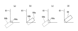
- the required display range may be a range that includes at least a portion of each of the two sides 64a and 64b of the rectangular target parking frame 64 (FIG. 5(a)), The range may include the full length of each of the two sides 64a and 64b (FIG. 5(b)), or the range may include the full length of at least one short side 64a of the rectangular target parking frame 64. (FIG. 5(c)), or the range may include all four sides of the rectangular shape (FIG. 5(d)).
- the HMI control unit 40 calculates the coordinates of the four corners of the rectangular target parking slot 64 based on the target parking position Pt and the angle targetyaw, and displays the above-mentioned required display range or more within the display area 61.
- the offset direction and offset amount of the display position of the bird's-eye view image 62 may be determined so that the display position of the bird's-eye view image 62 can be offset.
- FIG. 6 is a flowchart of an example of the parking assistance method according to the first embodiment.
- the HMI control unit 40 calculates a target parking position Pt in the coordinate system on the display screen 60. Furthermore, the display position and direction of the target parking frame 64 are calculated.
- the HMI control unit 40 determines whether a predetermined range or more of the target parking frame 64 can be displayed within the display area 61 when the bird's-eye view image 62 is displayed at the first display position Pb1. If the predetermined range or more of the target parking frame 64 cannot be displayed within the display area 61 (step S2: N), the process proceeds to step S3.
- step S2 If a predetermined range or more of the target parking frame 64 can be displayed within the display area 61 (step S2: Y), the process proceeds to step S7.
- step S3 the HMI control unit 40 calculates the offset amount (ofx, ofy) of the display position of the bird's-eye view image 62.
- step S4 the HMI control unit 40 calculates the display position of the target parking frame 64 after being offset by the offset amount (ofx, ofy).
- step S5 the HMI control unit 40 displays the bird's-eye view image 62 at the second display position Pb2, which is the display position offset by the offset amount (ofx, ofy).
- step S6 the HMI control unit 40 displays the target parking frame 64 in a superimposed manner at the display position offset (moved) by the offset amount (ofx, ofy). The process then ends.
- step S7 the HMI control unit 40 displays the bird's-eye view image 62 at the first display position Pb1.
- step S8 the HMI control unit 40 displays the target parking frame 64 in a superimposed manner at the position calculated in step S1. The process then ends.
- the range that can be displayed in the display area 61 i.e., the length DL in the longitudinal direction centered on the current position of the host vehicle 1 and The bird's-eye view image 62 can be displayed at the second display position Pb2 so as to include the entire vehicle width direction length DT).
- the HMI control unit 40 calculates the reduction rate scale using the following equation.
- the HMI control unit 40 performs affine transformation to offset the display positions of the bird's-eye view image 62 and the target parking space 64 by an x-direction offset amount ofx and a y-direction offset amount ofy, and to reduce the bird's-eye view image 62 and the target parking space 64 by a reduction rate scale.
- the matrix M affine2 is set by the following equation.
- the HMI control unit 40 transforms the coordinates of the overhead image 62 and the target parking slot 64 using an affine transformation matrix M affine2 . Specifically, if the coordinates of each pixel in the bird's-eye view image 62 before conversion and the coordinates of the boundary of the target parking frame 64 are (Px1, Py1), the coordinates of each pixel in the bird's-eye view image 62 after offset and reduction and the target parking The coordinates (Px2, Py2) of the boundary of the frame 64 are calculated using the following equation.
- the HMI control unit 40 may draw grid lines 65 in the background portion of the display area 61 (an area where the bird's-eye view image 62 is not displayed) as shown in FIG. 7(a).
- the HMI control unit 40 may display, in the display area 61, an image obtained by adding a background image 66 in which a grid is drawn to the bird's-eye view image 62, as shown in FIG. 7(b).
- FIG. 8 is a flowchart of an example of the parking assistance method according to the second embodiment.
- the processing in steps S10 and S11 is similar to the processing in steps S1 and S2 in FIG. If the predetermined range or more of the target parking frame 64 cannot be displayed within the display area 61 (step S11: N), the process proceeds to step S12. If a predetermined range or more of the target parking frame 64 can be displayed within the display area 61 (step S11: Y), the process proceeds to step S17.
- the process in step S12 is similar to step S3 in FIG.
- step S13 the HMI control unit 40 calculates the reduction rate scale.
- step S14 the HMI control unit 40 calculates the display position of the target parking frame 64 when the overhead image 62 is offset by the offset amount (ofx, ofy) and reduced by the reduction rate scale.
- step S15 the HMI control unit 40 displays the bird's-eye view image 62 offset by the offset amount (ofx, ofy) and reduced by the reduction rate scale.
- step S16 the HMI control unit 40 superimposes and displays the target parking frame 64 that is offset by the offset amount (ofx, ofy) and reduced by the reduction rate scale. The process then ends.
- the processing in steps S17 and S18 is similar to the processing in steps S7 and S8 in FIG.
- targets around the target parking position 30 stored in advance are matched with targets detected around the own vehicle 1 when parking assistance control is executed.
- the parking assistance method of the present invention is not limited to such a method of determining the target parking position.
- a target object indicating a parking lot for example, a road surface display such as a parking frame line or a three-dimensional object such as a wheel stop
- the target parking position is determined relative to the current position of the own vehicle 1. Thirty relative positions may be detected.
- the bird's-eye view image is displayed at the first display position of the display screen, and when the bird's-eye view image is displayed at the first display position of the display screen, the guide figure is displayed at the first display position of the display screen. If a predetermined range or more of the figure cannot be displayed within the display area, the overhead image is displayed at a second display position on the display screen that is different from the first display position.
- the bird's-eye view image displayed in the display area may be reduced. Thereby, it is possible to suppress a decrease in the display range of the bird's-eye view image after changing the display position of the bird's-eye view image.
- the bird's-eye view image that includes the entire range that can be displayed in the display area when the bird's-eye view image display position is set to the first display position is moved to the second display position. May be displayed. Thereby, even if the display position of the bird's-eye view image is changed, the entire range of the bird's-eye view image that could be displayed before the change can be displayed.
- the predetermined range of the guide figure may include a portion of each of at least two sides of the rectangular guide figure. Further, the predetermined range of the guide figure may include the entire length of at least two sides of the rectangular guide figure. Further, the predetermined range of the guide figure may include the entire length of at least one short side of the rectangular guide figure. Further, the predetermined range of the guide figure may include all four sides of the rectangular guide figure. Further, the predetermined range of the guide figure may include the center point of the guide figure. Thereby, the guide figure can be displayed in a manner that is easily understood by the occupant.
- the own vehicle 1 may be controlled so as to travel in the same direction. Thereby, parking of the host vehicle 1 can be supported.
Landscapes
- Engineering & Computer Science (AREA)
- Automation & Control Theory (AREA)
- Mechanical Engineering (AREA)
- Transportation (AREA)
- Human Computer Interaction (AREA)
- Traffic Control Systems (AREA)
Priority Applications (3)
| Application Number | Priority Date | Filing Date | Title |
|---|---|---|---|
| JP2024533198A JP7772220B2 (ja) | 2022-07-11 | 2022-07-11 | 駐車支援方法及び駐車支援装置 |
| PCT/JP2022/027273 WO2024013807A1 (ja) | 2022-07-11 | 2022-07-11 | 駐車支援方法及び駐車支援装置 |
| CN202280098030.3A CN119562911A (zh) | 2022-07-11 | 2022-07-11 | 停车辅助方法及停车辅助装置 |
Applications Claiming Priority (1)
| Application Number | Priority Date | Filing Date | Title |
|---|---|---|---|
| PCT/JP2022/027273 WO2024013807A1 (ja) | 2022-07-11 | 2022-07-11 | 駐車支援方法及び駐車支援装置 |
Publications (1)
| Publication Number | Publication Date |
|---|---|
| WO2024013807A1 true WO2024013807A1 (ja) | 2024-01-18 |
Family
ID=89536291
Family Applications (1)
| Application Number | Title | Priority Date | Filing Date |
|---|---|---|---|
| PCT/JP2022/027273 Ceased WO2024013807A1 (ja) | 2022-07-11 | 2022-07-11 | 駐車支援方法及び駐車支援装置 |
Country Status (3)
| Country | Link |
|---|---|
| JP (1) | JP7772220B2 (https=) |
| CN (1) | CN119562911A (https=) |
| WO (1) | WO2024013807A1 (https=) |
Citations (8)
| Publication number | Priority date | Publication date | Assignee | Title |
|---|---|---|---|---|
| JP2009101984A (ja) * | 2007-10-01 | 2009-05-14 | Nissan Motor Co Ltd | 駐車支援装置及び方法 |
| JP2009111946A (ja) * | 2007-11-01 | 2009-05-21 | Alpine Electronics Inc | 車両周囲画像提供装置 |
| JP2010184588A (ja) * | 2009-02-12 | 2010-08-26 | Clarion Co Ltd | 車両周辺監視装置 |
| JP2012071635A (ja) * | 2010-09-28 | 2012-04-12 | Aisin Seiki Co Ltd | 駐車支援装置 |
| JP2013006548A (ja) * | 2011-06-27 | 2013-01-10 | Clarion Co Ltd | 駐車支援装置 |
| WO2019008764A1 (ja) * | 2017-07-07 | 2019-01-10 | 日産自動車株式会社 | 駐車支援方法及び駐車支援装置 |
| JP2021116013A (ja) * | 2020-01-29 | 2021-08-10 | パナソニックIpマネジメント株式会社 | 車両および画像処理装置 |
| CN114693001A (zh) * | 2022-04-24 | 2022-07-01 | 中汽创智科技有限公司 | 一种泊车位预测方法、装置、电子设备及存储介质 |
-
2022
- 2022-07-11 CN CN202280098030.3A patent/CN119562911A/zh active Pending
- 2022-07-11 JP JP2024533198A patent/JP7772220B2/ja active Active
- 2022-07-11 WO PCT/JP2022/027273 patent/WO2024013807A1/ja not_active Ceased
Patent Citations (8)
| Publication number | Priority date | Publication date | Assignee | Title |
|---|---|---|---|---|
| JP2009101984A (ja) * | 2007-10-01 | 2009-05-14 | Nissan Motor Co Ltd | 駐車支援装置及び方法 |
| JP2009111946A (ja) * | 2007-11-01 | 2009-05-21 | Alpine Electronics Inc | 車両周囲画像提供装置 |
| JP2010184588A (ja) * | 2009-02-12 | 2010-08-26 | Clarion Co Ltd | 車両周辺監視装置 |
| JP2012071635A (ja) * | 2010-09-28 | 2012-04-12 | Aisin Seiki Co Ltd | 駐車支援装置 |
| JP2013006548A (ja) * | 2011-06-27 | 2013-01-10 | Clarion Co Ltd | 駐車支援装置 |
| WO2019008764A1 (ja) * | 2017-07-07 | 2019-01-10 | 日産自動車株式会社 | 駐車支援方法及び駐車支援装置 |
| JP2021116013A (ja) * | 2020-01-29 | 2021-08-10 | パナソニックIpマネジメント株式会社 | 車両および画像処理装置 |
| CN114693001A (zh) * | 2022-04-24 | 2022-07-01 | 中汽创智科技有限公司 | 一种泊车位预测方法、装置、电子设备及存储介质 |
Also Published As
| Publication number | Publication date |
|---|---|
| JP7772220B2 (ja) | 2025-11-18 |
| CN119562911A (zh) | 2025-03-04 |
| JPWO2024013807A1 (https=) | 2024-01-18 |
Similar Documents
| Publication | Publication Date | Title |
|---|---|---|
| JP2008213647A (ja) | 駐車支援方法及び駐車支援装置 | |
| JP7816484B2 (ja) | 駐車支援方法及び駐車支援装置 | |
| CN117677553B (zh) | 驻车辅助方法以及驻车辅助装置 | |
| JP7772220B2 (ja) | 駐車支援方法及び駐車支援装置 | |
| WO2024157443A1 (ja) | 駐車支援方法及び運転支援装置 | |
| CN119404238B (zh) | 驻车辅助方法以及驻车辅助装置 | |
| CN105517843B (zh) | 用于操纵车辆的方法 | |
| JP2023021775A (ja) | 駐車支援方法及び駐車支援装置 | |
| WO2025088729A1 (ja) | 駐車支援方法及び駐車支援装置 | |
| CN118339066B (zh) | 停车辅助方法及停车辅助装置 | |
| CN119301657B (zh) | 驻车辅助方法以及驻车辅助装置 | |
| WO2024157449A1 (ja) | 駐車支援方法及び駐車支援装置 | |
| EP4656479A1 (en) | Parking assistance method and parking assistance device | |
| WO2023119656A1 (ja) | 駐車支援方法及び駐車支援装置 | |
| JP7726043B2 (ja) | 駐車支援方法及び駐車支援装置 | |
| JP7831683B2 (ja) | 駐車支援方法及び駐車支援装置 | |
| WO2025088730A1 (ja) | 駐車支援方法及び駐車支援装置 | |
| EP4656478A1 (en) | Parking assistance method and parking assistance device | |
| JP2023130127A (ja) | 駐車支援方法及び駐車支援装置 | |
| WO2026028346A1 (ja) | 駐車支援方法、駐車支援装置及び駐車支援システム | |
| WO2024157441A1 (ja) | 駐車支援方法及び駐車支援装置 | |
| WO2024157444A1 (ja) | 駐車支援方法及び駐車支援装置 | |
| WO2026033704A1 (ja) | 駐車支援方法及び駐車支援装置 | |
| WO2024157442A1 (ja) | 駐車支援方法及び駐車支援装置 | |
| WO2025257900A1 (ja) | 駐車支援方法及び駐車支援装置 |
Legal Events
| Date | Code | Title | Description |
|---|---|---|---|
| 121 | Ep: the epo has been informed by wipo that ep was designated in this application |
Ref document number: 22950468 Country of ref document: EP Kind code of ref document: A1 |
|
| WWE | Wipo information: entry into national phase |
Ref document number: 2024533198 Country of ref document: JP |
|
| WWE | Wipo information: entry into national phase |
Ref document number: 202280098030.3 Country of ref document: CN |
|
| WWE | Wipo information: entry into national phase |
Ref document number: 2022950468 Country of ref document: EP |
|
| NENP | Non-entry into the national phase |
Ref country code: DE |
|
| ENP | Entry into the national phase |
Ref document number: 2022950468 Country of ref document: EP Effective date: 20250211 |
|
| WWP | Wipo information: published in national office |
Ref document number: 202280098030.3 Country of ref document: CN |
|
| WWW | Wipo information: withdrawn in national office |
Ref document number: 2022950468 Country of ref document: EP |
|
| 122 | Ep: pct application non-entry in european phase |
Ref document number: 22950468 Country of ref document: EP Kind code of ref document: A1 |