WO2024009472A1 - 論理式生成装置、論理式生成方法、プログラム - Google Patents
論理式生成装置、論理式生成方法、プログラム Download PDFInfo
- Publication number
- WO2024009472A1 WO2024009472A1 PCT/JP2022/027017 JP2022027017W WO2024009472A1 WO 2024009472 A1 WO2024009472 A1 WO 2024009472A1 JP 2022027017 W JP2022027017 W JP 2022027017W WO 2024009472 A1 WO2024009472 A1 WO 2024009472A1
- Authority
- WO
- WIPO (PCT)
- Prior art keywords
- inference
- logical
- logical formula
- information
- background knowledge
- Prior art date
- Legal status (The legal status is an assumption and is not a legal conclusion. Google has not performed a legal analysis and makes no representation as to the accuracy of the status listed.)
- Ceased
Links
Images



Classifications
-
- G—PHYSICS
- G06—COMPUTING OR CALCULATING; COUNTING
- G06N—COMPUTING ARRANGEMENTS BASED ON SPECIFIC COMPUTATIONAL MODELS
- G06N5/00—Computing arrangements using knowledge-based models
- G06N5/04—Inference or reasoning models
Definitions
- the present invention relates to a logical formula generation device, a logical formula generation method, and a program.
- Deductive reasoning is a process that receives as input information a logical formula (premise) that represents premise information and a logical formula (background knowledge) that represents inference rules. This is an inference method that outputs the derived logical formula (consequence).
- Abduction, Abductive reasoning is a logical formula (hypothesis, This is an inference method that outputs (hypothesis).
- deductive reasoning and hypothetical reasoning are theoretically different modes of logical reasoning, they are the same in that they receive input information and inference rules and output inference results, and are essentially the same when implemented on a computer. It can be interpreted as something. Therefore, models based on deductive reasoning or hypothetical reasoning are collectively called a logical inference model, and a software program that implements calculation processing using the logical inference model on a computer is called a logical inference engine.
- Non-Patent Document 1 discloses a method for implementing weighted abduction, which is one type of hypothesis inference, on a computer.
- Non-Patent Document 2 discloses a method for implementing Markov Logic Network, which is one type of deductive reasoning, on a computer.
- the above problem can be subdivided into several issues.
- the first is that the work requires a long time spent by personnel with deep knowledge of logical inference engines, resulting in large human and economic costs.
- knowledge and information are stored in logical representations, which structures are based on semantic requirements, which structures are based on computationally efficient requirements, and which are related to inferential behavior? Since it is not obvious whether the structure comes from a request or not, it is not possible to automatically rewrite the logical expression.
- the purpose of the present disclosure is to solve the above-mentioned problem that the construction and maintenance of a logical inference system requires a lot of human man-hours.
- a logical formula generation device that is one form of the present disclosure includes: Based on background knowledge information representing an inference rule, input information to be inferred by the inference rule, an inference schema representing an inference method in the inference process, and a conceptual schema representing a concept handled in the inference process, a planning means for generating background knowledge information and a logical conversion protocol for converting the input information into a logical formula; a conversion means for converting the background knowledge information and the input information into a logical formula based on the generated logical conversion protocol; Equipped with The structure is as follows.
- a logical formula generation method that is one form of the present disclosure includes: Based on background knowledge information representing an inference rule, input information to be inferred by the inference rule, an inference schema representing an inference method in the inference process, and a conceptual schema representing a concept handled in the inference process, Generating a logic conversion protocol for converting background knowledge information and the input information into a logical formula, converting the background knowledge information and the input information into a logical formula based on the generated logical conversion protocol;
- the structure is as follows.
- a program that is one form of the present disclosure is Based on background knowledge information representing an inference rule, input information to be inferred by the inference rule, an inference schema representing an inference method in the inference process, and a conceptual schema representing a concept handled in the inference process, Generating a logic conversion protocol for converting background knowledge information and the input information into a logical formula, converting the background knowledge information and the input information into a logical formula based on the generated logical conversion protocol; have a computer perform a process,
- the structure is as follows.
- the present disclosure can reduce the human labor required for constructing and maintaining a logical inference system.
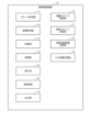
- FIG. 1 is a block diagram showing the configuration of a logical formula generation device in Embodiment 1 of the present disclosure.
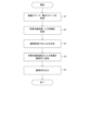
- 2 is a flowchart showing the operation of the logical formula generation device disclosed in FIG. 1.
- FIG. FIG. 2 is a block diagram showing the configuration of a logical formula generation device in Embodiment 2 of the present disclosure.
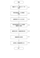
- 4 is a flowchart showing the operation of the logical formula generation device disclosed in FIG. 3.
- FIG. FIG. 3 is a block diagram showing the hardware configuration of a logical formula generation device in Embodiment 3 of the present disclosure.
- FIG. 3 is a block diagram showing the configuration of a logical formula generation device in Embodiment 3 of the present disclosure.
- FIG. 1 is a diagram for explaining the configuration of a logical formula generation device
- FIG. 2 is a diagram for explaining the processing operation of the logical formula generation device.
- the logical formula generation device 10 in this embodiment makes expectations regarding the schema that defines the inference method that is desired to be realized in the target domain, and the inference rules and input information that are written based on some description format other than logical formulas. This is a device that converts inference rules and input information into logical formulas and outputs them so as to satisfy the inference method.
- the configuration and operation of the logical formula generation device will be described below.
- the logical formula generation device 10 is composed of one or more information processing devices including an arithmetic unit and a storage device.
- the logical inference device 10 includes a schema acquisition section 11, an information acquisition section 12, a planning section 13, a conversion section 14, and an output section 15, as shown in FIG.
- the functions of the schema acquisition unit 11, information acquisition unit 12, planning unit 13, conversion unit 14, and output unit 15 are realized by the arithmetic unit executing programs stored in the storage device for realizing each function. be able to.
- the logical formula generation device 10 also includes an inference schema storage section 16, a conceptual schema storage section 17, a background knowledge information storage section 18, and an input information storage section 19.
- the inference schema storage unit 16, the conceptual schema storage unit 17, the background knowledge information storage unit 18, and the input information storage unit 19 are configured by storage devices.
- the schema acquisition unit 11 acquires an inference schema representing the definition of the inference method desired to be realized from the inference schema storage unit 16 (step S1).
- the inference schema is information that describes, in some format, the definition of the inference method that the user wants to implement.
- the definition of the inference method includes information such as "what kind of logical inference model is used” and "what kind of logical inference engine is used”. Additionally, as information regarding the contents of the inference that is desired to be realized, which is described in the inference schema, there is also the following information using "concepts" which will be described later.
- the information you want to obtain as the output of the inference method such as ⁇ I want to predict whether a particular symptom exists'' or ⁇ I want to derive the most appropriate combination of pathological conditions based on observed information.'' be.
- the format used to describe the inference schema may be some kind of text format that is assumed to be written by a human, or may be described as binary information that is assumed to be managed by a computer.
- the schema acquisition unit 11 acquires a conceptual schema representing definitions of concepts to be treated as inference rules and components of input information in an inference method to be implemented from the conceptual schema storage unit 17 (step S1).
- a conceptual schema is information that describes, in some format, definitions of concepts that the user wants to handle as components of inference rules and input information in an inference method that the user wants to implement.
- the definition of a concept includes information necessary to express the concept as a logical expression, such as the name and constituent elements of the concept. For example, "information for representing a concept as a logical formula" in a conceptual schema is mainly composed of two types of information: "components that make up the concept" and "logical characteristics of each component.” .
- the concepts include pneumonia, petition, etc.
- the following definition can be considered for the concept of "pneumonia”.
- the components that make up “pneumonia” are "affected persons,””severity," and "symptoms.”
- - Regarding the component "affected person”, the following logical characteristics hold true.
- ⁇ One “pneumonia” always has only one “affected person.”
- ⁇ Different types of pneumonia do not have the same ⁇ affected persons.'' - Regarding the component "severity”
- ⁇ “Severity” is expressed as an integer value.
- One type of “pneumonia” always has only one “severity”.
- the format used to describe the conceptual schema may be some kind of text format that is assumed to be written by a human, or may be written as binary information that is assumed to be managed by a computer.
- an existing ontology description language such as OWL (Ontology Web Language) may be used.
- the information acquisition unit 12 acquires background knowledge information expressing the inference rule in some formal language from the background knowledge information storage unit 18 (step S2).
- Background knowledge information is information that expresses, in some formal language, a set of inference rules (background knowledge) that if the antecedent holds true, the consequent holds true.
- the background technical information is information that "If you have pneumonia with severity level 3, you will develop sepsis.”
- the concept "sepsis” has only "affected persons” as a component.
- a description representing a variable such as $1 is used to represent that the different concepts "pneumonia” and “sepsis” share the same entity as the component "patient.”
- Input information is information that is subjected to inference processing using inference rules.
- any format may be used to describe the background knowledge information and input information, but a language that is based on concepts defined by a conceptual schema, that is, a language that has the expressive ability to describe such concepts. Good.
- the information acquisition unit 12 may acquire either or all of the background knowledge information and input information by reading it from a storage device built into the logical formula generation device, or may acquire it by reading it from an external storage device. Good too. Further, the information acquisition unit 12 may acquire the background knowledge information and input information by receiving any or all of the background knowledge information and input information from another device via the communication unit. Further, the information acquisition unit 12 generates either or all of background knowledge information and input information in response to a user's input operation performed via an arbitrary input device such as a mouse or a touch panel, and transmits the generated information. You may obtain it.
- the planning unit 13 refers to the inference schema, conceptual schema, background knowledge information, and input information, and generates a logical conversion protocol that is a method for converting the background knowledge information and input information into logical formulas ( Step S3).
- the logical conversion protocol is information that describes a method (conversion rule) for converting background knowledge information and input information into a logical formula in an arbitrary format.
- each schema and each An expert system may be constructed that receives information as input and outputs a logical conversion protocol.
- a logical conversion protocol may be determined and generated based on statistical analysis by mapping the structural features of each schema and each piece of information onto a vector space.
- the conversion unit 14 converts the background knowledge information and input information into a logical formula based on the logical conversion protocol generated in the planning unit 13 (step S4). That is, the conversion unit 14 converts the background knowledge information and input information into a logical formula using a logic conversion protocol that includes a conversion rule for converting the components of the background knowledge information and input information into a logical formula.
- the logical conversion protocol is basically composed of information such as "which argument of which logical formula each component of each concept corresponds to.”
- the logical conversion protocol for the above-mentioned "pneumonia" concept is generated.
- r is a reference logical variable that indicates pneumonia itself.
- p is a logical variable indicating the affected person.
- the third argument x is a logical variable representing severity. - Symptoms for a certain pneumonia r are described as different logical expressions that share the same variables.
- the output unit 15 outputs the logical formula generated by the conversion unit 14 as input information and an inference rule (step S5).
- the output unit 15 may display the logical formula on a display panel, or may store the logical formula in a recording medium (not shown). Further, the output unit 15 may output the logical formula to another device via an input/output interface or a communication interface, for example.
- the logical expression generation device automatically generates and outputs an appropriate logical expression for the input information and background knowledge information so as to realize the inference method defined by the inference schema and the conceptual schema.
- the logical expression generation device compared to manually designing and writing logical expressions of input information and background knowledge information, it is possible to improve human efficiency and reduce human man-hours involved in constructing a logical inference system, as well as to improve the human efficiency required for the work.
- the knowledge and skills required can be reduced.
- knowledge and information can be stored separately from logical expressions, and appropriate logical expressions can be automatically generated as needed.
- FIG. 3 is a diagram for explaining the configuration of the logical formula generation device
- FIG. 4 is a diagram for explaining the processing operation of the logical formula generation device. Note that here, components having the same functions as those described in Embodiment 1 will be denoted by the same reference numerals, and the description thereof will be omitted as appropriate.
- the logical formula generation device 10 in this embodiment includes an execution unit 21 and an amount conversion unit 22 in addition to the configuration of Embodiment 1.
- Each function of the execution unit 21 and the inverse conversion unit 22 can be realized by the arithmetic unit executing a program stored in a storage device for realizing each function.
- the execution unit 21 inputs the background knowledge information generated by the conversion unit 14 described above and the result of converting the input information into a logical formula, and executes the logical inference by the logical inference engine specified in the inference schema. (inference result) is obtained (step S6).
- the inference result is an execution result of a logical inference engine that receives as input the result of converting background knowledge information and input information into a logical expression, which is expressed by one or more logical expressions.
- the inverse conversion unit 22 (inverse conversion means) converts the inference result expressed by a logical formula into an expression using vocabulary on the conceptual schema based on the logical conversion protocol obtained by the above-mentioned planning unit 13 (step S7).
- the inverse conversion unit 22 utilizes the correspondence between the components of each concept and the arguments of each logical expression, which represent the conversion rules for converting the background knowledge information of the logical conversion protocol and the components of the input information into logical expressions, for the inverse conversion. Then, the inference result expressed as a logical formula is converted into an expression using the vocabulary on the conceptual schema.
- the background knowledge information expressed by a logical formula is similarly inversely transformed.
- it can be converted into an expression such as ⁇ A patient suffering from severity 3 pneumonia will develop sepsis.''
- the output unit 15 outputs the inference result expressed using the vocabulary on the conceptual schema generated by the inverse transformation unit 22 (step S8).
- the output unit 15 may display the inference result on a display panel, or may store the inference result in a recording medium (not shown).
- the output unit 18 may output the inference result to another device via an input/output interface or a communication interface, for example.
- the logical inference device automatically generates an appropriate logical expression for the input information and background knowledge information based on the inference method defined by the inference schema and the conceptual schema, and the inference result for the input information and the conceptual schema.
- FIGS. 5 and 6 are block diagrams showing the configuration of a logical formula generation device according to the third embodiment. Note that this embodiment shows an outline of the configuration of the logical formula generation device described in the above-mentioned embodiments.
- the logical formula generation device 100 is constituted by a general information processing device, and is equipped with the following hardware configuration as an example.
- ⁇ CPU Central Processing Unit
- ROM Read Only Memory
- RAM Random Access Memory
- Program group 104 loaded into RAM 103 - Storage device 105 that stores the program group 104 -
- a drive device 106 that reads and writes from and to a storage medium 110 external to the information processing device -Communication interface 107 that connects to the communication network 111 outside the information processing device ⁇ I/O interface 108 that inputs and outputs data ⁇ Bus 109 connecting each component
- the logical formula generation device 100 can construct and equip the planning means 121 and the conversion means 122 shown in FIG. 6 by having the CPU 101 acquire the program group 104 and execute it by the CPU 101.
- the program group 104 is stored in advance in the storage device 105 or ROM 102, for example, and is loaded into the RAM 103 and executed by the CPU 101 as needed.
- the program group 104 may be supplied to the CPU 101 via the communication network 111, or may be stored in the storage medium 110 in advance, and the drive device 106 may read the program and supply it to the CPU 101.
- the above-mentioned planning means 121 and conversion means 122 may be constructed of dedicated electronic circuits for realizing such means.
- FIG. 5 shows an example of the hardware configuration of the information processing device that is the logical formula generation device 100, and the hardware configuration of the information processing device is not limited to the above-mentioned case.
- the information processing device may be configured from part of the configuration described above, such as not having the drive device 106.
- the information processing device uses GPU (Graphic Processing Unit), DSP (Digital Signal Processor), MPU (Micro Processing Unit), FPU (Float) instead of the above-mentioned CPU. ing point number Processing Unit), PPU (Physics Processing Unit) , a TPU (Tensor Processing Unit), a quantum processor, a microcontroller, or a combination thereof.
- GPU Graphic Processing Unit
- DSP Digital Signal Processor
- MPU Micro Processing Unit
- FPU Float
- the planning means 121 is based on background knowledge information representing an inference rule, input information to be inferred by the inference rule, an inference schema representing an inference method in the inference process, and a concept schema representing a concept handled in the inference process. Then, a logic conversion protocol for converting background knowledge information and input information into a logical formula is generated.
- the inference schema is information such as what kind of logical inference model is based on and what kind of logical inference engine is used.
- a conceptual schema is a definition of a concept that is to be treated as a component of inference rules and input information, and includes information necessary to express the concept as a logical expression, such as the name and components of the concept. Then, the planning unit 121 generates a logical conversion protocol by applying preset conversion rules corresponding to the conditions satisfied by each schema and each piece of information.
- the conversion means 122 converts the background knowledge information and input information into a logical formula based on the generated logical conversion protocol.
- the present disclosure can reduce the human labor required for constructing and maintaining a logical inference system.
- Non-transitory computer-readable media include various types of tangible storage media.
- Examples of non-transitory computer-readable media include magnetic recording media (e.g., flexible disks, magnetic tapes, hard disk drives), magneto-optical recording media (e.g., magneto-optical disks), CD-ROMs (Read Only Memory), CD-Rs, CD-R/W, semiconductor memory (eg, mask ROM, PROM (Programmable ROM), EPROM (Erasable PROM), flash ROM, RAM (Random Access Memory)).
- the program may also be supplied to the computer via various types of transitory computer readable media. Examples of transitory computer-readable media include electrical signals, optical signals, and electromagnetic waves.
- the temporary computer-readable medium can provide the program to the computer via wired communication channels, such as electrical wires and fiber optics, or wireless communication channels.
- the present disclosure has been described above with reference to the above-described embodiments, the present disclosure is not limited to the above-described embodiments. Various changes can be made to the structure and details of the present disclosure that can be understood by those skilled in the art within the scope of the present disclosure. Further, at least one of the functions of the planning means 121 and the converting means 122 described above may be executed by an information processing device installed and connected to any location on the network, that is, a so-called cloud computer. It may also be performed by
- the logical formula generation device (Additional note 3) The logical formula generation device according to appendix 2, The planning means generates the logical conversion protocol in which the conversion rule corresponding to conditions satisfied by the background knowledge information, the input information, the inference schema, and the conceptual schema is defined.
- Logical formula generator (Additional note 4) The logical formula generation device according to supplementary note 1, The background knowledge information and the input information are described in a language set based on the concept expressed in the conceptual schema. Logical formula generator.
- (Appendix 5) The logical formula generation device according to supplementary note 1, Execution means for executing the logical formula in the inference engine based on the inference method represented by the inference schema using the inference formula as input to the inference engine; an inverse conversion means for converting an inference result of a logical expression expression obtained by executing the logical expression into an expression corresponding to the concept expressed in the conceptual schema based on the logical conversion protocol; A logical expression generator equipped with (Appendix 6) Based on background knowledge information representing an inference rule, input information to be inferred by the inference rule, an inference schema representing an inference method in the inference process, and a conceptual schema representing a concept handled in the inference process, Generating a logic conversion protocol for converting background knowledge information and the input information into a logical formula, converting the background knowledge information and the input information into a logical formula based on the generated logical conversion protocol; Logical expression generation method.
- (Appendix 7) The logical formula generation method according to appendix 6, generating the logic conversion protocol in which conversion rules for converting the background knowledge information and the components of the input information into logical expressions are defined; Logical expression generation method. (Appendix 8) The logical formula generation method according to appendix 7, generating the logical conversion protocol in which the conversion rule corresponding to conditions satisfied by the background knowledge information, the input information, the inference schema, and the conceptual schema is defined; Logical expression generation method. (Appendix 9) The logical formula generation method according to appendix 6, The background knowledge information and the input information are described in a language set based on the concept expressed in the conceptual schema. Logical expression generation method.
- Logical formula generation device 11 Schema acquisition unit 12 Information acquisition unit 13 Planning unit 14 Conversion unit 15 Output unit 16 Inference schema storage unit 17 Conceptual schema storage unit 18 Background knowledge information storage unit 19 Input information storage unit 21 Execution unit 22 Inverse conversion unit 100 Logical formula generation device 101 CPU 102 ROM 103 RAM 104 Program group 105 Storage device 106 Drive device 107 Communication interface 108 Input/output interface 109 Bus 110 Storage medium 111 Communication network 121 Planning means 122 Conversion means
Landscapes
- Engineering & Computer Science (AREA)
- Theoretical Computer Science (AREA)
- Computing Systems (AREA)
- Data Mining & Analysis (AREA)
- Evolutionary Computation (AREA)
- Physics & Mathematics (AREA)
- Computational Linguistics (AREA)
- General Engineering & Computer Science (AREA)
- General Physics & Mathematics (AREA)
- Mathematical Physics (AREA)
- Software Systems (AREA)
- Artificial Intelligence (AREA)
- Information Retrieval, Db Structures And Fs Structures Therefor (AREA)
Priority Applications (3)
| Application Number | Priority Date | Filing Date | Title |
|---|---|---|---|
| JP2024531858A JP7790572B2 (ja) | 2022-07-07 | 2022-07-07 | 論理式生成装置、論理式生成方法、プログラム |
| PCT/JP2022/027017 WO2024009472A1 (ja) | 2022-07-07 | 2022-07-07 | 論理式生成装置、論理式生成方法、プログラム |
| US18/873,355 US20250363395A1 (en) | 2022-07-07 | 2022-07-07 | Logical formula generation apparatus, logical formula generation method, and program |
Applications Claiming Priority (1)
| Application Number | Priority Date | Filing Date | Title |
|---|---|---|---|
| PCT/JP2022/027017 WO2024009472A1 (ja) | 2022-07-07 | 2022-07-07 | 論理式生成装置、論理式生成方法、プログラム |
Publications (1)
| Publication Number | Publication Date |
|---|---|
| WO2024009472A1 true WO2024009472A1 (ja) | 2024-01-11 |
Family
ID=89453103
Family Applications (1)
| Application Number | Title | Priority Date | Filing Date |
|---|---|---|---|
| PCT/JP2022/027017 Ceased WO2024009472A1 (ja) | 2022-07-07 | 2022-07-07 | 論理式生成装置、論理式生成方法、プログラム |
Country Status (3)
| Country | Link |
|---|---|
| US (1) | US20250363395A1 (https=) |
| JP (1) | JP7790572B2 (https=) |
| WO (1) | WO2024009472A1 (https=) |
Citations (3)
| Publication number | Priority date | Publication date | Assignee | Title |
|---|---|---|---|---|
| JPH05241837A (ja) * | 1992-02-28 | 1993-09-21 | Toshiba Corp | 規則集合生成装置 |
| JPH09138749A (ja) * | 1995-11-14 | 1997-05-27 | Nippon Telegr & Teleph Corp <Ntt> | 様相論理定理証明方法 |
| WO2021084733A1 (ja) * | 2019-11-01 | 2021-05-06 | 日本電気株式会社 | 情報処理装置、情報処理方法及びコンピュータ読み取り可能な記録媒体 |
-
2022
- 2022-07-07 JP JP2024531858A patent/JP7790572B2/ja active Active
- 2022-07-07 US US18/873,355 patent/US20250363395A1/en active Pending
- 2022-07-07 WO PCT/JP2022/027017 patent/WO2024009472A1/ja not_active Ceased
Patent Citations (3)
| Publication number | Priority date | Publication date | Assignee | Title |
|---|---|---|---|---|
| JPH05241837A (ja) * | 1992-02-28 | 1993-09-21 | Toshiba Corp | 規則集合生成装置 |
| JPH09138749A (ja) * | 1995-11-14 | 1997-05-27 | Nippon Telegr & Teleph Corp <Ntt> | 様相論理定理証明方法 |
| WO2021084733A1 (ja) * | 2019-11-01 | 2021-05-06 | 日本電気株式会社 | 情報処理装置、情報処理方法及びコンピュータ読み取り可能な記録媒体 |
Also Published As
| Publication number | Publication date |
|---|---|
| US20250363395A1 (en) | 2025-11-27 |
| JPWO2024009472A1 (https=) | 2024-01-11 |
| JP7790572B2 (ja) | 2025-12-23 |
Similar Documents
| Publication | Publication Date | Title |
|---|---|---|
| JP2022028908A (ja) | 多項関係生成モデルのトレーニング方法、装置、電子機器及び媒体 | |
| CN110033091B (zh) | 一种基于模型进行预测的方法和装置 | |
| US11640379B2 (en) | Metadata decomposition for graph transformation | |
| Kovalchuk et al. | A conceptual approach to complex model management with generalized modelling patterns and evolutionary identification | |
| Härer | Conceptual model interpreter for large language models | |
| Nan et al. | Stochastic configuration networks with improved supervisory mechanism | |
| JP7790572B2 (ja) | 論理式生成装置、論理式生成方法、プログラム | |
| Huang et al. | Bidirectional broad learning system | |
| JP6908101B2 (ja) | モデル生成システム、モデル生成方法およびモデル生成プログラム | |
| WO2019156131A1 (ja) | 情報処理装置、情報処理方法及びコンピュータ読み取り可能な記録媒体 | |
| Bhattacharjya et al. | An Exploratory Study on Chatbots | |
| Bobek et al. | Framework for benchmarking rule-based inference engines | |
| JP7485036B2 (ja) | 推論装置、推論方法、及びプログラム | |
| Jafarpour et al. | Exploiting OWL reasoning services to execute ontologically-modeled clinical practice guidelines | |
| JP7810262B2 (ja) | 論理推論装置、論理推論方法、プログラム | |
| Sun et al. | A Preliminary Study on the Application of Large Language Models in Power System Simulations | |
| CN119324011B (zh) | 分子生成方法、装置、电子设备及存储介质 | |
| Mascardi et al. | Semantic Web and Declarative Agent Languages and Technologies: Current and Future Trends: (Position Paper) | |
| Tian et al. | Leveraging knowledge-based reasoning towards generation of creative ideas | |
| Cao et al. | KERE: A General Reasoning Engine for Complex Problem Solving | |
| Hoshi | Merging DEL and ETL | |
| Beltiukov et al. | Deductive ergatic design of constructive tasks solutions | |
| Joshi | Prompt Engineering without Premium Tools: Evaluating ChatGPT's Free Version for Quality and Efficiency | |
| Lebedev et al. | Applicative-Frame Model of Medical Knowledge Representation | |
| Zhao et al. | Quality Defect Diagnosis Method for Prefabricated Steel Structure Residences Based on Artificial General Intelligence |
Legal Events
| Date | Code | Title | Description |
|---|---|---|---|
| 121 | Ep: the epo has been informed by wipo that ep was designated in this application |
Ref document number: 22950266 Country of ref document: EP Kind code of ref document: A1 |
|
| WWE | Wipo information: entry into national phase |
Ref document number: 18873355 Country of ref document: US |
|
| WWE | Wipo information: entry into national phase |
Ref document number: 2024531858 Country of ref document: JP |
|
| NENP | Non-entry into the national phase |
Ref country code: DE |
|
| 122 | Ep: pct application non-entry in european phase |
Ref document number: 22950266 Country of ref document: EP Kind code of ref document: A1 |
|
| WWP | Wipo information: published in national office |
Ref document number: 18873355 Country of ref document: US |