WO2024004446A1 - 音声信号再生装置、音声信号再生装置の制御方法、および音声信号再生装置の制御プログラム - Google Patents
音声信号再生装置、音声信号再生装置の制御方法、および音声信号再生装置の制御プログラム Download PDFInfo
- Publication number
- WO2024004446A1 WO2024004446A1 PCT/JP2023/019163 JP2023019163W WO2024004446A1 WO 2024004446 A1 WO2024004446 A1 WO 2024004446A1 JP 2023019163 W JP2023019163 W JP 2023019163W WO 2024004446 A1 WO2024004446 A1 WO 2024004446A1
- Authority
- WO
- WIPO (PCT)
- Prior art keywords
- audio signal
- vibration
- attached
- processor
- information
- Prior art date
- Legal status (The legal status is an assumption and is not a legal conclusion. Google has not performed a legal analysis and makes no representation as to the accuracy of the status listed.)
- Ceased
Links
Images


Classifications
-
- H—ELECTRICITY
- H04—ELECTRIC COMMUNICATION TECHNIQUE
- H04R—LOUDSPEAKERS, MICROPHONES, GRAMOPHONE PICK-UPS OR LIKE ACOUSTIC ELECTROMECHANICAL TRANSDUCERS; ELECTRIC HEARING AIDS; PUBLIC ADDRESS SYSTEMS
- H04R7/00—Diaphragms for electromechanical transducers; Cones
- H04R7/02—Diaphragms for electromechanical transducers; Cones characterised by the construction
- H04R7/04—Plane diaphragms
-
- G—PHYSICS
- G06—COMPUTING OR CALCULATING; COUNTING
- G06F—ELECTRIC DIGITAL DATA PROCESSING
- G06F3/00—Input arrangements for transferring data to be processed into a form capable of being handled by the computer; Output arrangements for transferring data from processing unit to output unit, e.g. interface arrangements
- G06F3/01—Input arrangements or combined input and output arrangements for interaction between user and computer
- G06F3/017—Gesture based interaction, e.g. based on a set of recognized hand gestures
-
- G—PHYSICS
- G06—COMPUTING OR CALCULATING; COUNTING
- G06F—ELECTRIC DIGITAL DATA PROCESSING
- G06F3/00—Input arrangements for transferring data to be processed into a form capable of being handled by the computer; Output arrangements for transferring data from processing unit to output unit, e.g. interface arrangements
- G06F3/01—Input arrangements or combined input and output arrangements for interaction between user and computer
- G06F3/048—Interaction techniques based on graphical user interfaces [GUI]
- G06F3/0487—Interaction techniques based on graphical user interfaces [GUI] using specific features provided by the input device, e.g. functions controlled by the rotation of a mouse with dual sensing arrangements, or of the nature of the input device, e.g. tap gestures based on pressure sensed by a digitiser
- G06F3/0488—Interaction techniques based on graphical user interfaces [GUI] using specific features provided by the input device, e.g. functions controlled by the rotation of a mouse with dual sensing arrangements, or of the nature of the input device, e.g. tap gestures based on pressure sensed by a digitiser using a touch-screen or digitiser, e.g. input of commands through traced gestures
- G06F3/04883—Interaction techniques based on graphical user interfaces [GUI] using specific features provided by the input device, e.g. functions controlled by the rotation of a mouse with dual sensing arrangements, or of the nature of the input device, e.g. tap gestures based on pressure sensed by a digitiser using a touch-screen or digitiser, e.g. input of commands through traced gestures for inputting data by handwriting, e.g. gesture or text
-
- G—PHYSICS
- G11—INFORMATION STORAGE
- G11B—INFORMATION STORAGE BASED ON RELATIVE MOVEMENT BETWEEN RECORD CARRIER AND TRANSDUCER
- G11B27/00—Editing; Indexing; Addressing; Timing or synchronising; Monitoring; Measuring tape travel
- G11B27/005—Reproducing at a different information rate from the information rate of recording
-
- G—PHYSICS
- G11—INFORMATION STORAGE
- G11B—INFORMATION STORAGE BASED ON RELATIVE MOVEMENT BETWEEN RECORD CARRIER AND TRANSDUCER
- G11B27/00—Editing; Indexing; Addressing; Timing or synchronising; Monitoring; Measuring tape travel
- G11B27/10—Indexing; Addressing; Timing or synchronising; Measuring tape travel
- G11B27/34—Indicating arrangements
-
- G—PHYSICS
- G06—COMPUTING OR CALCULATING; COUNTING
- G06F—ELECTRIC DIGITAL DATA PROCESSING
- G06F2200/00—Indexing scheme relating to G06F1/04 - G06F1/32
- G06F2200/16—Indexing scheme relating to G06F1/16 - G06F1/18
- G06F2200/163—Indexing scheme relating to constructional details of the computer
- G06F2200/1636—Sensing arrangement for detection of a tap gesture on the housing
-
- H—ELECTRICITY
- H04—ELECTRIC COMMUNICATION TECHNIQUE
- H04R—LOUDSPEAKERS, MICROPHONES, GRAMOPHONE PICK-UPS OR LIKE ACOUSTIC ELECTROMECHANICAL TRANSDUCERS; ELECTRIC HEARING AIDS; PUBLIC ADDRESS SYSTEMS
- H04R1/00—Details of transducers, loudspeakers or microphones
- H04R1/02—Casings; Cabinets ; Supports therefor; Mountings therein
- H04R1/028—Casings; Cabinets ; Supports therefor; Mountings therein associated with devices performing functions other than acoustics, e.g. electric candles
Definitions
- the present disclosure relates to an audio signal reproducing device, a method of controlling the audio signal reproducing device, and a control program for the audio signal reproducing device.
- Patent Document 1 describes a technology in which a speaker unit that forcibly vibrates the mirror and generates sound from the mirror is attached to a bathroom mirror. Patent Document 1 also describes a technique in which a touch sensor is provided on the surface of a mirror in order to control the speaker unit.
- the present disclosure provides an audio signal reproducing device, a method for controlling the audio signal reproducing device, and a control program for the audio signal reproducing device, which can control audio reproduction.
- the audio signal reproducing device includes a vibration generator attached to one or more attached members, the attached member to which the vibration generator is attached, or the attached member to which the vibration generator is attached.
- a vibration sensor attached to a separate attached member; a drive device that drives the vibration generator based on an audio signal to generate sound via the attached member; a processor that executes a program; a storage device that stores a program to be executed, and by causing the processor to execute the program, a user generates a vibration on the attached member to which the vibration sensor is attached based on a signal acquired from the vibration sensor.
- Position information indicating the position of vibration is generated, and control information is transmitted based on the position information.
- FIG. 1 is a diagram showing a device configuration and a functional configuration of an audio signal reproducing device according to Embodiment 1.
- FIG. 7 is a diagram illustrating a first example of a user's operation on a third attached member in the first embodiment.
- FIG. 3 is a diagram showing detection results of vibrations generated by user operations in the first embodiment.
- 7 is a diagram illustrating a second example of a user's operation on the third attached member in the first embodiment.
- FIG. 7 is a diagram illustrating a third example of a user's operation on a third attached member in the first embodiment.
- FIG. 3 is a diagram illustrating a first example of relational information in the first embodiment;
- FIG. 1 is a diagram showing a device configuration and a functional configuration of an audio signal reproducing device according to Embodiment 1.
- FIG. 7 is a diagram illustrating a first example of a user's operation on a third attached member in the first embodiment.
- FIG. 3 is a diagram showing detection results of
- FIG. 3 is a diagram showing the device configuration and functional configuration of an audio signal reproducing device according to a second embodiment.
- FIG. 7 is a diagram showing the flow of audio signal reduction processing in Embodiment 2.
- FIG. 7 is a diagram showing detection results of vibrations generated by user operations in Embodiment 2.
- FIG. 7 is a diagram showing a device configuration and a functional configuration of an audio signal reproducing device according to a third embodiment.
- 12 is a diagram showing a fourth example of a user's operation on a third attached member in the third embodiment.
- FIG. 12 is a diagram showing example 5 of a user's operation on a third attached member in Embodiment 3.
- FIG. 7 is a diagram showing example 6 of a user's operation on a third attached member in Embodiment 3;
- FIG. 7 is a diagram showing a second example of relational information in the third embodiment.
- FIG. 7 is a diagram showing a device configuration and a functional configuration of an audio signal reproducing device according to a fourth embodiment. It is a figure which shows the example 3 of relationship information.
- FIG. 7 is a diagram showing example 4 of related information.
- FIG. 7 is a diagram showing example 7 of a user's operation on a member to be attached.
- drawings are schematic diagrams with emphasis, omission, or ratio adjustment as appropriate for explaining the present disclosure, and the actual shapes, positional relationships, and ratios differ.
- the X-axis, Y-axis, and Z-axis that may be shown in the drawings indicate orthogonal coordinates arbitrarily set for the purpose of explaining the drawings.
- the Z-axis is not necessarily an axis along the vertical direction, and the X-axis and Y-axis are not necessarily in a horizontal plane.
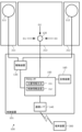
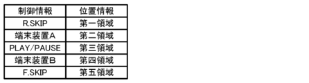
- FIG. 1 is a diagram showing the device configuration and functional configuration of an audio signal reproducing device 100 according to the first embodiment.
- the audio signal reproducing device 100 acquires an audio signal from a terminal device 300, which is an external device of the audio signal reproducing device 100, and vibrates an attached member, which is one of the attached members, based on the acquired audio signal, thereby generating an audio signal.
- This is a device that plays back .
- the audio signal reproducing device 100 includes a first vibration generator 111 and a second vibration generator 112 that are vibration generators, a first vibration sensor 121 that is a vibration sensor, and a second vibration sensor 122, a drive device 130, a communication interface 140, a processor 150, and a storage device 160.
- the drive device 130, the communication interface 140, the processor 150, and the storage device 160 are realized on one chip using so-called SoC (System on a Chip) technology, and constitute the control device 101.
- SoC System on a Chip
- a vibration generator is an actuator that vibrates an attached member to generate sound from the attached member.
- the audio signal reproducing device 100 includes a first vibration generator 111 and a second vibration generator 112, each of which is independently driven as a vibration generator to support stereo reproduction.
- the types of vibration generators are not particularly limited, and include those that drive a voice coil to generate vibrations corresponding to audio signals, and those that drive piezoelectric elements to generate vibrations that correspond to audio signals.
- a vibration generator may be referred to as an audio exciter, audio actuator, vibration speaker, or the like.
- the member to which the vibration generator is attached is not particularly limited, but a relatively hard plate-like member is suitable. Specifically, furniture, building materials, vehicle parts, etc. can be exemplified.
- the attached member is the first attached member 211 of the three mirrors arranged side by side in the left-right direction on the washstand, the mirror arranged at one end is the first attached member 211, and the mirror arranged at the other end is The arranged mirror functions as the second attached member 212.
- the first vibration generator 111 is attached to the back side of the first attached member 211 and generates sound via the first attached member 211.
- the second vibration generator 112 is attached to the back side of the second attached member 212 and generates sound via the second attached member 212.
- the first attached member 211 and the second attached member 212 are each attached to a washbasin body (not shown) via a hinge (not shown).
- the vibration of the first attached member 211 generated by the first vibration generator 111 hardly reaches the second attached member 212, and the vibration of the second attached member 212 generated by the second vibration generator 112 hardly reaches the first attached member 211.
- a vibration sensor is a sensor that detects vibrations of an attached member.
- the audio signal reproducing device 100 uses omnidirectional sensors that independently detect vibrations in order to detect the approximate position where the user knocks on the attached member to which the vibration sensor is attached. It includes a first vibration sensor 121 and a non-directional second vibration sensor 122. A specific detection method will be described later.
- the type of vibration sensor is not particularly limited, and examples include acceleration sensors using strain gauges.
- the processor 150 generates position information based on the difference in arrival time of vibrations generated by user operations, so the length of the signal line from the first vibration sensor 121 to the processor 150, Preferably, the length of the signal line from the second vibration sensor 122 to the processor 150 is substantially the same. This makes it possible to generate position information with high accuracy.
- the attachment target member to which the vibration sensor is attached is not particularly limited, but a relatively hard plate-like member through which vibrations can easily propagate is suitable, similar to the attachment target member to which the vibration generator is attached. .
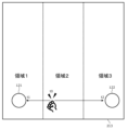
- the mirror arranged in the center functions as the third member to be mounted 213.
- the first vibration sensor 121 and the second vibration sensor 122 are respectively attached to the lower sides of both ends in the left and right direction on the back side of the third attached member 213, and detect vibrations generated in the third attached member 213, respectively.
- the third attached member 213 is attached to the washbasin body (not shown) via a hinge (not shown). The vibrations generated by the first vibration generator 111 and the second vibration generator 112 hardly reach the third attached member 213.
- the drive device 130 drives the vibration generator and outputs an audio signal that vibrates the attached member and generates sound.
- the drive device 130 amplifies and outputs the two-channel audio signal decoded by the processor 150 so as to correspond to each of the first vibration generator 111 and the second vibration generator 112.
- the communication interface 140 transmits and receives signals to and from the terminal device 300 through at least one of wireless communication and wired communication.
- the communication interface 140 conforms to the Bluetooth (registered trademark) communication standard, and performs P2P (Peer-to-Peer) communication with the terminal device 300 that has been paired in advance. : peer-to-peer) communication.
- the communication interface 140 receives, for example, an audio signal from the terminal device 300 and transmits control information to the terminal device 300.
- the processor 150 is a processing device that performs calculations and conversion of data, executes programs, controls other devices, and the like. In the case of this embodiment, processor 150 executes a program stored in storage device 160, and executes the processing described below.
- the first vibration sensor 121 and the second vibration sensor 122 detect vibrations generated when the user performs an operation such as knocking, tapping, or hitting the third attached member 213 and outputs a signal. Based on these signals, the processor 150 generates position information indicating the position operated by the user on the third attached member 213. Specifically, the processor 150 generates position information based on at least one of a difference in amplitude information, a difference in time information, and a difference in transient information obtained from the first vibration sensor 121 and the second vibration sensor 122. is generated. At this stage, the processor 150 is functioning as the position information generating section 151 by executing the program.
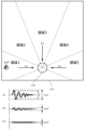
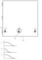
- FIG. 2 is a diagram showing an example 1 of a user's operation on the third attached member 213.
- FIG. 3 is a diagram showing the detection results of vibrations generated by user operations.
- FIG. 4 is a diagram illustrating a second example of a user's operation on the third attached member 213.
- FIG. 5 is a diagram showing a third example of the user's operation on the third attached member 213.
- the processor 150 receives an audio signal from the terminal device 300 via the communication interface 140, and the driving device 130 drives the first vibration generator 111 and the second vibration generator 112 based on the received audio signal. It is assumed that audio is being reproduced from the first attached member 211 and the second attached member 212. In this state, when the user knocks (hits or taps) the surface of the third attached member 213 once as shown in FIG. 2, the first vibration sensor 121 detects the signal shown in the upper part of FIG. The second vibration sensor 122 detects the signal shown in the lower part of FIG. The processor 150 acquires signals detected from the first vibration sensor 121 and the second vibration sensor 122, respectively.
- the processor 150 cannot obtain the time t0 of the knock, but the time t1 when the first vibration sensor 121 detects the vibration, and the second vibration sensor 122 can obtain the time t2 when the vibration was detected.
- T becomes zero.
- time t2 becomes larger than time t1
- T becomes negative according to equation (1).
- the time is equal to or greater than a first time threshold (negative value) predetermined for separating region 1 and region 2.
- time t2 becomes smaller than time t1, and T becomes positive according to equation (1). However, it is less than a second time threshold (positive value) predetermined for separating region 2 and region 3.
- the first time threshold and the second time threshold are stored in the storage device 160, and are called by the processor 150 when generating position information.
- time t2 becomes larger than time t1, and according to equation (1), T becomes a negative value that is less than or equal to the first time threshold.
- time t2 becomes smaller than time t1, and according to equation (1), T becomes a positive value equal to or greater than the second time threshold.
- the processor 150 determines that the knocked position is region 1 (see FIG. 2) when T is less than the first time threshold, and determines that the knocked position is region 1 (see FIG. 2) when T is greater than or equal to the first time threshold and less than the second time threshold. is region 2, and if T is greater than or equal to the second time threshold, position information is generated that indicates that the knocked position is region 3. Note that the first time threshold value ⁇ 0 ⁇ the second time threshold value.
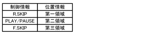
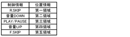
- FIG. 6 is a diagram showing example 1 of relational information.
- processor 150 transmits control information to terminal device 300 via communication interface 140 based on the generated position information.
- the storage device 160 stores relationship information that is a table showing the relationship between position information and control information, as shown in FIG.
- the position information is information generated previously, and the control information is information sent to the terminal device 300.
- the processor 150 generates position information indicating the second area by the user knocking at a midpoint between the first vibration sensor 121 and the second vibration sensor 122
- the processor 150 generates position information indicating the second area based on the relationship information.
- PLAY/PAUSE is transmitted as control information to the terminal device 300 via the communication interface 140.
- the processor 150 is functioning as the control information transmitter 152.
- the terminal device 300 that has acquired the control information executes an operation corresponding to the control information. For example, assume that the audio signal reproducing device 100 outputs PLAY/PAUSE as control information.
- the terminal device 300 that has acquired the control information starts playing the music content if it is not playing the music content (pauses it), and temporarily stops playing the music content if it is playing the music content. Stop.
- an audio signal is reproduced for the user by the vibration generator attached to the back side of the mirror provided in the washstand.
- two vibration sensors attached to the back of the mirror placed in the center perform different controls on the terminal device 300 that is outputting the audio signal. becomes possible.
- the processor 150 transmits control information to the terminal device 300, which is an external device, and the processor 150, which receives the audio signal generated based on the control information received by the terminal device 300, controls the drive device and
- the sound signal reproducing device 100 can generate sound by driving the vibration generator 111 and the second vibration generator 112, and the audio signal reproducing device 100 can reproduce the sound without impairing the design of the washbasin, and can control the terminal device. It becomes possible to accept.
- Embodiment 2 Next, embodiments of an audio signal reproducing device, a method of controlling the audio signal reproducing device, and a control program for the audio signal reproducing device will be described. Note that parts (portions) having the same functions, functions, shapes, mechanisms, and structures as those of the first embodiment are designated by the same reference numerals, and the description thereof may be omitted. Further, in the following, points different from Embodiment 1 will be mainly explained, and explanations of the same contents may be omitted.
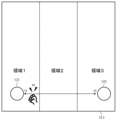
- FIG. 7 is a diagram showing the device configuration and functional configuration of the audio signal reproducing device 100 according to the second embodiment.
- the first vibration generator 111, the second vibration generator 112, the first vibration sensor 121, and the second vibration sensor 122 are attached to one attached member 210.
- the type of attached member 210 is not particularly limited. For example, a large mirror attached to the wall of a washroom, a wall of a bath (such as a unit bath), a ceiling of a bath, a door of a bath, a table, a desk, etc. can be exemplified.
- the processor 150 reduces the audio signal component from the signal acquired from the vibration sensor before generating position information. That is, the processor 150 functions as the audio signal reduction unit 153 by executing the program. This is because the vibration generator and the vibration sensor are attached to one attached member 210, so the vibration sensor detects the vibration of the attached member 210 caused by the vibration generator, and the user knocks on the attached member 210. This is because there is a possibility that the actual vibrations will be buried in the vibrations based on the audio signal.
- FIG. 8 is a diagram showing the flow of audio signal reduction processing.
- the processor 150 acquires audio signals for driving the first vibration generator 111 and the second vibration generator 112, respectively, by the driving device 130, and acquires inverse audio signals with opposite phases in almost real time. Generates signals. Furthermore, the processor 150 adjusts the amplitude of the generated reverse audio signal to match the amplitude of the vibration based on the audio signal detected by the first vibration sensor 121 and the second vibration sensor 122. The processor 150 causes the reverse audio signal to act on the reverse audio signal whose amplitude has been adjusted and the detection signals detected by the first vibration sensor 121 and the second vibration sensor 122, respectively, to extract the components of the audio signal from the detection signal. Make a reduction.
- the audio signal on which the reverse audio signal is generated is not only obtained from the output of the driving device 130 but also a decoded audio signal input to the driving device 130 or an audio signal acquired from the terminal device 300. It doesn't matter if it's a signal.
- FIG. 9 is a diagram showing the detection results of vibrations generated by user operations.
- the maximum amplitude w2 becomes larger than the maximum amplitude w1, and W becomes positive according to equation (2). However, it is less than a second amplitude threshold (a positive value) predetermined for separating region 2 and region 3.
- a second amplitude threshold (a positive value) predetermined for separating region 2 and region 3. Note that the first amplitude threshold and the second amplitude threshold are stored in the storage device 160, and are called by the processor 150 when generating position information.
- the processor 150 determines that the knocked position is region 1 (see FIG. 2) when W is less than the first amplitude threshold, and determines that the knocked position is region 1 (see FIG. 2) when W is greater than or equal to the first amplitude threshold and less than the second amplitude threshold. is in region 2, and when W is greater than or equal to the second amplitude threshold, position information is generated that indicates that the knocked position is in region 3. Note that the first amplitude threshold value ⁇ 0 ⁇ the second amplitude threshold value.
- the next transmission of control information by processor 150 is the same as in the first embodiment.
- the same effects as the audio signal reproducing device 100 according to the first embodiment can be achieved. Furthermore, even when the vibration generator and the vibration sensor are attached to the same mounted member 210 and the vibration sensor detects vibrations based on audio signals, the vibration caused by the user's knock can be correctly extracted and position information can be generated correctly. It becomes possible to do so.
- Embodiment 3 Next, embodiments of an audio signal reproducing device, a method of controlling the audio signal reproducing device, and a control program for the audio signal reproducing device will be described. Note that parts (portions) having the same functions, functions, shapes, mechanisms, and structures as those in Embodiments 1 and 2 are designated by the same reference numerals, and the description thereof may be omitted. In addition, the following description will focus on the points that are different from Embodiments 1 and 2, and the description of the same contents may be omitted.
- FIG. 10 is a diagram showing the device configuration and functional configuration of the audio signal reproducing device 100 according to the third embodiment.
- one vibration sensor 120 is attached to the third attached member 213.
- the vibration sensor 120 has a plurality of directivities (in the case of this embodiment, three directions D1, D2, and D3) that strongly detect signals arriving from the directions indicated by arrows in FIG.
- the vibration sensor 120 with directivity is a vibration sensor 120 having a characteristic that the detection sensitivity is high for vibrations coming from a specific direction, and the detection sensitivity decreases when the vibrations deviate from the specific direction.
- the processor 150 generates position information based on amplitude information indicating the strength of vibration obtained from the vibration sensor 120 with directivity in three directions.
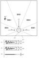
- FIG. 11 is a diagram showing example 4 of the user's operation on the third attached member 213.
- FIG. 12 is a diagram showing example 5 of the user's operation on the third attached member 213.
- FIG. 13 is a diagram showing example 6 of the user's operation on the third attached member 213.
- the method by which processor 150 generates position information based on the signal acquired from vibration sensor 120 is not particularly limited. In the case of this embodiment, when the user knocks in area 1, processor 150 obtains a signal from direction D1, a signal from direction D2, and a signal from direction D3, as shown in the graph of FIG. . The processor 150 derives the maximum amplitudes wd1, wd2, wd3 of the three acquired signals.
- the processor 150 If the maximum amplitudes wd1, wd2, and wd3 are greater than or equal to a predetermined first pointing threshold Th1 (wd1), the processor 150 generates position information indicating that area 1 has been knocked. The judgment made by the processor 150 is the same when knocking on area 3 and when knocking on area 5 shown in FIG. 13 (not shown).
- the processor 150 When the user knocks in area 2, the processor 150 obtains a signal from direction D1, a signal from direction D2, and a signal from direction D3, as shown in the graph of FIG. The processor 150 derives the maximum amplitudes wd1, wd2, wd3 of the three acquired signals. If there are no maximum amplitudes wd1, wd2, and wd3 that are equal to or higher than a predetermined first orientation threshold Th1, and there are two maximum amplitudes that are equal to or higher than a second orientation threshold th2 (wd1, wd2), the processor 150 selects the region 2 Generates location information indicating that the person has knocked. This judgment by the processor 150 is the same when knocking in area 4 (not shown).
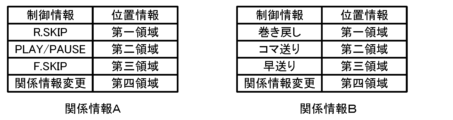
- FIG. 14 is a diagram showing example 2 of relational information.
- Processor 150 transmits control information to terminal device 300 via communication interface 140 based on the generated position information.
- the storage device 160 stores relationship information that is a table showing the relationship between position information and control information, as shown in FIG. For example, when the processor 150 generates position information indicating the second area by the user knocking on the upper left diagonal (area 2) of the vibration sensor 120, the processor 150 generates the volume control information as control information based on the related information. DOWN is sent to drive device 130 without going through communication interface 140.
- the drive device 130 that has acquired the volume DOWN signal lowers the amplification factor of the audio signal compared to the current level.
- the same effects as the audio signal reproducing device 100 according to the first embodiment can be achieved. Further, by using a vibration sensor with directivity, it becomes possible to output a lot of different control information even with one vibration sensor.
- Embodiment 4 Next, embodiments of an audio signal reproducing device, a method of controlling the audio signal reproducing device, and a control program for the audio signal reproducing device will be described. Note that parts (portions) having the same functions, functions, shapes, mechanisms, and structures as those in Embodiments 1, 2, and 3 will be denoted by the same reference numerals, and the description thereof may be omitted. In addition, the following description will focus on the points that are different from Embodiments 1, 2, and 3, and the description of the same contents may be omitted.
- FIG. 15 is a diagram showing the device configuration and functional configuration of the audio signal reproducing device 100 according to the fourth embodiment.
- the first vibration generator 111 is attached to the first attached member 211
- the second vibration generator 112 is attached to the second attached member 212
- the first vibration sensor 121 and the second vibration sensor 122 are respectively attached to the third attached member 213.
- a motion detection sensor 123 that detects the motion of the third attached member 213 is attached to the third attached member 213 to which the first vibration sensor 121 and the second vibration sensor 122 are attached.
- the motion detection sensor 123 detects the motion of the attached member to which the vibration sensor is attached.
- the type of motion detection sensor 123 is not particularly limited.
- the motion detection sensor 123 may be a sensor that detects whether the mirror is in an open or closed state.
- the motion detection sensor 123 includes a microswitch that detects the closed position of the mirror, an illuminance sensor that detects the difference in brightness on the back side of the mirror when the mirror is opened and closed, and a washbasin that maintains the mirror in the closed state.
- An example of this is a magnetic sensor that detects whether or not the object is close to a magnet attached to the object.
- a vibration sensor for movement detection may be provided in addition to the vibration sensor for detecting a knock by the user.
- at least one of the vibration sensors for knock detection may function as the motion detection sensor 123.
- the processor 150 processes the signal from the vibration sensor when the attached member moves based on the signal acquired from the motion detection sensor 123. Specifically, the processor 150 performs a process of not accepting signals from the first vibration sensor 121 and the second vibration sensor 122 while detecting that the third attached member 213 is in the open state. Let's do it. Therefore, processor 150 does not generate location information or send control information.
- the same effects as the audio signal reproducing device 100 according to the first embodiment can be achieved.
- the motion detection sensor 123 prevents malfunction by not accepting signals from the vibration sensor even if an event similar to a knock by the user occurs in an unstable state where the third attached member 213 is not closed. It becomes possible to do so.
- the present disclosure is not limited to the above embodiments.
- other embodiments of the present disclosure may be implemented by arbitrarily combining the components described in this specification or by excluding some of the components.
- the present disclosure also includes modifications obtained by making various modifications to the above-described embodiments that a person skilled in the art can think of without departing from the gist of the present disclosure, that is, the meaning indicated by the words described in the claims. It will be done.
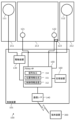
- the processor 150 controls the communication interface 140 based on the position information to perform wireless communication. You may also switch the terminal device 300 that is used. Specifically, as in Example 3 of relational information shown in FIG. 16, the paired terminal devices A and B are associated with predetermined position information as control information.
- the communication interface 140 is in a state where it can be connected to the terminal device A. In this state, when the user knocks on area 4 of the attached member to which the vibration sensor is attached, the processor 150 generates position information for the fourth area and connects the terminal device B corresponding to the fourth area. You may change the settings of the communication interface 140 so that it is possible.
- the storage device 160 may include a plurality of different types of relationship information, and the processor 150 may change the relationship information based on the generated position information. For example, as shown in FIG. 17, the storage device 160 stores relationship information A and relationship information B. The processor 150 transmits control information based on the relationship information A. When the user knocks on the fourth area, the processor 150 reads the related information B from the storage device 160 and changes the related information A to the related information B. As a result, it is possible to transmit more types of control information than can identify the position of the user's knock, and it becomes possible to perform many types of control.
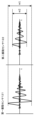
- Position information may be generated using transient information indicating transient characteristics.
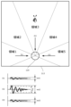
- the transient information is, for example, information indicating a decreasing tendency of amplitude. Specifically, as shown in FIG. 18, when the attached member 210 is a plate-shaped member attached via a hinge 219, the amplitude tends to decrease when the user knocks at position A near the hinge 219.
- the processor 150 generates the position information based on the fact that the decreasing tendency of the amplitude when knocking at the position C that is farthest from the hinge is different from the decreasing tendency of the amplitude when knocking at the position B that is directly above the vibration sensor 120. You may go.
- the processor 150 may generate position information by combining these pieces of information. do not have.
- a filter circuit that filters the signal detected by the vibration sensor may be interposed between the vibration sensor and the processor 150, or the processor 150 may perform the filtering.
- the filter include a high-pass filter, a low-pass filter, and a band-pass filter.
- an element capable of filtering such as a DSP (Digital Signal Processor), may be placed in the control device 101 on the same chip as the processor 150 and the like.
- DSP Digital Signal Processor
- the filter characteristics may be determined in advance, and the filter characteristics may be set by performing calibration as an initial setting after the audio signal reproducing device 100 is attached to the mounting member. It doesn't matter.
- a test signal (a wide band signal such as a sweep signal) is sent to a vibration generator to generate vibrations on the attached member, and the vibrations are detected by a vibration sensor.
- the characteristics of the filter may be set based on the difference between the test signal and the detected signal (test signal - detection signal).
- the processor 150 may detect the number of times the user knocks on the attached member continuously, and generates the number of times information.
- the processor 150 may obtain relational information corresponding to the number of times information from a plurality of types of relational information stored in the storage device 160, and output control information corresponding to the positional information based on this.
- the audio signal reproducing device 100 may accept changes in settings, the type of related information to be used, etc. from the connected terminal device 300.
- the processor 150 generates position information using the difference in time information, but in the first embodiment, the processor 150 generates position information using the difference in time information, the difference in amplitude information, and the difference in transient information. Position information may be generated using at least one of the differences.
- the processor 150 generates position information using the difference in amplitude information, but in the second embodiment, the processor 150 generates position information using the difference in time information, the difference in amplitude information, and the difference in transient information.
- the position information may be generated using at least one of the following.
- the processor 150 generates position information using the difference in amplitude information, but in the third embodiment, the processor 150 generates the position information using the difference in time information, the difference in amplitude information, and the difference in transient information.
- the position information may be generated using at least one of the following.
- the types of information on which the processor 150 generates position information are not specified, but in the fourth embodiment, the processor 150 can detect differences in time information, differences in amplitude information, and Position information may be generated using at least one of the differences in transient information.
- the motion detection sensor 123 is attached to the attached member, and the processor 150 collects the signal from the vibration sensor when the attached member performs an opening/closing operation based on the signal acquired from the motion detection sensor 123.
- the audio signal reproducing device 100 may include a motion detection sensor 123 attached to a member to be attached.
- the processor 150 included in the audio signal reproducing device 100 may process the signal from the vibration sensor when the attached member moves based on the signal acquired from the motion detection sensor 123.
- the present disclosure is applicable to a device that reproduces an audio signal by vibrating an attached member.
- Audio signal reproducing device 101 Control device 111 First vibration generator 112 Second vibration generator 120 Vibration sensor 121 First vibration sensor 122 Second vibration sensor 123 Motion detection sensor 130 Drive device 140 Communication interface 150 Processor 160 Storage device 210 Attachment member 211 First attached member 212 Second attached member 213 Third attached member 219 Hinge 300 Terminal device
Landscapes
- Engineering & Computer Science (AREA)
- General Engineering & Computer Science (AREA)
- Theoretical Computer Science (AREA)
- Physics & Mathematics (AREA)
- Human Computer Interaction (AREA)
- General Physics & Mathematics (AREA)
- Multimedia (AREA)
- Acoustics & Sound (AREA)
- Signal Processing (AREA)
- Soundproofing, Sound Blocking, And Sound Damping (AREA)
- Details Of Audible-Bandwidth Transducers (AREA)
- User Interface Of Digital Computer (AREA)
Priority Applications (2)
| Application Number | Priority Date | Filing Date | Title |
|---|---|---|---|
| EP23830898.5A EP4550101A4 (en) | 2022-06-30 | 2023-05-23 | SOUND SIGNAL REPRODUCTION DEVICE, METHOD FOR CONTROLLING A SOUND SIGNAL REPRODUCTION DEVICE, AND CONTROL PROGRAM FOR A SOUND SIGNAL REPRODUCTION DEVICE |
| JP2024530375A JPWO2024004446A1 (https=) | 2022-06-30 | 2023-05-23 |
Applications Claiming Priority (2)
| Application Number | Priority Date | Filing Date | Title |
|---|---|---|---|
| JP2022-105434 | 2022-06-30 | ||
| JP2022105434 | 2022-06-30 |
Publications (1)
| Publication Number | Publication Date |
|---|---|
| WO2024004446A1 true WO2024004446A1 (ja) | 2024-01-04 |
Family
ID=89382657
Family Applications (1)
| Application Number | Title | Priority Date | Filing Date |
|---|---|---|---|
| PCT/JP2023/019163 Ceased WO2024004446A1 (ja) | 2022-06-30 | 2023-05-23 | 音声信号再生装置、音声信号再生装置の制御方法、および音声信号再生装置の制御プログラム |
Country Status (3)
| Country | Link |
|---|---|
| EP (1) | EP4550101A4 (https=) |
| JP (1) | JPWO2024004446A1 (https=) |
| WO (1) | WO2024004446A1 (https=) |
Citations (4)
| Publication number | Priority date | Publication date | Assignee | Title |
|---|---|---|---|---|
| JP2003519422A (ja) * | 1999-12-23 | 2003-06-17 | ニュー トランスデューサーズ リミテッド | 接触検知装置 |
| JP2004222205A (ja) | 2003-01-17 | 2004-08-05 | Rb Controls Co | テレビ画像表示装置 |
| JP2013517548A (ja) * | 2010-01-13 | 2013-05-16 | イーロ・タッチ・ソリューションズ・インコーポレイテッド | タッチ検出表面を有する電子デバイスにおけるノイズ減少 |
| JP2020521236A (ja) * | 2017-05-19 | 2020-07-16 | シンテフ ティーティーオー アクティーゼルスカブ | タッチ式入力装置 |
Family Cites Families (3)
| Publication number | Priority date | Publication date | Assignee | Title |
|---|---|---|---|---|
| JPH11282615A (ja) * | 1998-03-26 | 1999-10-15 | Canon Inc | 座標入力装置及びその制御方法、コンピュータ可読メモリ |
| KR102179056B1 (ko) * | 2013-07-19 | 2020-11-16 | 엘지전자 주식회사 | 이동 단말기 및 그것의 제어방법 |
| CA2957105A1 (en) * | 2016-02-03 | 2017-08-03 | Op-Hygiene Ip Gmbh | Interactive display device |
-
2023
- 2023-05-23 JP JP2024530375A patent/JPWO2024004446A1/ja active Pending
- 2023-05-23 WO PCT/JP2023/019163 patent/WO2024004446A1/ja not_active Ceased
- 2023-05-23 EP EP23830898.5A patent/EP4550101A4/en active Pending
Patent Citations (4)
| Publication number | Priority date | Publication date | Assignee | Title |
|---|---|---|---|---|
| JP2003519422A (ja) * | 1999-12-23 | 2003-06-17 | ニュー トランスデューサーズ リミテッド | 接触検知装置 |
| JP2004222205A (ja) | 2003-01-17 | 2004-08-05 | Rb Controls Co | テレビ画像表示装置 |
| JP2013517548A (ja) * | 2010-01-13 | 2013-05-16 | イーロ・タッチ・ソリューションズ・インコーポレイテッド | タッチ検出表面を有する電子デバイスにおけるノイズ減少 |
| JP2020521236A (ja) * | 2017-05-19 | 2020-07-16 | シンテフ ティーティーオー アクティーゼルスカブ | タッチ式入力装置 |
Non-Patent Citations (1)
| Title |
|---|
| See also references of EP4550101A4 |
Also Published As
| Publication number | Publication date |
|---|---|
| JPWO2024004446A1 (https=) | 2024-01-04 |
| EP4550101A1 (en) | 2025-05-07 |
| EP4550101A4 (en) | 2025-10-29 |
Similar Documents
| Publication | Publication Date | Title |
|---|---|---|
| US11430421B2 (en) | Adaptive null forming and echo cancellation for selective audio pick-up | |
| CN110709931B (zh) | 用于音频模式识别的系统和方法 | |
| CN109997370B (zh) | 多取向回放设备麦克风 | |
| JP5290949B2 (ja) | 音響処理装置及び方法 | |
| CN103119641B (zh) | 音频控制系统 | |
| JP5886304B2 (ja) | 方向性高感度記録制御のためのシステム、方法、装置、及びコンピュータ可読媒体 | |
| JP5097523B2 (ja) | 音声入力装置 | |
| GB2566755A (en) | Talker change detection | |
| CN106303836B (zh) | 一种调节立体声播放的方法及装置 | |
| US10264354B1 (en) | Spatial cues from broadside detection | |
| EP3704692B1 (en) | Adaptive nullforming for selective audio pick-up | |
| EP3304548B1 (en) | Electronic device and method of audio processing thereof | |
| JP2009278620A (ja) | 集音装置および音声会議装置 | |
| JP2009530950A (ja) | ウェアラブル装置のためのデータ処理 | |
| CN111654785A (zh) | 具有可配置区的音频系统 | |
| US10490180B2 (en) | Control of acoustic modes in a room | |
| WO2019060137A1 (en) | DETECTION OF PERSISTENT INTERFERENCE | |
| CN113841420B (zh) | 用于扬声器系统中的室内校准的方法和系统 | |
| KR20050011259A (ko) | 음성신호 재생 시스템 및 음성신호 재생방법 | |
| CN110933559B (zh) | 一种智能音箱音效自适应调整方法、系统及存储介质 | |
| WO2024004446A1 (ja) | 音声信号再生装置、音声信号再生装置の制御方法、および音声信号再生装置の制御プログラム | |
| CN114762361A (zh) | 使用扬声器作为传声器之一的双向传声器系统 | |
| JP7060905B1 (ja) | 収音システム、収音方法及びプログラム | |
| KR101519430B1 (ko) | 소리 증폭 장치 및 소리 증폭 방법 | |
| WO2022102322A1 (ja) | 収音システム、収音方法及びプログラム |
Legal Events
| Date | Code | Title | Description |
|---|---|---|---|
| 121 | Ep: the epo has been informed by wipo that ep was designated in this application |
Ref document number: 23830898 Country of ref document: EP Kind code of ref document: A1 |
|
| ENP | Entry into the national phase |
Ref document number: 2024530375 Country of ref document: JP Kind code of ref document: A |
|
| WWE | Wipo information: entry into national phase |
Ref document number: 2023830898 Country of ref document: EP |
|
| NENP | Non-entry into the national phase |
Ref country code: DE |
|
| ENP | Entry into the national phase |
Ref document number: 2023830898 Country of ref document: EP Effective date: 20250130 |
|
| WWP | Wipo information: published in national office |
Ref document number: 2023830898 Country of ref document: EP |