WO2024004366A1 - 無線制御装置、通信システム、プログラム、および、無線制御装置の制御方法 - Google Patents
無線制御装置、通信システム、プログラム、および、無線制御装置の制御方法 Download PDFInfo
- Publication number
- WO2024004366A1 WO2024004366A1 PCT/JP2023/016599 JP2023016599W WO2024004366A1 WO 2024004366 A1 WO2024004366 A1 WO 2024004366A1 JP 2023016599 W JP2023016599 W JP 2023016599W WO 2024004366 A1 WO2024004366 A1 WO 2024004366A1
- Authority
- WO
- WIPO (PCT)
- Prior art keywords
- noma
- signal
- reference position
- control device
- wireless
- Prior art date
Links
- 238000004891 communication Methods 0.000 title claims abstract description 255
- 238000000034 method Methods 0.000 title claims abstract description 66
- 230000005540 biological transmission Effects 0.000 claims abstract description 62
- 230000000694 effects Effects 0.000 claims description 17
- 230000004044 response Effects 0.000 claims description 15
- 206010042135 Stomatitis necrotising Diseases 0.000 abstract 5
- 201000008585 noma Diseases 0.000 abstract 5
- 238000012545 processing Methods 0.000 description 50
- 238000005516 engineering process Methods 0.000 description 41
- 238000010586 diagram Methods 0.000 description 32
- 230000006870 function Effects 0.000 description 24
- 230000004048 modification Effects 0.000 description 11
- 238000012986 modification Methods 0.000 description 11
- 238000004458 analytical method Methods 0.000 description 7
- 230000008569 process Effects 0.000 description 7
- 230000008054 signal transmission Effects 0.000 description 6
- 238000010276 construction Methods 0.000 description 5
- 239000000284 extract Substances 0.000 description 5
- 230000008859 change Effects 0.000 description 3
- FFBHFFJDDLITSX-UHFFFAOYSA-N benzyl N-[2-hydroxy-4-(3-oxomorpholin-4-yl)phenyl]carbamate Chemical compound OC1=C(NC(=O)OCC2=CC=CC=C2)C=CC(=C1)N1CCOCC1=O FFBHFFJDDLITSX-UHFFFAOYSA-N 0.000 description 2
- 238000004364 calculation method Methods 0.000 description 2
- 230000010267 cellular communication Effects 0.000 description 2
- 238000001514 detection method Methods 0.000 description 2
- 239000004973 liquid crystal related substance Substances 0.000 description 2
- 239000004065 semiconductor Substances 0.000 description 2
- 230000005236 sound signal Effects 0.000 description 2
- 230000007704 transition Effects 0.000 description 2
- 108700026140 MAC combination Proteins 0.000 description 1
- 230000001133 acceleration Effects 0.000 description 1
- 210000004204 blood vessel Anatomy 0.000 description 1
- 238000006243 chemical reaction Methods 0.000 description 1
- 230000000295 complement effect Effects 0.000 description 1
- 238000000354 decomposition reaction Methods 0.000 description 1
- 238000001914 filtration Methods 0.000 description 1
- 238000003384 imaging method Methods 0.000 description 1
- 230000010354 integration Effects 0.000 description 1
- 230000000670 limiting effect Effects 0.000 description 1
- 229910044991 metal oxide Inorganic materials 0.000 description 1
- 150000004706 metal oxides Chemical class 0.000 description 1
- 239000000203 mixture Substances 0.000 description 1
- 238000012806 monitoring device Methods 0.000 description 1
- 230000001151 other effect Effects 0.000 description 1
- 210000001525 retina Anatomy 0.000 description 1
- 238000000926 separation method Methods 0.000 description 1
- 230000011664 signaling Effects 0.000 description 1
- 238000012549 training Methods 0.000 description 1
Images


Classifications
-
- H—ELECTRICITY
- H04—ELECTRIC COMMUNICATION TECHNIQUE
- H04J—MULTIPLEX COMMUNICATION
- H04J99/00—Subject matter not provided for in other groups of this subclass
-
- H—ELECTRICITY
- H04—ELECTRIC COMMUNICATION TECHNIQUE
- H04W—WIRELESS COMMUNICATION NETWORKS
- H04W72/00—Local resource management
- H04W72/04—Wireless resource allocation
- H04W72/044—Wireless resource allocation based on the type of the allocated resource
-
- H—ELECTRICITY
- H04—ELECTRIC COMMUNICATION TECHNIQUE
- H04W—WIRELESS COMMUNICATION NETWORKS
- H04W84/00—Network topologies
- H04W84/02—Hierarchically pre-organised networks, e.g. paging networks, cellular networks, WLAN [Wireless Local Area Network] or WLL [Wireless Local Loop]
- H04W84/10—Small scale networks; Flat hierarchical networks
- H04W84/12—WLAN [Wireless Local Area Networks]
Definitions
- the present technology relates to a wireless control device.
- the present invention relates to a wireless control device that performs multiplexing, a communication system, a program, and a method of controlling the wireless control device.
- a delay may occur due to transmission standby.
- NOMA Non-Orthogonal Multiple Access
- a wireless station multiplexes another signal while allowing some interference to occur while transmitting a signal to another wireless station. It may happen.
- a wireless station has been proposed that applies a random power offset in a subframe in which NOMA is used (see, for example, Patent Document 1).
- This technology was created in view of this situation, and its purpose is to suppress interference in a radio control device that performs multiplexing using the NOMA method.
- the present technology has been developed to solve the above-mentioned problems, and its first aspect is the frequency domain or
- the wireless control device includes a control unit that determines a transmission position in at least one time domain based on a random value. This brings about the effect of suppressing interference.
- the control unit acquires reference position information indicating a predetermined reference position in at least one of a frequency domain and a time domain, which is included in a signal transmitted from another wireless device.
- the transmission position may be determined based on the reference position information. This brings about the effect that the transmission position is determined based on the reference position.
- control unit may determine, as the transmission position, a position shifted from the reference position by an amount based on the random value along at least one of a time axis and a frequency axis. good. This brings about the effect of suppressing interference.
- control unit may determine, as the transmission position, a position shifted by an amount based on a random value within a predetermined range along at least one of the time axis and the frequency axis. good. This results in the effect that a random position is determined within a predetermined range.
- the signal may include range information indicating the range. This brings about the effect that a random position is specified within a predetermined range indicating range information.
- the signal may include information indicating that the communication mode is the NOMA communication mode. This brings about the effect that NOMA type communication is started.
- the NOMA target signal may include information indicating that the signal is allowed to be multiplexed by the NOMA method. This brings about the effect that multiplexing is performed using the NOMA method.
- the signal may include step information indicating a unit to be shifted from the reference position. This brings about the effect that step information is extracted from the broadcast signal.
- the NOMA target signal may include step information indicating a unit of shift from the reference position. This brings about the effect that step information is extracted from the NOMA signal.
- the other wireless device may be a base station, and the signal may be a response signal of the base station to a predetermined polling signal. This brings about the effect that step information can be obtained even if there is a hidden terminal.
- the reference position may include a reference position common to all communication terminals connected to the base station. This brings about the effect that a position shifted from a common reference position is obtained.
- the reference position may include a reference position common to a predetermined number of communication terminals within a predetermined group. As a result, within a group, a position shifted from the reference position of the group is obtained.
- the reference position may include a reference position individually assigned to a predetermined communication terminal. This brings about the effect that a position shifted from an individual reference position is acquired for each communication terminal.
- the reference position may include a reference position assigned to a hidden terminal to which the NOMA target signal does not reach. This brings about an effect that the hidden terminal acquires a position shifted from the individual reference position.
- a second aspect of the present technology also provides a first communication terminal that transmits a predetermined NOMA signal, and at least one of the frequency domain and time domain of the NOMA signal multiplexed with the NOMA signal by the NOMA method.
- the second communication terminal includes a control unit that determines a transmission position within an area based on a random value. This brings about the effect of suppressing interference within the wireless communication system.
- FIG. 1 is a diagram illustrating a configuration example of a wireless communication system in a first embodiment of the present technology.
- FIG. 2 is a block diagram illustrating a configuration example of a communication terminal in a first embodiment of the present technology.
- FIG. 2 is a sequence diagram illustrating an example of a communication method of the wireless communication system according to the first embodiment of the present technology.
- FIG. 3 is a diagram for explaining interference countermeasures in the first embodiment of the present technology.
- FIG. 2 is a diagram illustrating an example of the structure of a frame within a broadcast signal from a base station in the first embodiment of the present technology.
- FIG. 3 is a diagram showing an example of a reference position within a notification signal in the first embodiment of the present technology.
- FIG. 3 is a diagram illustrating an example of the structure of a frame within a NOMA target signal from a NOMA target terminal in the first embodiment of the present technology. It is a figure showing one example of frame composition in the 1st modification of the 1st embodiment of this art.
- FIG. 7 is a diagram illustrating an example of a frame configuration in a second modified example of the first embodiment of the present technology.
- FIG. 3 is a sequence diagram illustrating an example of a communication method of a wireless communication system according to a second embodiment of the present technology.
- FIG. 7 is a diagram illustrating a configuration example of a notification signal in a second embodiment of the present technology.
- FIG. 3 is a diagram illustrating an example of the structure of a frame within a NOMA target signal from a NOMA target terminal in the first embodiment of the present technology. It is a figure showing one example of frame composition in the 1st modification of the 1st embodiment of this art.
- FIG. 7 is a diagram illustrating an example of a frame
- FIG. 2 is a block diagram showing a configuration example of a wireless communication device used as a first application example.
- FIG. 2 is a block diagram showing a configuration example of a wireless communication module of a wireless communication device used as a first application example.
- FIG. 3 is a block diagram showing a configuration example of a wireless communication device used as a second application example.
- FIG. 7 is a block diagram showing a configuration example of a wireless communication device used as a third application example.
- FIG. 7 is a block diagram showing a configuration example of a wireless communication device used as a fourth application example.
- First embodiment (example of shifting from the reference position) 2.
- Second embodiment (example of shifting from a reference position using step information in a response signal to a polling signal) 3.
- First application example (example where a module other than the wireless communication module is installed in the wireless communication device) 4.
- Second application example (example where the wireless communication device is applied to a smartphone) 5.
- Third application example (example where wireless communication device is applied to in-vehicle device) 6.
- Fourth application example (example where the wireless communication device is applied to a wireless AP with a wired communication interface)
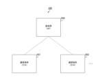
- FIG. 1 is a diagram illustrating a configuration example of a wireless communication system 100 in an embodiment of the present technology.
- This wireless communication system 100 includes a base station 200 and one or more communication terminals such as communication terminals 201 and 202.
- This wireless communication system 100 is also called BSS (Basic Service Set).
- the base station 200 is a wireless station that performs wireless communication with communication terminals connected to itself.
- the base station 200 is also called an access point or a base unit.
- the IEEE802.11 standard is used as the communication standard. For example, the next generation standard after IEEE802.11be is used. Further, a signal from the communication terminal to the base station 200 is an uplink signal, and a signal from the base station 200 to the communication terminal is a downlink signal.
- the communication terminals 201 and 202 are wireless stations that are connected to the base station 200 through association processing or the like and perform wireless communication with the base station 200. These communication terminals are also called slave devices. Further, it is assumed that while a certain communication terminal is transmitting an uplink signal, another communication terminal can multiplex another uplink signal onto that signal using the NOMA method. This NOMA multiplexing is used, for example, when transmitting signals requiring low delay.
- the uplink signal that allows multiplexing using the NOMA method will be referred to as a "NOMA target signal”, and the communication terminal that is the source thereof will be referred to as a "NOMA target terminal”.
- the uplink signal multiplexed with the NOMA signal by the NOMA method is referred to as a "NOMA signal”
- the communication terminal that is the source thereof is referred to as a "NOMA terminal”.
- FIG. 2 is a block diagram showing a configuration example of the communication terminal 201 in the first embodiment of the present technology.
- This communication terminal 201 includes a control section 211, a power supply section 212, and a communication section 220.
- the communication unit 220 includes a radio control device 221, a data processing unit 222, a modulation/demodulation unit 223, a signal processing unit 224, a channel estimation unit 225, and one or more antennas such as antennas 213 and 214.
- the communication unit 220 includes one or more wireless interface units such as wireless interface units 226 and 227, and one or more amplifier units such as amplifier units 228 and 229. An amplifier section is connected to each of the wireless interface sections, and an antenna is connected to each of the amplifier sections. Note that the configurations of base station 200 and communication terminal 202 are similar to communication terminal 201.
- the control unit 211 controls the entire communication terminal 201.
- the power supply unit 212 is configured with a battery or a fixed power supply, and supplies power to the communication terminal 201. At least a portion of the control unit 211 and the communication unit 220 can be realized by LSI (Large Scale Integration).
- a wireless control device 221 is used to exchange signals between each section within the communication section 220 and the control section 211.
- the radio control device 221 also schedules packets in the data processing section 222, sets parameters for the radio interface section and the amplifier section, and controls transmission power.
- the radio control device 221 determines the transmission position of the NOMA signal, Obtain from that reference position.
- the reference position is a position used as a reference when acquiring the transmission position of the NOMA signal in at least one of the frequency domain and the time domain.
- the radio control device 221 controls the radio interface unit 226 and the like to transmit the NOMA signal from its transmission position.
- the communication terminal 201 can multiplex signals using the NOMA method at a transmission position determined by the terminal itself based on the reference position information.
- the radio control device 221 transmits a NOMA target signal upon receiving a downlink signal including the reference position. Details of the sequence when multiplexing using the NOMA method will be described later.
- the data processing unit 222 performs processing in the MAC (Media Access Control) layer. During transmission, the data processing unit 222 generates a packet by adding a MAC header, an error detection code, etc. to upper layer data such as the LLC (Logical Link Control) layer from the radio control device 221. The data processing section 222 then supplies the processed packet to the modulation/demodulation section 223.
- MAC Media Access Control
- LLC Logical Link Control
- the data processing unit 222 performs MAC header analysis, packet error detection, reorder processing, etc. on the packet from the modulation/demodulation unit 223, and sends the processed data via the radio control device 221. and then supply it to the upper layer.
- the modulation/demodulation section 223 performs modulation and demodulation. At the time of transmission, the modulation/demodulation section 223 performs encoding, interleaving, and modulation on the packet from the data processing section 222 based on the coding and modulation method set by the radio control device 221, and generates a data symbol stream. do. Then, the modulation/demodulation section 223 supplies the data symbol stream to the signal processing section 224.
- the modulation/demodulation section 223 performs decoding, deinterleaving, and demodulation on the data symbol stream from the signal processing section 224 corresponding to that during transmission, and supplies the processed packets to the data processing section 222. .
- the signal processing unit 224 performs various signal processing. During transmission, this signal processing unit 224 performs signal processing for spatial separation on the input from the modulation/demodulation unit 223 as necessary, and transmits the obtained one or more transmission symbol streams to the wireless interface unit 226 or 227.
- the signal processing unit 224 performs signal processing on the received symbol streams from the wireless interface units 226 and 227, performs spatial decomposition of the stream as necessary, and supplies the stream to the modulation/demodulation unit 223.
- the signal processing unit 224 performs interference cancellation processing on the input from the wireless interface unit and extracts a desired signal from the superimposed signals.
- Complex channel gain information from the channel estimator 225 is used in this interference cancellation process.
- the channel estimation unit 225 calculates complex channel gain information of the transmission path from the preamble part and the training signal part of the input signal from each wireless interface part.
- the calculated complex channel gain information is supplied to the modulation/demodulation section 223 and the signal processing section 224 and used for spatial processing.
- the wireless interface units 226 and 227 mutually convert analog signals and digital signals. During transmission, these wireless interface units convert the digital signal from the signal processing unit 224 into an analog signal, perform filtering and up-conversion, and send the signal to the corresponding amplifier unit.
- the wireless interface section down-converts the analog signal at the time of reception, converts it into a digital signal, and supplies it to the channel estimation section 225 and the signal processing section 224.
- the amplifier sections 228 and 229 are for amplifying analog signals. During transmission, these amplifier sections amplify analog signals from the corresponding wireless interface sections to a predetermined power level, and supply the amplified signals to the corresponding antennas. Further, during reception, the amplifier section amplifies the analog signal from the corresponding antenna to a predetermined power and supplies it to the corresponding wireless interface section.
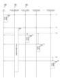
- FIG. 3 is a sequence diagram illustrating an example of a communication method of the wireless communication system 100 according to the first embodiment of the present technology.
- the sequence shown in the figure is started when performing multiplex communication using the NOMA method without prior arrangement of transmission timing (in other words, asynchronous).
- NOMA mode The mode in which this asynchronous multiplex communication is performed.
- the base station 200 transmits a notification signal 501 notifying the transition to NOMA mode to each of the communication terminals under its control.
- this broadcast signal 501 can also be transmitted by the base station 200 in response to a request from a communication terminal.
- the notification signal 501 includes information indicating a transition to NOMA mode, information indicating a reference position, and step information indicating a unit for shifting from the reference position in at least one of the frequency domain and the time domain. including. The specific contents and storage location of this information will be described later.
- the BSS including the base station 200 shifts to NOMA mode.
- the notification signal 501 may be configured not to include step information. Further, a plurality of reference positions can be stored in the notification signal 501.
- a communication terminal transmits an uplink signal (ie, a NOMA target signal) that allows multiplexing using the NOMA method when one or more of the following conditions is satisfied.
- an uplink signal ie, a NOMA target signal
- the NOMA signal is longer than a certain length.
- the NOMA signal is not a signal that requires high reliability.
- the NOMA terminal can transmit an uplink signal (that is, a NOMA signal) that is multiplexed with the NOMA target signal using the NOMA method.
- a NOMA signal that is, a NOMA signal
- the communication terminal 201 functions as the NOMA terminal STA#0, and N (N is an integer) communication terminals including the communication terminal 202 function as the NOMA terminals STA#1 to STA#N.
- the NOMA target terminal STA#0 transmits the NOMA target signal 505 to the base station 200 and each of the NOMA terminals.
- This NOMA target signal 505 includes information indicating that it is a NOMA target signal.
- the NOMA target terminal STA#0 stores the changed step information in the NOMA target signal 505 and transmits it. be able to. Furthermore, if the broadcast signal 501 does not include step information, the NOMA target terminal STA#0 stores the step information in the NOMA target signal 505 and transmits it.
- the broadcast signal 501 includes step information, and the NOMA target signal 505 does not include step information.
- the notification signal 501 includes the step information before the change, and the NOMA target signal 505 includes the step information after the change.
- the broadcast signal 501 does not include step information, and the NOMA signal 505 includes step information.
- the NOMA terminal STA#0 when transmitting the NOMA signal 505, the NOMA terminal STA#0 performs processing to increase interference resistance for the signal portion of the NOMA signal 505 that may be multiplexed. is desirable.
- processing for increasing interference resistance include the following three.
- (Process 1) For signal portions that may be multiplexed, set MCS (Modulation and Channel Coding Scheme) lower than for other portions.
- (Process 2) Invalidate some RUs (Resource Units) of the signal portion that may be multiplexed so that they are not used.
- (Process 3) Duplicate the same data within a signal portion that may be multiplexed.
- the NOMA target terminal STA#0 may perform only one of these processes, or may perform a combination of two or more.
- each NOMA terminal obtains the transmission position of the NOMA signal from the reference position and step information. For example, the NOMA terminal generates a pseudo-random number, and calculates, as the transmission position, a position shifted from the reference position in the frequency/time domain by a value obtained by multiplying the pseudo-random number by the unit indicated by the step information. Pseudo-random numbers are generated by, for example, a linear congruential method or a linear feedback shift register.
- T send T ref +R ⁇ T step ...Formula 1
- the method for calculating the transmission position is not limited to Formula 1.
- the NOMA terminal can use the remaining BO (BackOff) counter number or an index calculated from an AID (Association Identifier) as a pseudorandom number instead of a pseudorandom number generated by a linear congruential method or the like.
- the index is calculated, for example, from the remainder obtained by dividing the AID by the number of communication terminals.
- the transmission position on the frequency axis is also calculated by the same calculation. Thereby, a position shifted by a random value within a predetermined range along at least one of the time axis and the frequency axis is specified as the transmission position.
- the broadcast signal may include range information indicating the range of the transmission position or the range of the pseudorandom number R.
- NOMA terminal STA#1 calculates timing T11 from timing T10 using Equation 1, and transmits NOMA signal 506 to base station 200 over a transmission period after that timing.
- NOMA terminal STA#2 calculates timing T12 from timing T10 using Equation 1, and transmits NOMA signal 507 to base station 200 after that timing.
- NOMA terminal STA#N calculates timing T21 from timing T20 using Equation 1, and transmits NOMA signal 508 to base station 200 over the transmission period after that timing. For example, if timing T10 has passed by the time NOMA terminal STA#N generates the transmission signal, timing T20 is used in Equation 1.
- the base station 200 When the base station 200 receives the NOMA signal, it performs interference cancellation processing on the NOMA signal and the NOMA signals from each NOMA terminal, detects each signal, and performs decoding processing.
- each NOMA terminal transmits a NOMA signal from the same transmission position, even if a random power offset is applied, more signals than expected will be multiplexed when multiplexing using the NOMA method. Interference may become large. In this case, the receiving side may not be able to decode the signal, and there is a risk that retransmission may occur due to reception failure, increasing delay.
- each NOMA terminal acquires a transmission position shifted from the reference position and transmits the NOMA signal, so when multiplexing asynchronously, more signals than expected are multiplexed. It is possible to suppress interference from increasing. Thereby, it is possible to suppress the occurrence of retransmission due to reception failure. Furthermore, by performing communication asynchronously, it is possible to reduce signaling overhead for determining signal transmission timing.
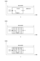
- FIG. 4 is a diagram for explaining interference countermeasures in the first embodiment of the present technology. As described above, it is desirable that the NOMA target terminal STA#0 performs processing to increase the interference resistance of the signal portion of the NOMA target signal 505 that may be multiplexed.
- the vertical axes of a, b, and c indicate frequency, and the horizontal axis indicates time. Moreover, a black circle indicates a reference position. Moreover, the arrow indicates the direction of shift.
- the rectangular portion in which "NOMA" is written indicates the NOMA signal. A portion surrounded by a dotted line indicates a signal portion where the NOMA signal may be multiplexed.
- the NOMA target terminal can execute process 1 of lowering the MCS for a signal portion that may be multiplexed than for other portions.
- the NOMA target terminal can also set the MCS lower than the value defined in the communication standard for a signal portion that may be multiplexed.
- the NOMA target terminal can also perform process 2 of invalidating some RUs of the signal portion that may be multiplexed so as not to use them.
- the diagonally shaded portion b in the figure indicates an invalidated RU.
- the NOMA target terminal can also perform process 3 of duplicating the same data within a signal portion that may be multiplexed.
- the gray area c in the figure is data that is a copy of the white area on the left side.
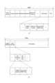
- FIG. 5 is a diagram illustrating a configuration example of a frame within a broadcast signal from base station 200 in the first embodiment of the present technology.
- the broadcast signal includes a PPDU (PLCP Protocol Data Unit), and the PPDU (ie, PHY frame) includes an MPDU (MAC Protocol Data Unit).
- This MPDU ie, MAC frame
- This MPDU includes a "Frame Control” field, a "Duration” field, an "Address” field, a "Sequence Control” field, a frame body, a "FCS (Frame Check Sequence)” field, and the like.
- the format of the MPDU depends on the type of communication standard, and may further include an "HT (High Throughput) Control" field.
- the frame body of the MPDU in the broadcast signal includes a "NOMA Mode” field, a "Reference Position” field, and a "NOMA STEP” field.
- the "NOMA Mode” field stores information indicating that the wireless communication system 100 has shifted to the NOMA mode. This information may be managed with a 1-bit flag, or may be defined separately from other NOMA communications. Further, a part (at least one or two of these) of "NOMA Mode", “Reference Position", and "NOMA STEP" and the rest may be transmitted in separate MPDUs or PPDUs.
- the reference position is stored in the “Reference Position” field. For example, the beginning of the packet, the midamble, or the beginning of the signal (ie, information in the payload) is used as the reference position.
- the "NOMA STEP" field stores step information indicating the unit for shifting from the reference position.
- step information is defined by a fixed time length and a fixed frequency shift length.
- the fixed time length information for example, information specifying one of a plurality of predefined time lengths or a multiple of a predefined minimum fixed time length is written.
- parameters (coefficients, etc.) used for calculation of the fixed time length from the packet length are described.
- information on the frequency shift length information specifying the size of a frequency block consisting of a plurality of predefined subcarriers and a multiple of a predefined minimum frequency block are described.
- FIG. 6 is a diagram illustrating an example of a reference position within a notification signal according to the first embodiment of the present technology. At least one of the following three types can be stored in the "Reference Position" field.
- (Type 1) A reference position common to all communication terminals connected to a base station.
- (Type 2) A reference position common to a predetermined number of communication terminals within a predetermined group.
- (Type 3) A reference position individually assigned to a predetermined communication terminal.
- a indicates a configuration in which only one type is stored
- "Reference Position #1" and “Reference Position #2” indicate reference positions common to all communication terminals. Only one common reference position or two or more of these common reference positions may be stored.
- b in the figure indicates a configuration in which two types are stored, and "Reference Position for Group#1" and “Reference Position for Group#2" indicate a common reference position for a predetermined number of communication terminals in each group. . There may be one group, or two or more groups.
- c indicates a configuration in which three types are stored, and "Reference Position for STA#1" indicates a reference position individually assigned to communication terminal STA#1. It is also possible to individually assign a reference position to each of two or more communication terminals.
- each communication terminal When multiple types of reference positions are stored, each communication terminal, for example, if there is a reference position individually assigned to itself, uses that reference position with the highest priority. Further, if each communication terminal has a reference position for the group to which it belongs, it uses it with priority over a reference position common to all communication terminals.
- FIG. 7 is a diagram illustrating an example of step information in a notification signal in the first embodiment of the present technology.
- the "NOMA STEP" field in the broadcast signal includes a "Time Domain NOMA STEP” field and a "Freq Domain NOMA STEP” field.
- the "Time Domain NOMA STEP” field stores information indicating the unit (fixed time length, etc.) to be shifted from the reference position in the time domain.
- the "Freq Domain NOMA STEP” field stores information indicating the unit (frequency shift length, etc.) to be shifted from the reference position in the frequency domain.
- FIG. 8 is a diagram illustrating an example of the structure of a frame in a NOMA target signal from a NOMA target terminal in the first embodiment of the present technology.
- the NOMA signal includes a PPDU (PHY frame), and the PPDU includes a "Legacy Preamble” field, a "Post BE SIG” field, and a frame body.
- the "Legacy Preamble” field stores the preamble signal used in the previous communication standard.
- the "Post BE SIG” field stores various information regarding the signal (SIGNAL) stored in the frame body, and its format is determined by the next generation communication standard after IEEE802.11be.
- the "Post BE SIG” field includes the "MU Common info” field and the "MU User Info” field.
- the “MU Common info” field stores information common to each communication terminal in the wireless communication system 100. This field includes, for example, a "NOMA Indicator” field and a "NOMA Step” field.
- the "NOMA Indicator” field stores information indicating that the signal is a signal that allows multiplexing using the NOMA method (that is, a signal subject to NOMA).
- the "NOMA Step” field is provided as necessary. For example, when the NOMA target terminal changes step information, the changed step information is stored in the "NOMA Step” field. Furthermore, if the broadcast signal from base station 200 does not include step information, the NOMA target terminal generates step information and stores it in the "NOMA Step” field in the NOMA target signal. Note that "NOMA Indicator” and “NOMA Step” may be transmitted in separate MPDUs or PPDUs.
- the value indicated by the step information may have to be changed depending on the signal length of the NOMA signal and the allowable amount of interference based on SINR (Signal to Interference plus Noise Ratio). Step information is stored in .
- the NOMA terminal acquires the transmission position from the reference position and transmits the NOMA signal from the transmission position, more signals than expected are multiplexed. It is possible to suppress interference from increasing. Thereby, it is possible to suppress the occurrence of retransmission due to reception failure.
- the communication terminal shifts from the reference position in both the frequency domain and the time domain, but it is also possible to shift in only one of them.
- the wireless communication system 100 according to the first modification of the first embodiment differs from the first embodiment in that the position is shifted from the reference position only in the time domain.
- FIG. 9 is a diagram illustrating an example of the structure of a frame in the first modification of the first embodiment of the present technology.
- a indicates an example of the configuration of a MAC frame within a broadcast signal from the base station 200.
- b in the same figure shows an example of the structure of a PHY frame within the NOMA target signal from the NOMA target terminal.
- the MAC frame in the broadcast signal includes a "Time Domain NOMA STEP” field, but does not include a "Freq Domain NOMA STEP” field.
- the PHY frame within the NOMA target signal similarly includes the "Time Domain NOMA STEP” field, but does not include the "Freq Domain NOMA STEP” field.
- the communication terminal shifts from the reference position in both the frequency domain and the time domain, but it is also possible to shift from the reference position in only one of them.
- the wireless communication system 100 according to the second modification of the first embodiment differs from the first embodiment in that it is shifted from the reference position only in the frequency domain.
- FIG. 10 is a diagram illustrating a configuration example of a frame in a second modification of the first embodiment of the present technology.
- a indicates an example of the configuration of a MAC frame within a broadcast signal from the base station 200.
- b in the same figure shows an example of the structure of a PHY frame within the NOMA target signal from the NOMA target terminal.
- the MAC frame in the broadcast signal includes a "Freq Domain NOMA STEP” field, but does not include a "Time Domain NOMA STEP” field.
- the PHY frame within the NOMA target signal similarly includes the "Freq Domain NOMA STEP” field, but does not include the "Time Domain NOMA STEP” field.
- the NOMA target terminal transmits the NOMA target signal to each of the NOMA terminals.
- the NOMA signal may not reach one or more NOMA terminals due to obstructions or distance, resulting in hidden terminals.
- the wireless communication system 100 of the second embodiment differs from the first embodiment in that multiplexing using the NOMA method is possible even when the NOMA terminal is a hidden terminal.
- FIG. 11 is a sequence diagram illustrating an example of a communication method of the wireless communication system 100 according to the second embodiment of the present technology.
- the NOMA target terminal STA#0 When the broadcast signal 501 is transmitted from the base station 200, the NOMA target terminal STA#0 generates a polling signal 502 at timing T2 and transmits it to the base station 200.
- This polling signal includes "NOMA Indicator” and "NOMA Step” illustrated in FIG.
- the base station 200 extracts the step information "NOMA Step” from the polling signal and stores it in the response signal 503 in response to the polling signal. Then, base station 200 transmits the response signal to each communication terminal over a transmission period after timing T3.
- the NOMA target terminal STA#0 transmits the NOMA target signal 505 to the base station 200 and each of the NOMA terminals.
- Each of the NOMA terminals extracts step information from the response signal 503 or the NOMA target signal 505, and obtains the transmission position from the step information.
- the NOMA target signal from the NOMA target terminal STA #0 does not reach the NOMA terminal STA #1, the response signal 503 from the base station 200 does arrive, so step information can be extracted from the response signal. Thereby, even if the NOMA terminal becomes a hidden terminal, multiplexing using the NOMA method can be performed.
- FIG. 12 is a diagram illustrating a configuration example of a notification signal in the second embodiment of the present technology.
- the "Reference Position" field in the broadcast signal further includes a "Reference Position for Hidden Node” field as necessary.
- This “Reference Position for Hidden Node” field can store a reference position assigned to the hidden terminal.
- a hidden terminal to which a reference position in the "Reference Position for Hidden Node" field is assigned uses that reference position with the highest priority.
- the base station 200 since the base station 200 transmits a response signal to each NOMA terminal in response to a polling signal from a NOMA target terminal, there is no hidden terminal among the NOMA terminals.
- multiplexing can be performed using the NOMA method.
- the communication unit 220 (communication module, etc.) that performs wireless communication is provided in the wireless communication devices such as the base station 200, the communication terminal 201, and the communication terminal 202.
- the module may also be provided within the wireless communication device.
- FIG. 13 is a block diagram showing a configuration example of a wireless communication device 750 used as a first application example. Note that this wireless communication device 750 may be any of the base station 200, communication terminal 201, and communication terminal 202 described above.
- a wireless communication device 750 includes an Internet connection module 751, an information input module 752, a device control module 753, an information output module 754, and a wireless communication module 755. Note that the wireless communication device 750 may include only necessary modules.
- the Internet connection module 751 is configured to implement functions such as a communication modem for connecting to the Internet when operating as an access point (such as the base station 200) under the control of the device control module 753.
- the Internet connection module 751 implements a connection to the Internet via a public communication line and an Internet service provider.
- the information input module 752 outputs information conveying instructions input by the user to the device control module 753.
- the information input module 752 includes push buttons, a keyboard, a mouse, a touch panel, and the like.
- Information input module 752 may include voice input functionality.
- the device control module 753 includes a CPU, ROM (Read Only Memory), RAM (Random Access Memory), and the like.
- the device control module 753 executes a program stored in a ROM or the like, causes an application to function in an upper layer, and controls the device to operate as an access point or a wireless communication device of a user terminal.
- the information output module 754 outputs information regarding the operating state of the wireless communication device 750, which is supplied from the device control module 753, or information obtained via the Internet.
- the information output module 754 includes a display element such as an LED (Light Emitting Diode), a liquid crystal panel, or an organic display, or a speaker that outputs audio or music.
- the information output module 754 displays or notifies the user of necessary information.
- the wireless communication module 755 transmits data supplied from the device control module 753 to other wireless communication devices by performing wireless communication.
- the wireless communication module 755 receives data transmitted from other wireless communication devices by performing wireless communication, and outputs the received data to the device control module 753.
- the wireless communication module 755 may operate as the base station 200 in FIG. 1, or may operate as the communication terminal 201 or 202.
- FIG. 14 is a block diagram showing a configuration example of a wireless communication module 755 of a wireless communication device 750 used as a first application example.
- a wireless communication module 755 includes an interface 801, a transmission buffer 802, a frame construction section 803, a communication control section 804, and a signal transmission processing section 805.
- the wireless communication module 755 also includes a high frequency processing section 807, antennas 808-1 and 808-2, a signal reception processing section 809, a frame analysis section 810, and a reception buffer 811.
- the interface 801 functions as an interface for exchanging information input by the user supplied from the device control module 753 and data supplied from the Internet in a predetermined signal format.
- the interface 801 outputs information and data supplied from the device control module 753 to the transmission buffer 802 and the communication control unit 804.
- the interface 801 outputs information and data supplied from the reception buffer 811 to the device control module 753.
- the transmission buffer 802 When the transmission buffer 802 receives information input from the user or data to be transmitted, the transmission buffer 802 temporarily stores the received information or data.
- the frame construction unit 803 constructs a data frame or an Ack frame according to instructions from the communication control unit 804 using the data stored in the transmission buffer 802 and the Ack information supplied from the communication control unit 804.
- the data frame is, for example, a MAC layer protocol data unit (MPDU) frame or an A-MPDU (aggregated MPDU) frame.
- Frame construction section 803 outputs the constructed frame to signal transmission processing section 805.
- the communication control unit 804 manages operations for transmitting and receiving data and Ack information based on information supplied from the interface 801 and the frame analysis unit 810.
- the communication control unit 804 grasps frame construction and data transmission/reception status, and controls the frame construction unit 803, signal transmission processing unit 805, and signal reception processing unit 809.
- the signal transmission processing unit 805 performs encoding processing on the data to be transmitted, and outputs the encoded data to the high frequency processing unit 807.
- the high frequency processing unit 807 performs predetermined high frequency processing on the data supplied from the signal transmission processing unit 805, and constructs a signal in each frequency band among the plurality of frequency bands. High frequency processing unit 807 transmits the constructed signal to the wireless communication device of the communication partner via antennas 808-1 and 808-2.
- the high frequency processing unit 807 receives signals in each frequency band transmitted from the wireless communication device of the communication partner via antennas 808-1 and 808-2, and outputs the received signals to the signal reception processing unit 809. do.
- the signal reception processing section 809 processes the signal supplied from the high frequency processing section 807 and outputs it to the frame analysis section 810.
- the frame analysis unit 810 extracts a predetermined data frame from the received data, and extracts various information and data such as header information, delimiter, and payload from the Ack frame. Frame analysis section 810 outputs the extracted information to communication control section 804 and outputs the extracted data to reception buffer 811.
- the reception buffer 811 stores data supplied from the frame analysis section 810.
- the wireless communication device 750 described above may be implemented as a mobile terminal such as a smartphone, a tablet PC (Personal Computer), a notebook PC, a portable game terminal, or a digital camera. Further, the above-described wireless communication device 750 may be realized as a fixed terminal such as a television receiver, a printer, a digital scanner, or a network storage, or a vehicle-mounted terminal such as a car navigation device. Furthermore, the wireless communication device 750 may be realized as a smart meter, a vending machine, a remote monitoring device, or an M2M (Machine To Machine Communication) terminal such as a POS (Point Of Sale) terminal. Furthermore, the wireless communication device 750 may be a wireless communication module (eg, an integrated circuit module configured with one die) mounted on these terminals.
- a wireless communication module eg, an integrated circuit module configured with one die
- the wireless communication device 750 may be realized as a wireless LAN access point (wireless base station) with or without a router function. Furthermore, the wireless communication device 750 may be implemented as a mobile wireless LAN router. Furthermore, the wireless communication device 750 may be a wireless communication module (eg, an integrated circuit module comprised of one die) mounted on these devices.
- a wireless communication module eg, an integrated circuit module comprised of one die
- Second application example> In the first application example described above, a module other than the wireless communication module is provided in the wireless communication device, but in this second application example, the wireless communication device is applied to a smartphone.
- FIG. 15 is a block diagram showing a configuration example of a wireless communication device used as a second application example.
- this smartphone 900 may be any of the base station 200, communication terminal 201, and communication terminal 202 described above.
- a smartphone 900 includes a processor 901, a memory 902, a storage 903, an external connection interface 904, a camera 906, a sensor 907, a microphone 908, an input device 909, and a display device 910.
- the smartphone 900 also includes a speaker 911, a wireless communication interface 913, an antenna switch 914, an antenna 915, a bus 917, a battery 918, and an auxiliary controller 919.
- the processor 901 may be, for example, a CPU or a SoC (System on Chip), and limits the functions of the application layer and other layers of the smartphone 900.
- SoC System on Chip
- Memory 902 includes RAM and ROM, and stores programs and data executed by processor 901.
- the storage 903 includes a storage medium such as a semiconductor memory or a hard disk.
- the external connection interface 904 is an interface for connecting an external device such as a memory card or a USB (Universal Serial Bus) device to the smartphone 900.
- an external device such as a memory card or a USB (Universal Serial Bus) device to the smartphone 900.
- USB Universal Serial Bus
- the camera 906 has an imaging device such as a CCD (Charge Coupled Device) or a CMOS (Complementary Metal Oxide Semiconductor), and generates a captured image.
- an imaging device such as a CCD (Charge Coupled Device) or a CMOS (Complementary Metal Oxide Semiconductor), and generates a captured image.
- the sensor 907 includes a sensor group such as a positioning sensor, a gyro sensor, a geomagnetic sensor, and an acceleration sensor.
- a sensor group such as a positioning sensor, a gyro sensor, a geomagnetic sensor, and an acceleration sensor.
- the microphone 908 converts the audio input to the smartphone 900 into an audio signal.
- the input device 909 includes, for example, a touch sensor that detects a touch on the screen of the display device 910, a keypad, a keyboard, a button, or a switch, and receives operations or information input from the user.
- the display device 910 has a screen such as a liquid crystal display (LCD) or an organic light emitting diode (OLED) display, and converts the audio signal output from the smartphone 900 into audio.
- LCD liquid crystal display
- OLED organic light emitting diode
- the wireless communication interface 913 supports one or more wireless LAN standards such as IEEE802.11a, 11b, 11g, 11ac, and 11ad, and performs wireless communication.
- the wireless communication interface 913 communicates with other devices via a wireless LAN access point. Furthermore, the wireless communication interface 913 directly communicates with other devices in an ad hoc mode or a direct communication mode such as Wi-Fi Direct.
- Wi-Fi Direct unlike ad hoc mode, one of the two terminals operates as an access point, but communication is performed directly between these terminals.
- the wireless communication interface 913 typically includes a baseband processor, an RF (Radio Frequency) circuit, a power amplifier, and the like.
- the wireless communication interface 913 may be a one-chip module that integrates a memory that stores a communication control program, a processor that executes the program, and related circuits.
- the wireless communication interface 913 may support other types of wireless communication methods such as a short-range wireless communication method, a close proximity wireless communication method, or a cellular communication method.
- the antenna switch 914 switches the connection destination of the antenna 915 between a plurality of circuits (for example, circuits for different wireless communication systems) included in the wireless communication interface 913.
- Antenna 915 has a single antenna element or multiple antenna elements (for example, multiple antenna elements that constitute a MIMO (Multiple Input Multiple Output) antenna), and is used for transmitting and receiving wireless signals by wireless communication interface 913. be done.
- MIMO Multiple Input Multiple Output
- the smartphone 900 is not limited to the example in FIG. 15, and may include a plurality of antennas (for example, a wireless LAN antenna, a close proximity wireless communication system antenna, etc.). In that case, antenna switch 914 may be omitted from the configuration of smartphone 900.
- antenna switch 914 may be omitted from the configuration of smartphone 900.
- Bus 917 connects processor 901, memory 902, storage 903, external connection interface 904, camera 906, sensor 907, microphone 908, input device 909, display device 910, speaker 911, wireless communication interface 913, and auxiliary controller 919 to each other. .
- the battery 918 supplies power to each block of the smartphone 900 shown in FIG. 15 via power supply lines partially indicated by broken lines in the figure.
- the auxiliary controller 919 operates the minimum necessary functions of the smartphone 900, for example, in sleep mode.
- the communication unit 220 illustrated in FIG. 2 may be implemented in the wireless communication interface 913. Also, at least some of these functions may be implemented in processor 901 or auxiliary controller 919.
- the smartphone 900 may operate as a wireless access point (software access point) by the processor 901 executing the access point function at the application level.
- the wireless communication interface 913 may have a wireless access point function.
- the smartphone 900 may operate as a wireless relay device (software relay device) by having the processor 901 execute a relay function at an application level.
- the smartphone 900 may include a biometric authentication section (fingerprint authentication, palm shape authentication, voice authentication, blood vessel authentication, face authentication, iris authentication, retina authentication).
- a biometric authentication section fingerprint authentication, palm shape authentication, voice authentication, blood vessel authentication, face authentication, iris authentication, retina authentication.
- the smartphone 900 information is displayed from at least one of the display device 910 and the speaker 911 based on communication with an external device through the wireless communication interface 913.
- the result of synchronization according to the present technology may be output as information from at least one of the display device 910 and the speaker 911.
- the wireless communication device is applied to a smartphone, but in this third application example, the wireless communication device is applied to a vehicle-mounted device.
- FIG. 16 is a block diagram showing a configuration example of a wireless communication device used as a third application example. Note that this wireless communication device may be any of the base station 200, communication terminal 201, and communication terminal 202 described above.
- an on-vehicle device 920 includes a processor 921, a memory 922, a GNSS (Global Navigation Satellite System) module 924, a sensor 925, a data interface 926, and a content player 927.
- In-vehicle device 920 also includes a storage medium interface 928, an input device 929, a display device 930, a speaker 931, a wireless communication interface 933, an antenna switch 934, an antenna 935, and a battery 938.
- GNSS Global Navigation Satellite System
- the processor 921 may be, for example, a CPU or an SoC, and controls the navigation function and other functions of the in-vehicle device 920. Furthermore, the processor 921 can also control the drive system of the vehicle, such as the brake, accelerator, or steering, based on information obtained through communication based on the present technology.
- Memory 922 includes RAM and ROM, and stores programs and data executed by processor 921.
- the GNSS module 924 measures the position (eg, latitude, longitude, and altitude) of the on-vehicle device 920 using GNSS signals received from GNSS satellites.
- the sensor 925 includes a group of sensors such as a gyro sensor, a geomagnetic sensor, and an atmospheric pressure sensor.
- the data interface 926 is connected to the in-vehicle network 941 via a terminal (not shown), for example, and acquires data generated on the vehicle side, such as in-vehicle data.
- the content player 927 plays back content stored on a storage medium (for example, a CD (Compact Disc) or a DVD (Digital Versatile Disc)) inserted into the storage medium interface 928.
- a storage medium for example, a CD (Compact Disc) or a DVD (Digital Versatile Disc)
- the input device 929 includes, for example, a touch sensor that detects a touch on the screen of the display device 930, a button, or a switch, and receives operations or information input from the user.
- the display device 930 has a screen such as an LCD or OLED display, and displays navigation functions or images of the content to be played.
- the speaker 931 outputs the navigation function or the audio of the content to be played.
- the navigation function and the function provided by the content player 927 are optional.
- the navigation function and content player 927 may be removed from the configuration of the in-vehicle device 920.
- the wireless communication interface 933 supports one or more wireless LAN standards such as IEEE802.11a, 11b, 11g, 11n, 11ac, and 11ad, and performs wireless communication. In the infrastructure mode, the wireless communication interface 933 communicates with other devices via a wireless LAN access point. Furthermore, the wireless communication interface 933 directly communicates with other devices in an ad hoc mode or a direct communication mode such as Wi-Fi Direct.
- wireless LAN standards such as IEEE802.11a, 11b, 11g, 11n, 11ac, and 11ad
- the wireless communication interface 933 typically includes a baseband processor, an RF circuit, a power amplifier, and the like.
- the wireless communication interface 933 may be a one-chip module that integrates a memory that stores a communication control program, a processor that executes the program, or related circuits.
- the wireless communication interface 933 may support other types of wireless communication methods, such as a short-range wireless communication method, a close proximity wireless communication method, or a cellular communication method.
- the antenna switch 934 switches the connection destination of the antenna 935 between a plurality of circuits included in the wireless communication interface 933.
- the antenna 935 has a single or multiple antenna elements and is used for transmitting and receiving wireless signals by the wireless communication interface 933.
- the in-vehicle device 920 is not limited to the example in FIG. 16, and may include a plurality of antennas 935. In that case, the antenna switch 934 may be omitted from the configuration of the in-vehicle device 920.
- the communication unit 220 illustrated in FIG. 2 may be implemented in the wireless communication interface 933 in the vehicle-mounted device 920 illustrated in FIG. . Further, at least some of these functions may be implemented in the processor 921.
- the wireless communication interface 933 may operate as the above-described wireless communication device 750 and provide wireless connection to a terminal owned by a user riding in the vehicle.
- the present technology may be realized as an in-vehicle system (or vehicle) 940 that includes one or more blocks of the above-described in-vehicle device 920, an in-vehicle network 941, and a vehicle-side module 942.
- the vehicle-side module 942 generates vehicle-side data such as vehicle speed, engine speed, or failure information, and outputs the generated data to the in-vehicle network 941.
- the wireless communication device is applied to a smartphone, but in this fourth application example, the wireless communication device 950 is applied to a wireless communication device 950 having a wired communication interface.
- FIG. 17 is a block diagram showing a configuration example of a wireless access point 950 (wireless communication device) used as a fourth application example. Note that this wireless communication device is used as the base station 200 described above.
- a wireless access point 950 includes a controller 951, a memory 952, an input device 954, a display device 955, a network interface 957, a wireless communication interface 963, an antenna switch 964, and an antenna 965.
- the controller 951 may be, for example, a CPU or a DSP (Digital Signal Processor).
- the controller 951 operates various functions of the IP (Internet Protocol) layer and higher layers of the wireless access point 950 (eg, access restriction, routing, encryption, firewall, log management, etc.).
- Memory 952 includes RAM and ROM, and stores programs executed by controller 951 and various control data (eg, terminal list, routing table, encryption key, security settings, logs, etc.).
- various control data eg, terminal list, routing table, encryption key, security settings, logs, etc.
- the input device 954 includes, for example, buttons and switches, and accepts operations from the user.
- the display device 955 includes an LED lamp and the like, and displays the operational status of the wireless access point 950.
- the network interface 957 is a wired communication interface for connecting the wireless access point 950 to the wired communication network 958.
- Network interface 957 may have multiple connection terminals.
- Wired communication network 958 may be a LAN, such as Ethernet, or may be a WAN.
- the wireless communication interface 963 supports one or more wireless LAN standards, such as IEEE 802.11a, 11b, 11g, 11n, 11ac, and 11ad, and provides wireless connectivity as an access point to nearby terminals.
- wireless LAN standards such as IEEE 802.11a, 11b, 11g, 11n, 11ac, and 11ad
- the wireless communication interface 963 typically includes a baseband processor, an RF circuit, a power amplifier, and the like.
- the wireless communication interface 963 may be a one-chip module that integrates a memory that stores a communication control program, a processor that executes the program, or related circuits.
- the antenna switch 964 switches the connection destination of the antenna 965 between a plurality of circuits included in the wireless communication interface 963.
- the antenna 965 has a single or multiple antenna elements and is used for transmitting and receiving wireless signals by the wireless communication interface 963.
- the communication unit 220 illustrated in FIG. 2 may also be implemented in the wireless communication interface 963. Further, at least some of these functions may be implemented in the controller 951.
- a control unit that determines the transmission position in at least one of the frequency domain and the time domain of the NOMA signal multiplexed with the NOMA signal by the NOMA (Non-orthogonal Multiple Access) method based on a random value.
- a wireless control device comprising: (2) The control unit acquires reference position information indicating a predetermined reference position in at least one of a frequency domain and a time domain, which is included in a signal transmitted from another wireless device, and determines the transmission position. The wireless control device according to (1) above, which determines based on the reference position information.
- the radio control device includes information indicating that the signal is allowed to be multiplexed by the NOMA method.
- the signal includes step information indicating a unit of shift from the reference position.
- the NOMA signal includes step information indicating a unit of shift from the reference position.
- the other wireless device is a base station, The radio control device according to (2), wherein the signal is a response signal of the base station to a predetermined polling signal.
- the reference position includes a reference position common to all communication terminals connected to the base station.
- the radio control device according to any one of (1) to (11), wherein the reference position includes a reference position common to a predetermined number of communication terminals within a predetermined group. (13) The radio control device according to any one of (1) to (12), wherein the reference position includes a reference position individually assigned to a predetermined communication terminal. (14) The radio control device according to any one of (1) to (13), wherein the reference position includes a reference position assigned to a hidden terminal to which the NOMA signal does not reach.
- a first communication terminal that transmits a predetermined NOMA signal
- a second communication terminal comprising a control unit that determines, based on a random value, a transmission position in at least one of the frequency domain and the time domain of the NOMA signal multiplexed with the NOMA signal by the NOMA method; Equipped with a wireless communication system.
- a control procedure for determining the transmission position in at least one of the frequency domain and the time domain of the NOMA signal multiplexed with the NOMA signal by the NOMA method, based on a random value. program.
- a radio control device comprising a control procedure for determining, based on a random value, the transmission position in at least one of the frequency domain and the time domain of the NOMA signal multiplexed with the NOMA signal by the NOMA method. Control method.
- a predetermined reference position in at least one of the frequency domain and the time domain for determining the transmission position in at least one of the frequency domain and the time domain of the NOMA signal multiplexed with the NOMA signal by the NOMA method.
- the radio control device according to any one of (22) to (24), wherein the signal is a polling signal transmitted to the base station.
- the control unit sets MCS (Modulation and Channel Coding Scheme) lower than a predetermined value for a signal portion of the NOMA signal that may be multiplexed.
- MCS Modulation and Channel Coding Scheme
- the wireless control device according to any one of (23) to (25) above.
- the control unit disables some RUs (Resource Units) of a signal portion of the NOMA signal that may be multiplexed. ) to (26).
- the control unit duplicates the same data within a signal portion of the NOMA signal that may be multiplexed.
- the wireless control device according to any one of.
- Radio communication system 200 Base station 201, 202 Communication terminal 211 Control unit 212 Power supply unit 213, 214 Antenna 220 Communication unit 221 Radio control device 222 Data processing unit 223 Modulation/demodulation unit 224 Signal processing unit 225 Channel estimation unit 226, 227 Radio interface unit 228, 229 Amplifier section
Abstract
NOMA方式で多重化を行う無線制御装置において、干渉を抑制する。 無線通信システムは、第1の通信端末と、第2の通信端末とを具備する。第1の通信端末は、所定の被NOMA(Non-orthogonal Multiple Access)方信号を送信する。また、第2の通信端末は、NOMA方式により前記被NOMA信号に多重化されるNOMA信号の周波数領域または時間領域の少なくとも一方の領域内の送信位置を無作為な値に基づいて決定する制御部を備える。
Description
本技術は、無線制御装置に関する。詳しくは、多重化を行う無線制御装置、通信システム、プログラム、および、無線制御装置の制御方法に関する。
従来より、無線LAN(Local Area Network)では、通信端末が信号を送信する際に、送信待機により遅延が生じることがある。この遅延を軽減するために、無線局が他の無線局への信号を送信中に干渉の発生を一部許容する形で別の信号を多重化するNOMA(Non-Orthogonal Multiple Access)方式が用いられることがある。例えば、NOMAが用いられるサブフレームにおいて、ランダムな電力オフセットを適用する無線局が提案されている(例えば、特許文献1参照。)。
上述の従来技術では、ランダムな電力オフセットを適用することにより、送信タイミングなどを事前に打ち合わせることを要しない非同期的な通信を可能にしている。しかしながら、上述の従来技術では、想定以上の数の信号が多重化されて干渉が大きくなり、受信側が信号を復号できなくなるおそれがある。
本技術はこのような状況に鑑みて生み出されたものであり、NOMA方式で多重化を行う無線制御装置において、干渉を抑制することを目的とする。
本技術は、上述の問題点を解消するためになされたものであり、その第1の側面は、NOMA(Non-orthogonal Multiple Access)方式により被NOMA信号に多重化されるNOMA信号の周波数領域または時間領域の少なくとも一方の領域内の送信位置を無作為な値に基づいて決定する制御部を備える無線制御装置である。これにより、干渉が抑制されるという作用をもたらす。
また、この第1の側面において、上記制御部は、他の無線装置から送信される信号に含まれる、周波数領域および時間領域の少なくとも一方の領域内の所定の基準位置を示す基準位置情報を取得し、上記送信位置を上記基準位置情報に基づき決定してもよい。これにより、基準位置に基づいて送信位置が決定されるという作用をもたらす。
また、この第1の側面において、上記制御部は、時間軸および周波数軸の少なくとも一方に沿って上記基準位置から前記無作為な値に基づく量シフトさせた位置を上記送信位置として決定してもよい。これにより、干渉が抑制されるという作用をもたらす。
また、この第1の側面において、上記制御部は、時間軸および周波数軸の少なくとも一方に沿って所定の範囲内で無作為な値に基づく量シフトさせた位置を上記送信位置として決定してもよい。所定範囲内でランダムな位置が決定されるという作用をもたらす。
また、この第1の側面において、上記信号は、上記範囲を示す範囲情報を含むものであってもよい。範囲情報を示す所定範囲内でランダムな位置が特定されるという作用をもたらす。
また、この第1の側面において、上記信号は、上記NOMA方式の通信を行うモードであることを示す情報を含むものであってもよい。これにより、NOMA方式の通信が開始されるという作用をもたらす。
また、この第1の側面において、上記被NOMA信号は、 当該信号に上記NOMA方式によって多重化することを許容する旨を示す情報を含むものであってもよい。これにより、NOMA方式による多重化が行われるという作用をもたらす。
また、この第1の側面において、上記信号は、上記基準位置からシフトさせる単位を示すステップ情報を含むものであってもよい。これにより、報知信号からステップ情報が取り出されるという作用をもたらす。
また、この第1の側面において、上記被NOMA信号は、上記基準位置からシフトさせる単位を示すステップ情報を含むものであってもよい。これにより、被NOMA信号からステップ情報が取り出されるという作用をもたらす。
また、この第1の側面において、上記他の無線装置は基地局であり、上記信号は、所定のポーリング信号に対する上記基地局の応答信号であってもよい。これにより、隠れ端末があってもステップ情報を取得できるという作用をもたらす。
また、この第1の側面において、上記基準位置は、上記基地局に接続された全ての通信端末で共通の基準位置を含むものであってもよい。これにより、共通の基準位置からシフトした位置が取得されるという作用をもたらす。
また、この第1の側面において、上記基準位置は、所定のグループ内の所定数の通信端末で共通の基準位置を含むものであってもよい。これにより、グループ内では、そのグループの基準位置からシフトした位置が取得されるという作用をもたらす。
また、この第1の側面において、上記基準位置は、所定の通信端末に個別に割り当てられた基準位置を含むものであってもよい。これにより、通信端末ごとに個別の基準位置からシフトした位置が取得されるという作用をもたらす。
また、この第1の側面において、上記基準位置は、上記被NOMA信号が届かない隠れ端末に割り当てられた基準位置を含むものであってもよい。これにより、隠れ端末では、個別の基準位置からシフトした位置が取得されるという作用をもたらす。
また、本技術の第2の側面は、所定の被NOMA信号を送信する第1の通信端末と、NOMA方式により上記被NOMA信号に多重化されるNOMA信号の周波数領域または時間領域の少なくとも一方の領域内の送信位置を無作為な値に基づいて決定する制御部を備える第2の通信端末とを具備する無線通信システムである。これにより、無線通信システム内で干渉が抑制されるという作用をもたらす。
以下、本技術を実施するための形態(以下、実施の形態と称する)について説明する。説明は以下の順序により行う。
1.第1の実施の形態(基準位置からシフトさせる例)
2.第2の実施の形態(ポーリング信号に対する応答信号内のステップ情報を用いて基準位置からシフトさせる例)
3.第1の応用例(無線通信モジュール以外のモジュールを無線通信装置に設けた例)
4.第2の応用例(無線通信装置がスマートフォンに適用された例)
5.第3の応用例(無線通信装置が車載装置に適用された例)
6.第4の応用例(無線通信装置が有線通信インターフェースを持つ無線APに適用された例)
1.第1の実施の形態(基準位置からシフトさせる例)
2.第2の実施の形態(ポーリング信号に対する応答信号内のステップ情報を用いて基準位置からシフトさせる例)
3.第1の応用例(無線通信モジュール以外のモジュールを無線通信装置に設けた例)
4.第2の応用例(無線通信装置がスマートフォンに適用された例)
5.第3の応用例(無線通信装置が車載装置に適用された例)
6.第4の応用例(無線通信装置が有線通信インターフェースを持つ無線APに適用された例)
<1.第1の実施の形態>
[無線通信システムの構成例]
図1は、本技術の実施の形態における無線通信システム100の一構成例を示す図である。この無線通信システム100は、基地局200と、通信端末201および202などの1つ以上の通信端末とを含む。この無線通信システム100は、BSS(Basic Service Set)とも呼ばれる。
[無線通信システムの構成例]
図1は、本技術の実施の形態における無線通信システム100の一構成例を示す図である。この無線通信システム100は、基地局200と、通信端末201および202などの1つ以上の通信端末とを含む。この無線通信システム100は、BSS(Basic Service Set)とも呼ばれる。
基地局200は、自身に接続された通信端末との間で無線通信を行う無線局である。基地局200は、アクセスポイントや親機とも呼ばれる。通信規格として、IEEE802.11規格が用いられる。例えば、IEEE802.11be以降の次世代規格が用いられる。また、通信端末から基地局200への信号をアップリンク信号とし、基地局200から通信端末への信号をダウンリンク信号とする。
通信端末201や202は、アソシエーション処理などにより基地局200に接続され、基地局200との間で無線通信を行う無線局である。これらの通信端末は、子機とも呼ばれる。また、ある通信端末がアップリンク信号を送信中に、その信号に他の通信端末がNOMA方式により別のアップリンク信号を多重化することができるものとする。このNOMA方式による多重化は、例えば、低遅延が要求される信号を送信する際に用いられる。
以下、NOMA方式による多重化を許容するアップリンク信号を「被NOMA信号」と称し、その送信元の通信端末を「被NOMA端末」と称する。また、被NOMA信号にNOMA方式により多重化するアップリンク信号を「NOMA信号」と称し、その送信元の通信端末を「NOMA端末」と称する。
[通信端末の構成例]
図2は、本技術の第1の実施の形態における通信端末201の一構成例を示すブロック図である。この通信端末201は、制御部211、電源部212、および、通信部220を備える。通信部220は、無線制御装置221、データ処理部222、変復調部223、信号処理部224、および、チャネル推定部225と、アンテナ213や214などの1つ以上のアンテナとを備える。また、通信部220は、無線インターフェース部226や227などの1つ以上の無線インターフェース部と、アンプ部228や229などの1つ以上のアンプ部とを備える。無線インターフェース部のそれぞれにアンプ部が接続され、アンプ部のそれぞれにアンテナが接続される。なお、基地局200および通信端末202のそれぞれの構成は、通信端末201と同様である。
図2は、本技術の第1の実施の形態における通信端末201の一構成例を示すブロック図である。この通信端末201は、制御部211、電源部212、および、通信部220を備える。通信部220は、無線制御装置221、データ処理部222、変復調部223、信号処理部224、および、チャネル推定部225と、アンテナ213や214などの1つ以上のアンテナとを備える。また、通信部220は、無線インターフェース部226や227などの1つ以上の無線インターフェース部と、アンプ部228や229などの1つ以上のアンプ部とを備える。無線インターフェース部のそれぞれにアンプ部が接続され、アンプ部のそれぞれにアンテナが接続される。なお、基地局200および通信端末202のそれぞれの構成は、通信端末201と同様である。
制御部211は、通信端末201全体を制御するものである。電源部212は、バッテリーや固定電源で構成され、通信端末201に電源を供給するものである。制御部211および通信部220の少なくとも一部は、LSI(Large Scale Integration)により実現することができる。
通信部220において、無線制御装置221は、通信部220内の各部と、制御部211との間で信号の受け渡しを行うものである。また、無線制御装置221は、データ処理部222におけるパケットのスケジューリングを行い、無線インターフェース部およびアンプ部のパラメータ設定および送信電力制御を行う。
さらに、通信端末201をNOMA端末として機能させる場合、無線制御装置221は、所定の基準位置を示す基準位置情報を含むダウンリンク信号を基地局200から受信した際に、NOMA信号の送信位置を、その基準位置から取得する。ここで、基準位置は、周波数領域および時間領域の少なくとも一方の領域内で、NOMA信号の送信位置を取得する際に基準として用いられる位置である。そして、無線制御装置221は、無線インターフェース部226などを制御して、NOMA信号を、その送信位置から送信させる。これにより、通信端末201は、基準位置情報に基づいて端末自身が決定した送信位置にNOMA方式により信号を多重化することができる。
一方、通信端末201を被NOMA端末として機能させる場合、無線制御装置221は、基準位置を含むダウンリンク信号を受信すると被NOMA信号を送信させる。NOMA方式により多重化する際のシーケンスの詳細については後述する。
データ処理部222は、MAC(Media Access Control)層における処理を行うものである。このデータ処理部222は、送信時において、無線制御装置221からのLLC(Logical Link Control)層などの上位層のデータにMACヘッダや誤り検出符号などを付加してパケットを生成する処理を行う。そして、データ処理部222は、処理後のパケットを変復調部223に供給する。
また、データ処理部222は、受信時において、変復調部223からのパケットについて、MACヘッダの解析、パケット誤りの検出やリオーダー処理などを実行し、処理後のデータを、無線制御装置221を介して上位層に供給する。
変復調部223は、変調や復調を行うものである。この変復調部223は、送信時において、無線制御装置221により設定されたコーディングや変調方式に基づいて、データ処理部222からのパケットに対して、エンコード、インターリーブおよび変調を行い、データシンボルストリームを生成する。そして、変復調部223は、そのデータシンボルストリームを信号処理部224に供給する。
また、変復調部223は、受信時において、信号処理部224からのデータシンボルストリームに対して、送信時と対応するデコード、デインターリーブおよび復調を行い、処理後のパケットをデータ処理部222に供給する。
信号処理部224は、各種の信号処理を行うものである。この信号処理部224は、送信時において、変復調部223からの入力について、空間分離に供される信号処理を必要に応じて行い、得られた1つ以上の送信シンボルストリームを無線インターフェース部226や227へ供給する。
また、信号処理部224は、受信時において、無線インターフェース部226や227からの受信シンボルストリームに対して信号処理を行い、必要に応じてストリームの空間分解を行って変復調部223に供給する。
また、信号処理部224は、受信時において、無線インターフェース部からの入力に対して、干渉キャンセル処理を行い、重畳された信号の中から所望の信号を取り出す。この干渉キャンセル処理には、チャネル推定部225からの複素チャネル利得情報が用いられる。
チャネル推定部225は、各無線インターフェース部からの入力信号のうち、プリアンブル部分およびトレーニング信号部分から伝送路の複素チャネル利得情報を算出するものである。算出された複素チャネル利得情報は、変復調部223および信号処理部224に供給され、空間処理に用いられる。
無線インターフェース部226や227は、アナログ信号とデジタル信号とを互いに変換するものである。これらの無線インターフェース部は、送信時において、信号処理部224からのデジタル信号をアナログ信号に変換し、フィルタリングおよびアップコンバートを行い、対応するアンプ部に送出する。
また、無線インターフェース部は、受信時においてアナログ信号に対してダウンコンバートを行い、デジタル信号に変換してチャネル推定部225および信号処理部224に供給する。
アンプ部228や229は、アナログ信号を増幅するものである。これらのアンプ部は、送信時において、対応する無線インターフェース部からのアナログ信号を所定電力まで増幅し、対応するアンテナに供給する。また、アンプ部は、受信時において、対応するアンテナからのアナログ信号を所定電力まで増幅し、対応する無線インターフェース部に供給する。
[無線通信システムの動作例]
図3は、本技術の第1の実施の形態における無線通信システム100の通信方法の一例を示すシーケンス図である。同図のシーケンスは、送信タイミングなどを事前に打ち合わせることの無い(言い換えれば、非同期的な)、NOMA方式による多重化通信を行う際に開始される。この非同期的な多重化通信を行うモードを以下、「NOMAモード」と称する。
図3は、本技術の第1の実施の形態における無線通信システム100の通信方法の一例を示すシーケンス図である。同図のシーケンスは、送信タイミングなどを事前に打ち合わせることの無い(言い換えれば、非同期的な)、NOMA方式による多重化通信を行う際に開始される。この非同期的な多重化通信を行うモードを以下、「NOMAモード」と称する。
タイミングT1において、基地局200は、NOMAモードに移行する旨を報知する報知信号501を配下の通信端末のそれぞれに送信する。なお、この報知信号501は、通信端末からのリクエストに応じて基地局200が送信することもできる。
また、報知信号501は、NOMAモードに移行する旨を示す情報と、基準位置を示す情報と、周波数領域および時間領域の少なくとも一方の領域内で基準位置からシフトさせる際の単位を示すステップ情報とを含む。これらの情報の具体的な内容や格納場所に関しては後述する。報知信号501の送信により、基地局200を含むBSSは、NOMAモードに移行する。なお、報知信号501がステップ情報を含まない構成とすることもできる。また、報知信号501内に複数の基準位置を格納することができる。
通信端末は、次の条件の1つ以上を満たす場合に、NOMA方式による多重化を許容するアップリンク信号(すなわち、被NOMA信号)を送信する。
(条件1)被NOMA信号が一定以上の長さである。
(条件2)被NOMA信号が高信頼性を要求される信号ではない。
(条件1)被NOMA信号が一定以上の長さである。
(条件2)被NOMA信号が高信頼性を要求される信号ではない。
また、被NOMA端末が被NOMA信号の送信中に、NOMA端末は、その被NOMA信号にNOMA方式により多重化するアップリンク信号(すなわち、NOMA信号)を送信することができる。
通信端末201が被NOMA端末STA#0として機能し、通信端末202を含むN(Nは、整数)個の通信端末がNOMA端末STA#1乃至STA#Nとして機能するものとする。
タイミングT2以降において、被NOMA端末STA#0が、被NOMA信号505を基地局200と、NOMA端末のそれぞれとに送信する。この被NOMA信号505は、自身が被NOMA信号である旨を示す情報を含む。
なお、報知信号501がステップ情報を含み、被NOMA端末STA#0がそのステップ情報を変更したい場合、被NOMA端末STA#0は、変更後のステップ情報を被NOMA信号505に格納して送信することができる。また、報知信号501がステップ情報を含まない構成である場合、被NOMA端末STA#0は、ステップ情報を被NOMA信号505に格納して送信する。
まとめると、ステップ情報がどの信号に含まれるかに関して、次の3つのケースが考えられる。
(ケース1)報知信号501がステップ情報を含み、被NOMA信号505はステップ情報を含まない。
(ケース2)報知信号501が変更前のステップ情報を含み、被NOMA信号505が変更後のステップ情報を含む。
(ケース3)報知信号501はステップ情報を含まず、被NOMA信号505がステップ情報を含む。
(ケース1)報知信号501がステップ情報を含み、被NOMA信号505はステップ情報を含まない。
(ケース2)報知信号501が変更前のステップ情報を含み、被NOMA信号505が変更後のステップ情報を含む。
(ケース3)報知信号501はステップ情報を含まず、被NOMA信号505がステップ情報を含む。
また、被NOMA信号505を送信する際に、被NOMA端末STA#0は、その被NOMA信号505のうち多重化される可能性のある信号部分に対して、干渉耐性を高くする処理を行うことが望ましい。干渉耐性を高くする処理として、例えば、次の3つが挙げられる。
(処理1)多重化される可能性のある信号部分について、それ以外の部分よりもMCS(Modulationand channel Coding Scheme)を低くする。
(処理2)多重化される可能性のある信号部分の一部のRU(Resource Unit)を使用しないように無効化する。
(処理3)多重化される可能性のある信号部分内で同一のデータを複製する。
(処理1)多重化される可能性のある信号部分について、それ以外の部分よりもMCS(Modulationand channel Coding Scheme)を低くする。
(処理2)多重化される可能性のある信号部分の一部のRU(Resource Unit)を使用しないように無効化する。
(処理3)多重化される可能性のある信号部分内で同一のデータを複製する。
被NOMA端末STA#0は、これらの処理を1つのみ行ってもよいし、2つ以上を組み合わせて行うこともできる。
被NOMA信号505の送信中に、NOMA端末のそれぞれは、基準位置とステップ情報とからNOMA信号の送信位置を取得する。例えば、NOMA端末は、疑似乱数を生成し、その疑似乱数にステップ情報の示す単位を乗算した値だけ、周波数・時間領域内で基準位置からシフトさせた位置を送信位置として算出する。疑似乱数は、例えば、線形合同法や線形帰還シフトレジスタなどにより生成される。
時間軸上の基準位置をTrefとし、疑似乱数をRとし、ステップ情報の示す時間軸上の単位をTstepとすると、時間軸上の送信位置Tsendは、次の式により算出される。
Tsend=Tref+R×Tstep ・・・式1
Tsend=Tref+R×Tstep ・・・式1
なお、送信位置の算出方法は、式1に限定されない。例えば、NOMA端末は、線形合同法などにより生成した疑似乱数の代わりに、BO(BackOff)残りカウンタ数や、AID(Association Identifier)から算出されるインデックスを疑似乱数として用いることもできる。インデックスは、例えば、AIDを通信端末の個数などにより除算した余りから算出される。
周波数軸上の送信位置も、同様の演算により算出される。これにより、時間軸および周波数軸の少なくとも一方に沿って所定の範囲内で無作為な値の量シフトさせた位置が、送信位置として特定される。なお、報知信号は、送信位置の範囲あるいは疑似乱数Rの範囲を示す範囲情報を含んでもよい。
報知信号501内の時間軸上の基準位置が、タイミングT10およびT20であったものとする。NOMA端末STA#1は、式1によりタイミングT10からタイミングT11を算出し、そのタイミング以降の送信期間に亘ってNOMA信号506を基地局200へ送信する。NOMA端末STA#2は、式1によりタイミングT10からタイミングT12を算出し、そのタイミング以降にNOMA信号507を基地局200へ送信する。
また、NOMA端末STA#Nは、式1によりタイミングT20からタイミングT21を算出し、そのタイミング以降の送信期間に亘ってNOMA信号508を基地局200へ送信する。例えば、NOMA端末STA#Nが送信信号を生成する時点で、タイミングT10を経過していた場合は、式1においてタイミングT20が用いられる。
基地局200は、被NOMA信号を受信した場合、被NOMA信号と、各NOMA端末からのNOMA信号とのそれぞれに対して干渉キャンセル処理を行って各信号を検出し、復号処理を行う。
仮に、NOMA端末のそれぞれが、同一の送信位置からNOMA信号を送信した場合、ランダムな電力オフセットを適用したとしても、NOMA方式により多重化を行った際に、想定以上の信号が多重化されて干渉が大きくなってしまうことがある。この場合、受信側が信号を復号できなくなり、受信失敗により再送が発生して遅延が増大するおそれがある。
これに対して同図の通信方法では、NOMA端末のそれぞれが、基準位置からシフトさせた送信位置を取得してNOMA信号を送信するため、非同期で多重化した際に想定以上の信号が多重化されて干渉が大きくなることを抑制することができる。これにより、受信失敗による再送発生を抑制することができる。また、非同期に通信を行うことにより、信号の送信タイミングを決定するためのシグナリングのオーバーヘッドを削減することができる。
図4は、本技術の第1の実施の形態における干渉対策を説明するための図である。前述したように、被NOMA端末STA#0は、その被NOMA信号505のうち多重化される可能性のある信号部分に対して、干渉耐性を高くする処理を行うことが望ましい。
同図におけるa、bおよびcの縦軸は周波数を示し、横軸は時間を示す。また、黒丸は、基準位置を示す。また、矢印は、シフトした方向を示す。「NOMA」を記載した矩形部分は、NOMA信号を示す。点線で囲まれた部分は、そのNOMA信号が多重化される可能性のある信号部分を示す。
同図におけるaに例示するように、被NOMA端末は、多重化される可能性のある信号部分について、それ以外の部分よりもMCSを低くする処理1を実行することができる。なお、被NOMA端末は、多重化される可能性のある信号部分について、通信規格上、定められた値よりもMCSを低くすることもできる。
また、同図におけるbに例示するように、被NOMA端末は、多重化される可能性のある信号部分の一部のRUを使用しないように無効化する処理2を行うこともできる。同図におけるbの斜線部分は、無効化されたRUを示す。
また、同図におけるcに例示するように、被NOMA端末は、多重化される可能性のある信号部分内で同一のデータを複製する処理3を行うこともできる。同図におけるcの灰色部分は、その左側の白色部分を複製したデータである。
[フレームの構成例]
図5は、本技術の第1の実施の形態における基地局200からの報知信号内のフレームの一構成例を示す図である。報知信号は、PPDU(PLCP Protocol Data Unit)を含み、そのPPDU(すなわち、PHYフレーム)は、MPDU(MAC Protocol Data Unit)を含む。このMPDU(すなわち、MACフレーム)は、「Frame Control」フィールド、「Duration」フィールド、「Address」フィールド、「Sequence Control」フィールド、フレームボディ、「FCS(Frame Check Sequence)」フィールドなどを含む。MPDUのフォーマットは、通信規格の種類に依存し、「HT(High Throughput) Control」フィールドなどをさらに含むこともある。
図5は、本技術の第1の実施の形態における基地局200からの報知信号内のフレームの一構成例を示す図である。報知信号は、PPDU(PLCP Protocol Data Unit)を含み、そのPPDU(すなわち、PHYフレーム)は、MPDU(MAC Protocol Data Unit)を含む。このMPDU(すなわち、MACフレーム)は、「Frame Control」フィールド、「Duration」フィールド、「Address」フィールド、「Sequence Control」フィールド、フレームボディ、「FCS(Frame Check Sequence)」フィールドなどを含む。MPDUのフォーマットは、通信規格の種類に依存し、「HT(High Throughput) Control」フィールドなどをさらに含むこともある。
報知信号内のMPDUのフレームボディは、「NOMA Mode」フィールド、「Reference Position」フィールド、および「NOMA STEP」フィールドを含む。「NOMA Mode」フィールドには、無線通信システム100がNOMAモードに移行した旨を示す情報が格納される。この情報は、1ビットのフラグで管理されてもよいし、他のNOMA通信と区別して定義されてもよい。また、「NOMA Mode」、「Reference Position」、「NOMA STEP」の一部(これらのうち少なくとも一つまたは二つ)と、残りとが別々のMPDUまたはPPDUで送信されても良い。
「Reference Position」フィールドには、基準位置が格納される。例えば、パケットの先頭、ミッドアンブルや、信号(すなわち、ペイロード内の情報)の先頭が基準位置として用いられる。
「NOMA STEP」フィールドには、基準位置からシフトさせる際の単位を示すステップ情報が格納される。例えば、ステップ情報は、固定時間長と固定の周波数シフト長とにより定義される。固定時間長の情報として、例えば、予め定義された複数の時間長のいずれかを指定する情報や、予め定義された最小固定時間長に対する倍数が記載される。あるいは、固定時間長の情報として、その固定時間長をパケット長から算出する演算に用いるパラメータ(係数など)が記載される。
また、周波数シフト長の情報として、予め定義された複数のサブキャリアからなる周波数ブロックのサイズを指定する情報や、予め定義された最小周波数ブロックに対する倍数が記載される。
図6は、本技術の第1の実施の形態における報知信号内の基準位置の一例を示す図である。「Reference Position」フィールドには、次の3種類のうち少なくとも1種類を格納することができる。
(種類1)基地局に接続された全通信端末で共通の基準位置。
(種類2)所定のグループ内の所定数の通信端末で共通の基準位置。
(種類3)所定の通信端末に個別に割り当てられた基準位置。
(種類1)基地局に接続された全通信端末で共通の基準位置。
(種類2)所定のグループ内の所定数の通信端末で共通の基準位置。
(種類3)所定の通信端末に個別に割り当てられた基準位置。
同図におけるaは、1種類のみを格納した構成を示し、「Reference Position#1」および「Reference Position#2」は、全通信端末で共通の基準位置を示す。この共通の基準位置を1つのみ格納してもよいし、2つ以上を格納してもよい。
同図におけるbは、2種類を格納した構成を示し、「Reference Position for Group#1」および「Reference Position for Group#2」は、各グループ内の所定数の通信端末で共通の基準位置を示す。グループは、1つであってもよいし、2つ以上であってもよい。
同図におけるcは、3種類を格納した構成を示し、「Reference Position for STA#1」は、通信端末STA#1に個別に割り当てられた基準位置を示す。2つ以上の通信端末のそれぞれに個別に基準位置を割り当てることもできる。
複数の種類の基準位置を格納した場合、通信端末のそれぞれは、例えば、自身に個別に割り当てられた基準位置があれば、その基準位置を最も優先して用いる。また、通信端末のそれぞれは、自身が属するグループの基準位置があれば、全通信端末で共通の基準位置よりも優先して用いる。
図7は、本技術の第1の実施の形態における報知信号内のステップ情報の一例を示す図である。同図に例示するように、報知信号内の「NOMA STEP」フィールドは、「Time Domain NOMA STEP」フィールドと、「Freq Domain NOMA STEP」フィールドとを含む。「Time Domain NOMA STEP」フィールドには、時間領域内で基準位置からシフトさせる単位(固定時間長など)を示す情報が格納される。「Freq Domain NOMA STEP」フィールドには、周波数領域内で基準位置からシフトさせる単位(周波数シフト長など)を示す情報が格納される。
図8は、本技術の第1の実施の形態における被NOMA端末からの被NOMA信号内のフレームの一構成例を示す図である。被NOMA信号は、PPDU(PHYフレーム)を含み、PPDUは、「Legacy Preamble」フィールド、「Post BE SIG」フィールド、および、フレームボディを含む。
「Legacy Preamble」フィールドには、以前の通信規格で用いられたプリアンブル信号が格納される。「Post BE SIG」フィールドには、フレームボディに格納される信号(SIGNAL)に関する各種の情報が格納され、そのフォーマットは、IEEE802.11be以降の次世代の通信規格で決定される。
例えば、「Post BE SIG」フィールドは、「MU Common info」フィールド、および、「MU User Info」フィールドを含む。「MU Common info」フィールドには、無線通信システム100内の各通信端末に共通の情報が格納される。このフィールドは、例えば、「NOMA Indicator」フィールドおよび「NOMA Step」フィールドを含む。
「NOMA Indicator」フィールドには、NOMA方式による多重化を許容する信号(すなわち、被NOMA信号)である旨を示す情報が格納される。「NOMA Step」フィールドは、必要に応じて設けられる。例えば、被NOMA端末が、ステップ情報を変更する場合、変更後のステップ情報が「NOMA Step」フィールド内に格納される。また、基地局200からの報知信号にステップ情報が含まれない場合、被NOMA端末がステップ情報を生成し、被NOMA信号内の「NOMA Step」フィールド内に格納する。なお、「NOMA Indicator」と「NOMA Step」とは、別々のMPDUまたはPPDUで送信されても良い。
ステップ情報の示す値は、被NOMA信号の信号長や、SINR(Signal to Interference plus Noise Ratio)に基づく干渉の許容量により、可変しなければならないことがあり、その場合には、被NOMA信号内にステップ情報が格納される。
このように、本技術の第1の実施の形態によれば、NOMA端末が、基準位置から送信位置を取得し、その送信位置からNOMA信号を送信するため、想定以上の信号が多重化されて干渉が大きくなることを抑制することができる。これにより、受信失敗による再送発生を抑制することができる。
[第1の変形例]
上述の第1の実施の形態では、通信端末が、周波数領域および時間領域の両方の領域内で基準位置からシフトさせていたが、それらの一方のみでシフトさせることもできる。この第1の実施の形態の第1の変形例における無線通信システム100は、時間領域内でのみ、基準位置からシフトさせる点において第1の実施の形態と異なる。
上述の第1の実施の形態では、通信端末が、周波数領域および時間領域の両方の領域内で基準位置からシフトさせていたが、それらの一方のみでシフトさせることもできる。この第1の実施の形態の第1の変形例における無線通信システム100は、時間領域内でのみ、基準位置からシフトさせる点において第1の実施の形態と異なる。
図9は、本技術の第1の実施の形態の第1の変形例におけるフレームの一構成例を示す図である。同図におけるaは、基地局200からの報知信号内のMACフレームの一構成例を示す。同図におけるbは、被NOMA端末からの被NOMA信号内のPHYフレームの一構成例を示す。
同図におけるaに例示するように、報知信号内のMACフレームは、「Time Domain NOMA STEP」フィールドを含むが、「Freq Domain NOMA STEP」フィールドを含まない。
また、同図におけるbに例示するように、被NOMA信号内のPHYフレームも同様に、「Time Domain NOMA STEP」フィールドを含むが、「Freq Domain NOMA STEP」フィールドを含まない。
このように、本技術の第1の実施の形態の第1の変形例によれば、時間領域内でのみ基準位置からシフトさせるため、フレーム内に「Freq Domain NOMA STEP」フィールドを設ける必要が無くなる。
[第2の変形例]
上述の第1の実施の形態では、通信端末が、周波数領域および時間領域の両方の領域内で基準位置からシフトさせていたが、それらの一方のみで基準位置からシフトさせることもできる。この第1の実施の形態の第2の変形例における無線通信システム100は、周波数領域内でのみ、基準位置からシフトさせる点において第1の実施の形態と異なる。
上述の第1の実施の形態では、通信端末が、周波数領域および時間領域の両方の領域内で基準位置からシフトさせていたが、それらの一方のみで基準位置からシフトさせることもできる。この第1の実施の形態の第2の変形例における無線通信システム100は、周波数領域内でのみ、基準位置からシフトさせる点において第1の実施の形態と異なる。
図10は、本技術の第1の実施の形態の第2の変形例におけるフレームの一構成例を示す図である。同図におけるaは、基地局200からの報知信号内のMACフレームの一構成例を示す。同図におけるbは、被NOMA端末からの被NOMA信号内のPHYフレームの一構成例を示す。
同図におけるaに例示するように、報知信号内のMACフレームは、「Freq Domain NOMA STEP」フィールドを含むが、「Time Domain NOMA STEP」フィールドを含まない。
また、同図におけるbに例示するように、被NOMA信号内のPHYフレームも同様に、「Freq Domain NOMA STEP」フィールドを含むが、「Time Domain NOMA STEP」フィールドを含まない。
このように、本技術の第1の実施の形態の第2の変形例によれば、周波数領域内でのみ基準位置からシフトさせるため、フレーム内に「Time Domain NOMA STEP」フィールドを設ける必要が無くなる。
<2.第2の実施の形態>
上述の第1の実施の形態では、被NOMA端末が、NOMA端末のそれぞれへ被NOMA信号を送信していた。しかし、その被NOMA信号が基地局200には届くが、遮蔽物や距離の関係で、1つ以上のNOMA端末に届かず、隠れ端末となる場合がある。この第2の実施の形態の無線通信システム100は、NOMA端末が隠れ端末となる場合であっても、NOMA方式による多重化を可能にした点において第1の実施の形態と異なる。
上述の第1の実施の形態では、被NOMA端末が、NOMA端末のそれぞれへ被NOMA信号を送信していた。しかし、その被NOMA信号が基地局200には届くが、遮蔽物や距離の関係で、1つ以上のNOMA端末に届かず、隠れ端末となる場合がある。この第2の実施の形態の無線通信システム100は、NOMA端末が隠れ端末となる場合であっても、NOMA方式による多重化を可能にした点において第1の実施の形態と異なる。
図11は、本技術の第2の実施の形態における無線通信システム100の通信方法の一例を示すシーケンス図である。
被NOMA端末STA#0からの信号がNOMA端末STA#1に届かず、被NOMA端末STA#0から見てNOMA端末STA#1が隠れ端末になるものとする。
報知信号501が基地局200から送信されると、被NOMA端末STA#0は、タイミングT2においてポーリング信号502を生成し、基地局200に送信する。このポーリング信号は、図8に例示した「NOMA Indicator」および「NOMA Step」を含む。
図11に戻り、基地局200は、ポーリング信号から「NOMA Step」のステップ情報を取り出し、ポーリング信号に対する応答信号503内に格納する。そして、基地局200は、タイミングT3以降の送信期間に亘って、その応答信号を通信端末のそれぞれに送信する。
そして、タイミングT4以降の送信期間に亘って、被NOMA端末STA#0は、被NOMA信号505を基地局200と、NOMA端末のそれぞれとに送信する。NOMA端末のそれぞれは、応答信号503または被NOMA信号505からステップ情報を取り出し、そのステップ情報から送信位置を取得する。
NOMA端末STA#1には、被NOMA端末STA#0からの被NOMA信号が届かないが、基地局200からの応答信号503が届くため、その応答信号からステップ情報を取り出すことができる。これにより、NOMA端末が隠れ端末となる場合であっても、NOMA方式による多重化を行うことができる。
図12は、本技術の第2の実施の形態における報知信号の一構成例を示す図である。第2の実施の形態において、報知信号内の「Reference Position」フィールドは、必要に応じて「Reference Position for Hidden Node」フィールドをさらに含む。この「Reference Position for Hidden Node」フィールドには、隠れ端末に割り当てた基準位置を格納することができる。
複数の種類の基準位置を格納した場合、例えば、「Reference Position for Hidden Node」フィールド内の基準位置が割り当てられた隠れ端末は、その基準位置を最も優先して用いる。
なお、第2の実施の形態に、第1の実施の形態の第1や第2の変形例を適用することができる。
このように、本技術の第2の実施の形態によれば、基地局200が、被NOMA端末からのポーリング信号に対する応答信号を各NOMA端末に送信するため、NOMA端末の中に隠れ端末があっても、NOMA方式による多重化を行うことができる。
<3.第1の応用例>
上述の第1の実施の形態では、基地局200、通信端末201や通信端末202などの無線通信装置内に、無線通信を行う通信部220(通信モジュールなど)を設けていたが、通信モジュール以外のモジュールを無線通信装置内に設けることもできる。
上述の第1の実施の形態では、基地局200、通信端末201や通信端末202などの無線通信装置内に、無線通信を行う通信部220(通信モジュールなど)を設けていたが、通信モジュール以外のモジュールを無線通信装置内に設けることもできる。
図13は、第1の応用例として用いられる無線通信装置750の構成例を示すブロック図である。なお、この無線通信装置750は、上述の基地局200、通信端末201、通信端末202のいずれであってもよい。
同図において、無線通信装置750は、インターネット接続モジュール751、情報入力モジュール752、機器制御モジュール753、情報出力モジュール754および無線通信モジュール755を備える。なお、無線通信装置750は、必要とされるモジュールのみを備えてもよい。
インターネット接続モジュール751は、機器制御モジュール753の制御に従って、アクセスポイント(基地局200など)として動作する場合、インターネットに接続するための通信モデム等の機能を実装するように構成される。インターネット接続モジュール751は、公衆通信回線とインターネットサービスプロバイダを介してインターネットとの接続を実施する。
情報入力モジュール752は、ユーザにより入力される指示を伝える情報を、機器制御モジュール753に出力する。情報入力モジュール752は、押しボタン、キーボード、マウス、タッチパネルなどを備える。情報入力モジュール752は、音声入力機能を備えてもよい。
機器制御モジュール753は、CPU、ROM(Read Only Memory)、RAM(Random Access Memory)などにより構成される。機器制御モジュール753は、ROMなどに記憶されているプログラムを実行し、上位層でアプリケーションを機能させ、アクセスポイントやユーザ端末の無線通信装置として動作させる制御を行う。
情報出力モジュール754は、機器制御モジュール753から供給される、無線通信装置750の動作状態に関する情報、またはインターネットを介して得られた情報を出力する。情報出力モジュール754は、LED(Light Emitting Diode)や液晶パネルや有機ディスプレイなどの表示素子、または、音声や音楽を出力するスピーカなどを備える。情報出力モジュール754は、ユーザに向けて必要とされる情報の表示や通知を行う。
無線通信モジュール755は、無線通信を行うことにより、機器制御モジュール753から供給されるデータを他の無線通信装置に送信する。無線通信モジュール755は、無線通信を行うことにより、他の無線通信装置から送信されてくるデータを受信し、受信したデータを機器制御モジュール753に出力する。無線通信モジュール755は、図1の基地局200として動作してもよいし、通信端末201や202として動作してもよい。
図14は、第1の応用例として用いられる無線通信装置750の無線通信モジュール755の構成例を示すブロック図である。
同図において、無線通信モジュール755は、インターフェース801、送信バッファ802、フレーム構築部803、通信制御部804および信号送信処理部805を備える。また、無線通信モジュール755は、高周波処理部807、アンテナ808-1および808-2、信号受信処理部809、フレーム解析部810並びに受信バッファ811を備える。
インターフェース801は、機器制御モジュール753から供給されるユーザから入力される情報やインターネットから供給されるデータを、所定の信号形式で交換するためのインターフェースとして機能する。
インターフェース801は、機器制御モジュール753から供給される情報やデータを送信バッファ802および通信制御部804に出力する。インターフェース801は、受信バッファ811から供給される情報やデータを、機器制御モジュール753に出力する。
送信バッファ802は、ユーザから入力される情報や送信するデータを受け取った場合に、受け取った情報やデータを一時的に格納する。
フレーム構築部803は、通信制御部804の指示に従って、送信バッファ802に蓄積されているデータや通信制御部804から供給されるAck情報を用いて、データフレームやAckフレームを構築する。データフレームは、例えば、MAC層プロトコルデータユニット(MPDU)フレームやA-MPDU(アグリゲートしたMPDU)フレームである。フレーム構築部803は、構築したフレームを信号送信処理部805に出力する。
通信制御部804は、インターフェース801およびフレーム解析部810から供給される情報に基づいて、データやAck情報を送受信するための動作を管理する。通信制御部804は、フレームの構築やデータの送受信状態を把握し、フレーム構築部803、信号送信処理部805および信号受信処理部809を制御する。
信号送信処理部805は、送信するデータの符号化処理を実施し、符号化されたデータを、高周波処理部807に出力する。
高周波処理部807は、信号送信処理部805から供給されるデータに所定の高周波処理を施し、複数の周波数帯域のうち、各周波数帯域における信号をそれぞれ構築する。高周波処理部807は、構築した信号を、アンテナ808-1および808-2を介して、通信相手の無線通信装置に送信する。
また、高周波処理部807は、通信相手の無線通信装置から送信された各周波数帯域における信号を、アンテナ808-1および808-2を介して受信し、受信した信号を信号受信処理部809に出力する。
信号受信処理部809は、高周波処理部807から供給される信号を処理し、フレーム解析部810に出力する。
フレーム解析部810は、受信したデータから所定のデータフレームを抽出したり、Ackフレームからヘッダ情報やデリミタ、ペイロードなどの各種の情報やデータを抽出したりする。フレーム解析部810は、抽出した情報を通信制御部804に出力し、抽出したデータを受信バッファ811に出力する。
受信バッファ811は、フレーム解析部810から供給されるデータを格納する。
本技術は、様々な製品へ応用可能である。例えば、上述の無線通信装置750は、スマートフォン、タブレットPC(Personal Computer)、ノートPC、携帯型ゲーム端末もしくはデジタルカメラなどのモバイル端末として実現されてもよい。また、上述の無線通信装置750は、テレビジョン受像機、プリンタ、デジタルスキャナもしくはネットワークストレージなどの固定端末またはカーナビゲーション装置などの車載端末として実現されてもよい。また、無線通信装置750は、スマートメータ、自動販売機、遠隔監視装置またはPOS(Point Of Sale)端末などのM2M(Machine To Machine Communication)端末として実現されてもよい。さらに、無線通信装置750は、これら端末に搭載される無線通信モジュール(例えば、1つのダイで構成される集積回路モジュール)でもよい。
一方、例えば、無線通信装置750は、ルータ機能を有し、またはルータ機能を有しない無線LANのアクセスポイント(無線基地局)として実現されてもよい。また、無線通信装置750は、モバイル無線LANルータとして実現されてもよい。さらに、無線通信装置750は、これら装置に搭載される無線通信モジュール(例えば、1つのダイで構成される集積回路モジュール)であってよい。
<4.第2の応用例>
上述の第1の応用例では無線通信モジュール以外のモジュールを無線通信装置に設けたが、この第2の応用例では無線通信装置がスマートフォンに適用される。
上述の第1の応用例では無線通信モジュール以外のモジュールを無線通信装置に設けたが、この第2の応用例では無線通信装置がスマートフォンに適用される。
図15は、第2の応用例として用いられる無線通信装置の構成例を示すブロック図である。なお、このスマートフォン900は、上述の基地局200、通信端末201、通信端末202のいずれであってもよい。
同図において、スマートフォン900は、プロセッサ901、メモリ902、ストレージ903、外部接続インターフェース904、カメラ906、センサ907、マイクロフォン908、入力デバイス909および表示デバイス910を備える。また、スマートフォン900は、スピーカ911、無線通信インターフェース913、アンテナスイッチ914、アンテナ915、バス917、バッテリ918および補助コントローラ919を備える。
プロセッサ901は、例えば、CPUまたはSoC(System on Chip)でもよく、スマートフォン900のアプリケーションレイヤおよびその他のレイヤの機能を制限する。
メモリ902は、RAMおよびROMを含み、プロセッサ901により実行されるプログラムおよびデータを記憶する。
ストレージ903は、半導体メモリまたはハードディスクなどの記憶媒体を含む。
外部接続インターフェース904は、メモリーカードまたはUSB(Universal Serial Bus)デバイスなどの外付けデバイスをスマートフォン900へ接続するためのインターフェースである。
カメラ906は、例えば、CCD(Charge Coupled Device)またはCMOS(Complementary Metal Oxide Semiconductor)などの撮像素子を有し、撮像画像を生成する。
センサ907は、例えば、測位センサ、ジャイロセンサ、地磁気センサおよび加速度センサなどのセンサ群を含む。
マイクロフォン908は、スマートフォン900へ入力される音声を音声信号へ変換する。
入力デバイス909は、例えば、表示デバイス910の画面上へのタッチを検出するタッチセンサ、キーパッド、キーボード、ボタンまたはスイッチなどを含み、ユーザからの操作または情報入力を受け付ける。
表示デバイス910は、液晶ディスプレイ(LCD:Liquid Crystal Display)または有機発光ダイオード(OLED:Organic Light Emitting Diode)ディスプレイなどの画面を有し、スマートフォン900から出力される音声信号を音声に変換する。
無線通信インターフェース913は、IEEE802.11a、11b、11g、11acおよび11adなどの無線LAN標準のうちの1つ以上をサポートし、無線通信を実行する。
無線通信インターフェース913は、インフラストラクチャーモードにおいては、他の装置と無線LANのアクセスポイントを介して通信する。また、無線通信インターフェース913は、アドホックモードまたはWi-Fi Directなどのダイレクト通信モードにおいては、他の装置と直接的に通信する。
なお、Wi-Fi Directでは、アドホックモードとは異なり、2つの端末の一方がアクセスポイントとして動作するが、通信はそれら端末間で直接的に行われる。
無線通信インターフェース913は、典型的には、ベースバンドプロセッサ、RF(Radio Frequency)回路およびパワーアンプなどを含む。無線通信インターフェース913は、通信制御プログラムを記憶するメモリ、当該プログラムを実行するプロセッサおよび関連する回路を集積したワンチップのモジュールでもよい。
無線通信インターフェース913は、無線LAN方式に加えて、近距離無線通信方式、近接無線通信方式またはセルラー通信方式などの他の種類の無線通信方式をサポートしてよい。
アンテナスイッチ914は、無線通信インターフェース913に含まれる複数の回路(例えば、異なる無線通信方式のための回路)の間でアンテナ915の接続先を切り替える。
アンテナ915は、単一のまたは複数のアンテナ素子(例えば、MIMO(Multiple Input Multiple Output)アンテナを構成する複数のアンテナ素子)を有し、無線通信インターフェース913による無線信号の送信および受信のために使用される。
なお、スマートフォン900は、図15の例に限定されず、複数のアンテナ(例えば、無線LAN用のアンテナおよび近接無線通信方式のアンテナなど)を備えていてもよい。その場合、アンテナスイッチ914は、スマートフォン900の構成から省略されてもよい。
バス917は、プロセッサ901、メモリ902、ストレージ903、外部接続インターフェース904、カメラ906、センサ907、マイクロフォン908、入力デバイス909、表示デバイス910、スピーカ911、無線通信インターフェース913および補助コントローラ919を互いに接続する。
バッテリ918は、図中に破線で部分的に示した給電ラインを介して、図15に示したスマートフォン900の各ブロックへ電力を供給する。
補助コントローラ919は、例えば、スリープモードにおいて、スマートフォン900の必要最低限の機能を動作させる。
スマートフォン900において、図2に例示した通信部220は、無線通信インターフェース913において実装されてもよい。また、これら機能の少なくとも一部は、プロセッサ901または補助コントローラ919において実装されもよい。
なお、スマートフォン900は、プロセッサ901がアプリケーションレベルでアクセスポイント機能を実行することにより、無線アクセスポイント(ソフトウェアアクセスポイント)として動作してもよい。また、無線通信インターフェース913は、無線アクセスポイント機能を有していてもよい。
また、スマートフォン900は、プロセッサ901がアプリケーションレベルで中継機能を実行することにより、無線中継装置(ソフトウェア中継装置)として動作してもよい。
さらに、スマートフォン900は、生体認証部(指紋認証、掌形認証、音声認証、血管認証、顔認証、虹彩認証、網膜認証)を備えるようにしてもよい。その際、図2に例示した通信部220が実装される無線通信インターフェース913は、表示デバイス910、スピーカ911および生体認証部の少なくともいずれか1つと、同じバッテリ918から電源供給を受けるように構成されてもよい。
また、スマートフォン900においては、無線通信インターフェース913による外部装置との通信に基づいて、表示デバイス910およびスピーカ911の少なくともどちらかから情報が表示される。その際、情報として、本技術による同期の結果が、表示デバイス910およびスピーカ911の少なくともどちらかから出力されるようにしてもよい。
<5.第3の応用例>
上述の第2の応用例では無線通信装置がスマートフォンに適用されたが、この第3の応用例では無線通信装置が車載装置に適用される。
上述の第2の応用例では無線通信装置がスマートフォンに適用されたが、この第3の応用例では無線通信装置が車載装置に適用される。
図16は、第3の応用例として用いられる無線通信装置の構成例を示すブロック図である。なお、この無線通信装置は、上述の基地局200、通信端末201、通信端末202のいずれであってもよい。
同図において、車載装置920は、プロセッサ921、メモリ922、GNSS(Global Navigation Satellite System:全球測位衛星システム)モジュール924、センサ925、データインターフェース926およびコンテンツプレーヤ927を備える。また、車載装置920は、記憶媒体インターフェース928、入力デバイス929、表示デバイス930、スピーカ931、無線通信インターフェース933、アンテナスイッチ934、アンテナ935およびバッテリ938を備える。
プロセッサ921は、例えば、CPUまたはSoCでもよく、車載装置920のナビゲーション機能およびその他の機能を制御する。また、プロセッサ921は、本技術に基づく通信を通して得られる情報に基づいて、ブレーキ、アクセルまたはステアリングなどの車両の駆動系を制御することも可能である。
メモリ922は、RAMおよびROMを含み、プロセッサ921により実行されるプログラムおよびデータを記憶する。
GNSSモジュール924は、GNSS衛星から受信されるGNSS信号を用いて、車載装置920の位置(例えば、緯度、経度および高度)を測定する。
センサ925は、例えば、ジャイロセンサ、地磁気センサおよび気圧センサなどのセンサ群を含む。
データインターフェース926は、例えば、図示しない端子を介して車載ネットワーク941に接続され、車載データなどの車両側で生成されるデータを取得する。
コンテンツプレーヤ927は、記憶媒体インターフェース928に挿入される記憶媒体(例えば、CD(Compact Disc)またはDVD(Digital Versatile Disc))に記憶されているコンテンツを再生する。
入力デバイス929は、例えば、表示デバイス930の画面上のタッチを検出するタッチセンサ、ボタンまたはスイッチなどを含み、ユーザからの操作または情報入力を受け付ける。
表示デバイス930は、LCDまたはOLEDディスプレイなどの画面を有し、ナビゲーション機能または再生されるコンテンツの画像を表示する。
スピーカ931は、ナビゲーション機能または再生されるコンテンツの音声を出力する。
なお、車載装置920において、ナビゲーション機能やコンテンツプレーヤ927による機能は、オプションである。ナビゲーション機能やコンテンツプレーヤ927は、車載装置920の構成から外されてもよい。
無線通信インターフェース933は、IEEE802.11a、11b、11g、11n、11acおよび11adなどの無線LAN標準のうちの1つ以上をサポートし、無線通信を実行する。無線通信インターフェース933は、インフラストラクチャーモードにおいては、他の装置と無線LANのアクセスポイントを介して通信する。また、無線通信インターフェース933は、アドホックモードまたはWi-Fi Directなどのダイレクト通信モードにおいては、他の装置と直接的に通信する。
無線通信インターフェース933は、典型的には、ベースバンドプロセッサ、RF回路およびパワーアンプなどを含む。無線通信インターフェース933は、通信制御プログラムを記憶するメモリ、当該プログラムを実行するプロセッサまたは関連する回路を集積したワンチップのモジュールでもよい。無線通信インターフェース933は、無線LAN方式に加えて、近距離無線通信方式、近接無線通信方式またはセルラー通信方式などの他の種類の無線通信方式をサポートしてよい。
アンテナスイッチ934は、無線通信インターフェース933に含まれる複数の回路の間でアンテナ935の接続先を切り替える。
アンテナ935は、単一のまたは複数のアンテナ素子を有し、無線通信インターフェース933による無線信号の送信および受信のために使用される。
なお、車載装置920は、図16の例に限定されず、複数のアンテナ935を備えていてもよい。その場合に、アンテナスイッチ934は、車載装置920の構成から省略されてもよい。
バッテリ938は、図中に破線で部分的に示した給電ラインを介して、図16に示した車載装置920において、図2に例示した通信部220は、無線通信インターフェース933において実装されてもよい。また、これら機能の少なくとも一部は、プロセッサ921において実装されてもよい。
また、無線通信インターフェース933は、上述した無線通信装置750として動作し、車両に乗るユーザが有する端末に無線接続を提供してもよい。
また、本技術は、上述した車載装置920の1つ以上のブロックと、車載ネットワーク941と車両側モジュール942とを含む車載システム(または車両)940として実現されてもよい。車両側モジュール942は、車速、エンジン回転数または故障情報などの車両側データを生成し、生成したデータを車載ネットワーク941に出力する。
<6.第4の応用例>
上述の第2の応用例では無線通信装置がスマートフォンに適用されたが、この第4の応用例では有線通信インターフェースを持つ無線通信装置950に適用される。
上述の第2の応用例では無線通信装置がスマートフォンに適用されたが、この第4の応用例では有線通信インターフェースを持つ無線通信装置950に適用される。
図17は、第4の応用例として用いられる無線アクセスポイント950(無線通信装置)の構成例を示すブロック図である。なお、この無線通信装置は、上述の基地局200として用いられる。
同図において、無線アクセスポイント950は、コントローラ951、メモリ952、入力デバイス954、表示デバイス955、ネットワークインタフェース957、無線通信インターフェース963、アンテナスイッチ964およびアンテナ965を備える。
コントローラ951は、例えば、CPUまたはDSP(Digital Signal Processor)でもよい。コントローラ951は、無線アクセスポイント950のIP(Internet Protocol)レイヤおよびより上位のレイヤの様々な機能(例えば、アクセス制限、ルーティング、暗号化、ファイアウォールおよびログ管理など)を動作させる。
メモリ952は、RAMおよびROMを含み、コントローラ951により実行されるプログラムおよび様々な制御データ(例えば、端末リスト、ルーティングテーブル、暗号鍵、セキュリティ設定およびログなど)を記憶する。
入力デバイス954は、例えば、ボタンおよびスイッチなどを含み、ユーザからの操作を受け付ける。
表示デバイス955は、LEDランプなどを含み、無線アクセスポイント950の動作ステータスを表示する。
ネットワークインターフェース957は、無線アクセスポイント950が有線通信ネットワーク958に接続するための有線通信インターフェースである。ネットワークインターフェース957は、複数の接続端子を有してもよい。有線通信ネットワーク958は、イーサネット(登録商標)などのLANでもよく、またはWANでもよい。
無線通信インターフェース963は、IEEE802.11a、11b、11g、11n、11acおよび11adなどの無線LAN標準のうちの1つ以上をサポートし、近傍の端末へのアクセスポイントとして無線接続を提供する。
無線通信インターフェース963は、典型的には、ベースバンドプロセッサ、RF回路およびパワーアンプなどを含む。
無線通信インターフェース963は、通信制御プログラムを記憶するメモリ、当該プログラムを実行するプロセッサまたは関連する回路を集積したワンチップのモジュールでもよい。
アンテナスイッチ964は、無線通信インターフェース963に含まれる複数の回路の間でアンテナ965の接続先を切り替える。
アンテナ965は、単一のまたは複数のアンテナ素子を有し、無線通信インターフェース963による無線信号の送信および受信のために使用される。
図17に示した無線アクセスポイント950において、図2に例示した通信部220は、無線通信インターフェース963においても実装されてもよい。また、これらの機能の少なくとも一部は、コントローラ951において実装されてもよい。
なお、上述の実施の形態は本技術を具現化するための一例を示したものであり、実施の形態における事項と、特許請求の範囲における発明特定事項とはそれぞれ対応関係を有する。同様に、特許請求の範囲における発明特定事項と、これと同一名称を付した本技術の実施の形態における事項とはそれぞれ対応関係を有する。ただし、本技術は実施の形態に限定されるものではなく、その要旨を逸脱しない範囲において実施の形態に種々の変形を施すことにより具現化することができる。
なお、本明細書に記載された効果はあくまで例示であって、限定されるものではなく、また、他の効果があってもよい。
なお、本技術は以下のような構成もとることができる。
(1)NOMA(Non-orthogonal Multiple Access)方式により被NOMA信号に多重化されるNOMA信号の周波数領域または時間領域の少なくとも一方の領域内の送信位置を無作為な値に基づいて決定する制御部を備える
無線制御装置。
(2)前記制御部は、他の無線装置から送信される信号に含まれる、周波数領域および時間領域の少なくとも一方の領域内の所定の基準位置を示す基準位置情報を取得し、前記送信位置を前記基準位置情報に基づき決定する
前記(1)に記載の無線制御装置。
(3)前記制御部は、時間軸および周波数軸の少なくとも一方に沿って前記基準位置から前記無作為な値に基づく量シフトさせた位置を前記送信位置として決定する
前記(1)記載の無線制御装置。
(4)前記制御部は、時間軸および周波数軸の少なくとも一方に沿って所定の範囲内で無作為な値に基づく量シフトさせた位置を前記送信位置として決定する
前記(2)記載の無線制御装置。
(5)前記信号は、前記範囲を示す範囲情報を含む
前記(4)記載の無線制御装置。
(6)前記信号は、前記NOMA方式の通信を行うモードであることを示す情報を含む
前記(2)から(5)のいずれかに記載の無線制御装置。
(7)前記被NOMA信号は、 当該信号に前記NOMA方式によって多重化することを許容する旨を示す情報を含む
前記(2)から(5)のいずれかに記載の無線制御装置。
(8)前記信号は、前記基準位置からシフトさせる単位を示すステップ情報を含む
前記(2)に記載の無線制御装置。
(9)前記被NOMA信号は、前記基準位置からシフトさせる単位を示すステップ情報を含む
前記(2)から(8)のいずれかに記載の無線制御装置。
(10)前記他の無線装置は基地局であり、
前記信号は、所定のポーリング信号に対する前記基地局の応答信号である
前記(2)に記載の無線制御装置。
(11)前記基準位置は、前記基地局に接続された全ての通信端末で共通の基準位置を含む
前記(1)から(10)のいずれかに記載の無線制御装置。
(12)前記基準位置は、所定のグループ内の所定数の通信端末で共通の基準位置を含む
前記(1)から(11)のいずれかに記載の無線制御装置。
(13)前記基準位置は、所定の通信端末に個別に割り当てられた基準位置を含む
前記(1)から(12)のいずれかに記載の無線制御装置。
(14)前記基準位置は、前記被NOMA信号が届かない隠れ端末に割り当てられた基準位置を含む
前記(1)から(13)のいずれかに記載の無線制御装置。
(15)所定の被NOMA信号を送信する第1の通信端末と、
NOMA方式により前記被NOMA信号に多重化されるNOMA信号の周波数領域または時間領域の少なくとも一方の領域内の送信位置を無作為な値に基づいて決定する制御部を備える第2の通信端末と
を具備する無線通信システム。
(16)NOMA方式により被NOMA信号に多重化されるNOMA信号の周波数領域または時間領域の少なくとも一方の領域内の送信位置を無作為な値に基づいて決定する制御手順をコンピュータに実行させるためのプログラム。
(17)NOMA方式により被NOMA信号に多重化されるNOMA信号の周波数領域または時間領域の少なくとも一方の領域内の送信位置を無作為な値に基づいて決定する制御手順を具備する無線制御装置の制御方法。
(18)NOMA方式により被NOMA信号に多重化されるNOMA信号の周波数領域または時間領域の少なくとも一方の送信位置を決定するための、周波数領域および時間領域の少なくとも一方の領域内の所定の基準位置からシフトさせる単位を示すステップ情報、を含む信号を送信する基地局。
(19)周波数領域および時間領域の少なくとも一方の領域内の所定の基準位置を示す基準位置情報を含む信号を送信する基地局。
(20)前記信号は、前記基準位置からシフトさせる単位を示すステップ情報をさらに含む前記(19)に記載の基地局。
(21)前記信号は、所定のポーリング信号に対する前記基地局の応答信号である
前記(19)または(20)に記載の基地局。
(22)周波数領域および時間領域の少なくとも一方の領域内の所定の基準位置からシフトさせる単位を示すステップ情報を含む信号を基地局に送信する制御部を備える無線制御装置。
(23)前記制御部は被NOMA信号を送信する制御を行う
(22)に記載の無線制御装置。
(24)前記被NOMA信号は、当該信号にNOMA方式によって多重化することを許容する旨を示す情報を含む
(22)または(23)に記載の無線制御装置。
(25)前記信号は、前記基地局へ送信するポーリング信号である
(22)から(24)のいずれかに記載の無線制御装置。
(26)前記制御部は、前記被NOMA信号を送信する場合には前記被NOMA信号のうち多重化される可能性のある信号部分について、MCS(Modulationand channel Coding Scheme)を所定値よりも低くする
前記(23)から(25)のいずれかに記載の無線制御装置。
(27)前記制御部は、前記被NOMA信号を送信する場合には前記被NOMA信号のうち多重化される可能性のある信号部分の一部のRU(Resource Unit)を無効化する
前記(23)から(26)のいずれかに記載の無線制御装置。
(28)前記制御部は、前記被NOMA信号を送信する場合には前記被NOMA信号のうち多重化される可能性のある信号部分内で同一のデータを複製する
前記(23)から(27)のいずれかに記載の無線制御装置。
100 無線通信システム
200 基地局
201、202 通信端末
211 制御部
212 電源部
213、214 アンテナ
220 通信部
221 無線制御装置
222 データ処理部
223 変復調部
224 信号処理部
225 チャネル推定部
226、227 無線インターフェース部
228、229 アンプ部
200 基地局
201、202 通信端末
211 制御部
212 電源部
213、214 アンテナ
220 通信部
221 無線制御装置
222 データ処理部
223 変復調部
224 信号処理部
225 チャネル推定部
226、227 無線インターフェース部
228、229 アンプ部
Claims (17)
- NOMA(Non-orthogonal Multiple Access)方式により被NOMA信号に多重化されるNOMA信号の周波数領域または時間領域の少なくとも一方の領域内の送信位置を無作為な値に基づいて決定する制御部を備える
無線制御装置。 - 前記制御部は、他の無線装置から送信される信号に含まれる、周波数領域および時間領域の少なくとも一方の領域内の所定の基準位置を示す基準位置情報を取得し、前記送信位置を前記基準位置情報に基づき決定する
請求項1に記載の無線制御装置。 - 前記制御部は、時間軸および周波数軸の少なくとも一方に沿って前記基準位置から前記無作為な値に基づく量シフトさせた位置を前記送信位置として決定する
請求項1記載の無線制御装置。 - 前記制御部は、時間軸および周波数軸の少なくとも一方に沿って所定の範囲内で無作為な値に基づく量シフトさせた位置を前記送信位置として決定する
請求項2記載の無線制御装置。 - 前記信号は、前記範囲を示す範囲情報を含む
請求項4記載の無線制御装置。 - 前記信号は、前記NOMA方式の通信を行うモードであることを示す情報を含む
請求項2記載の無線制御装置。 - 前記被NOMA信号は、 当該信号に前記NOMA方式によって多重化することを許容する旨を示す情報を含む
請求項2記載の無線制御装置。 - 前記信号は、前記基準位置からシフトさせる単位を示すステップ情報を含む
請求項2記載の無線制御装置。 - 前記被NOMA信号は、前記基準位置からシフトさせる単位を示すステップ情報を含む
請求項2記載の無線制御装置。 - 前記他の無線装置は基地局であり、
前記信号は、所定のポーリング信号に対する前記基地局の応答信号である請求項2記載の無線制御装置。 - 前記基準位置は、前記基地局に接続された全ての通信端末で共通の基準位置を含む
請求項2記載の無線制御装置。 - 前記基準位置は、所定のグループ内の所定数の通信端末で共通の基準位置を含む
請求項2記載の無線制御装置。 - 前記基準位置は、所定の通信端末に個別に割り当てられた基準位置を含む
請求項2記載の無線制御装置。 - 前記基準位置は、前記被NOMA信号が届かない隠れ端末に割り当てられた基準位置を含む
請求項2記載の無線制御装置。 - 所定の被NOMA信号を送信する第1の通信端末と、
NOMA方式により前記被NOMA信号に多重化されるNOMA信号の周波数領域または時間領域の少なくとも一方の領域内の送信位置を無作為な値に基づいて決定する制御部を備える第2の通信端末と
を具備する無線通信システム。 - NOMA方式により被NOMA信号に多重化されるNOMA信号の周波数領域または時間領域の少なくとも一方の領域内の送信位置を無作為な値に基づいて決定する制御手順をコンピュータに実行させるためのプログラム。
- NOMA方式により被NOMA信号に多重化されるNOMA信号の周波数領域または時間領域の少なくとも一方の領域内の送信位置を無作為な値に基づいて決定する制御手順を具備する無線制御装置の制御方法。
Applications Claiming Priority (2)
| Application Number | Priority Date | Filing Date | Title |
|---|---|---|---|
| JP2022104392 | 2022-06-29 | ||
| JP2022-104392 | 2022-06-29 |
Publications (1)
| Publication Number | Publication Date |
|---|---|
| WO2024004366A1 true WO2024004366A1 (ja) | 2024-01-04 |
Family
ID=89381896
Family Applications (1)
| Application Number | Title | Priority Date | Filing Date |
|---|---|---|---|
| PCT/JP2023/016599 WO2024004366A1 (ja) | 2022-06-29 | 2023-04-27 | 無線制御装置、通信システム、プログラム、および、無線制御装置の制御方法 |
Country Status (1)
| Country | Link |
|---|---|
| WO (1) | WO2024004366A1 (ja) |
Citations (1)
| Publication number | Priority date | Publication date | Assignee | Title |
|---|---|---|---|---|
| JP2020509616A (ja) * | 2017-01-26 | 2020-03-26 | ソニー株式会社 | 無線通信方法及び無線通信装置 |
-
2023
- 2023-04-27 WO PCT/JP2023/016599 patent/WO2024004366A1/ja unknown
Patent Citations (1)
| Publication number | Priority date | Publication date | Assignee | Title |
|---|---|---|---|---|
| JP2020509616A (ja) * | 2017-01-26 | 2020-03-26 | ソニー株式会社 | 無線通信方法及び無線通信装置 |
Non-Patent Citations (2)
| Title |
|---|
| MASAFUMI MORIYAMA, KENICHI TAKIZAWA, MASAYUKI OODO, HAYATO TEZUKA, FUMIHIDE KOJIMA: "A Radio Resource Allocation Technique Considering Communication Delay for UL-NOMA Systems Employing Successive Interference Cancellation", IEICE TECHNICAL REPORT, SR, IEICE, JP, vol. 118, no. 475 (SR2018-124), 27 February 2019 (2019-02-27), JP, pages 23 - 30, XP009551650 * |
| SHINSUKE IBI, SEIICHI SAMPEI: "A Study on Non-Orthogonal Resource Sharing for Reliable Readiness Managements", IEICE TECHNICAL REPORT, RCS, IEICE, JP, vol. 113, no. 386 (RCS2013-298), 16 January 2014 (2014-01-16), JP, pages 253 - 258, XP009551649 * |
Similar Documents
| Publication | Publication Date | Title |
|---|---|---|
| JP7160140B2 (ja) | 通信装置および通信方法 | |
| CN112534923A (zh) | 用于无线通信系统的电子设备、方法和存储介质 | |
| JP6834954B2 (ja) | 通信装置および通信方法 | |
| JP7306525B2 (ja) | 無線通信装置および無線通信方法 | |
| US20190306285A1 (en) | Communication device and communication method | |
| JP6771386B2 (ja) | 通信装置および通信方法 | |
| JP6331967B2 (ja) | 通信装置および通信方法 | |
| JP2022000985A (ja) | 情報処理装置、情報処理方法、および、プログラム | |
| US20200383069A1 (en) | Wireless communication device and wireless communication method | |
| WO2017110173A1 (ja) | 通信装置および通信方法 | |
| WO2024004366A1 (ja) | 無線制御装置、通信システム、プログラム、および、無線制御装置の制御方法 | |
| JP6583280B2 (ja) | 通信装置および通信方法 | |
| JP7146398B2 (ja) | 通信装置および通信方法 | |
| TWI724042B (zh) | 資訊處理裝置及通訊系統 | |
| WO2019187734A1 (ja) | 無線通信装置および無線通信方法 | |
| WO2023181897A1 (ja) | 通信制御装置および通信制御方法 | |
| WO2017038246A1 (ja) | 通信制御装置、通信制御方法、及びプログラム | |
| JP6822532B2 (ja) | 無線通信装置および無線通信方法 | |
| WO2019097881A1 (ja) | 通信装置、通信システム | |
| WO2016139862A1 (ja) | 通信装置、通信方法およびプログラム |
Legal Events
| Date | Code | Title | Description |
|---|---|---|---|
| 121 | Ep: the epo has been informed by wipo that ep was designated in this application |
Ref document number: 23830819 Country of ref document: EP Kind code of ref document: A1 |