WO2023286830A1 - ホウ化水素含有組成物、水素発生システムおよび燃料電池システム - Google Patents
ホウ化水素含有組成物、水素発生システムおよび燃料電池システム Download PDFInfo
- Publication number
- WO2023286830A1 WO2023286830A1 PCT/JP2022/027687 JP2022027687W WO2023286830A1 WO 2023286830 A1 WO2023286830 A1 WO 2023286830A1 JP 2022027687 W JP2022027687 W JP 2022027687W WO 2023286830 A1 WO2023286830 A1 WO 2023286830A1
- Authority
- WO
- WIPO (PCT)
- Prior art keywords
- borohydride
- hydrogen
- containing composition
- electron donor
- containing sheet
- Prior art date
- Legal status (The legal status is an assumption and is not a legal conclusion. Google has not performed a legal analysis and makes no representation as to the accuracy of the status listed.)
- Ceased
Links
Images














Classifications
-
- C—CHEMISTRY; METALLURGY
- C01—INORGANIC CHEMISTRY
- C01B—NON-METALLIC ELEMENTS; COMPOUNDS THEREOF; METALLOIDS OR COMPOUNDS THEREOF NOT COVERED BY SUBCLASS C01C
- C01B3/00—Hydrogen; Gaseous mixtures containing hydrogen; Separation of hydrogen from mixtures containing it; Purification of hydrogen; Reversible storage of hydrogen
- C01B3/02—Production of hydrogen; Production of gaseous mixtures containing hydrogen
- C01B3/04—Production of hydrogen; Production of gaseous mixtures containing hydrogen by decomposition of inorganic compounds
-
- C—CHEMISTRY; METALLURGY
- C01—INORGANIC CHEMISTRY
- C01B—NON-METALLIC ELEMENTS; COMPOUNDS THEREOF; METALLOIDS OR COMPOUNDS THEREOF NOT COVERED BY SUBCLASS C01C
- C01B3/00—Hydrogen; Gaseous mixtures containing hydrogen; Separation of hydrogen from mixtures containing it; Purification of hydrogen; Reversible storage of hydrogen
- C01B3/02—Production of hydrogen; Production of gaseous mixtures containing hydrogen
- C01B3/06—Production of hydrogen; Production of gaseous mixtures containing hydrogen by reaction of inorganic compounds containing electro-positively bound hydrogen with inorganic reducing agents
- C01B3/065—Production of hydrogen; Production of gaseous mixtures containing hydrogen by reaction of inorganic compounds containing electro-positively bound hydrogen with inorganic reducing agents by reaction of inorganic compounds with hydrides
-
- C—CHEMISTRY; METALLURGY
- C01—INORGANIC CHEMISTRY
- C01B—NON-METALLIC ELEMENTS; COMPOUNDS THEREOF; METALLOIDS OR COMPOUNDS THEREOF NOT COVERED BY SUBCLASS C01C
- C01B6/00—Hydrides of metals including fully or partially hydrided metals, alloys or intermetallic compounds ; Compounds containing at least one metal-hydrogen bond, e.g. (GeH3)2S, SiH GeH; Monoborane or diborane; Addition complexes thereof
-
- H—ELECTRICITY
- H01—ELECTRIC ELEMENTS
- H01M—PROCESSES OR MEANS, e.g. BATTERIES, FOR THE DIRECT CONVERSION OF CHEMICAL ENERGY INTO ELECTRICAL ENERGY
- H01M8/00—Fuel cells; Manufacture thereof
- H01M8/06—Combination of fuel cells with means for production of reactants or for treatment of residues
- H01M8/0606—Combination of fuel cells with means for production of reactants or for treatment of residues with means for production of gaseous reactants
-
- H—ELECTRICITY
- H01—ELECTRIC ELEMENTS
- H01M—PROCESSES OR MEANS, e.g. BATTERIES, FOR THE DIRECT CONVERSION OF CHEMICAL ENERGY INTO ELECTRICAL ENERGY
- H01M8/00—Fuel cells; Manufacture thereof
- H01M8/06—Combination of fuel cells with means for production of reactants or for treatment of residues
- H01M8/0606—Combination of fuel cells with means for production of reactants or for treatment of residues with means for production of gaseous reactants
- H01M8/065—Combination of fuel cells with means for production of reactants or for treatment of residues with means for production of gaseous reactants by dissolution of metals or alloys; by dehydriding metallic substances
-
- C—CHEMISTRY; METALLURGY
- C01—INORGANIC CHEMISTRY
- C01P—INDEXING SCHEME RELATING TO STRUCTURAL AND PHYSICAL ASPECTS OF SOLID INORGANIC COMPOUNDS
- C01P2002/00—Crystal-structural characteristics
- C01P2002/80—Crystal-structural characteristics defined by measured data other than those specified in group C01P2002/70
- C01P2002/82—Crystal-structural characteristics defined by measured data other than those specified in group C01P2002/70 by IR- or Raman-data
-
- C—CHEMISTRY; METALLURGY
- C01—INORGANIC CHEMISTRY
- C01P—INDEXING SCHEME RELATING TO STRUCTURAL AND PHYSICAL ASPECTS OF SOLID INORGANIC COMPOUNDS
- C01P2002/00—Crystal-structural characteristics
- C01P2002/80—Crystal-structural characteristics defined by measured data other than those specified in group C01P2002/70
- C01P2002/84—Crystal-structural characteristics defined by measured data other than those specified in group C01P2002/70 by UV- or VIS- data
-
- C—CHEMISTRY; METALLURGY
- C01—INORGANIC CHEMISTRY
- C01P—INDEXING SCHEME RELATING TO STRUCTURAL AND PHYSICAL ASPECTS OF SOLID INORGANIC COMPOUNDS
- C01P2004/00—Particle morphology
- C01P2004/01—Particle morphology depicted by an image
- C01P2004/04—Particle morphology depicted by an image obtained by TEM, STEM, STM or AFM
-
- Y—GENERAL TAGGING OF NEW TECHNOLOGICAL DEVELOPMENTS; GENERAL TAGGING OF CROSS-SECTIONAL TECHNOLOGIES SPANNING OVER SEVERAL SECTIONS OF THE IPC; TECHNICAL SUBJECTS COVERED BY FORMER USPC CROSS-REFERENCE ART COLLECTIONS [XRACs] AND DIGESTS
- Y02—TECHNOLOGIES OR APPLICATIONS FOR MITIGATION OR ADAPTATION AGAINST CLIMATE CHANGE
- Y02E—REDUCTION OF GREENHOUSE GAS [GHG] EMISSIONS, RELATED TO ENERGY GENERATION, TRANSMISSION OR DISTRIBUTION
- Y02E60/00—Enabling technologies; Technologies with a potential or indirect contribution to GHG emissions mitigation
- Y02E60/30—Hydrogen technology
- Y02E60/36—Hydrogen production from non-carbon containing sources, e.g. by water electrolysis
-
- Y—GENERAL TAGGING OF NEW TECHNOLOGICAL DEVELOPMENTS; GENERAL TAGGING OF CROSS-SECTIONAL TECHNOLOGIES SPANNING OVER SEVERAL SECTIONS OF THE IPC; TECHNICAL SUBJECTS COVERED BY FORMER USPC CROSS-REFERENCE ART COLLECTIONS [XRACs] AND DIGESTS
- Y02—TECHNOLOGIES OR APPLICATIONS FOR MITIGATION OR ADAPTATION AGAINST CLIMATE CHANGE
- Y02E—REDUCTION OF GREENHOUSE GAS [GHG] EMISSIONS, RELATED TO ENERGY GENERATION, TRANSMISSION OR DISTRIBUTION
- Y02E60/00—Enabling technologies; Technologies with a potential or indirect contribution to GHG emissions mitigation
- Y02E60/30—Hydrogen technology
- Y02E60/50—Fuel cells
Definitions
- the present invention relates to a borohydride-containing composition and a hydrogen generation system.
- the present invention also relates to a fuel cell system using the hydrogen generation system.
- Hydrogen is attracting attention as a clean energy because the substance emitted by combustion or reaction is water.
- High-pressure cylinders have been conventionally used as hydrogen supply sources, but since hydrogen is an explosive gas, technical development of highly safe hydrogen supply systems is being vigorously pursued.
- Patent Document 1 A method using a hydrogen storage alloy has been disclosed as a method of supplying hydrogen for fuel cells (Patent Document 1). Also, the present inventors recently proposed a borohydride-containing sheet (Non-Patent Document 1, Patent Document 2) from which hydrogen can be extracted by heat treatment at a relatively low temperature of 200° C. or less. Furthermore, a method for easily releasing hydrogen from a borohydride-containing sheet by UV irradiation under mild conditions at room temperature has been reported (Patent Document 3).
- the borohydride-containing sheet has a high hydrogen storage capacity of about 8.5 wt% per unit mass and is also excellent in light weight. is desired.
- the present invention has been made in view of the above background, further improving the performance of a hydrogen supply source using a borohydride-containing sheet, a borohydride-containing composition that realizes energy saving in hydrogen generation, a hydrogen generation system and An object of the present invention is to provide a fuel cell system.
- [2] The borohydride-containing sheet according to [1], wherein the LUMO (lowest unoccupied molecular orbital) or conduction band level of the electron donor is less noble than the conduction band level of the borohydride-containing sheet.
- [4] The borohydride-containing composition according to any one of [1] to [3], wherein the electron donor is an organic compound.
- [5] The borohydride-containing material according to any one of [1] to [4], wherein the electron donor has at least one of a carboxy group, a phosphono group and a sulfonic acid group.
- [7] The borohydride-containing composition according to any one of [1] to [6], which further contains a hole scavenger.
- [8] The boron according to [7], wherein the oxidation-reduction potential of the hole trapping agent is more negative than the HOMO (highest occupied molecular orbital) or valence band level of the electron donor.
- Hydrogen-containing compositions [9]: The borohydride-containing composition according to any one of [1] to [8], further comprising a proton donor.
- a hydrogen generation system comprising the borohydride-containing composition according to any one of [1] to [10], a borohydride-containing composition; a control unit for controlling on/off of external stimulation to the borohydride-containing composition; A hydrogen generation system comprising a hydrogen generation unit for extracting hydrogen to the outside.
- a fuel cell system comprising the hydrogen generation system according to [11] and a fuel cell to which hydrogen is supplied from the hydrogen generation system.
- ADVANTAGE OF THE INVENTION it is possible to provide a borohydride-containing composition, a hydrogen generation system, and a fuel cell system that further improve the performance of a hydrogen supply source using a borohydride-containing sheet and realize energy saving in hydrogen generation. effect.
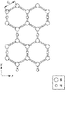
- FIG. 2 is a schematic diagram showing a local structure of a two-dimensional network composed of (BH) n (n ⁇ 4) according to the present embodiment.
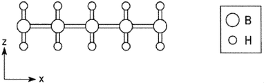
- FIG. 2 is a schematic diagram showing a local structure of a two-dimensional network composed of (BH) n (n ⁇ 4) according to the present embodiment.
- FIG. 2 is a schematic diagram showing a local structure of a two-dimensional network composed of (BH) n (n ⁇ 4) according to the present embodiment.
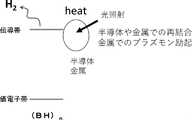
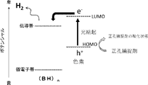
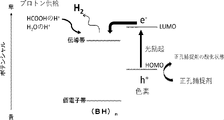
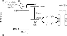
- Schematic diagram showing an example of the hydrogen release mechanism of the present composition by heat Schematic diagram showing an example of the hydrogen release mechanism of the present composition using a dye and a hole scavenger.
- TEM image of the composition of Example 8. Schematic explanatory drawing of the evaluation apparatus of the hydrogen gas release amount.
- the spectrum of the irradiation light used in the hydrogen gas release amount evaluation device. 2 is a graph plotting the amount of hydrogen gas released with respect to the visible light irradiation time of the compositions of Example 1 and the like.
- 4 is a graph showing results of visible light irradiation intensity and hydrogen gas release amount of the composition of Example 1.
- FIG. 4 is a graph plotting the amount of hydrogen gas released versus the visible light irradiation time of the compositions of Example 2 and the like.
- 4 is a graph plotting the amount of hydrogen gas released from the compositions of Examples 1 and 3 with respect to the visible light irradiation time.
- 4 is a graph plotting the amount of hydrogen gas released versus visible light irradiation time for the composition of Example 1 (effect of post-addition of dye and proton donor).
- 4 is a graph plotting the amount of hydrogen gas released against the visible light irradiation time of the composition of Example 4.
- FIG. The graph which plotted the amount of hydrogen gas emitted with respect to visible light irradiation time to compositions, such as Example 9, 10.
- FIG. A graph plotting the bandgap by Tauc-plot of the powdery products of Comparative Examples 4 and 5 and Reference Example 1.
- the borohydride-containing composition of the present embodiment is a boride that is a sheet material having a two-dimensional network consisting of (BH) n (n ⁇ 4, where n is an integer). It contains a hydrogen-containing sheet (hereinafter also referred to as a "borohydride-containing sheet") and an electron donor. At least a portion of the electron donor is supported on the surface of the borohydride-containing sheet. Electrons of the electron donor are supplied to the borohydride-containing sheet by an external stimulus, and hydrogen is generated from the borohydride-containing sheet into which the electrons have been injected.
- supporting includes a state of being chemically adsorbed on the surface of the borohydride-containing sheet or a state of being physically attached to the borohydride-containing sheet.
- the external stimulus may be any stimulus that can give a certain stimulus to the borohydride-containing composition to supply the electrons of the electron donor to the borohydride-containing sheet to generate hydrogen gas.
- Specific examples include energy beam irradiation such as heat, infrared rays, visible rays, ultraviolet rays, and electron beams.
- this composition since it contains an electron donor that induces hydrogen generation from the borohydride-containing sheet, hydrogen generation efficiency can be enhanced.
- the external stimulus can be selected according to needs and applications by selecting the type of electron donor.
- hydrogen can be released not only by ultraviolet rays, but also by sunlight and visible light, which is often found in white lighting.
- this embodiment can generate hydrogen at normal temperature and normal pressure, it does not exclude the combined use of a heating process and a pressurizing process. Each component will be described in detail below.
- borohydride-containing sheet refers to a sheet-like material having a two-dimensional network consisting of (BH) n (n ⁇ 4, where n is an integer).
- a two-dimensional network composed of (BH) n (n ⁇ 4) is formed at a molar ratio of 1:1 between boron atoms (B) and hydrogen atoms (H) (see Non-Patent Document 1).
- the borohydride-containing sheet may have a two-dimensional network consisting of (BH) n ( n ⁇ 4), and a compound ( For example, a compound in which a dopant is introduced into a part of a two-dimensional network consisting of (BH) n (n ⁇ 4), and a compound in which the end is blocked with an oxide, carbide, nitride, hydroxide, sulfide, etc. , a compound having an organic group attached to its end).
- the term "main skeleton" refers to a substance in which the borohydride-containing sheet accounts for 80% or more of the compound.
- Examples of the dopant include elements such as carbon, nitrogen, oxygen, fluorine, phosphorus, sulfur, chlorine, arsenic, selenium, bromine, antimony, tellurium, and iodine, titanium, vanadium, chromium, iron, cobalt, nickel, and copper. , zinc, cadmium, indium, tin, yttrium, niobium, molybdenum, tungsten, tantalum, lead, etc., and precious metal elements such as ruthenium, rhodium, palladium, silver, gold, iridium, platinum, etc. can be exemplified by at least one element.
- FIG. 1 to 3 show schematic diagrams of the local structure of a two-dimensional network consisting of (BH) n (n ⁇ 4).
- boron atoms are arranged in a hexagonal honeycomb shape (the hexagons formed by the boron atoms are connected to form a network), and among the boron atoms, adjacent two have the same hydrogen atom-bonding site.
- Boron atoms form a honeycomb sheet-like hexagonal lattice structure, and one hydrogen atom is a boron hexagonal lattice structure above and below the sheet, as shown in FIGS. It is bridged to two adjacent boron atoms among the atoms.
- two hydrogen atoms are arranged to face each other above and below the sheet-like hexagonal lattice structure. It should be noted that the arrangement of hydrogen in the borohydride does not have to have long-range order. Alternatively, a structure may be formed in which the bonds between atoms are inclined in the Z direction in FIGS. 2 and 3, or the sheet itself is bent. Also, not all hydrogen atoms are necessarily bonded on bridges.
- the borohydride-containing sheet is a thin film material, and may consist of a single layer or multiple layers.
- the total number of boron atoms (B) and hydrogen atoms (H) forming the network surface structure is 1000 or more.
- the bond distance d1 (see FIG. 1) between two adjacent boron atoms (B) is, for example, 0.155 nm to 0.190 nm.
- the bond distance d2 (see FIG. 2) between two adjacent boron atoms (B) via one hydrogen atom (H) is, for example, 0.155 nm to 0.190 nm.
- the bond distance d3 (see FIG. 2) between adjacent boron atoms (B) and hydrogen atoms (H) is, for example, 0.12 nm to 0.15 nm.
- the thickness of the borohydride-containing sheet is, for example, 0.2 nm to 10 nm.
- the length of the borohydride-containing sheet in at least one direction is preferably 100 nm or more. By setting the length in at least one direction to 100 nm or more, the borohydride-containing sheet can be used more effectively as electronic materials, catalyst support materials, catalyst materials, superconducting materials, and the like.
- the size (area) of the borohydride-containing sheet is not particularly limited, and can be formed to any size.
- the borohydride-containing sheet of this embodiment is a substance having a crystal structure. Moreover, according to the borohydride-containing sheet of the present embodiment, the bonding strength between the boron atoms (B) forming the hexagonal rings and between the boron atoms (B) and the hydrogen atoms (H) is strong. Therefore, even if the borohydride-containing sheet of the present embodiment forms a crystal (aggregate) in which a plurality of layers are laminated at the time of production, it can be easily cleaved along the crystal plane and single It can be separated (collected) as a two-dimensional sheet of layers.
- the borohydride-containing sheet is significantly lighter than the hydrogen storage alloy. Moreover, since it can be used under normal pressure, it is excellent in safety. It should be noted that this does not exclude use under conditions other than normal pressure.
- the method for producing the borohydride-containing sheet is not particularly limited.
- it can be produced by the following method. Specifically, first, a metal diboride having an MB2 type structure and an ion - exchange resin in which ions capable of ion exchange with metal ions constituting the metal diboride are coordinated are mixed in a polar organic solvent.
- M is at least one selected from the group consisting of Al, Mg, Ta, Zr, Re, Cr, Ti and V;
- This mixing step can be performed under an inert atmosphere comprising an inert gas such as nitrogen (N 2 ) or argon (Ar).
- metal diborides of MB 2 type structure those having a hexagonal ring structure are used.
- AlB2 aluminum diboride
- magnesium diboride (MgB2) tantalum diboride ( TaB2 ), zirconium diboride ( ZrB2), rhenium diboride ( ReB2 ), diboride Chromium (CrB 2 ), titanium diboride (TiB 2 ), vanadium diboride (VB 2 )
- It is preferable to use magnesium diboride because it can be easily ion-exchanged with an ion-exchange resin in a polar organic solvent.
- ion-exchange resin in which metal ions that constitute metal diboride and ions that can be ion-exchanged are coordinated.
- an ion exchange resin for example, a styrene polymer having a functional group (hereinafter referred to as "functional group ⁇ ") in which ions capable of ion exchange with metal ions constituting metal diboride are coordinated.
- a polymer of divinylbenzene having a functional group ⁇ and a copolymer of styrene having a functional group ⁇ and divinylbenzene having a functional group ⁇ .
- the functional group ⁇ include a sulfo group and a carboxy group. Among these, a sulfo group is preferable because it can easily exchange ions with the metal ions constituting the metal diboride in a polar organic solvent.
- the acid may be further added in the mixing process.
- acids include acetic acid, carbonic acid, tartaric acid, malic acid, maleic acid, propionic acid, formic acid, succinic acid, citric acid, oxalic acid, lactic acid, hydrochloric acid, sulfuric acid, and phosphoric acid.
- the polar organic solvent is not particularly limited, and examples include acetonitrile, N,N-dimethylformamide, and methanol.
- a method for removing the acid is not particularly limited, but examples thereof include heating, drying under reduced pressure, precipitation recovery method, and the like.
- filter the mixed solution For example, methods such as natural filtration, vacuum filtration, pressure filtration, and centrifugal filtration are used.
- the solution containing the product separated from the precipitate by filtration is dried naturally or dried under reduced pressure, by heating, etc., so that the borohydride-containing borohydride-containing solution having a two-dimensional network that is the final product get a sheet.
- Electrode donor refers to a substance capable of supplying electrons to a borohydride-containing sheet by an external stimulus and generating hydrogen from the electron-injected borohydride-containing sheet.
- the LUMO (lowest unoccupied molecular orbital) or conduction band level of the electron donor is less noble than the conduction band level of the borohydride-containing sheet.
- electron donors include light absorbers and heat absorbers. Specific examples of these include organic compounds.
- substances exhibiting metallic properties and substances exhibiting semiconductor properties can be exemplified.
- Examples of substances exhibiting metallic properties include metals, metal oxides, metal nitrides, metal carbides, metal oxynitrides, and metal oxycarbides.
- Examples of substances having semiconducting properties include semiconductors, metal nitrides, metal sulfides, and metal oxides. These are used singly or in any combination.
- suitable examples of organic compounds include dyes.
- the term “dye” refers to a compound that selectively absorbs visible light in a specific wavelength range, thereby causing color vision.
- a functional group may be introduced into the electron donor in order to increase the loading rate on the borohydride-containing sheet.
- Examples of such functional groups include a carboxy group, a phosphono group, and a sulfonic acid group. Among these, a carboxy group is preferred.
- FIG. 4 An example of the hydrogen generation mechanism of the present composition when a dye is used as an electron donor will be described with reference to FIG. However, the present invention is not limited to this mechanism.
- FIG. 4 an example using visible light as an external stimulus will be described. Visible light is absorbed by the dye, and this light absorption excites electrons of the dye from the HOMO (highest occupied molecular orbital) to the LUMO (lowest unoccupied molecular orbital). This creates holes (h + ) in the dye. Then, through the step of injecting the excited electrons into hydrogen ions in the conduction band level that constitute the antibonding orbitals of hydrogen in the borohydride-containing sheet, the reaction 2H + +2e ⁇ ⁇ H 2 ⁇ occurs. It is believed that hydrogen is generated and hydrogen is extracted.
- the present invention is not limited to this mechanism.
- an example using light irradiation as an external stimulus will be described.
- Light is absorbed by the semiconductor, and this light absorption excites electrons from the valence band of the semiconductor to the conduction band. It is believed that the excited electrons are injected into hydrogen ions at the conduction band level, which are the anti-bonding orbitals of hydrogen in the borohydride-containing sheet, and hydrogen is released.
- Heat may be used as an external stimulus instead of or in combination with light irradiation.
- the irradiation wavelength may be appropriately selected depending on the semiconductor used. Multiple semiconductors with different excitation wavelengths may be used together to utilize multiple irradiation wavelengths or bands.
- the present invention is not limited to this mechanism.
- an example using light irradiation as an external stimulus will be described.
- Light is absorbed by the metal, and this light absorption excites electrons from the HOMO of the metal to empty orbitals of the metal such as s or d orbitals. It is believed that the excited electrons are injected into hydrogen ions at the conduction band level, which are the anti-bonding orbitals of hydrogen in the borohydride-containing sheet, and hydrogen is released.
- Heat may be used as an external stimulus instead of or in combination with light irradiation.
- the irradiation wavelength may be appropriately selected according to the metal used. Multiple metals with different excitation wavelengths may be used together to utilize multiple irradiation wavelengths or bands.
- the dye is not particularly limited as long as it has a photosensitizing effect.
- Preferred examples include cis-di(thiocyanato)-bis(2,2′-bipyridyl-4,4′-dicarboxylic acid) ruthenium (II) (hereinafter also referred to as “N3”), cis-di(thiocyanato)-bis (2,2'-bipyridyl-4,4'-dicarboxylic acid) bis-TBA salt of ruthenium (II) (hereinafter also referred to as "N719"), cis-di(thiocyanato)-bis(2,2'-bipyridyl) -4,4'-dicarboxylic acid) tetra-TBA salt of ruthenium (II) (hereinafter also referred to as "N712”), tri(thiocyanato)-(4,4',4''-tricarboxy-2,2'
- coumarins polyenes, cyanines, hemicyanines, thiophenes, indolines, xanthenes, carbazoles, perylenes, porphyrins, phthalocyanines, merocyanines, catechols, azos, azines, and squaryliums.
- Various organic sensitizing dyes such as are also suitable.
- a donor-acceptor composite sensitizing dye or the like in which these sensitizing dyes are combined may be used.
- the dyes can be used singly or in combination of two or more.
- the dye preferably contains at least one of N3, N719, N712 and C106.
- a substance having metallic properties means a substance that has a metallic electronic structure and that can supply metal electrons to a borohydride-containing sheet by photosensitization or heat to excite the electrons of the metal.
- the type of which is not particularly limited.
- Preferred examples include gold, platinum, silver, copper, palladium, rhodium, ruthenium, rhenium, iridium, titanium, vanadium, chromium, manganese, iron, cobalt, nickel, zinc, zirconium, niobium, molybdenum, indium, tin, germanium,
- Examples include metals containing at least one selected from the group consisting of tantalum, tungsten, osmium, and lead, and alloys thereof.
- Metal carbides include TiC, ZrC, HfC, TaC, WC and the like. Since these exhibit metallic properties, they can be utilized as electron donors. Moreover, TiN, ZrN, HfN, TaN, WN etc. are mentioned as a metal nitride. These metal nitrides exhibit metallic properties and all function as electron donors. In addition, metal oxynitrides, metal oxycarbides, and compounds having metallic properties containing oxygen ions can also be used.
- a substance with semiconductor properties is a substance whose electrons are excited by light irradiation or heat, and the excited electrons can be supplied to the borohydride-containing sheet, and the type is not particularly limited. Suitable examples include tungsten oxide, bismuth oxide, iron oxide, nickel oxide, cobalt oxide, bismuth vanadate, oxides such as calcium iron ferrite, nitrides such as tantalum nitride, cadmium sulfide, zinc sulfide, indium sulfide, tin sulfide, Examples include semiconductors such as sulfides such as lead sulfide, selenides, tellurides, and phosphides.
- a semiconductor quantum dot with a diameter of about 5 to 20 nm is preferable from the viewpoint of control of electron injection efficiency and response wavelength.
- solvent The present composition can be used in the form of powder without using a solvent, but it may be dissolved or dispersed in a solvent.
- solvents include water and organic solvents.
- the organic solvent is not particularly limited, for example, amide-based solvents, alcohol-based solvents, ester-based solvents, ketone-based solvents, nitrile-based solvents, aromatic hydrocarbon-based solvents, halogenated hydrocarbons, ethers, amides, carbonate esters , hydrocarbons, nitromethane, and like solvents.
- nitrile solvents include acetonitrile, isobutyronitrile and propyronitrile
- examples of alcohol solvents include methanol, ethanol and propanol. Solvents may be used singly or in combination of two or more.
- the composition may further contain a hole trapping agent.
- the hole trapping agent traps holes generated in the electron donor by an external stimulus and becomes oxidized by itself, so that deterioration due to self-oxidation of the electron donor can be prevented.
- the redox potential of the hole trapping agent is preferably more negative than the HOMO (highest occupied molecular orbital) or valence band level of the electron donor.
- FIG. 8 shows a schematic diagram showing an example of the hydrogen generation mechanism when a hole trapping agent is used in the present composition.
- the present invention is not limited to this mechanism.
- Visible light is absorbed by the dye, and this light absorption excites electrons of the dye from the HOMO (highest occupied molecular orbital) to the LUMO (lowest unoccupied molecular orbital).
- holes (h + ) are generated in the dye, but the hole trapping agent supplies electrons to the dye, so that self-oxidation of the dye can be suppressed.
- This reaction oxidizes the hole scavenger and the dye continuously functions as an electron donor. By appropriately replenishing the hole scavenger, it is possible to increase the hydrogen generating power while suppressing the amount of dye added.
- the hole trapping agent is not particularly limited as long as it has the above functions.
- Preferable examples include triethanolamine (TEOA), ascorbic acid; 1-benzyl-1,4-dihydronicotinamide; benzimidazole derivatives; alcohols such as methanol, ethanol, butanol and propyl alcohol; aldehydes such as formaldehyde and acetaldehyde Carboxylic acids such as formic acid, acetic acid, and propionic acid; Bromine ions, iodine ions, iodate ions, iron ions (Fe 2+ ), redox reagents such as ferrocene, photocatalyst-activated ethylenediaminetetraacetic acid (EDTA); Sodium formate, polysulfide ions is mentioned.
- TEOA triethanolamine
- ascorbic acid 1-benzyl-1,4-dihydronicotinamide
- benzimidazole derivatives benzimid
- the hole trapping agent may be reused by reducing the oxidation state in which holes are trapped.
- a method for reducing the hole scavenger a method of mixing a chemical reducing agent such as sodium borohydride, hydrazine, or aldehydes into the present composition can be exemplified.
- the hole trapping agent can be electrochemically reduced by contacting the present composition with a cathode electrode (not shown) instead of or in combination with the above method.
- the composition may further contain a proton donor.
- a proton donor is a compound that can donate as a proton, and may be one that can be dissolved in a liquid or one that can be dispersed without being dissolved in a liquid.
- Preferable examples of proton donors include inorganic acids, carboxylic acids, organic acids such as sulfonic acids and phenols, alcohols, mercaptans, and 1,3-dicarbonyl compounds.
- solid acids such as zeolites and ion exchange resins are also suitable.
- Suitable examples of proton donors include acids such as formic acid.
- FIG. 9 shows a schematic diagram showing an example of the hydrogen generation mechanism when a proton donor is used in this composition.
- An example of the mechanism of hydrogen generation will be described with reference to the figure.
- the present invention is not limited to this mechanism.
- a proton donor is used in addition to the borohydride-containing sheet as the hydrogen source. This provides a source of hydrogen depleted of borohydrides to enhance hydrogen release.
- the composition may contain high-molecular-weight compounds or low-molecular-weight compounds such as binder resins and dispersants within the scope of the present invention.
- additives such as antistatic agents, thermally conductive fillers, and flame retardants can be added as appropriate.
- composition containing borohydride The composition can be used as a powder. Alternatively, a solvent may be added to form a solution, dispersion, or slurry. Also, the present composition may be formed into a film-like form or a molded article of any shape. The film or molded body can also be a porous body. A laminate in which a film containing a borohydride-containing sheet and an electron donor supported thereon is laminated with a hole scavenger layer on one main surface thereof and a proton donor layer on the other main surface thereof may also be used. good.
- the method for producing the borohydride-containing composition is not particularly limited. It can be obtained by mixing the raw materials of the composition in any order. In addition to adjusting the composition in advance, it may be prepared by adding the components of the composition at the timing of use.
- FIG. 10 illustrates an example of a method for electrochemically reducing a hole trapping agent.
- a dye is used, and visible light is used as an external stimulus to release hydrogen. do.
- the hole trapping agent is electrochemically reduced, and the hole trapping agent can be continuously reused.
- hydrogen release from the borohydride-containing sheet can be supplemented by adding a proton donor.
- the hydrogen generation system utilizes the borohydride-containing composition described above, and the borohydride-containing composition and the control for controlling the on/off of the external stimulus to this borohydride-containing composition and a hydrogen generation unit for extracting hydrogen to the outside.
- This hydrogen generation system can be applied to general applications in which hydrogen is generated by external stimulation such as light irradiation.
- An example of a specific embodiment of the hydrogen generation system will be described below. Each embodiment can be suitably combined.
- FIG. 11 shows a schematic explanatory view of the hydrogen generation system according to the first embodiment.
- the hydrogen generation system 1 has a hydrogen generation section 10 and an external stimulation control section 20 .
- a raw material supply tank 11, a solvent supply channel 12, a gas recovery channel 13, and a discharge channel 14 are connected to the hydrogen generation unit 10.
- a container containing a borohydride-containing composition 30 and a stirring unit 15 for stirring the container are connected to the hydrogen generation unit 10.
- the borohydride-containing composition other than the solvent is supplied from the raw material supply tank 11 .
- a borohydride-containing composition containing a solvent may be supplied from a raw material supply tank.
- the borohydride-containing sheet, the electron donor, and optionally the hole trapping agent and proton donor may be supplied separately or in any combination.
- a tank for supplying an electron donor carried on a borohydride-containing sheet, a tank for supplying a hole scavenger, and a tank for supplying a proton donor may be provided. By doing so, it is possible to design so as to supply the optimum material according to the conditions of use.
- the external stimulus control section 20 plays a role of supplying an external stimulus at a desired timing to the borohydride-containing sheet 31 carrying the electron donor dispersed in the solvent 32 in the hydrogen generating section 10 .
- an external stimulus when visible light is used as an external stimulus, it has a visible light irradiation function and a function of controlling on/off of visible light irradiation. That is, it has a visible light source and an irradiation control function for this light source. External light such as sunlight may be used instead of incorporating a light source.
- the external stimulation control section 20 has a function of controlling transmission/blocking of external light.
- the hydrogen generated in the hydrogen generator 10 is collected through the gas recovery passage 13.
- the amount of hydrogen is controlled by controlling the conditions of the external stimulation (intensity, time, etc.) and the conditions of the borohydride-containing composition (amount, concentration, shape, etc.). Easy to adjust. Therefore, it is possible to supply hydrogen by light irradiation without previously storing hydrogen gas in a storage tank. Of course, it is not excluded to store hydrogen in the hydrogen storage tank via the gas recovery path 13 . When such a hydrogen storage tank is provided, there is an advantage that a desired amount of hydrogen can be taken out instantaneously.
- the hydrogen generating unit 10 is not provided with a container for containing the present composition 30 and the stirring unit 15, but is provided with a flow path (not shown), and the present composition 30 is flowed through this flow path at a desired flow rate.
- a configuration in which hydrogen is generated by supplying an external stimulus may be employed.
- a high-pressure tank is not required, and hydrogen can be easily generated at normal temperature and normal pressure. Moreover, since hydrogen generation can be controlled by light irradiation, on/off control of hydrogen generation can be instantaneously and easily performed as compared with the heating method. In addition, the mass can be significantly reduced compared to hydrogen storage alloys.
- the hydrogen generation system according to the second embodiment differs from the first embodiment in that gas is used as a dispersion medium and that the composition does not contain a solvent.
- Element members having the same functions as those described above are denoted by the same reference numerals in subsequent drawings. Also, the description overlapping with that of the first embodiment will be omitted as appropriate.
- FIG. 12 shows a schematic explanatory diagram of the hydrogen generation system according to the second embodiment.
- the hydrogen generation system 2 has a hydrogen generation section 10 and an external stimulation control section 20 .
- a raw material supply tank 11 , a gas recovery path 13 , a discharge path 14 , a gas supply path 16 and the like are connected to the hydrogen generating section 10 .
- the hydrogen generating section 10 has an air flow generating section 17 for causing the present composition to dance and diffuse in the gas.
- the hydrogen generating unit 10 is configured to be supplied with the borohydride-containing composition 30 through the raw material supply tank 11 and nitrogen gas or inert gas through the gas supply path 16 at desired timings. .
- the airflow generating part 17 plays a role of causing the borohydride-containing composition 30 dispersed in the gas, which is the dispersion medium, to dance within the hydrogen generating part 10 .
- the external stimulus control unit 20 plays a role of supplying an external stimulus at a desired timing to the borohydride-containing composition 30 dispersed in the airflow.
- the configuration can be similar to that of the first embodiment.
- the hydrogen generated in the hydrogen generator 10 is collected through the gas recovery passage 13. It is configured to recover gas containing a large amount of hydrogen gas by upward displacement.
- the hydrogen generation system according to the second embodiment by controlling the conditions of the external stimulation (intensity, time, etc.) and the conditions of the present composition (amount, shape, type of electron donor, supported amount, etc.), The amount of hydrogen generated at normal temperature and pressure can be adjusted.
- the residue-containing gas is discharged from the discharge passage 14 at an appropriate timing.
- the recovered residue can be separated into a gas and a residue by a filter, and each can be reused.
- the hydrogen generation unit 10 is made of a thin container, and the thin container in which the light source, which is the external stimulus control unit, is built in the hydrogen generation unit 10 is used. differ from
- FIG. 13 shows a schematic explanatory diagram of the main part of the hydrogen generation system according to the third embodiment.
- the hydrogen generator 10 has a plurality of thin containers 18 .
- An LED light source 21 serving as an external stimulus controller is built in the thin container 18 .
- the hydrogen generation unit 10 includes a supply channel (not shown) for supplying a dispersion medium (present composition) in which the borohydride-containing sheet supporting an electron donor is dispersed, a gas recovery channel (not shown), and a dispersion medium.
- a discharge path (not shown) and the like are connected.
- the dispersion medium may be liquid or gas.
- the thin container 18 is configured to be supplied with the dispersion medium in which the borohydride-containing sheet is dispersed from the supply channel at a desired timing.
- the borohydride-containing composition 30 dispersed in the hydrogen generating part 10 is irradiated with light from the LED light source 21 at the timing at which hydrogen is desired to be generated.
- the hydrogen generated in the thin container 18 is collected through the gas recovery path.
- effects similar to those of the first embodiment can be obtained.
- by using a plurality of thin containers 18 together it is possible to generate hydrogen gas according to needs.
- the hydrogen generation system according to the fourth embodiment differs from the above-described embodiments in that the present composition is supported on a support.
- FIG. 14 shows an example of a schematic explanatory diagram of the essential parts of the hydrogen generation system according to the fourth embodiment.
- a powdery borohydride-containing composition 30 is supported on beads 41 that are transparent to the light to be irradiated.
- the supported beads 40 in which the borohydride-containing composition 30 is supported on the beads 41 it is possible to increase the area of the present composition that receives an external stimulus, thereby enhancing the hydrogen release efficiency.
- the hydrogen generating unit 10 has a transport belt 19 that transports the supported beads 40 at a desired speed. It is designed to be The hydrogen generated in the hydrogen generating section 10 is collected through the gas recovery passage 13 . The light irradiation conditions, the transfer speed of the transfer belt 19, and the transfer amount of the support beads 40 are adjusted so that the amount of hydrogen released from the support beads 40 on the transfer belt 19 is not reduced.
- the hydrogen generation system according to the fifth embodiment differs from the previous embodiments in that the powder of the present composition is dispersed in a binder.
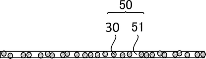
- FIG. 15 shows a schematic explanatory view of the film used in the hydrogen generation system according to the fifth embodiment.
- the film 50 consists of a compact in which powder of the borohydride-containing composition 30 is dispersed in a binder 51 .
- a binder 51 Such a molded body may be formed on a support. Dispersing the borohydride-containing composition 30 in the binder 51 facilitates molding into a desired shape.
- the binder 51 is preferably an expandable resin or a porous body so as not to hinder hydrogen generation.
- the binder is preferably made of a material that is highly transparent to the light so as not to lower the hydrogen release efficiency.
- the fuel cell system according to the present embodiment is obtained by mounting the above-described hydrogen generation system as a hydrogen supply source on a known fuel cell. According to the fuel cell according to this embodiment, hydrogen can be easily supplied to the fuel cell even at room temperature without using a high-pressure tank.
- Synthesis example 1 Based on Non-Patent Document 1, a borohydride-containing sheet having a two-dimensional network consisting of (BH) n (n ⁇ 4) was synthesized. Specifically, 500 mg of magnesium diboride (manufactured by Sigma-Aldrich) and 30 mL of a cation exchange resin (manufactured by Organo) were stirred in acetonitrile at room temperature for 3 days. This solution was filtered through a filter with a pore size of 0.2 ⁇ m, and the filtrate was dried under reduced pressure at 80° C. to obtain a yellow product.
- magnesium diboride manufactured by Sigma-Aldrich
- a cation exchange resin manufactured by Organo
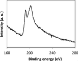
- FIG. 17 A transmission electron micrograph of the product obtained in Synthesis Example 1 is shown in FIG. As shown in the figure, it was confirmed to be a sheet-like substance. Further, the result of electron energy loss spectroscopy (EELS) of this product is as shown in FIG. 17, and a split peak of 193 eV and 202 eV was confirmed. The former is attributed to the transition from the 1s orbital to the ⁇ * orbital of boron, and the latter is attributed to the transition from the 1s orbital to the ⁇ * orbital, indicating that boron is a network of two-dimensional sp hybridized orbitals.
- FIG. 18 shows the infrared spectrum (FT-IR) of the product. As shown in the figure, BH vibration and BHB vibration were observed at 2500 cm ⁇ 1 and 1400 cm ⁇ 1 , respectively, confirming that the borohydride-containing sheet has a two-dimensional network.
- FT-IR infrared spectrum
- Example 1 2.8 mg of the borohydride-containing sheet obtained in Synthesis Example 1, the N3 dye (cis-bis(isothiocyanato)bis(2,2'-bipyridyl-4,4'-dicarboxylate) represented by the chemical formula (1) )
- a borohydride-containing composition according to Example 1 was obtained in which 0.2 mg of ruthenium (II)) was dispersed in 5 mL of acetonitrile.
- FIG. 19 shows the UV-Vis spectrum of the obtained composition.
- the figure also shows the UV-Vis spectrum of Comparative Example 1, which will be described later.
- the composition of Example 1 has absorption in a wide range of visible light.
- Example 2 (Example 2) 2.8 mg of the borohydride-containing sheet obtained in Synthesis Example 1 and 0.2 mg of N3 dye were mixed to obtain a powdery composition according to Example 2.
- Example 3 A composition according to Example 3 was obtained by dispersing 2.8 mg of the borohydride-containing sheet obtained in Synthesis Example 1, 0.2 mg of N3 dye, and 2 mL of TEOA (triethanolamine) as a hole scavenger in 3 mL of acetonitrile. rice field.
- TEOA triethanolamine
- Example 4 An acetonitrile dispersion (0.05 mol/L) of the borohydride-containing sheet and an acetonitrile dispersion (0.000065 mol/L) of AuCl 3 (manufactured by Fuji Film Co., Ltd.) were mixed.
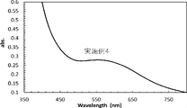
- FIG. 20 shows the UV-Vis spectrum one hour after mixing. As shown in the figure, the composition of Example 4 has absorption in a wide range of visible light.
- Example 5 By vacuum-drying the composition according to Example 4, a powdery composition according to Example 5 was obtained. In the total composition according to Example 5, the charged amount of gold was 2.7% by mass. A TEM image of the obtained powder is shown in FIG. As shown in FIG. 21, it can be seen that gold is supported on the borohydride-containing sheet.
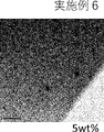
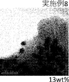
- Examples 6-8) Compositions according to Examples 6 to 8 were obtained in the same manner as in Examples 4 and 5, except that the amount of gold charged in the entire composition was changed to 5, 10 and 13% by mass in that order.
- TEM images of the powdery compositions of Examples 6-8 are shown in FIGS. 22-24, respectively. Gold was confirmed to be supported on the borohydride-containing sheet for all compositions.
- Example 9 The composition of Example 1 was vacuum dried to obtain Example 9 in powder form. Further, the composition synthesized by substituting 4-4′ bipyrdyl for N3 for the dye of Example 1 was vacuum-dried to obtain Example 10 in the form of powder.
- Comparative example 1 A composition according to Comparative Example 1 was obtained by dispersing 2.8 mg of the borohydride-containing sheet obtained in Synthesis Example 1 in 5 mL of acetonitrile.
- Comparative example 2 A composition according to Comparative Example 2 was obtained in which 0.2 mg of N3 dye was dispersed in 5 mL of acetonitrile.
- Reference Example 1 The powder of the borohydride-containing sheet obtained in Synthesis Example 1 is referred to as Reference Example 1.
- Comparative Example 4 A product of Comparative Example 4 was obtained in the same manner as in Comparative Example 3, except that the value of x was changed to 0.04.
- the hydrogen release amount of the composition obtained in Example 1 was evaluated by the following method. That is, 5 mL of the composition obtained in Example 1 was placed in a closed quartz glass container 60, and as shown in FIG. . The inside of the quartz glass container 60 was made into a nitrogen atmosphere, and the amount of hydrogen gas released was measured by analyzing the gas inside the container with a micro GC. The distance between the lower surface of the measurement sample 63 and the visible light source was set to 2 cm.
- the measurement sample 63 was allowed to stand in a dark room for 2 hours, and then the hydrogen release amount when irradiated with visible light was measured by a gas chromatograph GC-2010 Plus (manufactured by Shimadzu Corporation) equipped with a barrier discharge ionization detector (not shown). .
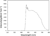
- a visible light source super bright 500 XEF-501S (manufactured by Tokina, 500 W, 25.0 A) was used, and light of 470 nm or less was cut by a cut filter 61 .
- FIG. 26 shows the spectrum of the irradiated light.
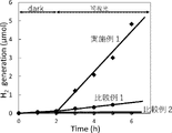
- FIG. 27 shows a plot of the amount of hydrogen released with respect to visible light non-irradiation (Dark) and visible light irradiation time for Example 1 and Comparative Examples 1 and 2.
- substantially no hydrogen was generated in any of the samples when not irradiated, and the composition of Example 1 released a significantly higher amount of hydrogen than Comparative Example 1 when exposed to visible light. It was confirmed.
- the internal quantum efficiency for the amount of hydrogen released in Example 1 was 4.42%. The internal quantum efficiency was obtained by calculating the number of absorbed photons from the absorption spectrum of the composition and the spectrum of the light source, and dividing the number by the number of electrons required for hydrogen generation, which is a two-electron reaction.
- Example 5 Using the apparatus shown in FIG. 25, the hydrogen release amount of the composition of Example 3 was measured. Specifically, a 5 mL sample was placed in a quartz glass container 60, and the distance between the quartz glass container 60 in contact with the sample and the xenon light source 62 (super bright 500 XEF-501S (manufactured by Tokina), 500 W, 25.0 A) was The position of the light source was adjusted so that the distance was 2 cm. Also, a cut filter 61 was used to cut light of 470 nm or less. The results and the results of Example 1 obtained in Evaluation 1 are shown in FIG. As shown in the figure, it was confirmed that the addition of the hole trapping agent increased the amount of hydrogen released.
- the xenon light source 62 super bright 500 XEF-501S (manufactured by Tokina), 500 W, 25.0 A
Landscapes
- Chemical & Material Sciences (AREA)
- Organic Chemistry (AREA)
- Engineering & Computer Science (AREA)
- Inorganic Chemistry (AREA)
- Chemical Kinetics & Catalysis (AREA)
- General Health & Medical Sciences (AREA)
- Combustion & Propulsion (AREA)
- Health & Medical Sciences (AREA)
- Life Sciences & Earth Sciences (AREA)
- Manufacturing & Machinery (AREA)
- Sustainable Development (AREA)
- Sustainable Energy (AREA)
- Electrochemistry (AREA)
- General Chemical & Material Sciences (AREA)
- Fuel Cell (AREA)
Abstract
Description
本発明は上記背景に鑑みてなされたものであり、ホウ化水素含有シートを用いた水素供給源の更なる性能向上、水素生成の省エネルギー化を実現するホウ化水素含有組成物、水素発生システムおよび燃料電池システムを提供することを目的とする。
[1]: (BH)n(n≧4、但しnは整数)からなる二次元ネットワークを有するホウ化水素含有シートと、電子供与体とを含有し、
前記電子供与体の少なくとも一部が、前記ホウ化水素含有シートの表面に担持され、
外部刺激により、前記電子供与体の電子が前記ホウ化水素含有シートに供給され、当該電子が注入された前記ホウ化水素含有シートから水素が発生するホウ化水素含有組成物。
[2]: 前記電子供与体のLUMO(最低空軌道)または伝導帯準位が前記ホウ化水素含有シートの伝導帯準位より卑であることを特徴とする[1]記載のホウ化水素含有組成物。
[3]: 前記電子供与体は可視光線により励起され、前記励起された電子を前記ホウ化水素含有シートに供給することにより前記ホウ化水素含有シートから水素が発生する[1]または[2]記載のホウ化水素含有組成物。
[4]: 前記電子供与体は、有機化合物であることを特徴とする[1]~[3]のいずれかに記載のホウ化水素含有組成物。
[5]: 前記電子供与体は、カルボキシ基、ホスホノ基およびスルホン酸基の少なくともいずれかを有していることを特徴とする[1]~[4]のいずれかに記載のホウ化水素含有組成物。
[6]: 溶媒を含有することを特徴とする[1]~[5]のいずれかに記載のホウ化水素含有組成物。
[7]: 更に、正孔捕捉剤が含有されている[1]~[6]のいずれかに記載のホウ化水素含有組成物。
[8]: 前記正孔捕捉剤の酸化還元電位が、前記電子供与体のHOMO(最高被占軌道)または価電子帯準位よりも卑であることを特徴とする[7]に記載のホウ化水素含有組成物。
[9]: 更に、プロトン供与体を含むことを特徴とする[1]~[8]のいずれかに記載のホウ化水素含有組成物。
[10]: 前記プロトン供与体が酸であることを特徴とする[9]記載のホウ化水素含有組成物。
[11]: [1]~[10]のいずれかに記載のホウ化水素含有組成物を含む水素発生システムであって、
ホウ化水素含有組成物と、
前記ホウ化水素含有組成物への外部刺激のオンオフを制御する制御部と、
外部に水素を取り出す水素発生部とを備える水素発生システム。
[12]: [11]に記載の水素発生システム、および前記水素発生システムから水素が供給される燃料電池を備える燃料電池システム。
本明細書において「ホウ化水素含有シート」とは、(BH)n(n≧4、但しnは整数)からなる二次元ネットワークを有しているシート状物質をいう。(BH)n(n≧4)からなる二次元ネットワークは、ホウ素原子(B)と水素原子(H)がモル比で1:1の割合で形成される(非特許文献1参照)。
本明細書において「電子供与体」とは、前述したように、外部刺激により、ホウ化水素含有シートに電子を供給し、当該電子が注入されたホウ化水素含有シートから水素が発生し得る物質をいう。電子供与体のLUMO(最低空軌道)または伝導帯準位が前記ホウ化水素含有シートの伝導帯準位より卑であることが好ましい。電子供与体の具体例として、光吸収体、熱吸収体が例示できる。これらの具体例として、有機化合物が例示できる。また、金属的性質を示す物質、半導体的性質を示す物質が例示できる。金属的性質を示す物質として、金属、金属酸化物、金属窒化物、金属炭化物、金属酸窒化物、金属酸炭化物が例示できる。また、半導体的性質を持つ物質として、半導体、金属窒化物、金属硫化物、金属酸化物が例示できる。これらは単独もしくは任意に組み合わせて用いられる。外部刺激として可視光を用いる場合、有機化合物の好適例として色素が挙げられる。ここで色素とは、特定波長域の可視光を選択的に吸収し、これにより色覚をおこさせる化合物をいう。
本組成物は、溶媒を用いずに粉体で用いることもできるが、溶媒に溶解または分散されていてもよい。溶媒は、水または有機溶媒が例示できる。有機溶媒は特に限定されないが、例えば、アミド系溶剤、アルコール系溶剤、エステル系溶剤、ケトン系溶剤、ニトリル系溶剤、芳香族炭化水素系溶剤、ハロゲン化炭化水素、エーテル類、アミド類、炭酸エステル類、炭化水素、ニトロメタンなどの溶媒が挙げられる。ニトリル系溶剤としてはアセトニトリル、イソブチロニトリル、プロピロニトリルが、アルコール系溶剤としてはメタノール、エタノール、プロパノール等が例示できる。溶媒は一種単独または二種以上を併用して用いられる。
本組成物は、更に、正孔捕捉剤を含有していてもよい。正孔捕捉剤は、外部刺激により電子供与体に生じた正孔をトラップし、自らが酸化状態になるため、電子供与体の自己酸化による劣化を防ぐことができる。正孔捕捉剤の酸化還元電位は、電子供与体のHOMO(最高被占軌道)または価電子帯準位よりも卑であることが好ましい。
本組成物は、更にプロトン供与体を含有していてもよい。プロトン供与体とは、プロトンとして供与できる化合物のことをいい、液体に溶解できるものでも、溶解せずに分散するものでもよい。プロトン供与体としては、好適例として無機酸、カルボン酸、スルホン酸およびフェノール類などの有機酸、アルコール類、メルカプタン類、1,3-ジカルボニル化合物が挙げられる。更に、ゼオライト、イオン交換樹脂などの固体酸も好適である。プロトン供与体の好適例としてギ酸などの酸が例示できる。
本組成物は、本発明の趣旨を逸脱しない範囲内においてバインダー樹脂、分散剤などの高分子化合物または低分子化合物を添加することができる。また、帯電防止剤、熱導電性フィラー、難燃剤などの添加剤を適宜添加できる。
本組成物は、粉体として用いることができる。また、溶媒を加えて溶液、分散液、スラリーとして用いてもよい。また、本組成物をフィルム状や任意の形状の成形体としてもよい。フィルムや成形体は、多孔質体とすることもできる。ホウ化水素含有シートと、これに担持された電子供与体を含有するフィルムの一主面上に正孔捕捉剤層を、他主面上にプロトン供与体層を積層した積層体を用いてもよい。
ホウ化水素含有組成物の製造方法は特に限定されない。組成物の原料を任意の順に混合することにより得ることができる。予め組成物を調整しておく他、使用するタイミングで組成物の成分を投入して調製してもよい。
本組成物に、再生可能な正孔捕捉剤とプロトン供与体を含有させることによって、外部刺激によってホウ化水素含有シートと電子供与体の劣化を防ぎ、持続的に水素を生成することができる。即ち、ホウ化水素含有シートからの水素が放出された後でもプロトン供与体から水素源が供給される。また、電子供与体の電子・正孔対はそれぞれホウ化水素含有シートと正孔捕捉剤に移動し、電子供与体自体の自己酸化や自己還元による劣化を抑制できる。
本実施形態に係る水素発生システムは、上述したホウ化水素含有組成物を利用したものであり、ホウ化水素含有組成物と、このホウ化水素含有組成物への外部刺激のオンオフを制御する制御部と、外部に水素を取り出す水素発生部とを備える。この水素発生システムは、光照射などの外部刺激によって水素を発生させたい用途全般に適用できる。以下、水素発生システムの具体的な実施形態の一例について説明する。各実施形態は好適に組み合わせられる。
図11に、第1実施形態に係る水素発生システムの模式的説明図を示す。水素発生システム1は、水素発生部10、外部刺激制御部20を有する。水素発生部10には、原料供給タンク11,溶媒供給路12,ガス回収路13、排出路14が接続されており、ホウ化水素含有組成物30を収容する容器およびこれを撹拌する撹拌部15を有する。図11の例では原料供給タンク11から、ホウ化水素含有組成物のうち溶媒以外の組成物が供給される。溶媒を含めたホウ化水素含有組成物を原料供給タンクから供給してもよい。また、ホウ化水素含有シート、電子供与体、および必要に応じて正孔捕捉剤およびプロトン供与体を別々に供給したり、任意に組み合わせて供給したりしてもよい。例えば、ホウ化水素含有シートに担持された電子供与体を供給するタンク、正孔捕捉剤を供給するタンク、プロトン供与体を供給するタンクをそれぞれ設けてもよい。このようにすることにより、使用状況に応じて、最適な材料を供給するように設計することができる。
次に第1実施形態とは異なる水素発生システムの例について説明する。第2実施形態に係る水素発生システムは、分散媒として気体を用いる点および組成物に溶媒を含まない点において第1実施形態と相違する。なお、以降の図において前出と同様の機能を有する要素部材は同一符号を付す。また、第1実施形態と重複する記載は適宜省略する。
第3実施形態に係る水素発生システムは、水素発生部10が薄型容器からなり、外部刺激制御部である光源が水素発生部10内に内蔵された薄型容器を用いる点において、前述までの実施形態と相違する。
第4実施形態に係る水素発生システムは、担持体に本組成物を担持させている点において、前述までの実施形態と相違する。
第5実施形態に係る水素発生システムは、本組成物の粉体をバインダー中に分散させている点において、前述までの実施形態と相違する。
本実施形態に係る燃料電池システムは、公知の燃料電池に対し、水素供給源として上述した水素発生システムを搭載したものである。本実施形態に係る燃料電池によれば、高圧タンクを用いずに、常温でも簡便に燃料電池に水素を供給することができる。
非特許文献1に基づき、(BH)n(n≧4)からなる二次元ネットワークを有するホウ化水素含有シートの合成を行った。具体的には、アセトニトリル中で、二ホウ化マグネシウム(シグマ・アルドリッチ社製)500mgと陽イオン交換樹脂(オルガノ社製)30mLを室温のもと3日間撹拌を行った。この溶液を孔径0.2μmのフィルターで濾過し、濾液を80℃下で減圧乾燥させることにより、黄色に呈した生成物を得た。
合成例1で得たホウ化水素含有シート2.8mg、化学式(1)で示されるN3色素(cis-ビス(イソチオシアナート)ビス(2,2’-ビピリジル-4,4’-ジカルボキシラート)ルテニウム(II))0.2mgをアセトニトリル5mLに分散させた実施例1に係るホウ化水素含有組成物を得た。

合成例1で得たホウ化水素含有シート2.8mgとN3色素0.2mgを混合し、粉末状の実施例2に係る組成物を得た。
合成例1で得たホウ化水素含有シート2.8mg、N3色素0.2mg、正孔捕捉剤としてTEOA(トリエタノールアミン)2mLをアセトニトリル3mL中で分散させた実施例3に係る組成物を得た。
ホウ化水素含有シートのアセトニトリル分散液(0.05mol/L)と、AuCl3(富士フィルム社製)のアセトニトリル分散液(0.000065mol/L)とを混合した。混合してから1時間後のUV-Visスペクトルを図20に示す。同図に示すように、実施例4の組成物は幅広い可視光域の吸収を有する。
実施例4に係る組成物を真空乾燥することにより、粉末状の実施例5に係る組成物を得た。実施例5に係る全組成物中、金の仕込み量は2.7質量%である。得られた粉体のTEM像を図21に示す。図21に示すように、ホウ化水素含有シートに金が担持されていることがわかる。
全組成物中、金の仕込み量を順に5、10、13質量%に変更した以外は、実施例4,5と同様の方法により実施例6~8に係る組成物を得た。粉体状の実施例6~8の組成物のTEM像を順に図22~24に示す。いずれの組成物も、ホウ化水素含有シートに金が担持されていることを確認した。
実施例1の組成物を真空乾燥して、粉末状の実施例9を得た。また、実施例1の色素をN3から4-4‘ビピルジルに置き換えて合成した組成物を真空乾燥して粉末状の実施例10を得た。
合成例1で得たホウ化水素含有シート2.8mgをアセトニトリル5mLに分散させた比較例1に係る組成物を得た。
N3色素0.2mgをアセトニトリル5mLに分散させた比較例2に係る組成物を得た。
合成例1で得たホウ化水素含有シートの粉末を参考例1とする。
マグネシウム(Mg)粉末、ホウ素(B)粉末、グラファイト(C)粉末が、Mg:B:Cのモル比が1:2-2x:2x(xは任意)の比になるように混合し、不活性雰囲気下、A. Yamamoto, et al. Supercond. Sci. Technol. 17, 921, 2004.に記載のPowder-in-closed-tube法により900℃、48時間焼成してMgB2の結晶格子内に炭素をドープした粉末を得た。比較例3では、xの値が0.02、即ち、炭素のドープ量が2%のMgB2粉末を合成した。
次いで、炭素のドープ量が2%のMgB2粉末500mgを合成例1と同様に、アセトニトリル中で陽イオン交換樹脂(オルガノ社製)30mLと混合し、室温のもと3日間撹拌を行った。この溶液を孔径0.2μmのフィルターで濾過し、濾液を80℃下で減圧乾燥させることにより、生成物を得た。
比較例3において、xの値を0.04に変更したこと以外は比較例3と同様の方法により比較例4の生成物を得た。
実施例1で得た組成物に対して、以下の方法により水素放出量を評価した。即ち、実施例1で得た組成物5mLを閉鎖型の石英ガラス容器60に入れ、図25に示すように、石英ガラス板越しに測定試料63に可視光が照射されるように光源を設置した。石英ガラス容器60内は窒素雰囲気とし、容器内の気体をマイクロGCにより分析することにより水素ガス放出量を測定した。測定試料63下面と可視光源の距離は2cmとした。測定試料63を暗室にて2時間静置し、次いで可視光を照射したときの水素放出量を、バリア放電イオン化検出器を搭載した不図示のガスクロマトグラフGC-2010Plus(島津社製)により測定した。可視光源として、super bright 500 XEF-501S(Tokina社製、500W、25.0A)を用い、カットフィルター61により470nm以下の光をカットした。図26に、照射光のスペクトルを示す。
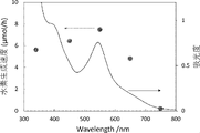
実施例1の組成物について、光源を単色光源とした点以外は評価1と同様の方法により光照射1時間あたりの水素生成速度を測定した。単色光源については評価1に記載の可視光源super bright 500 XEF-501S(Tokina社製、500W、25.0A)を用い、各種バンドパスフィルター(波長:757,650,550,450,340nm)を介してサンプルに照射した。それらの結果(アクションスペクトル)と実施例1の組成物のUV-Vis吸収スペクトルを重ねた結果を図28に示す。同図に示すように、アクションスペクトルと吸収スペクトルが一致したことから、水素生成が実施例1の組成物の光励起によって誘起されていることが示された。
実施例1の組成物について、光源とサンプルの距離を経時的に変更した点に加え、実施例1で得た組成物のうちから3mLを使用した点以外は評価1と同様の方法により水素放出量を測定した。その結果を図29に示す。同図に示すように、光源との照射距離、即ち、光強度により水素放出量が変わることを確認した。
図25に示す装置を用いて、粉末状である実施例2の組成物の水素放出量を測定した。その結果を図30に示す。同図に示すように、粉末系でも水素放出することを確認した。
図25に示す装置を用いて、実施例3の組成物の水素放出量を測定した。具体的には、石英ガラス容器60に5mLの試料を入れ、その試料と接する石英ガラス容器60とキセノン光源62(super bright 500 XEF-501S(Tokina社製)、500W、25.0A)との距離が2cmとなるように光源の位置を調整した。また、カットフィルター61を用いて470nm以下の光をカットした。その結果、並びに評価1で得た実施例1の結果を図31に示す。同図に示すように、正孔捕捉剤の添加により水素放出量増加が確認された。
実施例1の組成物について、以下の操作を行った以外は評価1と同様にして水素放出量を測定した。具体的には、本評価5においては、可視光照射後90時間後に光照射をやめ、且つ色素であるN3を1mg添加した。次いで、非照射時間が5時間経過したところで、再び可視光照射を45.5時間行ったところで光照射をやめ、且つプロトン供与体であるギ酸を1mL添加した。次いで、非照射時間が7.5時間経過したところで、再び可視光照射を行った。このときの水素放出量を図32に示す。同図に示すように、N3を添加しても水素放出量の増加は認められなかった一方で、ギ酸の添加によって水素放出量の増加が認められた。照射100時間程度での水素放出量の飽和は、色素分解に起因するものではなく、ホウ化水素含有シートの水素が放出されたためであって、プロトン供与体を添加することでホウ化水素含有シートから持続的に水素を発生させることができることを確認した。
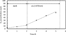
実施例5の組成物について、評価1と同様の方法により水素放出量を測定した。その結果を図33示す。同図より、非照射時に比べて、可視光照射により水素放出量が顕著に増加することを確認した。
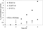
実施例9と10の粉末状の組成物について、窒素ガス中で可視光を照射して水素放出量を測定した結果を図34に示す。図中の矢印で示したタイミングで、可視光照射を開始した。同図には、比較のために、参考例1(電子供与体を添加していないホウ化水素含有シート)の結果も併せて示す。同図に示すように、粉末状の本組成物に可視光を照射すると非照射時に比べて可視光照射により水素放出量が顕著に増加することを確認した。
比較例3および4の粉末状の生成物について、Tauc-plotによるバンドギャップの算出をした。算出結果を図35に示す。同図には、比較のために、参考例1(電子供与体を添加していないホウ化水素含有シート)の結果も併せて示す。同図に示すように、ホウ化水素含有シートに炭素がドープされると、電子供与体を添加していないホウ化水素含有シート(C:0%)に比べてバンドギャップエネルギーが増加することを確認した。即ち、ホウ化水素含有シートの光吸収バンドが広がったため、可視光を吸収できないことがわかった。このことから、ホウ化水素含有シートに単に炭素などの異種元素をドープしても可視光の吸収がおこらないことがわかった。
10 水素発生部
11 原料供給タンク
12 溶媒供給路
13 ガス回収路
14 排出路
15 撹拌部
16 ガス供給路
17 気流発生部
18 薄型容器
19 搬送ベルト
20 外部刺激制御部
21 LED光源
30 ホウ化水素含有組成物
31 ホウ化水素含有シート
32 溶媒
40 担持ビーズ
41 ビーズ
50 フィルム
51 バインダー
Claims (12)
- (BH)n(n≧4、但しnは整数)からなる二次元ネットワークを有するホウ化水素含有シートと、電子供与体とを含有し、
前記電子供与体の少なくとも一部が、前記ホウ化水素含有シートの表面に担持され、
外部刺激により、前記電子供与体の電子が前記ホウ化水素含有シートに供給され、当該電子が注入された前記ホウ化水素含有シートから水素が発生するホウ化水素含有組成物。 - 前記電子供与体のLUMO(最低空軌道)または伝導帯準位が前記ホウ化水素含有シートの伝導帯準位よりも卑であることを特徴とする請求項1記載のホウ化水素含有組成物。
- 前記電子供与体は可視光線により励起され、前記励起された電子を前記ホウ化水素含有シートに供給することにより前記ホウ化水素含有シートから水素が発生する請求項1記載のホウ化水素含有組成物。
- 前記電子供与体は、有機化合物であることを特徴とする請求項1記載のホウ化水素含有組成物。
- 前記電子供与体は、カルボキシ基、ホスホノ基およびスルホン酸基の少なくともいずれかを有していることを特徴とする請求項1記載のホウ化水素含有組成物。
- 溶媒を含有することを特徴とする請求項1記載のホウ化水素含有組成物。
- 更に、正孔捕捉剤が含有されている請求項1記載のホウ化水素含有組成物。
- 前記正孔捕捉剤の酸化還元電位が、前記電子供与体のHOMO(最高被占軌道)または価電子帯準位よりも卑であることを特徴とする請求項7に記載のホウ化水素含有組成物。
- 更に、プロトン供与体を含むことを特徴とする請求項1記載のホウ化水素含有組成物。
- 前記プロトン供与体が酸であることを特徴とする請求項9記載のホウ化水素含有組成物。
- 請求項1~10のいずれかに記載のホウ化水素含有組成物を含む水素発生システムであって、
ホウ化水素含有組成物と、
前記ホウ化水素含有組成物への外部刺激のオンオフを制御する制御部と、
外部に水素を取り出す水素発生部とを備える水素発生システム。 - 請求項11に記載の水素発生システム、および前記水素発生システムから水素が供給される燃料電池を備える燃料電池システム。
Priority Applications (3)
| Application Number | Priority Date | Filing Date | Title |
|---|---|---|---|
| CN202280050298.XA CN117794848B (zh) | 2021-07-16 | 2022-07-14 | 含硼化氢组合物、产氢系统及燃料电池系统 |
| JP2023534852A JPWO2023286830A1 (ja) | 2021-07-16 | 2022-07-14 | |
| US18/578,782 US20240332577A1 (en) | 2021-07-16 | 2022-07-14 | Borohydride-containing composition, hydrogen generation system and fuel cell system |
Applications Claiming Priority (2)
| Application Number | Priority Date | Filing Date | Title |
|---|---|---|---|
| JP2021-117864 | 2021-07-16 | ||
| JP2021117864 | 2021-07-16 |
Publications (1)
| Publication Number | Publication Date |
|---|---|
| WO2023286830A1 true WO2023286830A1 (ja) | 2023-01-19 |
Family
ID=84920328
Family Applications (1)
| Application Number | Title | Priority Date | Filing Date |
|---|---|---|---|
| PCT/JP2022/027687 Ceased WO2023286830A1 (ja) | 2021-07-16 | 2022-07-14 | ホウ化水素含有組成物、水素発生システムおよび燃料電池システム |
Country Status (4)
| Country | Link |
|---|---|
| US (1) | US20240332577A1 (ja) |
| JP (1) | JPWO2023286830A1 (ja) |
| CN (1) | CN117794848B (ja) |
| WO (1) | WO2023286830A1 (ja) |
Cited By (1)
| Publication number | Priority date | Publication date | Assignee | Title |
|---|---|---|---|---|
| WO2025046934A1 (ja) * | 2023-08-31 | 2025-03-06 | 三菱重工業株式会社 | 水素吸蔵材料、水素放出・貯蔵システム |
Citations (2)
| Publication number | Priority date | Publication date | Assignee | Title |
|---|---|---|---|---|
| WO2018074518A1 (ja) * | 2016-10-18 | 2018-04-26 | 国立大学法人筑波大学 | 二次元ホウ化水素含有シート、二次元ホウ素化合物含有シートの製造方法 |
| JP2019218251A (ja) * | 2018-06-22 | 2019-12-26 | 国立大学法人東京工業大学 | 水素発生方法、水素発生システムおよび燃料電池システム |
Family Cites Families (1)
| Publication number | Priority date | Publication date | Assignee | Title |
|---|---|---|---|---|
| JP7578961B2 (ja) * | 2019-11-15 | 2024-11-07 | 国立大学法人東京科学大学 | 二次元ホウ化水素含有シートの製造方法、二次元ホウ化水素含有シート組成物およびその製造方法 |
-
2022
- 2022-07-14 CN CN202280050298.XA patent/CN117794848B/zh active Active
- 2022-07-14 US US18/578,782 patent/US20240332577A1/en active Pending
- 2022-07-14 JP JP2023534852A patent/JPWO2023286830A1/ja active Pending
- 2022-07-14 WO PCT/JP2022/027687 patent/WO2023286830A1/ja not_active Ceased
Patent Citations (2)
| Publication number | Priority date | Publication date | Assignee | Title |
|---|---|---|---|---|
| WO2018074518A1 (ja) * | 2016-10-18 | 2018-04-26 | 国立大学法人筑波大学 | 二次元ホウ化水素含有シート、二次元ホウ素化合物含有シートの製造方法 |
| JP2019218251A (ja) * | 2018-06-22 | 2019-12-26 | 国立大学法人東京工業大学 | 水素発生方法、水素発生システムおよび燃料電池システム |
Non-Patent Citations (2)
| Title |
|---|
| RIKU KAWAMURA, YOSHITAKA FUJIMOTO, RYOTA ISHIBIKI, TAIGA GOTO, SHIN-ICHI ITO, TAKESHI FUJITA, TOMOHARU TOKUNAGA, MASAHIRO MIYAUCHI: "Synthesis and evaluation of carbon-doped HB sheets", ABSTRACT BOOK OF ANNUAL MEETING OF THE JAPAN SOCIETY OF VACUUM AND SURFACE SCIENCE, 1 January 2020 (2020-01-01), pages 1 - 1, XP093024500, DOI: 10.14886/jvss.2020.0_114 * |
| TAKEHIRO KONDO , MASAHIRO MIYAUCHI: "Hydrogen Evolution Induced by UV Light Irradiation on Borohydride Sheets", VACUUM AND SURFACE SCIENCE, vol. 63, no. 7, 10 July 2020 (2020-07-10), pages 352 - 357, XP093024509, ISSN: 2433-5835, DOI: 10.1380/vss.63.352 * |
Cited By (1)
| Publication number | Priority date | Publication date | Assignee | Title |
|---|---|---|---|---|
| WO2025046934A1 (ja) * | 2023-08-31 | 2025-03-06 | 三菱重工業株式会社 | 水素吸蔵材料、水素放出・貯蔵システム |
Also Published As
| Publication number | Publication date |
|---|---|
| CN117794848B (zh) | 2026-04-10 |
| CN117794848A (zh) | 2024-03-29 |
| US20240332577A1 (en) | 2024-10-03 |
| JPWO2023286830A1 (ja) | 2023-01-19 |
Similar Documents
| Publication | Publication Date | Title |
|---|---|---|
| Guan et al. | Emerging trends of carbon‐based quantum dots: nanoarchitectonics and applications | |
| Liu et al. | Functional group modulation in carbon quantum dots for accelerating photocatalytic CO2 reduction | |
| Nakamura et al. | Sn (IV)-free tin perovskite films realized by in situ Sn (0) nanoparticle treatment of the precursor solution | |
| Mollick et al. | Ultrastable luminescent hybrid bromide perovskite@ MOF nanocomposites for the degradation of organic pollutants in water | |
| Bhunia et al. | Bimetallic PtAu alloy nanoparticles-integrated g-C3N4 hybrid as an efficient photocatalyst for water-to-hydrogen conversion | |
| Liu et al. | Fully conjugated covalent organic polymer with carbon-encapsulated Ni2P for highly sustained photocatalytic H2 production from seawater | |
| Liu et al. | g-C3N4 hydrogen-bonding viologen for significantly enhanced visible-light photocatalytic H2 evolution | |
| Chen et al. | Synthesis and hybridization of CuInS 2 nanocrystals for emerging applications | |
| Ran et al. | Progress of covalent organic framework photocatalysts: from crystallinity–stability dilemma to photocatalytic performance improvement | |
| Xu et al. | A CsPbBr3 perovskite quantum dot/graphene oxide composite for photocatalytic CO2 reduction | |
| Fan et al. | Construction of graphitic C3N4-based intramolecular donor–acceptor conjugated copolymers for photocatalytic hydrogen evolution | |
| Kaur et al. | Efficient photocatalytic and photovoltaic applications with nanocomposites between CdTe QDs and an NTU-9 MOF | |
| Ma et al. | Bioinspired photoelectric conversion system based on carbon-quantum-dot-doped dye–semiconductor complex | |
| Li et al. | Carbon and graphene quantum dots for optoelectronic and energy devices: a review | |
| Leventis et al. | Transient optical studies of interfacial charge transfer at nanostructured metal oxide/PbS quantum dot/organic hole conductor heterojunctions | |
| Wang et al. | Enhanced performance of perovskite solar cells by ultraviolet-ozone treatment of mesoporous TiO2 | |
| Zhang et al. | Noble metal-free photocatalysts consisting of graphitic carbon nitride, nickel complex, and nickel oxide nanoparticles for efficient hydrogen generation | |
| Bera et al. | Design of a CdS/CdSe heterostructure for efficient H2 generation and photovoltaic applications | |
| Song et al. | Ultrathin carbon nitride with atomic-level intraplane implantation of graphited carbon ring domain for superior photocatalytic activity in the visible/near-infrared region | |
| KR102100318B1 (ko) | 금속 담지된 원자 양자 클러스터를 이용한 광의 광변환 | |
| Voitekhovich et al. | Tetrazoles: unique capping ligands and precursors for nanostructured materials | |
| JP7079932B2 (ja) | 水素発生方法、水素発生システムおよび燃料電池システム | |
| CN105377973A (zh) | 杂化复合纳米材料 | |
| Das et al. | Synergistic effect of metal complex and dual doped graphitic carbon nitride for superior photocatalytic hydrogen evolution | |
| Spitaleri et al. | Fast and efficient sun light photocatalytic activity of Au_ZnO core–shell nanoparticles prepared by a one-pot synthesis |
Legal Events
| Date | Code | Title | Description |
|---|---|---|---|
| 121 | Ep: the epo has been informed by wipo that ep was designated in this application |
Ref document number: 22842172 Country of ref document: EP Kind code of ref document: A1 |
|
| WWE | Wipo information: entry into national phase |
Ref document number: 2023534852 Country of ref document: JP |
|
| WWE | Wipo information: entry into national phase |
Ref document number: 18578782 Country of ref document: US |
|
| WWE | Wipo information: entry into national phase |
Ref document number: 202280050298.X Country of ref document: CN |
|
| NENP | Non-entry into the national phase |
Ref country code: DE |
|
| 122 | Ep: pct application non-entry in european phase |
Ref document number: 22842172 Country of ref document: EP Kind code of ref document: A1 |