WO2023286172A1 - トラヒック分析装置、トラヒック分析方法、および、トラヒック分析プログラム - Google Patents
トラヒック分析装置、トラヒック分析方法、および、トラヒック分析プログラム Download PDFInfo
- Publication number
- WO2023286172A1 WO2023286172A1 PCT/JP2021/026340 JP2021026340W WO2023286172A1 WO 2023286172 A1 WO2023286172 A1 WO 2023286172A1 JP 2021026340 W JP2021026340 W JP 2021026340W WO 2023286172 A1 WO2023286172 A1 WO 2023286172A1
- Authority
- WO
- WIPO (PCT)
- Prior art keywords
- traffic
- calculation
- emulator
- next time
- time
- Prior art date
- Legal status (The legal status is an assumption and is not a legal conclusion. Google has not performed a legal analysis and makes no representation as to the accuracy of the status listed.)
- Ceased
Links
Images



Classifications
-
- H—ELECTRICITY
- H04—ELECTRIC COMMUNICATION TECHNIQUE
- H04L—TRANSMISSION OF DIGITAL INFORMATION, e.g. TELEGRAPHIC COMMUNICATION
- H04L43/00—Arrangements for monitoring or testing data switching networks
- H04L43/50—Testing arrangements
-
- H—ELECTRICITY
- H04—ELECTRIC COMMUNICATION TECHNIQUE
- H04L—TRANSMISSION OF DIGITAL INFORMATION, e.g. TELEGRAPHIC COMMUNICATION
- H04L41/00—Arrangements for maintenance, administration or management of data switching networks, e.g. of packet switching networks
- H04L41/14—Network analysis or design
- H04L41/142—Network analysis or design using statistical or mathematical methods
-
- H—ELECTRICITY
- H04—ELECTRIC COMMUNICATION TECHNIQUE
- H04L—TRANSMISSION OF DIGITAL INFORMATION, e.g. TELEGRAPHIC COMMUNICATION
- H04L41/00—Arrangements for maintenance, administration or management of data switching networks, e.g. of packet switching networks
- H04L41/14—Network analysis or design
- H04L41/147—Network analysis or design for predicting network behaviour
Definitions
- the present invention relates to a traffic analysis device, a traffic analysis method, and a traffic analysis program.
- Patent Literature 1 describes a communication band calculation device that predicts future user traffic volume and calculates the amount of band equipment required for communication services. As a result, the communication service provider's economic efficiency is improved by calculating the proper amount of communication resources installed.
- Traffic emulation which finely predicts individual traffic on a flow-by-flow basis, is more effective in detecting unauthorized communication than the rough prediction value of traffic volume as in Patent Document 1.
- the traffic emulator simulates (mirrors) each traffic flowing through the real network at the current time (t) in the virtual space, and with each traffic at the current time (t) as the starting point, the virtual space at the next time (t+1) predict the (ideal) traffic conditions that conform to the protocol conventions of
- the traffic emulator can detect user traffic that violates the protocol rules by comparing the ideal traffic state at the next time with the user traffic state in the real space at the next time.
- the traffic emulator is required to have extremely high (real-time) calculation capability.
- the main problem of the present invention is to appropriately reduce the calculation cost when predicting the traffic state at the next time (t+1) from the traffic state at the current time (t).
- the traffic analysis device of the present invention has the following features. According to the present invention, each traffic on the real network system at the current time is mirrored in the virtual space, and the protocol control of each traffic is executed in the virtual space, so that the state of the traffic on the real network system at the next time can be obtained.
- a computing traffic emulator and a calculation exclusion unit that excludes, from the calculation target of the traffic emulator, the traffic for which the calculation result of the traffic emulator is predicted not to be obtained by the next time, for each mirrored traffic.
- FIG. 1 is a configuration diagram of a traffic analysis device according to this embodiment
- FIG. 1 is a hardware configuration diagram of a traffic analysis device according to this embodiment
- FIG. FIG. 4 is an explanatory diagram showing an outline of processing of the traffic analysis device according to the present embodiment
- 4 is a sequence diagram showing processing of the traffic analysis device according to the present embodiment
- FIG. 4 is a comparison table for claiming the effect of the traffic analysis device according to this embodiment
- FIG. 1 is a configuration diagram of a traffic analysis device 1. As shown in FIG.
- the traffic analysis device 1 has a calculation time determination unit 11 , a traffic model management unit 12 , a traffic emulator 13 , an analysis exclusion unit 14 and a traffic comparison unit 15 .
- the real network system 2 is an actual network system to be analyzed by the traffic analysis device 1 .
- the traffic emulator 13 mirrors each traffic on the real network system 2 at the current time (t) in the virtual space, and executes protocol control of each traffic in the virtual space, so that at the next time (t+1) Calculate the state of traffic on the real network system 2 .
- the calculation time determination unit 11 Based on the calculation time of the traffic emulator 13 from when the traffic mirrored at the current time is input to the traffic emulator 13 until when the traffic state at the next time is output, the calculation time determination unit 11 (calculation exclusion unit) It is determined whether or not the calculation result can be obtained by the next time.
- the calculation time determination unit 11 outputs the determination result to the analysis exclusion unit 14 .
- the analysis exclusion unit 14 (calculation exclusion unit) removes from the calculation target of the traffic emulator 13 traffic for which the calculation result of the traffic emulator 13 is predicted not to be obtained by the next time, for each traffic mirrored from the real network system 2. exclude.
- the analysis exclusion unit 14 determines traffic to be excluded from calculation targets by, for example, one of the following methods.
- Method 1 Preliminary estimation
- Methodhod 2 Confirmation of progress during calculation
- the calculation result of the traffic emulator 13 is as follows. Traffic that is predicted not to be obtained by the time is excluded from calculation targets of the traffic emulator 13 .
- the traffic model management unit 12 manages, as a traffic model, protocol-defined control information for the traffic emulator 13 to execute the protocol control of each traffic in the virtual space.
- the traffic emulator 13 reads the traffic model for each traffic protocol from the traffic model management unit 12 and uses it to calculate the traffic state.
- the traffic comparison unit 15 notifies the real network system 2 of the traffic that does not satisfy the operation as abnormal traffic. do.
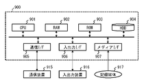
- FIG. 2 is a hardware configuration diagram of the traffic analysis device 1.
- Traffic analysis apparatus 1 is configured as computer 900 having CPU 901 , RAM 902 , ROM 903 , HDD 904 , communication I/F 905 , input/output I/F 906 and media I/F 907 .
- Communication I/F 905 is connected to an external communication device 915 .
- Input/output I/F 906 is connected to input/output device 916 .
- a media I/F 907 reads and writes data from a recording medium 917 .
- the CPU 901 controls each processing unit by executing a program (also called an application or an app for short) read into the RAM 902 . This program can be distributed via a communication line or recorded on a recording medium 917 such as a CD-ROM for distribution.
- a program also called an application or an app for short
- FIG. 3 is an explanatory diagram showing an overview of the processing of the traffic analysis device 1.
- a state 101 is a bar graph representing the expected time required for calculation of each of the four traffics VA, VB, VC, and VD mirrored by the traffic emulator 13 at the current time (t). At the current time (t), it is expected that traffic VA and VB will be calculated by the next time (t+1), but traffic VC and VD will not be calculated by the next time (t+1). rice field.
- a state 102 is a bar graph representation of the computation times of the traffic VA, VB, and VC.
- the calculation time determining unit 11 selects the traffic VC and VD whose calculation cannot be completed in time in the state 101 as candidates to be excluded from future calculation targets.
- the analysis exclusion unit 14 excludes the low-priority traffic VD from the calculation target while leaving the high-priority traffic VC as the calculation target. Therefore, in the state 102, by allocating the surplus computational capacity obtained by interrupting the computation of the traffic VD to the traffic VC, the computation of the traffic VC was completed earlier than the expected time (at the point of time indicated by the wavy vertical line). In this way, the traffic analysis apparatus 1 early excludes part of the mirrored traffic from the calculation target, thereby increasing the amount of traffic that can be calculated by the next time (t+1).
- FIG. 4 is a sequence diagram showing the processing of the traffic analysis device 1. As shown in FIG. In S101, when the traffic emulator 13 receives real traffic (or information indicating its status) at the current time from the real network system 2, it notifies the analysis exclusion unit 14 of the real traffic as a candidate for exclusion processing in S106.
- the traffic emulator 13 acquires from the traffic model management unit 12 the protocol operation contents of the traffic at the next time using the protocol information of the actual traffic at the current time received in S101 as a search key.
- the traffic comparison unit 15 acquires information (protocol specification information) for specifying the protocol operation contents acquired in S102a from the traffic model management unit 12 for the abnormality determination processing in S112.
- the traffic emulator 13 simulates the protocol operation for each flow of traffic on the real network system 2 in a virtual space, thereby calculating the traffic state of the next time based on the traffic state of the current time. This calculation process transitions in the order of start of calculation in S103a, during calculation in S103b, and completion of calculation in S103c. At the start of calculation in S103a, the traffic emulator 13 mirrors the actual traffic at the current time notified in S101 on the virtual space. After that, the traffic emulator 13 reflects the protocol operation contents acquired in S102a for each traffic in the virtual space, thereby starting calculation for transitioning to the traffic state at the next time when the network conditions in the virtual space are changed.
- the end point of the estimated time is the calculation completion time of S103c.
- the starting point of the estimated time may be the time when the actual traffic at the current time is received in S101, or the calculation start time of S103a.
- the traffic emulator 13 notifies the calculation time determination unit 11 of the estimated time for each traffic.
- the calculation time determination unit 11 determines that the future time from the current time (t) by the estimated time of S104 is calculated by the determination formula "current time (t) + estimated time ⁇ next time (t+1)". Determine whether or not the time (t+1) has passed. That is, it is predicted in advance that the traffic determined in S105a to have exceeded the next time (t+1) will not be calculated by the traffic emulator 13 by the next time (t+1).
- the calculation time determination unit 11 notifies the analysis exclusion unit 14 of the traffic that cannot be calculated in time (Yes in S105a) as exclusion candidate traffic that is a candidate for exclusion from the calculation target of the traffic emulator 13.
- the analysis exclusion unit 14 determines to exclude part or all of the exclusion candidate traffic notified in S105b from the calculation targets of the traffic emulator 13.
- FIG. the analysis exclusion unit 14 may use the following method to determine whether or not to actually exclude traffic from the calculation target and in which order the calculation of the excluded traffic is interrupted.
- Exclusion method 1 The priority for the next time is determined in advance for each terminal that transmits and receives traffic, and the traffic of terminals with lower priority is more likely to be excluded from calculation targets, or the traffic is calculated in the earliest order. interrupt.
- Exclusion method 2 The traffic state calculated so far is collated with the protocol stipulated information of S102b, and the protocol stipulated information is not matched (the operation is not in accordance with the protocol stipulated, or the ) When traffic is found, it is made easier to be excluded from the calculation target, or the traffic calculation is interrupted in the early order.
- Traffic with a smaller degree of progress in the traffic state calculated up to the present is more likely to be excluded from the calculation target, or the traffic calculation is interrupted in the earliest order. For example, if the state of being able to calculate until the next time is 100%, the traffic A whose calculation is 20% completed is excluded first, and the traffic A whose calculation is 60% completed is excluded later.
- the analysis exclusion unit 14 notifies the traffic emulator 13 of an instruction to exclude the traffic determined in S106 from the calculation target.
- the traffic emulator 13 suspends (or forcibly terminates) the calculation of the traffic for which the exclusion instruction was received in S107 from the traffic being calculated in S103b.
- the surplus power generated in the computational capacity of the computer on which the traffic emulator 13 operates can be utilized for computation of other traffic that has not been excluded, resulting in a traffic flow whose computation will be completed (S103c) by the next time. number can be increased.
- the calculation time determination unit 11 determines in S105a whether the time will exceed the next time based on the estimated time estimated before the traffic calculation. On the other hand, instead of S105a, the calculation time determination unit 11 compares the progress of the traffic state calculated up to now with the remaining time until the next time, thereby determining whether the time has passed until the next time. good too.
- the traffic emulator 13 notifies the traffic comparator 15 of the virtual traffic in the virtual space at the next time after the calculation is completed (Yes in S103c).
- Each of the above processes from S101 to S108 is executed during the period from the current time (t) to the next time (t+1).
- S111 and subsequent steps are processes to be executed after the next time (t+1).
- the traffic comparison unit 15 receives the real traffic at the next time (t+1) from the real network system 2, it compares the real traffic with the virtual traffic at the next time received at S108. If the comparison results do not match, the traffic comparison unit 15 considers the actual traffic at the next time (t+1) to be abnormal traffic.
- the traffic comparison unit 15 determines whether or not the following abnormality exists as a result of comparing the two traffics in S111.
- protocol specification information for TCP Transmission Control Protocol
- Virtual traffic exists, but the corresponding real traffic does not exist.
- virtual traffic includes a combination of data signals and Acks, but real traffic includes only data signals and no Acks.
- node B detects an anomaly indicating violation of protocol rules (nonfulfillment of Ack reply obligation).
- Real traffic and virtual traffic correspond to each other as flows, but the state of the real traffic and the state of the virtual traffic do not match, and the state of the real traffic is the protocol stipulation information (sequence number of S102b). match rule).
- virtual traffic has a combination of a data signal with a sequence number of 101 and an Ack, but real traffic has a data signal with a sequence number of 101 and an Ack with a sequence number of 109. In this case, an anomaly is detected to the effect that the operation of the actual traffic violates protocol regulations (mismatch of sequence numbers).
- the traffic comparison unit 15 checks the result of the comparison in S111 and the fact of the abnormality (whether or not there is an abnormality, what is the cause of the abnormality) in the actual traffic found in (abnormality 1) to (abnormality 3) in S112. etc.) is added.
- the traffic comparison unit 15 returns to the real network system 2 the real traffic of the next time to which the anomaly flag is attached.
- each device in the actual network system 2 can take measures against anomalies, such as discarding actual traffic to which anomaly flags have been assigned, or displaying the contents of the anomaly flags on the administrator's screen.
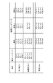
- FIG. 5 is a comparison table for claiming the effect of the traffic analysis device 1.
- the first column (time) of the comparison table indicates the time of each state under calculation.
- the second column (actual network) of the comparison table is a list of real traffic present on the real network system 2 .
- the first character of the real traffic identifier (for example, "RTa(t)") is R (Real) for real traffic or V (Virtual) for virtual traffic, and the second character is T (Traffic) indicating traffic. attached.
- the third character of the identifier of the actual traffic indicates the identifier of the flow (a, b, c, d), followed by the time information in the first column such as (t) in brackets.
- the third column (hypothetical 1) of the comparison table shows the hypothetical traffic when all the traffic is calculated by the next time in a computer environment (such as a supercomputer) in which the traffic analysis device 1 is sufficiently supplied with computing power. show.
- Columns 4 and 5 (hypothetical 2 and 3) of the comparison table indicate that part of the traffic will not be calculated by the next time due to a computer environment (general personal computer, etc.) in which the computing power of the traffic analysis device 1 is limited. shows the virtual traffic of The difference between the 4th column (hypothetical 2) and the 5th column (hypothetical 3) is whether the process of excluding some traffic from the calculation target shown in FIG. 3 is not applied (hypothetical 2) or applied (hypothetical 2) Hypothetical 3) or
- the first row of the comparison table indicates that the actual traffic existing on the real network system 2 at the current time (t) is mirrored to (virtual 1, 2, 3) respectively. That is, four sets of mirroring are performed: RTa(t) ⁇ VTa(t), RTb(t) ⁇ VTb(t), RTc(t) ⁇ VTc(t), and RTd(t) ⁇ VTd(t).
- the second row of the comparison table shows the traffic conditions at the next time (t+1). Normal traffic RTa(t+1), RTb(t+1), and RTc(t+1) remain from the real network system 2, but RTd(t+1) disappears as abnormal traffic and RTe(t +1) is added.
- VTc(t) ⁇ VTc Four sets of traffic conditions (t+1), VTd(t) ⁇ VTd(t+1) can be calculated by the next time. Therefore, by comparing the second and third columns at the next time (t+1), abnormal traffic can be detected as follows.
- ⁇ RTa(t+1) VTa(t+1) ⁇ Normal traffic
- VTb(t+1) VTb(t+1) ⁇ Normal traffic
- VTc(t+1) VTc(t+1) ⁇ Normal traffic Traffic Mismatch of VTd(t+1) ⁇ Abnormal traffic Mismatch of RTe(t+1) ⁇ Abnormal traffic
- the traffic analysis apparatus 1 of the present invention mirrors each traffic on the real network system 2 at the current time in the virtual space, and executes protocol control of each traffic in the virtual space so that the real network system 2 at the next time a traffic emulator 13 for calculating traffic conditions above; and an analysis exclusion unit 14 for excluding, from the calculation target of the traffic emulator 13, the traffic for which the calculation result of the traffic emulator 13 is predicted not to be obtained by the next time, for each mirrored traffic.
- the analysis exclusion unit 14 refers to the amount of processing for executing the protocol control of each traffic in the virtual space and the processing capacity of the computer on which the traffic emulator 13 operates, thereby predicting the calculation required for the traffic emulator 13. It is characterized by estimating the time and excluding from the calculation target of the traffic emulator 13 the traffic in which the future time exceeds the next time by the expected time from the current time.
- the analysis excluding unit 14 determines whether the calculation result of the traffic emulator 13 is the next time, based on the degree of progress of the traffic state calculated by the traffic emulator 13 up to now and the remaining time from the current time to the next time. It is characterized by excluding traffic that is predicted to be unobtainable by the time the traffic emulator 13 is calculated.
- the traffic analysis device 1 further has a traffic comparison unit 15,
- the traffic comparison unit 15 compares the traffic state at the next time calculated by the traffic emulator 13 with the traffic state on the real network system 2 at the next time, and treats inconsistent traffic as abnormal traffic to the real network system 2. It is characterized by notifying.
- the traffic comparison unit 15 treats the unsatisfied traffic as abnormal traffic on the real network. It is characterized by notifying the system 2 .
- unauthorized communication can be detected appropriately even if there is room for interpretation in the operations specified by the protocol, such as the ability to omit the transmission of predetermined control messages.
- traffic analysis device 1 traffic analysis device 2 actual network system 11 calculation time determination unit (calculation exclusion unit) 12 traffic model management unit 13 traffic emulator 14 analysis exclusion unit (calculation exclusion unit) 15 traffic comparator
Landscapes
- Engineering & Computer Science (AREA)
- Computer Networks & Wireless Communication (AREA)
- Signal Processing (AREA)
- Physics & Mathematics (AREA)
- Algebra (AREA)
- General Physics & Mathematics (AREA)
- Mathematical Analysis (AREA)
- Mathematical Optimization (AREA)
- Mathematical Physics (AREA)
- Probability & Statistics with Applications (AREA)
- Pure & Applied Mathematics (AREA)
- Data Exchanges In Wide-Area Networks (AREA)
Abstract
トラヒック分析装置(1)は、現時刻における実ネットワークシステム(2)上の各トラヒックを仮想空間上にミラーリングし、各トラヒックのプロトコル制御を仮想空間上で実行することで、次時刻における実ネットワークシステム(2)上のトラヒックの状態を計算するトラヒックエミュレータ(13)と、ミラーリングされた各トラヒックについて、トラヒックエミュレータ(13)の計算結果が次時刻までに得られないと予測されるトラヒックを、トラヒックエミュレータ(13)の計算対象から除外する分析除外部(14)と、を有する。
Description
本発明は、トラヒック分析装置、トラヒック分析方法、および、トラヒック分析プログラムに関する。
将来のトラヒック量を予測する技術が提案されている。例えば、特許文献1には、将来のユーザトラヒック量を予測し、通信サービスに必要な帯域設備量を算出する通信帯域算出装置が記載されている。これにより、過不足のない通信リソースの設備量を算出することで、通信サービスの供給者の経済性を向上させる。
将来のトラヒック量を予測する技術を、不正通信の検知に応用する場合を検討する。不正通信の検知には、特許文献1のようなトラヒック量という大まかな予測値よりも、個々のトラヒックをフロー単位で細かく予測するトラヒックエミュレーションが有効である。
トラヒックエミュレータは、現時刻(t)の実網を流れる各トラヒックを仮想空間上に模擬(ミラーリング)し、現時刻(t)の各トラヒックを起点として、次時刻(t+1)の仮想空間上のプロトコル規約に適合した(理想的な)トラヒック状態を予測する。
トラヒックエミュレータは、現時刻(t)の実網を流れる各トラヒックを仮想空間上に模擬(ミラーリング)し、現時刻(t)の各トラヒックを起点として、次時刻(t+1)の仮想空間上のプロトコル規約に適合した(理想的な)トラヒック状態を予測する。
なお、現時刻(t)とは実網を観測するターゲット時刻であり、次時刻(t+1)とは現時刻の次のタイミングで実網を観測するターゲット時刻である。そして、トラヒックエミュレータは、次時刻の理想的なトラヒック状態と、次時刻の実空間上のユーザトラヒック状態とを比較することで、プロトコル規約に違反したユーザトラヒックを検出できる。
しかし、大容量の基幹ネットワーク上を流れるトラヒック量は、1波長あたり10[Gbps],100[Gbps]など大量であるため、トラヒックエミュレータが計算対象とするトラヒックのフロー数も膨大である。そのため、現時刻(t)から次時刻(t+1)までの計算間隔を短縮化するほど(例えば10秒ごと)、トラヒックエミュレータには非常に高い(リアルタイムな)計算能力が求められる。
よって、いくらトラヒックエミュレータが膨大なトラヒックを正しく計算できたとしても、計算完了時刻が次時刻(t+1)に間に合わなければ、その計算結果を不正通信の検知には応用できなくなってしまう。
なお、特許文献1のような従来のトラヒック量を予測する技術では、このような厳しい計算時間の制約が存在しなかったので、そもそも計算結果が次時刻までに得られないトラヒックに対する計算コストを低減することは検討されてこなかった。
なお、特許文献1のような従来のトラヒック量を予測する技術では、このような厳しい計算時間の制約が存在しなかったので、そもそも計算結果が次時刻までに得られないトラヒックに対する計算コストを低減することは検討されてこなかった。
そこで、本発明は、現時刻(t)のトラヒック状態から次時刻(t+1)のトラヒック状態を予測するときに、適切に計算コストを低減させることを主な課題とする。
前記課題を解決するために、本発明のトラヒック分析装置は、以下の特徴を有する。
本発明は、現時刻における実ネットワークシステム上の各トラヒックを仮想空間上にミラーリングし、各トラヒックのプロトコル制御を仮想空間上で実行することで、次時刻における前記実ネットワークシステム上のトラヒックの状態を計算するトラヒックエミュレータと、
ミラーリングされた各トラヒックについて、前記トラヒックエミュレータの計算結果が次時刻までに得られないと予測されるトラヒックを、前記トラヒックエミュレータの計算対象から除外する計算除外部と、を有することを特徴とする。
本発明は、現時刻における実ネットワークシステム上の各トラヒックを仮想空間上にミラーリングし、各トラヒックのプロトコル制御を仮想空間上で実行することで、次時刻における前記実ネットワークシステム上のトラヒックの状態を計算するトラヒックエミュレータと、
ミラーリングされた各トラヒックについて、前記トラヒックエミュレータの計算結果が次時刻までに得られないと予測されるトラヒックを、前記トラヒックエミュレータの計算対象から除外する計算除外部と、を有することを特徴とする。
本発明によれば、現時刻(t)のトラヒック状態から次時刻(t+1)のトラヒック状態を予測するときに、適切に計算コストを低減させることができる。
以下、本発明の一実施形態について、図面を参照して詳細に説明する。
図1は、トラヒック分析装置1の構成図である。
トラヒック分析装置1は、計算時間判定部11と、トラヒックモデル管理部12と、トラヒックエミュレータ13と、分析除外部14と、トラヒック比較部15と有する。
実ネットワークシステム2は、トラヒック分析装置1の分析対象となる実際のネットワークシステムである。
トラヒック分析装置1は、計算時間判定部11と、トラヒックモデル管理部12と、トラヒックエミュレータ13と、分析除外部14と、トラヒック比較部15と有する。
実ネットワークシステム2は、トラヒック分析装置1の分析対象となる実際のネットワークシステムである。
トラヒックエミュレータ13は、現時刻(t)における実ネットワークシステム2上の各トラヒックを仮想空間上にミラーリングし、各トラヒックのプロトコル制御を仮想空間上で実行することで、次時刻(t+1)における実ネットワークシステム2上のトラヒックの状態を計算する。
計算時間判定部11(計算除外部)は、現時刻でミラーリングしたトラヒックをトラヒックエミュレータ13に入力してから、次時刻のトラヒックの状態を出力するまでのトラヒックエミュレータ13の計算時間をもとに、計算結果が次時刻までに得られるか否かを判定する。計算時間判定部11は、判定結果を分析除外部14に出力する。
分析除外部14(計算除外部)は、実ネットワークシステム2からミラーリングする各トラヒックについて、トラヒックエミュレータ13の計算結果が次時刻までに得られないと予測されるトラヒックを、トラヒックエミュレータ13の計算対象から除外する。
分析除外部14(計算除外部)は、実ネットワークシステム2からミラーリングする各トラヒックについて、トラヒックエミュレータ13の計算結果が次時刻までに得られないと予測されるトラヒックを、トラヒックエミュレータ13の計算対象から除外する。
分析除外部14は、例えば、以下のいずれかの手法により、計算対象から除外するトラヒックを決定する。
(手法1:事前見積もり)各トラヒックのプロトコル制御を仮想空間上で実行する処理量と、トラヒックエミュレータ13が動作する計算機の処理能力とを参照して、トラヒックエミュレータ13の計算に要する予想時間を見積もり、現時刻から予想時間分だけ将来の時刻が次時刻を超過したトラヒックを、トラヒックエミュレータ13の計算対象から除外する。
(手法2:計算中の進捗度合い確認)現在までにトラヒックエミュレータ13が計算したトラヒックの状態の進捗度合いと、現在から次時刻までの残り時間とをもとに、トラヒックエミュレータ13の計算結果が次時刻までに得られないと予測されるトラヒックを、トラヒックエミュレータ13の計算対象から除外する。
(手法1:事前見積もり)各トラヒックのプロトコル制御を仮想空間上で実行する処理量と、トラヒックエミュレータ13が動作する計算機の処理能力とを参照して、トラヒックエミュレータ13の計算に要する予想時間を見積もり、現時刻から予想時間分だけ将来の時刻が次時刻を超過したトラヒックを、トラヒックエミュレータ13の計算対象から除外する。
(手法2:計算中の進捗度合い確認)現在までにトラヒックエミュレータ13が計算したトラヒックの状態の進捗度合いと、現在から次時刻までの残り時間とをもとに、トラヒックエミュレータ13の計算結果が次時刻までに得られないと予測されるトラヒックを、トラヒックエミュレータ13の計算対象から除外する。
トラヒックモデル管理部12には、トラヒックエミュレータ13が各トラヒックのプロトコル制御を仮想空間上で実行するための、プロトコルに規定された制御の情報が、トラヒックモデルとして管理されている。トラヒックエミュレータ13はトラヒックモデル管理部12からトラヒックのプロトコルごとにトラヒックモデルを読み出して、トラヒックの状態を計算するために使用する。
トラヒック比較部15は、次時刻における実ネットワークシステム2上のトラヒックの状態が、そのトラヒックのプロトコルで規定された動作を満たさない場合に、その満たさないトラヒックを異常なトラヒックとして実ネットワークシステム2に通知する。
トラヒック比較部15は、次時刻における実ネットワークシステム2上のトラヒックの状態が、そのトラヒックのプロトコルで規定された動作を満たさない場合に、その満たさないトラヒックを異常なトラヒックとして実ネットワークシステム2に通知する。
図2は、トラヒック分析装置1のハードウェア構成図である。
トラヒック分析装置1は、CPU901と、RAM902と、ROM903と、HDD904と、通信I/F905と、入出力I/F906と、メディアI/F907とを有するコンピュータ900として構成される。
通信I/F905は、外部の通信装置915と接続される。入出力I/F906は、入出力装置916と接続される。メディアI/F907は、記録媒体917からデータを読み書きする。さらに、CPU901は、RAM902に読み込んだプログラム(アプリケーションや、その略のアプリとも呼ばれる)を実行することにより、各処理部を制御する。そして、このプログラムは、通信回線を介して配布したり、CD-ROM等の記録媒体917に記録して配布したりすることも可能である。
トラヒック分析装置1は、CPU901と、RAM902と、ROM903と、HDD904と、通信I/F905と、入出力I/F906と、メディアI/F907とを有するコンピュータ900として構成される。
通信I/F905は、外部の通信装置915と接続される。入出力I/F906は、入出力装置916と接続される。メディアI/F907は、記録媒体917からデータを読み書きする。さらに、CPU901は、RAM902に読み込んだプログラム(アプリケーションや、その略のアプリとも呼ばれる)を実行することにより、各処理部を制御する。そして、このプログラムは、通信回線を介して配布したり、CD-ROM等の記録媒体917に記録して配布したりすることも可能である。
図3は、トラヒック分析装置1の処理の概要を示す説明図である。
状態101は、現時刻(t)の時点でトラヒックエミュレータ13がミラーリングした4つのトラヒックVA,VB,VC,VDそれぞれの計算に要する予想時間を、棒グラフ表示したものである。
トラヒックVA,VBは次時刻(t+1)までに計算が間に合うが、トラヒックVC,VDは次時刻(t+1)までに計算が間に合わないことが、現時刻(t)の時点で予想された。
状態101は、現時刻(t)の時点でトラヒックエミュレータ13がミラーリングした4つのトラヒックVA,VB,VC,VDそれぞれの計算に要する予想時間を、棒グラフ表示したものである。
トラヒックVA,VBは次時刻(t+1)までに計算が間に合うが、トラヒックVC,VDは次時刻(t+1)までに計算が間に合わないことが、現時刻(t)の時点で予想された。
状態102は、トラヒックVA,VB,VCの計算時間を、棒グラフ表示したものである。
ここで、計算時間判定部11は、状態101において計算が間に合わないトラヒックVC,VDを今後の計算対象から除外する候補とした。分析除外部14は、優先度の高いトラヒックVCを計算対象として残しつつ、優先度の低いトラヒックVDを計算対象から除外した。
よって、状態102では、トラヒックVDの計算を中断して得られる計算能力の余力を、トラヒックVCに割り当てることで、トラヒックVCは予想時間よりも早く計算が完了した(波線縦線の時点)。
このように、トラヒック分析装置1は、ミラーリングしたトラヒックの一部を計算対象から早期に除外することで、次時刻(t+1)までに計算が間に合うトラヒックを増やすことができる。
ここで、計算時間判定部11は、状態101において計算が間に合わないトラヒックVC,VDを今後の計算対象から除外する候補とした。分析除外部14は、優先度の高いトラヒックVCを計算対象として残しつつ、優先度の低いトラヒックVDを計算対象から除外した。
よって、状態102では、トラヒックVDの計算を中断して得られる計算能力の余力を、トラヒックVCに割り当てることで、トラヒックVCは予想時間よりも早く計算が完了した(波線縦線の時点)。
このように、トラヒック分析装置1は、ミラーリングしたトラヒックの一部を計算対象から早期に除外することで、次時刻(t+1)までに計算が間に合うトラヒックを増やすことができる。
図4は、トラヒック分析装置1の処理を示すシーケンス図である。
S101として、トラヒックエミュレータ13は、現時刻における実トラヒック(またはその状態を示す情報)を実ネットワークシステム2から受信すると、その実トラヒックをS106の除外処理の候補として、分析除外部14に通知する。
S101として、トラヒックエミュレータ13は、現時刻における実トラヒック(またはその状態を示す情報)を実ネットワークシステム2から受信すると、その実トラヒックをS106の除外処理の候補として、分析除外部14に通知する。
S102aとして、トラヒックエミュレータ13は、S101で受信した現時刻における実トラヒックのプロトコル情報を検索キーとして、そのトラヒックの次時刻のプロトコル動作内容を、トラヒックモデル管理部12から取得する。
S102bとして、トラヒック比較部15は、S102aで取得されたプロトコル動作内容を規定するための情報(プロトコル規定情報)を、S112の異常判定処理のためにトラヒックモデル管理部12から取得する。
S102bとして、トラヒック比較部15は、S102aで取得されたプロトコル動作内容を規定するための情報(プロトコル規定情報)を、S112の異常判定処理のためにトラヒックモデル管理部12から取得する。
トラヒックエミュレータ13は、実ネットワークシステム2上のトラヒックのフローごとのプロトコル動作を仮想空間上で模擬実行することで、現時刻のトラヒック状態から、次時刻のトラヒック状態を計算する。この計算過程は、S103aの計算開始→S103bの計算中→S103cの計算完了の順に遷移する。
S103aの計算開始時点では、トラヒックエミュレータ13は、S101で通知された現時刻における実トラヒックを、仮想空間上にミラーリングする。その後、トラヒックエミュレータ13は、仮想空間上の各トラヒックについて、S102aで取得したプロトコル動作内容を反映させることで、仮想空間のネットワーク条件が変更された次時刻のトラヒック状態に遷移させる計算を開始する。
S103aの計算開始時点では、トラヒックエミュレータ13は、S101で通知された現時刻における実トラヒックを、仮想空間上にミラーリングする。その後、トラヒックエミュレータ13は、仮想空間上の各トラヒックについて、S102aで取得したプロトコル動作内容を反映させることで、仮想空間のネットワーク条件が変更された次時刻のトラヒック状態に遷移させる計算を開始する。
また、S103aの計算開始時点では、トラヒックエミュレータ13は、トラヒックごとの次時刻のトラヒック状態を計算するための予想時間をトラヒックごとに見積もる。この見積処理は、例えば、(予想時間)=(現時刻から次時刻までプロトコル動作内容を反映させるための計算量)÷(トラヒックエミュレータ13が動作する計算機の計算能力)であり、計算機の計算能力は、CPUのコア数やクロック数などから求める。
予想時間の終点は、S103cの計算完了時刻である。予想時間の起点は、S101で現時刻における実トラヒックを受信した時刻としてもよいし、S103aの計算開始時刻としてもよい。
予想時間の終点は、S103cの計算完了時刻である。予想時間の起点は、S101で現時刻における実トラヒックを受信した時刻としてもよいし、S103aの計算開始時刻としてもよい。
S104として、トラヒックエミュレータ13は、見積もったトラヒックごとの予想時間を、計算時間判定部11に通知する。
S105aとして、計算時間判定部11は、判定式「現時刻(t)+予想時間<次時刻(t+1)」により、現時刻(t)からS104の予想時間分だけ将来の時刻が、次時刻(t+1)を超過したか否かを判定する。
つまり、次時刻(t+1)を超過したとS105aで判定されたトラヒックは、次時刻(t+1)までにトラヒックエミュレータ13の計算が間に合わないことが事前に予測される。
S105aとして、計算時間判定部11は、判定式「現時刻(t)+予想時間<次時刻(t+1)」により、現時刻(t)からS104の予想時間分だけ将来の時刻が、次時刻(t+1)を超過したか否かを判定する。
つまり、次時刻(t+1)を超過したとS105aで判定されたトラヒックは、次時刻(t+1)までにトラヒックエミュレータ13の計算が間に合わないことが事前に予測される。
S105bとして、計算時間判定部11は、計算が間に合わない(S105aでYesの)トラヒックをトラヒックエミュレータ13の計算対象から除外する候補となる除外候補トラヒックとして、分析除外部14に通知する。
S106として、分析除外部14は、S105bで通知された除外候補トラヒックの一部または全部を、トラヒックエミュレータ13の計算対象から除外することを決定する。ここで、分析除外部14は、実際にトラヒックを計算対象から除外するか否か、および、どの順序で除外したトラヒックの計算を中断させるかについて、以下に示す方法を用いてもよい。
(除外方法1)トラヒックを送受信する端末ごとに次時刻における優先度を事前に決めておき、その優先度が低い端末のトラヒックほど、計算対象から除外されやすくする、または、早い順序でトラヒックの計算を中断させる。
(除外方法1)トラヒックを送受信する端末ごとに次時刻における優先度を事前に決めておき、その優先度が低い端末のトラヒックほど、計算対象から除外されやすくする、または、早い順序でトラヒックの計算を中断させる。
(除外方法2)現在までに計算されたトラヒック状態と、S102bのプロトコル規定情報とを照合し、プロトコル規定情報に合致しない(プロトコル規定に従った動作をしていない、または、プロトコル規定に従っていない動作をする)トラヒックが発見された場合、計算対象から除外されやすくする、または、早い順序でトラヒックの計算を中断させる。
(除外方法3)現在までに計算されたトラヒック状態の進捗度合いが少ないトラヒックほど、計算対象から除外されやすくする、または、早い順序でトラヒックの計算を中断させる。例えば、次時刻まで計算できた状態を100%とすると、20%計算済のトラヒックAを先に除外し、60%計算済のトラヒックAを後に除外する。
S107として、分析除外部14は、S106で決定したトラヒックを計算対象から除外する旨の指示をトラヒックエミュレータ13に通知する。トラヒックエミュレータ13は、S103bで計算中のトラヒックから、S107の除外指示を受けたトラヒックの計算を中断(または強制終了)する。
これにより、トラヒックエミュレータ13が動作する計算機の計算能力に生まれた余力を、除外しなかった他のトラヒックの計算に活用できるので、結果として、次時刻までに計算完了(S103c)となるトラヒックのフロー数を増やすことができる。
これにより、トラヒックエミュレータ13が動作する計算機の計算能力に生まれた余力を、除外しなかった他のトラヒックの計算に活用できるので、結果として、次時刻までに計算完了(S103c)となるトラヒックのフロー数を増やすことができる。
なお、計算時間判定部11は、S105aとして、トラヒックの計算前に見積もった予想時間をもとに、次時刻までの時間超過を判定していた。一方、計算時間判定部11は、S105aの代わりに、現在までに計算されたトラヒック状態の進捗度合いと、次時刻までの残り時間とを比較することで、次時刻までの時間超過を判定してもよい。
例えば、現時刻(t)=10時0分、次時刻(t+1)=10時10分、計算中の現在時刻=10時5分(50%経過)とする。
トラヒックAの計算は進捗度合い=75%とする。現在時刻(50%経過)よりも速いペースで計算ができており、このまま計算を継続しても次時刻=10時10分までに間に合うと予想され、計算時間判定部11は、トラヒックAの計算を除外しない(S105aでNo)と判断する。
トラヒックBの計算は進捗度合い=25%とする。現在時刻(50%経過)よりも遅いペースで計算が遅れている。よって、このまま計算を継続しても次時刻=10時10分までに間に合わないと予想され、計算時間判定部11は、トラヒックBの計算を除外する(S105aでYes)と判断する。
トラヒックAの計算は進捗度合い=75%とする。現在時刻(50%経過)よりも速いペースで計算ができており、このまま計算を継続しても次時刻=10時10分までに間に合うと予想され、計算時間判定部11は、トラヒックAの計算を除外しない(S105aでNo)と判断する。
トラヒックBの計算は進捗度合い=25%とする。現在時刻(50%経過)よりも遅いペースで計算が遅れている。よって、このまま計算を継続しても次時刻=10時10分までに間に合わないと予想され、計算時間判定部11は、トラヒックBの計算を除外する(S105aでYes)と判断する。
S108として、トラヒックエミュレータ13は、計算が完了した(S103cでYes)次時刻における仮想空間上の仮想トラヒックをトラヒック比較部15に通知する。
以上、S101~S108までの各処理が、現時刻(t)から次時刻(t+1)までの期間に実行される。以下、S111以降は次時刻(t+1)以降に実行される処理である。
以上、S101~S108までの各処理が、現時刻(t)から次時刻(t+1)までの期間に実行される。以下、S111以降は次時刻(t+1)以降に実行される処理である。
S111として、トラヒック比較部15は、次時刻(t+1)における実トラヒックを実ネットワークシステム2から受信すると、その実トラヒックと、S108で受信した次時刻における仮想トラヒックとを比較する。なお、比較結果が不一致なら、トラヒック比較部15は、次時刻(t+1)における実トラヒックは異常なトラヒックであるとみなす。
S112として、トラヒック比較部15は、S111の両トラヒックの比較結果として、以下の異常が存在するか否かを判定する。以下、TCP(Transmission Control Protocol)のプロトコル規定情報を例示する。TCPでは、ノードAからノードBに所定のシーケンス番号を含むデータ信号が送信された後、同じシーケンス番号を含む確認応答信号(Ack)がノードBからノードAに返信される動作を規定している。
(異常1)仮想トラヒックは存在するが、対応する実トラヒックが存在しない場合。例えば、仮想トラヒックにはデータ信号とAckとの組み合わせが存在するが、実トラヒックにはデータ信号だけが存在してAckが存在しない場合。この場合、ノードBがプロトコルの規定違反(Ackの返信義務の不履行)である旨の異常を検出する。
(異常2)実トラヒックは存在するが、対応する仮想トラヒックが存在しない場合。例えば、データパケットの中に記載されたシーケンス番号とは全く関係のないACK番号(確認応答番号)を含んだACKを受信した場合。
なお、途中で欠落したデータパケットがあることを送信側に伝えるために、正しいACK番号は「最初のシーケンス番号+連続して正常に受信できたバイト数」として計算される。よって、シーケンス番号とは全く関係のないACK番号のACKは、不正なトラヒックである旨の異常を検出する。
なお、途中で欠落したデータパケットがあることを送信側に伝えるために、正しいACK番号は「最初のシーケンス番号+連続して正常に受信できたバイト数」として計算される。よって、シーケンス番号とは全く関係のないACK番号のACKは、不正なトラヒックである旨の異常を検出する。
(異常3)実トラヒックと仮想トラヒックとが互いにフローとしては対応するが、実トラヒックの状態と仮想トラヒックの状態とが不一致であり、かつ、実トラヒックの状態がS102bのプロトコル規定情報(シーケンス番号の一致ルール)に合致しない場合。
例えば、仮想トラヒックにはシーケンス番号=101のデータ信号とAckとの組み合わせが存在するが、実トラヒックにはシーケンス番号=101のデータ信号と、シーケンス番号=109のAckが存在する場合。この場合、実トラヒックの動作がプロトコルの規定違反(シーケンス番号の不一致)である旨の異常を検出する。
例えば、仮想トラヒックにはシーケンス番号=101のデータ信号とAckとの組み合わせが存在するが、実トラヒックにはシーケンス番号=101のデータ信号と、シーケンス番号=109のAckが存在する場合。この場合、実トラヒックの動作がプロトコルの規定違反(シーケンス番号の不一致)である旨の異常を検出する。
S113として、トラヒック比較部15は、S111の比較結果や、S112の(異常1)~(異常3)で発見した実トラヒックに異常の旨(異常が存在するか否か、異常の原因は何かなど)を示す異常フラグを付与する。
S114として、トラヒック比較部15は、異常フラグを付与した次時刻の実トラヒックを実ネットワークシステム2に返信する。これにより、実ネットワークシステム2の各装置は、異常フラグが付与された実トラヒックを廃棄したり、異常フラグの内容を管理者の画面に表示したりするなどの異常対策を実行できる。
S114として、トラヒック比較部15は、異常フラグを付与した次時刻の実トラヒックを実ネットワークシステム2に返信する。これにより、実ネットワークシステム2の各装置は、異常フラグが付与された実トラヒックを廃棄したり、異常フラグの内容を管理者の画面に表示したりするなどの異常対策を実行できる。
図5は、トラヒック分析装置1の効果を主張するための比較テーブルである。
比較テーブルの第1列(時刻)は、計算中の各状態の時刻を示す。
比較テーブルの第2列(実ネットワーク)は、実ネットワークシステム2上に存在する実トラヒックのリストである。実トラヒックの識別子(例えば「RTa(t)」)の1文字目は、実トラヒックのR(Real)または仮想トラヒックのV(Virtual)を付し、2文字目はトラヒックを示すT(Traffic)を付す。
また、実トラヒックの識別子の3文字目はフローの識別子(a,b,c,d)を示し、その後には(t)など第1列の時刻の情報をカッコつきで示す。
比較テーブルの第1列(時刻)は、計算中の各状態の時刻を示す。
比較テーブルの第2列(実ネットワーク)は、実ネットワークシステム2上に存在する実トラヒックのリストである。実トラヒックの識別子(例えば「RTa(t)」)の1文字目は、実トラヒックのR(Real)または仮想トラヒックのV(Virtual)を付し、2文字目はトラヒックを示すT(Traffic)を付す。
また、実トラヒックの識別子の3文字目はフローの識別子(a,b,c,d)を示し、その後には(t)など第1列の時刻の情報をカッコつきで示す。
比較テーブルの第3列(仮想1)は、トラヒック分析装置1の計算能力が充分に供給される計算機環境(スーパーコンピュータなど)により、すべてのトラヒックが次時刻までに計算完了する場合の仮想トラヒックを示す。
比較テーブルの第4,5列(仮想2,3)は、トラヒック分析装置1の計算能力が限定的な計算機環境(一般のパソコンなど)により、一部のトラヒックが次時刻までに計算完了しない場合の仮想トラヒックを示す。第4列(仮想2)と第5列(仮想3)との違いは、図3に示した一部のトラヒックを計算対象から除外する処理を適用しない場合(仮想2)か、適用した場合(仮想3)かである。
比較テーブルの第4,5列(仮想2,3)は、トラヒック分析装置1の計算能力が限定的な計算機環境(一般のパソコンなど)により、一部のトラヒックが次時刻までに計算完了しない場合の仮想トラヒックを示す。第4列(仮想2)と第5列(仮想3)との違いは、図3に示した一部のトラヒックを計算対象から除外する処理を適用しない場合(仮想2)か、適用した場合(仮想3)かである。
比較テーブルの第1行は、現時刻(t)の実ネットワークシステム2上に存在する実トラヒックが、(仮想1,2,3)それぞれにミラーリングされている旨を示す。つまり、RTa(t)→VTa(t)、RTb(t)→VTb(t)、RTc(t)→VTc(t)、RTd(t)→VTd(t)という4組のミラーリングが行われる。
比較テーブルの第2行は、次時刻(t+1)のトラヒック状態を示す。実ネットワークシステム2からは、RTa(t+1),RTb(t+1),RTc(t+1)という正常トラヒックが残るが、異常トラヒックとして、RTd(t+1)が消え、RTe(t+1)が追加されたとする。
次時刻(t+1)での(仮想1)は充分な計算能力により、VTa(t)→VTa(t+1)、VTb(t)→VTb(t+1)、VTc(t)→VTc(t+1)、VTd(t)→VTd(t+1)という4組のトラヒック状態を次時刻までに計算できる。よって、次時刻(t+1)の第2列と第3列との比較により、以下のように異常トラヒックを検出できる。
・RTa(t+1)=VTa(t+1) →正常トラヒック
・RTb(t+1)=VTb(t+1) →正常トラヒック
・RTc(t+1)=VTc(t+1) →正常トラヒック
・VTd(t+1)の不一致 →異常トラヒック
・RTe(t+1)の不一致 →異常トラヒック
次時刻(t+1)での(仮想1)は充分な計算能力により、VTa(t)→VTa(t+1)、VTb(t)→VTb(t+1)、VTc(t)→VTc(t+1)、VTd(t)→VTd(t+1)という4組のトラヒック状態を次時刻までに計算できる。よって、次時刻(t+1)の第2列と第3列との比較により、以下のように異常トラヒックを検出できる。
・RTa(t+1)=VTa(t+1) →正常トラヒック
・RTb(t+1)=VTb(t+1) →正常トラヒック
・RTc(t+1)=VTc(t+1) →正常トラヒック
・VTd(t+1)の不一致 →異常トラヒック
・RTe(t+1)の不一致 →異常トラヒック
次時刻(t+1)での(仮想2)は不充分な計算能力により、VTa(t)→VTa(t+1)、VTb(t)→VTb(t+1)という2組のトラヒック状態だけ次時刻までに計算した。よって、次時刻(t+1)の第2列と第4列との比較により、以下のように異常トラヒックを検出できる。
・RTa(t+1)=VTa(t+1) →正常トラヒック
・RTb(t+1)=VTb(t+1) →正常トラヒック
・RTc(t+1)の不一致 →異常トラヒックであると誤検出
・(VTd(t+1)の不一致は検出できず)
・RTe(t+1)の不一致 →異常トラヒック
・RTa(t+1)=VTa(t+1) →正常トラヒック
・RTb(t+1)=VTb(t+1) →正常トラヒック
・RTc(t+1)の不一致 →異常トラヒックであると誤検出
・(VTd(t+1)の不一致は検出できず)
・RTe(t+1)の不一致 →異常トラヒック
次時刻(t+1)での(仮想3)は不充分な計算能力ではあるが、トラヒックを計算対象から除外する処理を適用した結果、VTa(t)→VTa(t+1)、VTb(t)→VTb(t+1)、VTc(t)→VTc(t+1)という3組のトラヒック状態を次時刻までに計算できる。よって、次時刻(t+1)の第2列と第5列との比較により、以下のように異常トラヒックを検出できる。
・RTa(t+1)=VTa(t+1) →正常トラヒック
・RTb(t+1)=VTb(t+1) →正常トラヒック
・RTc(t+1)=VTc(t+1) →正常トラヒック
・(VTd(t+1)の不一致は検出できず)
・RTe(t+1)の不一致 →異常トラヒック
つまり、(仮想2)の誤検出は(仮想3)では予防できている。
・RTa(t+1)=VTa(t+1) →正常トラヒック
・RTb(t+1)=VTb(t+1) →正常トラヒック
・RTc(t+1)=VTc(t+1) →正常トラヒック
・(VTd(t+1)の不一致は検出できず)
・RTe(t+1)の不一致 →異常トラヒック
つまり、(仮想2)の誤検出は(仮想3)では予防できている。
[効果]
本発明のトラヒック分析装置1は、現時刻における実ネットワークシステム2上の各トラヒックを仮想空間上にミラーリングし、各トラヒックのプロトコル制御を仮想空間上で実行することで、次時刻における実ネットワークシステム2上のトラヒックの状態を計算するトラヒックエミュレータ13と、
ミラーリングされた各トラヒックについて、トラヒックエミュレータ13の計算結果が次時刻までに得られないと予測されるトラヒックを、トラヒックエミュレータ13の計算対象から除外する分析除外部14と、を有することを特徴とする。
本発明のトラヒック分析装置1は、現時刻における実ネットワークシステム2上の各トラヒックを仮想空間上にミラーリングし、各トラヒックのプロトコル制御を仮想空間上で実行することで、次時刻における実ネットワークシステム2上のトラヒックの状態を計算するトラヒックエミュレータ13と、
ミラーリングされた各トラヒックについて、トラヒックエミュレータ13の計算結果が次時刻までに得られないと予測されるトラヒックを、トラヒックエミュレータ13の計算対象から除外する分析除外部14と、を有することを特徴とする。
これにより、現時刻(t)のトラヒック状態から次時刻(t+1)のトラヒック状態を予測するときに、計算結果が次時刻までに得られないと予測される無駄なトラヒックを計算から除外する。よって、無駄なトラヒックの分については、適切に計算コストを低減できるので、無駄に消費されていた計算リソースを、次時刻までに計算可能な別のトラヒックに効率的に割り当て可能となる。よって、次時刻までに計算できるトラヒックを増加できる。
本発明は、分析除外部14が、各トラヒックのプロトコル制御を仮想空間上で実行する処理量と、トラヒックエミュレータ13が動作する計算機の処理能力とを参照して、トラヒックエミュレータ13の計算に要する予想時間を見積もり、現時刻から予想時間分だけ将来の時刻が次時刻を超過したトラヒックを、トラヒックエミュレータ13の計算対象から除外することを特徴とする。
これにより、計算対象から除外するトラヒックを事前に見積もることで、早期に無駄なトラヒックを計算から除外できる。
本発明は、分析除外部14が、現在までにトラヒックエミュレータ13が計算したトラヒックの状態の進捗度合いと、現在から次時刻までの残り時間とをもとに、トラヒックエミュレータ13の計算結果が次時刻までに得られないと予測されるトラヒックを、トラヒックエミュレータ13の計算対象から除外することを特徴とする。
これにより、計算対象から除外するトラヒックを計算途中で検出することで、高精度に無駄なトラヒックを計算から除外できる。
本発明は、トラヒック分析装置1が、さらに、トラヒック比較部15を有しており、
トラヒック比較部15が、トラヒックエミュレータ13が算出した次時刻におけるトラヒックの状態と、次時刻における実ネットワークシステム2上のトラヒックの状態とを比較し、不一致のトラヒックを異常なトラヒックとして実ネットワークシステム2に通知することを特徴とする。
トラヒック比較部15が、トラヒックエミュレータ13が算出した次時刻におけるトラヒックの状態と、次時刻における実ネットワークシステム2上のトラヒックの状態とを比較し、不一致のトラヒックを異常なトラヒックとして実ネットワークシステム2に通知することを特徴とする。
これにより、次時刻における実ネットワークシステム2上のトラヒックから、不正通信を検出できる。
本発明は、トラヒック比較部15が、次時刻における実ネットワークシステム2上のトラヒックの状態が、そのトラヒックのプロトコルで規定された動作を満たさない場合に、その満たさないトラヒックを異常なトラヒックとして実ネットワークシステム2に通知することを特徴とする。
これにより、所定の制御メッセージの送信を省略できるなど、プロトコルで規定された動作に解釈の幅がある場合でも、適切に不正通信を検出できる。
1 トラヒック分析装置
2 実ネットワークシステム
11 計算時間判定部(計算除外部)
12 トラヒックモデル管理部
13 トラヒックエミュレータ
14 分析除外部(計算除外部)
15 トラヒック比較部
2 実ネットワークシステム
11 計算時間判定部(計算除外部)
12 トラヒックモデル管理部
13 トラヒックエミュレータ
14 分析除外部(計算除外部)
15 トラヒック比較部
Claims (7)
- 現時刻における実ネットワークシステム上の各トラヒックを仮想空間上にミラーリングし、各トラヒックのプロトコル制御を仮想空間上で実行することで、次時刻における前記実ネットワークシステム上のトラヒックの状態を計算するトラヒックエミュレータと、
ミラーリングされた各トラヒックについて、前記トラヒックエミュレータの計算結果が次時刻までに得られないと予測されるトラヒックを、前記トラヒックエミュレータの計算対象から除外する計算除外部と、を有することを特徴とする
トラヒック分析装置。 - 前記計算除外部は、各トラヒックのプロトコル制御を仮想空間上で実行する処理量と、前記トラヒックエミュレータが動作する計算機の処理能力とを参照して、前記トラヒックエミュレータの計算に要する予想時間を見積もり、現時刻から予想時間分だけ将来の時刻が次時刻を超過したトラヒックを、前記トラヒックエミュレータの計算対象から除外することを特徴とする
請求項1に記載のトラヒック分析装置。 - 前記計算除外部は、現在までに前記トラヒックエミュレータが計算したトラヒックの状態の進捗度合いと、現在から次時刻までの残り時間とをもとに、前記トラヒックエミュレータの計算結果が次時刻までに得られないと予測されるトラヒックを、前記トラヒックエミュレータの計算対象から除外することを特徴とする
請求項1に記載のトラヒック分析装置。 - 前記トラヒック分析装置は、さらに、トラヒック比較部を有しており、
前記トラヒック比較部は、前記トラヒックエミュレータが算出した次時刻におけるトラヒックの状態と、次時刻における前記実ネットワークシステム上のトラヒックの状態とを比較し、不一致のトラヒックを異常なトラヒックとして前記実ネットワークシステムに通知することを特徴とする
請求項1ないし請求項3のいずれか1項に記載のトラヒック分析装置。 - 前記トラヒック比較部は、次時刻における前記実ネットワークシステム上のトラヒックの状態が、そのトラヒックのプロトコルで規定された動作を満たさない場合に、その満たさないトラヒックを異常なトラヒックとして前記実ネットワークシステムに通知することを特徴とする
請求項4に記載のトラヒック分析装置。 - トラヒック分析装置は、トラヒックエミュレータと、計算除外部と、を有しており、
前記トラヒックエミュレータは、現時刻における実ネットワークシステム上の各トラヒックを仮想空間上にミラーリングし、各トラヒックのプロトコル制御を仮想空間上で実行することで、次時刻における前記実ネットワークシステム上のトラヒックの状態を計算し、
前記計算除外部は、ミラーリングされた各トラヒックについて、前記トラヒックエミュレータの計算結果が次時刻までに得られないと予測されるトラヒックを、前記トラヒックエミュレータの計算対象から除外することを特徴とする
トラヒック分析方法。 - コンピュータを、請求項1ないし請求項5のいずれか1項に記載のトラヒック分析装置として機能させるためのトラヒック分析プログラム。
Priority Applications (2)
| Application Number | Priority Date | Filing Date | Title |
|---|---|---|---|
| PCT/JP2021/026340 WO2023286172A1 (ja) | 2021-07-13 | 2021-07-13 | トラヒック分析装置、トラヒック分析方法、および、トラヒック分析プログラム |
| JP2023534488A JP7613589B2 (ja) | 2021-07-13 | 2021-07-13 | トラヒック分析装置、トラヒック分析方法、および、トラヒック分析プログラム |
Applications Claiming Priority (1)
| Application Number | Priority Date | Filing Date | Title |
|---|---|---|---|
| PCT/JP2021/026340 WO2023286172A1 (ja) | 2021-07-13 | 2021-07-13 | トラヒック分析装置、トラヒック分析方法、および、トラヒック分析プログラム |
Publications (1)
| Publication Number | Publication Date |
|---|---|
| WO2023286172A1 true WO2023286172A1 (ja) | 2023-01-19 |
Family
ID=84919728
Family Applications (1)
| Application Number | Title | Priority Date | Filing Date |
|---|---|---|---|
| PCT/JP2021/026340 Ceased WO2023286172A1 (ja) | 2021-07-13 | 2021-07-13 | トラヒック分析装置、トラヒック分析方法、および、トラヒック分析プログラム |
Country Status (2)
| Country | Link |
|---|---|
| JP (1) | JP7613589B2 (ja) |
| WO (1) | WO2023286172A1 (ja) |
Citations (2)
| Publication number | Priority date | Publication date | Assignee | Title |
|---|---|---|---|---|
| JP2004200773A (ja) * | 2002-12-16 | 2004-07-15 | Ntt Docomo Inc | プロトコル不具合自動検出方法、及び、プロトコル不具合自動検出装置 |
| US20060109793A1 (en) * | 2004-11-25 | 2006-05-25 | Kim Hwan K | Network simulation apparatus and method for analyzing abnormal network |
-
2021
- 2021-07-13 WO PCT/JP2021/026340 patent/WO2023286172A1/ja not_active Ceased
- 2021-07-13 JP JP2023534488A patent/JP7613589B2/ja active Active
Patent Citations (2)
| Publication number | Priority date | Publication date | Assignee | Title |
|---|---|---|---|---|
| JP2004200773A (ja) * | 2002-12-16 | 2004-07-15 | Ntt Docomo Inc | プロトコル不具合自動検出方法、及び、プロトコル不具合自動検出装置 |
| US20060109793A1 (en) * | 2004-11-25 | 2006-05-25 | Kim Hwan K | Network simulation apparatus and method for analyzing abnormal network |
Non-Patent Citations (1)
| Title |
|---|
| WAKUI TAKU, KONDO TAKAO, TERAOKA FUMIO: "GAMPAL: an anomaly detection mechanism for Internet backbone traffic by flow size prediction with LSTM-RNN", ANNALES DES TELECOMMUNICATIONS - ANNALS OF TELECOMMUNICATIONS., GET LAVOISIER, PARIS., FR, vol. 77, no. 5-6, 1 June 2022 (2022-06-01), FR , pages 437 - 454, XP093025960, ISSN: 0003-4347, DOI: 10.1007/s12243-021-00874-8 * |
Also Published As
| Publication number | Publication date |
|---|---|
| JPWO2023286172A1 (ja) | 2023-01-19 |
| JP7613589B2 (ja) | 2025-01-15 |
Similar Documents
| Publication | Publication Date | Title |
|---|---|---|
| US10158541B2 (en) | Group server performance correction via actions to server subset | |
| US10452983B2 (en) | Determining an anomalous state of a system at a future point in time | |
| CN104584483B (zh) | 用于自动确定服务质量降级的原因的方法和设备 | |
| JP7099533B2 (ja) | 影響範囲推定装置、影響範囲推定方法、及びプログラム | |
| US20060109793A1 (en) | Network simulation apparatus and method for analyzing abnormal network | |
| US20080013449A1 (en) | Mmpp analysis of network traffic using a transition window | |
| US20110071811A1 (en) | Using event correlation and simulation in authorization decisions | |
| US7870243B1 (en) | Method, system and program product for managing network performance | |
| AU2021262231A1 (en) | Endpoint security using an action prediction model | |
| JP7644653B2 (ja) | 管理装置および管理方法 | |
| JP7444247B2 (ja) | バーストトラフィック検出装置、バーストトラフィック検出方法およびバーストトラフィック検出プログラム | |
| CN117252640A (zh) | 熔断降级方法、规则引擎系统和电子设备 | |
| US20150117250A1 (en) | Method and apparatus for estimating queuing delay | |
| JP7613589B2 (ja) | トラヒック分析装置、トラヒック分析方法、および、トラヒック分析プログラム | |
| WO2020044898A1 (ja) | 機器状態監視装置及びプログラム | |
| CN119520411A (zh) | 一种边缘网关的拥塞预防处理方法、装置、设备及介质 | |
| CN118210610A (zh) | 一种任务执行方法、装置、电子设备及存储介质 | |
| JP7622848B2 (ja) | トラヒック分析装置、トラヒック分析方法、および、トラヒック分析プログラム | |
| CN115941428A (zh) | 异常处理方法、装置、电子设备和计算机可读存储介质 | |
| KR20230075076A (ko) | 메시지큐를 이용한 무중단 로그 전송 시스템 및 방법 | |
| JP7303461B2 (ja) | 復旧判定装置、復旧判定方法、および、復旧判定プログラム | |
| CN120891759B (zh) | 一种船闸电气液压仿真联合控制方法及系统 | |
| CN113507418B (zh) | 一种物联网平台通信链路数据传输监测方法 | |
| US12632566B2 (en) | Security countermeasure planning system, security countermeasure planning method, and program | |
| CN115080211B (zh) | 一种虚拟化平台系统的任务调度方法、系统及相关组件 |
Legal Events
| Date | Code | Title | Description |
|---|---|---|---|
| WWE | Wipo information: entry into national phase |
Ref document number: 2023534488 Country of ref document: JP |
|
| NENP | Non-entry into the national phase |
Ref country code: DE |
|
| 122 | Ep: pct application non-entry in european phase |
Ref document number: 21950113 Country of ref document: EP Kind code of ref document: A1 |