WO2023282263A1 - 制御ネットワークにおける通信監視システム - Google Patents
制御ネットワークにおける通信監視システム Download PDFInfo
- Publication number
- WO2023282263A1 WO2023282263A1 PCT/JP2022/026731 JP2022026731W WO2023282263A1 WO 2023282263 A1 WO2023282263 A1 WO 2023282263A1 JP 2022026731 W JP2022026731 W JP 2022026731W WO 2023282263 A1 WO2023282263 A1 WO 2023282263A1
- Authority
- WO
- WIPO (PCT)
- Prior art keywords
- communication device
- unit
- packet
- communication
- key
- Prior art date
- Legal status (The legal status is an assumption and is not a legal conclusion. Google has not performed a legal analysis and makes no representation as to the accuracy of the status listed.)
- Ceased
Links
Images





Classifications
-
- H—ELECTRICITY
- H04—ELECTRIC COMMUNICATION TECHNIQUE
- H04W—WIRELESS COMMUNICATION NETWORKS
- H04W12/00—Security arrangements; Authentication; Protecting privacy or anonymity
- H04W12/03—Protecting confidentiality, e.g. by encryption
-
- G—PHYSICS
- G05—CONTROLLING; REGULATING
- G05B—CONTROL OR REGULATING SYSTEMS IN GENERAL; FUNCTIONAL ELEMENTS OF SUCH SYSTEMS; MONITORING OR TESTING ARRANGEMENTS FOR SUCH SYSTEMS OR ELEMENTS
- G05B19/00—Program-control systems
- G05B19/02—Program-control systems electric
- G05B19/04—Program control other than numerical control, i.e. in sequence controllers or logic controllers
- G05B19/042—Program control other than numerical control, i.e. in sequence controllers or logic controllers using digital processors
-
- G—PHYSICS
- G06—COMPUTING OR CALCULATING; COUNTING
- G06F—ELECTRIC DIGITAL DATA PROCESSING
- G06F11/00—Error detection; Error correction; Monitoring
- G06F11/30—Monitoring
-
- G—PHYSICS
- G06—COMPUTING OR CALCULATING; COUNTING
- G06F—ELECTRIC DIGITAL DATA PROCESSING
- G06F21/00—Security arrangements for protecting computers, components thereof, programs or data against unauthorised activity
- G06F21/60—Protecting data
-
- H—ELECTRICITY
- H04—ELECTRIC COMMUNICATION TECHNIQUE
- H04L—TRANSMISSION OF DIGITAL INFORMATION, e.g. TELEGRAPHIC COMMUNICATION
- H04L43/00—Arrangements for monitoring or testing data switching networks
-
- H—ELECTRICITY
- H04—ELECTRIC COMMUNICATION TECHNIQUE
- H04L—TRANSMISSION OF DIGITAL INFORMATION, e.g. TELEGRAPHIC COMMUNICATION
- H04L67/00—Network arrangements or protocols for supporting network services or applications
- H04L67/50—Network services
- H04L67/56—Provisioning of proxy services
-
- H—ELECTRICITY
- H04—ELECTRIC COMMUNICATION TECHNIQUE
- H04L—TRANSMISSION OF DIGITAL INFORMATION, e.g. TELEGRAPHIC COMMUNICATION
- H04L9/00—Cryptographic mechanisms or cryptographic arrangements for secret or secure communications; Network security protocols
- H04L9/08—Key distribution or management, e.g. generation, sharing or updating, of cryptographic keys or passwords
-
- H—ELECTRICITY
- H04—ELECTRIC COMMUNICATION TECHNIQUE
- H04W—WIRELESS COMMUNICATION NETWORKS
- H04W12/00—Security arrangements; Authentication; Protecting privacy or anonymity
- H04W12/04—Key management, e.g. using generic bootstrapping architecture [GBA]
-
- H—ELECTRICITY
- H04—ELECTRIC COMMUNICATION TECHNIQUE
- H04W—WIRELESS COMMUNICATION NETWORKS
- H04W24/00—Supervisory, monitoring or testing arrangements
- H04W24/08—Testing, supervising or monitoring using real traffic
Definitions
- the present invention relates to a communication monitoring system in a control network.
- ICS network building industrial control systems
- Cyber incidents targeting ICS are not only security issues, but also safety and business issues. Even the occurrence of an accident at a manufacturing site, damage to customers due to improper shipment of products, and temporary suspension of manufacturing services have an extremely large adverse effect.
- OPC UA Open Platform Communications Unified Architecture
- Pub/Sub Pub/Subscriber
- OPC UA incorporates Internet technology that has been cultivated over many years on the Internet, where cyber attacks are rampant, and the payload part of packets sent and received within the network is encrypted.
- the public key cryptosystem is used in the connection sequence to start communication, and the common key cryptosystem is used in actual data exchange.
- the public key cryptosystem a common key is exchanged, and since the common key is updated each time an OPC UA communication connection is started, it is not reused. Therefore, it is extremely difficult for a third party to guess the common key and decrypt the OPC UA network.
- a monitoring system for monitoring communication between a first communication device (1) and a second communication device (2) in a control network the router unit being capable of communicating with the first communication device and the second communication device (4), and a monitoring unit (3) for recording communication content information between the first communication device and the second communication device.
- It has a transfer unit (460) that transmits to a communication device, and the router unit and the monitoring unit are a monitoring OPC UA application (hereinafter sometimes referred to as an OPC UA proxy) incorporated between encrypted communications.
- a monitoring OPC UA application hereinafter sometimes referred to as an OPC UA proxy
- function as an OPC UA server/client operate as an OPC UA application, enable encryption/decryption of the OPC UA that is the first communication device, act as a proxy for the OPC UA client,
- This communication monitoring system is characterized by querying an OPC UA server, which is a second communication device.
- encryption/decryption of OPC UA means “encryption and decryption of OPC UA”.
- the first communication device, the second communication device, and the monitoring unit can all communicate via the router unit.
- the packet sent from the first communication device has the source address of the first communication device (1) and the destination address of the router section (P31), reaches the router section, and at the start of communication
- the acquisition unit is the communication monitoring system described in [1] that holds a common key shared between the OPC UA client and the OPC UA server.
- the router unit and the monitoring unit are capable of communicating with each other, and at the start of communication, the router unit converts the destination address of a predetermined request packet transmitted from the first communication device from the address of the router unit (P31) to It has a request packet transfer unit (405, 410) that rewrites the address (P2) of the second communication device and transmits the packet to the second communication device, and the second communication device receives the request sent by the request packet transfer unit.
- the router unit changes the source address of the response packet transmitted by the response unit from the address (P2) of the second communication device to the address (P31) of the router unit, and transmits the packet to the first communication device. It is a communication monitoring system according to [2].
- the request packet from the first communication device contains the electronic certificate of the first communication device, and the corresponding response packet contains the electronic certificate of the monitoring unit. It is a communication monitoring system described in [3].
- the request packet from the first communication device contains the public key (PK1) corresponding to the secret key (SK1) owned by the first communication device, and the response packet contains the secret
- PK1 public key corresponding to the secret key (SK1) owned by the first communication device
- response packet contains the secret
- PK3 public key corresponding to the key (SK3)
- the request packet from the second communication device includes the public key (PK2) corresponding to the secret key (SK2) owned by the second communication device, and the corresponding response packet contains the monitoring unit
- the first encryption key and the first decryption key are information ( The communication monitoring system according to any one of [1] to [8], wherein the first communication device, the second communication device, and the monitoring unit acquire information based on NONCE1).
- the router unit obtains a packet encrypted by the second communication device using a second encryption key (CK2) and transmitted from the second communication device,
- the monitoring unit decrypts a packet encrypted with the second encryption key obtained from the second communication device using a second decryption key (CK2) corresponding to the second encryption key, and decrypts the packet. record information based on the packets sent,
- the communication according to any one of [1] to [9], wherein the router section transmits a packet encrypted with the second encryption key by the second communication device to the first communication device. Monitoring system.
- FIG. 1 is a diagram showing a connection configuration of a general OPC UA system
- FIG. 1 is a block diagram showing the configuration of a communication monitoring system
- FIG. 1 is a diagram showing a communication sequence of an OPC UA server/client and a monitored OPC UA application
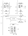
- FIG. It is a figure which shows the communication procedure between a 1st communication apparatus and the monitoring part as a proxy of a 2nd communication apparatus.
- FIG. 4 is a diagram showing a communication procedure between a second communication device and a monitoring unit acting as a proxy for the first communication device; It is a figure which shows the production
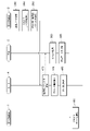
- FIG. 10 is a diagram showing the establishment of seamless OPC UA communication
- Client#1 For communication between Client#1 and Server#1, Client#1 sends a request to Server#2, which receives it. Then, Client#2 is created as a proxy (that is, OPC UA application) of Client#1, and the request is transferred to Server#1. Responses are also forwarded in reverse order.
- connection configuration of a general communication monitoring system is configured by connecting Client #1 and Server #1 without creating Client #2 as a proxy for Client #1. be.
- FIG. 2A An embodiment of the basic configuration of the communication monitoring system in FIG. 1A is as shown in FIG. 2A. That is, the communication monitoring system is provided for monitoring communication between the first communication device 1 and the second communication device 2 and includes a monitoring system body 5 including a monitoring section 3 and a router section 4 .
- the monitoring unit 3, the router unit 4, and the network connecting them may be virtually realized in one computer.
- Software that virtually implements these functions includes, for example, KVM (Kernel-based Virtual Machine).
- the monitoring unit 3 and the router unit 4 may be implemented in different computers.
- the monitoring unit 3 is a monitoring device and the router unit 4 is a router.
- the network between the monitoring unit 3 and the router unit 4 is also an entity.
- the first communication device 1, the second communication device 2, and the monitoring unit 3 can communicate only through the router unit 4. However, as another example, they can communicate without the router unit 4. may
- the first communication device 1 and the second communication device 2 are devices connected to an industrial control network.
- the first communication device 1 may be the OPC server described above (that is, Server #1 described above), and the second communication device 2 may be an OPC client such as SCADA (that is, Client #1 described above).
- the first communication device 1 may be an OPC client such as SCADA (that is, Client #1 described above)
- the second communication device 2 may be an OPC server (that is, Server #1 described above).
- the second communication device 2 may be a controller (for example, PLC) that controls an actuator.
- the first communication device 1 has a network interface 11, a memory 12, and a control section 13.
- a network interface 11 is an interface circuit for communicating with the router section 4 via the LAN 51 .
- the network interface 11 is assigned P1 as an IP address.
- the memory 12 is a non-transitional material storage medium, and includes RAM, ROM, flash memory, and the like.
- RAM is rewritable volatile memory
- ROM is non-rewritable non-volatile memory
- flash memory is rewritable non-volatile memory.
- a program executed by the control unit 13 is recorded in the ROM or flash memory.
- Key information 12a of the first communication device 1 is recorded in the flash memory.
- the key information 12a consists of a secret key SK1, public keys PK1 and PK3, and common keys CK1 and CK2.
- the secret key SK1 may be stored in a TPM (Trusted Platform Module) so that it cannot be read from the outside.
- TPM Truste Module
- the secret key of the first communication device 1 is SK1 and its public key is PK1.
- the public key PK3 corresponds to the secret key SK3 of the monitoring unit 3, and the public key PK1 corresponding to the secret key SK1 is stored in the monitoring unit 3.
- the certificate C1 is recorded in the memory 12.
- This certificate C1 is an electronic certificate that proves the legitimacy of the first communication device 1 .
- the certificate C1 may contain the IP address of the first communication device 1, may contain the public key PK1, or may contain other data identifying the first communication device 1. may be
- the control unit 13 is an arithmetic circuit that reads a program from a ROM or flash memory and performs the processing described later.
- the control unit 13 uses the RAM as a work area and uses the data in the ROM and flash memory in the later-described processing.
- the control unit 13 may acquire signals from an input device and a sensor (not shown) and control a display device and an industrial actuator (for example, a robot) (not shown).
- the processing performed by the control unit 13 will be described as being performed by the first communication device 1 for the sake of simplicity.
- the second communication device 2 has a network interface 21, a memory 22, and a control section 23.
- a network interface 21 is an interface circuit for communicating with the router section 4 via the LAN 52 .
- P2 is assigned to the network interface 21 as an IP address.
- the memory 22 is a non-transitional material storage medium, and includes RAM, ROM, flash memory, and the like.
- a program executed by the control unit 23 is recorded in the ROM or flash memory.
- Key information 22a of the second communication device 2 is recorded in the flash memory.
- the key information 22a consists of a secret key SK2, public keys PK2 and PK3, and common keys CK1 and CK2.
- the secret key of the second communication device 2 is SK2 and its public key is PK2.
- the private key SK2 may be stored in a TPM (Trusted Platform Module) so that it cannot be read from the outside.
- the public key PK3 corresponds to the public key of the monitoring unit 3, and the public key PK2 corresponding to the secret key SK2 is held in the monitoring unit 3.
- the certificate C2 is recorded in the memory 22.
- This certificate C2 is an electronic certificate that proves the legitimacy of the second communication device 2 .
- the certificate C2 may contain the IP address of the second communication device 2, may contain the public key PK2, or may contain other data identifying the second communication device 2. may be
- the control unit 23 is an arithmetic circuit that reads a program from the ROM or flash memory and performs the processing described later.
- the control unit 23 uses the RAM as a work area and uses the data in the ROM and flash memory in the later-described processing.
- the control unit 23 may acquire signals from an input device and a sensor (not shown) and control a display device and an industrial actuator (for example, a robot) not shown.
- the processing performed by the control unit 23 will be described as being performed by the second communication device 2 for the sake of simplicity.
- the monitoring unit 3 has a memory 35.
- the memory 35 is a non-transitional physical storage medium, and includes RAM, ROM, flash memory, and the like.
- a program executed by a control unit (not shown) is recorded in the ROM or flash memory.
- Key information 35a and 35b of the monitoring unit 3 is recorded in the flash memory.
- the key information 35a consists of a private key SK3, public keys PK3 and PK1, and common keys CK1 and CK2.
- the private key of the monitoring unit 3 is SK3 and its public key is PK3.
- the private key SK3 may be stored in a TPM (Trusted Platform Module) so that it cannot be read from the outside.
- the key information 35 a is used for communication with the first communication device 1 .
- the key information 35 a is used to act as a proxy for the second communication device 2 when the monitoring unit 3 communicates with the first communication device 1 .
- the public key PK1 is the public key of the first communication device 1, and the public key PK3 corresponding to the secret key SK3 is held in the first communication device 1.
- the key information 35b consists of a secret key SK3, public keys PK3 and PK2, and common keys CK1 and CK2.
- the private key of the monitoring unit 3 is SK3 and its public key is PK3.
- the key information 35b is used for communication with the second communication device 2.
- FIG. The key information 35 b is used to act as a proxy for the first communication device 1 when the monitoring unit 3 communicates with the second communication device 2 .
- the public key PK2 corresponds to the secret key of the second communication device 2, and the public key PK3 corresponding to the secret key SK3 is held in the second communication device 2.
- the common keys CK1 and CK2 are held by the first communication device 1, the monitoring unit 3, and the second communication device 2.
- the certificate C31 is an electronic certificate for the second communication device 2 to certify that the monitoring unit 3 is a legitimate communication partner. By passing the certificate C31 to the second communication device 2 by the monitoring unit 3, it is assumed that the second communication device 2 is communicating with the first communication device 1.
- the certificate C31 may contain the IP address of the first communication device 1, may contain the public key PK3, and the second communication device 2 may confirm that the monitoring unit 3 is a valid communication partner. Other data may be included to identify the
- the certificate C32 is data for the first communication device 1 to prove that the monitoring unit 3 is a legitimate communication partner. By passing the certificate C32 to the first communication device 1 by the monitoring unit 3, it is assumed that the first communication device 1 is communicating with the second communication device 2.
- the certificate C32 may contain the IP address of the second communication device 2, may contain the public key PK3, and the first communication device 1 may confirm that the monitoring unit 3 is an authorized communication partner.
- Other data may be included to identify the
- the router section 4 has network interfaces 41 and 42 and a memory 45 .
- Network interface 41 is an interface circuit for communicating with first communication device 1 via LAN 51 .
- Network interface 42 is an interface circuit for communicating with second communication device 2 via LAN 52 .
- IP address can be assigned to each network interface of the router unit 4, and P1, P2, P31, and P32 are assigned to the network interfaces 11, 21, 41, and 42, respectively.
- the memory 45 is a non-transitional material storage medium, and includes RAM, ROM, flash memory, and the like.
- the structure of the OPC UA server/client and OPC UA proxy is as follows.
- the arrow between Client #1 and Monitoring System is a request packet, and the character string above the arrow is the type of request packet for OPC UA communication.
- the request packet sent from Client #1 to the Monitoring System is received by the Monitoring System, but the Monitoring System changes the destination and transfers it to Server #1.
- the first communication device 1 creates a request packet addressed to the second communication device 2 in step 110 .
- a request packet is a packet requesting a reply in communication from the first communication device 1 to the second communication device 2 .
- connection request, confirmation request, disconnection request, certificate request, public key request are request packets.
- the destination IP address of this request packet is P31, and the source IP address is P1.
- the first communication device 1 then transmits this request packet from the network interface 11 to the LAN 51 in step 110 .
- the router unit 4 receives this packet via the network interface 41.
- the router section 4 rewrites the destination address of the packet in step 405 . Specifically, since the destination IP address and source IP address before conversion are P31 and P1, respectively, the destination IP address and source IP address are rewritten to P2 and P32, respectively.
- the packet whose destination address has been rewritten is transmitted from the network interface 42 to the LAN 52 in step 410, the packet whose destination address and source address have been rewritten to P2 and P32.
- the packets thus transmitted are received by the second communication device 2 via the network interface 21 .
- the second communication device 2 Upon receiving this packet, the second communication device 2 performs processing according to the content of the transmission data and creates a response packet.
- the destination IP address of this response packet is P32, and the source IP address is P2.
- the second communication device 2 then transmits this response packet from the network interface 21 to the LAN 52 in step 310 .
- the router unit 4 receives this packet via the network interface 42.
- the router section 4 rewrites the destination address of the packet in step 415 . Specifically, since the destination IP address and source IP address before conversion are P32 and P2, respectively, the destination IP address and source IP address are rewritten to P1 and P31, respectively.
- the router section 4 transmits the packet with the destination address and source address rewritten to P1 and P31 from the network interface 41 to the LAN 51. Packets transmitted in this way are received by the first communication device 1 via the network interface 11 .
- the router unit 4 can transmit packets on behalf of the second communication device.
- the second communication device 2 creates a request packet addressed to the first communication device 1 in step 210 .
- the destination IP address of this request packet is P32, and the source IP address is P2.
- the second communication device 2 then transmits this request packet from the network interface 21 to the LAN 52 in step 210 .
- the router unit 4 receives this packet via the network interface 42. Upon receiving this packet, the router unit 4 rewrites the destination address of the packet in step 425 . Specifically, since the destination IP address and source IP address before conversion are P32 and P2, respectively, the destination IP address and source IP address are rewritten to P1 and P31, respectively.
- the router unit 4 transmits the packet with the destination address and source address rewritten to P1 and P31 from the network interface 41 to the LAN 51. Packets transmitted in this way are received by the first communication device 1 via the network interface 11 .
- the first communication device 1 Upon receiving this packet, the first communication device 1 performs processing according to the contents of the transmission data and creates a response packet.
- the destination IP address of this response packet is P31, and the source IP address is P1.
- the first communication device 1 then transmits this response packet from the network interface 11 to the LAN 51 in step 320 .
- the router unit 4 receives this packet via the network interface 41.
- the router section 4 rewrites the destination address of the packet in step 435 . Specifically, since the destination IP address and source IP address before conversion are P31 and P1, respectively, the destination IP address and source IP address are rewritten to P2 and P32, respectively.
- the router unit 4 transmits the packet with the destination address and source address rewritten to P2 and P32 from the network interface 42 to the LAN 52.
- the packets thus transmitted are received by the second communication device 2 via the network interface 21 .
- the router unit 4 can transmit packets on behalf of the first communication device.
- the conversion table 45a in the memory 45 is referenced when the router unit 4 rewrites the destination IP address and source IP address of the packet. Specifically, in the conversion table 45a, when the destination IP address of a received packet is P31 and the source IP address is P1, the destination IP address is set to P2 and the source IP address is set to P32. ing. The conversion table 45a describes that when the destination IP address of the received packet is P32 and the source IP address is P2, the destination IP address is P1 and the source IP address is P31.
- the router unit 4 may also rewrite the endpoint description in the payload of the packet to the same value as the rewritten source IP address.
- the endpoint description is an indicator that defines the return destination in OPC UA.
- the first communication device 1 has private key SK1, public key PK1, and certificate C1 in memory 12
- the second communication device 2 has private key SK2, public key SK2, and certificate C1 in memory 22. It has public key PK2 and certificate C2, and monitoring unit 3 has private key SK3, public key PK3, and certificates C31 and C32 in memory .
- FIGS. 4A and 4B show a case where the second communication device 2 initiates the session, but the first communication device 1 may initiate the session. In the latter case, the roles of the first communication device 1 and the second communication device 2 are switched in FIGS. 4A and 4B.
- the second communication device 2 transmits a packet containing the certificate C2 and the public key PK2 in the memory 22 to the router section 4 of the monitoring system main body 5. Then, the monitoring system body 5 receives, verifies, and stores this packet in step 810 . Specifically, the router unit 4 receives this packet and transfers it to the monitoring unit 3. The monitoring unit 3 verifies the legitimacy of the second communication device 2 using the certificate C2 in the packet, PK2 is recorded in the key information 35 b of the memory 35 .
- the monitoring system body 5 replaces the certificate C2 and public key PK2 in the payload of this packet with the certificate C32 and public key PK3 in the memory 35, respectively, and transmits them to the first communication device 1.
- the router unit 4 requests the monitoring unit 3 for the certificate C32 and the public key PK3.
- the router section 4 receives this certificate C32 and public key PK3 and performs the replacement described above.
- step 610 the first communication device 1 receives this packet transmitted from the monitoring system body 5, verifies the legitimacy of the monitoring unit 3 using the certificate C32 in the packet, and obtains the public key PK3. It is recorded in the key information 12 a of the memory 12 .
- the first communication device 1 generates a random number NONCE1, and in step 620 encrypts this random number NONCE1 with the public key PK3 in the key information 12a. Furthermore, at step 625 , the first communication device 1 transmits a packet containing the certificate C 1 and public key PK 1 in the memory 12 and the encrypted random number NONCE 1 to the router section 4 of the monitoring system main body 5 .
- the monitoring system body 5 then receives, verifies, and stores this packet in step 820 .
- the router unit 4 receives this packet and transfers it to the monitoring unit 3.
- the monitoring unit 3 verifies the legitimacy of the first communication device 1 using the certificate C1 in the packet, PK1 is recorded in the key information 35 a of the memory 35 .
- the monitoring unit 3 of the monitoring system main body 5 decrypts the random number NONCE1 in the payload of this packet with the secret key SK3 in the memory 35 and saves the decrypted random number NONCE1 in the memory 35 at step 825 . Furthermore, in step 830, the monitoring unit 3 encrypts the decrypted random number NONCE1 with the public key PK2 in the memory 35, and transfers the encrypted random number NONCE1, the certificate C31 and the public key PK3 in the memory 35 to the router. Send to Part 4.
- the router section 4 of the monitoring system main body 5 converts the certificate C1, the public key PK1, and the encrypted random number NONCE1 in the packet received at step 820 to the certificate C31 received from the monitoring section 3. , with the public key PK3 and the encrypted random number NONCE1. Then, the packet after replacement is transmitted to the second communication device 2 .
- the second communication device 2 receives this packet transmitted from the monitoring system body 5, verifies the legitimacy of the monitoring unit 3 using the certificate C31 in the packet, and obtains the public key PK3. It is recorded in the key information 22 a of the memory 22 . Subsequently, the second communication device 2 decrypts the random number NONCE1 in the received packet with the secret key SK2 and records it in the memory 22 at step 720 .
- the second communication device 2 generates a random number NONCE2 in step 725 of FIG. 4B, and encrypts this random number NONCE2 with the public key PK3 in the key information 22a in step 730. Further, at step 735 , the second communication device 2 transmits a packet containing the certificate C 2 and public key PK 2 in the memory 22 and the encrypted random number NONCE 2 to the router section 4 of the monitoring system main body 5 .
- the monitoring system body 5 then receives, verifies, and stores this packet in step 840 .
- the router unit 4 receives this packet and transfers it to the monitoring unit 3.
- the monitoring unit 3 verifies the legitimacy of the second communication device 2 using the certificate C2 in the packet, PK2 is recorded in the key information 35 b of the memory 35 .
- the monitoring unit 3 decrypts the random number NONCE2 in the payload of this packet with the private key SK3 in the memory 35, and stores the decrypted random number NONCE2 in the memory 35. Furthermore, in step 850, the monitoring unit 3 encrypts the decrypted random number NONCE2 with the public key PK1 in the memory 35, and transfers the encrypted random number NONCE2, the certificate C32 and the public key PK3 in the memory 35 to the router. Send to Part 4.
- the router section 4 of the monitoring system main body 5 converts the certificate C2, the public key PK2, and the encrypted random number NONCE2 in the packet received at step 840 to the certificate C32 received from the monitoring section 3. , with the public key PK3 and the encrypted random number NONCE2. Then, the packet after replacement is transmitted to the first communication device 1 .
- the first communication device 1 receives this packet transmitted from the monitoring system body 5, verifies the legitimacy of the monitoring unit 3 using the certificate C32 in the packet, and obtains the public key PK3. It is recorded in the key information 22 a of the memory 22 . Subsequently, the first communication device 1 decrypts the random number NONCE2 in the received packet with the secret key SK1 and records it in the memory 12 at step 635 .
- both the decrypted random number NONCE1 and random number NONCE2 are stored in the first communication device 1, the second communication device 2, and the monitoring system body 5, respectively.
- Common keys CK1 and CK2 are generated based on these random numbers NONCE1 and NONCE2, respectively.
- step 640 the first communication device 1 generates a common key CK1 from the random number NONCE1 and records it in the key information 12a of the memory 12, and further in step 645, generates a common key CK1 from the random number NONCE2.
- CK2 is generated and recorded in the key information 12a.
- step 740 the second communication device 2 generates a common key CK1 from the random number NONCE1 and records it in the key information 22a of the memory 22, and in step 745 generates a common key CK2 from the random number NONCE2. and record it in the key information 22a.
- step 860 the monitoring unit 3 of the monitoring system body 5 generates a common key CK1 from the random number NONCE1 and records it in the key information 35a and 35b of the memory 35.
- a common key CK2 is generated and recorded in the key information 35a, 35b.
- the algorithm for generating the common key CK1 from the random number NONCE1 is the same for the first communication device 1, the second communication device 2, and the monitoring unit 3. Further, the algorithm for generating the common key CK1 from the random number NONCE1 is such that if the value of the random number NONCE1 is different, the value of the common key CK1 is also different. Therefore, in the first communication device 1, the second communication device 2, and the monitoring unit 3, the common key CK1 having the same value is generated from the random number NONCE1 having the same value using the same algorithm.
- the algorithm for generating the common key CK2 from the random number NONCE2 is the same for the first communication device 1, the second communication device 2, and the monitoring unit 3. Further, the algorithm for generating the common key CK2 from the random number NONCE2 is such that if the value of the random number NONCE2 is different, the value of the common key CK2 is also different. Therefore, in the first communication device 1, the second communication device 2, and the monitoring unit 3, the common key CK2 having the same value is generated from the random number NONCE2 having the same value using the same algorithm.
- the algorithm for generating the common key CK1 from the random number NONCE1 and the algorithm for generating the common key CK2 from the random number NONCE2 may be the same or different. Since the random number NONCE1 and the random number NONCE2 have different values, the common key CK1 and the common key CK2 also have different values.
- the common key CK1 is used to encrypt and decrypt payloads in packets sent from the first communication device 1 to the second communication device 2 via the monitoring system body 5.
- the common key CK2 is used to encrypt and decrypt the payload in the packet sent from the second communication device 2 to the first communication device 1 via the monitoring system body 5.
- FIG. 1 A case in which a packet is transmitted from the first communication device 1 to the second communication device 2, and the packet is transmitted from the second communication device 2 to the first communication device 1 based on the content of the packet will be described below. Even if the positions of the first communication device 1 and the second communication device 2 are reversed, equivalent processing is realized.
- the first communication device 1 creates transmission data to be transmitted to the second communication device 2, and encrypts the created transmission data.
- the content of the transmission data may be, for example, a command for causing the second communication device 2 to perform a specific operation (for example, controlling an actuator).
- a common key cryptosystem is used for this encryption.
- OPC-UA uses public-key private-key cryptography for exchanging certificates and common keys when opening a communication session, and for exchanging data, a common key created for each session is used.
- a hybrid method that uses a common key cryptosystem is adopted.
- the device on the transmitting side (the first communication device 1 in step 130) encrypts the data (that is, the payload) in the packet to be transmitted using an encryption method according to the procedure defined by the hybrid method.
- the destination of this packet is the second communication device 2 .
- the actual destination IP address of this packet is P31 and the source IP address is P1.
- the router unit 4 receives this packet via the network interface 41. Upon receiving this packet, the router section 4 transfers the packet to the monitoring section 3 in step 450 .
- the monitoring unit 3 Upon receiving this packet, the monitoring unit 3 decrypts the payload of this packet with the common key CK1 in step 340.
- the monitoring unit 3 has two common keys CK1 and CK2. At this time, the monitoring unit 3 uses CK2 as the common key for decryption based on the information that the source IP address of the packet is P1.
- step 345 the monitoring unit 3 records in the memory 35 the plaintext transmission data (that is, communication content) decrypted in the previous step 340 .
- the monitoring unit 3 may notify the operator of the monitoring unit 3 of the abnormality.
- the notification method may be sending an e-mail or activating a notification device (not shown).
- the monitoring unit 3 may determine whether or not there is an abnormality in the contents of the transmission data, for example, by determining whether or not a command included in the transmission data corresponds to a predetermined abnormal command.
- the procedure from step 450 to step 455 and the procedure from step 450 to step 340 are performed by parallel processing.
- the router section 4 rewrites the destination address of the packet. Specifically, since the destination IP address and source IP address before conversion are P31 and P1, respectively, the destination IP address and source IP address are rewritten to P2 and P32, respectively.
- the router unit 4 transmits the packet with the destination address and the source address rewritten to P2 and P32 from the network interface 42 to the LAN 52 .
- the packets thus transmitted are received by the second communication device 2 via the network interface 21 .
- the second communication device 2 Upon receiving this packet, the second communication device 2 uses the common key CK1 to decrypt the payload in the packet in step 220. As a result, the second communication device 2 acquires plaintext transmission data.
- the second communication device 2 performs processing according to the content of the transmission data. For example, if the transmission data contains a control command, the actuator is controlled according to that command.
- the second communication device 2 creates return data in step 240 of FIG. For example, if the transmission data includes a control command and the second communication device 2 controls the actuator according to the control command in step 230, the second communication device 2 includes data of the control result of the actuator in the return data. .
- the second communication device 2 encrypts the return data created in step 240 using the common key CK2.
- the common key CK2 used at this time is created when the session is updated as described above, and is shared among the first communication device 1, the second communication device 2, and the monitoring unit 3.
- step 260 the second communication device 2 creates a packet with the data encrypted in the previous step 250 as payload, the source address as P2, and the destination address as P32, and sends the packet from network interface 21. to the LAN 52.
- the destination of this packet is the first communication device 1.
- the actual destination IP address is P1
- the source IP address is as described above.
- the router unit 4 receives this packet via the network interface 42. Upon receiving this packet, the router section 4 rewrites the destination address of the packet in accordance with the conversion table 45a in step 475.
- FIG. Specifically, since the destination IP address before conversion is P1, the destination IP address is rewritten to P31 as shown in FIG. 2A.
- the router unit 4 transmits the packet with the destination address and the source address rewritten to P1 and P31 from the network interface 41 to the LAN51. Packets transmitted in this way are received by the first communication device 1 via the network interface 11 .
- the first communication device 1 Upon receiving this packet, the first communication device 1 decrypts the payload in the packet at step 150 using the common key CK2. As a result, the first communication device 1 acquires the plaintext return data.
- This packet is sent to the monitoring unit 3 in the router unit 4.
- the packet is transferred to the monitoring section 3 by the router section 4 .
- the monitoring unit 3 Upon receiving this packet, the monitoring unit 3 decrypts the payload of this packet with the common key CK2 in step 360.
- the monitoring unit 3 has two common keys CK1 and CK2.
- the monitoring unit 3 uses CK2 as the common key for decryption. This decryption yields plaintext return data.
- step 365 the monitoring unit 3 records in the memory 35 the plaintext return data (that is, communication content) decrypted in the previous step 360.
- the monitoring section 3 may notify the operator of the monitoring section 3 of the abnormality, as in step 345 .
- the procedure from step 470 to step 475 and the procedure from step 450 to step 360 are performed by parallel processing.
- This common key CK2 is an encryption key shared by the first communication device 1, the second communication device 2, and the monitoring unit 3.
- the common key CK ⁇ b>2 used at this time is created when the session is updated and shared among the first communication device 1 , the second communication device 2 and the monitoring unit 3 .
- the monitoring unit 3 is the source of the request packet based on the reception of the request packet addressed to the second communication device 2 from the first communication device 1 in the process shown in FIG. 3A.
- a response packet is transmitted to the first communication device 1 .
- the monitoring unit 3 sends the second communication device 2, which is the source of the request packet, based on the reception of the request packet addressed to the first communication device 1 from the second communication device 2.
- Send a response packet that is, when the monitoring unit 3 receives data that requires a response, such as a request packet, it responds to the first communication device 1 as a proxy for the second communication device 2 in the process of FIG. 3A, and responds to the first communication device 1 in the process of FIG. 3B. Responding to the second communication device 2 on behalf of device 1 .
- the monitoring unit 3 does not decode the payload of the packet that needs to reach the second communication device 2 among the packets transmitted from the first communication device 1 to the second communication device 2. is transferred to the second communication device 2 as it is. Also, in the process of FIG. 6, the monitoring unit 3 does not decode the payload of the packet that needs to reach the first communication device 1 among the packets transmitted from the second communication device 2 to the first communication device 1. is transferred to the first communication device 1 as it is.
- the monitoring unit 3 processes communication setting and communication confirmation packets between the monitoring unit 3 and the communication devices 1 and 2 as shown in FIGS. 3A and 3B, and data communication packets as shown in FIGS. 6, the monitoring unit 3 is used as a relay point.
- the first communication device 1 and the second communication device 2 do not communicate directly, but communicate via the router section 4.
- the first communication device 1 transmits a packet addressed to the second communication device 2 , and the packet is sent to the monitoring unit 3 in the router unit 4 .
- encryption is performed with a key shared by the first communication device 1 and the monitoring section 3 so that the encrypted data from the first communication device 1 can be decrypted in the monitoring section 3 .
- the address of the destination is converted (steps 450, 455), and the packet that reaches the monitoring unit 3 is decrypted using the key shared by the first communication device 1 and the monitoring unit 3 and recorded (step 345). ).
- the second communication device 2 is the controller described above, since the controller is designed to follow even dangerous instructions, it is possible to monitor the communication contents of the control network to see if any dangerous instructions are being sent to the controller. Desired. If a malicious intruder intrudes into the authorized first communication device 1 capable of sending instructions to the controller and sends malicious instructions, there is a risk of an accident occurring. To monitor such communication, it is necessary to interpret the content of the payload in the packet. I can't. The monitoring unit 3 and router unit 4 solve this problem.
- the information monitored by the monitoring unit 3 be saved while avoiding attacks even if an attacker intrudes into the control network.
- the contents of encrypted communication can be monitored and recorded by the monitoring section 3 and the router section 4 without the existence of the monitoring section 3 being known.
- a common key CK ⁇ b>1 used for encryption of the first communication device 1 is shared by the first communication device 1 , the second communication device 2 , and the monitoring unit 3 . Therefore, even if a communication packet from the first communication device 1 reaches the second communication device 2 directly, it can be decoded.
- the encrypted packet sent from the first communication device 1 to the second communication device 2 can be monitored only after passing through the monitoring unit 3 and the router unit 4, and can be decrypted by the second communication device 2. become. Not only the first communication device 1 and the second communication device 2, but also when performing encrypted communication between three or more communication devices, all of them go through the router unit 4 and are encrypted and decrypted by all the communication devices and the monitoring unit 3. are shared between the monitoring unit 3 and the communication device.
- the router unit 4 functions as an acquisition unit by executing steps 450 and 455, functions as a transfer unit by executing steps 460 and 465, and functions as a transfer unit by executing steps 405 and 410. It functions as a request packet transfer part.
- the monitoring unit 3 functions as a decoding unit by executing step 340 and functions as a recording unit by executing step 345 .
- the common key CK1 corresponds to the first encryption key
- the common key CK1 corresponds to the first decryption key
- the common key CK2 corresponds to the second encryption key
- the common key CK2 corresponds to the second decryption key.
- the OPC UA proxy has a static FromTo table (static table) for routing. Such a static table has a merit that processing overhead is small because FromTo is uniquely determined.
- the router unit 4 of the above embodiment corresponds to the OPC UA proxy, and the conversion table 45a corresponds to the static table. In other words, specification of route information for packets between the first communication device 1, the second communication device 2, and the router unit 4 is realized by the conversion table 45a.
- it since it is static, it is necessary to manually set FromTo, so the more OPC UA proxies to pass through, the more time and effort it takes to set it. In addition, since it is necessary to set manually, there is a disadvantage that human errors such as setting errors are likely to occur.
- specifying route information using a URL can be done as follows.
- specifying from the OPC UA client simply specify the IP address + port number of the OPC UA proxy for the resource part, and specify the IP address + port number of the OPC UA server for the identifier.
- OPC UA client #1 eg, first communication device 1
- OPC UA server #1 eg, second communication device 2
- OPC UA proxy eg, router unit 4
- this URL information is sent from OPC UA client #1 to the OPC UA proxy (Monitoring System in FIG. 7) be done. Then, based on the description in this URL, the OPC UA proxy forwards the packet sent from the OPC UA client #1 to the OPC UA proxy to the OPC UA server #1, and as a response to this packet, the OPC UA server Transfer the packet sent from #1 to the OPC UA proxy to OPC UA client #1.
- URL is an abbreviation for Uniform Resource Locator, a method of locating a resource by describing its primary access mechanism (for example, its "location" on the network) in addition to identifying the resource.
- URI Uniform Resource Identifier
- URL is an abbreviation for Uniform Resource Identifier, and is a concise character string for identifying abstract or physical resources.
- the URL has the syntax of "protocol” + "resource (remote host)” + "identifier”.
- a protocol specifies a convention name such as HTTP or MQTT. Since the resource indicates a remote host, specify the domain name and IP address. Separate the port numbers with a colon (:) if necessary.
- An identifier is generally used as a unique identifier that identifies a position within a connection destination. In the case of OPC UA TCP communication, the protocol specifies "opc.tcp". Resources specify domain names and IP addresses. Separate the port numbers with a colon (:) if necessary.
- the destination routing method can be set without using a static FromTo table (static table).
- a realization method using routing that enables communication between the communication device 1 and the second communication device 2 may also be used.
- Resources specify domain names and IP addresses. Separate the port numbers with a colon (:) if necessary.
- the request packet and the response packet are the forward packet and the backward packet in one round-trip communication.
- the request and response packets may be a forward packet followed by a subsequent backward packet in a series of sessions consisting of multiple round trips. This is because even in the latter case, the response packet is generated due to the transmission of the request packet.
- Modification 3 In the above embodiment, one-to-one communication between the first communication device 1 and the second communication device 2 is illustrated. However, other than this type of communication, the communication monitoring system can also be applied to a form in which two or more communication devices communicate with the same number of communication devices on a one-to-one basis. In this case, communication partners are fixedly determined for two or more communication devices.
- the monitoring unit 3 includes key information 35 a for communicating with the first communication device 1 and key information 35 b for communicating with the second communication device 2 .
- it may have a single key information for communicating with the first communication device 1 and the second communication device 2 .
- the monitoring unit 3 may transmit the data to be recorded in the memory 35 in steps 345 and 365 to a recording device on another network different from the control network.
- the recording unit records the data thus transmitted on the storage medium.
- the control unit 13 of the first communication device 1, the control unit 23 of the second communication device 2, and the monitoring unit 3 respectively encrypt and decrypt data.
- a device for example, a TPM security module
- the control units 13, 23 and the monitoring unit 3 performs encryption and decryption processing. It can be like this.
- both the first encryption key and the first decryption key are the same common key CK1.
- the first encryption key and the first decryption key may be different.
- the first encryption key may be a certain public key
- the first decryption key may be a private key corresponding to the public key.
- the key pair consisting of the encryption key and the public key may be generated from the random number NONCE1 common to the first communication device 1, the second communication device 2, and the monitoring unit 3.
- the second encryption key and the second decryption key may be a public key
- the second decryption key may be a private key corresponding to the public key.
- OPC UA is a new communication technology in the industrial world.
- the German government introduced it as a next-generation communication technology that will realize Industry 4.0.
- OPC UA is highly likely to become a standard in the industrial world in the future.
- the present invention is deployed at the boundary of a zoned network and used to monitor data flowing over an encrypted network, data directionality, and API parameters.
Landscapes
- Engineering & Computer Science (AREA)
- Computer Networks & Wireless Communication (AREA)
- Signal Processing (AREA)
- Computer Security & Cryptography (AREA)
- Theoretical Computer Science (AREA)
- Physics & Mathematics (AREA)
- General Physics & Mathematics (AREA)
- General Engineering & Computer Science (AREA)
- Bioethics (AREA)
- General Health & Medical Sciences (AREA)
- Computer Hardware Design (AREA)
- Software Systems (AREA)
- Health & Medical Sciences (AREA)
- Automation & Control Theory (AREA)
- Quality & Reliability (AREA)
- Data Exchanges In Wide-Area Networks (AREA)
Priority Applications (2)
| Application Number | Priority Date | Filing Date | Title |
|---|---|---|---|
| JP2023533149A JPWO2023282263A1 (https=) | 2021-07-08 | 2022-07-05 | |
| US18/577,415 US20240251266A1 (en) | 2021-07-08 | 2022-07-05 | Communication monitoring system in control network |
Applications Claiming Priority (2)
| Application Number | Priority Date | Filing Date | Title |
|---|---|---|---|
| JP2021113226 | 2021-07-08 | ||
| JP2021-113226 | 2021-07-08 |
Publications (1)
| Publication Number | Publication Date |
|---|---|
| WO2023282263A1 true WO2023282263A1 (ja) | 2023-01-12 |
Family
ID=84800703
Family Applications (1)
| Application Number | Title | Priority Date | Filing Date |
|---|---|---|---|
| PCT/JP2022/026731 Ceased WO2023282263A1 (ja) | 2021-07-08 | 2022-07-05 | 制御ネットワークにおける通信監視システム |
Country Status (3)
| Country | Link |
|---|---|
| US (1) | US20240251266A1 (https=) |
| JP (1) | JPWO2023282263A1 (https=) |
| WO (1) | WO2023282263A1 (https=) |
Families Citing this family (1)
| Publication number | Priority date | Publication date | Assignee | Title |
|---|---|---|---|---|
| EP4120110A1 (en) * | 2021-07-12 | 2023-01-18 | Abb Schweiz Ag | Opc ua-based anomaly detection and recovery system and method |
Citations (2)
| Publication number | Priority date | Publication date | Assignee | Title |
|---|---|---|---|---|
| JP2018073397A (ja) * | 2016-10-27 | 2018-05-10 | 国立大学法人 名古屋工業大学 | 通信装置 |
| JP2020022165A (ja) * | 2018-08-02 | 2020-02-06 | シーメンス アクチエンゲゼルシヤフトSiemens Aktiengesellschaft | 自動化された公開鍵基盤の初期設定 |
-
2022
- 2022-07-05 WO PCT/JP2022/026731 patent/WO2023282263A1/ja not_active Ceased
- 2022-07-05 JP JP2023533149A patent/JPWO2023282263A1/ja active Pending
- 2022-07-05 US US18/577,415 patent/US20240251266A1/en active Pending
Patent Citations (2)
| Publication number | Priority date | Publication date | Assignee | Title |
|---|---|---|---|---|
| JP2018073397A (ja) * | 2016-10-27 | 2018-05-10 | 国立大学法人 名古屋工業大学 | 通信装置 |
| JP2020022165A (ja) * | 2018-08-02 | 2020-02-06 | シーメンス アクチエンゲゼルシヤフトSiemens Aktiengesellschaft | 自動化された公開鍵基盤の初期設定 |
Non-Patent Citations (1)
| Title |
|---|
| HONDA, TOSHIAKI: "OPC UA to support smart factories - Future role and direction of progress", INSTRUMENTATION CONTROL ENGINEERING, KOGYO GIJUTSU-SHA, TOKYO, JP, vol. 62, no. 10, 19 September 2019 (2019-09-19), JP , pages 59 - 62, XP009542794, ISSN: 0368-5780 * |
Also Published As
| Publication number | Publication date |
|---|---|
| US20240251266A1 (en) | 2024-07-25 |
| JPWO2023282263A1 (https=) | 2023-01-12 |
Similar Documents
| Publication | Publication Date | Title |
|---|---|---|
| US11477037B2 (en) | Providing forward secrecy in a terminating SSL/TLS connection proxy using ephemeral Diffie-Hellman key exchange | |
| CN111801926B (zh) | 用于公开至少一个密码学密钥的方法和系统 | |
| JP4101839B2 (ja) | セッション制御サーバ及び通信システム | |
| JP4081724B1 (ja) | クライアント端末、中継サーバ、通信システム、及び通信方法 | |
| EP3044641B1 (en) | Restricting communications in industrial control | |
| JP5607655B2 (ja) | 非暗号化ネットワーク動作解決策 | |
| KR102095893B1 (ko) | 서비스 처리 방법 및 장치 | |
| JP4006403B2 (ja) | ディジタル署名発行装置 | |
| EP3216163B1 (en) | Providing forward secrecy in a terminating ssl/tls connection proxy using ephemeral diffie-hellman key exchange | |
| US20170317836A1 (en) | Service Processing Method and Apparatus | |
| CN110191052B (zh) | 一种跨协议网络传输方法及系统 | |
| JP2010539839A (ja) | サーバ基盤移動インターネットプロトコルシステムにおけるセキュリティ方法 | |
| Hossain et al. | P-hip: A lightweight and privacy-aware host identity protocol for internet of things | |
| JP2021111858A (ja) | 制御ネットワークにおける通信監視システム | |
| Farinacci et al. | Locator/ID separation protocol (LISP) data-plane confidentiality | |
| WO2016134631A1 (zh) | 一种OpenFlow报文的处理方法及网元 | |
| WO2023282263A1 (ja) | 制御ネットワークにおける通信監視システム | |
| JP2005236728A (ja) | サーバ装置、要求発行機器、要求受諾機器、通信システム及び通信方法 | |
| CN112205018B (zh) | 监控网络中的加密连接的方法、设备 | |
| JP3714850B2 (ja) | ゲートウェイ装置、接続サーバ装置、インターネット端末、ネットワークシステム | |
| JP6762735B2 (ja) | 端末間通信システム及び端末間通信方法及びコンピュータプログラム | |
| CN106464684B (zh) | 业务处理方法及装置 | |
| JP2015027031A (ja) | 通信システム | |
| JP4757088B2 (ja) | 中継装置 | |
| CN113890844A (zh) | 一种ping命令优化的方法、装置、设备及可读介质 |
Legal Events
| Date | Code | Title | Description |
|---|---|---|---|
| 121 | Ep: the epo has been informed by wipo that ep was designated in this application |
Ref document number: 22837677 Country of ref document: EP Kind code of ref document: A1 |
|
| WWE | Wipo information: entry into national phase |
Ref document number: 2023533149 Country of ref document: JP |
|
| NENP | Non-entry into the national phase |
Ref country code: DE |
|
| WWE | Wipo information: entry into national phase |
Ref document number: 18577415 Country of ref document: US |
|
| 122 | Ep: pct application non-entry in european phase |
Ref document number: 22837677 Country of ref document: EP Kind code of ref document: A1 |