WO2023281805A1 - Communication system, control system, and communication method - Google Patents
Communication system, control system, and communication method Download PDFInfo
- Publication number
- WO2023281805A1 WO2023281805A1 PCT/JP2022/007885 JP2022007885W WO2023281805A1 WO 2023281805 A1 WO2023281805 A1 WO 2023281805A1 JP 2022007885 W JP2022007885 W JP 2022007885W WO 2023281805 A1 WO2023281805 A1 WO 2023281805A1
- Authority
- WO
- WIPO (PCT)
- Prior art keywords
- unit
- data sets
- data set
- read
- order
- Prior art date
Links
- 238000004891 communication Methods 0.000 title claims abstract description 240
- 238000000034 method Methods 0.000 title description 46
- 239000000872 buffer Substances 0.000 claims abstract description 187
- 230000005540 biological transmission Effects 0.000 claims abstract description 89
- 238000012790 confirmation Methods 0.000 claims description 30
- 238000010295 mobile communication Methods 0.000 claims description 13
- 238000002360 preparation method Methods 0.000 claims description 4
- 238000010586 diagram Methods 0.000 description 15
- 230000008569 process Effects 0.000 description 11
- 238000012545 processing Methods 0.000 description 8
- 210000000707 wrist Anatomy 0.000 description 7
- 230000004044 response Effects 0.000 description 5
- 238000005401 electroluminescence Methods 0.000 description 4
- 230000003287 optical effect Effects 0.000 description 4
- 230000001360 synchronised effect Effects 0.000 description 4
- 230000009471 action Effects 0.000 description 3
- 230000008859 change Effects 0.000 description 3
- 230000004048 modification Effects 0.000 description 3
- 238000012986 modification Methods 0.000 description 3
- 230000000737 periodic effect Effects 0.000 description 3
- 241000699670 Mus sp. Species 0.000 description 2
- 230000001174 ascending effect Effects 0.000 description 2
- 230000003111 delayed effect Effects 0.000 description 2
- 239000012636 effector Substances 0.000 description 2
- 239000004973 liquid crystal related substance Substances 0.000 description 2
- 230000007423 decrease Effects 0.000 description 1
- 230000006870 function Effects 0.000 description 1
- 230000006855 networking Effects 0.000 description 1
- 230000009467 reduction Effects 0.000 description 1
- 230000032258 transport Effects 0.000 description 1
Images


Classifications
-
- H—ELECTRICITY
- H04—ELECTRIC COMMUNICATION TECHNIQUE
- H04L—TRANSMISSION OF DIGITAL INFORMATION, e.g. TELEGRAPHIC COMMUNICATION
- H04L47/00—Traffic control in data switching networks
- H04L47/10—Flow control; Congestion control
- H04L47/34—Flow control; Congestion control ensuring sequence integrity, e.g. using sequence numbers
Definitions
- the present disclosure relates to communication systems, control systems, and communication methods.
- Patent Document 1 discloses a system including a robot, a processing device, a robot controller that controls the robot, a processing device controller that controls the processing device, and a programmable logic controller that generates commands for the robot controller and the processing device controller. disclosed.
- the present disclosure provides a communication system effective for utilizing multiple data sets received via communication in proper order.
- a communication system includes an information addition unit that adds order information to each of a plurality of data sets, a transmission unit that sequentially transmits a plurality of data sets to which the order information is added, and from the transmission unit A receiving unit that sequentially receives a plurality of data sets, an arranging unit that arranges the plurality of data sets received by the receiving unit in a waiting buffer in order based on order information, and a plurality of data sets stored in the waiting buffer and a reading unit that sequentially reads the data in the order in which the data is read.
- a control system includes the communication system described above, a controller that sequentially generates a plurality of command data sets, and a local controller that operates a machine based on the plurality of command data sets, and an information addition unit adds order information to each of the plurality of command data sets generated by the controller, the transmitting unit sequentially transmits the plurality of command data sets to which the order information is added, and the receiving unit transmits the plurality of command data sets.
- the sequence is received, the arranging unit arranges the plurality of command data sets received by the receiving unit in the waiting buffer in the order based on the order information, and the reading unit arranges the plurality of command data sets stored in the waiting buffer.
- the local controller operates the machine based on the plurality of command data sets read by the read section.
- a communication method includes adding order information to each of a plurality of data sets, sequentially transmitting the plurality of data sets to which the order information is added by a transmitting unit, By sequentially receiving a plurality of data sets from the transmitting unit, arranging the plurality of data sets received by the receiving unit in a waiting buffer in an order based on the order information, and a plurality of data stored in the waiting buffer and sequentially reading the set in an arranged order.
- FIG. 1 is a schematic diagram illustrating a communication system
- FIG. 1 is a schematic diagram illustrating the configuration of a robot
- FIG. 3 is a block diagram illustrating functional configurations of a control server and communication devices
- FIG. 3 is a block diagram illustrating functional configurations of a communication device and a local device
- FIG. 3 is a schematic diagram illustrating the storage contents of a receive buffer and the storage contents of a standby buffer
- It is a block diagram which shows the modification of a communication apparatus and a local device.
- FIG. 11 is a block diagram showing a modification of the control server and communication device
- FIG. 11 is a block diagram showing a further modified example of the control server
- 3 is a block diagram illustrating the hardware configuration of a control server and communication devices;
- FIG. 4 is a flow chart illustrating a procedure for generating and transmitting a command data set
- FIG. 10 is a flow chart illustrating an arrangement procedure for multiple command data sets
- FIG. 4 is a flow chart illustrating a communication procedure
- 4 is a flow chart illustrating a local control procedure
- FIG. 10 is a flow chart illustrating an ordering procedure for multiple feedback data sets
- FIG. 4 is a flow chart illustrating a communication procedure
- a communication system 1 shown in FIG. 1 is a system that performs communication of a plurality of data sets between a supply application that supplies a plurality of data sets and a utilization application that uses the supplied plurality of data sets.
- the order of transmission of multiple data sets and the order of reception of multiple data sets may change. For example, an earlier transmitted data set may be received later than a later transmitted data set. Such replacement occurs irregularly. Therefore, when multiple data sets are communicated between the supplying application and the consuming application, the multiple data sets may not be used in the proper order in the consuming application.
- the communication system 1 adds order information to each of the plurality of data sets, sequentially transmits the plurality of data sets to which the order information is added, and sequentially receives the transmitted plurality of data sets. arranging the plurality of data sets received in the waiting buffer in the order based on the order information; and sequentially reading the plurality of data sets stored in the waiting buffer in the arranged order. is configured to
- the communication system 1 is applicable to various systems in which communication is performed between supply applications and utilization applications. In the following, the case where the communication system 1 is applied to the control system 10 will be exemplified in detail.
- the control system 10 includes a communication system 1, a controller 111 that sequentially generates a plurality of command data sets, and a local controller 315 that operates the machine 30 based on the plurality of command data sets.
- the communication system 1 applied to the control system 10 adds order information to each of the plurality of command data sets generated by the controller 111 and sequentially transmits the plurality of command data sets to which the order information is added. , sequentially receiving the plurality of transmitted command data sets, arranging the received plurality of command data sets in a waiting buffer in an order based on the order information, and arranging the plurality of command data sets stored in the waiting buffer sequentially reading in the order in which they are arranged;
- the local controller 315 operates the machine 30 based on command data sets sequentially read by the communication system 1 . In communicating multiple command data sets, controller 111 is the supplying application and local controller 315 is the utilizing application.
- the control system 10 may comprise a plurality of local controllers 315 that respectively operate a plurality of machines 30 and a plurality of controllers 111 that respectively correspond to the plurality of local controllers 315 .
- the machine 30 is a machine that implements actions. Although the type of machine 30 is not particularly limited, two types of machines 30A and 30B are illustrated in FIG.
- the machine 30A is a mobile robot that works on a work while moving. For example, machine 30A has automatic guided vehicle 31 and robot 40 . The automatic guided vehicle 31 is driven by the local controller 315 to move.
- the robot 40 is installed on the unmanned guided vehicle 31.
- the robot 40 is driven by the local controller 315 to carry out work such as transportation, processing, and assembly of the work.
- the robot 40 is, for example, a vertically articulated industrial robot. As shown in FIG. 2 , the robot 40 has a base portion 41 , a turning portion 42 , a first arm 43 , a second arm 44 , a wrist portion 45 and a tip portion 46 .
- the base 41 is installed on the automatic guided vehicle 31 .
- the swivel part 42 is mounted on the base part 41 so as to be rotatable around the vertical axis 51 .
- the robot 40 has a joint 61 that attaches the pivot 42 to the base 41 so as to be rotatable about the axis 51 .
- the first arm 43 is connected to the swivel portion 42 so as to be rotatable about an axis 52 that intersects (for example, is perpendicular to) the axis 51 .
- the robot 40 has a joint 62 that connects the first arm 43 to the pivot 42 so as to be rotatable about the axis 52 .
- An intersection includes being in a twisted relationship, such as a so-called overpass. The same applies to the following.
- the first arm 43 extends from the turning portion 42 along one direction that intersects (for example, orthogonally) the axis 52 .
- the second arm 44 is connected to the end of the first arm 43 so as to be rotatable around an axis 53 parallel to the axis 52 .
- the robot 40 has a joint 63 connecting the second arm 44 to the first arm 43 so as to be rotatable about the axis 53 .
- the second arm 44 includes an arm base 47 extending from the end of the first arm 43 along one direction intersecting (for example, perpendicular to) the axis 53 and an arm further extending from the end of the arm base 47 along the same one direction. and end 48 .
- Arm end 48 is rotatable about axis 54 with respect to arm base 47 .
- Axis 54 intersects (eg, is orthogonal to) axis 53 .
- robot 40 has a joint 64 that connects arm end 48 to arm base 47 such that arm end 48 is rotatable about axis 54 .
- the wrist 45 is connected to the end of the arm end 48 so as to be rotatable about an axis 55 that intersects (for example, is perpendicular to) the axis 54 .
- the robot 40 has a joint 65 that connects the arm end 48 such that the wrist 45 is rotatable about the axis 55 .
- Wrist 45 extends from the end of arm end 48 along a direction that intersects (eg, is perpendicular to) axis 55 .
- the tip 46 is connected to the end of the wrist 45 so as to be rotatable about an axis 56 that intersects (eg, is perpendicular to) the axis 55 .
- robot 40 has a joint 66 that connects tip 46 to wrist 45 such that tip 46 is rotatable about axis 56 .
- An end effector is provided at the distal end portion 46 .
- Specific examples of the end effector include a hand for gripping a work, and a work tool for processing, assembling, etc., the work.
- Actuators 71 , 72 , 73 , 74 , 75 , 76 drive joints 61 , 62 , 63 , 64 , 65 , 66 .
- Each of the actuators 71, 72, 73, 74, 75, 76 has, for example, an electric motor and a transmission section (for example, reduction gear) that transmits the power of the electric motor to the joints 61, 62, 63, 64, 65, 66. .
- actuator 71 drives joint 61 to rotate pivot 42 about axis 51 .
- Actuator 72 drives joint 62 to rotate first arm 43 about axis 52 .
- Actuator 73 drives joint 63 to rotate second arm 44 about axis 53 .
- Actuator 74 drives joint 64 to rotate arm end 48 about axis 54 .
- Actuator 75 drives joint 65 to rotate wrist 45 about axis 55 .
- Actuator 76 drives joint 66 to rotate tip 46 about axis 56 .
- the machine 30B is an unmanned guided vehicle that transports objects such as workpieces.
- the machine 30B has an automatic guided vehicle 33 and a loading table 34 .
- the automatic guided vehicle 33 is driven by the local controller 315 to move.
- the loading platform 34 is provided on the automatic guided vehicle 33 and supports the object to be transported.
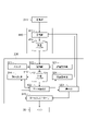
- control system 10 includes a control server 100, a time server 101, a local device 300, a communication device 200, and a communication device 400.
- Control server 100 includes a controller 111 that controls machine 30 .
- Local device 300 includes a local controller 315 that operates machine 30 .
- the communication device 200 and the communication device 400 perform communication between the control server 100 and the local device 300.
- the communication device 200 and the communication device 400 may be configured to perform network communication.
- Network communication means communication through a network of communication lines.
- the arrival time of the data set from the communication device 200 to the communication device 400 changes depending on which path is taken in the network communication line. This can be one of the causes of the exchange of the order of transmission and the order of reception described above.
- the communication device 200 and the communication device 400 may be configured to perform wireless communication.
- wireless communication a different communication delay may occur for each data set due to packet loss or the like. This can be one of the causes of the above-mentioned switching of the order of transmission and the order of reception.
- the communication device 200 and the communication device 400 may be configured to perform wireless network communication including wireless communication on at least part of the mesh communication line.
- the communication device 200 and the communication device 400 may be configured to perform wired communication.
- the communication device 200 and the communication device 400 may be configured to perform mobile communication.
- the communication device 200 may be a base station for mobile communication
- the communication device 400 may be a mobile station for mobile communication.
- the communication device 200 and the communication device 400 may be configured to perform communication (5G communication) by the fifth generation mobile communication system.
- the communication device 200 is connected to the control server 100 by wire.
- the communication device 200 transmits a plurality of command data sets acquired from the controller 111 to the corresponding communication device 400 .
- the communication device 400 is connected to the local device 300 by wire.
- the local device 300 acquires multiple command data sets that the communication device 400 receives from the communication device 200 .
- the communication device 200 and the communication device 400 constitute a part of the communication system 1. Furthermore, the control server 100 and the local device 300 also form part of the communication system 1 .
- the control server 100 is configured to add the order information to each of a plurality of command data sets that the communication device 200 acquires from the controller 111 .
- the local device 300 arranges the plurality of command data sets acquired from the communication device 400 in the waiting buffer in the order based on the order information, and sequentially arranges the plurality of command data sets stored in the waiting buffer in the arranged order. and configured to read.
- the local controller 315 operates the machine 30 based on the command data sets sequentially read by the local device 300 .
- the time server 101 is wired to the control server 100 and generates global time. As will be described later, the global time is used to match at least the time inside the control server 100 and the time inside the local device 300 .
- the time server 101 may be incorporated in the control server 100 or may be incorporated in the communication device 200 .
- control system 10 When the control system 10 includes a plurality of machines 30, the control system 10 may include a plurality of local devices 300 respectively corresponding to the plurality of machines 30 and a plurality of communication devices 400 respectively corresponding to the plurality of machines 30. good. Also, the control server 100 may have a plurality of controllers 111 respectively corresponding to the plurality of machines 30 .
- Each of the multiple local devices 300 includes a local controller 315 that operates the corresponding machine 30 .
- Each of the multiple local devices 300 is provided in the corresponding machine 30 .
- the local device 300 corresponding to the machine 30A is provided on the automatic guided vehicle 31 of the machine 30A
- the local device 300 corresponding to the machine 30B is provided on the automatic guided vehicle 33 of the machine 30B.
- the communication device 200 transmits a plurality of command data sets acquired from each of the plurality of controllers 111 to the corresponding communication device 400 .
- Each of the plurality of communication devices 400 causes the corresponding local device 300 to acquire the plurality of command data sets received from the communication device 200 .
- Each of the plurality of communication devices 400 is provided in the corresponding machine 30.
- the communication device 400 corresponding to the machine 30A is provided on the automatic guided vehicle 31 of the machine 30A
- the communication device 400 corresponding to the machine 30B is provided on the automatic guided vehicle 33 of the machine 30B.
- FIG. 3 is a block diagram illustrating functional configurations of the control server 100 and the communication device 200. As shown in FIG.
- the control server 100 has the plurality of controllers 111, the clock 112, and the information adding section 113 as functional components (hereinafter referred to as "functional blocks").
- Each of the multiple controllers 111 sequentially generates multiple command data sets for controlling the corresponding machine 30 .
- Each of the plurality of controllers 111 may repeat generation of command data sets for controlling the corresponding machine 30 in a constant control cycle. For example, each of the plurality of controllers 111 performs a control process including generating a command data set each time a periodic control clock signal is generated.
- a command data set is, for example, a data set representing an operation command for the machine 30 .
- a command data set may be a data set representing a target operation of machine 30 .
- the target motion includes a target position, target velocity, or the like of the machine 30 .
- the clock 112 repeatedly generates time at a constant cycle.
- server time the time generated by the clock 112 will be referred to as "server time”.
- Clock 112 may be configured to generate a server time that is synchronized with the global time.
- the clock 112 receives the global time from the time server 101 through communication that guarantees time synchronization, such as TSN (Time Sensitive Networking) communication via a wired communication network, and generates server time in synchronization with the received global time. do.
- the clock 112 synchronizes the server time with the global time, and then repeatedly updates the server time by counting clock pulses for a fixed cycle.
- the clock 112 may repeatedly synchronize the server time with the global time at predetermined time intervals.
- the information addition unit 113 adds the order information to each of the plurality of command data sets. For example, the information addition unit 113 adds order information and sends it to the communication device 200 each time the controller 111 generates a command data set. For example, the information addition unit 113 stores the command data set to which the order information is added in the transmission buffer 212 of the communication device 200 .
- the order information is information for determining the order of multiple command data sets.
- the order information has a value and determines the position (order) of each command data set in the above order based on comparison with other order information values.
- the information addition unit 113 adds order information having a larger value toward each of the plurality of command data sets so that the plurality of command data sets are arranged in a predetermined order.
- the information addition unit 113 may add order information including a count value from the top in the order of arrangement to each of the plurality of command data sets.
- the information addition unit 113 may add order information whose value decreases toward the end of the arrangement order to each of the plurality of command data sets. For example, the information adding unit 113 may add order information including a count value from the tail in the order of arrangement to each of the plurality of command data sets.
- the information addition unit 113 may add order information to each of the plurality of command data sets so that the order of the plurality of command data sets is the order of generation by the controller 111 .
- the information adding unit 113 adds to each of the plurality of command data sets order information whose value increases as it is generated later by the controller 111 .
- the information addition unit 113 adds order information including the server time at the time of generation to each of the plurality of command data sets.
- the server time at the time of generation will be referred to as "generation time”.
- the information adding unit 113 may add the order information including the server time immediately before adding the order information to each of the plurality of command data sets.
- the server time immediately before adding the order information will be referred to as "addition time”.
- the information addition unit 113 may add a count value that is counted up each time the controller 111 generates a command data set as order information to the command data set.
- the information addition unit 113 may add order information including timing information that determines the timing of reading the command data set by the local device 300 to each of the plurality of command data sets.
- the timing information may be information that directly specifies the read timing of the command data set by the local device 300 .
- the information addition unit 113 adds a predetermined delay time to the generation time or the addition time to calculate the readout time representing the readout timing, and adds the order information including the calculated readout time to each of the plurality of command data sets. .
- the timing information may be information that indirectly specifies the timing at which the local device 300 should read the command data set.
- the timing information may be information representing a reference timing before the transmission timing of the command data set by the communication device 200 (transmitting unit 211 described later). If the delay time from the reference timing to the readout timing is constant, the readout timing is indirectly determined by the generation time or the addition time. Examples of the information representing the reference timing include the time of generation or the time of addition.
- the control server 100 may have a plurality of information adding units 113 corresponding to the plurality of controllers 111 respectively.
- Each of the plurality of information addition units 113 adds the identification information and order information of the controller 111 and sends it to the communication device 200 every time the corresponding controller 111 generates a command data set. Based on the identification information of the controller 111 , it is possible to transmit the command data set generated by the controller 111 to the communication device 400 corresponding to the controller 111 .
- the communication device 200 has a transmission section 211 and a transmission buffer 212 as functional blocks.
- the transmission buffer 212 is a storage unit for temporarily storing a plurality of command data sets sent from the information addition unit 113 with order information added.
- the transmission unit 211 sequentially reads a plurality of command data sets to which order information is added from the transmission buffer 212 .
- the transmission unit 211 may read out a plurality of command data sets from the transmission buffer 212 using a FIFO (First In First Out) method. For example, the transmission unit 211 sequentially reads the plurality of command data sets stored in the transmission buffer 212 from the transmission buffer 212 in the order in which they were stored.
- FIFO First In First Out
- read includes excluding the data set read from the read destination such as the transmission buffer 212 from the next read target.
- An example of excluding the read data set from the next read target is to delete the read data set from the read destination. Instead of deleting the read data set from the next read target, a read flag is added to the read data set, and the read flag flagged data set is excluded from the next read target. good. The same applies to the case where data sets are read from other read destinations of the transmission buffer 212 below.
- the transmission unit 211 transmits the command data set read from the transmission buffer 212 to the communication device 400 .
- the transmission unit 211 may transmit the command data set through network communication, may transmit the command data set through wireless communication, or may transmit the command data set through mobile communication.
- the transmission unit 211 sends command data to the communication device 400 corresponding to the controller 111 based on the identification information of the controller 111 added to the command data set read from the transmission buffer 212 . Submit a set. Thereby, a plurality of command data sets generated by the corresponding controller 111 are sequentially transmitted to each of the plurality of communication devices 400 .
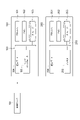
- FIG. 4 is a block diagram illustrating functional configurations of the local device 300 and the communication device 400.
- the communication device 400 has a receiving section 411 and a receiving buffer 412 as functional blocks.
- the receiver 411 sequentially receives a plurality of command data sets from the transmitter 211 .
- the receiving unit 411 may receive the command data set from the transmitting unit 211 through network communication, may receive the command data set from the transmitting unit 211 through wireless communication, or may receive the command data set from the transmitting unit 211 through mobile communication. may be received.
- the receiving unit 411 stores the plurality of command data sets in the receiving buffer 412 in the order in which they were received.
- the order in which the receiving unit 411 receives the multiple command data sets may differ from the order in which the transmitting unit 211 transmits the multiple command data sets.
- the local device 300 has a clock 311, an arrangement section 312, a standby buffer 313, a reading section 314, and a local controller 315 as functional blocks.
- a clock 311 repeatedly generates time at a constant cycle.
- the time generated by the clock 311 will be referred to as "local time”.
- the clock 311 may be configured to generate a local time synchronized with the global time.
- the clock 311 receives the server time from the control server 100 through communication such as TSN communication that guarantees time synchronization, and generates the local time in synchronization with the received server time.
- the clock 311 synchronizes the local time with the server time and then repeatedly updates the local time by counting clock pulses for a fixed cycle.
- the clock 311 may repeatedly synchronize the local time with the server time at predetermined time intervals.
- the standby buffer 313 is a storage unit for temporarily storing a plurality of command data sets in order based on order information.
- the arranging unit 312 arranges the plurality of command data sets received by the receiving unit 411 in the waiting buffer 313 in the order based on the order information. For example, the arrangement unit 312 reads out a plurality of command data sets from the reception buffer 412 using the FIFO method. For example, the arrangement unit 312 reads the plurality of command data sets stored in the reception buffer 412 from the reception buffer 412 in the order in which they were stored.
- the arrangement unit 312 arranges the plurality of command data sets read from the reception buffer 412 in the standby buffer 313 in the order based on the order information. For example, the arranging unit 312 arranges the data in the standby buffer 313 in the above-described predetermined order based on the order information. For example, when order information whose value increases as it is arranged later is added to each of the plurality of command data sets, the arranging unit 312 waits for the plurality of command data sets so that they are arranged in ascending order of the value of the order information. Arrange in buffer 313 . When order information whose value becomes smaller as it goes later in the order is added to each of the plurality of command data sets, the arranging unit 312 arranges the plurality of command data sets in order of increasing value of the order information. be arranged in
- the arranging unit 312 arranges the plurality of command data sets in the standby buffer 313 in the order of read timing based on the timing information. You may let
- the arranging unit 312 arranges the plurality of command data sets in the standby buffer 313 so that they are arranged in the order of the read time. good too.
- the arranging unit 312 may arrange the plurality of command data sets in the standby buffer 313 so that they are arranged in the order of the generation time.
- the arranging unit 312 may arrange the plurality of command data sets in the standby buffer 313 so that they are arranged in the order of the added time. .
- FIG. 5 is a schematic diagram illustrating the storage contents of the reception buffer 412 and the storage contents of the standby buffer 313.
- FIG. The numerical value shown in parentheses of each command data set represents the generation time.
- transmission of a plurality of command data sets by the transmission unit 211 is performed in order of generation time.
- the order of transmission of the plurality of command data sets and the order of reception of the plurality of command data sets may change, the order of the plurality of command data sets in the reception buffer 412 is not necessarily the order of generation time.
- a plurality of command data sets that are not arranged in order of generation time in the reception buffer 412 are rearranged in order of generation time in the waiting buffer 313 by the arranging section 312 .
- the reading unit 314 sequentially reads the plurality of command data sets stored in the standby buffer 313 in the order in which they are arranged.
- the reading unit 314 may repeat reading the command data set from the standby buffer 313 in a constant reading cycle. For example, the reading unit 314 reads the head data set located at the head of the arrangement in the standby buffer 313 among the plurality of command data sets each time a periodic read clock signal is generated.
- the reading unit 314 may read each of the plurality of command data sets at the reading timing specified by the timing information. For example, the reading unit 314 may read the leading data set when the reading time specified by the timing information of the leading data set is included in the execution period of the reading cycle.
- the leading data set whose read time specified by the timing information is included in the execution period of the read cycle is referred to as "read target data set”.
- cycle length of the read cycle and the cycle length of the control cycle are the same, there will be one data set to be read in each read cycle unless the instruction data set is missing. Reading of the command data set from 313 will be repeated in the read cycle.
- the reading unit 314 may read each of the plurality of command data sets at a reading timing after a predetermined delay time has elapsed from the reference timing.
- the arranging unit 312 may convert the reference timing included in the timing information into the read timing when storing each of the plurality of command data sets in the standby buffer 313 .
- the arrangement unit 312 may calculate the readout time by adding the delay time to the generation time or the addition time of the timing information, and include the calculated readout time in the timing information.
- the reading unit 314 reads the head data set when the reading time included in the order information by the arranging unit 312 is included in the execution period of the reading cycle.
- the arrangement unit 312 may convert the readout time specified by the timing information into the number of readout cycles from the time of storage in the standby buffer 313 (the time of storing the command data set in the standby buffer 313) to the readout time. For example, the arranging unit 312 may calculate the number of waiting cycles by dividing the time from the time of storing in the waiting buffer 313 to the time of reading by the reading cycle, and include the calculated number of waiting cycles in the timing information.
- the readout unit 314 repeatedly counts down the number of standby cycles of each of the plurality of command data sets arranged in the standby buffer 313 in read cycles, and reads the top data set whose number of standby cycles is zero from the standby buffer 313 .
- the number of waiting cycles being zero means that the read time is included in the execution period of the read cycle. Therefore, the head data set with the number of waiting cycles of zero is the read target data set.
- the local controller 315 operates the corresponding machine 30 based on the plurality of command data sets read by the reading unit 314 . For example, the local controller 315 causes the machine 30 to perform an action corresponding to the target action represented by the command data set each time the reading unit 314 reads the command data set. As a result, the control of the machine 30 is repeated in the local control cycle having the same cycle length as the read stop cycle. If the target motion includes a target position, local controller 315 repeats the local control cycle to cause machine 30 to follow the target position. If the target motion repeats the target speed, the local controller 315 causes the operating speed of the machine 30 to follow the target speed in repeated local control cycles.
- the local device 300 may further have a delay setting section 321 .
- the delay setting unit 321 sets the delay time for converting the reference timing into the read timing based on the input to the user interface.
- the local device 300 may further include a data confirmation section 322, a stop section 323, and a retransmission request section 324. Based on the arrangement of the plurality of command data sets in the standby buffer 313 and the timing information, the data confirmation unit 322 detects missing command data sets to be read in the read cycle.
- the data checking unit 322 detects the missing command data set to be read before the leading data set. For example, if the read time specified by the timing information of the leading data set is not included in the execution period of the reading cycle for reading the leading data set, the data checking unit 322 detects the lack of command data sets to be read before the leading data set. to detect
- a read cycle for reading the leading data set is hereinafter referred to as a "leading read cycle”.
- the lack of the command data set to be read before the leading data set is called “missing data set to be read”.
- the cycle length of the read cycle and the cycle length of the control cycle match, there is one data set to be read for each read cycle as long as no command data set is missing. Therefore, each read cycle becomes a "head read cycle”.
- the data confirmation unit 322 may detect lack of the read target data set when the number of waiting cycles of the leading data set is not zero.
- the data confirmation unit 322 may confirm whether or not the timing information of the leading data set corresponds to the leading read cycle after the leading reading cycle is started or before the leading reading cycle is started. .
- the reading unit 314 may wait to read the leading data set until the next reading cycle after the leading reading cycle.
- Missing command data set the lack of a command data set that should be placed between two command data sets.
- the stopping unit 323 stops the driving unit (for example, the actuators 71, 72, 73, 74, 75 of the machine 30) when the number of read cycles in which the lack of the command data set is continuously detected reaches a predetermined number of times of driving stop. , 76, the automatic guided vehicle 31, the automatic guided vehicle 33, etc.) are stopped.
- the stopping unit 323 stops communication between the transmitting unit 211 and the receiving unit 411 when the number of read cycles in which the lack of the command data set is continuously detected reaches a predetermined number of communication stops that is greater than the number of drive stops. may be stopped.
- the stopping unit 323 may stop the driving unit when the number of leading read cycles in which the missing data set to be read is continuously detected equals the number of drive stops.
- the stopping unit 323 may stop communication between the transmitting unit 211 and the receiving unit 411 when the number of lead read cycles in which the lack of the read target data set is continuously detected becomes the communication stop count.
- the stopping unit 323 may stop the driving unit when missing command data sets corresponding to the number of drive stop times are detected between the two command data sets.
- the stopping unit 323 may stop the communication between the transmitting unit 211 and the receiving unit 411 when missing command data sets corresponding to the number of communication stops are detected between the two command data sets.
- the resend request section 324 requests the transmission section 211 to resend the command data set in which the missing is detected. For example, when the data confirmation unit 322 detects the missing command data set, the retransmission request unit 324 may request the transmission unit 211 to retransmit the command data set in which the missing command data set is detected. The retransmission request unit 324 may request the transmitting unit 211 to retransmit the read target data set when missing of the read target data set is detected.
- the retransmission request unit 324 may cause the reception unit 411 to request the transmission unit 211 to retransmit the command data set.
- Transmitting section 211 may be configured to hold the transmitted command data set in preparation for a retransmission request from retransmission requesting section 324 .
- the arranging unit 312 may cause the receiving unit 411 to transmit an acknowledgment signal of the command data set to the transmitting unit 211 when the command data set is stored in the standby buffer 313 .
- the transmitter 211 may hold the command data set until it receives the acknowledge signal.
- the local controller 315 may be configured to sequentially obtain, from the machine 30, multiple feedback data sets including operational results based on multiple command data sets. Local controller 315 may repeatedly obtain feedback data sets in the local control cycle. For example, local controller 315 may obtain a feedback data set each time it operates machine 30 based on a command data set in the local control cycle.
- the controller 111 may be configured to generate the command data set based on the feedback data set obtained by the local controller 315 .
- the controller 111 may generate a command data set representing a target output (eg, a target torque or a target current) for causing the operation of the machine 30 represented by the feedback data set to follow the target operation.
- the controller 111 performs a proportional operation, a proportional/integral operation, or a proportional/integral/differential operation on the deviation between the target operation and the operation of the machine 30 represented by the feedback data set to generate the command data set representing the target output.
- the communication system 1 adds second order information to each of the plurality of feedback data sets acquired by the local controller 315, and sequentially transmits the plurality of feedback data sets to which the second order information is added. and Sequentially receiving the transmitted multiple feedback data sets, arranging the received multiple feedback data sets in the second waiting buffer in the order based on the second order information, and and sequentially reading the plurality of feedback data sets in an arranged order.
- local controller 315 is the supplying application and controller 111 is the consuming application.
- the local device 300 may further have a second information addition section 331 .
- the second information adding section 331 adds second order information to each of the plurality of feedback data sets acquired by the local controller 315 .
- the second information addition unit 331 adds the second order information and sends it to the communication device 400 .
- the second information addition unit 331 stores the feedback data set with the second order information added in the second transmission buffer 422 of the communication device 400 .
- the second order information is information for determining the order in which multiple feedback data sets are arranged.
- the second order information has a value and determines the position (order) of each feedback data set in the above order based on comparison with other second order information values.
- the second information adding unit 331 adds second order information having a larger value toward each of the plurality of feedback data sets so that the plurality of feedback data sets are arranged in a predetermined order.
- the second information adding section 331 may add second order information including a count value from the top in the order of arrangement to each of the plurality of feedback data sets.
- the second information adding section 331 may add second order information whose value becomes smaller as it goes later in the order of arrangement to each of the plurality of feedback data sets.
- the second information adding section 331 may add second order information including a count value from the tail in the order of arrangement to each of the plurality of feedback data sets.
- the second information addition unit 331 may add second order information to each of the plurality of feedback data sets so that the order of the plurality of feedback data sets is the order of acquisition by the local controller 315 .
- the second information adding unit 331 adds the second order information whose value increases as it gets later in the order of acquisition by the local controller 315 to each of the plurality of feedback data sets.
- the second information addition unit 331 adds order information including the local time at the time of acquisition to each of the plurality of feedback data sets.
- acquisition time the local time at the time of acquisition
- the second information adding section 331 may add the second order information including the local time immediately before adding the second order information to each of the plurality of feedback data sets.
- second addition time the local time immediately before adding the second order information
- the second information addition unit 331 may add a count value that is incremented every time the local controller 315 acquires the feedback data set as the second order information to the feedback data set.
- the second information addition unit 331 may add second order information including second timing information that determines the read timing of the feedback data set by the control server 100 to each of the plurality of feedback data sets.
- the second timing information may be time information that directly specifies the read timing of the feedback data set by the control server 100 (hereinafter referred to as “second read timing”).
- second read timing time information that directly specifies the read timing of the feedback data set by the control server 100
- the second information addition unit 331 adds a predetermined second delay time to the acquisition time or the second addition time to calculate a second readout time representing the second readout timing, and calculates a second readout time including the calculated second readout time. 2. Order information is added to each of the multiple feedback data sets.
- the second timing information may be time information that indirectly specifies the timing at which the control server 100 should read the feedback data set.
- the second timing information may be information representing a second reference timing before the transmission timing of the feedback data set by the communication device 400 (second transmission section 421 described later). If the second delay time from the second reference timing to the second readout timing is constant, the second readout timing is indirectly determined by the acquisition time or the second additional time. Examples of information representing the second reference timing include the acquisition time or the second addition time.
- the second information addition unit 331 adds identification information and second order information of the corresponding machines 30 and sends them to the communication device 400 . Based on the identification information of the machine 30, the feedback data set can be obtained by the controller 111 corresponding to the machine 30.
- the communication device 400 may further include a second transmission section 421 and a second transmission buffer 422.
- the second transmission buffer 422 is a storage unit for temporarily storing a plurality of feedback data sets added with the second order information and sent from the second information adding unit 331 .
- the second transmission unit 421 sequentially reads the plurality of feedback data sets to which the second order information is added from the second transmission buffer 422 .
- the second transmission unit 421 may read multiple feedback data sets from the second transmission buffer 422 in the FIFO method. For example, the second transmission unit 421 sequentially reads the plurality of feedback data sets stored in the second transmission buffer 422 from the second transmission buffer 422 in the order in which they were stored.
- the second transmission unit 421 transmits the feedback data set read from the second transmission buffer 422 to the communication device 200 .
- the second transmitter 421 may transmit the feedback data set through network communication, may transmit the feedback data set through wireless communication, or may transmit the feedback data set through mobile communication.
- the communication device 200 further includes a second receiving section 221 and a second receiving buffer 222.
- the second receiver 221 sequentially receives a plurality of feedback data sets from the second transmitter 421 .
- the second receiving unit 221 may receive the feedback data set from the second transmitting unit 421 through network communication, may receive the feedback data set from the second transmitting unit 421 through wireless communication, or may receive the feedback data set through mobile communication. 2 may receive a feedback data set from the transmitter 421 .
- the second receiving unit 221 stores the plurality of feedback data sets in the second receiving buffer 222 in the order in which they were received.
- the order in which the second receiver 221 receives the multiple feedback data sets may differ from the order in which the second transmitter 421 transmits the multiple feedback data sets.
- the second receiving unit 221 may add identification information of the local controller 315 that acquired the feedback data set to the feedback data set and store the feedback data set in the second reception buffer 222. . This enables each of the plurality of controllers 111 to acquire the plurality of feedback data sets acquired by the corresponding local controller 315 .
- the control server 100 further has a second arrangement section 121 , a second standby buffer 122 and a second reading section 123 .
- the second standby buffer 122 is a storage unit for temporarily storing a plurality of feedback data sets in order based on the second order information.
- the second arranging section 121 arranges the plurality of feedback data sets received by the second receiving section 221 in the second standby buffer 122 in the order based on the second order information. For example, the second arrangement unit 121 reads multiple feedback data sets from the second reception buffer 222 in a FIFO manner. For example, the second arrangement unit 121 reads the plurality of feedback data sets stored in the second reception buffer 222 from the second reception buffer 222 in the order in which they were stored.
- the second arrangement unit 121 arranges the plurality of feedback data sets read from the second reception buffer 222 in the second standby buffer 122 in the order based on the second order information. For example, the second arranging unit 121 arranges in the second waiting buffer 122 in the above-described predetermined order based on the second order information. For example, when the second order information whose value increases as it is arranged later is added to each of the plurality of feedback data sets, the second arrangement unit 121 arranges the plurality of feedback data sets so that the value of the second order information is arranged in ascending order. of feedback data sets are arranged in the second waiting buffer 122 .
- the second arrangement unit 121 arranges the plurality of feedback data so that the value of the second order information is arranged in descending order. Arrange the data set in the second waiting buffer 122 .
- the second arrangement unit 121 sorts the plurality of feedback data sets into the second order information based on the second timing information. They may be arranged in the second standby buffer 122 in order of read timing.
- the second arrangement unit 121 arranges the plurality of feedback data sets in order of the second readout time. may be arranged in the second waiting buffer 122 .
- the second arranging unit 121 arranges the plurality of feedback data sets in the second standby buffer 122 so as to be arranged in the order of acquisition time. can be arranged in
- the second arrangement unit 121 arranges the plurality of feedback data sets in the order of the second addition time. 2 waiting buffer 122 .
- the second reading unit 123 sequentially reads the plurality of feedback data sets stored in the second standby buffer 122 in the order in which they are arranged.
- the second reading unit 123 may repeat reading the command data set from the second standby buffer 122 in a constant second reading cycle. For example, the second reading unit 123 reads the top data set located at the top of the arrangement in the second standby buffer 122 among the plurality of feedback data sets each time the periodic second read clock signal is generated.
- the second reading unit 123 removes the read head data set from the array in the second standby buffer 122 .
- the second reading unit 123 may read each of the plurality of feedback data sets at the second reading timing specified by the second timing information. For example, the second reading unit 123 may read the leading data set when the second reading time specified by the second timing information of the feedback data set is included in the execution period of the second reading cycle.
- the head data set whose second read time specified by the second timing information is included in the execution period of the second read cycle is referred to as "read target data set”.
- the second reading unit 123 may read each of the plurality of feedback data sets at a second reading timing after a predetermined second delay time has elapsed from the second reference timing.
- the second arrangement unit 121 may convert the second reference timing included in the second timing information into the second read timing when storing each of the plurality of feedback data sets in the second standby buffer 122.
- the second arrangement unit 121 calculates the second readout time by adding the second delay time to the acquisition time or the second addition time of the second timing information, and includes the calculated second readout time in the second timing information.
- the second reading unit 123 reads the leading data set when the second reading time included in the second order information by the second arranging unit 121 is included in the execution period of the second reading cycle.
- the second arrangement unit 121 arranges the second read time specified by the second timing information from the time of storage in the second standby buffer 122 (the time of storing the feedback data set in the second standby buffer 122) to the second read time. may be converted into the number of second read cycles. For example, the second array unit 121 calculates the second standby cycle number by dividing the time from the storage time in the second standby buffer 122 to the second readout time by the second readout cycle, and calculates the calculated second standby cycle number. may be included in the second timing information.
- the second reading unit 123 repeatedly counts down the second waiting cycle number of each of the plurality of feedback data sets arranged in the second waiting buffer 122 in the second reading cycle, and reads the leading data whose second waiting cycle number is zero. Read the set from the second wait buffer 122 .
- the fact that the second wait cycle number is zero means that the second read time is included in the execution period of the second read cycle. Therefore, the head data set whose second wait cycle number is zero is the read target data set.
- the controller 111 generates command data sets based on the feedback data sets read by the second reading unit 123 .
- the control server 100 may have multiple second array units 121 , multiple second standby buffers 122 , and multiple second read units 123 .
- the plurality of second array units 121 correspond to the plurality of controllers 111
- the plurality of second standby buffers 122 respectively correspond to the plurality of second array units 121
- the plurality of second reading units 123 correspond to the plurality of second array units 121, respectively. 2 waiting buffers 122, respectively.
- Each of the plurality of second arrangement units 121 reads the feedback data from the corresponding local controller 315 from the second reception buffer 222 based on the identification information of the local controller 315 added to the feedback data set, Send to waiting buffer 122 .
- multiple feedback data sets acquired by the corresponding local controller 315 are stored in each of the multiple second standby buffers 122 .
- the control server 100 may further have a second delay setting unit 131.
- a second delay setting unit 131 sets a second delay time for converting the second reference timing to the second read timing based on an input to the user interface.
- the control server 100 may further include a second data confirmation section 132, a second stop section 133, and a second retransmission request section .
- the control server 100 may further have a plurality of sets of second data confirmation section 132, second stop section 133, and second retransmission request section 134 corresponding to the plurality of controllers 111 respectively. good.
- the second data confirmation unit 132 detects missing feedback data sets to be read in the second read cycle based on the arrangement of the plurality of feedback data sets in the second standby buffer 122 and the second timing information.
- the second data checking unit 132 detects the lack of the feedback data set to be read before the leading data set. . For example, if the second read time specified by the second timing information of the leading data set is not included in the execution period of the second reading cycle for reading the leading data set, the second data checking unit 132 determines whether the second data set is read before the leading data set. Detect missing feedback data set to be read out.
- a read cycle for reading the leading data set is hereinafter referred to as a "leading read cycle”.
- the missing of the feedback data set to be read before the leading data set is referred to as "missing of the read target data set”.
- the cycle length of the second read cycle and the cycle length of the local control cycle match, there is one data set to be read for each second read cycle unless a feedback data set is missing. do. Therefore, each second read cycle becomes a "head read cycle".
- the second data confirmation unit 132 may detect lack of the read target data set when the second waiting cycle number of the leading data set is not zero.
- the second data confirmation unit 132 may confirm whether or not the second timing information of the head data set corresponds to the head read cycle after the head read cycle starts, or may confirm before the head read cycle starts. good too.
- the second reading unit 123 may wait until the second reading cycle following the leading reading cycle before reading the leading data set when missing of the reading target data set is detected.
- the second data confirmation unit 132 determines that the difference between the two feedback data sets adjacent to each other in the arrangement of the second standby buffer 122 is equal to or greater than twice the second read cycle. Missing feedback data sets that should be placed between feedback data sets may be detected. Hereinafter, the lack of a feedback data set that should be placed between two feedback data sets is referred to as "missing feedback data set”.
- the second stopping unit 133 stops the driving unit (for example, the actuators 71 and 72 of the machine 30) when the number of second read cycles in which the lack of the feedback data set is continuously detected reaches a predetermined number of second driving stops. , 73, 74, 75, 76, the automatic guided vehicle 31, and the automatic guided vehicle 33, etc.).
- the driving unit for example, the actuators 71 and 72 of the machine 30
- 73, 74, 75, 76 the automatic guided vehicle 31, and the automatic guided vehicle 33, etc.
- the second stopping unit 133 may cause the controller 111 to output a command to stop the driving unit when the number of leading read cycles in which the lack of the data set to be read is detected reaches the second drive stop count.
- the second stopping unit 133 stops the communication between the second receiving unit 221 and the second transmitting unit 421 when the number of leading read cycles in which the lack of the data set to be read is continuously detected reaches the second communication stop count. Communication may be stopped.
- the second stopping unit 133 may cause the controller 111 to output a command to stop the driving unit when a missing feedback data set corresponding to the second number of drive stops is detected between the two feedback data sets.
- the second stopping unit 133 suspends communication between the second receiving unit 221 and the second transmitting unit 421 when a missing feedback data set corresponding to the second communication stop count is detected between the two feedback data sets. You can stop it.
- the second retransmission request unit 134 requests the second transmission unit 421 to retransmit the missing feedback data set. For example, when the second data confirmation unit 132 detects the missing feedback data set, the second retransmission request unit 134 requests the second transmission unit 421 to retransmit the feedback data set in which the missing feedback data set is detected. good. The second retransmission request unit 134 may request the second transmission unit 421 to retransmit the read target data set when missing of the read target data set is detected.
- the second retransmission request unit 134 may cause the second reception unit 221 to request the second transmission unit 421 to retransmit the feedback data set.
- the second transmission section 421 may be configured to hold the transmitted feedback data set in preparation for the retransmission request of the second retransmission request section 134 .
- the second arrangement section 121 may cause the second receiving section 221 to transmit an acknowledgment signal of the feedback data set to the second transmitting section 421 .
- the second transmitter 421 may hold the feedback data set until it receives the acknowledge signal.
- FIG. 9 is a block diagram illustrating the hardware configuration of the control server 100 and the communication device 200. As shown in FIG. As shown in FIG. 9, the control server 100 has circuitry 190 . Circuit 190 has processor 191 , memory 192 , storage 193 , communication port 194 and user interface 195 .
- the storage 193 is a non-volatile storage medium. Specific examples of the storage 193 include a hard disk, flash memory, and the like. The storage 193 may be a portable storage medium such as an optical disc.
- the storage 193 stores a program for causing the control server 100 to control the machine 30 and add the order information to each of a plurality of command data sets to be sent to the communication device 200 . For example, the storage 193 stores a program for causing the control server 100 to configure each functional block described above.
- the memory 192 is a temporary storage medium such as random access memory, and temporarily stores programs loaded from the storage 193 .
- the processor 191 is composed of one or more arithmetic elements, and executes a program loaded in the memory 192 to cause the control server 100 to configure each of the above functional blocks.
- the communication port 194 communicates with the time server 101 and the communication device 200 in response to requests from the processor 191 .
- the user interface 195 is a device for performing input by the user and presenting information to the user, and includes, for example, an input device and a display device.
- input devices include keyboards, mice, keypads, and the like.
- display devices include liquid crystal monitors and organic EL (Electro-Luminescence) monitors.
- the input device may be integrated with the display device as a so-called touch panel.
- the communication device 200 has a circuit 290.
- Circuit 290 has processor 291 , memory 292 , storage 293 and communication port 294 .
- the storage 293 is a non-volatile storage medium. Specific examples of the storage 193 include a hard disk, flash memory, and the like. The storage 193 may be a portable storage medium such as an optical disc. The storage 293 stores programs for configuring the functional blocks described above in the communication device 200 .
- the memory 292 is a temporary storage medium such as random access memory, and temporarily stores programs loaded from the storage 293 .
- the processor 291 is composed of one or more arithmetic elements, and executes a program loaded in the memory 292 to cause the communication device 200 to configure each of the functional blocks described above.
- Communication port 294 communicates with communication port 194 in response to requests from processor 291 .
- Antenna 295 transmits and receives a signal for wireless communication according to a request from processor 291 .
- FIG. 10 is a block diagram illustrating the hardware configuration of the local device 300 and the communication device 400.
- local device 300 has circuitry 390 .
- Circuitry 390 includes processor 391 , memory 392 , storage 393 , communication port 394 and drive circuitry 395 .
- the storage 393 is a non-volatile storage medium. Specific examples of the storage 393 include a hard disk, flash memory, and the like.
- the storage 393 may be a portable storage medium such as an optical disc.
- the storage 393 arranges the plurality of command data sets acquired from the communication device 400 in the waiting buffer in the order based on the order information, and sequentially reads out the plurality of command data sets stored in the waiting buffer in the arranged order. and operating the machine 30 based on the read command data set.
- the storage 393 stores a program for causing the local device 300 to configure each functional block described above.
- the memory 392 is a temporary storage medium such as random access memory, and temporarily stores programs loaded from the storage 393 .
- the processor 391 is composed of one or more arithmetic elements, and executes a program loaded in the memory 392 to configure the above functional blocks in the local device 300 .
- Communication port 394 communicates with communication device 400 in response to requests from processor 391 .
- the drive circuit 395 outputs drive power to the machine 30 and acquires feedback data sets from the machine 30 in response to requests from the processor 391 .
- the user interface 396 is a device for inputting by the user and presenting information to the user, and includes, for example, an input device and a display device.
- input devices include keyboards, mice, keypads, and the like.
- display devices include liquid crystal monitors and organic EL (Electro-Luminescence) monitors.
- the input device may be integrated with the display device as a so-called touch panel.
- the communication device 400 has a circuit 490.
- Circuit 490 has processor 491 , memory 492 , storage 493 and communication port 494 .
- the storage 493 is a non-volatile storage medium. Specific examples of the storage 493 include a hard disk, flash memory, and the like.
- the storage 193 may be a portable storage medium such as an optical disc.
- Storage 493 stores a program for configuring each functional block described above in communication device 400 .
- the memory 492 is a temporary storage medium such as random access memory, and temporarily stores programs loaded from the storage 493 .
- the processor 491 is composed of one or more arithmetic elements, and executes a program loaded in the memory 492 to make the communication device 400 configure each of the above functional blocks.
- Communication port 494 communicates with communication port 494 in response to requests from processor 491 .
- Antenna 495 transmits and receives a signal for wireless communication according to a request from processor 491 .
- the communication system 1 may comprise multiple hardware devices each including multiple controllers 111 .
- an information adding unit 113, a second arranging unit 121, a second standby buffer 122, a second reading unit 123, a second delay setting unit 131, and a second data checking unit, which constitute a part of the communication system 1 132 , the second stop unit 133 and the second retransmission request unit 134 may be incorporated in the communication device 200 .
- the adding unit 331 may be incorporated in the communication device 400 .
- the communication device 200 may be incorporated in the control server 100 and the communication device 400 may be incorporated in the local device 300 .
- This control procedure consists of sequentially generating a plurality of command data sets, adding order information to each of the plurality of command data sets, and sequentially transmitting the plurality of command data sets to which the order information is added. and sequentially receive the plurality of transmitted command data sets; arrange the received plurality of command data sets in the standby buffer 313 in the order based on the order information; and sequentially reading the command data sets in sequenced order.
- the above control procedure will be described below as a command data set generation and transmission procedure executed by the control server 100, a plurality of feedback data set arrangement procedures executed by the control server 100, a communication procedure executed by the communication device 200, and a local control procedure.
- a local control procedure executed by the device 300, a procedure for arranging a plurality of command data sets executed by the local device 300, and a communication procedure executed by the communication device 400 are illustrated separately.
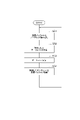
- FIG. 11 is a flow chart illustrating a procedure for generating and transmitting a command data set.
- the flowchart of FIG. 11 is executed while the plurality of feedback data sets are stored in the second standby buffer 122 in the order based on the second order information.
- the second order information of each of the plurality of feedback data sets includes second timing information converted into a second read cycle number from the time of storage in the second standby buffer 122 to the second read time.
- the control server 100 first executes steps S01 and S02.
- step S ⁇ b>01 the second reading unit 123 counts down the number of second reading cycles by one for each of the plurality of feedback data sets in the second standby buffer 122 .
- step S ⁇ b>02 the second reading unit 123 checks whether or not there is a data set to be read in the second standby buffer 122 . For example, the second reading unit 123 confirms whether or not the number of second read cycles of the leading data set in the second standby buffer 122 is zero.
- step S02 When it is determined in step S02 that there is a data set to be read, the control server 100 executes steps S03, S04, S05, and S06.
- step S ⁇ b>03 the second reading unit 123 reads the head data set (feedback data set) from the second standby buffer 122 .
- step S ⁇ b>04 the controller 111 generates a command data set based on the first data set read by the second standby buffer 122 .
- step S ⁇ b>05 the information addition unit 113 adds order information to the command data set generated by the controller 111 .
- step S ⁇ b>06 the information addition unit 113 stores the command data set with the order information added in the transmission buffer 212 .
- step S07 the second data confirmation unit 132 confirms whether or not there is a missing feedback data set in the second standby buffer 122 . If it is determined in step S07 that the feedback data set is missing, the control server 100 executes step S08. In step S08, second retransmission requesting section 134 requests second transmitting section 421 to retransmit the feedback data set in which the missing is detected.
- step S09 the second reading unit 123 waits for the second reading cycle to elapse. After that, the control server 100 returns the process to step S01.
- step S12 the second stopping unit 133 confirms whether or not the number of leading read cycles in which the lack of the data set to be read is continuously detected is the second driving stop count.
- the number of leading read cycles in which the missing data set to be read is continuously detected will be referred to as the “continuous missing count”.
- step S12 If it is determined in step S12 that the number of times of continuous missing is the number of times of stopping the second drive, the control server 100 executes step S13.
- step S ⁇ b>13 the second stopping unit 133 causes the controller 111 to output a command to stop the operation of the machine 30 .
- step S14 the control server 100 executes step S14. If it is determined in step S12 that the number of consecutive dropouts is not the number of times of the second drive stop, the control server 100 executes step S14 without executing step S13.
- step S14 the second stopping unit 133 confirms whether or not the number of times of consecutive omissions is the second number of times of communication stopping. If it is determined in step S14 that the number of consecutive omissions is not the number of second communication stoppages, the control server 100 advances the process to step S09. Thereafter, after waiting for the read cycle to elapse, the process returns to step S01. Therefore, reading of the head data set is delayed until the next read cycle.
- step S14 when it is determined that the number of consecutive omissions is the number of second communication stoppages, the control server 100 executes step S15.
- step S ⁇ b>15 the second stopping section 133 stops communication between the second receiving section 221 and the second transmitting section 421 . This completes the command data set generation and transmission procedure.
- step S ⁇ b>21 the arrangement unit 312 waits for one or more instruction data sets to be stored in the reception buffer 412 .
- step S22 the arrangement unit 312 reads out the command data sets from the reception buffer 412 in the order in which they were stored.
- step S23 the arranging unit 312 converts the read timing information of the command data set into the number of read cycles from the storage time in the standby buffer 313 to the read time.
- step S24 the arranging unit 312 arranges the command data sets obtained by converting the timing information into the number of read cycles in the standby buffer 313 in the order of the read timings determined by the timing information (in descending order of the number of read cycles).
- step S25 the arranging unit 312 checks whether or not there are any unread command data sets left in the receiving buffer 412. If it is determined in step S25 that the command data set that has not been read remains in the reception buffer 412, the local device 300 returns the process to step S22. Thereafter, reading of the command data set and arrangement in the standby buffer 313 are repeated until reading of the command data set from the reception buffer 412 is completed. If it is determined in step S25 that no unread command data set remains in the reception buffer 412, the local device 300 returns the process to step S21. The local device 300 repeatedly executes the above processing.
- step S31 the transmission unit 211 reads out the command data sets from the transmission buffer 212 in the order in which they were stored.
- step S ⁇ b>32 the transmission unit 211 transmits the read instruction data set to the reception unit 411 .
- step S ⁇ b>33 the second receiver 221 receives the feedback data set transmitted from the second transmitter 421 .
- step S ⁇ b>34 the second receiver 221 stores the received feedback data set in the second transmission buffer 422 .
- FIG. 14 is a flow chart illustrating the local control procedure.
- the flowchart of FIG. 14 is executed while a plurality of command data sets are stored in the standby buffer 313 in the order based on the order information.
- the order information for each of the plurality of command data sets includes timing information converted into the number of read cycles from the time of storage in the standby buffer 313 to the time of readout.
- the local device 300 first executes steps S41 and S42.
- step S ⁇ b>41 the reading unit 314 counts down the number of read cycles by one for each of the plurality of command data sets in the standby buffer 313 .
- step S ⁇ b>42 the reading unit 314 checks whether or not there is a data set to be read in the standby buffer 313 . For example, the reading unit 314 confirms whether or not the number of read cycles of the leading data set in the standby buffer 313 is zero.
- step S42 If it is determined in step S42 that there is a data set to be read, the local device 300 executes steps S43 and S44.
- step S ⁇ b>43 the reading unit 314 reads the head data set (command data set) from the standby buffer 313 .
- step S44 the local controller 315 confirms whether or not the command data set read by the standby buffer 313 is a stop command.
- step S44 If it is determined in step S44 that the command data set is not a stop command, the local device 300 executes steps S45, S46, and S47.
- step S ⁇ b>45 the local controller 315 operates the machine 30 based on the command data set read by the reading unit 314 and obtains a feedback data set representing the operation result of the machine 30 .
- step S ⁇ b>46 the second information adding section 331 adds second order information to the feedback data set acquired by the local controller 315 .
- step S ⁇ b>47 the second information addition unit 331 stores the feedback data set with the second order information added in the second transmission buffer 422 .
- step S51 the local device 300 executes step S51.
- step S ⁇ b>51 the data confirmation unit 322 confirms whether or not there is a missing command data set in the standby buffer 313 . If it is determined in step S22 that the instruction data set is missing, the local device 300 executes step S52.
- step S52 the retransmission request unit 324 requests the transmission unit 211 to retransmit the instruction data set in which the omission is detected.
- step S53 the local device 300 executes step S53.
- step S51 the local device 300 executes step S51 without executing step S52.
- step S53 the second reading unit 123 waits for the reading cycle to elapse. After that, the control server 100 returns the process to step S41.
- step S42 When it is determined in step S42 that there is no data set to be read, the local device 300 executes steps S61 and S62.
- step S61 the data confirmation unit 322 detects missing of the read target data set and notifies the occurrence of the missing. For example, the data confirmation unit 322 notifies the occurrence of omission by displaying on the display device of the user interface 396 or the like.
- step S62 the stopping unit 323 confirms whether or not the number of leading read cycles in which the lack of the data set to be read is continuously detected is the drive stop count.
- the number of leading read cycles in which the missing data set to be read is continuously detected will be referred to as the “continuous missing count”.
- step S62 If it is determined in step S62 that the number of times of continuous missing is the number of times of stopping driving, the local device 300 executes step S63. Also when it determines with a command data set being a stop command in step S44, the local device 300 performs step S63. In step S ⁇ b>63 , the stopping unit 323 causes the local controller 315 to stop the operation of the machine 30 .
- step S64 when it determines with the frequency
- step S64 the stopping unit 323 confirms whether or not the number of consecutive missing times is equal to the number of communication stop times.
- step S64 when it determines with the frequency
- step S65 If it is determined in step S64 that the number of consecutive omissions is the number of communication stoppages, the local device 300 executes step S65. In step S ⁇ b>65 , the stopping unit 323 stops communication between the transmitting unit 211 and the receiving unit 411 . This completes the local control procedure.
- step S ⁇ b>71 the second arrangement unit 121 waits for one or more feedback data sets to be stored in the second reception buffer 222 .
- step S72 the second arrangement unit 121 reads out the feedback data sets from the second reception buffer 222 in the order in which they were stored.
- step S ⁇ b>73 the second arrangement unit 121 converts the timing information of the read feedback data set into a second read cycle number from the storage time in the second standby buffer 122 to the second read time.
- step S74 the second array unit 121 arranges the feedback data set obtained by converting the timing information into the second read cycle number in the order of the second read timings determined by the timing information (in descending order of the second read cycle number). Arrange them in the waiting buffer 122 .
- step S75 the second arrangement unit 121 confirms whether or not any unread feedback data set remains in the second reception buffer 222. If it is determined in step S75 that the feedback data set that has not been read remains in the second reception buffer 222, the control server 100 returns the process to step S72. After that, the reading of the feedback data set and the arrangement in the second standby buffer 122 are repeated until the reading of the feedback data set from the second reception buffer 222 is completed. If it is determined in step S75 that no unread feedback data set remains in the second reception buffer 222, the control server 100 returns the process to step S71. The control server 100 repeatedly executes the above processing.
- step S81 the second transmission unit 421 reads out the feedback data sets from the second transmission buffer 422 in the order in which they were stored.
- step S ⁇ b>82 the second transmitter 421 transmits the read feedback data set to the second receiver 221 .
- step S ⁇ b>83 the receiving section 411 receives the instruction data set transmitted from the transmitting section 211 .
- step S ⁇ b>84 the receiving unit 411 stores the received instruction data set in the receiving buffer 412 .
- the communication system 1 includes the information addition unit 113 that adds order information to each of a plurality of data sets, the transmission unit 211 that sequentially transmits the plurality of data sets to which the order information is added, A receiving unit 411 that sequentially receives a plurality of data sets from the transmitting unit 211; and a reading unit 314 that sequentially reads out the plurality of stored data sets in the order in which they are arranged.
- the order of sending multiple data sets and the order of receiving multiple data sets may change. For example, an earlier transmitted data set may be received later than a later transmitted data set. Even if the order of transmission and the order of reception are reversed, according to the communication system 1, a plurality of data sets can be sequentially read in the order based on the order information. Therefore, regardless of the order of reception, the order of use of a plurality of data sets can be controlled by the order information. Therefore, the communication system 1 is effective in using a plurality of data sets received through communication in proper order.
- the order information may include timing information that determines read timing, and the reading unit 314 may read each of the plurality of data sets at the read timing specified by the timing information. Read timing can be appropriately controlled based on the timing information.
- the arranging unit 312 may arrange the plurality of data sets in the standby buffer 313 in order of read timing based on the timing information included in the order information. Since both the arrangement by the arrangement unit 312 and the readout timing by the readout unit 314 are controlled by the timing information, the information added to the data set can be reduced.
- the timing information is information representing the reference timing before the transmission timing by the transmission unit 211, and the reading unit 314 may read each of the plurality of data sets at the reading timing after a predetermined delay time has elapsed from the reference timing. By adjusting the delay time, the read timing can be easily adjusted.
- a delay setting unit 321 that sets the delay time based on an input to the user interface may be further provided. In this case, the read timing can be easily changed according to the application of the communication system 1 .
- the reading unit 314 repeats reading data sets from the standby buffer 313 in a constant reading cycle, and the communication system 1 reads the data sets in the reading cycle based on the arrangement of the plurality of data sets in the standby buffer 313 and the timing information.
- a data confirmation unit 322 that detects missing data sets may be further provided. Missing data sets can be easily detected based on the relationship between the read cycle and the timing information.
- the plurality of data sets includes data sets used to control drives (e.g., actuators 71, 72, 73, 74, 75, 76 of machine 30, AGV 31, AGV 33, etc.), and the communication system 1 may further include a stopping unit 323 for stopping the driving unit when the number of read cycles in which missing data sets are continuously detected reaches a predetermined number of driving stops. Unexpected operation of the driving unit due to unstable communication can be avoided.
- the stopping unit 323 stops communication between the transmitting unit and the receiving unit when the number of read cycles in which the lack of data sets is continuously detected reaches a predetermined number of times of communication stop, which is greater than the number of times of stopping the drive. good too. In this case, it is possible to avoid excessive continuation of unstable communication while maintaining communication even after the driving unit is stopped.
- the data confirmation unit 322 detects the missing data set to be read before the head data set. may be detected. Missing data sets can be detected more easily.
- the reading unit 314 may wait to read the leading data set until the next reading cycle after the reading cycle in which the leading data set is to be read, when the lack of the data set to be read before the leading data set is detected. . Order information-based ordering can be used to easily handle missing data sets.
- a retransmission request unit 324 may be further provided that requests the transmission unit 211 to retransmit the data set when the data confirmation unit 322 detects that the data set is missing. Missing datasets can be suppressed.
- the transmission section 211 may hold the transmitted data set in preparation for the retransmission request of the retransmission request section 324 . Missing data sets can be further suppressed.
- the receiving unit 411 stores the plurality of data sets in the receiving buffer 412 in the order in which they were received, and the arranging unit 312 reads out the plurality of data sets stored in the receiving buffer 412 from the receiving buffer 412 in the order in which they were stored, and arranges the data sets in the order. They may be arranged in the waiting buffer 313 in order based on the information. It is possible to simplify the configuration of the reception buffer 412 on the premise that the order of arrangement is arranged by the arrangement unit 312 .
- the transmission unit 211 may transmit the data set through network communication, and the reception unit 411 may receive the data set from the transmission unit 211 through network communication. According to network communication, the order is likely to be changed. Therefore, it is more effective to control the order of use of a plurality of data sets by means of order information regardless of the order of reception.
- the transmitting unit 211 may transmit the data set by wireless communication, and the receiving unit 411 may receive the data set from the transmitting unit 211 by wireless communication. Therefore, it is more effective to control the order of use of a plurality of data sets by means of order information regardless of the order of reception.
- the transmitting unit 211 may transmit the dataset via mobile communication, and the receiving unit 411 may receive the dataset from the transmitting unit 211 via mobile communication. According to mobile communication, the order is likely to be changed. Therefore, it is more effective to control the order of use of a plurality of data sets by means of order information regardless of the order of reception.
- the control system 10 includes the communication system 1, a controller 111 that sequentially generates a plurality of command data sets, and a local controller 315 that operates the machine based on the plurality of command data sets.
- 111 adds order information to each of the plurality of command data sets generated
- the transmitting unit 211 sequentially transmits the plurality of command data sets to which the order information is added
- the receiving unit 411 transmits the plurality of command data sets.
- the arranging unit 312 arranges the plurality of command data sets received by the receiving unit 411 in the order based on the order information in the standby buffer 313, and the reading unit 314 receives the plurality of command data sets stored in the waiting buffer 313.
- the data sets are sequentially read out in the order in which they are arranged, and the local controller 315 operates the machine based on the plurality of command data sets read by the reading unit 314 .
- the communication system 1 can be effectively used for synchronous communication in machine control.
- the local controller 315 sequentially acquires a plurality of feedback data sets including operation results based on a plurality of instruction data sets, and the communication system 1 adds second order information to each of the plurality of feedback data sets acquired by the local controller 315.
- a second information addition unit 331 to add;
- a second transmission unit 421 for sequentially transmitting a plurality of feedback data sets to which the second order information is added;
- a second receiving unit 221, a second arranging unit 121 that arranges the plurality of feedback data sets received by the second receiving unit 221 in the second waiting buffer 122 in an order based on the second order information, and a second waiting buffer 122
- a second reading unit 123 that sequentially reads out the plurality of stored feedback data sets in the order in which they are arranged may be further provided.
- the communication system 1 can be used more effectively for machine control.
- the controller 111 may generate the command data set based on the feedback data set read by the second reading unit 123 .
- the communication system 1 can be effectively used for constructing a feedback loop in machine control.
- Reference Signs List 1 communication system 10 control system 300 local device 211 transmission unit 212 transmission buffer 411 reception unit 412 reception buffer 111 controller 113 information addition unit 312 arrangement unit 313... Standby buffer 314... Reading unit 321... Delay setting unit 322... Data confirmation unit 323... Stop unit 324... Retransmission request unit 421... Second transmission unit 422... Second transmission buffer 221... Second 2 receiving units 222 second receiving buffer 331 second information adding unit 121 second arrangement unit 122 second waiting buffer 123 second reading unit 131 second delay setting unit 132 Second data confirmation section, 133... Second stop section, 134... Second retransmission request section.
Abstract
This communication system 1 comprises: an information addition unit 113 that adds order information to each of a plurality of data sets; a transmission unit 211 that sequentially transmits a plurality of data sets to which order information is added; a reception unit 411 that sequentially receives the plurality of data sets from the transmission unit 211; an arranging unit 312 that arranges the plurality of data sets received by the reception unit 411 in a standby buffer 313 in order based on the order information; and a reading unit 314 that sequentially reads, in the order of arrangement, the plurality of data sets stored in the standby buffer 313.
Description
本開示は、通信システム、コントロールシステム、及び通信方法に関する。
The present disclosure relates to communication systems, control systems, and communication methods.
特許文献1には、ロボットと、加工装置と、ロボットを制御するロボットコントローラと、加工装置を制御する加工装置コントローラと、ロボットコントローラ及び加工装置コントローラに対する指令を生成するプログラマブルロジックコントローラとを備えるシステムが開示されている。
Patent Document 1 discloses a system including a robot, a processing device, a robot controller that controls the robot, a processing device controller that controls the processing device, and a programmable logic controller that generates commands for the robot controller and the processing device controller. disclosed.
本開示は、通信により受信された複数のデータセットを適切な順番で利用するのに有効な通信システムを提供する。
The present disclosure provides a communication system effective for utilizing multiple data sets received via communication in proper order.
本開示の一側面に係る通信システムは、複数のデータセットのそれぞれに順番情報を付加する情報付加部と、順番情報が付加された複数のデータセットを、順次送信する送信部と、送信部から複数のデータセットを順次受信する受信部と、受信部が受信した複数のデータセットを、順番情報に基づく順番で待機バッファに配列させる配列部と、待機バッファに格納された複数のデータセットを配列された順番で順次読み出す読み出し部と、を備える。
A communication system according to one aspect of the present disclosure includes an information addition unit that adds order information to each of a plurality of data sets, a transmission unit that sequentially transmits a plurality of data sets to which the order information is added, and from the transmission unit A receiving unit that sequentially receives a plurality of data sets, an arranging unit that arranges the plurality of data sets received by the receiving unit in a waiting buffer in order based on order information, and a plurality of data sets stored in the waiting buffer and a reading unit that sequentially reads the data in the order in which the data is read.
本開示の他の側面に係るコントロールシステムは、上記通信システムと、複数の指令データセットを順次生成するコントローラと、複数の指令データセットに基づきマシンを動作させるローカルコントローラと、を備え、情報付加部は、コントローラが生成した複数の指令データセットのそれぞれに順番情報を付加し、送信部は、順番情報が付加された複数の指令データセットを順次送信し、受信部は、複数の指令データセットを順次受信し、配列部は、受信部が受信した複数の指令データセットを、順番情報に基づく順番で待機バッファに配列させ、読み出し部は、待機バッファに格納された複数の指令データセットを配列された順番で順次読み出し、ローカルコントローラは読み出し部が読み出した複数の指令データセットに基づきマシンを動作させる。上記通信システムを、マシン制御における同期通信に有効活用することができる。
A control system according to another aspect of the present disclosure includes the communication system described above, a controller that sequentially generates a plurality of command data sets, and a local controller that operates a machine based on the plurality of command data sets, and an information addition unit adds order information to each of the plurality of command data sets generated by the controller, the transmitting unit sequentially transmits the plurality of command data sets to which the order information is added, and the receiving unit transmits the plurality of command data sets. The sequence is received, the arranging unit arranges the plurality of command data sets received by the receiving unit in the waiting buffer in the order based on the order information, and the reading unit arranges the plurality of command data sets stored in the waiting buffer. The local controller operates the machine based on the plurality of command data sets read by the read section. The above communication system can be effectively used for synchronous communication in machine control.
本開示の他の側面に係る通信方法は、複数のデータセットのそれぞれに順番情報を付加することと、順番情報が付加された複数のデータセットを、送信部により順次送信することと、受信部により、送信部から複数のデータセットを順次受信することと、受信部が受信した複数のデータセットを、順番情報に基づく順番で待機バッファに配列させることと、待機バッファに格納された複数のデータセットを配列された順番で順次読み出すことと、を含む。
A communication method according to another aspect of the present disclosure includes adding order information to each of a plurality of data sets, sequentially transmitting the plurality of data sets to which the order information is added by a transmitting unit, By sequentially receiving a plurality of data sets from the transmitting unit, arranging the plurality of data sets received by the receiving unit in a waiting buffer in an order based on the order information, and a plurality of data stored in the waiting buffer and sequentially reading the set in an arranged order.
本開示によれば、通信により受信された複数のデータセットを適切な順番で利用するのに有効な通信システムを提供することができる。
According to the present disclosure, it is possible to provide a communication system that is effective in using multiple data sets received through communication in an appropriate order.
以下、実施形態について、図面を参照しつつ詳細に説明する。説明において、同一要素又は同一機能を有する要素には同一の符号を付し、重複する説明を省略する。
Hereinafter, embodiments will be described in detail with reference to the drawings. In the explanation, the same reference numerals are given to the same elements or elements having the same function, and duplicate explanations are omitted.
〔通信システム〕
図1に示す通信システム1は、複数のデータセットを供給する供給アプリケーションと、供給された複数のデータセットを利用する利用アプリケーションとの間で、複数のデータセットの通信を行うシステムである。通信においては、複数のデータセットの送信順番と、複数のデータセットの受信順番とに入れ替わりが生じる場合がある。例えば、先に送信されータデータセットが、後に送信されたデータセットよりも後に受信される場合がある。このような入れ替わりは不規則に生じる。このため、供給アプリケーションと利用アプリケーションとの間で複数のデータセットの通信が行われる場合、複数のデータセットが利用アプリケーションにおいて適切な順番で利用されない可能性がある。 〔Communications system〕
Acommunication system 1 shown in FIG. 1 is a system that performs communication of a plurality of data sets between a supply application that supplies a plurality of data sets and a utilization application that uses the supplied plurality of data sets. In communication, the order of transmission of multiple data sets and the order of reception of multiple data sets may change. For example, an earlier transmitted data set may be received later than a later transmitted data set. Such replacement occurs irregularly. Therefore, when multiple data sets are communicated between the supplying application and the consuming application, the multiple data sets may not be used in the proper order in the consuming application.
図1に示す通信システム1は、複数のデータセットを供給する供給アプリケーションと、供給された複数のデータセットを利用する利用アプリケーションとの間で、複数のデータセットの通信を行うシステムである。通信においては、複数のデータセットの送信順番と、複数のデータセットの受信順番とに入れ替わりが生じる場合がある。例えば、先に送信されータデータセットが、後に送信されたデータセットよりも後に受信される場合がある。このような入れ替わりは不規則に生じる。このため、供給アプリケーションと利用アプリケーションとの間で複数のデータセットの通信が行われる場合、複数のデータセットが利用アプリケーションにおいて適切な順番で利用されない可能性がある。 〔Communications system〕
A
そこで、通信システム1は、複数のデータセットのそれぞれに順番情報を付加することと、順番情報が付加された複数のデータセットを、順次送信することと、送信した複数のデータセットを順次受信することと、受信した複数のデータセットを、順番情報に基づく順番で待機バッファに配列させることと、待機バッファに格納された複数のデータセットを配列された順番で順次読み出すことと、を実行するように構成されている。
Therefore, the communication system 1 adds order information to each of the plurality of data sets, sequentially transmits the plurality of data sets to which the order information is added, and sequentially receives the transmitted plurality of data sets. arranging the plurality of data sets received in the waiting buffer in the order based on the order information; and sequentially reading the plurality of data sets stored in the waiting buffer in the arranged order. is configured to
送信順番と受信順番とが入れ替わってしまった場合であっても、通信システム1によれば、順番情報に基づく順番で複数のデータセットを順次読み出すことができる。このため、受信順番とは無関係に、順番情報によって、複数のデータセットの利用順番を制御することができる。従って、通信により受信された複数のデータセットを適切な順番で利用するのに有効である。
Even if the order of transmission and the order of reception are switched, according to the communication system 1, it is possible to sequentially read a plurality of data sets in the order based on the order information. Therefore, regardless of the order of reception, the order of use of a plurality of data sets can be controlled by the order information. Therefore, it is effective to use a plurality of data sets received by communication in proper order.
通信システム1は、供給アプリケーションと利用アプリケーションとの間で通信が行われる様々なシステムに適用可能である。以下においては、通信システム1がコントロールシステム10に適用される場合を詳細に例示する。
The communication system 1 is applicable to various systems in which communication is performed between supply applications and utilization applications. In the following, the case where the communication system 1 is applied to the control system 10 will be exemplified in detail.
コントロールシステム10は、通信システム1と、複数の指令データセットを順次生成するコントローラ111と、複数の指令データセットに基づきマシン30を動作させるローカルコントローラ315と、を備える。
The control system 10 includes a communication system 1, a controller 111 that sequentially generates a plurality of command data sets, and a local controller 315 that operates the machine 30 based on the plurality of command data sets.
コントロールシステム10に適用される通信システム1は、コントローラ111が生成した複数の指令データセットのそれぞれに順番情報を付加することと順番情報が付加された複数の指令データセットを、順次送信することと、送信した複数の指令データセットを順次受信することと、受信した複数の指令データセットを、順番情報に基づく順番で待機バッファに配列させることと、待機バッファに格納された複数の指令データセットを配列された順番で順次読み出すことと、を実行する。ローカルコントローラ315は、通信システム1が順次読み出した指令データセットに基づきマシン30を動作させる。複数の指令データセットの通信においては、コントローラ111が上記供給アプリケーションであり、ローカルコントローラ315が上記利用アプリケーションである。
The communication system 1 applied to the control system 10 adds order information to each of the plurality of command data sets generated by the controller 111 and sequentially transmits the plurality of command data sets to which the order information is added. , sequentially receiving the plurality of transmitted command data sets, arranging the received plurality of command data sets in a waiting buffer in an order based on the order information, and arranging the plurality of command data sets stored in the waiting buffer sequentially reading in the order in which they are arranged; The local controller 315 operates the machine 30 based on command data sets sequentially read by the communication system 1 . In communicating multiple command data sets, controller 111 is the supplying application and local controller 315 is the utilizing application.
コントロールシステム10は、複数のマシン30をそれぞれ動作させる複数のローカルコントローラ315と、複数のローカルコントローラ315にそれぞれ対応する複数のコントローラ111とを備えていてもよい。マシン30は、動作を実現させる機械である。マシン30の種類に特に制限はないが、図1には2種類のマシン30A,30Bを例示している。マシン30Aは、移動しながらワークに対する作業を行う移動型のロボットである。例えばマシン30Aは、無人搬送車31と、ロボット40とを有する。無人搬送車31は、ローカルコントローラ315により駆動されて移動する。
The control system 10 may comprise a plurality of local controllers 315 that respectively operate a plurality of machines 30 and a plurality of controllers 111 that respectively correspond to the plurality of local controllers 315 . The machine 30 is a machine that implements actions. Although the type of machine 30 is not particularly limited, two types of machines 30A and 30B are illustrated in FIG. The machine 30A is a mobile robot that works on a work while moving. For example, machine 30A has automatic guided vehicle 31 and robot 40 . The automatic guided vehicle 31 is driven by the local controller 315 to move.
ロボット40は、無人搬送車31の上に設置されている。ロボット40は、ローカルコントローラ315により駆動されて、ワークに対し搬送、加工、組立て等の作業を実行する。
The robot 40 is installed on the unmanned guided vehicle 31. The robot 40 is driven by the local controller 315 to carry out work such as transportation, processing, and assembly of the work.
ロボット40は、例えば垂直多関節型の産業ロボットである。図2に示すように、ロボット40は、基部41と、旋回部42と、第1アーム43と、第2アーム44と、手首部45と、先端部46とを有する。基部41は、無人搬送車31の上に設置される。旋回部42は、鉛直な軸線51まわりに回転可能となるように基部41の上に取り付けられている。例えばロボット40は、旋回部42を軸線51まわりに回転可能となるように基部41に取り付ける関節61を有する。第1アーム43は、軸線51に交差(例えば直交)する軸線52まわりに回転可能となるように旋回部42に接続されている。例えばロボット40は、第1アーム43を軸線52まわりに回転可能となるように旋回部42に接続する関節62を有する。交差は、いわゆる立体交差のように、ねじれの関係にあることを含む。以下においても同様である。第1アーム43は、軸線52に交差(例えば直交)する一方向に沿って旋回部42から延びている。
The robot 40 is, for example, a vertically articulated industrial robot. As shown in FIG. 2 , the robot 40 has a base portion 41 , a turning portion 42 , a first arm 43 , a second arm 44 , a wrist portion 45 and a tip portion 46 . The base 41 is installed on the automatic guided vehicle 31 . The swivel part 42 is mounted on the base part 41 so as to be rotatable around the vertical axis 51 . For example, the robot 40 has a joint 61 that attaches the pivot 42 to the base 41 so as to be rotatable about the axis 51 . The first arm 43 is connected to the swivel portion 42 so as to be rotatable about an axis 52 that intersects (for example, is perpendicular to) the axis 51 . For example, the robot 40 has a joint 62 that connects the first arm 43 to the pivot 42 so as to be rotatable about the axis 52 . An intersection includes being in a twisted relationship, such as a so-called overpass. The same applies to the following. The first arm 43 extends from the turning portion 42 along one direction that intersects (for example, orthogonally) the axis 52 .
第2アーム44は、軸線52に平行な軸線53まわりに回転可能となるように第1アーム43の端部に接続されている。例えばロボット40は、第2アーム44を軸線53まわりに回転可能となるように第1アーム43に接続する関節63を有する。第2アーム44は、軸線53に交差(例えば直交)する一方向に沿って第1アーム43の端部から延びるアーム基部47と、同じ一方向に沿ってアーム基部47の端部から更に延びるアーム端部48とを有する。アーム端部48は、アーム基部47に対して軸線54まわりに回転可能である。軸線54は、軸線53に交差(例えば直交)する。例えばロボット40は、アーム端部48を軸線54まわりに回転可能となるようにアーム基部47に接続する関節64を有する。
The second arm 44 is connected to the end of the first arm 43 so as to be rotatable around an axis 53 parallel to the axis 52 . For example, the robot 40 has a joint 63 connecting the second arm 44 to the first arm 43 so as to be rotatable about the axis 53 . The second arm 44 includes an arm base 47 extending from the end of the first arm 43 along one direction intersecting (for example, perpendicular to) the axis 53 and an arm further extending from the end of the arm base 47 along the same one direction. and end 48 . Arm end 48 is rotatable about axis 54 with respect to arm base 47 . Axis 54 intersects (eg, is orthogonal to) axis 53 . For example, robot 40 has a joint 64 that connects arm end 48 to arm base 47 such that arm end 48 is rotatable about axis 54 .
手首部45は、軸線54に交差(例えば直交)する軸線55まわりに回転可能となるようにアーム端部48の端部に接続されている。例えばロボット40は、手首部45を軸線55まわりに回転可能となるようにアーム端部48に接続する関節65を有する。手首部45は、軸線55に交差(例えば直行)する一方向に沿ってアーム端部48の端部から延びている。先端部46は、軸線55に交差(例えば直交)する軸線56まわりに回転可能となるように、手首部45の端部に接続されている。例えばロボット40は、先端部46を軸線56まわりに回転可能となるように手首部45に接続する関節66を有する。先端部46にはエンドエフェクタが設けられる。エンドエフェクタの具体例としては、ワークを把持するハンド、ワークに対し加工、組み立て等を行う作業ツール等が挙げられる。
The wrist 45 is connected to the end of the arm end 48 so as to be rotatable about an axis 55 that intersects (for example, is perpendicular to) the axis 54 . For example, the robot 40 has a joint 65 that connects the arm end 48 such that the wrist 45 is rotatable about the axis 55 . Wrist 45 extends from the end of arm end 48 along a direction that intersects (eg, is perpendicular to) axis 55 . The tip 46 is connected to the end of the wrist 45 so as to be rotatable about an axis 56 that intersects (eg, is perpendicular to) the axis 55 . For example, robot 40 has a joint 66 that connects tip 46 to wrist 45 such that tip 46 is rotatable about axis 56 . An end effector is provided at the distal end portion 46 . Specific examples of the end effector include a hand for gripping a work, and a work tool for processing, assembling, etc., the work.
アクチュエータ71,72,73,74,75,76は、関節61,62,63,64,65,66を駆動する。アクチュエータ71,72,73,74,75,76のそれぞれは、例えば電動モータと、電動モータの動力を関節61,62,63,64,65,66に伝える伝達部(例えば減速機)とを有する。例えばアクチュエータ71は、軸線51まわりに旋回部42を回転させるように関節61を駆動する。アクチュエータ72は、軸線52まわりに第1アーム43を回転させるように関節62を駆動する。アクチュエータ73は、軸線53まわりに第2アーム44を回転させるように関節63を駆動する。アクチュエータ74は、軸線54まわりにアーム端部48を回転させるように関節64を駆動する。アクチュエータ75は、軸線55まわりに手首部45を回転させるように関節65を駆動する。アクチュエータ76は、軸線56まわりに先端部46を回転させるように関節66を駆動する。
Actuators 71 , 72 , 73 , 74 , 75 , 76 drive joints 61 , 62 , 63 , 64 , 65 , 66 . Each of the actuators 71, 72, 73, 74, 75, 76 has, for example, an electric motor and a transmission section (for example, reduction gear) that transmits the power of the electric motor to the joints 61, 62, 63, 64, 65, 66. . For example, actuator 71 drives joint 61 to rotate pivot 42 about axis 51 . Actuator 72 drives joint 62 to rotate first arm 43 about axis 52 . Actuator 73 drives joint 63 to rotate second arm 44 about axis 53 . Actuator 74 drives joint 64 to rotate arm end 48 about axis 54 . Actuator 75 drives joint 65 to rotate wrist 45 about axis 55 . Actuator 76 drives joint 66 to rotate tip 46 about axis 56 .
図1に戻り、マシン30Bは、ワーク等の搬送対象物を搬送する無人搬送車である。マシン30Bは、無人搬送車33と、荷置台34とを有する。無人搬送車33は、ローカルコントローラ315により駆動されて移動する。荷置台34は、無人搬送車33上に設けられ、搬送対象物を支持する。
Returning to FIG. 1, the machine 30B is an unmanned guided vehicle that transports objects such as workpieces. The machine 30B has an automatic guided vehicle 33 and a loading table 34 . The automatic guided vehicle 33 is driven by the local controller 315 to move. The loading platform 34 is provided on the automatic guided vehicle 33 and supports the object to be transported.
以下、コントロールシステム10の構成をより詳細に例示する。図1に示すように、コントロールシステム10は、コントロールサーバ100と、時刻サーバ101と、ローカルデバイス300と、通信装置200と、通信装置400とを備える。コントロールサーバ100は、マシン30を制御するコントローラ111を含む。ローカルデバイス300は、マシン30を動作させるローカルコントローラ315を含む。
The configuration of the control system 10 will be illustrated in more detail below. As shown in FIG. 1, the control system 10 includes a control server 100, a time server 101, a local device 300, a communication device 200, and a communication device 400. Control server 100 includes a controller 111 that controls machine 30 . Local device 300 includes a local controller 315 that operates machine 30 .
通信装置200と通信装置400とは、コントロールサーバ100と、ローカルデバイス300との間における通信を行う。通信装置200と通信装置400とは、ネットワーク通信を行うように構成されていてもよい。「ネットワーク通信」は、網目状の通信回線を経て行う通信を意味する。網目状の通信回線において、いずれの経路を経るかによって、通信装置200から通信装置400までのデータセットの到達時間が変わる。これは、上述した送信順番と受信順番との入れ替わりの一因となり得る。
The communication device 200 and the communication device 400 perform communication between the control server 100 and the local device 300. The communication device 200 and the communication device 400 may be configured to perform network communication. "Network communication" means communication through a network of communication lines. The arrival time of the data set from the communication device 200 to the communication device 400 changes depending on which path is taken in the network communication line. This can be one of the causes of the exchange of the order of transmission and the order of reception described above.
通信装置200と通信装置400とは、無線通信を行うように構成されていてもよい。無線通信においては、パケットロス等に起因して、データセットごとに異なる通信遅延が生じる場合がある。これは、上述した上述した送信順番と受信順番との入れ替わりの一因となり得る。通信装置200と通信装置400とは、上記網目状の通信回線の少なくとも一部に無線通信を含む無線ネットワーク通信を行うように構成されていてもよい。通信装置200と通信装置400とは、有線通信を行うように構成されていてもよい。
The communication device 200 and the communication device 400 may be configured to perform wireless communication. In wireless communication, a different communication delay may occur for each data set due to packet loss or the like. This can be one of the causes of the above-mentioned switching of the order of transmission and the order of reception. The communication device 200 and the communication device 400 may be configured to perform wireless network communication including wireless communication on at least part of the mesh communication line. The communication device 200 and the communication device 400 may be configured to perform wired communication.
通信装置200と通信装置400とは、移動体通信を行うように構成されていてもよい。例えば、通信装置200が移動体通信の基地局であり、通信装置400が移動体通信の移動局であってもよい。通信装置200と、通信装置400とは、第5世代移動通信システムによる通信(5G通信)を行うように構成されていてもよい。
The communication device 200 and the communication device 400 may be configured to perform mobile communication. For example, the communication device 200 may be a base station for mobile communication, and the communication device 400 may be a mobile station for mobile communication. The communication device 200 and the communication device 400 may be configured to perform communication (5G communication) by the fifth generation mobile communication system.
通信装置200は、コントロールサーバ100と有線接続されている。通信装置200は、コントローラ111から取得した複数の指令データセットを、対応する通信装置400に送信する。
The communication device 200 is connected to the control server 100 by wire. The communication device 200 transmits a plurality of command data sets acquired from the controller 111 to the corresponding communication device 400 .
通信装置400は、ローカルデバイス300と有線接続されている。ローカルデバイス300は、通信装置400が通信装置200から受信した複数の指令データセットを取得する。
The communication device 400 is connected to the local device 300 by wire. The local device 300 acquires multiple command data sets that the communication device 400 receives from the communication device 200 .
通信装置200及び通信装置400は、通信システム1の一部を構成する。更に、コントロールサーバ100及びローカルデバイス300も、通信システム1の一部を構成する。例えばコントロールサーバ100は、通信装置200がコントローラ111から取得する複数の指令データセットのそれぞれに上記順番情報を付加するように構成されている。ローカルデバイス300は、通信装置400から取得する複数の指令データセットを、順番情報に基づく順番で待機バッファに配列させることと、待機バッファに格納された複数の指令データセットを配列された順番で順次読み出すことと、を実行するように構成されている。ローカルコントローラ315は、ローカルデバイス300が順次読み出した指令データセットに基づきマシン30を動作させる。
The communication device 200 and the communication device 400 constitute a part of the communication system 1. Furthermore, the control server 100 and the local device 300 also form part of the communication system 1 . For example, the control server 100 is configured to add the order information to each of a plurality of command data sets that the communication device 200 acquires from the controller 111 . The local device 300 arranges the plurality of command data sets acquired from the communication device 400 in the waiting buffer in the order based on the order information, and sequentially arranges the plurality of command data sets stored in the waiting buffer in the arranged order. and configured to read. The local controller 315 operates the machine 30 based on the command data sets sequentially read by the local device 300 .
時刻サーバ101は、コントロールサーバ100と有線接続されており、グローバル時刻を生成する。後述のように、グローバル時刻は、少なくともコントロールサーバ100の内部における時刻と、ローカルデバイス300の内部における時刻とを一致させるのに用いられる。時刻サーバ101は、コントロールサーバ100に組み込まれていてもよいし、通信装置200に組み込まれていてもよい。
The time server 101 is wired to the control server 100 and generates global time. As will be described later, the global time is used to match at least the time inside the control server 100 and the time inside the local device 300 . The time server 101 may be incorporated in the control server 100 or may be incorporated in the communication device 200 .
コントロールシステム10が複数のマシン30を備える場合、コントロールシステム10は、複数のマシン30にそれぞれ対応する複数のローカルデバイス300と、複数のマシン30にそれぞれ対応する複数の通信装置400を備えていてもよい。また、コントロールサーバ100は、複数のマシン30にそれぞれ対応する複数のコントローラ111を有してもよい。
When the control system 10 includes a plurality of machines 30, the control system 10 may include a plurality of local devices 300 respectively corresponding to the plurality of machines 30 and a plurality of communication devices 400 respectively corresponding to the plurality of machines 30. good. Also, the control server 100 may have a plurality of controllers 111 respectively corresponding to the plurality of machines 30 .
複数のローカルデバイス300のそれぞれは、対応するマシン30を動作させるローカルコントローラ315を含む。複数のローカルデバイス300のそれぞれは、対応するマシン30に設けられている。例えばマシン30Aに対応するローカルデバイス300は、マシン30Aの無人搬送車31上に設けられ、マシン30Bに対応するローカルデバイス300は、マシン30Bの無人搬送車33上に設けられる。
Each of the multiple local devices 300 includes a local controller 315 that operates the corresponding machine 30 . Each of the multiple local devices 300 is provided in the corresponding machine 30 . For example, the local device 300 corresponding to the machine 30A is provided on the automatic guided vehicle 31 of the machine 30A, and the local device 300 corresponding to the machine 30B is provided on the automatic guided vehicle 33 of the machine 30B.
通信装置200は、複数のコントローラ111のそれぞれから取得した複数の指令データセットを、対応する通信装置400に送信する。複数の通信装置400のそれぞれは、通信装置200から受信した複数の指令データセットを対応するローカルデバイス300に取得させる。
The communication device 200 transmits a plurality of command data sets acquired from each of the plurality of controllers 111 to the corresponding communication device 400 . Each of the plurality of communication devices 400 causes the corresponding local device 300 to acquire the plurality of command data sets received from the communication device 200 .
複数の通信装置400のそれぞれは、対応するマシン30に設けられている。例えばマシン30Aに対応する通信装置400は、マシン30Aの無人搬送車31上に設けられ、マシン30Bに対応する通信装置400は、マシン30Bの無人搬送車33上に設けられる。
Each of the plurality of communication devices 400 is provided in the corresponding machine 30. For example, the communication device 400 corresponding to the machine 30A is provided on the automatic guided vehicle 31 of the machine 30A, and the communication device 400 corresponding to the machine 30B is provided on the automatic guided vehicle 33 of the machine 30B.
図3は、コントロールサーバ100と、通信装置200との機能的な構成を例示するブロック図である。
FIG. 3 is a block diagram illustrating functional configurations of the control server 100 and the communication device 200. As shown in FIG.
図3に示すように、コントロールサーバ100は、機能上の構成要素(以下、「機能ブロック」という。)として、上述の複数のコントローラ111と、クロック112と、情報付加部113とを有する。複数のコントローラ111のそれぞれは、対応するマシン30を制御するための複数の指令データセットを順次生成する。
As shown in FIG. 3, the control server 100 has the plurality of controllers 111, the clock 112, and the information adding section 113 as functional components (hereinafter referred to as "functional blocks"). Each of the multiple controllers 111 sequentially generates multiple command data sets for controlling the corresponding machine 30 .
複数のコントローラ111のそれぞれは、対応するマシン30を制御するための指令データセットの生成を、一定の制御サイクルで繰り返してもよい。例えば複数のコントローラ111のそれぞれは、周期的な制御クロック信号が生成される度に、指令データセットの生成を含む制御処理を実行する。
Each of the plurality of controllers 111 may repeat generation of command data sets for controlling the corresponding machine 30 in a constant control cycle. For example, each of the plurality of controllers 111 performs a control process including generating a command data set each time a periodic control clock signal is generated.
指令データセットは、例えばマシン30に対する動作指令を表すデータセットである。指令データセットは、マシン30の目標動作を表すデータセットであってもよい。目標動作は、マシン30の目標位置、又は目標速度等を含む。
A command data set is, for example, a data set representing an operation command for the machine 30 . A command data set may be a data set representing a target operation of machine 30 . The target motion includes a target position, target velocity, or the like of the machine 30 .
クロック112は、一定周期で時刻を繰り返し生成する。以下、クロック112が生成する時刻を「サーバ時刻」という。クロック112は、上記グローバル時刻に同期したサーバ時刻を生成するように構成されていてもよい。例えばクロック112は、有線通信ネットワークを介したTSN(Time Sensitive Networking)通信等、時刻同期性を保証する通信によって時刻サーバ101からグローバル時刻を受信し、受信したグローバル時刻に同期してサーバ時刻を生成する。例えばクロック112は、サーバ時刻をグローバル時刻に同期させた後、一定サイクルのクロックパルスのカウントによってサーバ時刻を繰り返し更新する。クロック112は、サーバ時刻をグローバル時刻に同期させることを、所定の時間間隔で繰り返し実行してもよい。
The clock 112 repeatedly generates time at a constant cycle. Hereinafter, the time generated by the clock 112 will be referred to as "server time". Clock 112 may be configured to generate a server time that is synchronized with the global time. For example, the clock 112 receives the global time from the time server 101 through communication that guarantees time synchronization, such as TSN (Time Sensitive Networking) communication via a wired communication network, and generates server time in synchronization with the received global time. do. For example, the clock 112 synchronizes the server time with the global time, and then repeatedly updates the server time by counting clock pulses for a fixed cycle. The clock 112 may repeatedly synchronize the server time with the global time at predetermined time intervals.
情報付加部113は、複数の指令データセットのそれぞれに上記順番情報を付加する。例えば情報付加部113は、コントローラ111が指令データセットを生成する度に、順番情報を付加して通信装置200に送る。例えば情報付加部113は、順番情報を付加した指令データセットを通信装置200の送信バッファ212に格納する。
The information addition unit 113 adds the order information to each of the plurality of command data sets. For example, the information addition unit 113 adds order information and sends it to the communication device 200 each time the controller 111 generates a command data set. For example, the information addition unit 113 stores the command data set to which the order information is added in the transmission buffer 212 of the communication device 200 .
順番情報は、複数の指令データセットの並び順を定めるための情報である。例えば順番情報は値を有し、他の順番情報の値との比較に基づいて、上記並び順における個々の指令データセットの位置(順位)を定める。情報付加部113は、複数の指令データセットが所定の並び順で配列されるように、並び順の後になるほど値が大きくなる順番情報を複数の指令データセットのそれぞれに付加する。例えば情報付加部113は、並び順における先頭からのカウント値を含む順番情報を複数の指令データセットのそれぞれに付加してもよい。
The order information is information for determining the order of multiple command data sets. For example, the order information has a value and determines the position (order) of each command data set in the above order based on comparison with other order information values. The information addition unit 113 adds order information having a larger value toward each of the plurality of command data sets so that the plurality of command data sets are arranged in a predetermined order. For example, the information addition unit 113 may add order information including a count value from the top in the order of arrangement to each of the plurality of command data sets.
情報付加部113は、並び順の後になるほど値が小さくなる順番情報を複数の指令データセットのそれぞれに付加してもよい。例えば情報付加部113は、並び順における後尾からのカウント値を含む順番情報を複数の指令データセットのそれぞれに付加してもよい。
The information addition unit 113 may add order information whose value decreases toward the end of the arrangement order to each of the plurality of command data sets. For example, the information adding unit 113 may add order information including a count value from the tail in the order of arrangement to each of the plurality of command data sets.
情報付加部113は、複数の指令データセットの並び順が、コントローラ111による生成順となるように、複数の指令データセットのそれぞれに順番情報を付加してもよい。例えば情報付加部113は、コントローラ111による生成順の後になるほど値が大きくなる順番情報を複数の指令データセットのそれぞれに付加する。
The information addition unit 113 may add order information to each of the plurality of command data sets so that the order of the plurality of command data sets is the order of generation by the controller 111 . For example, the information adding unit 113 adds to each of the plurality of command data sets order information whose value increases as it is generated later by the controller 111 .
一例として、情報付加部113は、コントローラ111が指令データセットを生成する度に、生成時点のサーバ時刻を含む順番情報を複数の指令データセットのそれぞれに付加する。以下、生成時点のサーバ時刻を「生成時刻」という。情報付加部113は、順番情報を付加する直前のサーバ時刻を含む順番情報を複数の指令データセットのそれぞれに付加してもよい。以下、順番情報を付加する直前のサーバ時刻を「付加時刻」という。
As an example, each time the controller 111 generates a command data set, the information addition unit 113 adds order information including the server time at the time of generation to each of the plurality of command data sets. Hereinafter, the server time at the time of generation will be referred to as "generation time". The information adding unit 113 may add the order information including the server time immediately before adding the order information to each of the plurality of command data sets. Hereinafter, the server time immediately before adding the order information will be referred to as "addition time".
情報付加部113は、コントローラ111が指令データセットを生成する度にカウントアップされるカウント値を順番情報として指令データセットに付加してもよい。
The information addition unit 113 may add a count value that is counted up each time the controller 111 generates a command data set as order information to the command data set.
情報付加部113は、ローカルデバイス300による指令データセットの読み出しタイミングを定めるタイミング情報を含む順番情報を複数の指令データセットのそれぞれに付加してもよい。タイミング情報は、ローカルデバイス300による指令データセットの読み出しタイミングを直接的に指定する情報であってもよい。例えば情報付加部113は、生成時刻又は付加時刻に所定の遅延時間を加算して読み出しタイミングを表す読み出し時刻を算出し、算出した読み出し時刻を含む順番情報を複数の指令データセットのそれぞれに付加する。
The information addition unit 113 may add order information including timing information that determines the timing of reading the command data set by the local device 300 to each of the plurality of command data sets. The timing information may be information that directly specifies the read timing of the command data set by the local device 300 . For example, the information addition unit 113 adds a predetermined delay time to the generation time or the addition time to calculate the readout time representing the readout timing, and adds the order information including the calculated readout time to each of the plurality of command data sets. .
タイミング情報は、ローカルデバイス300が指令データセットを読み出すべきタイミングを間接的に指定する情報であってもよい。例えばタイミング情報は、通信装置200(後述の送信部211)による指令データセットの送信タイミング以前の基準タイミングを表す情報であってもよい。基準タイミングから読み出しタイミングまでの遅延時間が一定であれば、生成時刻又は付加時刻によって、読み出しタイミングが間接的に定められることとなる。基準タイミングを表す情報の例としては、上記生成時刻又は付加時刻等が挙げられる。
The timing information may be information that indirectly specifies the timing at which the local device 300 should read the command data set. For example, the timing information may be information representing a reference timing before the transmission timing of the command data set by the communication device 200 (transmitting unit 211 described later). If the delay time from the reference timing to the readout timing is constant, the readout timing is indirectly determined by the generation time or the addition time. Examples of the information representing the reference timing include the time of generation or the time of addition.
コントロールサーバ100が複数のコントローラ111を有する場合、コントロールサーバ100は、複数のコントローラ111にそれぞれ対応する複数の情報付加部113を有してもよい。複数の情報付加部113のそれぞれは、対応するコントローラ111が指令データセットを生成する度に、コントローラ111の識別情報と順番情報とを付加して通信装置200に送る。コントローラ111の識別情報に基づくことで、コントローラ111が生成した指令データセットをコントローラ111と対応する通信装置400に送信することが可能となる。
When the control server 100 has a plurality of controllers 111, the control server 100 may have a plurality of information adding units 113 corresponding to the plurality of controllers 111 respectively. Each of the plurality of information addition units 113 adds the identification information and order information of the controller 111 and sends it to the communication device 200 every time the corresponding controller 111 generates a command data set. Based on the identification information of the controller 111 , it is possible to transmit the command data set generated by the controller 111 to the communication device 400 corresponding to the controller 111 .
通信装置200は、機能ブロックとして、送信部211と、送信バッファ212とを有する。送信バッファ212は、順番情報を付加して情報付加部113から送られた複数の指令データセットを一時的に保存するための記憶部である。送信部211は、順番情報が付加された複数の指令データセットを送信バッファ212から順次読み出す。
The communication device 200 has a transmission section 211 and a transmission buffer 212 as functional blocks. The transmission buffer 212 is a storage unit for temporarily storing a plurality of command data sets sent from the information addition unit 113 with order information added. The transmission unit 211 sequentially reads a plurality of command data sets to which order information is added from the transmission buffer 212 .
送信部211は、FIFO(First In First Out)方式にて複数の指令データセットを送信バッファ212から読み出してもよい。例えば送信部211は、送信バッファ212に格納された複数の指令データセットを格納された順番で送信バッファ212から順次読み出す。
The transmission unit 211 may read out a plurality of command data sets from the transmission buffer 212 using a FIFO (First In First Out) method. For example, the transmission unit 211 sequentially reads the plurality of command data sets stored in the transmission buffer 212 from the transmission buffer 212 in the order in which they were stored.
ここで、「読み出す」とは、送信バッファ212等の読み出し先から読み出したデータセットを、次回以降の読み出し対象から除外することも含む。読み出したデータセットを次回以降の読み出し対象から除外することの一例としては、読み出したデータセットを読み出し先から削除することが挙げられる。読み出したデータセットを次回以降の読み出し対象から削除することに変えて、読み出したデータセットに読み出し済みフラグを付し、読み出し済みフラグが付されたデータセットを次回以降の読み出し対象から除外してもよい。以下、送信バッファ212の他の読み出し先からデータセットを読み出す場合についても同じである。
Here, "read" includes excluding the data set read from the read destination such as the transmission buffer 212 from the next read target. An example of excluding the read data set from the next read target is to delete the read data set from the read destination. Instead of deleting the read data set from the next read target, a read flag is added to the read data set, and the read flag flagged data set is excluded from the next read target. good. The same applies to the case where data sets are read from other read destinations of the transmission buffer 212 below.
送信部211は、送信バッファ212から読み出した指令データセットを通信装置400に送信する。送信部211は、ネットワーク通信により指令データセットを送信してもよく、無線通信 により指令データセットを送信してもよく、移動体通信により指令データセットを送信してもよい。
The transmission unit 211 transmits the command data set read from the transmission buffer 212 to the communication device 400 . The transmission unit 211 may transmit the command data set through network communication, may transmit the command data set through wireless communication, or may transmit the command data set through mobile communication.
コントロールサーバ100が複数のコントローラ111を有する場合、送信部211は、送信バッファ212から読み出した指令データセットに付加されたコントローラ111の識別情報に基づいて、コントローラ111に対応する通信装置400に指令データセットを送信する。これにより、複数の通信装置400のそれぞれに対して、対応するコントローラ111により生成された複数の指令データセットが順次送信される。
When the control server 100 has a plurality of controllers 111 , the transmission unit 211 sends command data to the communication device 400 corresponding to the controller 111 based on the identification information of the controller 111 added to the command data set read from the transmission buffer 212 . Submit a set. Thereby, a plurality of command data sets generated by the corresponding controller 111 are sequentially transmitted to each of the plurality of communication devices 400 .
図4は、ローカルデバイス300と、通信装置400との機能的な構成を例示するブロック図である。図4に示すように、通信装置400は、機能ブロックとして、受信部411と、受信バッファ412とを有する。受信部411は、送信部211から複数の指令データセットを順次受信する。受信部411は、ネットワーク通信により送信部211から指令データセットを受信してもよく、無線通信により送信部211から指令データセットを受信してもよく、移動体通信により送信部211から指令データセットを受信してもよい。
FIG. 4 is a block diagram illustrating functional configurations of the local device 300 and the communication device 400. As shown in FIG. As shown in FIG. 4, the communication device 400 has a receiving section 411 and a receiving buffer 412 as functional blocks. The receiver 411 sequentially receives a plurality of command data sets from the transmitter 211 . The receiving unit 411 may receive the command data set from the transmitting unit 211 through network communication, may receive the command data set from the transmitting unit 211 through wireless communication, or may receive the command data set from the transmitting unit 211 through mobile communication. may be received.
受信部411は、複数の指令データセットを受信した順番で受信バッファ412に格納する。受信部411が複数の指令データセットを受信する順番は、送信部211が複数の指令データセットを送信した順番とは異なる場合がある。
The receiving unit 411 stores the plurality of command data sets in the receiving buffer 412 in the order in which they were received. The order in which the receiving unit 411 receives the multiple command data sets may differ from the order in which the transmitting unit 211 transmits the multiple command data sets.
ローカルデバイス300は、機能ブロックとして、クロック311と、配列部312と、待機バッファ313と、読み出し部314と、ローカルコントローラ315とを有する。クロック311は、一定周期で時刻を繰り返し生成する。以下、クロック311が生成する時刻を「ローカル時刻」という。クロック311は、上記グローバル時刻に同期したローカル時刻を生成するように構成されていてもよい。例えばクロック311は、TSN通信等、時刻同期性を保証する通信によってコントロールサーバ100からサーバ時刻を受信し、受信したサーバ時刻に同期してローカル時刻を生成する。例えばクロック311は、ローカル時刻をサーバ時刻に同期させた後、一定サイクルのクロックパルスのカウントによってローカル時刻を繰り返し更新する。クロック311は、ローカル時刻をサーバ時刻に同期させることを、所定の時間間隔で繰り返し実行してもよい。
The local device 300 has a clock 311, an arrangement section 312, a standby buffer 313, a reading section 314, and a local controller 315 as functional blocks. A clock 311 repeatedly generates time at a constant cycle. Hereinafter, the time generated by the clock 311 will be referred to as "local time". The clock 311 may be configured to generate a local time synchronized with the global time. For example, the clock 311 receives the server time from the control server 100 through communication such as TSN communication that guarantees time synchronization, and generates the local time in synchronization with the received server time. For example, the clock 311 synchronizes the local time with the server time and then repeatedly updates the local time by counting clock pulses for a fixed cycle. The clock 311 may repeatedly synchronize the local time with the server time at predetermined time intervals.
待機バッファ313は、順番情報に基づく順番にて、複数の指令データセットを一時的に保存するための記憶部である。配列部312は、受信部411が受信した複数の指令データセットを、順番情報に基づく順番で待機バッファ313に配列させる。例えば配列部312は、FIFO方式にて複数の指令データセットを受信バッファ412から読み出す。例えば配列部312は、受信バッファ412に格納された複数の指令データセットを格納された順番で受信バッファ412から読み出す。
The standby buffer 313 is a storage unit for temporarily storing a plurality of command data sets in order based on order information. The arranging unit 312 arranges the plurality of command data sets received by the receiving unit 411 in the waiting buffer 313 in the order based on the order information. For example, the arrangement unit 312 reads out a plurality of command data sets from the reception buffer 412 using the FIFO method. For example, the arrangement unit 312 reads the plurality of command data sets stored in the reception buffer 412 from the reception buffer 412 in the order in which they were stored.
配列部312は、受信バッファ412から読み出した複数の指令データセットを、順番情報に基づく順番で待機バッファ313に配列させる。例えば配列部312は、順番情報に基づいて、上述の所定の並び順で待機バッファ313に配列させる。例えば、並び順の後になるほど値が大きくなる順番情報が複数の指令データセットのそれぞれに付加されている場合、配列部312は、順番情報の値が小さい順に並ぶように複数の指令データセットを待機バッファ313に配列させる。並び順の後になるほど値が小さくなる順番情報が複数の指令データセットのそれぞれに付加されている場合、配列部312は、順番情報の値が大きい順に並ぶように複数の指令データセットを待機バッファ313に配列させる。
The arrangement unit 312 arranges the plurality of command data sets read from the reception buffer 412 in the standby buffer 313 in the order based on the order information. For example, the arranging unit 312 arranges the data in the standby buffer 313 in the above-described predetermined order based on the order information. For example, when order information whose value increases as it is arranged later is added to each of the plurality of command data sets, the arranging unit 312 waits for the plurality of command data sets so that they are arranged in ascending order of the value of the order information. Arrange in buffer 313 . When order information whose value becomes smaller as it goes later in the order is added to each of the plurality of command data sets, the arranging unit 312 arranges the plurality of command data sets in order of increasing value of the order information. be arranged in
上記タイミング情報を含む順番情報が複数の指令データセットのそれぞれに付加されてい る場合、配列部312は、タイミング情報に基づいて、複数の指令データセットを、読み出しタイミングの順番で待機バッファ313に配列させてもよい。
When order information including the timing information is added to each of the plurality of command data sets, the arranging unit 312 arranges the plurality of command data sets in the standby buffer 313 in the order of read timing based on the timing information. You may let
例えば、上記読み出し時刻を含む順番情報が複数の指令データセットのそれぞれに付加されている場合、配列部312は、読み出し時刻の順番で並ぶように複数の指令データセットを待機バッファ313に配列させてもよい。上記生成時刻を含む順番情報が複数の指令データセットのそれぞれに付加されている場合、配列部312は、生成時刻の順番で並ぶように複数の指令データセットを待機バッファ313に配列させてもよい。上記付加時刻を含む順番情報が複数の指令データセットのそれぞれに付加されている場合、配列部312は、付加時刻の順番で並ぶように複数の指令データセットを待機バッファ313に配列させてもよい。
For example, when order information including the read time is added to each of the plurality of command data sets, the arranging unit 312 arranges the plurality of command data sets in the standby buffer 313 so that they are arranged in the order of the read time. good too. When the order information including the generation time is added to each of the plurality of command data sets, the arranging unit 312 may arrange the plurality of command data sets in the standby buffer 313 so that they are arranged in the order of the generation time. . When order information including the added time is added to each of the plurality of command data sets, the arranging unit 312 may arrange the plurality of command data sets in the standby buffer 313 so that they are arranged in the order of the added time. .
図5は、受信バッファ412の記憶内容と、待機バッファ313の記憶内容とを例示する模式図である。各指令データセットのカッコ内に示される数値は、生成時刻を表す。上述のように、送信部211による複数の指令データセットの送信は、生成時刻の順番で行われる。しかしながら、複数の指令データセットの送信順番と、複数の指令データセットの受信順番とに入れ替わりが生じ得るので、複数の指令データセットの受信バッファ412における配列は、必ずしも生成時刻の順番とはならない。図5に示すように、受信バッファ412において生成時刻順に並んでいない複数の指令データセットは、配列部312により、待機バッファ313において生成時刻順に並べ替えられる。
FIG. 5 is a schematic diagram illustrating the storage contents of the reception buffer 412 and the storage contents of the standby buffer 313. FIG. The numerical value shown in parentheses of each command data set represents the generation time. As described above, transmission of a plurality of command data sets by the transmission unit 211 is performed in order of generation time. However, since the order of transmission of the plurality of command data sets and the order of reception of the plurality of command data sets may change, the order of the plurality of command data sets in the reception buffer 412 is not necessarily the order of generation time. As shown in FIG. 5 , a plurality of command data sets that are not arranged in order of generation time in the reception buffer 412 are rearranged in order of generation time in the waiting buffer 313 by the arranging section 312 .
図4に戻り、読み出し部314は、待機バッファ313に格納された複数の指令データセットを配列された順番で順次読み出す。 読み出し部314は、一定の読み出しサイクルで待機バッファ313からの指令データセットの読み出しを繰り返してもよい。例えば読み出し部314は、周期的な読み出しクロック信号が生成される度に、複数の指令データセットのうち、待機バッファ313において配列の先頭に位置する先頭データセットを読み出す。
Returning to FIG. 4, the reading unit 314 sequentially reads the plurality of command data sets stored in the standby buffer 313 in the order in which they are arranged. The reading unit 314 may repeat reading the command data set from the standby buffer 313 in a constant reading cycle. For example, the reading unit 314 reads the head data set located at the head of the arrangement in the standby buffer 313 among the plurality of command data sets each time a periodic read clock signal is generated.
読み出し部314は、複数の指令データセットのそれぞれを、上記タイミング情報が指定する読み出しタイミングで読み出してもよい。例えば読み出し部314は、先頭データセットのタイミング情報が指定する読み出し時刻が、読み出しサイクルの実行期間に含まれる場合に、先頭データセットを読み出してもよい。以下、タイミング情報が指定する読み出し時刻が読み出しサイクルの実行期間に含まれる先頭データセットを、「読み出し対象データセット」という。
The reading unit 314 may read each of the plurality of command data sets at the reading timing specified by the timing information. For example, the reading unit 314 may read the leading data set when the reading time specified by the timing information of the leading data set is included in the execution period of the reading cycle. Hereinafter, the leading data set whose read time specified by the timing information is included in the execution period of the read cycle is referred to as "read target data set".
読み出しサイクルのサイクル長と、上記制御サイクルのサイクル長とが一致する場合、指令データセットの欠落が生じない限り、読み出しサイクルの度に1の読み出し対象データセットが存在することとなるので、待機バッファ313からの指令データセットの読み出しが読み出しサイクルで繰り返されることとなる。
If the cycle length of the read cycle and the cycle length of the control cycle are the same, there will be one data set to be read in each read cycle unless the instruction data set is missing. Reading of the command data set from 313 will be repeated in the read cycle.
読み出し部314は、上記基準タイミングから所定の遅延時間が経過した読み出しタイミングで複数の指令データセットのそれぞれを読み出してもよい。この場合、配列部312は、複数の指令データセットのそれぞれを待機バッファ313に格納する際に、タイミング情報が含む基準タイミングを読み出しタイミングに変換してもよい。例えば配列部312は、タイミング情報の生成時刻又は付加時刻に遅延時間を加算して読み出し時刻を算出し、算出した読み出し時刻をタイミング情報に含めてもよい。読み出し部314は、配列部312により順番情報に含められた読み出し時刻が、読み出しサイクルの実行期間に含まれる場合に、先頭データセットを読み出す。
The reading unit 314 may read each of the plurality of command data sets at a reading timing after a predetermined delay time has elapsed from the reference timing. In this case, the arranging unit 312 may convert the reference timing included in the timing information into the read timing when storing each of the plurality of command data sets in the standby buffer 313 . For example, the arrangement unit 312 may calculate the readout time by adding the delay time to the generation time or the addition time of the timing information, and include the calculated readout time in the timing information. The reading unit 314 reads the head data set when the reading time included in the order information by the arranging unit 312 is included in the execution period of the reading cycle.
配列部312は、タイミング情報が指定する読み出し時刻を、待機バッファ313への格納時刻(待機バッファ313に指令データセットを格納する時刻)から読み出し時刻までの読み出しサイクル数に変換してもよい。例えば配列部312は、待機バッファ313への格納時刻から読み出し時刻までの時間を読み出しサイクルで除算して待機サイクル数を算出し、算出した待機サイクル数をタイミング情報に含めてもよい。
The arrangement unit 312 may convert the readout time specified by the timing information into the number of readout cycles from the time of storage in the standby buffer 313 (the time of storing the command data set in the standby buffer 313) to the readout time. For example, the arranging unit 312 may calculate the number of waiting cycles by dividing the time from the time of storing in the waiting buffer 313 to the time of reading by the reading cycle, and include the calculated number of waiting cycles in the timing information.
読み出し部314は、待機バッファ313に配列された複数の指令データセットのそれぞれの待機サイクル数を読み出しサイクルで繰り返しカウントダウンし、待機サイクル数がゼロである先頭データセットを待機バッファ313から読み出す。待機サイクル数がゼロであることは、読み出し時刻が読み出しサイクルの実行期間に含まれることを意味する。よって、待機サイクル数がゼロである先頭データセットは、上記読み出し対象データセットである。
The readout unit 314 repeatedly counts down the number of standby cycles of each of the plurality of command data sets arranged in the standby buffer 313 in read cycles, and reads the top data set whose number of standby cycles is zero from the standby buffer 313 . The number of waiting cycles being zero means that the read time is included in the execution period of the read cycle. Therefore, the head data set with the number of waiting cycles of zero is the read target data set.
ローカルコントローラ315は、読み出し部314が読み出した複数の指令データセットに基づき対応するマシン30を動作させる。例えばローカルコントローラ315は、読み出し部314が指令データセットを読み出す度に、指令データセットが表す目標動作に対応する動作をマシン30に実行させる。これにより、読み止しサイクルとサイクル長が等しいローカル制御サイクルにて、マシン30の制御が繰り返される。目標動作が目標位置を含む場合、ローカルコントローラ315は、マシン30を目標位置に追従させることをローカル制御サイクルにて繰り返す。目標動作が目標速度を繰り返す場合、ローカルコントローラ315は、マシン30の動作速度を目標速度に追従させることをローカル制御サイクルにて繰り返す。
The local controller 315 operates the corresponding machine 30 based on the plurality of command data sets read by the reading unit 314 . For example, the local controller 315 causes the machine 30 to perform an action corresponding to the target action represented by the command data set each time the reading unit 314 reads the command data set. As a result, the control of the machine 30 is repeated in the local control cycle having the same cycle length as the read stop cycle. If the target motion includes a target position, local controller 315 repeats the local control cycle to cause machine 30 to follow the target position. If the target motion repeats the target speed, the local controller 315 causes the operating speed of the machine 30 to follow the target speed in repeated local control cycles.
ローカルデバイス300は、遅延設定部321を更に有してもよい。遅延設定部321は、基準タイミングを読み出しタイミングに変換するための遅延時間を、ユーザインタフェースへの入力に基づいて設定する。
The local device 300 may further have a delay setting section 321 . The delay setting unit 321 sets the delay time for converting the reference timing into the read timing based on the input to the user interface.
ローカルデバイス300は、データ確認部322と、停止部323と、再送要求部324とを更に有してもよい。データ確認部322は、待機バッファ313における複数の指令データセットの配列と、タイミング情報とに基づいて、読み出しサイクルで読み出す指令データセットの欠落を検出する。
The local device 300 may further include a data confirmation section 322, a stop section 323, and a retransmission request section 324. Based on the arrangement of the plurality of command data sets in the standby buffer 313 and the timing information, the data confirmation unit 322 detects missing command data sets to be read in the read cycle.
例えばデータ確認部322は、先頭データセットのタイミング情報が、先頭データセットを読み出す読み出しサイクルに対応しない場合に、先頭データセットより前に読み出すべき指令データセットの欠落を検出する。例えばデータ確認部322は、先頭データセットのタイミング情報が指定する読み出し時刻が、先頭データセットを読み出す読み出しサイクルの実行期間に含まれない場合に、先頭データセットより前に読み出すべき指令データセットの欠落を検出する。
For example, if the timing information of the leading data set does not correspond to the reading cycle for reading the leading data set, the data checking unit 322 detects the missing command data set to be read before the leading data set. For example, if the read time specified by the timing information of the leading data set is not included in the execution period of the reading cycle for reading the leading data set, the data checking unit 322 detects the lack of command data sets to be read before the leading data set. to detect
以下、先頭データセットを読み出す読み出しサイクルを、「先頭読み出しサイクル」という。また、先頭データセットより前に読み出すべき指令データセットの欠落を、「読み出し対象データセットの欠落」という。上述したように、読み出しサイクルのサイクル長と制御サイクルのサイクル長とが一致する場合、指令データセットの欠落が生じない限り、各読み出しサイクルに対し1の読み出し対象データセットが存在する。このため、各読み出しサイクルが「先頭読み出しサイクル」となる。データ確認部322は、先頭データセットの待機サイクル数がゼロでない場合に、読み出し対象データセットの欠落を検出してもよい。
A read cycle for reading the leading data set is hereinafter referred to as a "leading read cycle". Also, the lack of the command data set to be read before the leading data set is called "missing data set to be read". As described above, when the cycle length of the read cycle and the cycle length of the control cycle match, there is one data set to be read for each read cycle as long as no command data set is missing. Therefore, each read cycle becomes a "head read cycle". The data confirmation unit 322 may detect lack of the read target data set when the number of waiting cycles of the leading data set is not zero.
データ確認部322は、先頭データセットのタイミング情報が先頭読み出しサイクルに対応するか否かを、先頭読み出しサイクルが開始された後に確認してもよく、先頭読み出しサイクルの開始前に確認してもよい。
The data confirmation unit 322 may confirm whether or not the timing information of the leading data set corresponds to the leading read cycle after the leading reading cycle is started or before the leading reading cycle is started. .
読み出し部314は、読み出し対象データセットの欠落が検出された場合に、先頭読み出しサイクルの次の読み出しサイクルまで、先頭データセットの読み出しを待機してもよい。
When the missing data set to be read is detected, the reading unit 314 may wait to read the leading data set until the next reading cycle after the leading reading cycle.
データ確認部322は、待機バッファ313の配列において隣り合う2の指令データセットで、読み出し時刻の差が読み出しサイクルの2倍以上となっている場合に、当該2の指令データセットの間に配置されるべき指令データセットの欠落を検出してもよい。以下、2の指令データセットの間に配置されるべき指令データセットの欠落を、「指令データセットの抜け」という。
If the difference in read time between two adjacent command data sets in the array of the standby buffer 313 is two or more times the read cycle, the data confirmation unit 322 is placed between the two command data sets. Missing command data sets may be detected. Hereinafter, the lack of a command data set that should be placed between two command data sets is referred to as "missing command data set".
停止部323は、指令データセットの欠落が連続して検出された読み出しサイクルの数が所定の駆動停止回数となった場合に、駆動部(例えばマシン30のアクチュエータ71,72,73,74,75,76、無人搬送車31、及び無人搬送車33等)を停止させる。停止部323は、指令データセットの欠落が連続して検出された読み出しサイクルの数が、駆動停止回数よりも多い所定の通信停止回数となった場合に、送信部211と受信部411との通信を停止させてもよい。例えば停止部323は、読み出し対象データセットの欠落が連続して検出された先頭読み出しサイクルの数が駆動停止回数となった場合に、駆動部を停止させてもよい。停止部323は、読み出し対象データセットの欠落が連続して検出された先頭読み出しサイクルの数が通信停止回数となった場合に、送信部211と受信部411との通信を停止させてもよい。停止部323は、2の指令データセットの間に、駆動停止回数分の指令データセットの抜けが検出された場合に、駆動部を停止させてもよい。停止部323は、2の指令データセットの間に、通信停止回数分の指令データセットの抜けが検出された場合に、送信部211と受信部411との通信を停止させてもよい。
The stopping unit 323 stops the driving unit (for example, the actuators 71, 72, 73, 74, 75 of the machine 30) when the number of read cycles in which the lack of the command data set is continuously detected reaches a predetermined number of times of driving stop. , 76, the automatic guided vehicle 31, the automatic guided vehicle 33, etc.) are stopped. The stopping unit 323 stops communication between the transmitting unit 211 and the receiving unit 411 when the number of read cycles in which the lack of the command data set is continuously detected reaches a predetermined number of communication stops that is greater than the number of drive stops. may be stopped. For example, the stopping unit 323 may stop the driving unit when the number of leading read cycles in which the missing data set to be read is continuously detected equals the number of drive stops. The stopping unit 323 may stop communication between the transmitting unit 211 and the receiving unit 411 when the number of lead read cycles in which the lack of the read target data set is continuously detected becomes the communication stop count. The stopping unit 323 may stop the driving unit when missing command data sets corresponding to the number of drive stop times are detected between the two command data sets. The stopping unit 323 may stop the communication between the transmitting unit 211 and the receiving unit 411 when missing command data sets corresponding to the number of communication stops are detected between the two command data sets.
再送要求部324は、データ確認部322により指令データセットの欠落が検出された場合に、欠落が検出された指令データセットの再送信を送信部211に要求する。例えば再送要求部324は、データ確認部322により指令データセットの抜けが検出された場合に、抜けが検出された指令データセットの再送信を送信部211に要求してもよい。再送要求部324は、読み出し対象データセットの欠落が検出された場合に、読み出し対象データセットの再送信を送信部211に要求してもよい。
When the data confirmation section 322 detects that the command data set is missing, the resend request section 324 requests the transmission section 211 to resend the command data set in which the missing is detected. For example, when the data confirmation unit 322 detects the missing command data set, the retransmission request unit 324 may request the transmission unit 211 to retransmit the command data set in which the missing command data set is detected. The retransmission request unit 324 may request the transmitting unit 211 to retransmit the read target data set when missing of the read target data set is detected.
再送要求部324は、指令データセットの再送信を送信部211に要求することを受信部411に実行させてもよい。送信部211は、再送要求部324の再送要求に備えて、送信済みの指令データセットを保持するように構成されていてもよい。この場合、配列部312は、指令データセットを待機バッファ313に格納した時点で、指令データセットのアクノリッジ信号を受信部411から送信部211に送信させてもよい。送信部211はアクノリッジ信号を受信するまで指令データセットを保持してもよい。
The retransmission request unit 324 may cause the reception unit 411 to request the transmission unit 211 to retransmit the command data set. Transmitting section 211 may be configured to hold the transmitted command data set in preparation for a retransmission request from retransmission requesting section 324 . In this case, the arranging unit 312 may cause the receiving unit 411 to transmit an acknowledgment signal of the command data set to the transmitting unit 211 when the command data set is stored in the standby buffer 313 . The transmitter 211 may hold the command data set until it receives the acknowledge signal.
ローカルコントローラ315は、複数の指令データセットに基づく動作結果を含む複数のフィードバックデータセットをマシン30から順次取得するように構成されていてもよい。ローカルコントローラ315は、上記ローカル制御サイクルでフィードバックデータセットを繰り返し取得してもよい。例えばローカルコントローラ315は、上記ローカル制御サイクルにおいて指令データセットに基づきマシン30を動作させる度に、フィードバックデータセットを取得してもよい。
The local controller 315 may be configured to sequentially obtain, from the machine 30, multiple feedback data sets including operational results based on multiple command data sets. Local controller 315 may repeatedly obtain feedback data sets in the local control cycle. For example, local controller 315 may obtain a feedback data set each time it operates machine 30 based on a command data set in the local control cycle.
コントローラ111は、ローカルコントローラ315が取得したフィードバックデータセットに基づいて指令データセットを生成するように構成されていてもよい。例えばコントローラ111は、フィードバックデータセットが表すマシン30の動作を目標動作に追従させるための目標出力(例えば目標トルク又は目標電流)を表す指令データセットを生成してもよい。例えばコントローラ111は、目標動作と、フィードバックデータセットが表すマシン30の動作との偏差に比例演算、比例・積分演算、又は比例・積分・微分演算を行って目標出力を表す指令データセットを生成してもよい。
The controller 111 may be configured to generate the command data set based on the feedback data set obtained by the local controller 315 . For example, the controller 111 may generate a command data set representing a target output (eg, a target torque or a target current) for causing the operation of the machine 30 represented by the feedback data set to follow the target operation. For example, the controller 111 performs a proportional operation, a proportional/integral operation, or a proportional/integral/differential operation on the deviation between the target operation and the operation of the machine 30 represented by the feedback data set to generate the command data set representing the target output. may
この場合、通信システム1は、ローカルコントローラ315が取得した複数のフィードバックデータセットのそれぞれに第2順番情報を付加することと、第2順番情報が付加された複数のフィードバックデータセットを順次送信することと 送信した複数のフィードバックデータセットを順次受信することと、受信した複数のフィードバックデータセットを、第2順番情報に基づく順番で第2待機バッファに配列させることと、第2待機バッファに格納された複数のフィードバックデータセットを配列された順番で順次読み出すことと、を実行するように構成されていてもよい。複数のフィードバックデータセットの通信においては、ローカルコントローラ315が上記供給アプリケーションであり、コントローラ111が上記利用アプリケーションである。
In this case, the communication system 1 adds second order information to each of the plurality of feedback data sets acquired by the local controller 315, and sequentially transmits the plurality of feedback data sets to which the second order information is added. and Sequentially receiving the transmitted multiple feedback data sets, arranging the received multiple feedback data sets in the second waiting buffer in the order based on the second order information, and and sequentially reading the plurality of feedback data sets in an arranged order. In communicating multiple feedback data sets, local controller 315 is the supplying application and controller 111 is the consuming application.
例えば図6に示すように、ローカルデバイス300は、第2情報付加部331を更に有してもよい。第2情報付加部331は、ローカルコントローラ315が取得した複数のフィードバックデータセットのそれぞれに第2順番情報を付加する。例えば第2情報付加部331は、ローカルコントローラ315がフィードバックデータセットを取得する度に、第2順番情報を付加して通信装置400に送る。例えば第2情報付加部331は、第2順番情報を付加したフィードバックデータセットを通信装置400の第2送信バッファ422に格納する。
For example, as shown in FIG. 6 , the local device 300 may further have a second information addition section 331 . The second information adding section 331 adds second order information to each of the plurality of feedback data sets acquired by the local controller 315 . For example, every time the local controller 315 acquires a feedback data set, the second information addition unit 331 adds the second order information and sends it to the communication device 400 . For example, the second information addition unit 331 stores the feedback data set with the second order information added in the second transmission buffer 422 of the communication device 400 .
第2順番情報は、複数のフィードバックデータセットの並び順を定めるための情報である。例えば第2順番情報は値を有し、他の第2順番情報の値との比較に基づいて、上記並び順における個々のフィードバックデータセットの位置(順位)を定める。第2情報付加部331は、複数のフィードバックデータセットが所定の並び順で配列されるように、並び順の後になるほど値が大きくなる第2順番情報を複数のフィードバックデータセットのそれぞれに付加する。例えば第2情報付加部331は、並び順における先頭からのカウント値を含む第2順番情報を複数のフィードバックデータセットのそれぞれに付加してもよい。
The second order information is information for determining the order in which multiple feedback data sets are arranged. For example, the second order information has a value and determines the position (order) of each feedback data set in the above order based on comparison with other second order information values. The second information adding unit 331 adds second order information having a larger value toward each of the plurality of feedback data sets so that the plurality of feedback data sets are arranged in a predetermined order. For example, the second information adding section 331 may add second order information including a count value from the top in the order of arrangement to each of the plurality of feedback data sets.
第2情報付加部331は、並び順の後になるほど値が小さくなる第2順番情報を複数のフィードバックデータセットのそれぞれに付加してもよい。例えば第2情報付加部331は、並び順における後尾からのカウント値を含む第2順番情報を複数のフィードバックデータセットのそれぞれに付加してもよい。
The second information adding section 331 may add second order information whose value becomes smaller as it goes later in the order of arrangement to each of the plurality of feedback data sets. For example, the second information adding section 331 may add second order information including a count value from the tail in the order of arrangement to each of the plurality of feedback data sets.
第2情報付加部331は、複数のフィードバックデータセットの並び順が、ローカルコントローラ315による取得順となるように、複数のフィードバックデータセットのそれぞれに第2順番情報を付加してもよい。例えば第2情報付加部331は、ローカルコントローラ315による取得順の後になるほど値が大きくなる第2順番情報を複数のフィードバックデータセットのそれぞれに付加する。
The second information addition unit 331 may add second order information to each of the plurality of feedback data sets so that the order of the plurality of feedback data sets is the order of acquisition by the local controller 315 . For example, the second information adding unit 331 adds the second order information whose value increases as it gets later in the order of acquisition by the local controller 315 to each of the plurality of feedback data sets.
一例として、第2情報付加部331は、ローカルコントローラ315がフィードバックデータセットを取得する度に、取得時点のローカル時刻を含む順番情報を複数のフィードバックデータセットのそれぞれに付加する。以下、取得時点のローカル時刻を「取得時刻」という。第2情報付加部331は、第2順番情報を付加する直前のローカル時刻を含む第2順番情報を複数のフィードバックデータセットのそれぞれに付加してもよい。以下、第2順番情報を付加する直前のローカル時刻を「第2付加時刻」という。
As an example, each time the local controller 315 acquires a feedback data set, the second information addition unit 331 adds order information including the local time at the time of acquisition to each of the plurality of feedback data sets. Hereinafter, the local time at the time of acquisition will be referred to as "acquisition time". The second information adding section 331 may add the second order information including the local time immediately before adding the second order information to each of the plurality of feedback data sets. Hereinafter, the local time immediately before adding the second order information is referred to as "second addition time".
第2情報付加部331は、ローカルコントローラ315がフィードバックデータセットを取得する度にカウントアップされるカウント値を第2順番情報としてフィードバックデータセットに付加してもよい。
The second information addition unit 331 may add a count value that is incremented every time the local controller 315 acquires the feedback data set as the second order information to the feedback data set.
第2情報付加部331は、コントロールサーバ100によるフィードバックデータセットの読み出しタイミングを定める第2タイミング情報を含む第2順番情報を複数のフィードバックデータセットのそれぞれに付加してもよい。第2タイミング情報は、コントロールサーバ100によるフィードバックデータセットの読み出しタイミング(以下、「第2読み出しタイミング」という。)を直接的に指定する時刻情報であってもよい。例えば第2情報付加部331は、取得時刻又は第2付加時刻に所定の第2遅延時間を加算して第2読み出しタイミングを表す第2読み出し時刻を算出し、算出した第2読み出し時刻を含む第2順番情報を複数のフィードバックデータセットのそれぞれに付加する。
The second information addition unit 331 may add second order information including second timing information that determines the read timing of the feedback data set by the control server 100 to each of the plurality of feedback data sets. The second timing information may be time information that directly specifies the read timing of the feedback data set by the control server 100 (hereinafter referred to as “second read timing”). For example, the second information addition unit 331 adds a predetermined second delay time to the acquisition time or the second addition time to calculate a second readout time representing the second readout timing, and calculates a second readout time including the calculated second readout time. 2. Order information is added to each of the multiple feedback data sets.
第2タイミング情報は、コントロールサーバ100がフィードバックデータセットを読み出すべきタイミングを間接的に指定する時刻情報であってもよい。例えば第2タイミング情報は、通信装置400(後述の第2送信部421)によるフィードバックデータセットの送信タイミング以前の第2基準タイミングを表す情報であってもよい。第2基準タイミングから第2読み出しタイミングまでの第2遅延時間が一定であれば、取得時刻又は第2付加時刻によって、第2読み出しタイミングが間接的に定められることとなる。第2基準タイミングを表す情報の例としては、上記取得時刻又は第2付加時刻等が挙げられる。
The second timing information may be time information that indirectly specifies the timing at which the control server 100 should read the feedback data set. For example, the second timing information may be information representing a second reference timing before the transmission timing of the feedback data set by the communication device 400 (second transmission section 421 described later). If the second delay time from the second reference timing to the second readout timing is constant, the second readout timing is indirectly determined by the acquisition time or the second additional time. Examples of information representing the second reference timing include the acquisition time or the second addition time.
通信システム1が複数のマシン30を有する場合、第2情報付加部331は、対応するマシン30の識別情報と第2順番情報とを付加して通信装置400に送る。マシン30の識別情報に基づくことで、フィードバックデータセットをマシン30と対応するコントローラ111に取得させることが可能となる。
When the communication system 1 has a plurality of machines 30 , the second information addition unit 331 adds identification information and second order information of the corresponding machines 30 and sends them to the communication device 400 . Based on the identification information of the machine 30, the feedback data set can be obtained by the controller 111 corresponding to the machine 30. FIG.
通信装置400は、第2送信部421と、第2送信バッファ422とを更に有してもよい。第2送信バッファ422は、第2順番情報を付加して第2情報付加部331から送られた複数のフィードバックデータセットを一時的に保存するための記憶部である。第2送信部421は、第2順番情報が付加された複数のフィードバックデータセットを第2送信バッファ422から順次読み出す。
The communication device 400 may further include a second transmission section 421 and a second transmission buffer 422. The second transmission buffer 422 is a storage unit for temporarily storing a plurality of feedback data sets added with the second order information and sent from the second information adding unit 331 . The second transmission unit 421 sequentially reads the plurality of feedback data sets to which the second order information is added from the second transmission buffer 422 .
第2送信部421は、FIFO方式にて複数のフィードバックデータセットを第2送信バッファ422から読み出してもよい。例えば第2送信部421は、第2送信バッファ422に格納された複数のフィードバックデータセットを格納された順番で第2送信バッファ422から順次読み出す。
The second transmission unit 421 may read multiple feedback data sets from the second transmission buffer 422 in the FIFO method. For example, the second transmission unit 421 sequentially reads the plurality of feedback data sets stored in the second transmission buffer 422 from the second transmission buffer 422 in the order in which they were stored.
第2送信部421は、第2送信バッファ422から読み出したフィードバックデータセットを通信装置200に送信する。第2送信部421は、ネットワーク通信によりフィードバックデータセットを送信してもよく、無線通信 によりフィードバックデータセットを送信してもよく、移動体通信によりフィードバックデータセットを送信してもよい。
The second transmission unit 421 transmits the feedback data set read from the second transmission buffer 422 to the communication device 200 . The second transmitter 421 may transmit the feedback data set through network communication, may transmit the feedback data set through wireless communication, or may transmit the feedback data set through mobile communication.
図7に示すように、通信装置200は、第2受信部221と、第2受信バッファ222とを更に有する。第2受信部221は、第2送信部421から複数のフィードバックデータセットを順次受信する。第2受信部221は、ネットワーク通信により第2送信部421からフィードバックデータセットを受信してもよく、無線通信により第2送信部421からフィードバックデータセットを受信してもよく、移動体通信により第2送信部421からフィードバックデータセットを受信してもよい。
As shown in FIG. 7, the communication device 200 further includes a second receiving section 221 and a second receiving buffer 222. The second receiver 221 sequentially receives a plurality of feedback data sets from the second transmitter 421 . The second receiving unit 221 may receive the feedback data set from the second transmitting unit 421 through network communication, may receive the feedback data set from the second transmitting unit 421 through wireless communication, or may receive the feedback data set through mobile communication. 2 may receive a feedback data set from the transmitter 421 .
第2受信部221は、複数のフィードバックデータセットを受信した順番で第2受信バッファ222に格納する。第2受信部221が複数のフィードバックデータセットを受信する順番は、第2送信部421が複数のフィードバックデータセットを送信した順番とは異なる場合がある。
The second receiving unit 221 stores the plurality of feedback data sets in the second receiving buffer 222 in the order in which they were received. The order in which the second receiver 221 receives the multiple feedback data sets may differ from the order in which the second transmitter 421 transmits the multiple feedback data sets.
通信システム1が複数のマシン30を有する場合、第2受信部221は、フィードバックデータセットを取得したローカルコントローラ315の識別情報をフィードバックデータセットに付加して第2受信バッファ222に格納してもよい。これにより、複数のコントローラ111のそれぞれに対して、対応するローカルコントローラ315が取得した複数のフィードバックデータセットを取得させることが可能となる。
When the communication system 1 has a plurality of machines 30, the second receiving unit 221 may add identification information of the local controller 315 that acquired the feedback data set to the feedback data set and store the feedback data set in the second reception buffer 222. . This enables each of the plurality of controllers 111 to acquire the plurality of feedback data sets acquired by the corresponding local controller 315 .
コントロールサーバ100は、第2配列部121と、第2待機バッファ122と、第2読み出し部123とを更に有する。第2待機バッファ122は、第2順番情報に基づく順番にて、複数のフィードバックデータセットを一時的に保存するための記憶部である。第2配列部121は、第2受信部221が受信した複数のフィードバックデータセットを、第2順番情報に基づく順番で第2待機バッファ122に配列させる。例えば第2配列部121は、FIFO方式にて複数のフィードバックデータセットを第2受信バッファ222から読み出す。例えば第2配列部121は、第2受信バッファ222に格納された複数のフィードバックデータセットを格納された順番で第2受信バッファ222から読み出す。
The control server 100 further has a second arrangement section 121 , a second standby buffer 122 and a second reading section 123 . The second standby buffer 122 is a storage unit for temporarily storing a plurality of feedback data sets in order based on the second order information. The second arranging section 121 arranges the plurality of feedback data sets received by the second receiving section 221 in the second standby buffer 122 in the order based on the second order information. For example, the second arrangement unit 121 reads multiple feedback data sets from the second reception buffer 222 in a FIFO manner. For example, the second arrangement unit 121 reads the plurality of feedback data sets stored in the second reception buffer 222 from the second reception buffer 222 in the order in which they were stored.
第2配列部121は、第2受信バッファ222から読み出した複数のフィードバックデータセットを、第2順番情報に基づく順番で第2待機バッファ122に配列させる。例えば第2配列部121は、第2順番情報に基づいて、上述の所定の並び順で第2待機バッファ122に配列させる。例えば、並び順の後になるほど値が大きくなる第2順番情報が複数のフィードバックデータセットのそれぞれに付加されている場合、第2配列部121は、第2順番情報の値が小さい順に並ぶように複数のフィードバックデータセットを第2待機バッファ122に配列させる。並び順の後になるほど値が小さくなる第2順番情報が複数のフィードバックデータセットのそれぞれに付加されている場合、第2配列部121は、第2順番情報の値が大きい順に並ぶように複数のフィードバックデータセットを第2待機バッファ122に配列させる。
The second arrangement unit 121 arranges the plurality of feedback data sets read from the second reception buffer 222 in the second standby buffer 122 in the order based on the second order information. For example, the second arranging unit 121 arranges in the second waiting buffer 122 in the above-described predetermined order based on the second order information. For example, when the second order information whose value increases as it is arranged later is added to each of the plurality of feedback data sets, the second arrangement unit 121 arranges the plurality of feedback data sets so that the value of the second order information is arranged in ascending order. of feedback data sets are arranged in the second waiting buffer 122 . When the second order information whose value becomes smaller toward the rear of the arrangement order is added to each of the plurality of feedback data sets, the second arrangement unit 121 arranges the plurality of feedback data so that the value of the second order information is arranged in descending order. Arrange the data set in the second waiting buffer 122 .
上記第2タイミング情報を含む第2順番情報が複数のフィードバックデータセットのそれぞれに付加されている場合、第2配列部121は、第2タイミング情報に基づいて、複数のフィードバックデータセットを、第2読み出しタイミングの順番で第2待機バッファ122に配列させてもよい。
When the second order information including the second timing information is added to each of the plurality of feedback data sets, the second arrangement unit 121 sorts the plurality of feedback data sets into the second order information based on the second timing information. They may be arranged in the second standby buffer 122 in order of read timing.
例えば、上記第2読み出し時刻を含む第2順番情報が複数のフィードバックデータセットのそれぞれに付加されている場合、第2配列部121は、第2読み出し時刻の順番で並ぶように複数のフィードバックデータセットを第2待機バッファ122に配列させてもよい。上記取得時刻を含む第2順番情報が複数のフィードバックデータセットのそれぞれに付加されている場合、第2配列部121は、取得時刻の順番で並ぶように複数のフィードバックデータセットを第2待機バッファ122に配列させてもよい。上記第2付加時刻を含む第2順番情報が複数のフィードバックデータセットのそれぞれに付加されている場合、第2配列部121は、第2付加時刻の順番で並ぶように複数のフィードバックデータセットを第2待機バッファ122に配列させてもよい。
For example, when second order information including the second readout time is added to each of the plurality of feedback data sets, the second arrangement unit 121 arranges the plurality of feedback data sets in order of the second readout time. may be arranged in the second waiting buffer 122 . When the second order information including the acquisition time is added to each of the plurality of feedback data sets, the second arranging unit 121 arranges the plurality of feedback data sets in the second standby buffer 122 so as to be arranged in the order of acquisition time. can be arranged in When the second order information including the second addition time is added to each of the plurality of feedback data sets, the second arrangement unit 121 arranges the plurality of feedback data sets in the order of the second addition time. 2 waiting buffer 122 .
第2読み出し部123は、第2待機バッファ122に格納された複数のフィードバックデータセットを配列された順番で順次読み出す。 第2読み出し部123は、一定の第2読み出しサイクルで第2待機バッファ122からの指令データセットの読み出しを繰り返してもよい。例えば第2読み出し部123は、周期的な第2読み出しクロック信号が生成される度に、複数のフィードバックデータセットのうち、第2待機バッファ122において配列の先頭に位置する先頭データセットを読み出す。第2読み出し部123は、読み出した先頭データセットを第2待機バッファ122における配列から除外する。
The second reading unit 123 sequentially reads the plurality of feedback data sets stored in the second standby buffer 122 in the order in which they are arranged. The second reading unit 123 may repeat reading the command data set from the second standby buffer 122 in a constant second reading cycle. For example, the second reading unit 123 reads the top data set located at the top of the arrangement in the second standby buffer 122 among the plurality of feedback data sets each time the periodic second read clock signal is generated. The second reading unit 123 removes the read head data set from the array in the second standby buffer 122 .
第2読み出し部123は、複数のフィードバックデータセットのそれぞれを、上記第2タイミング情報が指定する第2読み出しタイミングで読み出してもよい。例えば第2読み出し部123は、フィードバックデータセットの第2タイミング情報が指定する第2読み出し時刻が、第2読み出しサイクルの実行期間に含まれる場合に、先頭データセットを読み出してもよい。以下、第2タイミング情報が指定する第2読み出し時刻が第2読み出しサイクルの実行期間に含まれる先頭データセットを、「読み出し対象データセット」という。
The second reading unit 123 may read each of the plurality of feedback data sets at the second reading timing specified by the second timing information. For example, the second reading unit 123 may read the leading data set when the second reading time specified by the second timing information of the feedback data set is included in the execution period of the second reading cycle. Hereinafter, the head data set whose second read time specified by the second timing information is included in the execution period of the second read cycle is referred to as "read target data set".
第2読み出しサイクルのサイクル長と、上記ローカル制御サイクルのサイクル長とが一致する場合、フィードバックデータセットの欠落が生じない限り、第2読み出しサイクルの度に1の読み出し対象データセットが存在することとなるので、第2待機バッファ122からのフィードバックデータセットの読み出しが第2読み出しサイクルで繰り返されることとなる。
When the cycle length of the second read cycle and the cycle length of the local control cycle match, there is one data set to be read in each second read cycle unless the feedback data set is missing. Therefore, reading of the feedback data set from the second standby buffer 122 is repeated in the second read cycle.
第2読み出し部123は、上記第2基準タイミングから所定の第2遅延時間が経過した第2読み出しタイミングで複数のフィードバックデータセットのそれぞれを読み出してもよい。この場合、第2配列部121は、複数のフィードバックデータセットのそれぞれを第2待機バッファ122に格納する際に、第2タイミング情報が含む第2基準タイミングを第2読み出しタイミングに変換してもよい。例えば第2配列部121は、第2タイミング情報の取得時刻又は第2付加時刻に第2遅延時間を加算して第2読み出し時刻を算出し、算出した第2読み出し時刻を第2タイミング情報に含めてもよい。第2読み出し部123は、第2配列部121により第2順番情報に含められた第2読み出し時刻が、第2読み出しサイクルの実行期間に含まれる場合に、先頭データセットを読み出す。
The second reading unit 123 may read each of the plurality of feedback data sets at a second reading timing after a predetermined second delay time has elapsed from the second reference timing. In this case, the second arrangement unit 121 may convert the second reference timing included in the second timing information into the second read timing when storing each of the plurality of feedback data sets in the second standby buffer 122. . For example, the second arrangement unit 121 calculates the second readout time by adding the second delay time to the acquisition time or the second addition time of the second timing information, and includes the calculated second readout time in the second timing information. may The second reading unit 123 reads the leading data set when the second reading time included in the second order information by the second arranging unit 121 is included in the execution period of the second reading cycle.
第2配列部121は、第2タイミング情報が指定する第2読み出し時刻を、第2待機バッファ122への格納時刻(第2待機バッファ122にフィードバックデータセットを格納する時刻)から第2読み出し時刻までの第2読み出しサイクル数に変換してもよい。例えば第2配列部121は、第2待機バッファ122への格納時刻から第2読み出し時刻までの時間を第2読み出しサイクルで除算して第2待機サイクル数を算出し、算出した第2待機サイクル数を第2タイミング情報に含めてもよい。
The second arrangement unit 121 arranges the second read time specified by the second timing information from the time of storage in the second standby buffer 122 (the time of storing the feedback data set in the second standby buffer 122) to the second read time. may be converted into the number of second read cycles. For example, the second array unit 121 calculates the second standby cycle number by dividing the time from the storage time in the second standby buffer 122 to the second readout time by the second readout cycle, and calculates the calculated second standby cycle number. may be included in the second timing information.
第2読み出し部123は、第2待機バッファ122に配列された複数のフィードバックデータセットのそれぞれの第2待機サイクル数を第2読み出しサイクルで繰り返しカウントダウンし、第2待機サイクル数がゼロである先頭データセットを第2待機バッファ122から読み出す。第2待機サイクル数がゼロであることは、第2読み出し時刻が第2読み出しサイクルの実行期間に含まれることを意味する。よって、第2待機サイクル数がゼロである先頭データセットは、上記読み出し対象データセットである。
The second reading unit 123 repeatedly counts down the second waiting cycle number of each of the plurality of feedback data sets arranged in the second waiting buffer 122 in the second reading cycle, and reads the leading data whose second waiting cycle number is zero. Read the set from the second wait buffer 122 . The fact that the second wait cycle number is zero means that the second read time is included in the execution period of the second read cycle. Therefore, the head data set whose second wait cycle number is zero is the read target data set.
コントローラ111は、第2読み出し部123が読み出したフィードバックデータセットに基づき指令データセットを生成する。コントロールサーバ100が複数のコントローラ111を有する場合、コントロールサーバ100は、複数の第2配列部121と、複数の第2待機バッファ122と、複数の第2読み出し部123とを有してもよい。複数の第2配列部121は、複数のコントローラ111にそれぞれ対応し、複数の第2待機バッファ122は、複数の第2配列部121にそれぞれ対応し、複数の第2読み出し部123は複数の第2待機バッファ122にそれぞれ対応する。複数の第2配列部121のそれぞれは、フィードバックデータセットに付加されたローカルコントローラ315の識別情報に基づいて、対応するローカルコントローラ315からのフィードバックデータを第2受信バッファ222から読み出し、対応する第2待機バッファ122に送信する。これにより、複数の第2待機バッファ122のそれぞれに対して、対応するローカルコントローラ315が取得した複数のフィードバックデータセットが格納される。
The controller 111 generates command data sets based on the feedback data sets read by the second reading unit 123 . If the control server 100 has multiple controllers 111 , the control server 100 may have multiple second array units 121 , multiple second standby buffers 122 , and multiple second read units 123 . The plurality of second array units 121 correspond to the plurality of controllers 111, the plurality of second standby buffers 122 respectively correspond to the plurality of second array units 121, and the plurality of second reading units 123 correspond to the plurality of second array units 121, respectively. 2 waiting buffers 122, respectively. Each of the plurality of second arrangement units 121 reads the feedback data from the corresponding local controller 315 from the second reception buffer 222 based on the identification information of the local controller 315 added to the feedback data set, Send to waiting buffer 122 . As a result, multiple feedback data sets acquired by the corresponding local controller 315 are stored in each of the multiple second standby buffers 122 .
コントロールサーバ100は、第2遅延設定部131を更に有してもよい。第2遅延設定部131は、第2基準タイミングを第2読み出しタイミングに変換するための第2遅延時間を、ユーザインタフェースへの入力に基づいて設定する。
The control server 100 may further have a second delay setting unit 131. A second delay setting unit 131 sets a second delay time for converting the second reference timing to the second read timing based on an input to the user interface.
図8に示すように、コントロールサーバ100は、第2データ確認部132と、第2停止部133と、第2再送要求部134とを更に有してもよい。コントロールサーバ100は、複数のコントローラ111を有する場合、複数のコントローラ111にそれぞれ対応する複数組の第2データ確認部132、第2停止部133、及び第2再送要求部134を更に有してもよい。第2データ確認部132は、第2待機バッファ122における複数のフィードバックデータセットの配列と、第2タイミング情報とに基づいて、第2読み出しサイクルで読み出すフィードバックデータセットの欠落を検出する。
As shown in FIG. 8, the control server 100 may further include a second data confirmation section 132, a second stop section 133, and a second retransmission request section . When the control server 100 has a plurality of controllers 111, the control server 100 may further have a plurality of sets of second data confirmation section 132, second stop section 133, and second retransmission request section 134 corresponding to the plurality of controllers 111 respectively. good. The second data confirmation unit 132 detects missing feedback data sets to be read in the second read cycle based on the arrangement of the plurality of feedback data sets in the second standby buffer 122 and the second timing information.
例えば第2データ確認部132は、先頭データセットの第2タイミング情報が、先頭データセットを読み出す第2読み出しサイクルに対応しない場合に、先頭データセットより前に読み出すべきフィードバックデータセットの欠落を検出する。例えば第2データ確認部132は、先頭データセットの第2タイミング情報が指定する第2読み出し時刻が、先頭データセットを読み出す第2読み出しサイクルの実行期間に含まれない場合に、先頭データセットより前に読み出すべきフィードバックデータセットの欠落を検出する。
For example, when the second timing information of the leading data set does not correspond to the second read cycle for reading the leading data set, the second data checking unit 132 detects the lack of the feedback data set to be read before the leading data set. . For example, if the second read time specified by the second timing information of the leading data set is not included in the execution period of the second reading cycle for reading the leading data set, the second data checking unit 132 determines whether the second data set is read before the leading data set. Detect missing feedback data set to be read out.
以下、先頭データセットを読み出す読み出しサイクルを、「先頭読み出しサイクル」という。また、先頭データセットより前に読み出すべきフィードバックデータセットの欠落を、「読み出し対象データセットの欠落」という。上述したように、第2読み出しサイクルのサイクル長とローカル制御サイクルのサイクル長とが一致する場合、フィードバックデータセットの欠落が生じない限り、各第2読み出しサイクルに対し1の読み出し対象データセットが存在する。このため、各第2読み出しサイクルが「先頭読み出しサイクル」となる。第2データ確認部132は、先頭データセットの第2待機サイクル数がゼロでない場合に、読み出し対象データセットの欠落を検出してもよい。
A read cycle for reading the leading data set is hereinafter referred to as a "leading read cycle". In addition, the missing of the feedback data set to be read before the leading data set is referred to as "missing of the read target data set". As described above, when the cycle length of the second read cycle and the cycle length of the local control cycle match, there is one data set to be read for each second read cycle unless a feedback data set is missing. do. Therefore, each second read cycle becomes a "head read cycle". The second data confirmation unit 132 may detect lack of the read target data set when the second waiting cycle number of the leading data set is not zero.
第2データ確認部132は、先頭データセットの第2タイミング情報が先頭読み出しサイクルに対応するか否かを、先頭読み出しサイクルが開始した後に確認してもよく、先頭読み出しサイクルの開始前確認してもよい。
The second data confirmation unit 132 may confirm whether or not the second timing information of the head data set corresponds to the head read cycle after the head read cycle starts, or may confirm before the head read cycle starts. good too.
第2読み出し部123は、読み出し対象データセットの欠落が検出された場合に、先頭読み出しサイクルの次の第2読み出しサイクルまで、先頭データセットの読み出しを待機してもよい。
The second reading unit 123 may wait until the second reading cycle following the leading reading cycle before reading the leading data set when missing of the reading target data set is detected.
第2データ確認部132は、第2待機バッファ122の配列において隣り合う2のフィードバックデータセットで、第2読み出し時刻の差が第2読み出しサイクルの二倍以上となっている場合に、当該2のフィードバックデータセットの間に配置されるべきフィードバックデータセットの欠落を検出してもよい。以下、2のフィードバックデータセットの間に配置されるべきフィードバックデータセットの欠落を、「フィードバックデータセットの抜け」という。
The second data confirmation unit 132 determines that the difference between the two feedback data sets adjacent to each other in the arrangement of the second standby buffer 122 is equal to or greater than twice the second read cycle. Missing feedback data sets that should be placed between feedback data sets may be detected. Hereinafter, the lack of a feedback data set that should be placed between two feedback data sets is referred to as "missing feedback data set".
第2停止部133は、フィードバックデータセットの欠落が連続して検出された第2読み出しサイクルの数が所定の第2駆動停止回数となった場合に、駆動部(例えばマシン30のアクチュエータ71,72,73,74,75,76、無人搬送車31、及び無人搬送車33等)の停止指令をコントローラ111に出力させてもよい。フィードバックデータセットの欠落が連続して検出された第2読み出しサイクルの数が、第2駆動停止回数よりも多い所定の第2通信停止回数となった場合に、第2受信部221と第2送信部421との通信を停止させてもよい。例えば第2停止部133は、読み出し対象データセットの欠落が検出された先頭読み出しサイクルの数が第2駆動停止回数となった場合に、駆動部の停止指令をコントローラ111に出力させてもよい。第2停止部133は、読み出し対象データセットの欠落が連続して検出された先頭読み出しサイクルの数が第2通信停止回数となった場合に、第2受信部221と第2送信部421との通信を停止させてもよい。第2停止部133は、2のフィードバックデータセットの間に、第2駆動停止回数分のフィードバックデータセットの抜けが検出された場合に、駆動部の停止指令をコントローラ111に出力させてもよい。第2停止部133は、2のフィードバックデータセットの間に、第2通信停止回数分のフィードバックデータセットの抜けが検出された場合に、第2受信部221と第2送信部421との通信を停止させてもよい。
The second stopping unit 133 stops the driving unit (for example, the actuators 71 and 72 of the machine 30) when the number of second read cycles in which the lack of the feedback data set is continuously detected reaches a predetermined number of second driving stops. , 73, 74, 75, 76, the automatic guided vehicle 31, and the automatic guided vehicle 33, etc.). When the number of second read cycles in which the lack of the feedback data set is continuously detected reaches a predetermined number of second communication stop times greater than the second drive stop count, the second receiving unit 221 and the second transmission Communication with the unit 421 may be stopped. For example, the second stopping unit 133 may cause the controller 111 to output a command to stop the driving unit when the number of leading read cycles in which the lack of the data set to be read is detected reaches the second drive stop count. The second stopping unit 133 stops the communication between the second receiving unit 221 and the second transmitting unit 421 when the number of leading read cycles in which the lack of the data set to be read is continuously detected reaches the second communication stop count. Communication may be stopped. The second stopping unit 133 may cause the controller 111 to output a command to stop the driving unit when a missing feedback data set corresponding to the second number of drive stops is detected between the two feedback data sets. The second stopping unit 133 suspends communication between the second receiving unit 221 and the second transmitting unit 421 when a missing feedback data set corresponding to the second communication stop count is detected between the two feedback data sets. You can stop it.
第2再送要求部134は、第2データ確認部132によりフィードバックデータセットの欠落が検出された場合に、欠落が検出されたフィードバックデータセットの再送信を第2送信部421に要求する。例えば第2再送要求部134は、第2データ確認部132によりフィードバックデータセットの抜けが検出された場合に、抜けが検出されたフィードバックデータセットの再送信を第2送信部421に要求してもよい。第2再送要求部134は、読み出し対象データセットの欠落が検出された場合に、読み出し対象データセットの再送信を第2送信部421に要求してもよい。
When the second data confirmation unit 132 detects the missing feedback data set, the second retransmission request unit 134 requests the second transmission unit 421 to retransmit the missing feedback data set. For example, when the second data confirmation unit 132 detects the missing feedback data set, the second retransmission request unit 134 requests the second transmission unit 421 to retransmit the feedback data set in which the missing feedback data set is detected. good. The second retransmission request unit 134 may request the second transmission unit 421 to retransmit the read target data set when missing of the read target data set is detected.
第2再送要求部134は、フィードバックデータセットの再送信を第2送信部421に要求することを第2受信部221に実行させてもよい。第2送信部421は、第2再送要求部134の再送要求に備えて、送信済みのフィードバックデータセットを保持するように構成されていてもよい。この場合、第2配列部121は、フィードバックデータセットを第2待機バッファ122に格納した時点で、フィードバックデータセットのアクノリッジ信号を第2受信部221から第2送信部421に送信させてもよい。第2送信部421はアクノリッジ信号を受信するまでフィードバックデータセットを保持してもよい。
The second retransmission request unit 134 may cause the second reception unit 221 to request the second transmission unit 421 to retransmit the feedback data set. The second transmission section 421 may be configured to hold the transmitted feedback data set in preparation for the retransmission request of the second retransmission request section 134 . In this case, when the feedback data set is stored in the second standby buffer 122 , the second arrangement section 121 may cause the second receiving section 221 to transmit an acknowledgment signal of the feedback data set to the second transmitting section 421 . The second transmitter 421 may hold the feedback data set until it receives the acknowledge signal.
〔ハードウェア構成〕
図9は、コントロールサーバ100及び通信装置200のハードウェア構成を例示するブロック図である。図9に示すように、コントロールサーバ100は、回路190を有する。回路190は、回路190は、プロセッサ191と、メモリ192と、ストレージ193と、通信ポート194と、ユーザインタフェース195とを有する。 [Hardware configuration]
FIG. 9 is a block diagram illustrating the hardware configuration of thecontrol server 100 and the communication device 200. As shown in FIG. As shown in FIG. 9, the control server 100 has circuitry 190 . Circuit 190 has processor 191 , memory 192 , storage 193 , communication port 194 and user interface 195 .
図9は、コントロールサーバ100及び通信装置200のハードウェア構成を例示するブロック図である。図9に示すように、コントロールサーバ100は、回路190を有する。回路190は、回路190は、プロセッサ191と、メモリ192と、ストレージ193と、通信ポート194と、ユーザインタフェース195とを有する。 [Hardware configuration]
FIG. 9 is a block diagram illustrating the hardware configuration of the
ストレージ193は、不揮発性の記憶媒体である。ストレージ193の具体例としては、ハードディスク、フラッシュメモリ等が挙げられる。ストレージ193は、光ディスクなどの可搬型の記憶媒体であってもよい。ストレージ193は、マシン30を制御することと、通信装置200に送る複数の指令データセットのそれぞれに上記順番情報を付加することとをコントロールサーバ100に実行させるためのプログラムを記憶する。例えばストレージ193は、上述した各機能ブロックをコントロールサーバ100に構成させるためのプログラムを記憶する。
The storage 193 is a non-volatile storage medium. Specific examples of the storage 193 include a hard disk, flash memory, and the like. The storage 193 may be a portable storage medium such as an optical disc. The storage 193 stores a program for causing the control server 100 to control the machine 30 and add the order information to each of a plurality of command data sets to be sent to the communication device 200 . For example, the storage 193 stores a program for causing the control server 100 to configure each functional block described above.
メモリ192は、例えばランダムアクセスメモリ等の一時記憶媒体であり、ストレージ193からロードされたプログラムを一時的に記憶する。プロセッサ191は、1以上の演算素子により構成され、メモリ192にロードされたプログラムを実行することにより、コントロールサーバ100に上記各機能ブロックを構成させる。通信ポート194は、プロセッサ191からの要求に応じて、時刻サーバ101及び通信装置200と通信する。
The memory 192 is a temporary storage medium such as random access memory, and temporarily stores programs loaded from the storage 193 . The processor 191 is composed of one or more arithmetic elements, and executes a program loaded in the memory 192 to cause the control server 100 to configure each of the above functional blocks. The communication port 194 communicates with the time server 101 and the communication device 200 in response to requests from the processor 191 .
ユーザインタフェース195は、ユーザによる入力と、ユーザに対する情報提示とを行う装置であり、例えば入力デバイスと表示デバイスとを含む。入力デバイスの一例としては、キーボード、マウス、キーパッド等が挙げられる。表示デバイスの一例としては、液晶モニタ、又は有機EL(Electro-Luminescence)モニタ等が挙げられる。入力デバイスは、所謂タッチパネルとして表示デバイスと一体化されていてもよい。
The user interface 195 is a device for performing input by the user and presenting information to the user, and includes, for example, an input device and a display device. Examples of input devices include keyboards, mice, keypads, and the like. Examples of display devices include liquid crystal monitors and organic EL (Electro-Luminescence) monitors. The input device may be integrated with the display device as a so-called touch panel.
通信装置200は、回路290を有する。回路290は、プロセッサ291と、メモリ292と、ストレージ293と、通信ポート294とを有する。
The communication device 200 has a circuit 290. Circuit 290 has processor 291 , memory 292 , storage 293 and communication port 294 .
ストレージ293は、不揮発性の記憶媒体である。ストレージ193の具体例としては、ハードディスク、フラッシュメモリ等が挙げられる。ストレージ193は、光ディスクなどの可搬型の記憶媒体であってもよい。ストレージ293は、上述した各機能ブロックを通信装置200に構成させるためのプログラムを記憶している。
The storage 293 is a non-volatile storage medium. Specific examples of the storage 193 include a hard disk, flash memory, and the like. The storage 193 may be a portable storage medium such as an optical disc. The storage 293 stores programs for configuring the functional blocks described above in the communication device 200 .
メモリ292は、例えばランダムアクセスメモリ等の一時記憶媒体であり、ストレージ293からロードされたプログラムを一時的に記憶する。プロセッサ291は、1以上の演算素子により構成され、メモリ292にロードされたプログラムを実行することにより、通信装置200に上記各機能ブロックを構成させる。通信ポート294は、プロセッサ291からの要求に応じて、通信ポート194と通信する。アンテナ295は、プロセッサ291からの要求に応じて、無線通信用の信号の送受信を行う。
The memory 292 is a temporary storage medium such as random access memory, and temporarily stores programs loaded from the storage 293 . The processor 291 is composed of one or more arithmetic elements, and executes a program loaded in the memory 292 to cause the communication device 200 to configure each of the functional blocks described above. Communication port 294 communicates with communication port 194 in response to requests from processor 291 . Antenna 295 transmits and receives a signal for wireless communication according to a request from processor 291 .
図10は、ローカルデバイス300及び通信装置400のハードウェア構成を例示するブロック図である。図10に示すように、ローカルデバイス300は、回路390を有する。回路390は、プロセッサ391と、メモリ392と、ストレージ393と、通信ポート394と、ドライブ回路395とを有する。
10 is a block diagram illustrating the hardware configuration of the local device 300 and the communication device 400. FIG. As shown in FIG. 10, local device 300 has circuitry 390 . Circuitry 390 includes processor 391 , memory 392 , storage 393 , communication port 394 and drive circuitry 395 .
ストレージ393は、不揮発性の記憶媒体である。ストレージ393の具体例としては、ハードディスク、フラッシュメモリ等が挙げられる。ストレージ393は、光ディスクなどの可搬型の記憶媒体であってもよい。ストレージ393は、通信装置400から取得する複数の指令データセットを、順番情報に基づく順番で待機バッファに配列させることと、待機バッファに格納された複数の指令データセットを配列された順番で順次読み出すことと、読み出した指令データセットに基づきマシン30を動作させることと、をコントロールサーバ100に実行させるためのプログラムを記憶している。例えばストレージ393は、ローカルデバイス300に上述した各機能ブロックをローカルデバイス300に構成させるためのプログラムを記憶している。
The storage 393 is a non-volatile storage medium. Specific examples of the storage 393 include a hard disk, flash memory, and the like. The storage 393 may be a portable storage medium such as an optical disc. The storage 393 arranges the plurality of command data sets acquired from the communication device 400 in the waiting buffer in the order based on the order information, and sequentially reads out the plurality of command data sets stored in the waiting buffer in the arranged order. and operating the machine 30 based on the read command data set. For example, the storage 393 stores a program for causing the local device 300 to configure each functional block described above.
メモリ392は、例えばランダムアクセスメモリ等の一時記憶媒体であり、ストレージ393からロードされたプログラムを一時的に記憶する。プロセッサ391は、1以上の演算素子により構成され、メモリ392にロードされたプログラムを実行することにより、ローカルデバイス300に上記各機能ブロックを構成させる。通信ポート394は、プロセッサ391からの要求に応じて、通信装置400と通信する。
The memory 392 is a temporary storage medium such as random access memory, and temporarily stores programs loaded from the storage 393 . The processor 391 is composed of one or more arithmetic elements, and executes a program loaded in the memory 392 to configure the above functional blocks in the local device 300 . Communication port 394 communicates with communication device 400 in response to requests from processor 391 .
ドライブ回路395は、プロセッサ391からの要求に応じて、マシン30に駆動電力を出力し、マシン30からフィードバックデータセットを取得する。
The drive circuit 395 outputs drive power to the machine 30 and acquires feedback data sets from the machine 30 in response to requests from the processor 391 .
ユーザインタフェース396は、ユーザによる入力と、ユーザに対する情報提示とを行う装置であり、例えば入力デバイスと表示デバイスとを含む。入力デバイスの一例としては、キーボード、マウス、キーパッド等が挙げられる。表示デバイスの一例としては、液晶モニタ、又は有機EL(Electro-Luminescence)モニタ等が挙げられる。入力デバイスは、所謂タッチパネルとして表示デバイスと一体化されていてもよい。
The user interface 396 is a device for inputting by the user and presenting information to the user, and includes, for example, an input device and a display device. Examples of input devices include keyboards, mice, keypads, and the like. Examples of display devices include liquid crystal monitors and organic EL (Electro-Luminescence) monitors. The input device may be integrated with the display device as a so-called touch panel.
通信装置400は、回路490を有する。回路490は、プロセッサ491と、メモリ492と、ストレージ493と、通信ポート494とを有する。
The communication device 400 has a circuit 490. Circuit 490 has processor 491 , memory 492 , storage 493 and communication port 494 .
ストレージ493は、不揮発性の記憶媒体である。ストレージ493の具体例としては、ハードディスク、フラッシュメモリ等が挙げられる。ストレージ193は、光ディスクなどの可搬型の記憶媒体であってもよい。ストレージ493は、上述した各機能ブロックを通信装置400に構成させるためのプログラムを記憶している。
The storage 493 is a non-volatile storage medium. Specific examples of the storage 493 include a hard disk, flash memory, and the like. The storage 193 may be a portable storage medium such as an optical disc. Storage 493 stores a program for configuring each functional block described above in communication device 400 .
メモリ492は、例えばランダムアクセスメモリ等の一時記憶媒体であり、ストレージ493からロードされたプログラムを一時的に記憶する。プロセッサ491は、1以上の演算素子により構成され、メモリ492にロードされたプログラムを実行することにより、通信装置400に上記各機能ブロックを構成させる。通信ポート494は、プロセッサ491からの要求に応じて、通信ポート494と通信する。アンテナ495は、プロセッサ491からの要求に応じて、無線通信用の信号の送受信を行う。
The memory 492 is a temporary storage medium such as random access memory, and temporarily stores programs loaded from the storage 493 . The processor 491 is composed of one or more arithmetic elements, and executes a program loaded in the memory 492 to make the communication device 400 configure each of the above functional blocks. Communication port 494 communicates with communication port 494 in response to requests from processor 491 . Antenna 495 transmits and receives a signal for wireless communication according to a request from processor 491 .
以上に示したハードウェア構成はあくまで一例であり、適宜変更可能である。例えば通信システム1は、複数のコントローラ111をそれぞれ含む複数のハードウェア装置を備えていてもよい。コントロールサーバ100のうち、通信システム1の一部を構成する情報付加部113、第2配列部121、第2待機バッファ122、第2読み出し部123、第2遅延設定部131、第2データ確認部132、第2停止部133、及び第2再送要求部134は通信装置200に組み込まれていてもよい。ローカルデバイス300のうち、通信システム1の一部を構成する配列部312、待機バッファ313、読み出し部314、遅延設定部321、データ確認部322、停止部323、再送要求部324、及び第2情報付加部331は通信装置400に組み込まれていてもよい。通信装置200がコントロールサーバ100に組み込まれていてもよく、通信装置400がローカルデバイス300に組み込まれていてもよい。
The hardware configuration shown above is just an example and can be changed as appropriate. For example, the communication system 1 may comprise multiple hardware devices each including multiple controllers 111 . In the control server 100, an information adding unit 113, a second arranging unit 121, a second standby buffer 122, a second reading unit 123, a second delay setting unit 131, and a second data checking unit, which constitute a part of the communication system 1 132 , the second stop unit 133 and the second retransmission request unit 134 may be incorporated in the communication device 200 . In the local device 300, an arrangement unit 312, a standby buffer 313, a reading unit 314, a delay setting unit 321, a data confirmation unit 322, a stop unit 323, a retransmission request unit 324, and second information The adding unit 331 may be incorporated in the communication device 400 . The communication device 200 may be incorporated in the control server 100 and the communication device 400 may be incorporated in the local device 300 .
〔通信手順〕
続いて、通信方法の一例として、通信システム1が実行する通信手順を含む制御手順を例示する。この制御手順は、複数の指令データセットを順次生成することと、複数の指令データセットのそれぞれに順番情報を付加することと、順番情報が付加された複数の指令データセットを、順次送信することと、送信した複数の指令データセットを順次受信することと、が受信した複数の指令データセットを、順番情報に基づく順番で待機バッファ313に配列させることと、待機バッファ313に格納された複数の指令データセットを配列された順番で順次読み出すことと、を含む。 [Communication procedure]
Next, as an example of a communication method, a control procedure including a communication procedure executed by thecommunication system 1 will be illustrated. This control procedure consists of sequentially generating a plurality of command data sets, adding order information to each of the plurality of command data sets, and sequentially transmitting the plurality of command data sets to which the order information is added. and sequentially receive the plurality of transmitted command data sets; arrange the received plurality of command data sets in the standby buffer 313 in the order based on the order information; and sequentially reading the command data sets in sequenced order.
続いて、通信方法の一例として、通信システム1が実行する通信手順を含む制御手順を例示する。この制御手順は、複数の指令データセットを順次生成することと、複数の指令データセットのそれぞれに順番情報を付加することと、順番情報が付加された複数の指令データセットを、順次送信することと、送信した複数の指令データセットを順次受信することと、が受信した複数の指令データセットを、順番情報に基づく順番で待機バッファ313に配列させることと、待機バッファ313に格納された複数の指令データセットを配列された順番で順次読み出すことと、を含む。 [Communication procedure]
Next, as an example of a communication method, a control procedure including a communication procedure executed by the
以下、上記制御手順を、コントロールサーバ100が実行する指令データセットの生成・送信手順と、コントロールサーバ100が実行する複数のフィードバックデータセットの配列手順と、通信装置200が実行する通信手順と、ローカルデバイス300が実行するローカル制御手順と、ローカルデバイス300が実行する複数の指令データセットの配列手順と、通信装置400が実行する通信手順とに分けて例示する。
The above control procedure will be described below as a command data set generation and transmission procedure executed by the control server 100, a plurality of feedback data set arrangement procedures executed by the control server 100, a communication procedure executed by the communication device 200, and a local control procedure. A local control procedure executed by the device 300, a procedure for arranging a plurality of command data sets executed by the local device 300, and a communication procedure executed by the communication device 400 are illustrated separately.
(指令データセットの生成・送信手順)
図11は、指令データセットの生成・送信手順を例示するフローチャートである。図11のフローチャートは、第2順番情報に基づく順番で複数のフィードバックデータセットが第2待機バッファ122に格納されている状態で実行される。複数のフィードバックデータセットのそれぞれの第2順番情報は、第2待機バッファ122への格納時刻から第2読み出し時刻までの第2読み出しサイクル数に変換された第2タイミング情報を含んでいる。 (Procedure for generating and transmitting command data sets)
FIG. 11 is a flow chart illustrating a procedure for generating and transmitting a command data set. The flowchart of FIG. 11 is executed while the plurality of feedback data sets are stored in thesecond standby buffer 122 in the order based on the second order information. The second order information of each of the plurality of feedback data sets includes second timing information converted into a second read cycle number from the time of storage in the second standby buffer 122 to the second read time.
図11は、指令データセットの生成・送信手順を例示するフローチャートである。図11のフローチャートは、第2順番情報に基づく順番で複数のフィードバックデータセットが第2待機バッファ122に格納されている状態で実行される。複数のフィードバックデータセットのそれぞれの第2順番情報は、第2待機バッファ122への格納時刻から第2読み出し時刻までの第2読み出しサイクル数に変換された第2タイミング情報を含んでいる。 (Procedure for generating and transmitting command data sets)
FIG. 11 is a flow chart illustrating a procedure for generating and transmitting a command data set. The flowchart of FIG. 11 is executed while the plurality of feedback data sets are stored in the
図11に示すように、コントロールサーバ100は、まずステップS01,S02を実行する。ステップS01では、第2読み出し部123が、第2待機バッファ122の複数のフィードバックデータセットのそれぞれにおいて、第2読み出しサイクル数を1カウントダウンする。ステップS02では、第2待機バッファ122に読み出し対象データセットがあるか否かを第2読み出し部123が確認する。例えば第2読み出し部123は、第2待機バッファ122の先頭データセットの第2読み出しサイクル数がゼロとなっているか否かを確認する。
As shown in FIG. 11, the control server 100 first executes steps S01 and S02. In step S<b>01 , the second reading unit 123 counts down the number of second reading cycles by one for each of the plurality of feedback data sets in the second standby buffer 122 . In step S<b>02 , the second reading unit 123 checks whether or not there is a data set to be read in the second standby buffer 122 . For example, the second reading unit 123 confirms whether or not the number of second read cycles of the leading data set in the second standby buffer 122 is zero.
ステップS02において、読み出し対象データセットがあると判定した場合、コントロールサーバ100はステップS03,S04,S05,S06を実行する。ステップS03では、第2読み出し部123が、第2待機バッファ122から先頭データセット(フィードバックデータセット)を読み出す。ステップS04では、第2待機バッファ122が読み出した先頭データセットに基づいて、コントローラ111が指令データセットを生成する。ステップS05では、コントローラ111が生成した指令データセットに情報付加部113が順番情報を付加する。ステップS06では、情報付加部113が、順番情報を付加した指令データセットを送信バッファ212に格納する。
When it is determined in step S02 that there is a data set to be read, the control server 100 executes steps S03, S04, S05, and S06. In step S<b>03 , the second reading unit 123 reads the head data set (feedback data set) from the second standby buffer 122 . In step S<b>04 , the controller 111 generates a command data set based on the first data set read by the second standby buffer 122 . In step S<b>05 , the information addition unit 113 adds order information to the command data set generated by the controller 111 . In step S<b>06 , the information addition unit 113 stores the command data set with the order information added in the transmission buffer 212 .
次に、コントロールサーバ100は、ステップS07を実行する。ステップS07では、第2データ確認部132が、第2待機バッファ122においてフィードバックデータセットの抜けがあるか否かを確認する。ステップS07において、フィードバックデータセットの抜けがあると判定した場合、コントロールサーバ100はステップS08を実行する。ステップS08では、第2再送要求部134が、抜けが検出されたフィードバックデータセットの再送信を第2送信部421に要求する。
Next, the control server 100 executes step S07. In step S<b>07 , the second data confirmation unit 132 confirms whether or not there is a missing feedback data set in the second standby buffer 122 . If it is determined in step S07 that the feedback data set is missing, the control server 100 executes step S08. In step S08, second retransmission requesting section 134 requests second transmitting section 421 to retransmit the feedback data set in which the missing is detected.
次に、コントロールサーバ100は、ステップS09を実行する。ステップS07において、フィードバックデータセットの抜けは無いと判定した場合、コントロールサーバ100はステップS08を実行することなくステップS09を実行する。ステップS09では、第2読み出し部123が第2読み出しサイクルの経過を待機する。その後、コントロールサーバ100は処理をステップS01に戻す。
Next, the control server 100 executes step S09. If it is determined in step S07 that there is no missing feedback data set, the control server 100 executes step S09 without executing step S08. In step S09, the second reading unit 123 waits for the second reading cycle to elapse. After that, the control server 100 returns the process to step S01.
ステップS02において、読み出し対象データセットはないと判定した場合、コントロールサーバ100は、ステップS11,S12を実行する。ステップS11では、第2データ確認部132が、読み出し対象データセットの欠落を検出し、欠落の発生を通知する。例えば第2データ確認部132は、ユーザインタフェース195の表示デバイスへの表示等により欠落の発生を通知する。ステップS12では、第2停止部133が、読み出し対象データセットの欠落が連続して検出された先頭読み出しサイクルの数が上記第2駆動停止回数であるか否かを確認する。以下、読み出し対象データセットの欠落が連続して検出された先頭読み出しサイクルの数を「連続欠落回数」という。
When it is determined in step S02 that there is no read target data set, the control server 100 executes steps S11 and S12. In step S<b>11 , the second data confirmation unit 132 detects missing of the read target data set and notifies the occurrence of the missing. For example, the second data confirmation unit 132 notifies the occurrence of omission by displaying on the display device of the user interface 195 or the like. In step S12, the second stopping unit 133 confirms whether or not the number of leading read cycles in which the lack of the data set to be read is continuously detected is the second driving stop count. Hereinafter, the number of leading read cycles in which the missing data set to be read is continuously detected will be referred to as the “continuous missing count”.
ステップS12において、連続欠落回数が第2駆動停止回数であると判定した場合、コントロールサーバ100はステップS13を実行する。ステップS13では、第2停止部133が、マシン30の動作の停止指令をコントローラ111に出力させる。
If it is determined in step S12 that the number of times of continuous missing is the number of times of stopping the second drive, the control server 100 executes step S13. In step S<b>13 , the second stopping unit 133 causes the controller 111 to output a command to stop the operation of the machine 30 .
次に、コントロールサーバ100はステップS14を実行する。ステップS12において、連続欠落回数が第2駆動停止回数ではないと判定した場合、コントロールサーバ100はステップS13を実行することなくステップS14を実行する。ステップS14では、第2停止部133が、連続欠落回数が上記第2通信停止回数であるか否かを確認する。ステップS14において、連続欠落回数が第2通信停止回数ではないと判定した場合、コントロールサーバ100は処理をステップS09に進める。この後、読み出しサイクルの経過が待機された後、処理がステップS01に戻される。このため、先頭データセットの読み出しが、次の読み出しサイクルまで待機されることとなる。
Next, the control server 100 executes step S14. If it is determined in step S12 that the number of consecutive dropouts is not the number of times of the second drive stop, the control server 100 executes step S14 without executing step S13. In step S14, the second stopping unit 133 confirms whether or not the number of times of consecutive omissions is the second number of times of communication stopping. If it is determined in step S14 that the number of consecutive omissions is not the number of second communication stoppages, the control server 100 advances the process to step S09. Thereafter, after waiting for the read cycle to elapse, the process returns to step S01. Therefore, reading of the head data set is delayed until the next read cycle.
ステップS14において、連続欠落回数が第2通信停止回数であると判定した場合、コントロールサーバ100はステップS15を実行する。ステップS15では、第2停止部133が、第2受信部221と第2送信部421との通信を停止させる。以上で指令データセットの生成・送信手順が完了する。
In step S14, when it is determined that the number of consecutive omissions is the number of second communication stoppages, the control server 100 executes step S15. In step S<b>15 , the second stopping section 133 stops communication between the second receiving section 221 and the second transmitting section 421 . This completes the command data set generation and transmission procedure.
(複数の指令データセットの配列手順)
図12に示すように、ローカルデバイス300は、ステップS21,S22,S23,S24,S25を実行する。ステップS21では、受信バッファ412に1以上の指令データセットが格納されるのを配列部312が待機する。ステップS22では、配列部312が、指令データセットを格納された順番で受信バッファ412から読み出す。ステップS23では、配列部312が、読み出した指令データセットのタイミング情報を、待機バッファ313への格納時刻から読み出し時刻までの読み出しサイクル数に変換する。ステップS24では、配列部312が、タイミング情報を読み出しサイクル数に変換した指令データセットを、タイミング情報が定める読み出しタイミングの順番で(読み出しサイクル数が少ない順に)待機バッファ313に配列させる。 (Sequence procedure for multiple command data sets)
As shown in FIG. 12, thelocal device 300 performs steps S21, S22, S23, S24, and S25. In step S<b>21 , the arrangement unit 312 waits for one or more instruction data sets to be stored in the reception buffer 412 . In step S22, the arrangement unit 312 reads out the command data sets from the reception buffer 412 in the order in which they were stored. In step S23, the arranging unit 312 converts the read timing information of the command data set into the number of read cycles from the storage time in the standby buffer 313 to the read time. In step S24, the arranging unit 312 arranges the command data sets obtained by converting the timing information into the number of read cycles in the standby buffer 313 in the order of the read timings determined by the timing information (in descending order of the number of read cycles).
図12に示すように、ローカルデバイス300は、ステップS21,S22,S23,S24,S25を実行する。ステップS21では、受信バッファ412に1以上の指令データセットが格納されるのを配列部312が待機する。ステップS22では、配列部312が、指令データセットを格納された順番で受信バッファ412から読み出す。ステップS23では、配列部312が、読み出した指令データセットのタイミング情報を、待機バッファ313への格納時刻から読み出し時刻までの読み出しサイクル数に変換する。ステップS24では、配列部312が、タイミング情報を読み出しサイクル数に変換した指令データセットを、タイミング情報が定める読み出しタイミングの順番で(読み出しサイクル数が少ない順に)待機バッファ313に配列させる。 (Sequence procedure for multiple command data sets)
As shown in FIG. 12, the
ステップS25では、読み出していない指令データセットが受信バッファ412に残っていないか否かを配列部312が確認する。ステップS25において、読み出していない指令データセットが受信バッファ412に残っていると判定した場合、ローカルデバイス300は処理をステップS22に戻す。以後、受信バッファ412から指令データセットの読み出しが完了するまで、指令データセットの読み出しと待機バッファ313への配列とが繰り返される。ステップS25において、読み出していない指令データセットが受信バッファ412に残っていないと判定した場合、ローカルデバイス300は処理をステップS21に戻す。ローカルデバイス300は以上の処理を繰り返し実行する。
In step S25, the arranging unit 312 checks whether or not there are any unread command data sets left in the receiving buffer 412. If it is determined in step S25 that the command data set that has not been read remains in the reception buffer 412, the local device 300 returns the process to step S22. Thereafter, reading of the command data set and arrangement in the standby buffer 313 are repeated until reading of the command data set from the reception buffer 412 is completed. If it is determined in step S25 that no unread command data set remains in the reception buffer 412, the local device 300 returns the process to step S21. The local device 300 repeatedly executes the above processing.
(通信手順)
図13に示すように、通信装置200は、ステップS31,S32,S33,S34を繰り返し実行する。ステップS31では、送信部211が、指令データセットを格納された順番で送信バッファ212から読み出す。ステップS32では、送信部211が、読み出した指令データセットを受信部411に送信する。ステップS33では、第2受信部221が、第2送信部421から送信されたフィードバックデータセットを受信する。ステップS34では、第2受信部221が、受信したフィードバックデータセットを第2送信バッファ422に格納する。 (Communication procedure)
As shown in FIG. 13, thecommunication device 200 repeatedly executes steps S31, S32, S33, and S34. In step S31, the transmission unit 211 reads out the command data sets from the transmission buffer 212 in the order in which they were stored. In step S<b>32 , the transmission unit 211 transmits the read instruction data set to the reception unit 411 . In step S<b>33 , the second receiver 221 receives the feedback data set transmitted from the second transmitter 421 . In step S<b>34 , the second receiver 221 stores the received feedback data set in the second transmission buffer 422 .
図13に示すように、通信装置200は、ステップS31,S32,S33,S34を繰り返し実行する。ステップS31では、送信部211が、指令データセットを格納された順番で送信バッファ212から読み出す。ステップS32では、送信部211が、読み出した指令データセットを受信部411に送信する。ステップS33では、第2受信部221が、第2送信部421から送信されたフィードバックデータセットを受信する。ステップS34では、第2受信部221が、受信したフィードバックデータセットを第2送信バッファ422に格納する。 (Communication procedure)
As shown in FIG. 13, the
(ローカル制御手順)
図14は、ローカル制御手順を例示するフローチャートである。図14のフローチャートは、順番情報に基づく順番で複数の指令データセットが待機バッファ313に格納されている状態で実行される。複数の指令データセットのそれぞれの順番情報は、待機バッファ313への格納時刻から読み出し時刻までの読み出しサイクル数に変換されたタイミング情報を含んでいる。 (local control procedure)
FIG. 14 is a flow chart illustrating the local control procedure. The flowchart of FIG. 14 is executed while a plurality of command data sets are stored in thestandby buffer 313 in the order based on the order information. The order information for each of the plurality of command data sets includes timing information converted into the number of read cycles from the time of storage in the standby buffer 313 to the time of readout.
図14は、ローカル制御手順を例示するフローチャートである。図14のフローチャートは、順番情報に基づく順番で複数の指令データセットが待機バッファ313に格納されている状態で実行される。複数の指令データセットのそれぞれの順番情報は、待機バッファ313への格納時刻から読み出し時刻までの読み出しサイクル数に変換されたタイミング情報を含んでいる。 (local control procedure)
FIG. 14 is a flow chart illustrating the local control procedure. The flowchart of FIG. 14 is executed while a plurality of command data sets are stored in the
図14に示すように、ローカルデバイス300は、まずステップS41,S42を実行する。ステップS41では、読み出し部314が、待機バッファ313の複数の指令データセットのそれぞれにおいて、読み出しサイクル数を1カウントダウンする。ステップS42では、待機バッファ313に読み出し対象データセットがあるか否かを読み出し部314が確認する。例えば読み出し部314は、待機バッファ313の先頭データセットの読み出しサイクル数がゼロとなっているか否かを確認する。
As shown in FIG. 14, the local device 300 first executes steps S41 and S42. In step S<b>41 , the reading unit 314 counts down the number of read cycles by one for each of the plurality of command data sets in the standby buffer 313 . In step S<b>42 , the reading unit 314 checks whether or not there is a data set to be read in the standby buffer 313 . For example, the reading unit 314 confirms whether or not the number of read cycles of the leading data set in the standby buffer 313 is zero.
ステップS42において、読み出し対象データセットがあると判定した場合、ローカルデバイス300はステップS43,S44を実行する。ステップS43では、読み出し部314が、待機バッファ313から先頭データセット(指令データセット)を読み出す。ステップS44では、待機バッファ313が読み出した指令データセットが停止指令ではないか否かをローカルコントローラ315が確認する。
If it is determined in step S42 that there is a data set to be read, the local device 300 executes steps S43 and S44. In step S<b>43 , the reading unit 314 reads the head data set (command data set) from the standby buffer 313 . In step S44, the local controller 315 confirms whether or not the command data set read by the standby buffer 313 is a stop command.
ステップS44において、指令データセットは停止指令ではないと判定した場合、ローカルデバイス300はステップS45,S46,S47を実行する。ステップS45では、ローカルコントローラ315が、読み出し部314により読み出された指令データセットに基づいてマシン30を動作させ、マシン30の動作結果を表すフィードバックデータセットを取得する。ステップS46では、ローカルコントローラ315が取得したフィードバックデータセットに第2情報付加部331が第2順番情報を付加する。ステップS47では、第2情報付加部331が、第2順番情報を付加したフィードバックデータセットを第2送信バッファ422に格納する。
If it is determined in step S44 that the command data set is not a stop command, the local device 300 executes steps S45, S46, and S47. In step S<b>45 , the local controller 315 operates the machine 30 based on the command data set read by the reading unit 314 and obtains a feedback data set representing the operation result of the machine 30 . In step S<b>46 , the second information adding section 331 adds second order information to the feedback data set acquired by the local controller 315 . In step S<b>47 , the second information addition unit 331 stores the feedback data set with the second order information added in the second transmission buffer 422 .
次に、ローカルデバイス300は、ステップS51を実行する。ステップS51では、データ確認部322が、待機バッファ313において指令データセットの抜けがあるか否かを確認する。ステップS22において、指令データセットの抜けがあると判定した場合、ローカルデバイス300はステップS52を実行する。ステップS52では、再送要求部324が、抜けが検出された指令データセットの再送信を送信部211に要求する。
Next, the local device 300 executes step S51. In step S<b>51 , the data confirmation unit 322 confirms whether or not there is a missing command data set in the standby buffer 313 . If it is determined in step S22 that the instruction data set is missing, the local device 300 executes step S52. In step S52, the retransmission request unit 324 requests the transmission unit 211 to retransmit the instruction data set in which the omission is detected.
次に、ローカルデバイス300は、ステップS53を実行する。ステップS51において、指令データセットの抜けは無いと判定した場合、ローカルデバイス300はステップS52を実行することなくステップS53を実行する。ステップS53では、第2読み出し部123が読み出しサイクルの経過を待機する。その後、コントロールサーバ100は処理をステップS41に戻す。
Next, the local device 300 executes step S53. When it is determined in step S51 that there is no omission of the command data set, the local device 300 executes step S53 without executing step S52. In step S53, the second reading unit 123 waits for the reading cycle to elapse. After that, the control server 100 returns the process to step S41.
ステップS42において、読み出し対象データセットはないと判定した場合、ローカルデバイス300は、ステップS61,S62を実行する。ステップS61では、データ確認部322が、読み出し対象データセットの欠落を検出し、欠落の発生を通知する。例えばデータ確認部322は、ユーザインタフェース396の表示デバイスへの表示等により欠落の発生を通知する。ステップS62では、停止部323が、読み出し対象データセットの欠落が連続して検出された先頭読み出しサイクルの数が上記駆動停止回数であるか否かを確認する。以下、読み出し対象データセットの欠落が連続して検出された先頭読み出しサイクルの数を「連続欠落回数」という。
When it is determined in step S42 that there is no data set to be read, the local device 300 executes steps S61 and S62. In step S61, the data confirmation unit 322 detects missing of the read target data set and notifies the occurrence of the missing. For example, the data confirmation unit 322 notifies the occurrence of omission by displaying on the display device of the user interface 396 or the like. In step S62, the stopping unit 323 confirms whether or not the number of leading read cycles in which the lack of the data set to be read is continuously detected is the drive stop count. Hereinafter, the number of leading read cycles in which the missing data set to be read is continuously detected will be referred to as the “continuous missing count”.
ステップS62において、連続欠落回数が駆動停止回数であると判定した場合、ローカルデバイス300はステップS63を実行する。ステップS44において、指令データセットが停止指令であると判定した場合も、ローカルデバイス300はステップS63を実行する。ステップS63では、停止部323が、ローカルコントローラ315にマシン30の動作を停止させる。
If it is determined in step S62 that the number of times of continuous missing is the number of times of stopping driving, the local device 300 executes step S63. Also when it determines with a command data set being a stop command in step S44, the local device 300 performs step S63. In step S<b>63 , the stopping unit 323 causes the local controller 315 to stop the operation of the machine 30 .
次に、ローカルデバイス300はステップS64を実行する。ステップS62において、連続欠落回数が駆動停止回数ではないと判定した場合、ローカルデバイス300はステップS63を実行することなくステップS64を実行する。ステップS64では、停止部323が、連続欠落回数が上記通信停止回数であるか否かを確認する。ステップS64において、連続欠落回数が通信停止回数ではないと判定した場合、ローカルデバイス300は処理をステップS53に進める。この後、読み出しサイクルの経過が待機された後、処理がステップS41に戻される。このため、先頭データセットの読み出しが、次の読み出しサイクルまで待機されることとなる。
Next, the local device 300 executes step S64. In step S62, when it determines with the frequency|count of continuous failure|missing not being the frequency|count of a drive stop, the local device 300 performs step S64, without performing step S63. In step S64, the stopping unit 323 confirms whether or not the number of consecutive missing times is equal to the number of communication stop times. In step S64, when it determines with the frequency|count of continuous loss not being the frequency|count of a communication stop, the local device 300 advances a process to step S53. Thereafter, after waiting for the read cycle to elapse, the process returns to step S41. Therefore, reading of the head data set is delayed until the next read cycle.
ステップS64において、連続欠落回数が通信停止回数であると判定した場合、ローカルデバイス300はステップS65を実行する。ステップS65では、停止部323が、送信部211と受信部411との通信を停止させる。以上でローカル制御手順が完了する。
If it is determined in step S64 that the number of consecutive omissions is the number of communication stoppages, the local device 300 executes step S65. In step S<b>65 , the stopping unit 323 stops communication between the transmitting unit 211 and the receiving unit 411 . This completes the local control procedure.
(複数のフィードバックデータセットの配列手順)
図15に示すように、コントロールサーバ100は、ステップS71,S72,S73,S74,S75を実行する。ステップS71では、第2受信バッファ222に1以上のフィードバックデータセットが格納されるのを第2配列部121が待機する。ステップS72では、第2配列部121が、フィードバックデータセットを格納された順番で第2受信バッファ222から読み出す。ステップS73では、第2配列部121が、読み出したフィードバックデータセットのタイミング情報を、第2待機バッファ122への格納時刻から第2読み出し時刻までの第2読み出しサイクル数に変換する。ステップS74では、第2配列部121が、タイミング情報を第2読み出しサイクル数に変換したフィードバックデータセットを、タイミング情報が定める第2読み出しタイミングの順番で(第2読み出しサイクル数が少ない順に)第2待機バッファ122に配列させる。 (Sequence procedure for multiple feedback datasets)
As shown in FIG. 15, thecontrol server 100 executes steps S71, S72, S73, S74 and S75. In step S<b>71 , the second arrangement unit 121 waits for one or more feedback data sets to be stored in the second reception buffer 222 . In step S72, the second arrangement unit 121 reads out the feedback data sets from the second reception buffer 222 in the order in which they were stored. In step S<b>73 , the second arrangement unit 121 converts the timing information of the read feedback data set into a second read cycle number from the storage time in the second standby buffer 122 to the second read time. In step S74, the second array unit 121 arranges the feedback data set obtained by converting the timing information into the second read cycle number in the order of the second read timings determined by the timing information (in descending order of the second read cycle number). Arrange them in the waiting buffer 122 .
図15に示すように、コントロールサーバ100は、ステップS71,S72,S73,S74,S75を実行する。ステップS71では、第2受信バッファ222に1以上のフィードバックデータセットが格納されるのを第2配列部121が待機する。ステップS72では、第2配列部121が、フィードバックデータセットを格納された順番で第2受信バッファ222から読み出す。ステップS73では、第2配列部121が、読み出したフィードバックデータセットのタイミング情報を、第2待機バッファ122への格納時刻から第2読み出し時刻までの第2読み出しサイクル数に変換する。ステップS74では、第2配列部121が、タイミング情報を第2読み出しサイクル数に変換したフィードバックデータセットを、タイミング情報が定める第2読み出しタイミングの順番で(第2読み出しサイクル数が少ない順に)第2待機バッファ122に配列させる。 (Sequence procedure for multiple feedback datasets)
As shown in FIG. 15, the
ステップS75では、読み出していないフィードバックデータセットが第2受信バッファ222に残っていないか否かを第2配列部121が確認する。ステップS75において、読み出していないフィードバックデータセットが第2受信バッファ222に残っていると判定した場合、コントロールサーバ100は処理をステップS72に戻す。以後、第2受信バッファ222からフィードバックデータセットの読み出しが完了するまで、フィードバックデータセットの読み出しと第2待機バッファ122への配列とが繰り返される。ステップS75において、読み出していないフィードバックデータセットが第2受信バッファ222に残っていないと判定した場合、コントロールサーバ100は処理をステップS71に戻す。コントロールサーバ100は以上の処理を繰り返し実行する。
In step S75, the second arrangement unit 121 confirms whether or not any unread feedback data set remains in the second reception buffer 222. If it is determined in step S75 that the feedback data set that has not been read remains in the second reception buffer 222, the control server 100 returns the process to step S72. After that, the reading of the feedback data set and the arrangement in the second standby buffer 122 are repeated until the reading of the feedback data set from the second reception buffer 222 is completed. If it is determined in step S75 that no unread feedback data set remains in the second reception buffer 222, the control server 100 returns the process to step S71. The control server 100 repeatedly executes the above processing.
(通信手順)
図16に示すように、通信装置400は、ステップS81,S82,S83,S84を繰り返し実行する。ステップS81では、第2送信部421が、フィードバックデータセットを格納された順番で第2送信バッファ422から読み出す。ステップS82では、第2送信部421が、読み出したフィードバックデータセットを第2受信部221に送信する。ステップS83では、受信部411が、送信部211から送信された指令データセットを受信する。ステップS84では、受信部411が、受信した指令データセットを受信バッファ412に格納する。 (Communication procedure)
As shown in FIG. 16, thecommunication device 400 repeatedly executes steps S81, S82, S83, and S84. In step S81, the second transmission unit 421 reads out the feedback data sets from the second transmission buffer 422 in the order in which they were stored. In step S<b>82 , the second transmitter 421 transmits the read feedback data set to the second receiver 221 . In step S<b>83 , the receiving section 411 receives the instruction data set transmitted from the transmitting section 211 . In step S<b>84 , the receiving unit 411 stores the received instruction data set in the receiving buffer 412 .
図16に示すように、通信装置400は、ステップS81,S82,S83,S84を繰り返し実行する。ステップS81では、第2送信部421が、フィードバックデータセットを格納された順番で第2送信バッファ422から読み出す。ステップS82では、第2送信部421が、読み出したフィードバックデータセットを第2受信部221に送信する。ステップS83では、受信部411が、送信部211から送信された指令データセットを受信する。ステップS84では、受信部411が、受信した指令データセットを受信バッファ412に格納する。 (Communication procedure)
As shown in FIG. 16, the
〔まとめ〕
以上に説明したように、通信システム1は、複数のデータセットのそれぞれに順番情報を付加する情報付加部113と、順番情報が付加された複数のデータセットを、順次送信する送信部211と、送信部211から複数のデータセットを順次受信する受信部411と、受信部411が受信した複数のデータセットを、順番情報に基づく順番で待機バッファ313に配列させる配列部312と、待機バッファ313に格納された複数のデータセットを配列された順番で順次読み出す読み出し部314と、を備える。 〔summary〕
As described above, thecommunication system 1 includes the information addition unit 113 that adds order information to each of a plurality of data sets, the transmission unit 211 that sequentially transmits the plurality of data sets to which the order information is added, A receiving unit 411 that sequentially receives a plurality of data sets from the transmitting unit 211; and a reading unit 314 that sequentially reads out the plurality of stored data sets in the order in which they are arranged.
以上に説明したように、通信システム1は、複数のデータセットのそれぞれに順番情報を付加する情報付加部113と、順番情報が付加された複数のデータセットを、順次送信する送信部211と、送信部211から複数のデータセットを順次受信する受信部411と、受信部411が受信した複数のデータセットを、順番情報に基づく順番で待機バッファ313に配列させる配列部312と、待機バッファ313に格納された複数のデータセットを配列された順番で順次読み出す読み出し部314と、を備える。 〔summary〕
As described above, the
通信においては、複数のデータセットの送信順番と、複数のデータセットの受信順番とに入れ替わりが生じる場合がある。例えば、先に送信されータデータセットが、後に送信されたデータセットよりも後に受信される場合がある。送信順番と受信順番とが入れ替わってしまった場合であっても、本通信システム1によれば、順番情報に基づく順番で複数のデータセットを順次読み出すことができる。このため、受信順番とは無関係に、順番情報によって、複数のデータセットの利用順番を制御することができる。従って、本通信システム1は、通信により受信された複数のデータセットを適切な順番で利用するのに有効である。
In communication, the order of sending multiple data sets and the order of receiving multiple data sets may change. For example, an earlier transmitted data set may be received later than a later transmitted data set. Even if the order of transmission and the order of reception are reversed, according to the communication system 1, a plurality of data sets can be sequentially read in the order based on the order information. Therefore, regardless of the order of reception, the order of use of a plurality of data sets can be controlled by the order information. Therefore, the communication system 1 is effective in using a plurality of data sets received through communication in proper order.
順番情報は、読み出しタイミングを定めるタイミング情報を含み、読み出し部314は、複数のデータセットのそれぞれを、タイミング情報が指定する読み出しタイミングで読み出してもよい。タイミング情報に基づいて、読み出しタイミングを適切にコントロールすることができる。
The order information may include timing information that determines read timing, and the reading unit 314 may read each of the plurality of data sets at the read timing specified by the timing information. Read timing can be appropriately controlled based on the timing information.
配列部312は、順番情報に含まれるタイミング情報に基づいて、複数のデータセットを、読み出しタイミングの順番で待機バッファ313に配列してもよい。タイミング情報により、配列部312による配列と、読み出し部314による読み出しタイミングとの両方がコントロールされるため、データセットに付加される情報を削減することができる。
The arranging unit 312 may arrange the plurality of data sets in the standby buffer 313 in order of read timing based on the timing information included in the order information. Since both the arrangement by the arrangement unit 312 and the readout timing by the readout unit 314 are controlled by the timing information, the information added to the data set can be reduced.
タイミング情報は、送信部211による送信タイミング以前の基準タイミングを表す情報であり、読み出し部314は、基準タイミングから所定の遅延時間が経過した読み出しタイミングで複数のデータセットのそれぞれを読み出してもよい。遅延時間の調節によって、読み出しタイミングを容易に調節することができる。
The timing information is information representing the reference timing before the transmission timing by the transmission unit 211, and the reading unit 314 may read each of the plurality of data sets at the reading timing after a predetermined delay time has elapsed from the reference timing. By adjusting the delay time, the read timing can be easily adjusted.
ユーザインタフェースへの入力に基づいて遅延時間を設定する遅延設定部321を更に備えてもよい。この場合、通信システム1のアプリケーションに応じて、読み出しタイミングを容易に変更することができる。
A delay setting unit 321 that sets the delay time based on an input to the user interface may be further provided. In this case, the read timing can be easily changed according to the application of the communication system 1 .
読み出し部314は、一定の読み出しサイクルで待機バッファ313からのデータセットの読み出しを繰り返し、通信システム1は、待機バッファ313における複数のデータセットの配列と、タイミング情報とに基づいて、読み出しサイクルで読み出すデータセットの欠落を検出するデータ確認部322を更に備えてもよい。読み出しサイクルと、タイミング情報との関係に基づいて、データセットの欠落を容易に検出することができる。
The reading unit 314 repeats reading data sets from the standby buffer 313 in a constant reading cycle, and the communication system 1 reads the data sets in the reading cycle based on the arrangement of the plurality of data sets in the standby buffer 313 and the timing information. A data confirmation unit 322 that detects missing data sets may be further provided. Missing data sets can be easily detected based on the relationship between the read cycle and the timing information.
複数のデータセットは、駆動部(例えばマシン30のアクチュエータ71,72,73,74,75,76、無人搬送車31、及び無人搬送車33等)の制御に用いられるデータセットを含み、通信システム1は、データセットの欠落が連続して検出された読み出しサイクルの数が所定の駆動停止回数となった場合に、駆動部を停止させる停止部323を更に備えてもよい。不安定な通信に起因する駆動部の想定外の動作を回避することができる。
The plurality of data sets includes data sets used to control drives (e.g., actuators 71, 72, 73, 74, 75, 76 of machine 30, AGV 31, AGV 33, etc.), and the communication system 1 may further include a stopping unit 323 for stopping the driving unit when the number of read cycles in which missing data sets are continuously detected reaches a predetermined number of driving stops. Unexpected operation of the driving unit due to unstable communication can be avoided.
停止部323は、データセットの欠落が連続して検出された読み出しサイクルの数が駆動停止回数よりも多い所定の通信停止回数となった場合に、送信部と受信部との通信を停止させてもよい。この場合、駆動部の停止後も通信を維持しつつ、不安定な通信の過度な継続を回避することができる。
The stopping unit 323 stops communication between the transmitting unit and the receiving unit when the number of read cycles in which the lack of data sets is continuously detected reaches a predetermined number of times of communication stop, which is greater than the number of times of stopping the drive. good too. In this case, it is possible to avoid excessive continuation of unstable communication while maintaining communication even after the driving unit is stopped.
データ確認部322は、待機バッファ313において配列の先頭に位置する先頭データセットのタイミング情報が、先頭データセットを読み出す読み出しサイクルに対応しない場合に、先頭データセットより前に読み出すべきデータセットの欠落を検出してもよい。データセットの欠落を更に容易に検知することができる。
If the timing information of the head data set positioned at the head of the array in the standby buffer 313 does not correspond to the read cycle for reading the head data set, the data confirmation unit 322 detects the missing data set to be read before the head data set. may be detected. Missing data sets can be detected more easily.
読み出し部314は、先頭データセットより前に読み出すべきデータセットの欠落が検出された場合に、先頭データセットを読み出すべき読み出しサイクルの次の読み出しサイクルまで、先頭データセットの読み出しを待機してもよい。順番情報に基づく配列を利用して、データセットの欠落に容易に対処することができる。
The reading unit 314 may wait to read the leading data set until the next reading cycle after the reading cycle in which the leading data set is to be read, when the lack of the data set to be read before the leading data set is detected. . Order information-based ordering can be used to easily handle missing data sets.
データ確認部322によりデータセットの欠落が検出された場合に、データセットの再送信を送信部211に要求する再送要求部324を更に備えてもよい。データセットの欠落を抑制することができる。
A retransmission request unit 324 may be further provided that requests the transmission unit 211 to retransmit the data set when the data confirmation unit 322 detects that the data set is missing. Missing datasets can be suppressed.
送信部211は、再送要求部324の再送要求に備えて、送信済みのデータセットを保持してもよい。データセットの欠落を更に抑制することができる。
The transmission section 211 may hold the transmitted data set in preparation for the retransmission request of the retransmission request section 324 . Missing data sets can be further suppressed.
受信部411は、複数のデータセットを受信した順番で受信バッファ412に格納し、配列部312は、受信バッファ412に格納された複数のデータセットを格納された順番で受信バッファ412から読み出し、順番情報に基づく順番で待機バッファ313に配列させてもよい。配列部312により配列の順番が整えられることを前提として、受信バッファ412の構成を簡素化することができる。
The receiving unit 411 stores the plurality of data sets in the receiving buffer 412 in the order in which they were received, and the arranging unit 312 reads out the plurality of data sets stored in the receiving buffer 412 from the receiving buffer 412 in the order in which they were stored, and arranges the data sets in the order. They may be arranged in the waiting buffer 313 in order based on the information. It is possible to simplify the configuration of the reception buffer 412 on the premise that the order of arrangement is arranged by the arrangement unit 312 .
送信部211は、ネットワーク通信によりデータセットを送信し、受信部411は、ネットワーク通信により送信部211からデータセットを受信してもよい。ネットワーク通信によれば、順序の入れ替わりが生じ易い。従って、受信順番とは無関係に、順番情報によって、複数のデータセットの利用順番を制御することがより有効である。
The transmission unit 211 may transmit the data set through network communication, and the reception unit 411 may receive the data set from the transmission unit 211 through network communication. According to network communication, the order is likely to be changed. Therefore, it is more effective to control the order of use of a plurality of data sets by means of order information regardless of the order of reception.
送信部211は、無線通信によりデータセットを送信し、受信部411は、無線通信により送信部211からデータセットを受信してもよい。従って、受信順番とは無関係に、順番情報によって、複数のデータセットの利用順番を制御することがより有効である。
The transmitting unit 211 may transmit the data set by wireless communication, and the receiving unit 411 may receive the data set from the transmitting unit 211 by wireless communication. Therefore, it is more effective to control the order of use of a plurality of data sets by means of order information regardless of the order of reception.
送信部211は、移動体通信によりデータセットを送信し、受信部411は、移動体通信により送信部211からデータセットを受信してもよい。移動体通信によれば、順序の入れ替わりが生じ易い。従って、受信順番とは無関係に、順番情報によって、複数のデータセットの利用順番を制御することがより有効である。
The transmitting unit 211 may transmit the dataset via mobile communication, and the receiving unit 411 may receive the dataset from the transmitting unit 211 via mobile communication. According to mobile communication, the order is likely to be changed. Therefore, it is more effective to control the order of use of a plurality of data sets by means of order information regardless of the order of reception.
コントロールシステム10は、上記通信システム1と、複数の指令データセットを順次生成するコントローラ111と、複数の指令データセットに基づきマシンを動作させるローカルコントローラ315と、を備え、情報付加部113は、コントローラ111が生成した複数の指令データセットのそれぞれに順番情報を付加し、送信部211は、順番情報が付加された複数の指令データセットを順次送信し、受信部411は、複数の指令データセットを順次受信し、配列部312は、受信部411が受信した複数の指令データセットを、順番情報に基づく順番で待機バッファ313に配列させ、読み出し部314は、待機バッファ313に格納された複数の指令データセットを配列された順番で順次読み出し、ローカルコントローラ315は読み出し部314が読み出した複数の指令データセットに基づきマシンを動作させる。上記通信システム1を、マシン制御における同期通信に有効活用することができる。
The control system 10 includes the communication system 1, a controller 111 that sequentially generates a plurality of command data sets, and a local controller 315 that operates the machine based on the plurality of command data sets. 111 adds order information to each of the plurality of command data sets generated, the transmitting unit 211 sequentially transmits the plurality of command data sets to which the order information is added, and the receiving unit 411 transmits the plurality of command data sets. The arranging unit 312 arranges the plurality of command data sets received by the receiving unit 411 in the order based on the order information in the standby buffer 313, and the reading unit 314 receives the plurality of command data sets stored in the waiting buffer 313. The data sets are sequentially read out in the order in which they are arranged, and the local controller 315 operates the machine based on the plurality of command data sets read by the reading unit 314 . The communication system 1 can be effectively used for synchronous communication in machine control.
ローカルコントローラ315は、複数の指令データセットに基づく動作結果を含む複数のフィードバックデータセットを順次取得し、通信システム1は、ローカルコントローラ315が取得した複数のフィードバックデータセットのそれぞれに第2順番情報を付加する第2情報付加部331と、第2順番情報が付加された複数のフィードバックデータセットを順次送信する第2送信部421と、第2送信部421から複数のフィードバックデータセットを順次受信する第2受信部221と、第2受信部221が受信した複数のフィードバックデータセットを、第2順番情報に基づく順番で第2待機バッファ122に配列させる第2配列部121と、第2待機バッファ122に格納された複数のフィードバックデータセットを配列された順番で順次読み出す第2読み出し部123と、を更に備えてもよい。上記通信システム1を、マシン制御に更に有効活用することができる。
The local controller 315 sequentially acquires a plurality of feedback data sets including operation results based on a plurality of instruction data sets, and the communication system 1 adds second order information to each of the plurality of feedback data sets acquired by the local controller 315. a second information addition unit 331 to add; a second transmission unit 421 for sequentially transmitting a plurality of feedback data sets to which the second order information is added; a second receiving unit 221, a second arranging unit 121 that arranges the plurality of feedback data sets received by the second receiving unit 221 in the second waiting buffer 122 in an order based on the second order information, and a second waiting buffer 122 A second reading unit 123 that sequentially reads out the plurality of stored feedback data sets in the order in which they are arranged may be further provided. The communication system 1 can be used more effectively for machine control.
コントローラ111は、第2読み出し部123が読み出したフィードバックデータセットに基づいて指令データセットを生成してもよい。上記通信システム1を、マシン制御におけるフィードバックループの構築に有効活用することができる。
The controller 111 may generate the command data set based on the feedback data set read by the second reading unit 123 . The communication system 1 can be effectively used for constructing a feedback loop in machine control.
以上、実施形態について説明したが、本開示は必ずしも上述した実施形態に限定されるものではなく、その要旨を逸脱しない範囲で様々な変更が可能である。
Although the embodiment has been described above, the present disclosure is not necessarily limited to the embodiment described above, and various modifications are possible without departing from the gist thereof.
1…通信システム、10…コントロールシステム、300…ローカルデバイス、211…送信部、212…送信バッファ、411…受信部、412…受信バッファ、111…コントローラ、113…情報付加部、312…配列部、313…待機バッファ、314…読み出し部、321…遅延設定部、322…データ確認部、323…停止部、324…再送要求部、421…第2送信部、422…第2送信バッファ、221…第2受信部、222…第2受信バッファ、331…第2情報付加部、121…第2配列部、122…第2待機バッファ、123…第2読み出し部、131…第2遅延設定部、132…第2データ確認部、133…第2停止部、134…第2再送要求部。
Reference Signs List 1 communication system 10 control system 300 local device 211 transmission unit 212 transmission buffer 411 reception unit 412 reception buffer 111 controller 113 information addition unit 312 arrangement unit 313... Standby buffer 314... Reading unit 321... Delay setting unit 322... Data confirmation unit 323... Stop unit 324... Retransmission request unit 421... Second transmission unit 422... Second transmission buffer 221... Second 2 receiving units 222 second receiving buffer 331 second information adding unit 121 second arrangement unit 122 second waiting buffer 123 second reading unit 131 second delay setting unit 132 Second data confirmation section, 133... Second stop section, 134... Second retransmission request section.
Claims (20)
- 複数のデータセットのそれぞれに順番情報を付加する情報付加部と、
前記順番情報が付加された前記複数のデータセットを、順次送信する送信部と、
前記送信部から前記複数のデータセットを順次受信する受信部と、
前記受信部が受信した前記複数のデータセットを、前記順番情報に基づく順番で待機バッファに配列させる配列部と、
前記待機バッファに格納された前記複数のデータセットを前記配列された順番で順次読み出す読み出し部と、を備える通信システム。 an information addition unit that adds order information to each of a plurality of data sets;
a transmission unit that sequentially transmits the plurality of data sets to which the order information is added;
a receiving unit that sequentially receives the plurality of data sets from the transmitting unit;
an arranging unit that arranges the plurality of data sets received by the receiving unit in a standby buffer in an order based on the order information;
a reading unit that sequentially reads the plurality of data sets stored in the standby buffer in the arranged order. - 前記順番情報は、読み出しタイミングを定めるタイミング情報を含み、
前記読み出し部は、前記複数のデータセットのそれぞれを、前記タイミング情報が指定する前記読み出しタイミングで読み出す、請求項1記載の通信システム。 The order information includes timing information that determines read timing,
2. The communication system according to claim 1, wherein said reading unit reads each of said plurality of data sets at said reading timing specified by said timing information. - 前記配列部は、前記順番情報に含まれるタイミング情報に基づいて、前記複数のデータセットを、前記読み出しタイミングの順番で前記待機バッファに配列する、請求項2に記載の通信システム。 The communication system according to claim 2, wherein the arranging unit arranges the plurality of data sets in the standby buffer in the order of the read timing based on the timing information included in the order information.
- 前記タイミング情報は、前記送信部による送信タイミング以前の基準タイミングを表す情報であり、
前記読み出し部は、前記基準タイミングから所定の遅延時間が経過した前記読み出しタイミングで前記複数のデータセットのそれぞれを読み出す、請求項2又は3記載の通信システム。 The timing information is information representing a reference timing before the transmission timing by the transmission unit,
4. The communication system according to claim 2, wherein said reading unit reads each of said plurality of data sets at said reading timing after a predetermined delay time has elapsed from said reference timing. - ユーザインタフェースへの入力に基づいて前記遅延時間を設定する遅延設定部を更に備える、請求項4記載の通信システム。 The communication system according to claim 4, further comprising a delay setting unit that sets the delay time based on an input to the user interface.
- 前記読み出し部は、一定の読み出しサイクルで前記待機バッファからのデータセットの読み出しを繰り返し、
前記通信システムは、前記待機バッファにおける前記複数のデータセットの前記配列と、前記タイミング情報とに基づいて、前記読み出しサイクルで読み出す前記データセットの欠落を検出するデータ確認部を更に備える、請求項2~5のいずれか一項に記載の通信システム。 The reading unit repeats reading data sets from the standby buffer in a constant reading cycle,
3. The communication system further comprises a data confirmation unit that detects lack of the data set read in the read cycle based on the arrangement of the plurality of data sets in the standby buffer and the timing information. 6. The communication system according to any one of -5. - 前記複数のデータセットは、駆動部の制御に用いられるデータセットを含み、
前記通信システムは、前記データセットの欠落が連続して検出された読み出しサイクルの数が所定の駆動停止回数となった場合に、前記駆動部を停止させる停止部を更に備える、請求項6記載の通信システム。 The plurality of data sets includes data sets used for controlling the driving unit,
7. The communication system according to claim 6, further comprising a stopping unit that stops the driving unit when the number of read cycles in which the lack of the data set is continuously detected reaches a predetermined number of driving stops. Communications system. - 前記停止部は、前記データセットの欠落が連続して検出された読み出しサイクルの数が前記駆動停止回数よりも多い所定の通信停止回数となった場合に、前記送信部と前記受信部との通信を停止させる、請求項7記載の通信システム。 The stopping unit performs communication between the transmitting unit and the receiving unit when the number of read cycles in which the lack of the data set is detected consecutively reaches a predetermined number of communication stop times that is greater than the number of drive stop times. 8. The communication system according to claim 7, which stops the
- 前記データ確認部は、前記待機バッファにおいて前記配列の先頭に位置する先頭データセットの前記タイミング情報が、前記先頭データセットを読み出す読み出しサイクルに対応しない場合に、前記先頭データセットより前に読み出すべきデータセットの欠落を検出する、請求項6~8のいずれか一項記載の通信システム。 The data confirmation unit is configured to read data to be read before the head data set when the timing information of the head data set positioned at the head of the array in the standby buffer does not correspond to a read cycle for reading the head data set. The communication system according to any one of claims 6 to 8, wherein missing sets are detected.
- 前記読み出し部は、前記先頭データセットより前に読み出すべきデータセットの欠落が検出された場合に、前記先頭データセットを読み出すべき読み出しサイクルの次の読み出しサイクルまで、前記先頭データセットの読み出しを待機する、請求項9記載の通信システム。 The reading unit waits to read the leading data set until a read cycle next to a reading cycle in which the leading data set is to be read, when lack of the data set to be read before the leading data set is detected. 10. A communication system according to claim 9.
- 前記データ確認部により前記データセットの欠落が検出された場合に、前記データセットの再送信を前記送信部に要求する再送要求部を更に備える、請求項6~10のいずれか一項記載の通信システム。 The communication according to any one of claims 6 to 10, further comprising a retransmission request unit for requesting said transmission unit to retransmit said data set when said data confirmation unit detects that said data set is missing. system.
- 前記送信部は、前記再送要求部の再送要求に備えて、送信済みの前記データセットを保持する、請求項11記載の通信システム。 12. The communication system according to claim 11, wherein said transmission unit holds said transmitted data set in preparation for a retransmission request from said retransmission request unit.
- 前記受信部は、前記複数のデータセットを受信した順番で受信バッファに格納し、
前記配列部は、
前記受信バッファに格納された前記複数のデータセットを格納された順番で前記受信バッファから読み出し、
前記順番情報に基づく順番で前記待機バッファに配列させる、
請求項1~12のいずれか一項記載の通信システム。 The receiving unit stores the plurality of data sets in a receiving buffer in the order in which they are received;
The array part is
reading the plurality of data sets stored in the receive buffer from the receive buffer in the order in which they were stored;
arranging in the waiting buffer in an order based on the order information;
A communication system according to any one of claims 1-12. - 前記送信部は、ネットワーク通信により前記データセットを送信し、
前記受信部は、前記ネットワーク通信により前記送信部から前記データセットを受信する、請求項1~13のいずれか一項記載の通信システム。 The transmission unit transmits the data set by network communication,
The communication system according to any one of claims 1 to 13, wherein said receiving section receives said data set from said transmitting section through said network communication. - 前記送信部は、無線通信により前記データセットを送信し、
前記受信部は、前記無線通信により前記送信部から前記データセットを受信する、請求項14記載の通信システム。 The transmission unit transmits the data set by wireless communication,
15. The communication system according to claim 14, wherein said receiver receives said data set from said transmitter via said wireless communication. - 前記送信部は、移動体通信により前記データセットを送信し、
前記受信部は、前記移動体通信により前記送信部から前記データセットを受信する、請求項15記載の通信システム。 The transmission unit transmits the data set by mobile communication,
16. The communication system according to claim 15, wherein said receiver receives said data set from said transmitter via said mobile communication. - 請求項1~16のいずれか一項記載の前記通信システムと、
複数の指令データセットを順次生成するコントローラと、
前記複数の指令データセットに基づきマシンを動作させるローカルコントローラと、
を備え、
前記情報付加部は、前記コントローラが生成した前記複数の指令データセットのそれぞれに前記順番情報を付加し、
前記送信部は、前記順番情報が付加された前記複数の指令データセットを順次送信し、
前記受信部は、前記複数の指令データセットを順次受信し、
前記配列部は、前記受信部が受信した前記複数の指令データセットを、前記順番情報に基づく順番で前記待機バッファに前記配列させ、
前記読み出し部は、前記待機バッファに格納された前記複数の指令データセットを配列された順番で順次読み出し、
前記ローカルコントローラは前記読み出し部が読み出した前記複数の指令データセットに基づき前記マシンを動作させる、コントロールシステム。 The communication system according to any one of claims 1 to 16;
a controller that sequentially generates a plurality of command data sets;
a local controller for operating the machine based on the plurality of command data sets;
with
The information addition unit adds the order information to each of the plurality of command data sets generated by the controller,
The transmission unit sequentially transmits the plurality of command data sets to which the order information is added,
The receiving unit sequentially receives the plurality of command data sets,
The arranging unit arranges the plurality of command data sets received by the receiving unit in the standby buffer in an order based on the order information;
The reading unit sequentially reads the plurality of command data sets stored in the standby buffer in the order in which they are arranged;
A control system, wherein the local controller operates the machine based on the plurality of command data sets read by the readout unit. - 前記ローカルコントローラは、前記複数の指令データセットに基づく動作結果を含む複数のフィードバックデータセットを順次取得し、
前記通信システムは、
前記ローカルコントローラが取得した前記複数のフィードバックデータセットのそれぞれに第2順番情報を付加する第2情報付加部と、
前記第2順番情報が付加された前記複数のフィードバックデータセットを順次送信する第2送信部と、
前記第2送信部から前記複数のフィードバックデータセットを順次受信する第2受信部と、
前記第2受信部が受信した前記複数のフィードバックデータセットを、前記第2順番情報に基づく順番で第2待機バッファに前記配列させる第2配列部と、
前記第2待機バッファに格納された前記複数のフィードバックデータセットを配列された順番で順次読み出す第2読み出し部と、を更に備える、請求項17記載のコントロールシステム。 the local controller sequentially acquires a plurality of feedback data sets including operation results based on the plurality of command data sets;
The communication system is
a second information addition unit that adds second order information to each of the plurality of feedback data sets acquired by the local controller;
a second transmission unit that sequentially transmits the plurality of feedback data sets to which the second order information is added;
a second receiver that sequentially receives the plurality of feedback data sets from the second transmitter;
a second arranging unit that arranges the plurality of feedback data sets received by the second receiving unit in a second standby buffer in an order based on the second order information;
18. The control system according to claim 17, further comprising a second reading unit that sequentially reads the plurality of feedback data sets stored in the second standby buffer in an arranged order. - 前記コントローラは、前記第2読み出し部が読み出した前記フィードバックデータセットに基づいて前記指令データセットを生成する、請求項18記載のコントロールシステム。 19. The control system according to claim 18, wherein said controller generates said command data set based on said feedback data set read by said second reading unit.
- 複数のデータセットのそれぞれに順番情報を付加することと、
前記順番情報が付加された前記複数のデータセットを、送信部により順次送信することと、
受信部により、前記送信部から前記複数のデータセットを順次受信することと、
前記受信部が受信した前記複数のデータセットを、前記順番情報に基づく順番で待機バッファに配列させることと、
前記待機バッファに格納された前記複数のデータセットを配列された順番で順次読み出すことと、を含む通信方法。 adding order information to each of the plurality of data sets;
sequentially transmitting the plurality of data sets to which the order information is added by a transmitting unit;
sequentially receiving the plurality of data sets from the transmitter by a receiver;
arranging the plurality of data sets received by the receiving unit in a standby buffer in an order based on the order information;
sequentially reading the plurality of data sets stored in the standby buffer in the order in which they are arranged.
Priority Applications (2)
| Application Number | Priority Date | Filing Date | Title |
|---|---|---|---|
| CN202280047236.3A CN117597898A (en) | 2021-07-07 | 2022-02-25 | Communication system, control system, and communication method |
| JP2023533066A JPWO2023281805A1 (en) | 2021-07-07 | 2022-02-25 |
Applications Claiming Priority (2)
| Application Number | Priority Date | Filing Date | Title |
|---|---|---|---|
| US202163218928P | 2021-07-07 | 2021-07-07 | |
| US63/218,928 | 2021-07-07 |
Publications (1)
| Publication Number | Publication Date |
|---|---|
| WO2023281805A1 true WO2023281805A1 (en) | 2023-01-12 |
Family
ID=84801527
Family Applications (1)
| Application Number | Title | Priority Date | Filing Date |
|---|---|---|---|
| PCT/JP2022/007885 WO2023281805A1 (en) | 2021-07-07 | 2022-02-25 | Communication system, control system, and communication method |
Country Status (3)
| Country | Link |
|---|---|
| JP (1) | JPWO2023281805A1 (en) |
| CN (1) | CN117597898A (en) |
| WO (1) | WO2023281805A1 (en) |
Citations (4)
| Publication number | Priority date | Publication date | Assignee | Title |
|---|---|---|---|---|
| JP2010167550A (en) * | 2008-12-24 | 2010-08-05 | Daihen Corp | Robot control system and controller |
| JP2011082708A (en) * | 2009-10-05 | 2011-04-21 | Panasonic Electric Works Co Ltd | Packet insertion/deletion method and telephone call system |
| WO2014010171A1 (en) * | 2012-07-09 | 2014-01-16 | パナソニック株式会社 | Communication apparatus, communication method, and program |
| JP2020145573A (en) * | 2019-03-06 | 2020-09-10 | キヤノン株式会社 | Communication device, communication method, and program |
-
2022
- 2022-02-25 WO PCT/JP2022/007885 patent/WO2023281805A1/en active Application Filing
- 2022-02-25 CN CN202280047236.3A patent/CN117597898A/en active Pending
- 2022-02-25 JP JP2023533066A patent/JPWO2023281805A1/ja active Pending
Patent Citations (4)
| Publication number | Priority date | Publication date | Assignee | Title |
|---|---|---|---|---|
| JP2010167550A (en) * | 2008-12-24 | 2010-08-05 | Daihen Corp | Robot control system and controller |
| JP2011082708A (en) * | 2009-10-05 | 2011-04-21 | Panasonic Electric Works Co Ltd | Packet insertion/deletion method and telephone call system |
| WO2014010171A1 (en) * | 2012-07-09 | 2014-01-16 | パナソニック株式会社 | Communication apparatus, communication method, and program |
| JP2020145573A (en) * | 2019-03-06 | 2020-09-10 | キヤノン株式会社 | Communication device, communication method, and program |
Also Published As
| Publication number | Publication date |
|---|---|
| JPWO2023281805A1 (en) | 2023-01-12 |
| CN117597898A (en) | 2024-02-23 |
Similar Documents
| Publication | Publication Date | Title |
|---|---|---|
| JP3751309B2 (en) | Robot controller | |
| KR100358038B1 (en) | Robot control device | |
| JP2003340758A (en) | Method and device for controlling drive of robot | |
| WO2016129294A1 (en) | Communication control system and communication control method | |
| CN108886481B (en) | Communication control system and communication control method | |
| US20220080601A1 (en) | Machine control via wireless communication | |
| JP2013066962A (en) | Robot control device, and robot system | |
| WO2023281805A1 (en) | Communication system, control system, and communication method | |
| US20080089343A1 (en) | System and article of manufacture for communication among nodes in a system | |
| JP4980292B2 (en) | Numerical control system that communicates with multiple amplifiers at different communication cycles | |
| CN107861414A (en) | Realize the method and system, master controller, servo-driver that servomotor is synchronized with the movement | |
| WO2023148956A1 (en) | Communication system, communication device, and communication method | |
| JPH08141957A (en) | Controller for robot | |
| WO2023058121A1 (en) | Communication system, communication control circuit, and communication method | |
| JPWO2023281805A5 (en) | ||
| JPH08336782A (en) | Communication method for robot control device and robot control device | |
| WO2023058116A1 (en) | Communication system and communication method | |
| JP2023505631A (en) | A composability framework for robotic control systems | |
| WO2023058120A1 (en) | Radio communication device and communication method | |
| JP2004025428A (en) | Communication method of robot control device, and robot control device | |
| JP2013066963A (en) | Robot control device, and robot system | |
| JP2006350929A (en) | Motion controller, communication control module, control device and control method | |
| EP4138402A1 (en) | Machine control system, program, machine, system, and device | |
| WO2023138536A1 (en) | Motor control system, motor control method, and motor driving and forwarding device | |
| US20230067306A1 (en) | Machine control via synchronous communication |
Legal Events
| Date | Code | Title | Description |
|---|---|---|---|
| 121 | Ep: the epo has been informed by wipo that ep was designated in this application |
Ref document number: 22837227 Country of ref document: EP Kind code of ref document: A1 |
|
| WWE | Wipo information: entry into national phase |
Ref document number: 2023533066 Country of ref document: JP |
|
| NENP | Non-entry into the national phase |
Ref country code: DE |