WO2023277066A1 - Surgery assistance system and operator-side device - Google Patents
Surgery assistance system and operator-side device Download PDFInfo
- Publication number
- WO2023277066A1 WO2023277066A1 PCT/JP2022/025975 JP2022025975W WO2023277066A1 WO 2023277066 A1 WO2023277066 A1 WO 2023277066A1 JP 2022025975 W JP2022025975 W JP 2022025975W WO 2023277066 A1 WO2023277066 A1 WO 2023277066A1
- Authority
- WO
- WIPO (PCT)
- Prior art keywords
- switch
- function
- endoscope
- operator
- display unit
- Prior art date
Links
- 238000001356 surgical procedure Methods 0.000 title claims description 60
- 230000006870 function Effects 0.000 claims description 270
- 238000002073 fluorescence micrograph Methods 0.000 claims description 20
- 210000003811 finger Anatomy 0.000 description 76
- 238000000034 method Methods 0.000 description 16
- 230000008569 process Effects 0.000 description 16
- 239000003550 marker Substances 0.000 description 11
- MOFVSTNWEDAEEK-UHFFFAOYSA-M indocyanine green Chemical compound [Na+].[O-]S(=O)(=O)CCCCN1C2=CC=C3C=CC=CC3=C2C(C)(C)C1=CC=CC=CC=CC1=[N+](CCCCS([O-])(=O)=O)C2=CC=C(C=CC=C3)C3=C2C1(C)C MOFVSTNWEDAEEK-UHFFFAOYSA-M 0.000 description 10
- 229960004657 indocyanine green Drugs 0.000 description 10
- 230000007246 mechanism Effects 0.000 description 10
- 230000015271 coagulation Effects 0.000 description 8
- 238000005345 coagulation Methods 0.000 description 8
- 238000003825 pressing Methods 0.000 description 7
- 238000010586 diagram Methods 0.000 description 5
- 238000001514 detection method Methods 0.000 description 4
- 230000004048 modification Effects 0.000 description 4
- 238000012986 modification Methods 0.000 description 4
- 230000000994 depressogenic effect Effects 0.000 description 3
- 230000036544 posture Effects 0.000 description 3
- 206010028980 Neoplasm Diseases 0.000 description 2
- 230000000903 blocking effect Effects 0.000 description 2
- 201000011510 cancer Diseases 0.000 description 2
- 230000006835 compression Effects 0.000 description 2
- 238000007906 compression Methods 0.000 description 2
- 210000003813 thumb Anatomy 0.000 description 2
- 230000004913 activation Effects 0.000 description 1
- 238000002059 diagnostic imaging Methods 0.000 description 1
- 238000002224 dissection Methods 0.000 description 1
- 230000000694 effects Effects 0.000 description 1
- 210000005224 forefinger Anatomy 0.000 description 1
- 238000003384 imaging method Methods 0.000 description 1
- 238000003780 insertion Methods 0.000 description 1
- 230000037431 insertion Effects 0.000 description 1
- 239000000126 substance Substances 0.000 description 1
- ANRHNWWPFJCPAZ-UHFFFAOYSA-M thionine Chemical compound [Cl-].C1=CC(N)=CC2=[S+]C3=CC(N)=CC=C3N=C21 ANRHNWWPFJCPAZ-UHFFFAOYSA-M 0.000 description 1
- 230000007704 transition Effects 0.000 description 1
- 230000000007 visual effect Effects 0.000 description 1
Images


Classifications
-
- A—HUMAN NECESSITIES
- A61—MEDICAL OR VETERINARY SCIENCE; HYGIENE
- A61B—DIAGNOSIS; SURGERY; IDENTIFICATION
- A61B34/00—Computer-aided surgery; Manipulators or robots specially adapted for use in surgery
- A61B34/30—Surgical robots
-
- A—HUMAN NECESSITIES
- A61—MEDICAL OR VETERINARY SCIENCE; HYGIENE
- A61B—DIAGNOSIS; SURGERY; IDENTIFICATION
- A61B34/00—Computer-aided surgery; Manipulators or robots specially adapted for use in surgery
- A61B34/30—Surgical robots
- A61B34/37—Master-slave robots
-
- B—PERFORMING OPERATIONS; TRANSPORTING
- B25—HAND TOOLS; PORTABLE POWER-DRIVEN TOOLS; MANIPULATORS
- B25J—MANIPULATORS; CHAMBERS PROVIDED WITH MANIPULATION DEVICES
- B25J13/00—Controls for manipulators
- B25J13/02—Hand grip control means
Definitions
- This disclosure relates to a surgical assistance system and an operator-side device, and more particularly to a surgical assistance system and an operator-side device that operate a patient-side device including a robot arm having a medical instrument attached to its tip.
- US Pat. No. 8,638,057 discloses a console for operating a robotic surgical manipulator that includes a robotic arm with a surgical tool attached to its tip.
- This console has a master grip that is operated with the fingers of an operator such as a surgeon.
- This master grip is used to generate control signals for controlling the surgical tool.
- the master grip also includes a tubular support structure and first and second grips supported at one end by the tubular support structure. Attached to the tubular support structure is a sliding switch operable by an operator's finger. This switch is described as performing a clutch function.
- U.S. Pat. No. 8,638,057 also describes that this switch performs a multi-dimensional computer mouse function, an energy device activation function, or an arm swap function, in addition to the clutch function.
- This disclosure has been made to solve the above-described problems, and one object of this disclosure is to provide a surgical assistance device capable of increasing the degree of freedom of functions executed by switches arranged in an operation unit. It is to provide a system and an operator-side device.
- a surgical assistance system includes a patient-side device having a robot arm to which a medical instrument is attached at the distal end thereof, and an operation unit that receives an operation for the medical instrument, the robot arm and an operator-side device having an operation manipulator for operating the operation unit, and the operation unit includes a customization switch whose function to be executed is customized by setting the function by the operator.
- the operation unit includes a customization switch that customizes the function to be executed by setting the function by the operator.
- the operator can set the function to be executed by the customize switch to the function desired by the operator, so that the function to be executed by the customize switch can be changed.
- An operator-side device is an operator-side device that operates a robot arm having a medical instrument attached to its distal end, the operator-side device comprising an operation manipulator including an operation unit that receives an operation for the medical instrument, The operation unit includes a customization switch that customizes the function to be executed by setting the function by the operator.
- the operation unit includes a customization switch that customizes the function to be executed by setting the function by the operator.
- the operator can set the function to be executed by the customize switch to the function desired by the operator, so that the function to be executed by the customize switch can be changed.
- it is possible to provide an operator-side device capable of increasing the degree of freedom of the functions executed by the customization switches arranged on the operation unit.
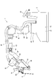
- FIG. 4 is a perspective view showing the configuration of an arm operation section according to the embodiment
- FIG. 3 is a perspective view showing the configuration of an operation arm of the remote control device according to the embodiment
- FIG. 3 is a perspective view showing the configuration of an operation arm and an operation handle according to this embodiment
- 1 is a perspective view (1) showing the configuration of an operating handle according to the present embodiment
- FIG. 2 is a perspective view (2) showing the configuration of the operating handle according to the present embodiment
- FIG. 4 is a side view showing the configuration of the operating handle according to the embodiment; 3 is an exploded perspective view for explaining the configuration of the switch according to the embodiment;
- FIG. 1 is a cross-sectional view (1) for explaining the configuration of a switch according to this embodiment;
- FIG. FIG. 2 is a cross-sectional view (2) for explaining the configuration of the switch according to the present embodiment; It is a perspective view which shows the operation pedal by this embodiment.
- FIG. 10 is a diagram showing a setting screen for setting functions of the third switch;
- FIG. 10 is a diagram for explaining a pivot distance display;
- FIG. FIG. 4 is a diagram for explaining a screen layout;
- FIG. Fig. 3 shows areas of a graphical user interface;
- FIG. 1 shows an image captured by an endoscope and a graphical user interface
- FIG. 4 is a diagram for explaining a first graphical display
- FIG. 11 is a diagram for explaining a second graphical display
- FIG. It is a figure for demonstrating the display of the touch panel of a remote control. It is a figure which shows the processing flow of a control apparatus. It is a figure for demonstrating the setting screen by a modification.
- FIG. 1 The configuration of a surgical system 100 according to this embodiment will be described with reference to FIGS. 1 to 21.
- FIG. 1 The configuration of a surgical system 100 according to this embodiment will be described with reference to FIGS. 1 to 21.
- FIG. 1 The configuration of a surgical system 100 according to this embodiment will be described with reference to FIGS. 1 to 21.
- FIG. 1 The configuration of a surgical system 100 according to this embodiment will be described with reference to FIGS. 1 to 21.
- a surgical operation system 100 includes a medical manipulator 1 as a patient-side device, a remote control device 2 as an operator-side device for operating the medical manipulator 1, a control device 8, and an image processing unit 9 .
- the medical manipulator 1 has a medical cart 3 and is configured to be movable.
- the remote control device 2 is arranged at a position separated from the medical manipulator 1 , and the medical manipulator 1 is configured to be remotely controlled by the remote control device 2 .
- the operator inputs a command to the remote control device 2 to cause the medical manipulator 1 to perform a desired operation.
- the remote control device 2 transmits the input command to the medical manipulator 1 .
- the medical manipulator 1 operates based on the received commands.
- the medical manipulator 1 is arranged in the operating room, which is a sterile sterile field.
- the surgical operation system 100 is an example of a surgical operation support system.
- the medical manipulator 1 and the remote control device 2 are examples of a patient-side device and an operator-side device, respectively.
- the remote control device 2 is arranged inside or outside the operating room, for example.
- the remote control device 2 includes an operation manipulator 21, an operation pedal 22, a touch panel 23, a monitor 24, a support arm 25, a support bar 26, and an error reset button 26a.
- the operating manipulator 21 constitutes an operating handle for the operator to input commands.
- the manipulation manipulator 21 receives manipulation amounts for the medical instrument 4 .
- the monitor 24 is a scope-type display device that displays an image GR21 captured by the endoscope 4b.
- the support arm 25 supports the monitor 24 so that the height of the monitor 24 matches the height of the operator's face.
- the touch panel 23 is arranged on the support bar 26 .
- the medical manipulator 1 can be operated by the remote control device 2 by detecting the operator's head with a sensor provided near the monitor 24 .
- the operator operates the operation manipulator 21 and the operation pedal 22 while viewing the affected area on the monitor 24 . Accordingly, a command is input to the remote control device 2 .
- a command input to the remote control device 2 is transmitted to the medical manipulator 1 .
- the operation manipulator 21 includes a right-hand operation manipulator 21R and a left-hand operation manipulator 21L.
- An error reset button 26 a is arranged on the support bar 26 . Error reset button 26a clears an error in surgical system 100.
- the medical device 4 is an example of a first medical device and a second medical device.
- the operating manipulator 21 is an example of an operating arm.
- the touch panel 23 is an example of a function setting display unit.
- the monitor 24 is an example of a first display section.
- the control device 8 and the image processing unit 9 are placed on the cart 8a.
- the image processing unit 9 processes the image GR21 taken by the endoscope 4b.
- a display unit 8b is arranged on the cart 8a. In this embodiment, the display unit 8b is arranged independently of the medical manipulator 1 and the remote control device 2.
- FIG. An image GR21 captured by the endoscope 4b is displayed on the display unit 8b.
- the controller 8 is provided with an error reset button 8c and a notification section 8d.
- the error reset button 8c clears the surgical system 100 error.
- the display portion 8b is an example of a second display portion.
- the medical trolley 3 includes a control unit 31 for controlling the operation of the medical manipulator 1 and a storage unit for storing programs for controlling the operation of the medical manipulator 1. 32 are provided.
- the controller 31 of the medical cart 3 controls the operation of the medical manipulator 1 based on the command input to the remote controller 2 .
- the medical cart 3 is provided with an input device 33 .
- the input device 33 is configured to receive operations for moving and changing postures of the positioner 40, the arm base 50, and the plurality of arms 60, mainly for preparing for surgery before surgery.
- the input device 33 is provided with an error reset button 33a.
- the error reset button 33a clears the surgical system 100 error.
- the medical manipulator 1 shown in FIGS. 1 and 2 is arranged in an operating room.
- the medical manipulator 1 includes a medical cart 3 , a positioner 40 , an arm base 50 and a plurality of arms 60 .
- Arm base 50 is attached to the tip of positioner 40 .
- Arm base 50 has a relatively long rod shape.
- the plurality of arms 60 are attached to the arm base 50 at the root portion of each arm 60 .
- the plurality of arms 60 are configured to be able to take a folded storage posture.
- the arm base 50 and the plurality of arms 60 are covered with a sterile drape before use.
- the positioner 40 is composed of, for example, a 7-axis articulated robot. Also, the positioner 40 is arranged on the medical cart 3 . Positioner 40 moves arm base 50 . Specifically, the positioner 40 is configured to move the position of the arm base 50 three-dimensionally.
- the positioner 40 also includes a base portion 41 and a plurality of link portions 42 connected to the base portion 41 .
- the plurality of link portions 42 are connected by joint portions 43 .
- a medical instrument 4 is attached to the tip of each of the plurality of arms 60 .
- Medical instruments 4 include, for example, replaceable instruments 4a and endoscopes 4b.
- the arm 60 is an example of a robot arm.
- the arm 60 includes an arm portion 61 and a translational movement mechanism portion 70 provided at the tip of the arm portion 61 .
- the arm 60 is configured to three-dimensionally move the tip side with respect to the arm base 50 at the base of the arm 60 .
- Arm 60 has eight degrees of freedom. Specifically, the arm 60 has axes from the JT1 axis to the JT7 axis as rotation axes, and the JT8 axis as a linear movement axis.
- the plurality of arms 60 have the same configuration as each other.
- the arm portion 61 includes a base portion 62 , a link portion 63 and a joint portion 64 .
- the translational movement mechanism section 70 is provided at the tip of the arm section 61 and has the medical instrument 4 attached thereto. Further, the translational movement mechanism section 70 translates the medical instrument 4 in the direction of inserting it into the patient P placed on the operating table 5 . Further, the translational movement mechanism section 70 is configured to relatively translate the medical device 4 with respect to the arm section 61 . Specifically, the translational movement mechanism section 70 is provided with a holder 71 that holds the medical instrument 4 . A servo motor is accommodated in the holder 71 . The servomotor is configured to rotate a rotating body provided in the driven unit 4aa of the medical instrument 4. As shown in FIG. The medical device 4 operates by rotating the rotating body of the driven unit 4aa.
- the arm part 61 is composed of a 7-axis articulated robot arm.
- Arm portion 61 also includes a base portion 62 for attaching arm portion 61 to arm base 50 and a plurality of link portions 63 connected to base portion 62 .
- the plurality of link portions 63 are connected by joint portions 64 .
- the translational movement mechanism 70 is configured to translate the medical device 4 attached to the holder 71 along the direction A, which is the direction in which the shaft 4ab extends, by translating the holder 71 along the direction A. ing.
- the translational movement mechanism section 70 includes a proximal side link section 72 connected to the distal end of the arm section 61 , a distal side link section 73 , and a joint between the proximal side link section 72 and the distal side link section 73 . and a connecting link portion 74 provided therebetween.
- the holder 71 is provided on the tip side link portion 73 .
- the connecting link portion 74 of the translational movement mechanism portion 70 is configured as a double-speed mechanism that relatively moves the distal side link portion 73 along the A direction with respect to the proximal side link portion 72 . Further, the medical device 4 attached to the holder 71 translates along the A direction by moving the distal side link portion 73 relative to the proximal side link portion 72 along the A direction. is configured as Further, the distal end of the arm portion 61 is connected to the proximal link portion 72 so as to rotate the proximal link portion 72 about the B direction orthogonal to the A direction.
- one of the plurality of arms 60 is attached with an endoscope 4b, and the remaining arms 60a, 60b, and 60d are attached with components other than the endoscope 4b.
- An instrument 4a which is a medical device 4, is attached.
- the pivot position PP is taught with the endoscope 4b attached to the arm 60 to which the endoscope 4b is attached.
- the pivot position PP is taught in a state where the pivot position teaching instrument is attached to the arm 60 to which the instrument 4a other than the endoscope 4b is attached.
- the endoscope 4b is attached to one of the two centrally arranged arms 60b and 60c of the four arms 60 arranged adjacent to each other.
- the pivot position PP is set individually for each of the multiple arms 60 .
- Arms 60a, 60b and 60d are examples of a first medical instrument robotic arm and a second medical instrument robotic arm.
- the arm 60c is an example of an endoscope robot arm.
- the arm operating section 80 is attached to the arm 60. Specifically, the arm operation section 80 is attached to the distal link section 73 .
- the arm operating section 80 includes an enable switch 81, a joystick 82, a linear switch 83, a mode switching button 84, a mode indicator 84a, a pivot button 85, and an adjustment button 86. include.
- the enable switch 81 is a switch that permits or disallows movement of the arm 60 by the joystick 82 and linear switch 83 .
- the joystick 82 is an operating tool for operating the movement of the medical device 4 by the arm 60 .
- the linear switch 83 is a switch for moving the medical device 4 along the longitudinal direction of the medical device 4 .
- the mode switching button 84 is a button for switching between a mode in which the medical instrument 4 is translated and a mode in which it is rotated.
- a mode indicator 84a displays the switched mode.
- the pivot button 85 is a button for teaching the pivot position PP, which is the fulcrum of movement of the medical instrument 4 attached to the arm 60 .
- Adjustment button 86 is a button for optimizing the position of arm 60 .
- the operation manipulator 21 is arranged on the left side of an operator such as an operator, and an operation manipulator 21L is operated by the left hand of the operator, and is arranged on the right side by the operator. and an operating manipulator 21R operated by the right hand.
- the manipulator 21L for operation and the manipulator 21R for operation are the same except that the operation part 21b has a symmetrical structure.
- the operating manipulator 21 includes an operating arm 21a and an operating portion 21b.
- the operating arm 21a has a link portion 21aa, a link portion 21ab, and a link portion 21ac.
- the upper end side of the link portion 21aa is attached to the main body of the remote control device 2 so as to be rotatable around the A1 axis along the vertical direction.
- the upper end side of the link portion 21ab is attached to the lower end side of the link portion 21aa so as to be rotatable around the A2 axis along the horizontal direction.
- One end side of the link portion 21ac is attached to the lower end side of the link portion 21ab so as to be rotatable around the A3 axis along the horizontal direction.
- the operation arm 21a supports the operation portion 21b so as to be movable within a predetermined three-dimensional operation range. Specifically, the operating arm 21a supports the operating portion 21b so as to be movable in the vertical direction, the horizontal direction, and the front-rear direction. The arm 60 is moved three-dimensionally so as to correspond to the three-dimensional operation of the operating arm 21a.
- the operation portion 21b of the right-hand operation manipulator 21R has a link portion 21ad, a link portion 21ae, a link portion 21af, and an operation handle 321b.
- One end side of the link portion 21ad is attached to the other end side of the link portion 21ac so as to be rotatable about the A4 axis.
- One end side of the link portion 21ae is received by the other end side of the link portion 21ad so as to be rotatable about the A5 axis.
- One end side of the link portion 21af is attached to the other end side of the link portion 21ae so as to be rotatable about the A6 axis.
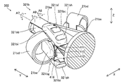
- the operating handle 321b has a support member 21ba, a first lever member 321bb, and a second lever member 321bc.
- the first lever member 321bb is an example of a lever member.
- the first lever member 321bb has an elongated plate-like shape and is attached so as to rotate with respect to the support member 21ba.
- the first lever member 321bb is attached to the supporting member 21ba so as to rotate about an A9 axis perpendicular to the A7 axis.
- the first lever member 321bb is arranged to face the second lever member 321bc via the support member 21ba.
- the second lever member 321bc has an elongated plate-like shape and is attached so as to rotate with respect to the support member 21ba.
- the second lever member 321bc is attached to the support member 21ba so as to rotate about an A8 axis perpendicular to the A7 axis.
- the second lever member 321bc is arranged to face the first lever member 321bb via the support member 21ba.
- a finger insertion portion 21bd and a finger pad 21be are arranged on the first lever member 321bb and the second lever member 321bc.
- the operating handle 321b further has a first switch 321bf attached to the first lever member 321bb and performing a predetermined function.
- the first switch 321bf is a clutch switch that performs a clutch function that does not transmit the operation of the operator to the medical manipulator 1 .
- the first lever member 321bb and the second lever member 321bc are closed.
- the first switch 321bf is operated with the index finger of the right hand that does not operate the first lever member 321bb and the second lever member 321bc.
- the first switch 321bf is arranged at a position closer to the distal end than the proximal end of the first lever member 321bb. Specifically, the first switch 321bf is arranged at the distal end of the first lever member 321bb. The first switch 321bf is arranged at the first end 411 of the first end 411 and the second end 412 of the first lever member 321bb in the Z direction parallel to the A9 axis. Note that the first end portion 411 is a portion of the distal end of the first lever member 321bb on one side in the Z direction parallel to the A9 axis. Also, the second end portion 412 is the other end portion of the distal end of the first lever member 321bb, which is opposite to the first end portion 411 in the Z direction parallel to the A9 axis.
- the operating handle 321b further has a second switch 321bg that is attached to the first lever member 321bb and performs a predetermined function.
- a first switch 321bf and a second switch 321bg are arranged on the first lever member 321bb.
- the second switch 321bg has the same function as the first switch 321bf.
- the second switch 321bg is a clutch switch that performs a clutch function that does not transmit the operation of the operator to the medical manipulator 1 .
- the first lever member 321bb with the index finger of the right hand and operates the second lever member 321bc with the thumb of the right hand
- the operator supports the first lever member 321bb and the second lever member 321bc.
- the second switch 321bg With the member 21ba in the closed state (the state shown in FIG. 8), the second switch 321bg is operated with the middle finger of the right hand that does not operate the first lever member 321bb and the second lever member 321bc.
- the second switch 321bg is arranged at a position closer to the distal end than the proximal end of the first lever member 321bb. Specifically, the second switch 321bg is located at the distal end of the first lever member 321bb. The second switch 321bg is arranged at the second end 412 of the first end 411 and the second end 412 of the first lever member 321bb in the Z direction parallel to the A8 axis. That is, the second switch 321bg is arranged at the second end 412 opposite to the first switch 321bf.
- the first switch 321bf and the second switch 321bg are arranged at symmetrical positions with the first lever member 321bb interposed in the Z direction parallel to the A8 axis and the A9 axis.
- the first switch 321bf is operated with the index finger of the right hand not operating the first lever member 321bb.
- the middle finger of the right hand not operating the first lever member 321bb is used to operate the first switch 321bf. It is possible. As a result, it is possible to accommodate both an operator who operates the first lever member 321bb with the middle finger of the right hand and an operator who operates the first lever member 321bb with the index finger of the right hand.
- the first switch 321bf and the second switch 321bg overlap the support member 21ba in the Z direction parallel to the A8 and A9 axes in a state where the first lever member 321bb is closed with respect to the support member 21ba. It is placed in a position where Therefore, when the first lever member 321bb is closed with respect to the support member 21ba and the support member 21ba is rotated by 180 degrees around the A7 axis, the first switch 321bf is placed at the position of the second switch 321bg. and the second switch 321bg is placed at the position of the first switch 321bf. This allows the first switch 321bf and the second switch 321bg to be similarly operated even when the support member 21ba is rotated 180 degrees around the A7 axis.
- the first lever member 321bb is attached to a facing surface 415 facing the supporting member 21ba of the first lever member 321bb, and the supporting surface perpendicular to the facing surface 415 is mounted. It includes a plate-shaped mounting member 416 that supports the first switch 321bf and the second switch 321bg.
- the mounting member 416 moves integrally with the first lever member 321bb according to the rotation of the first lever member 321bb.
- the mounting member 416 includes a first flat plate portion 416a parallel to the facing surface 415, and two second flat plate portions 416b connected to the first flat plate portion 416a so as to be bent perpendicularly to the first flat plate portion 416a.
- the two second flat plate portions 416b are respectively connected to one side and the other side of the first flat plate portion 416a in the Z direction parallel to the A8 axis and the A9 axis.
- a first switch 321bf and a second switch 321bg are attached to one and the other of the two second flat plate portions 416b, respectively, in opposite directions.
- the two second flat plate portions 416b support the first switch 321bf and the second switch 321bg on supporting surfaces perpendicular to the facing surface 415.
- the second flat plate portion 416b is arranged to extend from the first flat plate portion 416a to the side close to the support member 21ba. Note that the mounting member 416 is not provided on the second lever member 321bc.
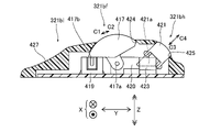
- the first switch 321bf and the second switch 321bg are roller switches that are operated by the operator by rotating them with their fingers.
- a first switch 321bf and a second switch 321bg which are roller switches, are a rotating body 417 that is operated by an operator to rotate it with a finger, and a biasing force that biases the rotating body 417 to the initial position (the position shown in FIG. 19).
- a portion 418 and a sensor 419 that detects movement of the rotating body 417 are included. 19 and 20, only the first switch 321bf is shown for convenience.
- the rotating body 417 has a sector shape and an arcuate curved operation surface.
- the operating surface of the rotating body 417 slightly protrudes from an opening 424 of a switch housing 321bi, which will be described later.
- the rotating body 417 is supported by a supporting portion 420 to which the rotating shaft 417a is attached via the rotating shaft 417a so as to rotate about the rotating shaft 417a.
- Rotating body 417 rotates around rotating shaft 417a between an initial position (position shown in FIG. 11) where it is not detected by sensor 419 and a detection position (position shown in FIG. 12) where it is detected by sensor 419. .
- the rotating body 417 has a detected portion 417 b that is detected by the sensor 419 .
- the detected portion 417b has a convex shape protruding toward the sensor 419 side.
- the biasing portion 418 is an elastic member that biases the rotor 417 to the initial position. Specifically, biasing portion 418 is a compression coil spring.
- the sensor 419 is a transmissive photosensor having a light-emitting portion and a light-receiving portion.
- the rotating body 417 moves against the urging force of the urging portion 418 and moves toward the rotation axis. It is rotated to the detection position along the rotation direction C1 around 417a. At this time, the detected portion 417b of the rotating body 417 is inserted between the light emitting portion and the light receiving portion of the sensor 419, and light from the light emitting portion to the light receiving portion is blocked. Then, the rotating body 417 is detected by the sensor 419 . This state is the ON state. In the ON state, the clutch function is executed.
- the rotating body 417 is rotated by the biasing force of the biasing portion 418 in the rotating direction C2 opposite to the rotating direction C1 around the rotating shaft 417a. to the initial position.
- the detected portion 417b of the rotating body 417 is pulled out from between the light emitting portion and the light receiving portion of the sensor 419, and the blocking of light from the light emitting portion to the light receiving portion is released, allowing light to pass through.
- the rotating body 417 is no longer detected by the sensor 419 .
- This state is the off state. In the OFF state, the clutch function is not executed.
- a first switch 321bf and a third switch 321bh are arranged on the operating portion 21b, as shown in FIGS.
- the third switch 321bh is a customization switch that customizes the function to be executed by setting the function.
- the first switch 321bf and the third switch 321bh are arranged on the first lever member 321bb.
- the third switch 321bh is set with functions related to surgery on the patient P, such as image switching and camera zoom. The details of the setting of the functions to the third switch 321bh will be described later.
- the third switch 321bh is an example of a customized switch.
- the third switch 321bh is arranged to be inclined with respect to the first switch 321bf. Specifically, the third switch 321bh is arranged so as to be inclined with respect to the Y direction, which is the longitudinal direction of the support member 21ba. Also, the third switch 321bh is arranged farther than the first switch 321bf.
- the third switch 321bh is of a push button type operated by the operator by pressing it with his/her finger.
- the push-button third switch 321bh includes an operating body 421 operated by the operator by pressing it with a finger, a biasing portion 422 that biases the operating body 421 to the initial position (the position shown in FIG. 11), and a sensor 423 that detects movement of the body 421 .
- 11 and 12 show a state in which both the first switch 321bf and the third switch 321bh are operated for the sake of convenience, it is necessary to simultaneously operate both the first switch 321bf and the third switch 321bh. Instead, the first switch 321bf and the third switch 321bh can be operated independently of each other.
- the operation body 421 has an operation surface inclined with respect to the first switch 321bf. An operation surface of the operation body 421 protrudes in an inclined direction from an opening 425 of a switch housing 321bi, which will be described later. Further, the operating body 421 is supported so as to move in the tilt direction. The operating body 421 moves in the tilt direction between an initial position (position shown in FIG. 11) where it is not detected by the sensor 423 and a detection position (position shown in FIG. 12) where it is detected by the sensor 423 .
- the operating body 421 also has a detected portion 421 a that is detected by the sensor 423 .
- the detected portion 421a has a convex shape protruding toward the sensor 423 side.
- the biasing portion 422 is an elastic member that biases the operating body 421 to the initial position. Specifically, the biasing portion 422 is a compression coil spring.
- the sensor 423 is a transmissive photosensor having a light emitting portion and a light receiving portion.
- the operating body 421 when the operating surface of the operating body 421 is operated by the operator's finger so as to push the operating body 421 , the operating body 421 is tilted in the tilt direction C ⁇ b>3 while resisting the biasing force of the biasing portion 422 . is moved linearly along to the detection position. At this time, the detected portion 421a of the operating body 421 is inserted between the light emitting portion and the light receiving portion of the sensor 423, and light from the light emitting portion to the light receiving portion is blocked. Then, the operating body 421 is detected by the sensor 423 . This state is the ON state. Then, the function set in the third switch 321bh is executed.
- the operation body 421 is moved by the biasing force of the biasing portion 422 along the tilt direction C4 opposite to the tilt direction C3 to the initial position. moved in a straight line.
- the detected portion 421a of the operating body 421 is pulled out from between the light emitting portion and the light receiving portion of the sensor 423, and the blocking of light from the light emitting portion to the light receiving portion is released, allowing light to pass through.
- the operating body 421 is no longer detected by the sensor 423 . This state is the off state. Then, the function set to the third switch 321bh is not executed.
- the ON state and the OFF state of the third switch 321bh may be reversed. That is, it may be turned off when the operating body 421 is detected by the sensor 423 and turned on when the operating body 421 is not detected by the sensor 423 . Further, the third switch 321bh may be switched between the ON state and the OFF state each time the operating body 421 is detected by the sensor 423 .
- the third switch 321bh and the first switch 321bf are arranged in one switch housing 321bi.
- the switch housing 321bi constitutes a finger rest on which the operator's finger is placed.
- the switch housing 321bi is arranged on a first lever member 321bb that is operated by an operator's index finger or middle finger. That is, in this embodiment, the remote control device 2 includes a finger rest attached to the first lever member 321bb and on which the operator's finger is placed.
- the switch housing 321bi is an example of a housing.
- the switch housing 321bi covers the first switch 321bf and the third switch 321bh from one side in the Z direction parallel to the A8 and A9 axes.
- the switch housing 321bi has a shape extending in the Y direction, which is the longitudinal direction of the support member 21ba.
- the switch housing 321bi also has an opening 424 in which the first switch 321bf is arranged and an opening 425 in which the third switch 321bh is arranged.
- the switch housing 321bi has a side surface portion 426 and an inclined surface portion 427 as portions that function as finger rests.
- the side portion 426 is a side portion arranged on the first lever member 321bb side of the switch housing 321bi in the X direction, and is arranged in the Z direction parallel to the A8 and A9 axes and in the Y direction, which is the longitudinal direction of the support member 21ba. extended.
- the operator can rest the index finger of the right hand, which is not operating the first lever member 321bb, from the side in a state where the middle finger of the right hand is placed on the first lever member 321bb. is.
- the inclined surface portion 427 is arranged proximal to the openings 424 and 425 in the Y direction and is inclined with respect to the Y direction. Specifically, the inclined surface portion 427 is inclined so as to be depressed from one side toward the other side in the Z direction. In a state where the operator places the middle finger of the right hand on the first lever member 321bb, the operator places the forefinger of the right hand, which is not operating the first lever member 321bb, on the inclined surface portion 427 from one side in the Z direction and rests. It is possible. Note that both the side surface portion 426 and the inclined surface portion 427 are portions of the switch housing 321bi where the first switch 321bf and the third switch 321bh are not arranged. There is no risk of erroneous operation of the first switch 321bf and the third switch 321bh even if the switch is placed and rested.
- a third switch 321bh is also arranged for the second switch 321bg.
- the configurations of the third switch 321bh and the switch housing 321bi regarding the second switch 321bg are the same as the configurations of the third switch 321bh and the switch housing 321bi regarding the first switch 321bf.
- the switch housing 321bi arranged with respect to the second switch 321bg allows the operator's finger to rest thereon as follows. That is, when the operator places the middle finger of the right hand on the first lever member 321bb, the third finger of the right hand, which is not operating the first lever member 321bb, can be rested on the side surface 426 from the side. is possible. In addition, when the operator places the index finger of the right hand on the first lever member 321bb, the middle finger of the right hand, which is not operating the first lever member 321bb, can be placed on the side surface 426 from the side and rested. is possible.
- first switch 321bf, the second switch 321bg, and the third switch 321bh provided on the operation handle 321b of the right-hand manipulator 21R have been described. It has the same structure as the operation handle 321b of the right-hand manipulator 21R, except that it has a bilaterally symmetrical structure.
- the first switch 321bf of the right-hand manipulator 21R and the first switch 321bf of the left-hand manipulator 21L operate the arm 60 operated by the right-hand manipulator 21R and the left-hand manipulator 21R. Arm 60 operated by manipulator 21L may be able to be clutched independently of each other.
- the arm 60 operated by the right-hand manipulator 21R is clutched, and the first switch 321bf of the left-hand manipulator 21L is turned on.
- the arm 60 operated by the left hand operating manipulator 21L may be clutched.
- the operation pedal 22 operated by the operator's foot will be described.
- a plurality of operation pedals 22 are provided to perform functions related to the medical instrument 4 .
- the operation pedal 22 includes a switching pedal 22a, a clutch pedal 22b, a camera pedal 22c, an incision pedal 22d, and a coagulation pedal 22e.
- the switching pedal 22a, the clutch pedal 22b, the camera pedal 22c, the incision pedal 22d, and the coagulation pedal 22e are operated by the operator's foot.
- the incision pedals 22 d also include an incision pedal 22 dR for the right arm 60 and an incision pedal 22 dL for the left arm 60 .
- Coagulation pedals 22 e also include a coagulation pedal 22 e R for right arm 60 and a coagulation pedal 22 e L for left arm 60 .
- the switching pedal 22a switches the arm 60 operated by the operating portion 21b.
- the clutch pedal 22b performs a clutch function that does not transmit the operator's operation to the medical manipulator 1 . While the operator is stepping on the clutch pedal 22b, the operation of the operating portion 21b is not transmitted to the arm 60. Further, while the operator is stepping on the camera pedal 22c, the operating portion 21b enables the arm 60 to which the endoscope 4b is attached to be operated. While the dissection pedal 22d or coagulation pedal 22e is depressed by the operator, the electrosurgical device is activated.
- the first switch 321bf performs a function different from the clutch function, which is a predetermined function, by being operated simultaneously with the camera pedal 22c. Specifically, the first switch 321bf performs a function related to the image GR21 captured by the endoscope 4b by being operated simultaneously with the camera pedal 22c. Also, when the first switch 321bf is operated at the same time as the camera pedal 22c, it performs different functions depending on how the first switch 321bf is operated. More specifically, when the first switch 321bf is operated simultaneously with the camera pedal 22c, it performs different functions according to at least one of the operation time of the first switch 321bf and the number of operations of the first switch 321bf.
- the first switch 321bf when the first switch 321bf is operated at the same time as the camera pedal 22c, if the first switch 321bf is pressed for a predetermined period of time or longer, an image GR21 captured by the endoscope 4b is displayed. Execute the function to switch between For example, in an operation performed by administering indocyanine green (ICG), which is a fluorescent substance, to a patient P, an ICG fluorescence image and a normal image other than the ICG fluorescence image are switched.
- ICG indocyanine green
- the endoscope 4b executes the function of zooming in on the image GR21.
- the endoscope 4b executes the function of zooming out the image GR21 to be displayed.
- the right-hand first switch 321bf and the left-hand first switch 321bf may have different functions to be executed when they are simultaneously operated with the camera pedal 22c.
- the camera pedal 22c and the right-hand first switch 321bf are operated at the same time, the camera pedal 22c and the left-hand first switch 321bf are operated to perform a function of zooming in on the image GR21 captured by the endoscope 4b.
- 321bf are operated at the same time, a function of zooming out the image GR21 captured by the endoscope 4b may be executed.
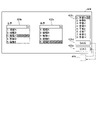
- the touch panel 23 of the remote control device 2 displays a setting screen 500 for setting the function of the third switch 321bh.
- the setting screen 500 has a function selection field 501 for the right hand third switch 321bh and a function selection field 502 for the left hand third switch 321bh.
- the processing for displaying the setting screen 500 is executed by the control device 8 .
- the setting screen 500 displays a plurality of predetermined functions.
- a function selected by the operator from among a plurality of functions is set to the third switch 321bh.
- the control device 8 performs processing for displaying a plurality of predetermined functions on the setting screen 500 .
- a function selection field 501 is a field for selecting a function to be set to the right third switch 321bh.
- a plurality of functions to be set to the third switch 321bh on the right are displayed in a pull-down format so that they can be selected.
- An arbitrary function selected by the operator from among a plurality of functions displayed in a pull-down format in the function selection field 501 is set to the right third switch 321bh.
- the process of setting the function to the right third switch 321bh is executed by the control device 8 .
- the function selection field 502 is a field for selecting a function to be set to the left hand third switch 321bh.
- a plurality of functions to be set to the third switch 321bh on the left are displayed in a pull-down format so that they can be selected.
- An arbitrary function selected by the operator from among a plurality of functions displayed in a pull-down format in the function selection field 502 is set to the left hand third switch 321bh.
- the process of setting the function to the third switch 321bh on the left hand is executed by the control device 8 .
- the surgical system 100 includes the storage section 32 shown in FIG.
- the previously set function is read from the storage unit 32 and set to the third switch 321bh. That is, when a function is set for the third switch 321bh on the touch panel 23, the set function is stored in the storage unit 32.
- the control device 8 executes the process of setting the function stored in the storage unit 32 to the third switch 321bh.
- the control device 8 executes the function set to the third switch 321bh.
- the functions set in the third switch 321bh include the function of displaying the distance between the pivot positions PP, which are the fulcrums of movement of the medical instruments 4 attached to the plurality of arms 60, on the display unit.
- the distance between the pivot position PP is the monitor 24 arranged in the remote control device 2 for displaying the image GR21 taken by the endoscope 4b and the display unit 8b for displaying the image GR21 taken by the endoscope 4b. and is displayed in The same image is displayed on the monitor 24 and the display section 8b.
- the process of displaying the distance between the pivot positions PP on the monitor 24 and the display unit 8b is executed by the control device 8.
- pivot positions PP are set for the plurality of arms 60 .
- the control device 8 executes a process of displaying a marker MK11 indicating the arm 60 corresponding to the endoscope 4b and a marker MK12 corresponding to the medical instrument 4 other than the endoscope 4b on the monitor 24 and the display unit 8b.
- the distance between the pivot positions PP of each arm 60 is indicated between the marks MK11 and MK12 or between the marks MK12, for example, in cm.
- the distance between the pivot positions PP is displayed after setting the pivot positions PP and before the following operation.
- a following operation is an operation in which the arm 60 is moved by operating the operating portion 21b by the operator.
- the distance between the pivot positions PP is not displayed while the enable switch 81 of the arm operation unit 80 is pressed.
- the third switch 321bh By turning on the third switch 321bh, the distance between the pivot positions PP is displayed on the monitor 24 and the display section 8b.
- the display of the distance between the pivot positions PP on the monitor 24 and the display section 8b is turned off.
- the functions set to the third switch 321bh are to display an image GR21 captured by the endoscope 4b on the monitor 24 and the display unit 8b in full screen, It includes a function of switching between displaying the image GR21 and the image GR22 input from the outside side by side on the monitor 24 and the display unit 8b.
- the process of switching between displaying the image GR21 on the full screen and displaying the image GR21 and the image GR22 input from the outside side by side is executed by the control device 8 .
- the image GR22 includes an image input from an external device 8e connected to the control device 8 that processes the image GR21 captured by the endoscope 4b.
- the external device 8e is, for example, an external storage device such as a USB (registered trademark) memory, a medical imaging device such as a CT device and an MRI device, and the like.
- An image input from the external device 8e is an examination image of the patient P, for example.
- the functions set to the third switch 321bh are to display an image GR21 captured by the endoscope 4b on the monitor 24 and the display unit 8b in full screen, Switch between displaying the image GR21 and the image GR22 side by side in the horizontal direction on the monitor 24 and the display unit 8b and displaying the image GR21 and the image GR22 side by side in the vertical direction on the monitor 24 and the display unit 8b.
- Including function The process of switching between displaying the image GR21 on the full screen, displaying the image GR21 and the image GR22 side by side in the horizontal direction, and displaying the image GR21 and the image GR22 side by side in the vertical direction is controlled by the control.
- FIG. 16 shows a screen displayed on the touch panel 23 of the remote control device 2, and the screen layout can be switched by the touch panel 23 as well.
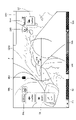
- the control device 8 generates a graphical user interface G, and as shown in FIG. 18, superimposes the graphical user interface G on the image GR21 captured by the endoscope 4b. is displayed on the monitor 24 and the display unit 8b.
- the control device 8 captures an image GR21 from the endoscope 4b. Further, the control device 8 acquires information on the operable range of the arm 60 and information on the current position of the arm 60 from the arm control section 31a. In addition, the control device 8 acquires information on the operable range of the operation unit 21b and information on the current position of the operation unit 21b from the remote operation device 2 .
- the graphical user interface G shows the state of the clutch pedal 22b.
- the graphical user interface G includes a camera area G2.
- the camera area G2 displays the state of the camera pedal 22c.
- the graphical user interface G includes a hand area G3.
- the hand area G3 displays the state of each arm 60 and the states of the coagulation pedal 22e and the incision pedal 22d.
- the clutch area G1, the camera area G2, and the hand area G3 are displayed on the lower side of the monitor 24.
- the graphical user interface G includes a medical instrument area G4.
- the medical device area G4 displays the current number of times of use/maximum number of times of use of the medical device 4 attached to each arm 60 .
- the current number of uses equals the maximum number of uses, the current number of uses is displayed in red.
- the medical instrument area G4 is displayed on the monitor 24 above the clutch area G1, the camera area G2, and the hand area G3.
- the graphical user interface G includes a spirit level area G5.
- the level area G5 displays angle information of the endoscope 4b. Also, the spirit level area G5 is displayed only while the camera pedal 22c is depressed.
- the graphical user interface G includes a left popup area G6. Icons are displayed in the left popup area G6 in a hover state in which the foot is placed on the operation pedal 22 .
- the graphical user interface G includes a right popup area G7.
- icons are displayed when the foot is placed on the coagulation pedal 22eR and the incision pedal 22dR.
- the right popup area G7 is displayed on the right side of the monitor 24 .
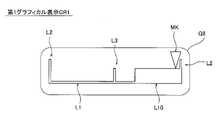
- the graphical user interface G displays the operable range of the arm 60, and the operable range of the operable range of the arm 60 that can be operated by the operating section 21b. It includes a first area G8 displaying one graphical representation GR1. In addition, the graphical user interface G indicates the operation of the operation unit 21b required for at least one of returning the operation unit 21b within the operable range and returning the arm 60 within the operable range. It includes a second area G9, different from the first area G8, displaying a second graphical representation GR2 shown in FIG.
- the function set in the third switch 321bh is to display the operable range of the arm 60 and the first graphical display GR1 indicating the operable range of the operable range of the arm 60 that can be operated by the operation unit 21b. It includes a function of displaying a graphical user interface G having a first area G8 to be displayed on the monitor 24 and the display unit 8b.
- the function set in the third switch 321bh is an operation necessary for at least one of returning the operating portion 21b within the operable range and returning the arm 60 within the operable range.
- It includes a function of displaying, on the monitor 24 and the display section 8b, a graphical user interface G having a second area G9 different from the first area G8, which displays a second graphical display GR2 indicating the operation of the section 21b.
- the second graphical display GR2 indicates the operation of the operation unit 21b required for both returning the operation unit 21b within the operable range and returning the arm 60 within the operable range.
- a graphical user interface G having a first area G8 displaying the first graphical display GR1 is displayed on the monitor 24 and the display unit 8b
- the graphical user interface G displaying the second graphical display GR2 is displayed on the monitor 24 and the display unit 8b.
- the process displayed on the part 8 b is executed by the control device 8 .
- the third switch 321bh By turning on/off the third switch 321bh, the first graphical display GR1 and the second graphical display GR are switched between a displayed state and a non-displayed state.
- the process of switching between the displayed state and the non-displayed state is executed by the control device 8 .
- the movable range of the arm 60 means the movable range of the axis that rotates the shaft 4c among the axes from the JT9 axis to the JT12 axis of the arm 60, and rotates 270° in the positive and negative directions.
- the operable range of the operating portion 21b means the movable range of the A7 axis (JT7 axis), which rotates 270° in the positive and negative directions.
- the operable range of the arm 60 and the operable range of the operating portion 21b are represented by the length of the lines.
- the movable range of the arm 60 is represented on the monitor 24 by the length of a line L1 extending in the horizontal direction.
- Boundary lines L2 extending in the vertical direction are provided at both ends of the line L1 extending in the horizontal direction.
- the indication of the range of motion of arm 60 further includes a vertically extending line L3 indicating the center of the range of motion.
- the operable range of the operating portion 21b is represented by a line L10 extending in the horizontal direction.
- the current position of the arm 60 is represented by a triangular marking MK.
- the second graphical display GR2 is displayed when the angle to the limit of the operable range of the operation unit 21b becomes equal to or less than the first threshold value and when the angle to the limit of the operable range of the arm 60 is displayed. Displayed when the angle is less than or equal to the second threshold.
- the first threshold and the second threshold are, for example, 10 degrees.
- the second graphical display GR2 indicates the direction in which the operation unit 21b is rotated.
- the direction in which the operating portion 21b is rotated is represented by an arc a1 and an arrow a2 provided at the tip of the arc a1.
- the second area G9 further displays the angle for rotating the operation unit 21b.
- the second area G9 further displays a clutch graphical display a3 indicating that a clutch operation is required to temporarily disconnect the operational connection between the arm 60 and the operating portion 21b.
- the control device 8 causes the endoscope 4b to image a graphical user interface G for displaying a marker MK1 indicating the medical instrument 4 positioned outside the field of view of the endoscope 4b. It is displayed on the monitor 24 superimposed on the image GR21.
- This mark MK1 is displayed when the control device 8 receives a command to enable movement of the endoscope 4b and when at least one of the medical instruments 4 is positioned outside the field of view of the endoscope 4b. to be displayed.
- this mark MK1 is displayed in the outer edge vicinity area G11 of the level indicator area G5 which does not include the vicinity of the edge e of the screen of the monitor 24 but includes the central portion CN1.
- control device 8 acquires the position of the medical device 4 based on the posture and position of the arm 60 . Further, the control device 8 acquires the imaging direction of the endoscope 4b based on the attitude and position of the arm 60. FIG. Further, the control device 8 acquires the angle of view of the endoscope 4b based on the zoom state of the endoscope 4b. The control device 8 acquires the angle of view of the endoscope 4b using the value set as the mechanical mechanism of the endoscope 4b.
- the control device 8 acquires the coordinates of the distal end of the medical instrument 4 with respect to the field of view of the endoscope 4b from the field of view of the endoscope 4b, the orientation and position of the endoscope 4b, and the position information of the arm 60. FIG. Thereby, the control device 8 determines whether or not the medical device 4 is positioned outside the field of view of the endoscope 4b.
- the arms 60a, 60b, 60c and 60d are attached with medical instruments 4 other than the endoscope 4b.
- An endoscope 4b is attached to the arm 60c.
- arms 60a, 60b and 60d correspond to number 4 in hand area G3a, number 3 in hand area G3b, and number 1 in hand area G3c, respectively.
- Arm 60a corresponds to number 2 in camera area G2.
- a display mode indicating that the arm 60 is operable by the operation portion 21b and a display mode indicating that the arm 60 is not operable are different from each other.
- the display mode is, for example, the density of the display color.
- the arms 60a and 60d are operable by the operation section 21b, and the hand areas G3a and G3c are displayed in dark gray. Also, the arm 60b is in a state in which it cannot be operated by the operation portion 21b, and the hand area G3b is displayed in light gray.
- the arm 60a and the medical instrument 4 supported by the arm 60d are positioned within the field of view of the endoscope 4b.
- the medical instrument 4 supported by the arm 60b corresponding to number 3 of the hand area G3b is positioned outside the field of view of the endoscope 4b.
- the graphical user interface G displays an area corresponding to the direction in which the medical instrument 4 is located outside the field of view with respect to the outer edge vicinity area G11 and the center CN2 of the spirit level area G5. It is configured to arrange and display a marker MK1 that displays the medical instrument 4 outside the field of view.
- the sign MK1 is configured to be switchable between a displayed state and a non-displayed state.
- the process of switching between display and non-display of the marker MK1 is executed by the control device 8.
- FIG. 21 by operating the touch panel 23 of the remote control device 2, a button for displaying forceps outside the visual field is displayed.
- the marker MK1 is displayed if there is a medical instrument 4 located outside the field of view of the endoscope 4b. be.
- the out-of-field forceps display is turned off, the marker MK1 is not displayed.
- the function set in the third switch 321bh is that when at least one of the medical instruments 4 is located outside the field of view of the endoscope 4b, It includes a function of displaying on the monitor 24 and the display unit 8b a graphical user interface G for displaying a marker MK1 indicating at least one over the image GR21 captured by the endoscope 4b.
- the marker MK1 indicating the medical instrument 4 positioned outside the field of view of the endoscope 4b is switched between a displayed state and a non-displayed state.
- the process of displaying on the monitor 24 and the display unit 8b the graphical user interface G for displaying the marker MK1 indicating the medical instrument 4 located outside the field of view over the image GR21 is executed by the control device 8. .
- the process of switching between display and non-display of the marker MK1 based on ON/OFF of the third switch 321bh is executed by the control device 8.
- the function set in the third switch 321bh includes a function of switching the image displayed on the monitor 24 between a fluorescence image and a normal image that is not a fluorescence image. Processing for switching between the fluorescence image and the normal image that is not the fluorescence image is performed by the control device 8 .
- the function set in the third switch 321bh is to convert the image GR21 captured by the endoscope 4b into an Indian It includes a function of switching between a cyanine green fluorescence image and a normal image that is not an indocyanine green fluorescence image.
- Indocyanine green is injected into a patient P, and when near-infrared light is applied to the affected area of the patient P, the cancer emits fluorescence and glows.
- the indocyanine green fluorescence image is an image in which cancer portions are represented by fluorescence.
- the functions set to the third switch 321bh include the function of digitally zooming the image GR21 captured by the endoscope 4b.
- the magnification of the digital zoom is switched each time the third switch 321bh is operated by the operator. Specifically, each time the third switch 321bh is turned on, the magnification of the digital zoom is switched in multiple steps. For example, every time the third switch 321bh is turned on, the magnification of the digital zoom is switched in four stages. Digital zoom processing based on depression of the third switch 321bh is performed by the control device 8 .
- controller 8 determines whether the error that occurred is recoverable. A recoverable error is reset by pressing one of the error reset button 26a of the remote control device 2, the error reset button 33a of the input device 33, and the error reset button 8c of the control device 8.
- the functions set in the third switch 321bh include the function of resetting the error when an error of the surgical system 100 occurs. That is, pressing the third switch 321bh also resets the recoverable error.
- the error reset processing based on the depression of the third switch 321bh is executed by the control device 8 .
- a recoverable error is an error with a relatively low error level, and resetting allows the surgical operation system 100 to continue to be used. Also, if an unrecoverable error occurs, the surgical system 100 cannot be used continuously.
- controller 8 controls the speaker to generate an alarm sound.
- Functions set in the third switch 321bh include a function of stopping an alarm sound notified when an error occurs in the surgical operation system 100. FIG. That is, pressing the third switch 321bh stops the alarm sound. The process of stopping the alarm sound based on pressing of the third switch 321bh is executed by the control device 8 .
- step S1 when the touch panel 23 of the remote control device 2 is operated by the operator, the control device 8 causes the touch panel 23 of the remote control device 2 to function and the third switch 321bh to function.
- a setting screen 500 for setting is displayed.
- step S2 the control device 8 accepts selection of one of the functions displayed on the setting screen 500 based on the operation of the touch panel 23 by the operator.
- the control device 8 executes processing for storing the received function in the storage unit 32 .
- step S3 the control device 8 executes processing for setting the function selected by the operator to the third switch 321bh.
- step S4 when the operator presses the third switch 321bh, the control device 8 executes the function set in the third switch 321bh.
- the remote control device 2 includes a third switch 321bh which is arranged in the operation section 21b and whose function to be executed is customized by setting the function by the operator.
- the operator can set the function to be executed by the third switch 321bh to the function desired by the operator, so that the function to be executed by the third switch 321bh can be changed.
- it is possible to increase the degree of freedom of the functions executed by the third switch 321bh arranged on the operation section 21b.
- the remote control device 2 further includes a touch panel 23 on which a setting screen 500 for setting functions of the third switch 321bh is displayed. This allows the operator to easily set the function of the third switch 321bh using the setting screen 500.
- the surgical operation system 100 further includes a storage unit 32 that stores set functions.
- a storage unit 32 that stores set functions.
- the previously set function is read from the storage unit 32 and set to the third switch 321bh.
- the function stored in the storage unit 32 is automatically set to the third switch 321bh when the power of the surgical operation system 100 is next turned on, so that the function is set to the third switch 321bh. It is possible to save the labor of the operator to do this.
- a plurality of predetermined functions are displayed on the setting screen 500, and the function selected by the operator is set to the third switch 321bh. Thereby, the operator can easily select the function to be set to the third switch 321bh on the setting screen 500 of the remote control device 2 .
- a plurality of arms 60 are arranged, and the medical instrument 4 includes an endoscope 4b.
- the remote control device 2 further includes a monitor 24 that displays an image GR21 captured by the endoscope 4b.
- Functions set in the third switch 321bh include a function of displaying on the monitor 24 the distance between the pivot positions PP, which are the fulcrums of movement of the medical instruments 4 attached to the plurality of arms 60 . Accordingly, the operator can easily display the distance between the pivot positions PP on the monitor 24 by operating the third switch 321bh.
- the surgical operation system 100 further includes a display section 8b that displays an image GR21 captured by the endoscope 4b.
- the display unit 8b is arranged independently of the medical manipulator 1 and the remote control device 2.
- FIG. Thereby, the distance between the pivot positions PP is displayed on both the monitor 24 and the display section 8b.
- the operator can visually recognize the distance between the pivot positions PP on both the monitor 24 and the display section 8b.
- the convenience of visually recognizing the distance between the pivot positions PP can be improved.
- the medical instrument 4 includes an endoscope 4b.
- the remote control device 2 further includes a monitor 24 that displays an image GR21 captured by the endoscope 4b.
- the functions set to the third switch 321bh are to display the image GR21 captured by the endoscope 4b on the monitor 24 in full screen, and to display the image GR21 and the image GR22 input from the external device 8e on the monitor 24. and display side by side. Accordingly, by displaying the image GR21 on the entire screen, the image GR21 is displayed in a large size, so that the visibility of the image GR21 can be improved. Also, by displaying the image GR21 and the image GR22 side by side, the operator can visually recognize not only the image GR21 but also the image GR22.
- the image GR22 includes an image input from an external device 8e connected to the control device 8 that processes the image GR21 captured by the endoscope 4b. Accordingly, even images that are not stored in the surgical operation system 100 can be displayed on the monitor 24 and the display section 8b by being input from the external device 8e.
- the function set to the third switch 321bh is to display the image GR21 captured by the endoscope 4b on the full screen on the monitor 24, and to display the image GR21 and the image GR22 side by side in the horizontal direction on the monitor 24. and displaying the image GR21 and the image GR22 on the monitor 24 side by side in the vertical direction. Thereby, the display format of the image displayed on the monitor 24 can be switched according to the operator's preference.
- the surgical operation system 100 generates a monitor 24 that displays an image GR21 captured by the endoscope 4b and a graphical user interface G, and superimposes the graphical user interface G on the image GR21 captured by the endoscope 4b. Further provided is a control device 8 for displaying on the monitor 24 and the display unit 8b.
- the function set in the third switch 321bh is a first area displaying a first graphical display GR1 indicating the operable range of the arm 60 and the operable range of the operable range of the arm 60 that can be operated by the operating section 21b. It includes the function of displaying on the monitor 24 a graphical user interface G having G8. Accordingly, since the third switch 321bh is arranged on the operation unit 21b, the operator can perform the operation of displaying the first graphical display GR1 while performing the operation of moving the arm 60 using the operation unit 21b. .
- the function set in the third switch 321bh is the operation portion 21b necessary for at least one of returning the operation portion 21b within the operable range and returning the arm 60 within the operable range.
- display on the monitor 24 a graphical user interface G having a second area G9 different from the first area G8, which displays a second graphical display GR2 indicating the operation of . Accordingly, since the third switch 321bh is arranged on the operation unit 21b, the operator can perform the operation of displaying the second graphical display GR2 while performing the operation of moving the arm 60 using the operation unit 21b. .
- the surgical system 100 further comprises a controller 8 that generates a graphical user interface G and displays it on the monitor 24 over the image GR21 captured by the endoscope 4b.
- the function set in the third switch 321bh indicates at least one of the medical instruments 4 located outside the field of view of the endoscope 4b when at least one of the medical instruments 4 is located outside the field of view of the endoscope 4b. It includes the function of displaying the indicator MK1 on the graphical user interface G. Accordingly, since the third switch 321bh is arranged on the operation portion 21b, the operator can move at least one of the medical instruments 4 located outside the field of view while performing an operation to move the arm 60 using the operation portion 21b. can be operated to display a sign MK1 indicating .
- the surgical operation system 100 further includes a monitor 24 that displays an image GR21 captured by the endoscope 4b.
- Functions set in the third switch 321bh include a function of switching between a fluorescence image and a normal image that is not a fluorescence image. Accordingly, since the third switch 321bh is arranged in the operation portion 21b, the operator can switch between the fluorescence image and the normal image other than the fluorescence image while performing the operation of moving the arm 60 using the operation portion 21b. It can be carried out.
- the surgical operation system 100 further includes a monitor 24 that displays an image GR21 captured by the endoscope 4b.
- Functions set to the third switch 321bh include a function of zooming a digital image captured by the endoscope 4b. Accordingly, since the third switch 321bh is arranged on the operation portion 21b, the operator performs an operation of digitally zooming the image GR21 captured by the endoscope 4b while performing an operation of moving the arm 60 using the operation portion 21b. It can be performed.
- the third switch 321bh Every time the operator operates the third switch 321bh, the magnification of the digital zoom is switched. As a result, the operator can switch to a digital zoom ratio according to the preference of the operator by operating the third switch 321bh.
- Functions set in the third switch 321bh include a function of resetting an error when an error occurs in the surgical system 100. Accordingly, since the third switch 321bh is arranged on the operating portion 21b, the operator can reset the error without moving to a position away from the operating portion 21b.
- the functions set in the third switch 321bh include the function of stopping the alarm sound notified when an error occurs in the surgical system 100. Accordingly, since the third switch 321bh is arranged on the operation portion 21b, the operator can stop the alarm sound without moving to a position away from the operation portion 21b.
- the operation portion 21b includes a support member 21ba arranged at the proximal end of the operation portion 21b, and a first lever member 321bb attached to the support member 21ba so as to rotate. It is attached to the first lever member 321bb. Since the third switch 321bh can be rotated by rotating the first lever member 321bb, the third switch 321bh can be moved to a position where the operator can easily operate. As a result, since the third switch 321bh can be easily operated, the operability of the third switch 321bh can be improved.
- the surgical system 100 further comprises a switch housing 321bi arranged on the first lever member 321bb and in which the third switch 321bh is arranged.
- the switch housing 321bi functions as a finger rest on which the operator's finger is placed. As a result, the operator can rest his/her finger on the switch housing 321bi as a finger rest, thereby reducing fatigue of the operator's finger. Further, since the switch housing 321bi in which the third switch 321bh is arranged is used as a finger rest, it is possible to suppress an increase in the number of parts compared to the case where the finger rest is provided separately from the switch housing 321bi. can.
- the remote control device 2 includes the first switch 321bf that is attached to the first lever member 321bb and performs a predetermined function. This improves the operability of the first switch 21bf operated by the operator's hand when the operator of the remote control device 2 operates the medical manipulator 1 including the arm 60 to which the medical instrument 4 is attached at the tip. can be done.
- the first switch 321bf is a roller switch.
- the operator can operate the first switch 321bf as the roller switch so as to rotate it, and thus can easily operate the first switch 321bf as the roller switch.
- the roller switch includes the rotating body 417 that is operated by the operator to rotate, the biasing portion 418 that biases the rotating body 417 to the initial position, and the rotating body 417. and a sensor 419 that detects movement.
- the sensor 419 can detect the movement of the rotating body 417 .
- the urging part 418 urges the rotating body 417 to the initial position, and the movement of the rotating body 417 is not detected by the sensor 419 .
- the first switch 321bf and the third switch 321bh are arranged on the first lever member 321bb. Since the first switch 321bf and the third switch 321bh are arranged on the first lever member 321bb, the operator can selectively use the first switch 321bf and the third switch 321bh.
- the third switch 321bh is arranged so as to be inclined with respect to the first switch 321bf.
- the third switch 321bh can be operated from a direction that is inclined with respect to the first switch 321bf, thereby effectively suppressing erroneous pressing between the third switch 321bh and the first switch 321bf. can do.
- the remote control device 2 includes the camera pedal 22c that is operated by the operator's foot.
- the first switch 321bf performs a function different from the predetermined function by being operated simultaneously with the camera pedal 22c.
- a predetermined function be executed by the first switch 321bf
- a function different from the predetermined function can be executed by simultaneously operating the first switch 321bf and the camera pedal 22c.
- the first switch 321bf can be effectively used to perform various functions.
- the first switch 321bf performs different functions depending on how the first switch 321bf is operated when operated simultaneously with the camera pedal 22c. As a result, different functions can be executed depending on how the first switch 321bf is operated when the first switch 321bf and the camera pedal 22c are simultaneously operated. It can perform more functions.
- the number of times the first switch 321bf is operated differs according to at least one of the operation time of the first switch 321bf and the number of operations of the first switch 321bf. perform a function. Accordingly, different functions can be easily executed according to at least one of the operation time of the first switch 321bf and the number of times the first switch 321bf is operated when the first switch 321bf and the camera pedal 22c are simultaneously operated.
- the first lever member 321bb is attached to the facing surface 415 facing the support member 21ba of the first lever member 321bb, and the first switch 321bf is mounted perpendicular to the facing surface 415. It further includes a plate-shaped mounting member 416 that supports the . This makes it easier to operate the first switch 321bf than when the first switch 321bf is arranged parallel to the facing surface 415 facing the support member 21ba of the first lever member 321bb. , the operability of the first switch 321bf can be improved.
- the remote control device 2 includes the switch housing 321bi in which the first switch 321bf is arranged.
- the switch housing 321bi constitutes a finger rest on which the operator's finger is placed.
- the operator can rest his/her finger on the switch housing 321bi as a finger rest, thereby reducing fatigue of the operator's finger.
- the switch housing 321bi in which the first switch 321bf is arranged is used as a finger rest, it is possible to suppress an increase in the number of parts compared to the case where the finger rest is provided separately from the switch housing 321bi. can.
- the switch housing 321bi is arranged on the first lever member 321bb operated by the operator's index finger or middle finger.
- the operator's fingers other than the index finger such as the middle finger and ring finger
- the finger rest when the operator operates the first lever member 321bb with the middle finger, the operator's fingers other than the middle finger, such as the index finger and the ring finger, can rest on the finger rest.
- the switch housing 321bi is arranged at the position of the finger rest, the switch housing 321bi can be effectively used as a finger rest.
- the first switch 321bf and the second switch 321bg for executing a predetermined function are arranged on the first lever member 321bb.
- the structure can be reduced compared to the case where the second switch 321bg is arranged on a member other than the first lever member 321bb. can be suppressed, and the first switch 321bf and the second switch 321bg can be easily arranged.
- the operating handle 321b has the first lever member 321bb and the second lever member 321bc, but the present disclosure is not limited to this.
- the operating handle 321b may have only one of the first lever member 321bb and the second lever member 321bc.
- the third switch 321bh is arranged on the first lever member 321bb is shown, but the present disclosure is not limited to this.
- the third switch 321bh may be arranged in a portion other than the first lever member 321bb of the operating portion 21b.
- the setting screen 500 for setting the function of the third switch 321bh is displayed on the touch panel 23 of the remote control device 2
- the present disclosure is not limited to this.
- the setting screen 500 for setting the function of the third switch 321bh may be displayed on a display unit other than the touch panel 23 of the remote control device 2 .
- the function stored in the storage unit 32 during the previous power-on of the surgical operation system 100 is set to the third switch 321bh.
- the present disclosure is not limited to this.
- the function stored in the storage unit 32 while the surgical system 100 was powered on last time may be set to the third switch 321bh.
- a setting screen 428 is displayed on the touch panel 23, the monitor 24, or the like.
- the setting screen 428 has function selection fields 428a and 428b, an operation name selection field 428c, a save button 428d, and a load button 428e.
- the function selection field 428a is a field for selecting a function to be set to the right third switch 321bh.
- a plurality of functions set to the right third switch 321bh are displayed in a pull-down format so that they can be selected.
- An arbitrary function selected by the operator from among a plurality of functions displayed in a pull-down format in the function selection field 428a is set to the right third switch 321bh.
- the function selection field 428b is a field for selecting a function to be set to the left hand third switch 321bh.
- a plurality of functions to be set to the left third switch 321bh are displayed in a pull-down format so that they can be selected.
- An arbitrary function selected by the operator from among a plurality of functions displayed in a pull-down format in the function selection field 428b is set to the left hand third switch 321bh.
- the surgery name selection field 428c is a field for selecting the surgery name.
- a plurality of surgery names are selectably displayed in the surgery name selection field 428c.
- the function of the left hand third switch 321bh selected in the selection field 428b is stored in the storage unit 429 provided in the remote control device 2.
- FIG. Thereby, it is possible to manage the function of the third right switch 321bh and the function of the third left hand switch 321bh for each surgery name displayed in the surgery name selection field 428c.
- the storage unit 429 is a nonvolatile storage device such as flash memory.
- the save button 428d is a button on the display for the operator to save the settings.
- the function of the right hand third switch 321bh selected in the function selection field 428a and the function of the left hand third switch 321bh selected in the function selection field 428b are displayed in the surgery name selection field. It is stored in the storage unit 429 as save data in association with the surgery name selected in 428c. Also, the remote control device 2 reads the save data used last time from the storage unit 429 when the power is turned on. Accordingly, when using the save data that was used last time, it is not necessary to reset the function of the third switch 321bh.
- the load button 428e is a button on the display for the operator to read out the settings.
- the load button 428e is operated while a surgery name is selected in the surgery name selection field 428c, save data corresponding to the surgery name selected in the surgery name selection field 428c is read from the storage unit 429. Then, the function of the right hand third switch 321bh and the function of the left hand third switch 321bh associated with the surgery name selected in the surgery name selection field 428c are set as the functions of the respective switches.
- the functions set to the third switch 321bh are pivot distance display, screen layout, position display of the operation unit 21b, position display of the out-of-field forceps, ICG switching, zoom function, error reset function, and , and stop the alarm sound, but the present disclosure is not limited to this.
- the function set in the third switch 321bh may be at least one of the above functions, or may include functions other than the above functions.
- both the monitor 24 and the display unit 8b display the pivot distance display, the screen layout, the position display of the operation unit 21b, the position display of the out-of-field forceps, the fluorescence image, and the normal image.
- the present disclosure is not limited to this. Only the monitor 24 may display the pivot distance display, the screen layout, the position display of the operation unit 21b, the position display of the out-of-field forceps, the fluorescence image, and the normal image.
- ASICs Application Specific Integrated Circuits
- a circuit or processing circuit that includes a combination of A processor is considered a processing circuit or circuit because it includes transistors and other circuits.
- a circuit, unit, or means is hardware that performs or is programmed to perform the recited functions.
- the hardware may be the hardware disclosed herein, or other known hardware programmed or configured to perform the recited functions.
- a circuit, means or unit is a combination of hardware and software where the hardware is a processor which is considered a type of circuit, the software being used to configure the hardware and/or the processor.
- a patient-side device comprising a robot arm to which a medical instrument is attached at the tip; an operator-side device including an operation unit that receives an operation for the medical instrument and an operation manipulator that operates the robot arm;
- the operation unit is A surgery support system including a customized switch that customizes a function to be executed by setting the function by an operator.
- a plurality of predetermined functions are displayed on the setting screen, The surgery support system according to item 2 or 3, wherein a function selected from the plurality of functions by the operator is set in the customize switch.
- a plurality of the robot arms are arranged, the medical instrument comprises an endoscope;
- the operator-side device further includes a first display unit that displays an image captured by the endoscope,
- the function set in the customization switch includes a function of displaying on the first display unit a distance between pivot positions serving as fulcrums of movement of each of the medical instruments attached to the plurality of robot arms.
- the medical instrument comprises an endoscope;
- the operator-side device further includes a first display unit that displays an image captured by the endoscope,
- the function set in the customization switch is displaying an image captured by the endoscope in full screen on the first display unit; any one of items 1 to 6, including a function of switching between displaying an image captured by the endoscope and an image input from the outside side by side on the first display unit;
- a surgery support system as described.
- the function set in the customization switch is displaying an image captured by the endoscope in full screen on the first display unit; displaying an image captured by the endoscope and an image input from the outside side by side on the first display unit;
- the surgery according to item 7 or 8 including a function of switching between displaying an image captured by the endoscope and an image input from the outside in the vertical direction on the first display unit. support system.
- the medical instrument comprises an endoscope; a first display unit that displays an image captured by the endoscope; a control device that generates a graphical user interface and displays the graphical user interface on the first display unit superimposed on the image captured by the endoscope;
- the function set in the customization switch is a first area for displaying a first graphical display indicating an operable range of the robot arm and an operable range of the operable range of the robot arm that can be operated by the operation section. 10.
- the surgery support system according to any one of items 1 to 9, including a function of displaying the graphical user interface having the above on the first display unit.
- the function set in the customization switch is displaying a second graphical display indicating an operation of the operation unit required for at least one of returning the operation unit within the operable range and returning the robot arm within the operable range; 11.
- the surgery support system according to item 10 further comprising a function of displaying, on the first display unit, the graphical user interface having a second area different from the first area.
- the medical instrument comprises an endoscope;
- the robot arm is an endoscopic robot arm to which the endoscope is attached,
- the patient-side device includes: a first display unit that displays an image captured by the endoscope; a robot arm for a first medical instrument to which a first medical instrument other than the endoscope is attached; a second medical instrument robot arm to which a second medical instrument other than the endoscope is attached; a control device that generates a graphical user interface and displays the graphical user interface on the first display unit superimposed on the image captured by the endoscope;
- the function set in the customize switch is the 12.
- the surgical assistance system of any one transition from item 1 to item 11, including the ability to display indicia on the graphical user interface indicating the first medical device and/or the second medical device.
- the medical instrument comprises an endoscope; further comprising a first display unit that displays an image captured by the endoscope,
- the function set in the customization switch is any one of items 1 to 12, including a function of switching an image displayed on the first display unit between a fluorescence image and a normal image that is not the fluorescence image.
- the medical instrument comprises an endoscope; further comprising a first display unit that displays an image captured by the endoscope, 14.
- the surgery support system according to any one of items 1 to 13, wherein the function set in the customization switch includes a function of digitally zooming an image captured by the endoscope.
- the operation unit is a support member disposed at the proximal end of the operating portion; a lever member mounted for rotation with respect to the support member; 18.
- the surgery support system according to any one of items 1 to 17, wherein the customized switch is attached to the lever member.
Abstract
Description
図1から図21までを参照して、本実施形態による外科手術システム100の構成について説明する。 [This embodiment]
The configuration of a
本実施形態では、図14に示すように、遠隔操作装置2のタッチパネル23には、第3スイッチ321bhに機能を設定するための設定画面500が表示される。設定画面500は、右手用の第3スイッチ321bhの機能選択欄501と、左手用の第3スイッチ321bhの機能選択欄502と、を有する。設定画面500の表示の処理は、制御装置8によって実行される。 (Function setting to the 3rd switch)
In this embodiment, as shown in FIG. 14, the
本実施形態では、図15に示すように。第3スイッチ321bhに設定される機能は、複数のアーム60に取り付けられた医療器具4の各々の移動の支点となるピボット位置PPの間の距離を表示部に表示する機能を含む。ピボット位置PPの間の距離は、遠隔操作装置2に配置され、内視鏡4bにより撮影された画像GR21を表示するモニタ24と、内視鏡4bにより撮影された画像GR21を表示する表示部8bと、に表示される。モニタ24と表示部8bとには、同じ画像が表示される。モニタ24と表示部8bとにピボット位置PPの間の距離を表示する処理は、制御装置8によって実行される。具体的には、複数のアーム60にピボット位置PPが設定される。制御装置8は、モニタ24および表示部8bに、内視鏡4bに対応するアーム60を示す標識MK11と、内視鏡4b以外の医療器具4に対応する標識MK12とを表示する処理を実行する。各アーム60のピボット位置PPの間の距離は、標識MK11と標識MK12との間、または、標識MK12同士の間に、たとえば、cm単位で表示される。ピボット位置PPの間の距離は、ピボット位置PPの設定後から、フォローイング動作までの間に表示される。フォローイング動作とは、操作者によって操作部21bが操作されることにより、アーム60が移動される動作である。なお、アーム操作部80のイネーブルスイッチ81が押下されている間は、ピボット位置PPの間の距離は、表示されない。第3スイッチ321bhがオンされることにより、ピボット位置PPの間の距離がモニタ24および表示部8bに表示される。第3スイッチ321bhがオフされることにより、モニタ24および表示部8bへのピボット位置PPの間の距離の表示がオフされる。 (Pivot distance display)
In this embodiment, as shown in FIG. The functions set in the third switch 321bh include the function of displaying the distance between the pivot positions PP, which are the fulcrums of movement of the
本実施形態では、図16に示すように、第3スイッチ321bhに設定される機能は、モニタ24および表示部8bに、内視鏡4bにより撮影された画像GR21を全画面に表示することと、モニタ24および表示部8bに、画像GR21と外部から入力される画像GR22と、を並べて表示することとを、切り替える機能を含む。画像GR21を全画面に表示することと、画像GR21と外部から入力される画像GR22とを並べて表示することと、の切り替えの処理は、制御装置8によって実行される。ここで、図1に示すように、画像GR22は、内視鏡4bにより撮影された画像GR21を処理する制御装置8に接続される外部装置8eから入力される画像を含む。外部装置8eは、たとえば、USB(登録商標)メモリなどの外部記憶装置、および、CT装置およびMRI装置などの医療用撮像装置などである。外部装置8eから入力される画像は、たとえば、患者Pの検査画像である。 (Screen layout)
In the present embodiment, as shown in FIG. 16, the functions set to the third switch 321bh are to display an image GR21 captured by the
本実施形態では、図17に示すように、制御装置8は、グラフィカルユーザインタフェースGを生成し、図18に示すように、グラフィカルユーザインタフェースGを内視鏡4bによって取り込まれた画像GR21上に重ねてモニタ24および表示部8bに表示する。制御装置8は、内視鏡4bから画像GR21を取り込む。また、制御装置8は、アーム制御部31aからアーム60の動作可能範囲の情報と、アーム60の現在位置の情報とを取得する。また、制御装置8は、遠隔操作装置2から、操作部21bの操作可能範囲の情報と、操作部21bの現在位置の情報とを取得する。 (Display of position of operating handle)
In this embodiment, as shown in FIG. 17, the
図18に示すように、制御装置8は、内視鏡4bの視野外に位置している医療器具4を示す標識MK1を表示するためのグラフィカルユーザインタフェースGを、内視鏡4bによって撮像された画像GR21上に重ねてモニタ24に表示する。この標識MK1は、制御装置8が内視鏡4bの移動を可能にする指令を受けた場合で、且つ、医療器具4の少なくとも何れかが、内視鏡4bの視野外に位置している場合に表示される。また、この標識MK1は、モニタ24の画面の端部e近傍を含まずに中央部CN1を含む水準器エリアG5の外縁近傍エリアG11に表示される。 (Position display of forceps out of field of view)
As shown in FIG. 18, the
本実施形態では、第3スイッチ321bhに設定される機能は、モニタ24に表示される画像を、蛍光画像と、蛍光画像でない通常画像とに切り替える機能を含む。蛍光画像と蛍光画像でない通常画像との切り替えの処理は、制御装置8によって行われる。具体的には、第3スイッチ321bhに設定される機能は、蛍光物質であるインドシアニングリーン(ICG)を患者Pに投与して行う手術において、内視鏡4bにより撮影される画像GR21を、インドシアニングリーン蛍光画像と、インドシアニングリーン蛍光画像でない通常画像とに切り替える機能を含む。患者Pにインドシアニングリーンを注射しておいて、患者Pの患部に近赤外線の光を当てると、がんが蛍光を発して光る。インドシアニングリーン蛍光画像は、がんの部分が蛍光により表された画像である。第3スイッチ321bhがオンオフされることにより、モニタ24および表示部8bに表示される画像が、インドシアニングリーン蛍光画像と通常画像とに切り替えられる。 (ICG switching)
In this embodiment, the function set in the third switch 321bh includes a function of switching the image displayed on the
本実施形態では、第3スイッチ321bhに設定される機能は、内視鏡4bにより撮影される画像GR21をデジタルズームする機能を含む。また、操作者により第3スイッチ321bhが操作される毎に、デジタルズームの倍率が切り替わる。具体的には、第3スイッチ321bhがオンされる毎に、デジタルズームの倍率が複数段階で切り替わる。たとえば、第3スイッチ321bhがオンされる毎に、デジタルズームの倍率が4段階で切り替わる。第3スイッチ321bhの押下に基づくデジタルズームの処理は、制御装置8によって行われる。 (digital zoom function)
In this embodiment, the functions set to the third switch 321bh include the function of digitally zooming the image GR21 captured by the
外科手術システム100にエラーが発生した場合、制御装置8は、発生したエラーが回復可能であるか否かを判定する。回復可能なエラーは、遠隔操作装置2のエラーリセットボタン26a、入力装置33のエラーリセットボタン33aおよび制御装置8のエラーリセットボタン8cのうちのいずれかが押下されることによりリセットされる。本実施形態では、第3スイッチ321bhに設定される機能は、外科手術システム100のエラーの発生時に、エラーをリセットする機能を含む。すなわち、第3スイッチ321bhが押下されることによっても、回復可能なエラーがリセットされる。第3スイッチ321bhの押下に基づくエラーのリセットの処理は、制御装置8によって実行される。また、回復可能なエラーとは、エラーレベルの比較的軽いエラーであり、リセットされることにより、外科手術システム100を継続して使用することが可能である。また、回復不可能なエラーが発生した場合、外科手術システム100を継続して使用することができない。 (Error reset function)
If an error occurs in
外科手術システム100にエラーが発生した場合、制御装置8は、アラーム音を発生するようにスピーカを制御する。第3スイッチ321bhに設定される機能は、外科手術システム100のエラーの発生時に報知されるアラーム音を停止する機能を含む。すなわち、第3スイッチ321bhが押下されることにより、アラーム音が停止される。第3スイッチ321bhの押下に基づくアラーム音の停止の処理は、制御装置8によって実行される。 (Stop alarm sound)
If an error occurs in
図22に示すように、ステップS1において、操作者により遠隔操作装置2のタッチパネル23が操作されたことに基づいて、制御装置8は、遠隔操作装置2のタッチパネル23に、第3スイッチ321bhに機能を設定するための設定画面500を表示する。 (Processing flow of control device)
As shown in FIG. 22, in step S1, when the
遠隔操作装置2は、操作部21bに配置され、操作者により機能が設定されることによって、実行する機能がカスタマイズされる第3スイッチ321bhを含む。これにより、操作者は、第3スイッチ321bhが実行する機能を操作者が希望する機能に設定することができるので、第3スイッチ321bhが実行する機能を変更することができる。その結果、操作部21bに配置される第3スイッチ321bhが実行する機能の自由度を高めることができる。 [Effect of this embodiment]
The
なお、今回開示された実施形態は、すべての点で例示であって制限的なものではないと考えられるべきである。本開示の範囲は、上記した実施形態の説明ではなく請求の範囲によって示され、さらに請求の範囲と均等の意味および範囲内でのすべての変更(変形例)が含まれる。 [Modification]
It should be noted that the embodiments disclosed this time should be considered as examples and not restrictive in all respects. The scope of the present disclosure is indicated by the scope of claims rather than the above description of the embodiments, and includes all modifications (modifications) within the scope and meaning equivalent to the scope of the claims.
上記した例示的な実施形態は、以下の態様の具体例であることが当業者により理解される。 [Aspect]
It will be appreciated by those skilled in the art that the exemplary embodiments described above are specific examples of the following aspects.
先端に医療器具が取り付けられるロボットアームを備える患者側装置と、
前記医療器具に対する操作を受け付ける操作部を含み、前記ロボットアームを動作させる操作用マニピュレータを備える操作者側装置と、を備え、
前記操作部は、
操作者により機能が設定されることによって、実行する機能がカスタマイズされるカスタマイズスイッチを含む、手術支援システム。 (Item 1)
a patient-side device comprising a robot arm to which a medical instrument is attached at the tip;
an operator-side device including an operation unit that receives an operation for the medical instrument and an operation manipulator that operates the robot arm;
The operation unit is
A surgery support system including a customized switch that customizes a function to be executed by setting the function by an operator.
前記操作者側装置は、前記カスタマイズスイッチに機能を設定するための設定画面が表示される機能設定用表示部をさらに備える、項目1に記載の手術支援システム。 (Item 2)
The surgery support system according to
設定された機能を記憶する記憶部をさらに備え、
前記手術支援システムの電源がオンされた場合、前回設定された機能が、前記記憶部から読み出されて前記カスタマイズスイッチに設定される、項目1または項目2に記載の手術支援システム。 (Item 3)
further comprising a storage unit for storing the set function,
3. The surgery support system according to
前記設定画面には、予め定められた複数の機能が表示され、
前記操作者により前記複数の機能の中から選択された機能が前記カスタマイズスイッチに設定される、項目2または項目3に記載の手術支援システム。 (Item 4)
A plurality of predetermined functions are displayed on the setting screen,
The surgery support system according to
前記ロボットアームは、複数配置され、
前記医療器具は、内視鏡を含み、
前記操作者側装置は、前記内視鏡により撮影された画像を表示する第1表示部をさらに備え、
前記カスタマイズスイッチに設定される機能は、前記複数のロボットアームに取り付けられた前記医療器具の各々の移動の支点となるピボット位置の間の距離を前記第1表示部に表示する機能を含む、項目1から項目4までのいずれか1項に記載の手術支援システム。 (Item 5)
A plurality of the robot arms are arranged,
the medical instrument comprises an endoscope;
The operator-side device further includes a first display unit that displays an image captured by the endoscope,
The function set in the customization switch includes a function of displaying on the first display unit a distance between pivot positions serving as fulcrums of movement of each of the medical instruments attached to the plurality of robot arms. The surgery support system according to any one of
前記内視鏡により撮影された画像を表示する第2表示部をさらに備え、
前記第2表示部は、前記患者側装置および前記操作者側装置とは独立して配置される、項目5に記載の手術支援システム。 (Item 6)
further comprising a second display unit that displays an image captured by the endoscope,
The surgery support system according to item 5, wherein the second display section is arranged independently of the patient-side device and the operator-side device.
前記医療器具は、内視鏡を含み、
前記操作者側装置は、前記内視鏡により撮影された画像を表示する第1表示部をさらに備え、
前記カスタマイズスイッチに設定される機能は、
前記第1表示部に、前記内視鏡により撮影された画像を全画面に表示することと、
前記第1表示部に、前記内視鏡により撮影された画像と外部から入力される画像と、を並べて表示することとを、切り替える機能を含む、項目1から項目6までのいずれか1項に記載の手術支援システム。 (Item 7)
the medical instrument comprises an endoscope;
The operator-side device further includes a first display unit that displays an image captured by the endoscope,
The function set in the customization switch is
displaying an image captured by the endoscope in full screen on the first display unit;
any one of
グラフィカルユーザインタフェースを生成し、前記グラフィカルユーザインタフェースを前記内視鏡により撮影された画像上に重ねて前記第1表示部に表示する制御装置をさらに備え、
前記外部から入力される画像は、前記制御装置に接続される外部装置から入力される画像を含む、項目7に記載の手術支援システム。 (Item 8)
further comprising a control device that generates a graphical user interface and displays the graphical user interface on the first display unit superimposed on the image captured by the endoscope;
8. A surgery support system according to item 7, wherein the image input from the outside includes an image input from an external device connected to the control device.
前記カスタマイズスイッチに設定される機能は、
前記第1表示部に、前記内視鏡により撮影された画像を全画面に表示することと、
前記第1表示部に、前記内視鏡により撮影された画像と前記外部から入力される画像とを横方向に並べて表示することと、
前記第1表示部に、前記内視鏡により撮影された画像と前記外部から入力される画像とを縦方向に並べて表示することと、を切り替える機能を含む、項目7または項目8に記載の手術支援システム。 (Item 9)
The function set in the customization switch is
displaying an image captured by the endoscope in full screen on the first display unit;
displaying an image captured by the endoscope and an image input from the outside side by side on the first display unit;
The surgery according to
前記医療器具は、内視鏡を含み、
前記内視鏡により撮影された画像を表示する第1表示部と、
グラフィカルユーザインタフェースを生成し、前記グラフィカルユーザインタフェースを前記内視鏡によって撮影された画像上に重ねて前記第1表示部に表示する制御装置と、をさらに備え、
前記カスタマイズスイッチに設定される機能は、前記ロボットアームの動作可能範囲と、前記ロボットアームの動作可能範囲のうち前記操作部により操作可能な操作可能範囲を示す第1グラフィカル表示を表示する第1エリアを有する前記グラフィカルユーザインタフェースを、前記第1表示部に表示する機能を含む、項目1から項目9までのいずれか1項に記載の手術支援システム。 (Item 10)
the medical instrument comprises an endoscope;
a first display unit that displays an image captured by the endoscope;
a control device that generates a graphical user interface and displays the graphical user interface on the first display unit superimposed on the image captured by the endoscope;
The function set in the customization switch is a first area for displaying a first graphical display indicating an operable range of the robot arm and an operable range of the operable range of the robot arm that can be operated by the operation section. 10. The surgery support system according to any one of
前記カスタマイズスイッチに設定される機能は、
前記操作部を操作可能範囲内に戻すためと、前記ロボットアームを動作可能範囲内に戻すためと、とのうちの少なくとも一方のために必要な前記操作部の操作を示す第2グラフィカル表示を表示する、前記第1エリアとは異なる第2エリアを有する前記グラフィカルユーザインタフェースを、前記第1表示部に表示する機能を含む、項目10に記載の手術支援システム。 (Item 11)
The function set in the customization switch is
displaying a second graphical display indicating an operation of the operation unit required for at least one of returning the operation unit within the operable range and returning the robot arm within the operable range; 11. The surgery support system according to item 10, further comprising a function of displaying, on the first display unit, the graphical user interface having a second area different from the first area.
前記医療器具は、内視鏡を含み、
前記ロボットアームは、前記内視鏡が取り付けられる内視鏡用ロボットアームであり、
前記患者側装置は、
前記内視鏡により撮影された画像を表示する第1表示部と、
前記内視鏡以外の第1医療器具が取り付けられる第1医療器具用ロボットアームと、
前記内視鏡以外の第2医療器具が取り付けられる第2医療器具用ロボットアームと、をさらに備え、
グラフィカルユーザインタフェースを生成し、前記グラフィカルユーザインタフェースを前記内視鏡によって撮影された画像上に重ねて前記第1表示部に表示する制御装置と、をさらに備え、
前記カスタマイズスイッチに設定される機能は、前記第1医療器具および前記第2医療器具の少なくとも何れかが前記内視鏡の視野外に位置している場合に、前記視野外に位置している前記第1医療器具および前記第2医療器具の少なくとも何れかを示す標識を前記グラフィカルユーザインタフェースに表示する機能を含む、項目1から項目11までのいずれか1移行に記載の手術支援システム。 (Item 12)
the medical instrument comprises an endoscope;
The robot arm is an endoscopic robot arm to which the endoscope is attached,
The patient-side device includes:
a first display unit that displays an image captured by the endoscope;
a robot arm for a first medical instrument to which a first medical instrument other than the endoscope is attached;
a second medical instrument robot arm to which a second medical instrument other than the endoscope is attached;
a control device that generates a graphical user interface and displays the graphical user interface on the first display unit superimposed on the image captured by the endoscope;
When at least one of the first medical instrument and the second medical instrument is located outside the field of view of the endoscope, the function set in the customize switch is the 12. The surgical assistance system of any one transition from
前記医療器具は、内視鏡を含み、
前記内視鏡により撮影された画像を表示する第1表示部をさらに備え、
前記カスタマイズスイッチに設定される機能は、前記第1表示部に表示される画像を、蛍光画像と、前記蛍光画像でない通常画像とに切り替える機能を含む、項目1から項目12までのいずれか1項に記載の手術支援システム。 (Item 13)
the medical instrument comprises an endoscope;
further comprising a first display unit that displays an image captured by the endoscope,
The function set in the customization switch is any one of
前記医療器具は、内視鏡を含み、
前記内視鏡により撮影された画像を表示する第1表示部をさらに備え、
前記カスタマイズスイッチに設定される機能は、前記内視鏡により撮影される画像をデジタルズームする機能を含む、項目1から項目13までのいずれか1項に記載の手術支援システム。 (Item 14)
the medical instrument comprises an endoscope;
further comprising a first display unit that displays an image captured by the endoscope,
14. The surgery support system according to any one of
操作者により前記カスタマイズスイッチが操作される毎に、デジタルズームの倍率が切り替わる、項目14に記載の手術支援システム。 (Item 15)
15. The surgery support system according to item 14, wherein the magnification of the digital zoom is switched each time the customization switch is operated by the operator.
前記カスタマイズスイッチに設定される機能は、前記手術支援システムのエラーの発生時に、エラーをリセットする機能を含む、項目1から項目15までのいずれか1項に記載の手術支援システム。 (Item 16)
16. The surgery support system according to any one of
前記カスタマイズスイッチに設定される機能は、前記手術支援システムのエラーの発生時に報知されるアラーム音を停止する機能を含む、項目1から項目16までのいずれか1項に記載の手術支援システム。 (Item 17)
17. The surgery support system according to any one of
前記操作部は、
前記操作部の近位端に配置された支持部材と、
前記支持部材に対して回動するように取り付けられるレバー部材と、を含み、
前記カスタマイズスイッチは、前記レバー部材に取り付けられている、項目1から項目17までのいずれか1項に記載の手術支援システム。 (Item 18)
The operation unit is
a support member disposed at the proximal end of the operating portion;
a lever member mounted for rotation with respect to the support member;
18. The surgery support system according to any one of
前記レバー部材に配置され、前記カスタマイズスイッチが配置される筐体をさらに備え、
前記筐体は、操作者の指が載置されるフィンガーレストとして機能する、項目18に記載の手術支援システム。 (Item 19)
further comprising a housing arranged on the lever member and in which the customized switch is arranged;
19. A surgery support system according to item 18, wherein the housing functions as a finger rest on which an operator's finger is placed.
先端に医療器具が取り付けられるロボットアームを動作させる操作者側装置であって、
前記医療器具に対する操作を受け付ける操作部を含む操作用マニピュレータを備え、
前記操作部は、操作者により機能が設定されることによって、実行する機能がカスタマイズされるカスタマイズスイッチを備える、操作者側装置。 (Item 20)
An operator-side device for operating a robot arm having a medical instrument attached to its tip,
an operation manipulator including an operation unit that receives an operation for the medical instrument;
An operator-side device, wherein the operation unit includes a customization switch that customizes a function to be executed by setting the function by an operator.
2 遠隔操作装置(操作者側装置)
4 医療器具(第1医療器具、第2医療器具)
4b 内視鏡
8 制御装置
8b 表示部(第2表示部)
8e 外部装置
21 操作用マニピュレータ
21b 操作部
21ba 支持部材
23 タッチパネル(機能設定用表示部)
24 モニタ(第1表示部)
32 記憶部
60 アーム(ロボットアーム)
60a、60b、60d アーム(第1医療器具用ロボットアーム、第2医療器具用ロボットアーム)
60c アーム(内視鏡用ロボットアーム)
100 外科手術システム(手術支援システム)
321bb 第1レバー部材(レバー部材)
321bh 第3スイッチ(カスタマイズスイッチ)
321bi スイッチ筐体(筐体)
500 設定画面
G グラフィカルユーザインタフェース
G8 第1エリア
G9 第2エリア
GR1 第1グラフィカル表示
GR2 第2グラフィカル表示
GR21 内視鏡により撮影された画像
GR22 外部から入力される画像
MK1 標識
PP ピボット位置
1 Medical manipulator (patient device)
2 Remote control device (operator side device)
4 Medical instruments (first medical instrument, second medical instrument)
8e
24 monitor (first display unit)
32
60a, 60b, 60d arms (first medical instrument robot arm, second medical instrument robot arm)
60c arm (robot arm for endoscope)
100 surgical operation system (surgical support system)
321bb first lever member (lever member)
321bh Third switch (customized switch)
321bi switch housing (housing)
500 Setting screen G Graphical user interface G8 First area G9 Second area GR1 First graphical display GR2 Second graphical display GR21 Image captured by endoscope GR22 Image input from outside MK1 Sign PP Pivot position
Claims (20)
- 先端に医療器具が取り付けられるロボットアームを備える患者側装置と、
前記医療器具に対する操作を受け付ける操作部を含み、前記ロボットアームを動作させる操作用マニピュレータを備える操作者側装置と、を備え、
前記操作部は、
操作者により機能が設定されることによって、実行する機能がカスタマイズされるカスタマイズスイッチを含む、手術支援システム。 a patient-side device comprising a robot arm to which a medical instrument is attached at the tip;
an operator-side device including an operation unit that receives an operation for the medical instrument and an operation manipulator that operates the robot arm;
The operation unit is
A surgery support system including a customized switch that customizes a function to be executed by setting the function by an operator. - 前記操作者側装置は、前記カスタマイズスイッチに機能を設定するための設定画面が表示される機能設定用表示部をさらに備える、請求項1に記載の手術支援システム。 The operation support system according to claim 1, wherein the operator-side device further comprises a function setting display unit on which a setting screen for setting functions of the customization switch is displayed.
- 設定された機能を記憶する記憶部をさらに備え、
前記手術支援システムの電源がオンされた場合、前回設定された機能が、前記記憶部から読み出されて前記カスタマイズスイッチに設定される、請求項1に記載の手術支援システム。 further comprising a storage unit for storing the set function,
2. The surgery support system according to claim 1, wherein when the power of said surgery support system is turned on, the previously set function is read from said storage unit and set to said customization switch. - 前記設定画面には、予め定められた複数の機能が表示され、
前記操作者により前記複数の機能の中から選択された機能が前記カスタマイズスイッチに設定される、請求項2に記載の手術支援システム。 A plurality of predetermined functions are displayed on the setting screen,
3. The surgery support system according to claim 2, wherein a function selected from said plurality of functions by said operator is set in said customization switch. - 前記ロボットアームは、複数配置され、
前記医療器具は、内視鏡を含み、
前記操作者側装置は、前記内視鏡により撮影された画像を表示する第1表示部をさらに備え、
前記カスタマイズスイッチに設定される機能は、前記複数のロボットアームに取り付けられた前記医療器具の各々の移動の支点となるピボット位置の間の距離を前記第1表示部に表示する機能を含む、請求項1に記載の手術支援システム。 A plurality of the robot arms are arranged,
the medical instrument comprises an endoscope;
The operator-side device further includes a first display unit that displays an image captured by the endoscope,
The function set in the customization switch includes a function of displaying on the first display unit a distance between pivot positions serving as fulcrums of movement of each of the medical instruments attached to the plurality of robot arms. Item 1. The surgery support system according to item 1. - 前記内視鏡により撮影された画像を表示する第2表示部をさらに備え、
前記第2表示部は、前記患者側装置および前記操作者側装置とは独立して配置される、請求項5に記載の手術支援システム。 further comprising a second display unit that displays an image captured by the endoscope,
The surgery support system according to claim 5, wherein the second display section is arranged independently of the patient-side device and the operator-side device. - 前記医療器具は、内視鏡を含み、
前記操作者側装置は、前記内視鏡により撮影された画像を表示する第1表示部をさらに備え、
前記カスタマイズスイッチに設定される機能は、
前記第1表示部に、前記内視鏡により撮影された画像を全画面に表示することと、
前記第1表示部に、前記内視鏡により撮影された画像と外部から入力される画像と、を並べて表示することとを、切り替える機能を含む、請求項1に記載の手術支援システム。 the medical instrument comprises an endoscope;
The operator-side device further includes a first display unit that displays an image captured by the endoscope,
The function set in the customization switch is
displaying an image captured by the endoscope in full screen on the first display unit;
2. The surgery support system according to claim 1, comprising a function of switching between displaying side by side an image captured by said endoscope and an image input from the outside on said first display unit. - グラフィカルユーザインタフェースを生成し、前記グラフィカルユーザインタフェースを前記内視鏡により撮影された画像上に重ねて前記第1表示部に表示する制御装置をさらに備え、
前記外部から入力される画像は、前記制御装置に接続される外部装置から入力される画像を含む、請求項7に記載の手術支援システム。 further comprising a control device that generates a graphical user interface and displays the graphical user interface on the first display unit superimposed on the image captured by the endoscope;
8. The surgery support system according to claim 7, wherein said externally input image includes an image input from an external device connected to said control device. - 前記カスタマイズスイッチに設定される機能は、
前記第1表示部に、前記内視鏡により撮影された画像を全画面に表示することと、
前記第1表示部に、前記内視鏡により撮影された画像と前記外部から入力される画像とを横方向に並べて表示することと、
前記第1表示部に、前記内視鏡により撮影された画像と前記外部から入力される画像とを縦方向に並べて表示することと、を切り替える機能を含む、請求項7に記載の手術支援システム。 The function set in the customization switch is
displaying an image captured by the endoscope in full screen on the first display unit;
displaying an image captured by the endoscope and an image input from the outside side by side on the first display unit;
8. The surgery support system according to claim 7, comprising a function of switching between displaying an image captured by the endoscope and an image input from the outside in the vertical direction on the first display unit. . - 前記医療器具は、内視鏡を含み、
前記内視鏡により撮影された画像を表示する第1表示部と、
グラフィカルユーザインタフェースを生成し、前記グラフィカルユーザインタフェースを前記内視鏡によって撮影された画像上に重ねて前記第1表示部に表示する制御装置と、をさらに備え、
前記カスタマイズスイッチに設定される機能は、前記ロボットアームの動作可能範囲と、前記ロボットアームの動作可能範囲のうち前記操作部により操作可能な操作可能範囲を示す第1グラフィカル表示を表示する第1エリアを有する前記グラフィカルユーザインタフェースを、前記第1表示部に表示する機能を含む、請求項1に記載の手術支援システム。 the medical instrument comprises an endoscope;
a first display unit that displays an image captured by the endoscope;
a control device that generates a graphical user interface and displays the graphical user interface on the first display unit superimposed on the image captured by the endoscope;
The function set in the customization switch is a first area for displaying a first graphical display indicating an operable range of the robot arm and an operable range of the operable range of the robot arm that can be operated by the operation section. 2. The surgery support system according to claim 1, further comprising a function of displaying the graphical user interface having on the first display unit. - 前記カスタマイズスイッチに設定される機能は、
前記操作部を操作可能範囲内に戻すためと、前記ロボットアームを動作可能範囲内に戻すためと、とのうちの少なくとも一方のために必要な前記操作部の操作を示す第2グラフィカル表示を表示する、前記第1エリアとは異なる第2エリアを有する前記グラフィカルユーザインタフェースを、前記第1表示部に表示する機能を含む、請求項10に記載の手術支援システム。 The function set in the customization switch is
displaying a second graphical display indicating an operation of the operation unit required for at least one of returning the operation unit within the operable range and returning the robot arm within the operable range; 11. The surgery support system according to claim 10, further comprising a function of displaying, on the first display unit, the graphical user interface having a second area different from the first area. - 前記医療器具は、内視鏡を含み、
前記ロボットアームは、前記内視鏡が取り付けられる内視鏡用ロボットアームであり、
前記患者側装置は、
前記内視鏡により撮影された画像を表示する第1表示部と、
前記内視鏡以外の第1医療器具が取り付けられる第1医療器具用ロボットアームと、
前記内視鏡以外の第2医療器具が取り付けられる第2医療器具用ロボットアームと、をさらに備え、
グラフィカルユーザインタフェースを生成し、前記グラフィカルユーザインタフェースを前記内視鏡によって撮影された画像上に重ねて前記第1表示部に表示する制御装置と、をさらに備え、
前記カスタマイズスイッチに設定される機能は、前記第1医療器具および前記第2医療器具の少なくとも何れかが前記内視鏡の視野外に位置している場合に、前記視野外に位置している前記第1医療器具および前記第2医療器具の少なくとも何れかを示す標識を前記グラフィカルユーザインタフェースに表示する機能を含む、請求項1に記載の手術支援システム。 the medical instrument comprises an endoscope;
The robot arm is an endoscopic robot arm to which the endoscope is attached,
The patient-side device includes:
a first display unit that displays an image captured by the endoscope;
a robot arm for a first medical instrument to which a first medical instrument other than the endoscope is attached;
a second medical instrument robot arm to which a second medical instrument other than the endoscope is attached;
a control device that generates a graphical user interface and displays the graphical user interface on the first display unit superimposed on the image captured by the endoscope;
When at least one of the first medical instrument and the second medical instrument is located outside the field of view of the endoscope, the function set in the customize switch is the 2. The surgical assistance system according to claim 1, comprising a function of displaying on said graphical user interface an indicator indicating at least one of said first medical instrument and said second medical instrument. - 前記医療器具は、内視鏡を含み、
前記内視鏡により撮影された画像を表示する第1表示部をさらに備え、
前記カスタマイズスイッチに設定される機能は、前記第1表示部に表示される画像を、蛍光画像と、前記蛍光画像でない通常画像とに切り替える機能を含む、請求項1に記載の手術支援システム。 the medical instrument comprises an endoscope;
further comprising a first display unit that displays an image captured by the endoscope,
2. The surgery support system according to claim 1, wherein the function set in said customize switch includes a function of switching an image displayed on said first display unit between a fluorescence image and a normal image other than the fluorescence image. - 前記医療器具は、内視鏡を含み、
前記内視鏡により撮影された画像を表示する第1表示部をさらに備え、
前記カスタマイズスイッチに設定される機能は、前記内視鏡により撮影される画像をデジタルズームする機能を含む、請求項1に記載の手術支援システム。 the medical instrument comprises an endoscope;
further comprising a first display unit that displays an image captured by the endoscope,
2. The surgery support system according to claim 1, wherein the functions set in said customization switch include a function of digitally zooming an image captured by said endoscope. - 操作者により前記カスタマイズスイッチが操作される毎に、デジタルズームの倍率が切り替わる、請求項14に記載の手術支援システム。 The surgery support system according to claim 14, wherein the magnification of the digital zoom is switched each time the customize switch is operated by the operator.
- 前記カスタマイズスイッチに設定される機能は、前記手術支援システムのエラーの発生時に、エラーをリセットする機能を含む、請求項1に記載の手術支援システム。 The surgery support system according to claim 1, wherein the functions set in the customization switch include a function of resetting an error when an error occurs in the surgery support system.
- 前記カスタマイズスイッチに設定される機能は、前記手術支援システムのエラーの発生時に報知されるアラーム音を停止する機能を含む、請求項1に記載の手術支援システム。 The surgery support system according to claim 1, wherein the functions set in the customization switch include a function of stopping an alarm sound notified when an error occurs in the surgery support system.
- 前記操作部は、
前記操作部の近位端に配置された支持部材と、
前記支持部材に対して回動するように取り付けられるレバー部材と、を含み、
前記カスタマイズスイッチは、前記レバー部材に取り付けられている、請求項1に記載の手術支援システム。 The operation unit is
a support member disposed at the proximal end of the operating portion;
a lever member mounted for rotation with respect to the support member;
The surgery support system according to claim 1, wherein said customization switch is attached to said lever member. - 前記レバー部材に配置され、前記カスタマイズスイッチが配置される筐体をさらに備え、
前記筐体は、操作者の指が載置されるフィンガーレストとして機能する、請求項18に記載の手術支援システム。 further comprising a housing arranged on the lever member and in which the customized switch is arranged;
19. The surgery support system according to claim 18, wherein said housing functions as a finger rest on which an operator's finger is placed. - 先端に医療器具が取り付けられるロボットアームを動作させる操作者側装置であって、
前記医療器具に対する操作を受け付ける操作部を含む操作用マニピュレータを備え、
前記操作部は、操作者により機能が設定されることによって、実行する機能がカスタマイズされるカスタマイズスイッチを備える、操作者側装置。
An operator-side device for operating a robot arm having a medical instrument attached to its tip,
an operation manipulator including an operation unit that receives an operation for the medical instrument;
An operator-side device, wherein the operation unit includes a customization switch that customizes a function to be executed by setting the function by an operator.
Priority Applications (1)
| Application Number | Priority Date | Filing Date | Title |
|---|---|---|---|
| JP2023532019A JPWO2023277066A1 (en) | 2021-06-30 | 2022-06-29 |
Applications Claiming Priority (4)
| Application Number | Priority Date | Filing Date | Title |
|---|---|---|---|
| JP2021-109575 | 2021-06-30 | ||
| JP2021109575 | 2021-06-30 | ||
| JP2021185942 | 2021-11-15 | ||
| JP2021-185942 | 2021-11-15 |
Publications (1)
| Publication Number | Publication Date |
|---|---|
| WO2023277066A1 true WO2023277066A1 (en) | 2023-01-05 |
Family
ID=84691832
Family Applications (2)
| Application Number | Title | Priority Date | Filing Date |
|---|---|---|---|
| PCT/JP2022/025972 WO2023277065A1 (en) | 2021-06-30 | 2022-06-29 | Operator-side device and surgery assistance system |
| PCT/JP2022/025975 WO2023277066A1 (en) | 2021-06-30 | 2022-06-29 | Surgery assistance system and operator-side device |
Family Applications Before (1)
| Application Number | Title | Priority Date | Filing Date |
|---|---|---|---|
| PCT/JP2022/025972 WO2023277065A1 (en) | 2021-06-30 | 2022-06-29 | Operator-side device and surgery assistance system |
Country Status (2)
| Country | Link |
|---|---|
| JP (1) | JPWO2023277066A1 (en) |
| WO (2) | WO2023277065A1 (en) |
Citations (11)
| Publication number | Priority date | Publication date | Assignee | Title |
|---|---|---|---|---|
| JP2005511334A (en) * | 2001-12-08 | 2005-04-28 | コンピュータ・モーション・インコーポレーテッド | Multifunctional handle of medical robot system |
| JP2009213540A (en) * | 2008-03-07 | 2009-09-24 | Toshiba Corp | Medical manipulator system |
| JP2009226170A (en) * | 2008-03-25 | 2009-10-08 | Olympus Medical Systems Corp | Medical image processor |
| JP2012065698A (en) * | 2010-09-21 | 2012-04-05 | Fujifilm Corp | Operation support system, and operation support method using the same |
| US8638057B2 (en) | 2009-03-09 | 2014-01-28 | Intuitive Surgical Operations, Inc. | Selective additional control in a control console for surgical instruments |
| JP2017099820A (en) * | 2015-12-04 | 2017-06-08 | リバーフィールド株式会社 | Operation system |
| JP2017525401A (en) * | 2014-05-15 | 2017-09-07 | コヴィディエン リミテッド パートナーシップ | System and method for controlling camera position in a surgical robotic system |
| US20200390510A1 (en) * | 2017-11-15 | 2020-12-17 | Intuitive Surgical Operations, Inc. | Master control device and methods therefor |
| JP2021019949A (en) * | 2019-07-29 | 2021-02-18 | 株式会社メディカロイド | Surgery system |
| JP2021171457A (en) * | 2020-04-28 | 2021-11-01 | 川崎重工業株式会社 | Surgery support robot and pivot position setting method |
| JP2022088805A (en) * | 2020-12-03 | 2022-06-15 | 株式会社メディカロイド | Robot surgery system and display method |
Family Cites Families (6)
| Publication number | Priority date | Publication date | Assignee | Title |
|---|---|---|---|---|
| JPS6193520A (en) * | 1984-10-12 | 1986-05-12 | 藤倉化成株式会社 | Double contact type keyboard switch |
| JPH0646043Y2 (en) * | 1988-07-13 | 1994-11-24 | 横河電機株式会社 | Push button key switch |
| JP4855588B2 (en) * | 2001-05-21 | 2012-01-18 | オリンパス株式会社 | Medical system |
| US8155479B2 (en) * | 2008-03-28 | 2012-04-10 | Intuitive Surgical Operations Inc. | Automated panning and digital zooming for robotic surgical systems |
| JP5936914B2 (en) * | 2011-08-04 | 2016-06-22 | オリンパス株式会社 | Operation input device and manipulator system including the same |
| DE102012209594B3 (en) * | 2012-06-06 | 2013-06-06 | Leica Microsystems (Schweiz) Ag | Stand for e.g. spatial positioning of surgical microscope, has actuator comprising set of pivot bearings that is smaller than or equal to set of pivot bearings of another actuator, where pivot bearings are pivotable at pivot axes |
-
2022
- 2022-06-29 JP JP2023532019A patent/JPWO2023277066A1/ja active Pending
- 2022-06-29 WO PCT/JP2022/025972 patent/WO2023277065A1/en active Application Filing
- 2022-06-29 WO PCT/JP2022/025975 patent/WO2023277066A1/en active Application Filing
Patent Citations (11)
| Publication number | Priority date | Publication date | Assignee | Title |
|---|---|---|---|---|
| JP2005511334A (en) * | 2001-12-08 | 2005-04-28 | コンピュータ・モーション・インコーポレーテッド | Multifunctional handle of medical robot system |
| JP2009213540A (en) * | 2008-03-07 | 2009-09-24 | Toshiba Corp | Medical manipulator system |
| JP2009226170A (en) * | 2008-03-25 | 2009-10-08 | Olympus Medical Systems Corp | Medical image processor |
| US8638057B2 (en) | 2009-03-09 | 2014-01-28 | Intuitive Surgical Operations, Inc. | Selective additional control in a control console for surgical instruments |
| JP2012065698A (en) * | 2010-09-21 | 2012-04-05 | Fujifilm Corp | Operation support system, and operation support method using the same |
| JP2017525401A (en) * | 2014-05-15 | 2017-09-07 | コヴィディエン リミテッド パートナーシップ | System and method for controlling camera position in a surgical robotic system |
| JP2017099820A (en) * | 2015-12-04 | 2017-06-08 | リバーフィールド株式会社 | Operation system |
| US20200390510A1 (en) * | 2017-11-15 | 2020-12-17 | Intuitive Surgical Operations, Inc. | Master control device and methods therefor |
| JP2021019949A (en) * | 2019-07-29 | 2021-02-18 | 株式会社メディカロイド | Surgery system |
| JP2021171457A (en) * | 2020-04-28 | 2021-11-01 | 川崎重工業株式会社 | Surgery support robot and pivot position setting method |
| JP2022088805A (en) * | 2020-12-03 | 2022-06-15 | 株式会社メディカロイド | Robot surgery system and display method |
Also Published As
| Publication number | Publication date |
|---|---|
| JPWO2023277066A1 (en) | 2023-01-05 |
| WO2023277065A1 (en) | 2023-01-05 |
| JPWO2023277065A1 (en) | 2023-01-05 |
Similar Documents
| Publication | Publication Date | Title |
|---|---|---|
| US20220241039A1 (en) | Systems and methods for onscreen menus in a teleoperational medical system | |
| US20100013764A1 (en) | Devices for Controlling Computers and Devices | |
| US9713500B2 (en) | Surgical robot control apparatus | |
| CN110226967A (en) | For remotely operating the structural adjustment system and method for medical system | |
| JP7080861B2 (en) | Surgical system | |
| AU2021240407B2 (en) | Virtual console for controlling a surgical robot | |
| US20230225816A1 (en) | Graphical user guidance for a robotic surgical system | |
| JP4478439B2 (en) | Apparatus for manipulating images, assembly having such apparatus, and equipment for viewing images | |
| CN115426965A (en) | System and method for navigating an on-screen menu in a teleoperational medical system | |
| JPH11104064A (en) | Viewing field changing device of endoscope | |
| WO2023277066A1 (en) | Surgery assistance system and operator-side device | |
| JP2022088805A (en) | Robot surgery system and display method | |
| WO2023238891A1 (en) | Surgical system | |
| JP2023172575A (en) | Surgery system, display method, and program | |
| JP2022115264A (en) | Surgery system and display method | |
| JP2023172576A (en) | Surgical system, display method, and program | |
| JP2023010761A (en) | Camera control | |
| JP2024009700A (en) | Surgery system and operation method of surgery system | |
| JP2022120451A (en) | Surgery system and display method | |
| WO2024073094A1 (en) | Hand controllers, systems, and control methods for surgical robotic systems | |
| JPWO2023277066A5 (en) |
Legal Events
| Date | Code | Title | Description |
|---|---|---|---|
| 121 | Ep: the epo has been informed by wipo that ep was designated in this application |
Ref document number: 22833212 Country of ref document: EP Kind code of ref document: A1 |
|
| WWE | Wipo information: entry into national phase |
Ref document number: 2023532019 Country of ref document: JP |
|
| WWE | Wipo information: entry into national phase |
Ref document number: 2022833212 Country of ref document: EP |
|
| NENP | Non-entry into the national phase |
Ref country code: DE |
|
| ENP | Entry into the national phase |
Ref document number: 2022833212 Country of ref document: EP Effective date: 20240130 |