WO2023276868A1 - Data providing device, method for providing foot care product, and foot care product - Google Patents
Data providing device, method for providing foot care product, and foot care product Download PDFInfo
- Publication number
- WO2023276868A1 WO2023276868A1 PCT/JP2022/025246 JP2022025246W WO2023276868A1 WO 2023276868 A1 WO2023276868 A1 WO 2023276868A1 JP 2022025246 W JP2022025246 W JP 2022025246W WO 2023276868 A1 WO2023276868 A1 WO 2023276868A1
- Authority
- WO
- WIPO (PCT)
- Prior art keywords
- data
- foot
- care product
- foot care
- user
- Prior art date
Links
- 238000000034 method Methods 0.000 title claims description 16
- 238000012545 processing Methods 0.000 claims abstract description 68
- 238000004364 calculation method Methods 0.000 claims abstract description 61
- 238000013461 design Methods 0.000 claims abstract description 54
- 238000005259 measurement Methods 0.000 claims abstract description 33
- 238000004519 manufacturing process Methods 0.000 claims abstract description 31
- 238000004891 communication Methods 0.000 claims abstract description 17
- 238000001514 detection method Methods 0.000 claims description 20
- 239000000463 material Substances 0.000 claims description 15
- 229920005989 resin Polymers 0.000 claims description 10
- 239000011347 resin Substances 0.000 claims description 10
- 238000010146 3D printing Methods 0.000 claims description 3
- 238000002716 delivery method Methods 0.000 claims description 2
- 210000002683 foot Anatomy 0.000 description 208
- 230000005477 standard model Effects 0.000 description 12
- 210000001255 hallux Anatomy 0.000 description 10
- 230000003902 lesion Effects 0.000 description 9
- 239000003550 marker Substances 0.000 description 9
- 238000003860 storage Methods 0.000 description 8
- 206010061159 Foot deformity Diseases 0.000 description 5
- 210000003371 toe Anatomy 0.000 description 4
- 208000001963 Hallux Valgus Diseases 0.000 description 3
- 239000004744 fabric Substances 0.000 description 3
- 238000009940 knitting Methods 0.000 description 3
- 210000003423 ankle Anatomy 0.000 description 2
- 238000010586 diagram Methods 0.000 description 2
- 239000005038 ethylene vinyl acetate Substances 0.000 description 2
- 230000006870 function Effects 0.000 description 2
- 210000000474 heel Anatomy 0.000 description 2
- 229920001200 poly(ethylene-vinyl acetate) Polymers 0.000 description 2
- 238000009958 sewing Methods 0.000 description 2
- 210000003813 thumb Anatomy 0.000 description 2
- 238000005520 cutting process Methods 0.000 description 1
- 238000003745 diagnosis Methods 0.000 description 1
- 210000000454 fifth toe Anatomy 0.000 description 1
- 210000003811 finger Anatomy 0.000 description 1
- 230000015654 memory Effects 0.000 description 1
- 238000012986 modification Methods 0.000 description 1
- 230000004048 modification Effects 0.000 description 1
- 230000003287 optical effect Effects 0.000 description 1
- 230000007170 pathology Effects 0.000 description 1
- 239000004065 semiconductor Substances 0.000 description 1
- 238000009941 weaving Methods 0.000 description 1
Images


Classifications
-
- A—HUMAN NECESSITIES
- A43—FOOTWEAR
- A43B—CHARACTERISTIC FEATURES OF FOOTWEAR; PARTS OF FOOTWEAR
- A43B17/00—Insoles for insertion, e.g. footbeds or inlays, for attachment to the shoe after the upper has been joined
-
- A—HUMAN NECESSITIES
- A43—FOOTWEAR
- A43D—MACHINES, TOOLS, EQUIPMENT OR METHODS FOR MANUFACTURING OR REPAIRING FOOTWEAR
- A43D1/00—Foot or last measuring devices; Measuring devices for shoe parts
- A43D1/02—Foot-measuring devices
-
- G—PHYSICS
- G01—MEASURING; TESTING
- G01B—MEASURING LENGTH, THICKNESS OR SIMILAR LINEAR DIMENSIONS; MEASURING ANGLES; MEASURING AREAS; MEASURING IRREGULARITIES OF SURFACES OR CONTOURS
- G01B11/00—Measuring arrangements characterised by the use of optical techniques
- G01B11/24—Measuring arrangements characterised by the use of optical techniques for measuring contours or curvatures
-
- Y—GENERAL TAGGING OF NEW TECHNOLOGICAL DEVELOPMENTS; GENERAL TAGGING OF CROSS-SECTIONAL TECHNOLOGIES SPANNING OVER SEVERAL SECTIONS OF THE IPC; TECHNICAL SUBJECTS COVERED BY FORMER USPC CROSS-REFERENCE ART COLLECTIONS [XRACs] AND DIGESTS
- Y02—TECHNOLOGIES OR APPLICATIONS FOR MITIGATION OR ADAPTATION AGAINST CLIMATE CHANGE
- Y02P—CLIMATE CHANGE MITIGATION TECHNOLOGIES IN THE PRODUCTION OR PROCESSING OF GOODS
- Y02P90/00—Enabling technologies with a potential contribution to greenhouse gas [GHG] emissions mitigation
- Y02P90/30—Computing systems specially adapted for manufacturing
Definitions
- the present invention relates to a data providing device, a foot care product providing method, and a foot care product.
- custom-made special shoes and insoles were necessary.
- custom-made shoes are inconvenient because they require many visits to hospitals and shops for diagnosis by a doctor, measurement of foot size by a prosthetist, adjustment of shoes, and the like.
- the problem to be solved by the present invention is to provide a foot care product that fits shoes to the feet and reduces the burden on the user's feet.
- a data providing device that provides design data for a foot care product according to the three-dimensional shape of a user's foot, a communication unit that receives measurement data of a three-dimensional shape of the foot of the user from a user terminal; a calculation processing unit that calculates design data for the foot care product based on the measurement data; The calculation processing unit calculates, as the design data, the size and elasticity of the foot care product and the arrangement position of the sensor in the foot care product, The data providing device, wherein the communication unit transmits the design data to the foot care product manufacturing system.
- the sensor transmits detection data to the user terminal by wireless communication;
- the calculation processing unit generates guidance data related to walking of the user based on the detection data transmitted from the user terminal,
- the data providing device according to the above [1] or [2], wherein the communication unit transmits the guidance data to the user terminal.
- the foot care product includes an insole, a pad, or a sock with the insole disposed on the bottom,
- the data providing device according to any one of [1] to [4] above, wherein the calculation processing unit calculates materials, thicknesses, shapes and sizes of the insole, the pad and the sock as the design data.
- the insole or the pad is manufactured by 3D printing using resin, The data providing device according to [5], wherein the calculation processing unit calculates the type of the resin as the design data.
- a method of providing a foot care product according to the three-dimensional shape of a user's foot a step in which the user terminal generates measurement data of the three-dimensional shape of the user's foot and transmits the measurement data to a data providing device;
- the data providing device calculates the size and elasticity of the foot care product and the arrangement position of the sensor in the foot care product as design data of the foot care product based on the measurement data, and the foot care product manufacturing system sending to manufacturing the foot care product based on the design data in the manufacturing system; foot care product delivery methods, including;
- a foot care product worn by a user comprising: an insole placed on the bottom of a shoe, a pad placed inside the shoe, or a sock with the insole placed on the bottom; a sensor disposed inside or on the surface of the insole, pad or sock; The foot care product, wherein the sensor is placed at a position based on the three-dimensional size of the user's foot.
- FIG. 4 is a flow chart showing processing in the foot care product providing system when providing foot care products. It is a figure explaining the measuring method of a foot. 4 is a flow chart when the data providing device calculates design data; FIG. 3 is a side view showing a model of a user's foot; FIG. 4A is a top view showing a model of a user's foot; FIG. 3 shows an example of a table that can be used to determine the elasticity of an insole or pad; It is a perspective view showing an example of a foot care product. 4 is a flow chart showing processing in the foot care product providing system when providing guidance data. FIG. 4 is a diagram showing an example of a table that can be used to generate guidance data;
- FIG. 1 shows the configuration of a foot care product providing system 100.
- a user terminal 1 a data providing device 2 and a manufacturing system 3 are connected via a network N.
- a network N a known network such as the Internet or a telephone line can be used.
- the user terminal 1 receives an order for the foot care product 5, and the data providing device 2 calculates design data for the foot care product 5. Based on this design data, the manufacturing system 3 manufactures the foot care product 5 and provides it to the user.
- the user is, for example, a foot patient with foot deformity.
- the foot care product 5 is a product for reducing the burden on the user's feet.
- the foot care product 5 may be not only innerwear worn inside shoes, but also shoe last products such as sandals.
- Examples of innerwear include insoles and pads placed inside shoes, socks worn by users inside shoes, and the like. Socks usually have an insole placed on their bottom.
- the user terminal 1 is not particularly limited as long as it is a terminal capable of transmitting image data, such as a communication terminal with a camera.
- a smart phone, a tablet type, a notebook type or a desktop type PC (Personal Computer) used by the user can be used.
- the user terminal 1 transmits order data for the foot care product 5 to the data providing device 2 in accordance with the user's operation input.
- the user terminal 1 transmits image data of the user's foot or the like as measurement data to the data providing device 2 .
- ⁇ Data providing device> When receiving order data for foot care products 5 from the user terminal 1, the data providing device 2 generates design data for the foot care products 5 according to the three-dimensional shape of the user's feet based on the measurement data received from the user terminal 1. do. The data providing device 2 transmits the design data to the manufacturing system 3 together with order data for the foot care products 5 . In addition, the data providing device 2 can transmit guidance data on walking of the user to the user terminal 1 .
- FIG. 2 shows a configuration example of the data providing device 2.
- the data providing device 2 includes a CPU (Central Processing Unit) 21, a storage section 22, a communication section 23, a display section 24, an operation section 25, and the like.
- CPU Central Processing Unit
- the CPU 21 functions as a control section 211 and a calculation processing section 212 by reading and executing programs from the storage section 22 .
- the control unit 211 controls each unit of the data providing device 2 . For example, it controls the communication unit 23 to receive or transmit data with the user terminal 1 or the manufacturing system 3 .
- the calculation processing unit 212 generates design data and guidance data.
- the storage unit 22 stores programs readable by the CPU 21, tables used for executing the programs, and the like.
- a recording medium such as a hard disk can be used, for example.
- the communication unit 23 is an interface that communicates with an external computer such as the user terminal 1 via the network N.
- the display unit 24 is a display or the like.
- the display unit 24 displays an operation screen, processing results of the CPU 21, and the like according to instructions from the CPU 21.
- FIG. 1 A block diagram illustrating an exemplary computing environment in accordance with the present disclosure.
- the operation unit 25 is a keyboard, mouse, or the like.
- the operation unit 25 receives user's operations and outputs the operation contents to the CPU 21 .
- the manufacturing system 3 includes a reception terminal 31, a manufacturing device 32 for the foot care product 5, and the like.
- Examples of the manufacturing device 32 include a 3D printer that molds resin, a fabric cutting device, a sewing device, and the like.
- the reception terminal 31 Upon receiving the order data for the foot care products 5 and the design data for the foot care products 5 from the data providing device 2 , the reception terminal 31 transmits the design data to the manufacturing device 32 .
- the manufacturing device 32 forms the foot care product 5 or parts thereof based on the design data. After the foot care product 5 is manufactured by assembling the parts, the reception terminal 31 performs delivery processing of the foot care product 5 .
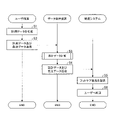
- FIG. 3 shows the processing flow of the foot care product providing system 100 when providing the foot care product 5.
- the user terminal 1 generates measurement data of the three-dimensional shape of the user's foot (step S1).
- the measurement data refers to data obtained by measuring the three-dimensional shape of the foot or data used for calculation for measurement.
- the user terminal 1 can transmit the image data of the foot taken by the camera to the data providing device 2 as measurement data.
- the data providing device 2 can analyze the image data and calculate the three-dimensional shape of the foot.
- the measurement data is not limited to photographed image data, and may be data obtained by calculating a three-dimensional shape such as the length, width, or instep height of the user terminal 1 from the image data. Data that has already been measured in and input by the user may be used.
- FIG. 4 is a diagram for explaining a method of measuring feet.
- the feet are photographed from multiple directions.
- the auxiliary tool for measurement is photographed together with the foot.
- a sheet 11 on which a grid is printed, a sticker-like marker 12 to be attached to the leg, or the like can be used.
- the three-dimensional size of the foot can be easily calculated based on the position, size, or degree of deformation of the shape of the grid or marker 12 .
- the seat 11 is arranged so as to surround not only the floor surface but also the three sides of the foot, because it facilitates three-dimensional measurement of the foot size.
- the user terminal 1 generates order data for the foot care products 5 and transmits it to the data providing device 2 together with the measurement data (step S2).
- the order data includes orderer information such as the name and address of the user who placed the order, product information data such as the type of foot care product 5 to be purchased (insole, pad or sock), color or price.
- the processing of the user terminal 1 may be performed by an application installed on the user terminal 1. According to guidance from the application, the user can perform input operations such as the photographing and orderer information. Alternatively, the user terminal 1 may access a website from which the foot care product 5 can be ordered, and follow the instructions on the website to upload photographed data, orderer information, etc. to the website. Both the application and website are provided by the data providing device 2 .
- control unit 211 receives the order data transmitted from the user terminal 1 and instructs the calculation processing unit 212 to design.
- the calculation processing unit 212 calculates the design data of the foot care product 5 based on the measurement data transmitted together with the order data in accordance with the instruction from the control unit 211 (step S3). Calculation of design data will be described later.
- control unit 211 generates order data from the order data and causes the communication unit 23 to transmit it to the manufacturing system 3 together with the calculated design data (step S4).
- the order data includes data such as product information of the foot care product 5 to be manufactured, orderer information of the user who delivers the foot care product 5, and the like.
- the reception terminal 31 when the reception terminal 31 receives the order data transmitted from the data providing device 2 , the reception terminal 31 transmits the design data transmitted together with the order data to the manufacturing device 32 .
- the manufacturing device 32 manufactures the foot care product 5 based on the design data (step S5).
- the design data specifies the type of resin.
- the manufacturing device 32 can manufacture the insole or pad by 3D printing using the designated type of resin.
- the manufacturing device 32 also arranges the sensor 6 on the foot care product 5 based on the design data. Thereby, the sensor 6 is arranged at a position based on the three-dimensional size of the user's foot.
- the reception terminal 31 executes delivery processing based on the order data (step S6). For example, in the delivery process, the reception terminal 31 prints a delivery destination list, an invoice of the delivery destination, and the like, and transmits delivery request data to the computer of the delivery company.
- FIG. 5 shows the processing of the data providing device 2 when calculating design data.
- the calculation processing unit 212 first calculates the three-dimensional size of the user's foot from the measurement data (step S31).
- the calculation processing unit 212 analyzes a plurality of image data to detect edges of the surface of the foot, and calculates the length, width, and height of the foot at a plurality of positions. Calculate in When the sheet 11 with the grid or the marker 12 is included in the photographed image, the calculation processing unit 212 detects the grid and the marker 12 in the sheet 11 . The calculation processing unit 212 can also calculate the length, width and height of the foot from the distances between the vertices of the grid, or calculate the position of the surface of the foot by measuring the distance from the floor to the marker 12. can also
- the calculation processing unit 212 prepares a database in advance of the distance from the camera to the grid or marker 12, the amount of deformation of the grid or marker 12 when changing the angle of the surface of the foot, or the amount of change in size. can also In this case, by matching the amount of deformation or the amount of change in size of the grid of the sheet 11 or of the marker 12 detected from the image data with the database, the distance from the camera to the grid or the marker 12, the surface of the foot, Tilt angles, distances between markers 12, etc. can be calculated.
- the calculation processing unit 212 may calculate the feature amount from each image data and detect the position of the feature point having the common feature amount.
- a three-dimensional model of the foot can be formed by arranging detected feature points in a three-dimensional space using feature points such as the toes, heels, and ankles of the feet as reference points. Any known calculation method can be used as long as the size of the three-dimensional shape can be calculated without being limited to the calculation method described above.
- the calculation processing unit 212 calculates the material, thickness, shape, size, etc. of the sock part, which is a fabric product among the foot care products 5, based on the calculation result of the foot size (step 32). This process is omitted when the foot care product 5 is only a resin product such as an insole or a pad.
- the calculation processing unit 212 can compare the user's foot size with the standard foot size, and determine the material, thickness, shape, size, etc. of the parts of the sock according to the difference. For example, when the width of the foot is larger than the standard size by a certain value or more, the calculation processing unit 212 divides the sock into three parts: a part that covers the sole, a part that covers the right side of the foot, and a part that covers the left side of the foot. can do.
- the sock it is better for the sock to have high elasticity, as the areas with more unevenness than the standard size are more likely to rub against the shoes and receive impact when walking.
- the elasticity of the sock can be enhanced by choosing a thick material fabric or choosing a highly cushioned knitting method such as pile knitting. Normally, the material and weaving method of all parts are the same, but if, for example, the width of the foot and the height of the instep at the big toe are larger than the standard size by more than a certain amount, the elasticity of the part covering the big toe will be increased by one level.
- the computational processing unit 212 can determine the thickness, material, or knitting of the part.
- the calculation processing unit 212 calculates the elasticity, material, thickness, shape, size, or arrangement position of the insoles, pads, sandals, etc., which are resin products among the foot care products 5, based on the calculation result of the foot size. etc. are calculated (step S33). Specifically, the calculation processing unit 212 can compare the user's foot size with a standard shoe size or a standard foot size, and determine the elasticity or the like according to the difference.
- 6A and 6B show an example of a user's foot size and standard shoe and foot sizes. 6A is a side view and FIG. 6B is a top view.
- the calculation processing unit 212 reads out the standard size shoe model K2 and the standard size foot model K3 from the storage unit 22 and arranges them in the three-dimensional virtual space. Each model K2 and K3 is generated in advance based on a statistically average size for each foot length and stored in the storage unit 22 .
- the shoe model K2 is a three-dimensional virtual model that reproduces the three-dimensional shape of the inner surface of the shoe.
- a standard size foot model (hereinafter referred to as a standard model) K3 is a three-dimensional virtual model that reproduces the three-dimensional shape of a standard foot.
- Three points P1 to P3 for supporting the foot during walking are set at the big toe, little toe and heel of the standard foot model K3. Also, an arch A connecting points P1 to P3 is set.
- the calculation processing unit 212 generates a three-dimensional model K1 that reproduces the three-dimensional shape of the surface of the user's foot from the measurement result of the user's foot size.
- the calculation processing unit 212 arranges the foot model K1 inside the shoe model K2 in the virtual space, and adjusts the position so that the end in the front-rear direction y matches the standard foot model K3.
- the calculation processing unit 212 matches the foot model K1 with the standard model K3 to determine points P1 to P3 in the foot model K1. For example, the calculation processing unit 212 projectively transforms the points P1 to P3 and the arch A set in the standard model K3 to the model K1.
- the calculation processing unit 212 determines the size and thickness of the insole 51 to be placed in the shoe model K2 so that the weight is supported at the three points P1 to P3 and the curvature of the arch A is maintained. do.
- the base insole 51 is determined to have a size and shape that is smaller than the area of the sole and larger than the area of the foot, and the thickness is determined so as to fit the toes and heels.
- the thickness is adjusted so that the upper surface of the foot model K1 is separated from the shoe model K3 by a certain distance or more in the height direction z.
- the calculation processing unit 212 adds the pads 53a and 53b to the insole 51. placement can be determined.
- the pads 53 a and 53 b may be attached to the upper surface of the insole 51 or embedded inside the insole 51 . Depending on the arrangement of the pads 53a and 53b, the insole 51 can be provided with elasticity different from thickness.
- the pad 53a is placed on the arch in order to maintain the shape of the arch A.
- the calculation processing unit 212 determines the shape and size of the pad 53a so as to fill the space between the upper surface of the insole 51 and the arch of the foot.
- Pad 53b is placed in the middle of the foot so that weight is applied to points P2 and P3.
- the calculation processing unit 212 adjusts the three-dimensional shape and size of the pad 53b so that the distance between the points P1 to P3 and the difference in curvature of the arch A between the foot model K1 and the standard model K3 are small. decide.
- the pads 53a and 53b may be pads arranged around the heel, instep, ankle, or the like. For example, if the foot has large unevenness, a pad may be arranged to fill the unevenness.
- the calculation processing unit 212 detects a recess where the size difference between the foot model K1 and the standard model K2 is greater than or equal to a threshold, and determines the three-dimensional shape and size of the pad so as to fill the recess.
- the calculation processing unit 212 calculates the elasticity and materials of the insole 51 and the pads 53a and 53b according to the difference between the user's foot model K1 and the standard model K3 or the difference between the foot model K1 and the shoe model K3. to decide.
- FIG. 7 shows an example of a table T1 that can be used to determine elasticity and material.
- Table T1 is stored in storage unit 22 .
- elasticity and material are associated with the difference from the standard model K3 or the shoe model K2 for each part of the foot.
- FIG. 7 when the foot model K1 is smaller and the difference is a negative value, it is indicated by (-).
- the difference between the foot model K1 and the standard model K3 is 10 mm or more, or the difference between the foot model K1 and the shoe model K2 (the distance from the foot to the shoe). is less than 10 mm, "soft” is associated with the elasticity, and "EVA (ethylene-vinyl acetate copolymer)" is associated with the material having this elasticity.
- the calculation processing unit 212 determines the elasticity of the insole 51 and the pads 53a and 53b and the materials to be used from the difference between the user's foot size and the standard foot size or shoe size.
- the type of resin used can be determined.
- the calculation processing unit 212 calculates the arrangement position of the sensor 6 on the foot care product 5 (step S34).
- asterisks exemplify the placement positions of the sensors 6 .
- the computation processing unit 212 computes the part where the foot is deformed due to the difference in three-dimensional size between the foot model K1 and the standard model K2.
- the calculation processing unit 212 determines the calculated site as the placement position of the sensor 6 .
- the calculation processing unit 212 determines that a deformation in which the big toe protrudes in the width direction x, that is, a so-called hallux valgus, has occurred. 6 placement positions.
- the calculation processing unit 212 can also calculate the part where the burden on the foot is predicted based on the difference between the foot model K1 and the shoe model K3, and determine the arrangement of the sensor 6 here. For example, when the instep is deformed to protrude upward, the distance in the height direction z from the instep to the shoe is short, and the foot is likely to be compressed.
- the calculation processing unit 212 compares the difference between the instep foot model K1 and the standard model K2 (the distance from the foot to the shoe) with a threshold, and if the difference is shorter than the threshold, the sensor 6 is placed on the shortest part. It can also be determined as a position.
- the calculation processing unit 212 can also determine a position that affects walking as the placement position of the sensor 6 .
- the points P1 to P3 can be determined as the placement positions of the sensors 6 in order to confirm whether the feet are supported at the points P1 to P3.
- the sensor 6 of this embodiment is a pressure sensor, but a temperature sensor, a humidity sensor, or the like may be used. Further, the sensor 6 of the present embodiment has wireless communication functions such as RFID (Radio Frequency IDentification System) and Bluetooth (registered trademark). This allows the sensor 6 to transmit the state of the foot to an external device such as the user terminal 1 at any time.
- RFID Radio Frequency IDentification System
- Bluetooth registered trademark
- the sensor 6 may be embedded inside the foot care product 5 such as the insole 51 or the pad 53a, or may be arranged on the surface of the foot care product 5.
- the calculation processing unit 212 can determine an arrangement method that places less burden on the foot according to the type of the sensor 6 and the distance from the foot to the shoe.
- FIG. 8 shows a sock 5A as an example of the foot care product 5.
- the sock 5A is a separate type sock that separately accommodates the thumb and fingers other than the thumb.
- the sock 5A consists of an insole 51 and a sock body 52. - ⁇ The sock main body 52 is integrally formed by sewing a bottom part and two left and right parts.
- the insole 51 is arranged on the bottom surface of the sock body 52 .
- the size, thickness, material, etc. of the insole 51 and the size, shape, material, etc. of each part of the main body of the sock 52 are determined based on the design data as described above.
- a plurality of sensors 6 are arranged on the sock 5A.
- the sensor 6 is also arranged at a position determined based on the three-dimensional size of the user's foot as described above. Some sensors 6 are embedded inside the insole 51 , while others are located on the outer surface or side of the sock body 52 .
- Detected data such as pressure output from the sensor 6 can be used to generate guidance data for the user's walking.
- the detection data can also be used to calculate design data when manufacturing new foot care products 5 .
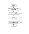
- FIG. 9 shows the flow of processing when providing guidance data in the foot care product providing system 100.
- the user terminal 1 receives detection data transmitted from the sensor 6 (step S11), it transmits the detection data to the data providing device 2 (step S12).
- the calculation processing unit 212 generates guidance data based on the transmitted detection data (step S13).
- Guidance data includes, for example, information on the walking condition of the user, information on lesions predicted in the future, advice on correct walking methods, and the like.
- the instructional data can include images, videos, etc. that describe the correct way to walk.
- FIG. 10 shows an example of a table T2 that can be used to generate coaching data.
- instruction data is associated with the foot part and the level of pressure detected by the sensor 6 at that part.
- the calculation processing unit 212 calculates from the table T2, " Acquire guidance data such as "Hallux valgus may progress", “Land on the heel and kick strongly with your fingertips”.
- the control unit 211 controls the communication unit 23 to transmit guidance data to the user terminal 1 that transmitted the detection data (step S14).
- the user terminal 1 displays the transmitted guidance data (step S15).
- the shape of the foot may have changed, so the user terminal 1 photographs the foot and generates new measurement data. Then, as shown in FIG. 3, the user terminal 1 transmits the data together with the order data to the data providing device 2. FIG. At this time, the user terminal 1 can also transmit the detection data of the sensor 6 together.
- the data providing device 2 can calculate the design data of the newly manufactured foot care product 5 based on the detection data transmitted from the user terminal 1. For example, if the pressure level on the bottom side of the big toe is higher than the threshold value according to the detection data, the calculation processing unit 212 calculates the design data based on the measurement data, and then reduces the elasticity of the insole at the position of the big toe by one level. data can be changed.
- Design data may be calculated based not only on detection data at the time of ordering, but also on past detection data or guidance data generated from the detection data. As a result, it is possible to design foot care products 5 that better fit the foot based on past walking conditions and changes in the condition of the foot.
- the user terminal 1 transmits measurement data such as a photographed image of the foot to the data providing device 2 .
- the data providing device 2 calculates design data for the foot care product 5 based on the transmitted measurement data, and transmits the design data to the manufacturing system 3 .
- the manufacturing system 3 manufactures foot care products 5 based on the design data.
- the data providing device 2 uses the calculation processing unit 212 to calculate the size and elasticity of the foot care product 5, the arrangement position of the sensor 6, and the like.
- the user terminal 1 can order and measure the foot care products 5, the user can order the foot care products 5 customized specifically for the user's feet by a simple procedure while staying at home. Even commercially available shoes can fit the feet by wearing the foot care product 5, so the variation of shoes that can be selected increases, and the degree of freedom in design increases. Among the foot care products 5, innerwear is less expensive than custom-made shoes, so the user's financial burden can be reduced.
- the detection data of the sensor 6 placed on the foot care product 5 can be transmitted from the user terminal 1 to the data providing device 2.
- the data providing device 2 generates guidance data on walking from the detection data and transmits the guidance data to the user terminal 1 . This allows the user to monitor the user's foot condition or walking condition. In addition, it is possible to appropriately determine replacement timing.
- the detection data of the sensor 6 can also be used to calculate the design data of the foot care products 5 for the second and subsequent pairs. As a result, it is possible to provide the foot care product 5 which is improved so that the shoes fit the feet more easily and the walking is easily assisted.
- the model K2 of a standard size shoe is used, but the user terminal 1 may photograph the shoe and transmit the image data to the data providing device 2 as measurement data of the shoe.
- the calculation processing unit 212 can use the measurement data of the shoe to calculate the three-dimensional shape of the inner surface of the shoe and generate the model K2 of the shoe.
- the three-dimensional size of the inner surface of the shoe can be calculated in the same manner as the three-dimensional size of the foot. Since only the edge of the outer surface of the shoe can be detected from the image data, the calculation processing unit 212 can calculate the size of the inner surface by regarding, for example, 1 cm inside from the edge as the inner surface of the shoe.
- the present invention is particularly useful for foot lesion patients who need their shoes customized, but can also be used by users without lesions.
- commercially available shoes may fit the length of the foot, the width and height may not match the foot, but according to the present invention, the foot care product 5 that can fit the foot to the shoe can be provided by a simple procedure. can be purchased.
- Guidance data can also be used to predict the occurrence of future lesions and improve walking methods.
- the calculation processing unit 212 is implemented by software processing in which the CPU 21 reads and executes programs, but it may be implemented by hardware processing such as FPGA (Field-Programmable Gate Array). Also, a recording medium recording a program to be executed by a computer may be provided.
- the recording medium is not particularly limited as long as it is readable by computers such as CPUs and microcomputers, and semiconductor memories, magnetic disks, optical disks, and the like can be used.
- Foot care product providing system 1... User terminal, 2... Data providing device, 21... CPU, 22... Storage unit, 3... Manufacturing system, 5... Foot care product, 6... sensor
Abstract
The present invention provides a foot care product that reduces a load on the feet of a user by fitting the feet to shoes. A data providing device 2 provides design data for a foot care product tailored to the three-dimensional shapes of the feet of the user. The data providing device 2 comprises: a communication unit that receives measurement data on the three-dimensional shapes of the feet of the user from a user terminal 1; and a calculation processing unit that calculates the design data for the foot care product on the basis of the measurement data. The calculation processing unit calculates, as the design data, the size and elasticity of the foot care product and locations where sensors are to be placed in the foot care product. The communication unit transmits the design data to a manufacturing system 3 for manufacturing the foot care product.
Description
本発明は、データ提供装置、フットケア製品提供方法及びフットケア製品に関する。
The present invention relates to a data providing device, a foot care product providing method, and a foot care product.
足の変形等を伴う足病変患者は、市販の靴ではフィットせず、足の負担も大きいため、専用の靴やインソールのオーダーメイドが必要であった。しかし、医師の診断や装具士による足のサイズの計測及び靴の調整等のために、病院や店舗に何度も通わなければならず、オーダーメイドは不便であった。
For patients with foot lesions accompanied by foot deformities, commercial shoes do not fit well and the burden on the feet is heavy, so custom-made special shoes and insoles were necessary. However, custom-made shoes are inconvenient because they require many visits to hospitals and shops for diagnosis by a doctor, measurement of foot size by a prosthetist, adjustment of shoes, and the like.
そこで、靴のオーダーメイドを容易に利用できるように、ユーザの足を撮影し、その撮影画像から足の寸法を計測して、靴の3D型を形成するシステムが提案されている(例えば、特許文献1参照)。
Therefore, in order to facilitate custom-made shoes, a system has been proposed in which a user's foot is photographed, the dimensions of the foot are measured from the photographed image, and a 3D model of the shoe is formed (for example, patent Reference 1).
しかし、オーダーメイドにより足の形状に合った靴を購入した場合でも、病変の進行により足の形状が変わると、靴の買い替えが必要になる。オーダーメイドの靴は市販の靴に比べて高価であるため、頻繁に買い替えると経済的な負担が大きくなる。
However, even if a custom-made shoe that matches the shape of the foot is purchased, if the shape of the foot changes due to progression of the lesion, it will be necessary to replace the shoe. Since custom-made shoes are more expensive than commercially available shoes, frequent replacement of shoes increases the financial burden.
また、オーダーメイドの靴は治療を目的としているため、市販の靴に比べて靴のデザイン性に乏しい。そのため、安価でデザインの自由度が高い市販の靴を、足の形状に合わせて履きたいという要望があった。
In addition, since custom-made shoes are intended for treatment, the design of the shoes is poor compared to commercially available shoes. For this reason, there has been a demand to wear commercially available shoes that are inexpensive and have a high degree of freedom in design in accordance with the shape of the foot.
本発明が解決しようとする課題は、靴に足をフィットさせて、ユーザの足の負担を減らすフットケア製品を提供することにある。
The problem to be solved by the present invention is to provide a foot care product that fits shoes to the feet and reduces the burden on the user's feet.
本発明は以下の態様を包含する。
[1]ユーザの足の立体形状に応じたフットケア製品の設計データを提供するデータ提供装置であって、
前記ユーザの足の立体形状の計測データをユーザ端末から受信する通信部と、
前記計測データに基づいて、前記フットケア製品の設計データを計算する計算処理部と、を備え、
前記計算処理部は、前記設計データとして、前記フットケア製品のサイズ、弾性及び前記フットケア製品におけるセンサの配置位置を計算し、
前記通信部は、前記設計データを前記フットケア製品の製造システムへ送信する
データ提供装置。 The present invention includes the following aspects.
[1] A data providing device that provides design data for a foot care product according to the three-dimensional shape of a user's foot,
a communication unit that receives measurement data of a three-dimensional shape of the foot of the user from a user terminal;
a calculation processing unit that calculates design data for the foot care product based on the measurement data;
The calculation processing unit calculates, as the design data, the size and elasticity of the foot care product and the arrangement position of the sensor in the foot care product,
The data providing device, wherein the communication unit transmits the design data to the foot care product manufacturing system.
[2]前記センサは、圧力センサである
上記[1]に記載のデータ提供装置。 [2] The data providing device according to [1], wherein the sensor is a pressure sensor.
上記[1]に記載のデータ提供装置。 [2] The data providing device according to [1], wherein the sensor is a pressure sensor.
[3]前記センサは、無線通信により検出データを前記ユーザ端末に送信し、
前記計算処理部は、前記ユーザ端末から送信される前記検出データに基づいて、前記ユーザの歩行に関する指導データを生成し、
前記通信部は、前記指導データを前記ユーザ端末に送信する
上記[1]又は[2]に記載のデータ提供装置。 [3] The sensor transmits detection data to the user terminal by wireless communication;
The calculation processing unit generates guidance data related to walking of the user based on the detection data transmitted from the user terminal,
The data providing device according to the above [1] or [2], wherein the communication unit transmits the guidance data to the user terminal.
[4]前記計算処理部は、前記検出データに基づいて、新たに製造する前記フットケア製品の前記設計データの計算を行う
上記[3]に記載のデータ提供装置。 [4] The data providing device according to [3], wherein the calculation processing unit calculates the design data of the foot care product to be newly manufactured based on the detection data.
上記[3]に記載のデータ提供装置。 [4] The data providing device according to [3], wherein the calculation processing unit calculates the design data of the foot care product to be newly manufactured based on the detection data.
[5]前記フットケア製品は、インソール、パッド、又は前記インソールが底に配置されたソックスを含み、
前記計算処理部は、前記設計データとして、前記インソール、前記パッド及び前記ソックスの素材、厚み、形状及びサイズを計算する
上記[1]~[4]のいずれかに記載のデータ提供装置。 [5] The foot care product includes an insole, a pad, or a sock with the insole disposed on the bottom,
The data providing device according to any one of [1] to [4] above, wherein the calculation processing unit calculates materials, thicknesses, shapes and sizes of the insole, the pad and the sock as the design data.
[6]前記インソール又は前記パッドは、樹脂を用いて3Dプリントにより製造され、
前記計算処理部は、前記樹脂の種類を前記設計データとして計算する
上記[5]に記載のデータ提供装置。 [6] The insole or the pad is manufactured by 3D printing using resin,
The data providing device according to [5], wherein the calculation processing unit calculates the type of the resin as the design data.
前記計算処理部は、前記樹脂の種類を前記設計データとして計算する
上記[5]に記載のデータ提供装置。 [6] The insole or the pad is manufactured by 3D printing using resin,
The data providing device according to [5], wherein the calculation processing unit calculates the type of the resin as the design data.
[7]ユーザの足の立体形状に応じたフットケア製品を提供する方法であって、
ユーザ端末が前記ユーザの足の立体形状の計測データを生成し、データ提供装置へ送信するステップと、
前記データ提供装置が、前記計測データに基づいて、前記フットケア製品のサイズ、弾性及び前記フットケア製品におけるセンサの配置位置を前記フットケア製品の設計データとして計算し、前記フットケア製品の製造システムへ送信するステップと、
前記製造システムにおいて、前記設計データに基づいて前記フットケア製品を製造するステップと、
を含むフットケア製品提供方法。 [7] A method of providing a foot care product according to the three-dimensional shape of a user's foot,
a step in which the user terminal generates measurement data of the three-dimensional shape of the user's foot and transmits the measurement data to a data providing device;
The data providing device calculates the size and elasticity of the foot care product and the arrangement position of the sensor in the foot care product as design data of the foot care product based on the measurement data, and the foot care product manufacturing system sending to
manufacturing the foot care product based on the design data in the manufacturing system;
foot care product delivery methods, including;
[8]ユーザが着用するフットケア製品であって、
靴の底に配置されるインソール、前記靴の内部に配置されるパッド、又は前記インソールが底に配置されたソックスを含み、
前記インソール、前記パッド又は前記ソックスの内部又は表面に配置されるセンサを備え、
前記センサは、前記ユーザの足の立体的なサイズに基づく位置に配置される
フットケア製品。 [8] A foot care product worn by a user, comprising:
an insole placed on the bottom of a shoe, a pad placed inside the shoe, or a sock with the insole placed on the bottom;
a sensor disposed inside or on the surface of the insole, pad or sock;
The foot care product, wherein the sensor is placed at a position based on the three-dimensional size of the user's foot.
本発明によれば、靴に足をフィットさせて、ユーザの足の負担を減らすフットケア製品を提供することができる。
According to the present invention, it is possible to provide a foot care product that reduces the burden on the user's feet by fitting the shoes to the feet.
以下、本発明の一実施形態について詳細に説明する。以下の実施形態は、本発明を説明するための例示であり、本発明はこれに限定されるものではない。
An embodiment of the present invention will be described in detail below. The following embodiments are exemplifications for explaining the present invention, and the present invention is not limited thereto.
(フットケア製品提供システム)
図1は、フットケア製品提供システム100の構成を示す。
フットケア製品提供システム100では、ユーザ端末1、データ提供装置2及び製造システム3がネットワークNを介して接続されている。ネットワークNとしては、インターネットや電話回線等の公知のネットワークを使用できる。 (Foot care product provision system)
FIG. 1 shows the configuration of a foot careproduct providing system 100. As shown in FIG.
In the foot careproduct providing system 100, a user terminal 1, a data providing device 2 and a manufacturing system 3 are connected via a network N. As the network N, a known network such as the Internet or a telephone line can be used.
図1は、フットケア製品提供システム100の構成を示す。
フットケア製品提供システム100では、ユーザ端末1、データ提供装置2及び製造システム3がネットワークNを介して接続されている。ネットワークNとしては、インターネットや電話回線等の公知のネットワークを使用できる。 (Foot care product provision system)
FIG. 1 shows the configuration of a foot care
In the foot care
フットケア製品提供システム100では、ユーザ端末1によりフットケア製品5の発注を受け付けて、データ提供装置2によりフットケア製品5の設計データを計算する。この設計データに基づいて、製造システム3においてフットケア製品5を製造し、ユーザに提供する。ユーザは、例えば足の変形を伴う足病変患者である。
In the foot care product providing system 100, the user terminal 1 receives an order for the foot care product 5, and the data providing device 2 calculates design data for the foot care product 5. Based on this design data, the manufacturing system 3 manufactures the foot care product 5 and provides it to the user. The user is, for example, a foot patient with foot deformity.
フットケア製品5は、ユーザの足の負担を減らすための製品である。フットケア製品5は、靴の中で着用されるインナーだけでなく、サンダル等の靴型の製品であってもよい。インナーとしては、例えば靴の中に配置されるインソール、パッド、又はユーザが靴の中で着用するソックス等が挙げられる。ソックスは、通常、その底にインソールが配置される。
The foot care product 5 is a product for reducing the burden on the user's feet. The foot care product 5 may be not only innerwear worn inside shoes, but also shoe last products such as sandals. Examples of innerwear include insoles and pads placed inside shoes, socks worn by users inside shoes, and the like. Socks usually have an insole placed on their bottom.
足病変患者にとっては市販の靴は足の形状に合わず、着用が難しいが、フットケア製品5の着用によってこのような市販の靴にも足をフィットさせることができる。オーダーメイドの靴を発注する必要がなく、多種多様な市販の靴の中から好みの靴を選択できるため、靴のデザインの選択の自由度が向上する。また、靴よりはフットケア製品5の方が低コストであるため、ユーザの経済的な負担を減らすことができる。
For patients with foot lesions, commercially available shoes do not fit the shape of their feet and are difficult to wear, but by wearing foot care product 5, these commercially available shoes can also fit their feet. There is no need to order custom-made shoes, and users can select their favorite shoes from a wide variety of shoes on the market, thereby improving the degree of freedom in selecting shoe designs. Moreover, since the cost of the foot care product 5 is lower than that of shoes, the financial burden on the user can be reduced.
<ユーザ端末>
ユーザ端末1は、カメラ付きの通信端末等のように画像データを送信可能な端末であれば特に限定されない。ユーザ端末1としては、例えばユーザが使用するスマートフォン、タブレット型、ノート型又はデスクトップ型のPC(Personal Computer)等を使用できる。ユーザ端末1は、ユーザの操作入力に応じて、フットケア製品5の発注データをデータ提供装置2に送信する。また、ユーザ端末1は、ユーザの足を撮影した画像データ等を計測データとしてデータ提供装置2に送信する。 <User terminal>
Theuser terminal 1 is not particularly limited as long as it is a terminal capable of transmitting image data, such as a communication terminal with a camera. As the user terminal 1, for example, a smart phone, a tablet type, a notebook type or a desktop type PC (Personal Computer) used by the user can be used. The user terminal 1 transmits order data for the foot care product 5 to the data providing device 2 in accordance with the user's operation input. In addition, the user terminal 1 transmits image data of the user's foot or the like as measurement data to the data providing device 2 .
ユーザ端末1は、カメラ付きの通信端末等のように画像データを送信可能な端末であれば特に限定されない。ユーザ端末1としては、例えばユーザが使用するスマートフォン、タブレット型、ノート型又はデスクトップ型のPC(Personal Computer)等を使用できる。ユーザ端末1は、ユーザの操作入力に応じて、フットケア製品5の発注データをデータ提供装置2に送信する。また、ユーザ端末1は、ユーザの足を撮影した画像データ等を計測データとしてデータ提供装置2に送信する。 <User terminal>
The
<データ提供装置>
データ提供装置2は、ユーザ端末1からフットケア製品5の発注データを受信すると、ユーザ端末1から受信した計測データに基づき、ユーザの足の立体形状に応じたフットケア製品5の設計データを生成する。データ提供装置2は、設計データをフットケア製品5の受注データとともに製造システム3に送信する。また、データ提供装置2は、ユーザの歩行に関する指導データをユーザ端末1に送信することができる。 <Data providing device>
When receiving order data forfoot care products 5 from the user terminal 1, the data providing device 2 generates design data for the foot care products 5 according to the three-dimensional shape of the user's feet based on the measurement data received from the user terminal 1. do. The data providing device 2 transmits the design data to the manufacturing system 3 together with order data for the foot care products 5 . In addition, the data providing device 2 can transmit guidance data on walking of the user to the user terminal 1 .
データ提供装置2は、ユーザ端末1からフットケア製品5の発注データを受信すると、ユーザ端末1から受信した計測データに基づき、ユーザの足の立体形状に応じたフットケア製品5の設計データを生成する。データ提供装置2は、設計データをフットケア製品5の受注データとともに製造システム3に送信する。また、データ提供装置2は、ユーザの歩行に関する指導データをユーザ端末1に送信することができる。 <Data providing device>
When receiving order data for
図2は、データ提供装置2の構成例を示す。
データ提供装置2は、CPU(Central Processing Unit)21、記憶部22、通信部23、表示部24及び操作部25等を備える。 FIG. 2 shows a configuration example of thedata providing device 2. As shown in FIG.
Thedata providing device 2 includes a CPU (Central Processing Unit) 21, a storage section 22, a communication section 23, a display section 24, an operation section 25, and the like.
データ提供装置2は、CPU(Central Processing Unit)21、記憶部22、通信部23、表示部24及び操作部25等を備える。 FIG. 2 shows a configuration example of the
The
CPU21は、記憶部22からプログラムを読み出して実行することにより、制御部211及び計算処理部212として機能する。
The CPU 21 functions as a control section 211 and a calculation processing section 212 by reading and executing programs from the storage section 22 .
制御部211は、データ提供装置2の各部を制御する。例えば、通信部23を制御してユーザ端末1又は製造システム3との間でデータの受信又は送信を行わせる。計算処理部212は、設計データ及び指導データを生成する。
The control unit 211 controls each unit of the data providing device 2 . For example, it controls the communication unit 23 to receive or transmit data with the user terminal 1 or the manufacturing system 3 . The calculation processing unit 212 generates design data and guidance data.
記憶部22は、CPU21が読み取り可能なプログラム、及びプログラムの実行に用いられるテーブル等を記憶する。記憶部22としては、例えばハードディスク等の記録媒体を用いることができる。
The storage unit 22 stores programs readable by the CPU 21, tables used for executing the programs, and the like. As the storage unit 22, a recording medium such as a hard disk can be used, for example.
通信部23は、ネットワークNを介してユーザ端末1等の外部のコンピュータと通信するインターフェイスである。
The communication unit 23 is an interface that communicates with an external computer such as the user terminal 1 via the network N.
表示部24は、ディスプレイ等である。表示部24は、CPU21の指示にしたがって、操作画面やCPU21の処理結果等を表示する。
The display unit 24 is a display or the like. The display unit 24 displays an operation screen, processing results of the CPU 21, and the like according to instructions from the CPU 21. FIG.
操作部25は、キーボード、又はマウス等である。操作部25は、ユーザの操作を受け付けて、その操作内容をCPU21に出力する。
The operation unit 25 is a keyboard, mouse, or the like. The operation unit 25 receives user's operations and outputs the operation contents to the CPU 21 .
<製造システム>
製造システム3は、受付端末31、フットケア製品5の製造装置32等を備える。製造装置32としては、例えば樹脂を成形する3Dプリンタ、生地の裁断装置又は縫製装置等が挙げられる。 <Manufacturing system>
Themanufacturing system 3 includes a reception terminal 31, a manufacturing device 32 for the foot care product 5, and the like. Examples of the manufacturing device 32 include a 3D printer that molds resin, a fabric cutting device, a sewing device, and the like.
製造システム3は、受付端末31、フットケア製品5の製造装置32等を備える。製造装置32としては、例えば樹脂を成形する3Dプリンタ、生地の裁断装置又は縫製装置等が挙げられる。 <Manufacturing system>
The
受付端末31は、データ提供装置2からフットケア製品5の受注データ及びフットケア製品5の設計データを受信すると、製造装置32に設計データを送信する。製造装置32は、設計データに基づいてフットケア製品5又はそのパーツを形成する。各パーツを組み立てることによりフットケア製品5が製造されると、受付端末31はフットケア製品5の配送処理を行う。
Upon receiving the order data for the foot care products 5 and the design data for the foot care products 5 from the data providing device 2 , the reception terminal 31 transmits the design data to the manufacturing device 32 . The manufacturing device 32 forms the foot care product 5 or parts thereof based on the design data. After the foot care product 5 is manufactured by assembling the parts, the reception terminal 31 performs delivery processing of the foot care product 5 .
(フットケア製品提供処理)
図3は、フットケア製品5を提供するときのフットケア製品提供システム100の処理の流れを示す。
フットケア製品提供システム100では、まずユーザ端末1がユーザの足の立体形状の計測データを生成する(ステップS1)。計測データとは、足の立体形状が計測されたデータ又は計測のための計算に用いられるデータをいう。 (Providing foot care products)
FIG. 3 shows the processing flow of the foot careproduct providing system 100 when providing the foot care product 5. As shown in FIG.
In the foot careproduct providing system 100, first, the user terminal 1 generates measurement data of the three-dimensional shape of the user's foot (step S1). The measurement data refers to data obtained by measuring the three-dimensional shape of the foot or data used for calculation for measurement.
図3は、フットケア製品5を提供するときのフットケア製品提供システム100の処理の流れを示す。
フットケア製品提供システム100では、まずユーザ端末1がユーザの足の立体形状の計測データを生成する(ステップS1)。計測データとは、足の立体形状が計測されたデータ又は計測のための計算に用いられるデータをいう。 (Providing foot care products)
FIG. 3 shows the processing flow of the foot care
In the foot care
ユーザ端末1は、カメラにより撮影された足の画像データを計測データとしてデータ提供装置2に送信することができる。データ提供装置2では、この画像データを解析して足の立体形状を計算できる。計測データは、撮影された画像データに限らず、画像データからユーザ端末1において足の長さ、幅、又は甲の高さ等の立体形状が計算されたデータであってもよいし、病院等においてすでに計測済みのデータであってユーザにより入力されたデータであってもよい。
The user terminal 1 can transmit the image data of the foot taken by the camera to the data providing device 2 as measurement data. The data providing device 2 can analyze the image data and calculate the three-dimensional shape of the foot. The measurement data is not limited to photographed image data, and may be data obtained by calculating a three-dimensional shape such as the length, width, or instep height of the user terminal 1 from the image data. Data that has already been measured in and input by the user may be used.
図4は、足の計測方法を説明する図である。
足は複数の方向から撮影される。足の撮影時には、足とともに計測の補助ツールが撮影されることが好ましい。補助ツールとしては、格子が印刷されたシート11や、足に貼り付けられるシール状のマーカ12等が使用できる。格子やマーカ12の位置、サイズ又は形状の変形度合い等によって、足の立体的なサイズの計算が容易となる。シート11は床面だけでなく、足の三方を囲むように配置されると、立体的な足のサイズ計測が容易となり、好ましい。 FIG. 4 is a diagram for explaining a method of measuring feet.
The feet are photographed from multiple directions. When photographing the foot, it is preferable that the auxiliary tool for measurement is photographed together with the foot. As auxiliary tools, asheet 11 on which a grid is printed, a sticker-like marker 12 to be attached to the leg, or the like can be used. The three-dimensional size of the foot can be easily calculated based on the position, size, or degree of deformation of the shape of the grid or marker 12 . It is preferable that the seat 11 is arranged so as to surround not only the floor surface but also the three sides of the foot, because it facilitates three-dimensional measurement of the foot size.
足は複数の方向から撮影される。足の撮影時には、足とともに計測の補助ツールが撮影されることが好ましい。補助ツールとしては、格子が印刷されたシート11や、足に貼り付けられるシール状のマーカ12等が使用できる。格子やマーカ12の位置、サイズ又は形状の変形度合い等によって、足の立体的なサイズの計算が容易となる。シート11は床面だけでなく、足の三方を囲むように配置されると、立体的な足のサイズ計測が容易となり、好ましい。 FIG. 4 is a diagram for explaining a method of measuring feet.
The feet are photographed from multiple directions. When photographing the foot, it is preferable that the auxiliary tool for measurement is photographed together with the foot. As auxiliary tools, a
ユーザ端末1は、フットケア製品5の発注データを生成し、計測データとともにデータ提供装置2に送信する(ステップS2)。発注データは、注文したユーザの氏名、住所等の発注者情報、購入するフットケア製品5の種類(インソール、パッド又はソックス)、色又は価格等の商品情報のデータを含む。
The user terminal 1 generates order data for the foot care products 5 and transmits it to the data providing device 2 together with the measurement data (step S2). The order data includes orderer information such as the name and address of the user who placed the order, product information data such as the type of foot care product 5 to be purchased (insole, pad or sock), color or price.
上記ユーザ端末1の処理は、ユーザ端末1にインストールされたアプリによって行われてもよい。アプリによる案内に従って、ユーザは上記撮影や発注者情報等の入力操作を行うことができる。あるいは、ユーザ端末1がフットケア製品5を注文できるウェブサイトにアクセスし、ウェブサイトの案内に従いながら撮影された撮影データや発注者情報等をウェブサイト上にアップロードしてもよい。アプリ及びウェブサイトは、いずれもデータ提供装置2によって提供される。
The processing of the user terminal 1 may be performed by an application installed on the user terminal 1. According to guidance from the application, the user can perform input operations such as the photographing and orderer information. Alternatively, the user terminal 1 may access a website from which the foot care product 5 can be ordered, and follow the instructions on the website to upload photographed data, orderer information, etc. to the website. Both the application and website are provided by the data providing device 2 .
データ提供装置2では、ユーザ端末1から送信された発注データを制御部211が受け付け、計算処理部212に設計を指示する。計算処理部212は、制御部211からの指示に応じて、発注データとともに送信された計測データに基づき、フットケア製品5の設計データを計算する(ステップS3)。設計データの計算については後述する。
In the data providing device 2, the control unit 211 receives the order data transmitted from the user terminal 1 and instructs the calculation processing unit 212 to design. The calculation processing unit 212 calculates the design data of the foot care product 5 based on the measurement data transmitted together with the order data in accordance with the instruction from the control unit 211 (step S3). Calculation of design data will be described later.
さらに制御部211は、発注データから受注データを生成し、計算された設計データとともに、通信部23によって製造システム3へ送信させる(ステップS4)。受注データは、製造するフットケア製品5の商品情報、フットケア製品5を配送するユーザの発注者情報等のデータを含む。
Furthermore, the control unit 211 generates order data from the order data and causes the communication unit 23 to transmit it to the manufacturing system 3 together with the calculated design data (step S4). The order data includes data such as product information of the foot care product 5 to be manufactured, orderer information of the user who delivers the foot care product 5, and the like.
製造システム3では、データ提供装置2から送信された受注データを受付端末31が受け付けると、受付端末31は、受注データとともに送信された設計データを製造装置32に送信する。製造装置32では、設計データに基づいてフットケア製品5を製造する(ステップS5)。
In the manufacturing system 3 , when the reception terminal 31 receives the order data transmitted from the data providing device 2 , the reception terminal 31 transmits the design data transmitted together with the order data to the manufacturing device 32 . The manufacturing device 32 manufactures the foot care product 5 based on the design data (step S5).
フットケア製品5がインソール又はパッドである場合、その設計データにより樹脂の種類が指定されている。製造装置32は、指定された種類の樹脂を用いて3Dプリントによりインソール又はパッドを製造することができる。また製造装置32は、設計データに基づいてフットケア製品5にセンサ6を配置する。これにより、センサ6はユーザの足の立体的なサイズに基づく位置に配置される。
When the foot care product 5 is an insole or pad, the design data specifies the type of resin. The manufacturing device 32 can manufacture the insole or pad by 3D printing using the designated type of resin. The manufacturing device 32 also arranges the sensor 6 on the foot care product 5 based on the design data. Thereby, the sensor 6 is arranged at a position based on the three-dimensional size of the user's foot.
受付端末31では、受注データに基づいて配送処理を実行する(ステップS6)。例えば、受付端末31は、配送処理において、配送先リスト、配送先の送り状等を印刷し、配送業者のコンピュータへ配送依頼のデータを送信する。
The reception terminal 31 executes delivery processing based on the order data (step S6). For example, in the delivery process, the reception terminal 31 prints a delivery destination list, an invoice of the delivery destination, and the like, and transmits delivery request data to the computer of the delivery company.
図5は、設計データを計算するときのデータ提供装置2の処理を示す。
データ提供装置2では、まず計算処理部212が計測データからユーザの足の立体的なサイズを計算する(ステップS31)。 FIG. 5 shows the processing of thedata providing device 2 when calculating design data.
In thedata providing device 2, the calculation processing unit 212 first calculates the three-dimensional size of the user's foot from the measurement data (step S31).
データ提供装置2では、まず計算処理部212が計測データからユーザの足の立体的なサイズを計算する(ステップS31)。 FIG. 5 shows the processing of the
In the
例えば、計測データが足を撮影した画像データである場合、計算処理部212は複数の画像データを解析して足の表面のエッジを検出し、足の長さ、幅及び高さを複数の位置において計算する。撮影画像中に格子付きのシート11又はマーカ12が含まれる場合、計算処理部212はシート11中の格子及びマーカ12を検出する。計算処理部212は、格子の頂点間の距離によって足の長さ、幅及び高さを計算することもできるし、床面からマーカ12までの距離の計測により足の表面の位置を計算することもできる。
For example, if the measurement data is image data obtained by photographing a foot, the calculation processing unit 212 analyzes a plurality of image data to detect edges of the surface of the foot, and calculates the length, width, and height of the foot at a plurality of positions. Calculate in When the sheet 11 with the grid or the marker 12 is included in the photographed image, the calculation processing unit 212 detects the grid and the marker 12 in the sheet 11 . The calculation processing unit 212 can also calculate the length, width and height of the foot from the distances between the vertices of the grid, or calculate the position of the surface of the foot by measuring the distance from the floor to the marker 12. can also
計算処理部212は、あらかじめカメラから格子又はマーカ12までの距離や、足の表面の角度等を変えたときの格子又はマーカ12の形状の変形量又はサイズの変化量などをデータベース化しておくこともできる。この場合、画像データから検出されたシート11の格子の又はマーカ12の形状の変形量又はサイズの変化量を、データベースとマッチングすることにより、カメラから格子又はマーカ12までの距離、足の表面の傾斜角度、マーカ12間の距離等を計算することができる。
The calculation processing unit 212 prepares a database in advance of the distance from the camera to the grid or marker 12, the amount of deformation of the grid or marker 12 when changing the angle of the surface of the foot, or the amount of change in size. can also In this case, by matching the amount of deformation or the amount of change in size of the grid of the sheet 11 or of the marker 12 detected from the image data with the database, the distance from the camera to the grid or the marker 12, the surface of the foot, Tilt angles, distances between markers 12, etc. can be calculated.
また、計算処理部212は、各画像データから特徴量を計算し、共通の特徴量を有する特徴点の位置を検出してもよい。例えば足の指先、かかと、くるぶし等の特徴点を基準点として3次元空間上に検出された各特徴点を配置することにより、足の3次元モデルを形成することができる。
なお、立体形状のサイズを計算できるのであれば、上述した計算方法に限定されず、公知の計算方法を用いることができる。 Further, thecalculation processing unit 212 may calculate the feature amount from each image data and detect the position of the feature point having the common feature amount. For example, a three-dimensional model of the foot can be formed by arranging detected feature points in a three-dimensional space using feature points such as the toes, heels, and ankles of the feet as reference points.
Any known calculation method can be used as long as the size of the three-dimensional shape can be calculated without being limited to the calculation method described above.
なお、立体形状のサイズを計算できるのであれば、上述した計算方法に限定されず、公知の計算方法を用いることができる。 Further, the
Any known calculation method can be used as long as the size of the three-dimensional shape can be calculated without being limited to the calculation method described above.
次に、計算処理部212は、足のサイズの計算結果に基づいて、フットケア製品5のうち、生地製品であるソックスのパーツの素材、厚み、形状及びサイズ等を計算する(ステップ32)。フットケア製品5がインソール又はパッド等の樹脂製品のみの場合はこの処理は省略される。
Next, the calculation processing unit 212 calculates the material, thickness, shape, size, etc. of the sock part, which is a fabric product among the foot care products 5, based on the calculation result of the foot size (step 32). This process is omitted when the foot care product 5 is only a resin product such as an insole or a pad.
計算処理部212は、ユーザの足のサイズを足の標準サイズと比較して、その差に応じてソックスのパーツの素材、厚み、形状及びサイズ等を決定することができる。例えば、足幅が標準サイズと比べて一定値以上大きい場合、計算処理部212は、ソックスを、足底を覆うパーツ、足の右側を覆うパーツ及び左側を覆うパーツの3つに分けた形状とすることができる。
The calculation processing unit 212 can compare the user's foot size with the standard foot size, and determine the material, thickness, shape, size, etc. of the parts of the sock according to the difference. For example, when the width of the foot is larger than the standard size by a certain value or more, the calculation processing unit 212 divides the sock into three parts: a part that covers the sole, a part that covers the right side of the foot, and a part that covers the left side of the foot. can do.
標準サイズと比べて凹凸が大きい部分は、靴との擦れや歩行時の衝撃が加わりやすいため、ソックスの弾性が高い方がよい。ソックスの弾性は、厚い素材の生地を選択するか、又はパイル編みのようなクッション性の高い編み方を選択することにより高めることができる。通常はすべてのパーツの素材及び編み方は一定だが、例えば母趾における足の幅及び甲の高さが標準サイズより一定値以上大きい場合、母趾を覆うパーツの弾性が1段階高くなるように、計算処理部212はパーツの厚み、素材又は編み方を決定することができる。
It is better for the sock to have high elasticity, as the areas with more unevenness than the standard size are more likely to rub against the shoes and receive impact when walking. The elasticity of the sock can be enhanced by choosing a thick material fabric or choosing a highly cushioned knitting method such as pile knitting. Normally, the material and weaving method of all parts are the same, but if, for example, the width of the foot and the height of the instep at the big toe are larger than the standard size by more than a certain amount, the elasticity of the part covering the big toe will be increased by one level. , the computational processing unit 212 can determine the thickness, material, or knitting of the part.
また、計算処理部212は、足のサイズの計算結果に基づいて、フットケア製品5のうち、樹脂製品であるインソール、パッド又はサンダル等の弾性、素材、厚み、形状、サイズ又はパッドの配置位置等を計算する(ステップS33)。具体的には、計算処理部212は、ユーザの足のサイズを靴の標準サイズ又は足の標準サイズと比較し、その差に応じて上記弾性等を決定することができる。
Further, the calculation processing unit 212 calculates the elasticity, material, thickness, shape, size, or arrangement position of the insoles, pads, sandals, etc., which are resin products among the foot care products 5, based on the calculation result of the foot size. etc. are calculated (step S33). Specifically, the calculation processing unit 212 can compare the user's foot size with a standard shoe size or a standard foot size, and determine the elasticity or the like according to the difference.
図6A及び図6Bは、ユーザの足のサイズと靴及び足の標準サイズの一例を示す。図6Aは側面図であり、図6Bは上面図である。
計算処理部212は、記憶部22から標準サイズの靴のモデルK2と標準サイズの足のモデルK3とを読み出して、3次元の仮想空間上に配置する。各モデルK2及びK3は、足長ごとに統計上平均的なサイズを基にしてあらかじめ生成され、記憶部22に保存されている。 6A and 6B show an example of a user's foot size and standard shoe and foot sizes. 6A is a side view and FIG. 6B is a top view.
Thecalculation processing unit 212 reads out the standard size shoe model K2 and the standard size foot model K3 from the storage unit 22 and arranges them in the three-dimensional virtual space. Each model K2 and K3 is generated in advance based on a statistically average size for each foot length and stored in the storage unit 22 .
計算処理部212は、記憶部22から標準サイズの靴のモデルK2と標準サイズの足のモデルK3とを読み出して、3次元の仮想空間上に配置する。各モデルK2及びK3は、足長ごとに統計上平均的なサイズを基にしてあらかじめ生成され、記憶部22に保存されている。 6A and 6B show an example of a user's foot size and standard shoe and foot sizes. 6A is a side view and FIG. 6B is a top view.
The
靴のモデルK2は、靴の内面の立体形状が再現された3次元の仮想モデルである。標準サイズの足のモデル(以下、標準モデルという)K3は、標準的な足の立体形状が再現された3次元の仮想モデルである。足の標準モデルK3の母趾、小趾及びかかとの部位には、歩行時に足を支持する3つのポイントP1~P3が設定されている。また、ポイントP1~P3間を結ぶアーチAが設定されている。
The shoe model K2 is a three-dimensional virtual model that reproduces the three-dimensional shape of the inner surface of the shoe. A standard size foot model (hereinafter referred to as a standard model) K3 is a three-dimensional virtual model that reproduces the three-dimensional shape of a standard foot. Three points P1 to P3 for supporting the foot during walking are set at the big toe, little toe and heel of the standard foot model K3. Also, an arch A connecting points P1 to P3 is set.
次いで、計算処理部212は、ユーザの足のサイズの計測結果からユーザの足の表面の立体形状を再現した3次元のモデルK1を生成する。計算処理部212は、上記仮想空間上の靴のモデルK2の内部に足のモデルK1を配置し、前後方向yの端部が足の標準モデルK3と一致するように位置を調整する。
Next, the calculation processing unit 212 generates a three-dimensional model K1 that reproduces the three-dimensional shape of the surface of the user's foot from the measurement result of the user's foot size. The calculation processing unit 212 arranges the foot model K1 inside the shoe model K2 in the virtual space, and adjusts the position so that the end in the front-rear direction y matches the standard foot model K3.
計算処理部212は、足のモデルK1を標準モデルK3とマッチングして、足のモデルK1におけるポイントP1~P3を決定する。例えば、計算処理部212は、標準モデルK3に設定されたポイントP1~P3及びアーチAを、モデルK1に射影変換する。
The calculation processing unit 212 matches the foot model K1 with the standard model K3 to determine points P1 to P3 in the foot model K1. For example, the calculation processing unit 212 projectively transforms the points P1 to P3 and the arch A set in the standard model K3 to the model K1.
計算処理部212は、3つのポイントP1~P3において体重が支持されるように、またアーチAの湾曲度が保持されるように、靴のモデルK2内に配置するインソール51のサイズ及び厚みを決定する。例えば、ベースとなるインソール51は、靴底の領域より小さく、足の領域より大きいサイズ及び形状に決定され、足の指及びかかとにフィットするように厚みが決定される。また、厚みは、高さ方向zにおいて足のモデルK1の上面が靴のモデルK3と一定距離以上離れるように調整される。
The calculation processing unit 212 determines the size and thickness of the insole 51 to be placed in the shoe model K2 so that the weight is supported at the three points P1 to P3 and the curvature of the arch A is maintained. do. For example, the base insole 51 is determined to have a size and shape that is smaller than the area of the sole and larger than the area of the foot, and the thickness is determined so as to fit the toes and heels. In addition, the thickness is adjusted so that the upper surface of the foot model K1 is separated from the shoe model K3 by a certain distance or more in the height direction z.
足のモデルK1と標準モデルK2との間で、ポイントP1~P3間の距離の比及びアーチAの湾曲度の差が閾値以上となる場合、計算処理部212は、インソール51にパッド53a及び53bの配置を決定することができる。パッド53a及び53bは、インソール51の上面に貼り付けられてもよいし、インソール51の内部に埋め込まれてもよい。パッド53a及び53bの配置によって、インソール51に厚みと異なる弾性を付与することができる。
If the ratio of the distances between the points P1 to P3 and the difference in curvature of the arch A between the foot model K1 and the standard model K2 are equal to or greater than the threshold, the calculation processing unit 212 adds the pads 53a and 53b to the insole 51. placement can be determined. The pads 53 a and 53 b may be attached to the upper surface of the insole 51 or embedded inside the insole 51 . Depending on the arrangement of the pads 53a and 53b, the insole 51 can be provided with elasticity different from thickness.
パッド53aは、アーチAの形状を保持するため、土踏まずに配置される。計算処理部212は、インソール51の上面から足の土踏まずまでの間を埋めるように、パッド53aの形状とサイズを決定する。パッド53bは、ポイントP2及びP3に体重が加わるように足の中央部に配置される。計算処理部212は、足のモデルK1と標準モデルK3との間で、ポイントP1~P3間の距離及びアーチAの湾曲度の差が小さくなるように、パッド53bの立体的な形状及びサイズを決定する。
The pad 53a is placed on the arch in order to maintain the shape of the arch A. The calculation processing unit 212 determines the shape and size of the pad 53a so as to fill the space between the upper surface of the insole 51 and the arch of the foot. Pad 53b is placed in the middle of the foot so that weight is applied to points P2 and P3. The calculation processing unit 212 adjusts the three-dimensional shape and size of the pad 53b so that the distance between the points P1 to P3 and the difference in curvature of the arch A between the foot model K1 and the standard model K3 are small. decide.
パッド53a及び53bは、インソール51ではなく、かかとや甲、足首の周囲等に配置されるパッドであってもよい。例えば、足に大きな凹凸がある場合、その凹部を埋めるパッドが配置されてもよい。計算処理部212は、足のモデルK1と標準モデルK2とのサイズの差が閾値以上に大きい凹部を検出し、当該凹部を埋めるようにパッドの立体的な形状及びサイズを決定する。
Instead of the insole 51, the pads 53a and 53b may be pads arranged around the heel, instep, ankle, or the like. For example, if the foot has large unevenness, a pad may be arranged to fill the unevenness. The calculation processing unit 212 detects a recess where the size difference between the foot model K1 and the standard model K2 is greater than or equal to a threshold, and determines the three-dimensional shape and size of the pad so as to fill the recess.
次に、計算処理部212は、ユーザの足のモデルK1と標準モデルK3との差又は足のモデルK1と靴のモデルK3との差に応じて、インソール51、パッド53a及び53bの弾性及び素材を決定する。
Next, the calculation processing unit 212 calculates the elasticity and materials of the insole 51 and the pads 53a and 53b according to the difference between the user's foot model K1 and the standard model K3 or the difference between the foot model K1 and the shoe model K3. to decide.
図7は、弾性及び素材の決定に使用できるテーブルT1の一例を示す。テーブルT1は、記憶部22に保存されている。
テーブルT1は、足の部位ごとに、標準モデルK3との差又は靴のモデルK2との差に対して、弾性及び素材が関連付けられている。図7において足のモデルK1の方が小さく、その差が負の値になる場合は(-)と表している。 FIG. 7 shows an example of a table T1 that can be used to determine elasticity and material. Table T1 is stored instorage unit 22 .
In the table T1, elasticity and material are associated with the difference from the standard model K3 or the shoe model K2 for each part of the foot. In FIG. 7, when the foot model K1 is smaller and the difference is a negative value, it is indicated by (-).
テーブルT1は、足の部位ごとに、標準モデルK3との差又は靴のモデルK2との差に対して、弾性及び素材が関連付けられている。図7において足のモデルK1の方が小さく、その差が負の値になる場合は(-)と表している。 FIG. 7 shows an example of a table T1 that can be used to determine elasticity and material. Table T1 is stored in
In the table T1, elasticity and material are associated with the difference from the standard model K3 or the shoe model K2 for each part of the foot. In FIG. 7, when the foot model K1 is smaller and the difference is a negative value, it is indicated by (-).
例えば、母趾においてユーザの足が標準サイズと比べて幅方向xに長い場合、又は足から靴まで短い距離である場合、母趾が靴に当たりやすい。歩行時に足の擦れを減らすため、テーブルT1では、足のモデルK1と標準モデルK3との差が10mm以上か、又は足のモデルK1と靴のモデルK2との差(足から靴までの距離)が10mm未満の場合の弾性として“柔らかい“、この弾性を有する素材として“EVA(エチレン酢酸ビニル共重合体)”が関連付けられている。
For example, if the user's foot is longer than the standard size in the width direction x at the big toe, or if the distance from the foot to the shoe is short, the big toe is likely to hit the shoe. In order to reduce rubbing of the foot during walking, in Table T1, the difference between the foot model K1 and the standard model K3 is 10 mm or more, or the difference between the foot model K1 and the shoe model K2 (the distance from the foot to the shoe). is less than 10 mm, "soft" is associated with the elasticity, and "EVA (ethylene-vinyl acetate copolymer)" is associated with the material having this elasticity.
このようにテーブルT1に基づいて、計算処理部212は、ユーザの足のサイズと、足の標準サイズ又は靴のサイズとの差から、インソール51、パッド53a及び53bの弾性とその素材として使用される樹脂の種類を決定することができる。
In this way, based on the table T1, the calculation processing unit 212 determines the elasticity of the insole 51 and the pads 53a and 53b and the materials to be used from the difference between the user's foot size and the standard foot size or shoe size. The type of resin used can be determined.
次に、計算処理部212は、フットケア製品5におけるセンサ6の配置位置を計算する(ステップS34)。図6B中、星印はセンサ6の配置位置を例示する。
具体的には、計算処理部212は、足のモデルK1と標準モデルK2との立体的なサイズの差により足の変形が生じている部位を計算する。計算処理部212は、計算された部位をセンサ6の配置位置として決定する。 Next, thecalculation processing unit 212 calculates the arrangement position of the sensor 6 on the foot care product 5 (step S34). In FIG. 6B, asterisks exemplify the placement positions of the sensors 6 .
Specifically, thecomputation processing unit 212 computes the part where the foot is deformed due to the difference in three-dimensional size between the foot model K1 and the standard model K2. The calculation processing unit 212 determines the calculated site as the placement position of the sensor 6 .
具体的には、計算処理部212は、足のモデルK1と標準モデルK2との立体的なサイズの差により足の変形が生じている部位を計算する。計算処理部212は、計算された部位をセンサ6の配置位置として決定する。 Next, the
Specifically, the
例えば、母趾における足のモデルK1と標準モデルK2との差が閾値より大きい場合、計算処理部212は、母趾が幅方向xに突出する変形、いわゆる外反母趾が生じていると判断し、センサ6の配置位置として決定することができる。
For example, if the difference between the foot model K1 and the standard model K2 of the big toe is greater than a threshold value, the calculation processing unit 212 determines that a deformation in which the big toe protrudes in the width direction x, that is, a so-called hallux valgus, has occurred. 6 placement positions.
また計算処理部212は、足のモデルK1と靴のモデルK3との差により足の負担が予測される部位を計算し、ここにセンサ6の配置を決定することもできる。例えば、足の甲が上側に突出する変形を伴う場合、甲から靴までの高さ方向zの距離が短く、足が圧迫されやすい。計算処理部212は、甲における足のモデルK1と標準モデルK2との差(足から靴までの距離)を閾値と比較し、差が閾値より短い場合は、その最も短い部位をセンサ6の配置位置として決定することもできる。
The calculation processing unit 212 can also calculate the part where the burden on the foot is predicted based on the difference between the foot model K1 and the shoe model K3, and determine the arrangement of the sensor 6 here. For example, when the instep is deformed to protrude upward, the distance in the height direction z from the instep to the shoe is short, and the foot is likely to be compressed. The calculation processing unit 212 compares the difference between the instep foot model K1 and the standard model K2 (the distance from the foot to the shoe) with a threshold, and if the difference is shorter than the threshold, the sensor 6 is placed on the shortest part. It can also be determined as a position.
上記に限られず、計算処理部212は、歩行に影響のある位置をセンサ6の配置位置として決定することもできる。例えば、ポイントP1~P3で足を支持しているかを確認するため、ポイントP1~P3をセンサ6の配置位置として決定することもできる。
Not limited to the above, the calculation processing unit 212 can also determine a position that affects walking as the placement position of the sensor 6 . For example, the points P1 to P3 can be determined as the placement positions of the sensors 6 in order to confirm whether the feet are supported at the points P1 to P3.
歩行時はかかとから地面に接地し、足の左右の外側に体重を移動しながら、足指で地面を蹴り上げることが通常であるが、足の左右の内側に体重を移動するか、付け根で蹴り上げると、外反母趾等の病変が生じやすい。このような病変を予測するため、歩行に重要なポイントであるかかと、足の左右外側、指の付け根等がセンサ6の配置位置として決定されてもよい。
When walking, it is normal to touch the ground from the heel and kick up the ground with the toes while shifting the weight to the left and right outside of the foot. Lesions such as hallux valgus tend to occur when kicking. In order to predict such lesions, the heels, the left and right outer sides of the foot, the base of the toes, and the like, which are important points for walking, may be determined as the placement positions of the sensors 6 .
本実施形態のセンサ6は、圧力センサであるが、温度センサ、又は湿度センサ等を用いてもよい。
また、本実施形態のセンサ6は、RFID(Radio Frequency IDentification System)、Blutooth(登録商標)等の無線通信機能を有する。これにより、センサ6によって随時、足の状態をユーザ端末1等の外部装置に送信することができる。 Thesensor 6 of this embodiment is a pressure sensor, but a temperature sensor, a humidity sensor, or the like may be used.
Further, thesensor 6 of the present embodiment has wireless communication functions such as RFID (Radio Frequency IDentification System) and Bluetooth (registered trademark). This allows the sensor 6 to transmit the state of the foot to an external device such as the user terminal 1 at any time.
また、本実施形態のセンサ6は、RFID(Radio Frequency IDentification System)、Blutooth(登録商標)等の無線通信機能を有する。これにより、センサ6によって随時、足の状態をユーザ端末1等の外部装置に送信することができる。 The
Further, the
センサ6は、インソール51又はパッド53a等のフットケア製品5の内部に埋め込まれてもよいし、フットケア製品5の表面に配置されてもよい。計算処理部212が、センサ6の種類と足から靴までの距離に応じて、足に負担の少ない配置方法を決定することができる。
The sensor 6 may be embedded inside the foot care product 5 such as the insole 51 or the pad 53a, or may be arranged on the surface of the foot care product 5. The calculation processing unit 212 can determine an arrangement method that places less burden on the foot according to the type of the sensor 6 and the distance from the foot to the shoe.
図8は、フットケア製品5の一例としてソックス5Aを示す。
ソックス5Aは、親指と親指以外の指とを別々に収容するセパレートタイプのソックスである。ソックス5Aは、インソール51とソックス本体52とからなる。ソックス本体52は、底面のパーツと左右に分けられた2つのパーツとが縫製されて一体に形成されている。インソール51は、ソックス本体52の底面に配置される。インソール51のサイズ、厚み及び素材等や、ソックス52本体の各パーツのサイズ、形状及び素材等は、上述のように設計データに基づいて決定されている。 FIG. 8 shows asock 5A as an example of the foot care product 5. As shown in FIG.
Thesock 5A is a separate type sock that separately accommodates the thumb and fingers other than the thumb. The sock 5A consists of an insole 51 and a sock body 52. - 特許庁The sock main body 52 is integrally formed by sewing a bottom part and two left and right parts. The insole 51 is arranged on the bottom surface of the sock body 52 . The size, thickness, material, etc. of the insole 51 and the size, shape, material, etc. of each part of the main body of the sock 52 are determined based on the design data as described above.
ソックス5Aは、親指と親指以外の指とを別々に収容するセパレートタイプのソックスである。ソックス5Aは、インソール51とソックス本体52とからなる。ソックス本体52は、底面のパーツと左右に分けられた2つのパーツとが縫製されて一体に形成されている。インソール51は、ソックス本体52の底面に配置される。インソール51のサイズ、厚み及び素材等や、ソックス52本体の各パーツのサイズ、形状及び素材等は、上述のように設計データに基づいて決定されている。 FIG. 8 shows a
The
ソックス5Aには、複数のセンサ6が配置されている。センサ6についても、上述のようにユーザの足の立体的なサイズに基づいて決定された位置に配置されている。インソール51の内部に埋め込まれたセンサ6もあれば、ソックス本体52の外側の表面又は側面に配置されたセンサ6もある。
A plurality of sensors 6 are arranged on the sock 5A. The sensor 6 is also arranged at a position determined based on the three-dimensional size of the user's foot as described above. Some sensors 6 are embedded inside the insole 51 , while others are located on the outer surface or side of the sock body 52 .
センサ6から出力される圧力等の検出データは、ユーザの歩行に関する指導データの生成に使用できる。また、検出データは新たにフットケア製品5を製造するときの設計データの計算に使用することもできる。
Detected data such as pressure output from the sensor 6 can be used to generate guidance data for the user's walking. The detection data can also be used to calculate design data when manufacturing new foot care products 5 .
図9は、フットケア製品提供システム100において指導データを提供するときの処理の流れを示す。
まず、ユーザ端末1が、センサ6から送信された検出データを受信すると(ステップS11)、当該検出データをデータ提供装置2に送信する(ステップS12)。 FIG. 9 shows the flow of processing when providing guidance data in the foot careproduct providing system 100. As shown in FIG.
First, when theuser terminal 1 receives detection data transmitted from the sensor 6 (step S11), it transmits the detection data to the data providing device 2 (step S12).
まず、ユーザ端末1が、センサ6から送信された検出データを受信すると(ステップS11)、当該検出データをデータ提供装置2に送信する(ステップS12)。 FIG. 9 shows the flow of processing when providing guidance data in the foot care
First, when the
データ提供装置2では、送信された検出データに基づいて計算処理部212により指導データを生成する(ステップS13)。指導データとしては、例えばユーザの歩行状況の情報、今後予測される病変の情報、正しい歩行方法のアドバイス等が挙げられる。指導データは、正しい歩行方法を説明する画像や動画等を含むことができる。
In the data providing device 2, the calculation processing unit 212 generates guidance data based on the transmitted detection data (step S13). Guidance data includes, for example, information on the walking condition of the user, information on lesions predicted in the future, advice on correct walking methods, and the like. The instructional data can include images, videos, etc. that describe the correct way to walk.
図10は、指導データの生成に使用できるテーブルT2の例を示す。
テーブルT2において、足の部位と、その部位でセンサ6により検出された圧力のレベルとに、指導データが関連付けられている。 FIG. 10 shows an example of a table T2 that can be used to generate coaching data.
In table T2, instruction data is associated with the foot part and the level of pressure detected by thesensor 6 at that part.
テーブルT2において、足の部位と、その部位でセンサ6により検出された圧力のレベルとに、指導データが関連付けられている。 FIG. 10 shows an example of a table T2 that can be used to generate coaching data.
In table T2, instruction data is associated with the foot part and the level of pressure detected by the
例えば、母趾の位置において検出された圧力が10段階中8レベルと高く、左右の外側の位置において検出された圧力が10段階中3レベルと低い場合、計算処理部212はテーブルT2から、“外反母趾が進行する可能性があります”、“かかとから着地し、指先で強く蹴りあげましょう”等の指導データを取得する。
For example, when the pressure detected at the position of the big toe is as high as 8 levels out of 10 and the pressure detected at the left and right outer positions is as low as 3 levels out of 10, the calculation processing unit 212 calculates from the table T2, " Acquire guidance data such as "Hallux valgus may progress", "Land on the heel and kick strongly with your fingertips".
制御部211は、通信部23を制御し、検出データを送信したユーザ端末1に対して指導データを送信させる(ステップS14)。
ユーザ端末1は、送信された指導データを表示する(ステップS15)。これにより、ユーザは現在の足の状態や今後予測される病変を把握することができ、歩行の改善も可能である。 Thecontrol unit 211 controls the communication unit 23 to transmit guidance data to the user terminal 1 that transmitted the detection data (step S14).
Theuser terminal 1 displays the transmitted guidance data (step S15). As a result, the user can grasp the current state of the foot and the pathology expected in the future, and it is possible to improve walking.
ユーザ端末1は、送信された指導データを表示する(ステップS15)。これにより、ユーザは現在の足の状態や今後予測される病変を把握することができ、歩行の改善も可能である。 The
The
新たなフットケア製品6を発注する際、足の形状が変化していることがあるため、ユーザ端末1は、足を撮影して新たな計測データを生成する。そして、図3に示したように、ユーザ端末1は、発注データとともにデータ提供装置2に送信する。このとき、ユーザ端末1は、センサ6の検出データもともに送信することができる。
When ordering a new foot care product 6, the shape of the foot may have changed, so the user terminal 1 photographs the foot and generates new measurement data. Then, as shown in FIG. 3, the user terminal 1 transmits the data together with the order data to the data providing device 2. FIG. At this time, the user terminal 1 can also transmit the detection data of the sensor 6 together.
図3に示す処理において、データ提供装置2は、ユーザ端末1から送信される検出データに基づいて、新たに製造するフットケア製品5の設計データを計算することができる。例えば、検出データにより母趾の底側の圧力レベルが閾値より高い場合、計算処理部212は、計測データに基づいて設計データを計算した後、インソールの母趾の位置における弾性を1段階柔らかい設計データに変更することができる。
In the process shown in FIG. 3, the data providing device 2 can calculate the design data of the newly manufactured foot care product 5 based on the detection data transmitted from the user terminal 1. For example, if the pressure level on the bottom side of the big toe is higher than the threshold value according to the detection data, the calculation processing unit 212 calculates the design data based on the measurement data, and then reduces the elasticity of the insole at the position of the big toe by one level. data can be changed.
発注時の検出データだけでなく、過去の検出データ又は当該検出データにより生成された指導データに基づいて、設計データが計算されてもよい。これにより、過去の歩行状況や足の状態の変化に基づいて、より足にフィットするフットケア製品5の設計が可能である。
Design data may be calculated based not only on detection data at the time of ordering, but also on past detection data or guidance data generated from the detection data. As a result, it is possible to design foot care products 5 that better fit the foot based on past walking conditions and changes in the condition of the foot.
以上のように、本実施形態によれば、ユーザ端末1が足の撮影画像等の計測データをデータ提供装置2に送信する。データ提供装置2は、送信された計測データに基づいて、フットケア製品5の設計データを計算し、製造システム3へ送信する。製造システム3は、設計データに基づいてフットケア製品5を製造する。データ提供装置2は、計算処理部212により、フットケア製品5のサイズ、弾性及びセンサ6の配置位置等を計算する。
As described above, according to the present embodiment, the user terminal 1 transmits measurement data such as a photographed image of the foot to the data providing device 2 . The data providing device 2 calculates design data for the foot care product 5 based on the transmitted measurement data, and transmits the design data to the manufacturing system 3 . The manufacturing system 3 manufactures foot care products 5 based on the design data. The data providing device 2 uses the calculation processing unit 212 to calculate the size and elasticity of the foot care product 5, the arrangement position of the sensor 6, and the like.
ユーザ端末1によりフットケア製品5の注文及び計測ができるので、ユーザは自宅にいながら簡単な手続きで、ユーザの足専用にカスタマイズされたフットケア製品5を注文することができる。市販の靴であっても、フットケア製品5の着用により足をフィットさせることができるので、選択できる靴のバリエーションが増え、デザインの自由度が高まる。フットケア製品5のなかでもインナーは、靴のオーダーメイドに比べて安価であるため、ユーザの経済的負担も減らすことができる。
Since the user terminal 1 can order and measure the foot care products 5, the user can order the foot care products 5 customized specifically for the user's feet by a simple procedure while staying at home. Even commercially available shoes can fit the feet by wearing the foot care product 5, so the variation of shoes that can be selected increases, and the degree of freedom in design increases. Among the foot care products 5, innerwear is less expensive than custom-made shoes, so the user's financial burden can be reduced.
また、本実施形態によれば、フットケア製品5に配置されたセンサ6の検出データをユーザ端末1からデータ提供装置2へ送信することができる。データ提供装置2は、検出データから歩行に関する指導データを生成してユーザ端末1に送信する。これにより、ユーザは、ユーザの足の状態又は歩行の状況をモニタすることができる。また買い替え時期を適切に判断することもできる。
Further, according to this embodiment, the detection data of the sensor 6 placed on the foot care product 5 can be transmitted from the user terminal 1 to the data providing device 2. The data providing device 2 generates guidance data on walking from the detection data and transmits the guidance data to the user terminal 1 . This allows the user to monitor the user's foot condition or walking condition. In addition, it is possible to appropriately determine replacement timing.
センサ6の検出データは、2足目以降のフットケア製品5の設計データの計算に使用することもできる。これにより、靴に足をよりフィットさせやすく、歩行を補助しやすいように改善されたフットケア製品5を提供することができる。
The detection data of the sensor 6 can also be used to calculate the design data of the foot care products 5 for the second and subsequent pairs. As a result, it is possible to provide the foot care product 5 which is improved so that the shoes fit the feet more easily and the walking is easily assisted.
以上、本発明の好ましい実施形態について説明したが、本発明は、これらの実施形態に限定されず、本発明の範囲内で種々の変形が可能である。
Although the preferred embodiments of the present invention have been described above, the present invention is not limited to these embodiments, and various modifications are possible within the scope of the present invention.
例えば、上記実施形態では標準サイズの靴のモデルK2を用いたが、ユーザ端末1において靴を撮影し、その画像データを靴の計測データとしてデータ提供装置2に送信してもよい。データ提供装置2では、計算処理部212が、靴の計測データを用いて靴の内面の立体的な形状を計算し、靴のモデルK2を生成することができる。靴の内面の立体的なサイズは、足の立体的なサイズを計算するときと同様に計算することができる。画像データからは靴の外側の表面のエッジしか検出できないため、計算処理部212は、例えば当該エッジから1cm内側を靴の内面とみなして、内面のサイズを計算することができる。
For example, in the above embodiment, the model K2 of a standard size shoe is used, but the user terminal 1 may photograph the shoe and transmit the image data to the data providing device 2 as measurement data of the shoe. In the data providing device 2, the calculation processing unit 212 can use the measurement data of the shoe to calculate the three-dimensional shape of the inner surface of the shoe and generate the model K2 of the shoe. The three-dimensional size of the inner surface of the shoe can be calculated in the same manner as the three-dimensional size of the foot. Since only the edge of the outer surface of the shoe can be detected from the image data, the calculation processing unit 212 can calculate the size of the inner surface by regarding, for example, 1 cm inside from the edge as the inner surface of the shoe.
本発明は、靴をカスタマイズする必要がある足の病変患者にとって特に有用であるが、病変を有しないユーザも利用することができる。市販の靴は足長が合っていても、幅や高さがわずかに合わないことがあるが、本発明によれば、足を靴にフィットさせることができるフットケア製品5を簡単な手続きで購入することができる。また指導データによって将来の病変の発生を予測し、歩行方法の改善を図ることができる。
The present invention is particularly useful for foot lesion patients who need their shoes customized, but can also be used by users without lesions. Although commercially available shoes may fit the length of the foot, the width and height may not match the foot, but according to the present invention, the foot care product 5 that can fit the foot to the shoe can be provided by a simple procedure. can be purchased. Guidance data can also be used to predict the occurrence of future lesions and improve walking methods.
なお、上記実施形態では、CPU21がプログラムを読み取って実行するソフトウェア処理により計算処理部212を実現したが、FPGA(Field-Programmable Gate Array)等のハードウェアによる処理によって実現してもよい。またコンピュータに実行させるプログラムが記録された記録媒体が提供されてもよい。記録媒体としては、CPU、マイクロコンピュータ等のコンピュータが読み取り可能な記録媒体であれば特に限定されず、半導体メモリ、磁気ディスク、光ディスク等を使用可能である。
In the above embodiment, the calculation processing unit 212 is implemented by software processing in which the CPU 21 reads and executes programs, but it may be implemented by hardware processing such as FPGA (Field-Programmable Gate Array). Also, a recording medium recording a program to be executed by a computer may be provided. The recording medium is not particularly limited as long as it is readable by computers such as CPUs and microcomputers, and semiconductor memories, magnetic disks, optical disks, and the like can be used.
100・・・フットケア製品提供システム、1・・・ユーザ端末、2・・・データ提供装置、21・・・CPU、22・・・記憶部、3・・・製造システム、5・・・フットケア製品、6・・・センサ
100... Foot care product providing system, 1... User terminal, 2... Data providing device, 21... CPU, 22... Storage unit, 3... Manufacturing system, 5... Foot care product, 6... sensor
100... Foot care product providing system, 1... User terminal, 2... Data providing device, 21... CPU, 22... Storage unit, 3... Manufacturing system, 5... Foot care product, 6... sensor
Claims (8)
- ユーザの足の立体形状に応じたフットケア製品の設計データを提供するデータ提供装置であって、
前記ユーザの足の立体形状の計測データをユーザ端末から受信する通信部と、
前記計測データに基づいて、前記フットケア製品の設計データを計算する計算処理部と、を備え、
前記計算処理部は、前記設計データとして、前記フットケア製品のサイズ、弾性及び前記フットケア製品におけるセンサの配置位置を計算し、
前記通信部は、前記設計データを前記フットケア製品の製造システムへ送信する
データ提供装置。 A data providing device for providing design data for a foot care product according to the three-dimensional shape of a user's foot,
a communication unit that receives measurement data of a three-dimensional shape of the foot of the user from a user terminal;
a calculation processing unit that calculates design data for the foot care product based on the measurement data;
The calculation processing unit calculates, as the design data, the size and elasticity of the foot care product and the arrangement position of the sensor in the foot care product,
The data providing device, wherein the communication unit transmits the design data to the foot care product manufacturing system. - 前記センサは、圧力センサである
請求項1に記載のデータ提供装置。 The data providing device according to claim 1, wherein the sensor is a pressure sensor. - 前記センサは、無線通信により検出データを前記ユーザ端末に送信し、
前記計算処理部は、前記ユーザ端末から送信される前記検出データに基づいて、前記ユーザの歩行に関する指導データを生成し、
前記通信部は、前記指導データを前記ユーザ端末に送信する
請求項1に記載のデータ提供装置。 The sensor transmits detection data to the user terminal by wireless communication,
The calculation processing unit generates guidance data related to walking of the user based on the detection data transmitted from the user terminal,
The data providing device according to claim 1, wherein the communication unit transmits the instruction data to the user terminal. - 前記計算処理部は、前記検出データに基づいて、新たに製造する前記フットケア製品の前記設計データの計算を行う
請求項3に記載のデータ提供装置。 The data providing device according to claim 3, wherein the calculation processing unit calculates the design data of the foot care product to be newly manufactured based on the detection data. - 前記フットケア製品は、インソール、パッド、又は前記インソールが底に配置されたソックスを含み、
前記計算処理部は、前記設計データとして、前記インソール、前記パッド及び前記ソックスの素材、厚み、形状及びサイズを計算する
請求項1~4のいずれか一項に記載のデータ提供装置。 The foot care product comprises an insole, a pad, or a sock with the insole disposed on the bottom,
The data providing device according to any one of claims 1 to 4, wherein the calculation processing unit calculates materials, thicknesses, shapes and sizes of the insole, the pad and the sock as the design data. - 前記インソール又は前記パッドは、樹脂を用いて3Dプリントにより製造され、
前記計算処理部は、前記樹脂の種類を前記設計データとして計算する
請求項5に記載のデータ提供装置。 The insole or the pad is manufactured by 3D printing using resin,
The data providing device according to claim 5, wherein the calculation processing unit calculates the type of the resin as the design data. - ユーザの足の立体形状に応じたフットケア製品を提供する方法であって、
ユーザ端末が前記ユーザの足の立体形状の計測データを生成し、データ提供装置へ送信するステップと、
前記データ提供装置が、前記計測データに基づいて、前記フットケア製品のサイズ、弾性及び前記フットケア製品におけるセンサの配置位置を前記フットケア製品の設計データとして計算し、前記フットケア製品の製造システムへ送信するステップと、
前記製造システムにおいて、前記設計データに基づいて前記フットケア製品を製造するステップと、
を含むフットケア製品提供方法。 A method for providing a foot care product according to the three-dimensional shape of a user's foot, comprising:
a step in which the user terminal generates measurement data of the three-dimensional shape of the user's foot and transmits the measurement data to a data providing device;
The data providing device calculates the size and elasticity of the foot care product and the arrangement position of the sensor in the foot care product as design data of the foot care product based on the measurement data, and the foot care product manufacturing system sending to
manufacturing the foot care product based on the design data in the manufacturing system;
foot care product delivery methods, including; - ユーザが着用するフットケア製品であって、
靴の底に配置されるインソール、前記靴の内部に配置されるパッド、又は前記インソールが底に配置されたソックスを含み、
前記インソール、前記パッド又は前記ソックスの内部又は表面に配置されるセンサを備え、
前記センサは、前記ユーザの足の立体的なサイズに基づく位置に配置される
フットケア製品。
A foot care product worn by a user,
an insole placed on the bottom of a shoe, a pad placed inside the shoe, or a sock with the insole placed on the bottom;
a sensor disposed inside or on the surface of the insole, pad or sock;
The foot care product, wherein the sensor is placed at a position based on the three-dimensional size of the user's foot.
Priority Applications (1)
| Application Number | Priority Date | Filing Date | Title |
|---|---|---|---|
| JP2022575473A JP7306592B2 (en) | 2021-06-28 | 2022-06-24 | DATA PROVISION DEVICE, FOOT CARE PRODUCT PROVISION METHOD AND FOOT CARE PRODUCT |
Applications Claiming Priority (2)
| Application Number | Priority Date | Filing Date | Title |
|---|---|---|---|
| JP2021106658 | 2021-06-28 | ||
| JP2021-106658 | 2021-06-28 |
Publications (1)
| Publication Number | Publication Date |
|---|---|
| WO2023276868A1 true WO2023276868A1 (en) | 2023-01-05 |
Family
ID=84691287
Family Applications (1)
| Application Number | Title | Priority Date | Filing Date |
|---|---|---|---|
| PCT/JP2022/025246 WO2023276868A1 (en) | 2021-06-28 | 2022-06-24 | Data providing device, method for providing foot care product, and foot care product |
Country Status (2)
| Country | Link |
|---|---|
| JP (1) | JP7306592B2 (en) |
| WO (1) | WO2023276868A1 (en) |
Citations (5)
| Publication number | Priority date | Publication date | Assignee | Title |
|---|---|---|---|---|
| US20140130370A1 (en) * | 2012-11-14 | 2014-05-15 | Puma North America, Inc. | Sports footwear traction elements |
| JP2019503906A (en) * | 2016-01-06 | 2019-02-14 | ウィーブ ウェアラブルズ インコーポレイテッドWiivv Wearables Inc. | 3D printed custom wear generation |
| WO2019088232A1 (en) * | 2017-11-02 | 2019-05-09 | Jsr株式会社 | Information processing device, information processing system, insole production system, insole production method, information processing method, and program |
| WO2019171426A1 (en) * | 2018-03-05 | 2019-09-12 | 悦子 田村 | Shoe spacer designing system |
| JP2020005766A (en) * | 2018-07-04 | 2020-01-16 | 航 梅山 | Running support system |
Family Cites Families (1)
| Publication number | Priority date | Publication date | Assignee | Title |
|---|---|---|---|---|
| JPH0622245Y2 (en) * | 1989-09-18 | 1994-06-15 | 美津濃株式会社 | Ski shoe conformity measuring device |
-
2022
- 2022-06-24 WO PCT/JP2022/025246 patent/WO2023276868A1/en unknown
- 2022-06-24 JP JP2022575473A patent/JP7306592B2/en active Active
Patent Citations (5)
| Publication number | Priority date | Publication date | Assignee | Title |
|---|---|---|---|---|
| US20140130370A1 (en) * | 2012-11-14 | 2014-05-15 | Puma North America, Inc. | Sports footwear traction elements |
| JP2019503906A (en) * | 2016-01-06 | 2019-02-14 | ウィーブ ウェアラブルズ インコーポレイテッドWiivv Wearables Inc. | 3D printed custom wear generation |
| WO2019088232A1 (en) * | 2017-11-02 | 2019-05-09 | Jsr株式会社 | Information processing device, information processing system, insole production system, insole production method, information processing method, and program |
| WO2019171426A1 (en) * | 2018-03-05 | 2019-09-12 | 悦子 田村 | Shoe spacer designing system |
| JP2020005766A (en) * | 2018-07-04 | 2020-01-16 | 航 梅山 | Running support system |
Also Published As
| Publication number | Publication date |
|---|---|
| JP7306592B2 (en) | 2023-07-11 |
| JPWO2023276868A1 (en) | 2023-01-05 |
Similar Documents
| Publication | Publication Date | Title |
|---|---|---|
| EP1971946B1 (en) | Method and apparatus for customizing insoles for footware | |
| TWI629012B (en) | Intelligent insole | |
| EP2430940B1 (en) | Foot measurement apparatus | |
| US20080189194A1 (en) | Systems and methods for customized fitting, building and selling of footwear, and footwear assemblies formed from such methods | |
| CN103142233B (en) | Foot measurement apparatus | |
| US20070039205A1 (en) | Method and system for identifying a kit of footwear components used to provide customized footwear to a consumer | |
| CN112449576B (en) | Method and system for obtaining foot analysis data | |
| JP2004305374A (en) | Foot inclination measuring method, shoe or shoe sock liner selection method, shoe or shoe sock liner manufacturing method and foot inclination measuring instrument | |
| US11903453B2 (en) | System for providing user-customized last and method therefor | |
| KR101856077B1 (en) | Walking Calibrator Using Smart Insole | |
| WO2020033997A1 (en) | Customized insole manufacturing system | |
| WO2020206188A1 (en) | Custom sole insert for high heel shoes | |
| KR20090093116A (en) | Method for making fitting type insole using biomechanical diagnosis data and system for executing the method | |
| JP7306592B2 (en) | DATA PROVISION DEVICE, FOOT CARE PRODUCT PROVISION METHOD AND FOOT CARE PRODUCT | |
| JP2009011527A (en) | System and method for evaluating foot joint dynamic alignment | |
| US20230270212A1 (en) | Method for generating foot shape specification data, method for manufacturing shoe, method for searching ready-made shoes, assistance system for custom shoe manufacturing, and ready-made shoe search system | |
| KR101955277B1 (en) | Apparatus for forming shoe insole by static-dynamic detection | |
| KR102345404B1 (en) | Tilting device for measuring human biomechanical data | |
| US20240138523A1 (en) | Systems and methods for providing personalized footwear | |
| KR102641919B1 (en) | Real-time feedback-based virtual reality walking system using smart insole | |
| AU2020103600A4 (en) | Customized insole manufacturing system | |
| WO2023172595A1 (en) | Systems, methods and apparatus for providing personalized footwear | |
| WO2022187068A1 (en) | Systems and methods for providing personalized footwear | |
| JP2022089563A (en) | Insole manufacturing method | |
| Zhu et al. | Differences in foot shape when wearing wedge-heeled shoes with elevated forefoot height and heel height |
Legal Events
| Date | Code | Title | Description |
|---|---|---|---|
| ENP | Entry into the national phase |
Ref document number: 2022575473 Country of ref document: JP Kind code of ref document: A |
|
| 121 | Ep: the epo has been informed by wipo that ep was designated in this application |
Ref document number: 22833015 Country of ref document: EP Kind code of ref document: A1 |
|
| NENP | Non-entry into the national phase |
Ref country code: DE |