WO2023276227A1 - 列検出システム、列検出システムを備える農業機械、および、列検出方法 - Google Patents
列検出システム、列検出システムを備える農業機械、および、列検出方法 Download PDFInfo
- Publication number
- WO2023276227A1 WO2023276227A1 PCT/JP2022/004548 JP2022004548W WO2023276227A1 WO 2023276227 A1 WO2023276227 A1 WO 2023276227A1 JP 2022004548 W JP2022004548 W JP 2022004548W WO 2023276227 A1 WO2023276227 A1 WO 2023276227A1
- Authority
- WO
- WIPO (PCT)
- Prior art keywords
- image
- row
- agricultural machine
- detection system
- ground
- Prior art date
- Legal status (The legal status is an assumption and is not a legal conclusion. Google has not performed a legal analysis and makes no representation as to the accuracy of the status listed.)
- Ceased
Links
Images



















Classifications
-
- A—HUMAN NECESSITIES
- A01—AGRICULTURE; FORESTRY; ANIMAL HUSBANDRY; HUNTING; TRAPPING; FISHING
- A01B—SOIL WORKING IN AGRICULTURE OR FORESTRY; PARTS, DETAILS, OR ACCESSORIES OF AGRICULTURAL MACHINES OR IMPLEMENTS, IN GENERAL
- A01B69/00—Steering of agricultural machines or implements; Guiding agricultural machines or implements on a desired track
- A01B69/007—Steering or guiding of agricultural vehicles, e.g. steering of the tractor to keep the plough in the furrow
- A01B69/008—Steering or guiding of agricultural vehicles, e.g. steering of the tractor to keep the plough in the furrow automatic
-
- A—HUMAN NECESSITIES
- A01—AGRICULTURE; FORESTRY; ANIMAL HUSBANDRY; HUNTING; TRAPPING; FISHING
- A01B—SOIL WORKING IN AGRICULTURE OR FORESTRY; PARTS, DETAILS, OR ACCESSORIES OF AGRICULTURAL MACHINES OR IMPLEMENTS, IN GENERAL
- A01B69/00—Steering of agricultural machines or implements; Guiding agricultural machines or implements on a desired track
- A01B69/001—Steering by means of optical assistance, e.g. television cameras
-
- G—PHYSICS
- G05—CONTROLLING; REGULATING
- G05D—SYSTEMS FOR CONTROLLING OR REGULATING NON-ELECTRIC VARIABLES
- G05D1/00—Control of position, course, altitude or attitude of land, water, air or space vehicles, e.g. using automatic pilots
- G05D1/20—Control system inputs
- G05D1/24—Arrangements for determining position or orientation
- G05D1/243—Means capturing signals occurring naturally from the environment, e.g. ambient optical, acoustic, gravitational or magnetic signals
-
- G—PHYSICS
- G05—CONTROLLING; REGULATING
- G05D—SYSTEMS FOR CONTROLLING OR REGULATING NON-ELECTRIC VARIABLES
- G05D1/00—Control of position, course, altitude or attitude of land, water, air or space vehicles, e.g. using automatic pilots
- G05D1/60—Intended control result
- G05D1/648—Performing a task within a working area or space, e.g. cleaning
- G05D1/6484—Performing a task within a working area or space, e.g. cleaning by taking into account parameters or characteristics of the working area or space, e.g. size or shape
-
- G—PHYSICS
- G06—COMPUTING OR CALCULATING; COUNTING
- G06T—IMAGE DATA PROCESSING OR GENERATION, IN GENERAL
- G06T7/00—Image analysis
- G06T7/10—Segmentation; Edge detection
- G06T7/13—Edge detection
-
- G—PHYSICS
- G06—COMPUTING OR CALCULATING; COUNTING
- G06T—IMAGE DATA PROCESSING OR GENERATION, IN GENERAL
- G06T7/00—Image analysis
- G06T7/20—Analysis of motion
- G06T7/246—Analysis of motion using feature-based methods, e.g. the tracking of corners or segments
- G06T7/248—Analysis of motion using feature-based methods, e.g. the tracking of corners or segments involving reference images or patches
-
- G—PHYSICS
- G06—COMPUTING OR CALCULATING; COUNTING
- G06T—IMAGE DATA PROCESSING OR GENERATION, IN GENERAL
- G06T7/00—Image analysis
- G06T7/60—Analysis of geometric attributes
-
- G—PHYSICS
- G06—COMPUTING OR CALCULATING; COUNTING
- G06T—IMAGE DATA PROCESSING OR GENERATION, IN GENERAL
- G06T7/00—Image analysis
- G06T7/70—Determining position or orientation of objects or cameras
- G06T7/73—Determining position or orientation of objects or cameras using feature-based methods
- G06T7/74—Determining position or orientation of objects or cameras using feature-based methods involving reference images or patches
-
- G—PHYSICS
- G06—COMPUTING OR CALCULATING; COUNTING
- G06T—IMAGE DATA PROCESSING OR GENERATION, IN GENERAL
- G06T7/00—Image analysis
- G06T7/90—Determination of colour characteristics
-
- G—PHYSICS
- G06—COMPUTING OR CALCULATING; COUNTING
- G06V—IMAGE OR VIDEO RECOGNITION OR UNDERSTANDING
- G06V20/00—Scenes; Scene-specific elements
- G06V20/10—Terrestrial scenes
- G06V20/188—Vegetation
-
- B—PERFORMING OPERATIONS; TRANSPORTING
- B62—LAND VEHICLES FOR TRAVELLING OTHERWISE THAN ON RAILS
- B62D—MOTOR VEHICLES; TRAILERS
- B62D15/00—Steering not otherwise provided for
- B62D15/02—Steering position indicators ; Steering position determination; Steering aids
- B62D15/025—Active steering aids, e.g. helping the driver by actively influencing the steering system after environment evaluation
-
- G—PHYSICS
- G05—CONTROLLING; REGULATING
- G05D—SYSTEMS FOR CONTROLLING OR REGULATING NON-ELECTRIC VARIABLES
- G05D2105/00—Specific applications of the controlled vehicles
- G05D2105/15—Specific applications of the controlled vehicles for harvesting, sowing or mowing in agriculture or forestry
-
- G—PHYSICS
- G05—CONTROLLING; REGULATING
- G05D—SYSTEMS FOR CONTROLLING OR REGULATING NON-ELECTRIC VARIABLES
- G05D2107/00—Specific environments of the controlled vehicles
- G05D2107/20—Land use
- G05D2107/21—Farming, e.g. fields, pastures or barns
-
- G—PHYSICS
- G05—CONTROLLING; REGULATING
- G05D—SYSTEMS FOR CONTROLLING OR REGULATING NON-ELECTRIC VARIABLES
- G05D2109/00—Types of controlled vehicles
- G05D2109/10—Land vehicles
-
- G—PHYSICS
- G05—CONTROLLING; REGULATING
- G05D—SYSTEMS FOR CONTROLLING OR REGULATING NON-ELECTRIC VARIABLES
- G05D2111/00—Details of signals used for control of position, course, altitude or attitude of land, water, air or space vehicles
- G05D2111/10—Optical signals
-
- G—PHYSICS
- G06—COMPUTING OR CALCULATING; COUNTING
- G06T—IMAGE DATA PROCESSING OR GENERATION, IN GENERAL
- G06T2207/00—Indexing scheme for image analysis or image enhancement
- G06T2207/10—Image acquisition modality
- G06T2207/10016—Video; Image sequence
-
- G—PHYSICS
- G06—COMPUTING OR CALCULATING; COUNTING
- G06T—IMAGE DATA PROCESSING OR GENERATION, IN GENERAL
- G06T2207/00—Indexing scheme for image analysis or image enhancement
- G06T2207/10—Image acquisition modality
- G06T2207/10024—Color image
-
- G—PHYSICS
- G06—COMPUTING OR CALCULATING; COUNTING
- G06T—IMAGE DATA PROCESSING OR GENERATION, IN GENERAL
- G06T2207/00—Indexing scheme for image analysis or image enhancement
- G06T2207/20—Special algorithmic details
- G06T2207/20048—Transform domain processing
-
- G—PHYSICS
- G06—COMPUTING OR CALCULATING; COUNTING
- G06T—IMAGE DATA PROCESSING OR GENERATION, IN GENERAL
- G06T2207/00—Indexing scheme for image analysis or image enhancement
- G06T2207/30—Subject of image; Context of image processing
- G06T2207/30181—Earth observation
- G06T2207/30188—Vegetation; Agriculture
-
- G—PHYSICS
- G06—COMPUTING OR CALCULATING; COUNTING
- G06T—IMAGE DATA PROCESSING OR GENERATION, IN GENERAL
- G06T2207/00—Indexing scheme for image analysis or image enhancement
- G06T2207/30—Subject of image; Context of image processing
- G06T2207/30248—Vehicle exterior or interior
- G06T2207/30252—Vehicle exterior; Vicinity of vehicle
Definitions
- the present disclosure relates to row detection systems, agricultural machines with row detection systems, and row detection methods.
- a vision guidance system is being developed that detects rows of crops (rows of crops) or ridges in a field using an imaging device such as a camera, and controls traveling of work vehicles along the detected rows of crops or ridges. .
- Patent Document 1 discloses a working machine that travels along ridges in cultivated land where crops are planted on ridges formed in rows.
- Patent Document 1 describes generating a planar projective transformation image after binarizing an original image obtained by photographing a cultivated land obliquely from above with an in-vehicle camera.
- Patent Document 1 by rotating a planar projectively transformed image, a large number of rotated images with different orientations are generated to detect a working passage between ridges.
- the accuracy of detection may decrease due to disturbance factors such as sunshine conditions.
- the present disclosure provides a row detection system, an agricultural machine including the row detection system, and a row detection method that can solve such problems.
- a row detection system in an exemplary, non-limiting embodiment, is attached to an agricultural machine to photograph a ground on which the agricultural machine travels to obtain time-series images including at least a portion of the ground.
- An imaging device and a processing device that performs image processing on the time-series images.
- the processing device obtains a first movement amount in an image plane for each of the plurality of feature points by feature point matching from the plurality of images acquired at different times of the time-series images, and are perspectively projected from the image plane onto a reference plane corresponding to the ground, a second movement amount of each projection point in the reference plane is obtained based on the first movement amount, and the second movement amount heights of the plurality of feature points from the reference plane are estimated to detect ridges on the ground.
- An agricultural machine in an exemplary, non-limiting embodiment, is an agricultural machine comprising a row detection system as described above, a traveling gear including steering wheels and a position of said ridge determined by said ridge detection system. and an automatic steering device that controls the steering angle of the steered wheels based on.
- a row detection method in an exemplary, non-limiting embodiment, is a computer-implemented row detection method in which an imaging device attached to an agricultural machine images the ground on which the agricultural machine travels. obtaining a time-series image including at least a portion of the ground, and performing feature point matching from a plurality of images of the time-series image obtained at different times to determine, in an image plane, each of the plurality of feature points.
- a generic or specific aspect of the present disclosure can be realized by an apparatus, system, method, integrated circuit, computer program, or computer-readable non-transitory storage medium, or any combination thereof.
- a computer-readable storage medium may include both volatile and non-volatile storage media.
- a device may consist of a plurality of devices. When the device is composed of two or more devices, the two or more devices may be arranged in one device, or may be divided and arranged in two or more separate devices. .
- FIG. 2 is a diagram schematically showing how an imaging device attached to an agricultural machine captures an image of the ground
- FIG. 4 is a perspective view schematically showing the relationship between a body coordinate system ⁇ b and a camera coordinate system ⁇ c fixed with respect to agricultural machinery, and a world coordinate system ⁇ w fixed with respect to the ground.
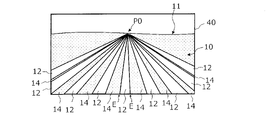
- FIG. 2 is a top view schematically showing a portion of a field in which a plurality of rows of crops are provided on the ground
- 4 is a diagram schematically showing an example of an image acquired by the imaging device of the agricultural machine shown in FIG. 3;
- FIG. 4 is a top view schematically showing a state in which the position and orientation (angle in the yaw direction) of the agricultural machine are adjusted; 6 is a diagram showing an example of an image acquired by the imaging device of the agricultural machine in the state of FIG. 5;
- FIG. 1 is a block diagram showing a basic configuration example of a row detection system according to a first embodiment of the present disclosure;
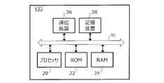
- FIG. 1 is a block diagram schematically showing a configuration example of a processing device according to a first embodiment of the present disclosure;
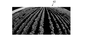
- FIG. It is a monochrome image corresponding to an image of one frame in time-series color images acquired by an on-vehicle camera mounted on a tractor.
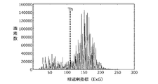
- FIG. 11 is a histogram of the green excess index (ExG) in the image of FIG. 10;
- FIG. 4 is a diagram showing an example of a top-view image (bird's-eye view image) classified into first pixels (for example, crop pixels) and second pixels (background pixels);
- FIG. 3 is a perspective view schematically showing the positional relationship between each of the camera coordinate system ⁇ c1 and the camera coordinate system ⁇ c2 and the reference plane Re.
- FIG. 5 is a schematic diagram showing an example in which the direction of the rows of crops and the direction of the scanning lines in the top view image are parallel; 15 is a diagram schematically showing an example of an integrated value histogram obtained for the top view image of FIG. 14; FIG. FIG. 5 is a schematic diagram showing an example in which the direction of the row of crops and the direction of the scanning line in the top view image intersect; FIG. 17 is a diagram schematically showing an example of an integrated value histogram obtained for the top view image of FIG. 16; 4 is a flow chart illustrating an example algorithm for determining crop row edge lines by a processing device in an embodiment of the present disclosure; FIG. 13 is a diagram showing an integrated value histogram obtained from the top view image of FIG.
- FIG. 12; 4 is a block diagram showing processing executed by a processing device according to an embodiment of the present disclosure
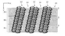
- FIG. FIG. 10 is a diagram for explaining how a top view image is divided into a plurality of blocks
- FIG. 22 is a diagram schematically showing the relationship between the position of a scanning line and the integrated value of index values in each block in FIG. 21
- FIG. 23 is a diagram showing an example of a crop row center in each block in FIG. 22 and an approximate line for the crop row center
- FIG. 24 is a top view showing an example of edge lines of crop rows determined based on the approximation lines of FIG.
- FIG. 26 is a diagram schematically showing the relationship between the position of a scanning line and the integrated value (histogram) of index values in each block in FIG. 25;
- FIG. 27 is a diagram showing an example of a crop row center in each block in FIG. 26 and an approximate line for the crop row center;
- FIG. 28 is a top view showing an example of edge lines of crop rows determined based on the approximate curve of FIG. 27;
- FIG. 26 is a diagram schematically showing the relationship between the position of a scanning line and the integrated value (histogram) of index values in each block in FIG. 25;
- FIG. 27 is a diagram showing an example of a crop row center in each block in FIG. 26 and an approximate line for the crop row center;
- FIG. 28 is a top view showing an example of edge lines of crop rows determined based on the approximate curve of FIG. 27;
- FIG. 4 is a perspective view schematically showing rows of ridges provided on the ground; It is a figure which shows the image acquired at the time t from the imaging device.
- FIG. 10 is a diagram schematically showing a correspondence relationship of feature points between an image acquired from an imaging device at time t and an image acquired at time t+1;
- FIG. 4 is a perspective view schematically showing movement of feature points on ridges and intermediate areas (work passages) appearing in an image acquired by an imaging device;
- FIG. 3 is a diagram schematically showing the relationship between the amount of movement (first amount of movement) of feature points projected onto an image plane and the amount of movement (second amount of movement) of feature points projected onto a reference plane;
- FIG. 7 is a block diagram showing processing executed by a processing device according to the second embodiment of the present disclosure
- FIG. 4 is a diagram showing the relationship between the average height of feature points on a scanning line and the position of the scanning line
- FIG. 11 is a diagram showing a basic configuration example of a row detection system according to a third embodiment of the present disclosure
- FIG. It is a figure which shows the example of the image which the processing apparatus acquired from the imaging device.
- Figure 38 shows a portion of the image of Figure 37
- FIG. 4 is a top view schematically showing part of the ground on which rows of crops are provided;
- Agricultural machinery in the present disclosure broadly includes machines that perform basic agricultural work such as “plowing”, “planting”, and “harvesting” in fields.
- Agricultural machines are machines having functions and structures for performing agricultural work such as tillage, sowing, pest control, fertilization, planting of crops, or harvesting on the ground in a field. These agricultural operations are sometimes referred to as “ground operations” or simply “operations.”
- the agricultural machine does not need to be equipped with a travel device for moving itself, and may travel by being attached to or towed by another vehicle equipped with a travel device.
- a work vehicle such as a tractor functions alone as an "agricultural machine”
- the work machine (implement) attached to or towed by the work vehicle and the work vehicle as a whole can be regarded as one "agricultural machine”. It may work.
- Examples of agricultural machinery include tractors, riding machines, vegetable transplanters, mowers, and field mobile robots.
- the row detection system in this embodiment includes an imaging device that is attached to an agricultural machine and used.
- the imaging device is fixed to the agricultural machine so as to photograph the ground on which the agricultural machine travels and acquire time-series color images including at least a portion of the ground.
- FIG. 1 schematically shows how an imaging device 120 attached to an agricultural machine 100 such as a tractor or a riding management machine captures an image of the ground 10 .
- the agricultural machine 100 includes a vehicle body 110 that can travel, and an imaging device 120 is fixed to the vehicle body 110 .
- FIG. 1 shows a body coordinate system ⁇ b having mutually orthogonal Xb-, Yb-, and Zb-axes.
- the body coordinate system ⁇ b is a coordinate system fixed to the agricultural machine 100, and the origin of the body coordinate system ⁇ b can be set near the center of gravity of the agricultural machine 100, for example. In the drawing, for ease of viewing, the origin of the body coordinate system ⁇ b is shown as being positioned outside the agricultural machine 100 .
- the Xb axis coincides with the traveling direction (the direction of arrow F) when the agricultural machine 100 travels straight.
- the Yb axis coincides with the rightward direction when the positive direction of the Xb axis is viewed from the coordinate origin, and the Zb axis coincides with the vertically downward direction.
- the imaging device 120 is, for example, an in-vehicle camera having a CCD (Charge Coupled Device) or CMOS (Complementary Metal Oxide Semiconductor) image sensor.
- the imaging device 120 in this embodiment is, for example, a monocular camera capable of capturing moving images at a frame rate of 3 frames per second (fps) or higher.
- FIG. 2 is a perspective view schematically showing the relationship between the body coordinate system ⁇ b, the camera coordinate system ⁇ c of the imaging device 120, and the world coordinate system ⁇ w fixed to the ground 10 described above.
- the camera coordinate system ⁇ c has mutually orthogonal Xc, Yc, and Zc axes
- the world coordinate system ⁇ w has mutually orthogonal Xw, Yw, and Zw axes.
- the Xw-axis and Yw-axis of the world coordinate system ⁇ w are on the reference plane Re extending along the ground 10 .
- the imaging device 120 is attached to a predetermined position of the agricultural machine 100 so as to face a predetermined direction. Therefore, the position and orientation of the camera coordinate system ⁇ c with respect to the body coordinate system ⁇ b are fixed in a known state.
- the Zc axis of the camera coordinate system ⁇ c is on the camera optical axis ⁇ 1.
- the camera optical axis ⁇ 1 is inclined from the traveling direction F of the agricultural machine 100 toward the ground 10, and the depression angle ⁇ is greater than 0°.
- a travel direction F of the agricultural machine 100 is generally parallel to the ground 10 on which the agricultural machine 100 travels.
- the depression angle ⁇ can be set, for example, within a range of 0° or more and 60° or less. When the position where the imaging device 120 is attached is close to the ground 10, the angle of depression ⁇ may be set to a negative value, in other words, the orientation of the camera optical axis ⁇ 1 may be set to have a positive elevation angle.
- the body coordinate system ⁇ b and the camera coordinate system ⁇ c translate with respect to the world coordinate system ⁇ w.
- the body coordinate system ⁇ b and the camera coordinate system ⁇ c may rotate with respect to the world coordinate system ⁇ w.
- the agricultural machine 100 does not rotate in the pitch and roll directions and moves substantially parallel to the ground 10 .
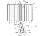
- FIG. 3 is a top view schematically showing a portion of a field in which a plurality of rows of crops 12 are provided on the ground 10.
- the crop row 12 is a row formed by continuously planting crops in one direction on the ground 10 of a field.
- a crop row 12 is a collection of crops planted on a ridge of a field.
- the width of the crop row 12 varies as the crop grows.
- An intermediate region 14 in which no crops are planted exists in a belt shape between adjacent rows of crops 12 .
- Each intermediate region 14 is a region sandwiched between two opposing edge lines E between two adjacent crop rows 12 .
- a plurality of rows of crops 12 are formed on one ridge. That is, a plurality of crop rows 12 are formed between rows of ridges.
- the edge line E of the row of crops 12 positioned at the edge in the width direction of the ridge serves as the reference for the intermediate region 14 . That is, the intermediate region 14 is located between the edge lines E of the row of crops 12 positioned at the edge in the width direction of the ridge among the edge lines E of the row of crops 12 .
- the intermediate area 14 functions as an area (work passage) through which the wheels of the agricultural machine 100 pass, the "intermediate area” may be referred to as a "work passage”.
- the "edge line" of the crop row means a reference line segment (which may include curved lines) for defining the target route when the agricultural machine travels.
- Such reference line segments can be defined as the ends of a strip-shaped area (working path) through which the wheels of the agricultural machine are allowed to pass.
- the processing device 122 in FIG. 7 generates an image (enhanced image) in which the color of the crop row to be detected is enhanced, based on the time-series color images acquired from the imaging device 120 .
- Crops have chlorophyll (chlorophyll) in order to receive sunlight (white light) and perform photosynthesis. Chlorophyll absorbs less green light than red and blue light. Therefore, the spectrum of sunlight reflected by crops exhibits relatively high values in the green wavelength range compared to the spectrum of sunlight reflected by the soil surface. As a result, crop color generally has a high green component and the "crop row color” is typically green. However, as will be described later, the "crop row color” is not limited to green.
- NDVI Normalized Difference Vegetation Index
- the homography transformation By using such a homography transformation, it is possible to generate a top view image of the ground from the image of the ground acquired by the imaging device in the first posture (the imaging device attached to the agricultural machine).
- the coordinates of an arbitrary point on the image plane Im1 of the imaging device 120 are converted to the image plane Im2 of a virtual imaging device in a predetermined orientation with respect to the reference plane Re. Can be converted to point coordinates.
- the processing device 122 in this embodiment classifies the first pixels having the index value of the color of the row of crops above the threshold value and the second pixels having the index value less than the threshold value from above the ground by the above-described method. After generating the seen top view image, operation S3 is performed.
- FIG. 14 is an example of a top view image 44 in which three crop rows 12 are shown.
- the crop row 12 direction is parallel to the image vertical direction (v-axis direction).
- FIG. 14 shows a large number of scanning lines (broken lines) S parallel to the image vertical direction (v-axis direction).
- the processing device 122 integrates index values of pixels positioned on a plurality of scanning lines S for each scanning line S to obtain an integrated value.
- the position of the edge line of each crop row 12 is the position of the scanning line S having a value that is 80% of the peak integrated value of each crop row 12 .
- the index values of the color of the crop row on each scanning line S are integrated. That is, the number of first pixels (the number of pixels) is not counted for the binarized top view image based on the classification of the first pixels and the second pixels.
- the count value of the first pixel is increases.
- accumulating the index value of the color of the crop row of the first pixels instead of the number of the first pixels suppresses erroneous determination due to fallen leaves and weeds. , to increase the robustness of column detection.
- FIG. 16 also shows a large number of scanning lines (broken lines) S parallel to the image vertical direction (v-axis direction).
- the processor 122 integrates the index values of the pixels located on the plurality of scanning lines S for each scanning line S to obtain an integrated value
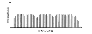
- a histogram of integrated values as shown in FIG. 17 is obtained.
- FIG. 17 is a diagram schematically showing the relationship between the position of the scanning line S and the integrated value of the index values obtained for the top view image of FIG. From this histogram the edge lines of the crop row 12 cannot be determined.
- FIG. 18 is a flowchart showing an example of a procedure for searching for the direction (angle) of the scanning line S parallel to the direction of the crop row 12 by changing the direction (angle) of the scanning line S.
- step S14 from the plurality of histograms obtained in this way, a histogram is selected in which the boundaries of the unevenness are steep and the crop row 12 is clearly separated from the intermediate region 14 as shown in FIG. Find the angle ⁇ of the scan line S that produces .
- the crop row that should be accurately detected is the center or periphery of the image. Therefore, distortion in regions near the left and right ends of the top view image can be ignored.
- the target path can be generated so that the central portion of the tire in the width direction passes through the middle of two edge lines positioned at both ends of the intermediate region (working passage) 14 . According to such a target route, even if the agricultural machine deviates from the target route by several centimeters during travel, it is possible to reduce the possibility that the tires will enter the crop row.
- the embodiments of the present disclosure it is possible to suppress the effects of weather conditions such as front light, backlight, fine weather, cloudy weather, and fog, and sunlight conditions that change depending on the working hours, and to detect crop rows with high accuracy. It was confirmed.
- the crop type cabbage, broccoli, radish, carrot, lettuce, Chinese cabbage, etc.
- growth state from seedling to mature state
- presence of disease presence of fallen leaves/weeds
- robustness even when soil color changes
- the homography transformation is performed after the step of obtaining the threshold value for binarization and extracting the crop area using pixels equal to or higher than the threshold value.
- the step of extracting crop regions may be performed after the homography transformation.
- homography transformation 35 may be performed between enhanced image generation 33 and crop row extraction 34, or between image acquisition 32 and enhanced image generation 33. may be performed between
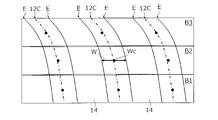
- FIG. 21 is a diagram for explaining a method of dividing part or all of the top view image into a plurality of blocks and determining the position of the edge line for each of the plurality of blocks.
- the processing device 122 divides part or all of the top view image 44 into a plurality of blocks. Then, the position of the edge line E of the crop row 12 is determined for each of the plurality of blocks. In the illustrated example, three blocks B1, B2, and B3 have a belt shape continuous in the horizontal direction of the image in the top view image. The processing device 122 can determine the edge line of the crop row based on the band shape in a direction different from the traveling direction of the agricultural machine 100 .
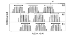
- FIG. 22 is a diagram schematically showing the relationship (integrated value histogram) between the positions of the scanning lines and the integrated values of the index values in each of the blocks B1, B2, and B3 of the top view image in FIG.
- the scan line when performing integration is always parallel to the image vertical direction.
- the index values are integrated block by block, and there is no need to change the direction (angle) of the scanning line.
- By shortening the length of the scanning line S it is possible to appropriately detect the area of the second pixels (background pixels) caused by the intermediate area (working path) 14 even if the crop row 12 extends obliquely. become. Therefore, there is no need to change the angle of the scanning line S.
- Both ends of the arrow W in FIG. 22 indicate the positions of the crop row edge lines determined in each of the blocks B1, B2, and B3.
- the crop row 12 direction is slanted with respect to the scan line S direction. Therefore, as described above, when a scanning line position showing a value 0.8 times the peak value of the integrated value histogram is adopted as the position of the edge line E of the crop row 12, such an edge line E corresponds to both ends of the "width" passing near the center of the crop row 12 in each of the blocks B1, B2, and B3.
- FIG. 23 shows the crop row center Wc in each of blocks B1, B2, and B3 in FIG.
- the crop row center Wc is obtained from the center of the arrow W that defines the edge line of the crop row obtained from the integrated value histogram in FIG. 22, and is located at the center of each block in the image vertical direction.
- FIG. 23 shows an example of the approximation line 12C for the crop row center Wc belonging to the same crop row 12.
- the approximation line 12C is, for example, a straight line obtained so as to minimize the root mean square distance (error) from the plurality of crop row centers Wc of each crop row 12 .
- Such an approximation line 12C corresponds to a line passing through the center of the crop row 12.
- FIG. 23 shows the crop row center Wc in each of blocks B1, B2, and B3 in FIG.
- the crop row center Wc is obtained from the center of the arrow W that defines the edge line of the crop row obtained from the integrated value histogram in FIG. 22, and is located at the
- FIG. 24 is a top view showing an example of the edge line E of the row of crops 12 determined from the approximation line 12C of FIG.
- the two edge lines E associated with each crop row 12 are spaced equal to the length of the arrow W and equidistant from the approximation line 12C.
- the edge line E of the crop row 12 can be obtained with a smaller amount of calculation without changing the direction (angle) of the scanning line.
- the length of each block in the image vertical direction can be set to correspond to a distance of 1 to 2 meters on the ground, for example.
- one image is divided into three blocks to obtain the integrated value histogram, but the number of blocks may be four or more.
- the shape of the block is not limited to the above example.
- a block can have a strip shape that is continuous in either the horizontal direction of the image or the vertical direction of the image in the top view image.
- the processing device 122 can divide the crop into belt-shaped blocks extending in a direction different from the traveling direction of the agricultural machine 100 and determine the edge line of the row of crops.
- FIG. 25 schematically shows how the crop row 12 of the top view image 44 includes a curved portion.
- FIG. 26 schematically shows integrated value histograms in each of blocks B1, B2, and B3 of the top view image 44 of FIG.
- FIG. 27 is a diagram showing an example of the crop row center Wc in each of the blocks B1, B2, and B3 in FIG. 26 and the approximation line 12C for each crop row center Xc.
- the approximation line 12C in this example is, for example, a curve obtained so as to minimize the root mean square of the distance (error) of each crop row 12 from the crop row center Wc (for example, a higher-order curve such as a cubic curve). is.
- Such approximate line 12C corresponds to a curved line passing through the center of crop row 12 having curved portions.
- FIG. 28 is a top view showing an example of the edge line E of the row of crops 12 determined from the approximation line of FIG.
- Edge line E is generated in a manner similar to that described with reference to FIG. That is, the two edge lines E associated with each row of crops 12 are spaced equal to the length of the arrow W and equidistant from the approximation line 12C.
- the top view image is divided into a plurality of blocks and a histogram of integrated values is generated for each block, it becomes easier to determine the direction of the crop row, and the direction of the crop row can be easily obtained. Even if the direction changes on the way, it is possible to know the changed direction.
- Any of the above column detection methods can be implemented by being implemented in a computer and causing the computer to perform desired operations.
- FIG. 29 is a perspective view schematically showing rows of ridges 16 provided on the ground 10.
- FIG. "Ridge” is a place where plants are planted for streaking or streaking, and is a convex portion that extends in a substantially straight line, with soil piled high at intervals.
- the cross-sectional shape of the ridges 16, perpendicular to the direction in which the ridges 16 extend, can be generally trapezoidal, semicylindrical, or semicircular.
- a ridge 16 having a trapezoidal cross-section is schematically depicted. Real ridges do not have a simple shape as shown in FIG.
- Between two adjacent ridges 16 is an intermediate region 14, called a ridge.
- the intermediate area 14 functions as a working passageway.
- the ridges 16 may be planted with crops or may be unplanted, with only the soil exposed as a whole. Also, each of the ridges 16 may be covered with mulch.
- the height, width and spacing of the ridges 16 do not need to be uniform and may vary from place to place.
- the height of the ridges 16 is generally the difference in height between the ridges.
- the “height” of the ridges 16 is defined by the distance from the reference plane Re described above to the top surface of each ridge 16 .
- the edge lines of the ridges 16 are clear. However, since the actual ridge 16 is a part of the ground 10 that is continuous from the intermediate region 14, and the "cross-sectional shape" of the ridge 16 varies as described above, the boundary between the ridge 16 and the intermediate region 14 is Not always clear.
- the edge lines of the ridges 16, i.e., the boundaries between the ridges 16 and the intermediate regions 14, are located on both sides of the peak of each ridge 16 and have a height that is a predetermined percentage of the peak. defined as a position. The position of the edge line is, for example, 0.8 times the height of the peak of each ridge 16 .
- the row detection system 1000 also includes an imaging device 120 and a processing device 122 that performs image processing on time-series color images acquired from the imaging device 120, as shown in FIG.
- the hardware configuration of the processing device 122 is the same as the configuration of the processing device 122 in the first embodiment.
- the processing device 122 acquires time-series images from the imaging device 120 and performs operations S21, S22, and S23 described below.
- S21 From a plurality of images acquired at different times of the time-series images, a first movement amount within the image plane is obtained for each of the plurality of feature points by feature point matching.
- S22 Each of the plurality of feature points is perspectively projected from the image plane onto a reference plane corresponding to the ground, and a second movement amount of each projection point within the reference plane is obtained based on the first movement amount.
- S23 Based on the second amount of movement, heights of the plurality of feature points from the reference plane are estimated to detect ridges on the ground.
- operation S21 will be described.
- operation S11 from a plurality of images acquired at different times of the time-series images, a first movement amount within the image plane is obtained for each of the plurality of feature points by feature point matching.
- a time-series image is a collection of images acquired in time-series by imaging by the imaging device 120 .
- the time-series images need not be color images, but may be color images.
- the processing device 122 may grayscale the color images to be processed of the time-series color images.
- each image is composed of pixel groups in units of frames.
- the frame rate is also the same as described in the first embodiment.
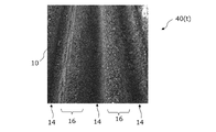
- FIG. 30 is an image 40(t) of one frame in time-series images acquired at time t by the imaging device (monocular camera in this example) 122 mounted on the agricultural machine 100 .
- the imaging device monocular camera in this example
- ridge 16 is not planted with crops. Depth information is not included in the data of the image 40(t) captured by the monocular camera. Therefore, the height difference between the ridge 16 and the intermediate region 14 cannot be known from the single image 40(t).
- the imaging device 120 captures images 40(t+1), 40(t+2), 40(t+3) in chronological order not only at time t but also at other times, such as times t+1, t+2, t+3, . . . , . . .
- a plurality of images acquired in time series by the imaging device 120 while the agricultural machine 100 is running may include the same area of the ground 10 partially overlapping.
- the processing device 122 extracts feature points from the image 40(t), the image 40(t+1), .
- a "feature point” is a point at which the luminance value or color of a pixel distinguishes it from surrounding pixels and allows the location of that pixel to be identified in an image.
- By extracting feature points in images it becomes possible to associate a plurality of images of the same scene with each other. In a region of uniform luminance value and color in an image, it is difficult to distinguish pixels within that region from surrounding pixels. For this reason, feature points are selected from regions in the image that locally vary in brightness value or color.
- a feature point is a pixel or group of pixels that has a "local feature".
- the purpose of extracting feature points in this embodiment is to perform feature point matching from time-series images 40(t), images 40(t+1), . to measure the amount of movement of Extraction of feature points suitable for such feature point matching can be performed by the processing device 122 by image processing.
- feature point extraction algorithms by image processing include SIFT (Scale-invariant feature transform), SURF (Speed-Upped Robust Feature), KAZE, and A-KAZE (ACCELERATED-KAZE).
- SIFT Scale-invariant feature transform
- SURF Speed-Upped Robust Feature
- KAZE KAZE
- A-KAZE ACCELERATED-KAZE
- KAZE and A-KAZE like SIFT or SURF, are highly robust feature point extraction algorithms that are resistant to scaling, rotation, and lighting changes.
- KAZE and A-KAZE unlike SIFT and SURF, do not use Gaussian filters.
- KAZE and A-KAZE are not easily affected by rotation, scale, and changes in brightness values, and can extract feature points even from areas in which brightness values and colors change relatively little in an image. Therefore, it becomes easy to extract feature points suitable for feature point matching even from an image such as the surface of soil.
- A-KAZE has advantages over KAZE in that it is more robust and can increase processing speed.
- feature points are extracted by the A-KAZE algorithm.
- the algorithm for feature point matching is not limited to this example.
- FIG. 31 schematically shows the correspondence relationship of feature points between an image 40(t) acquired from the imaging device at time t and an image 40(t+1) acquired at time t+1.
- the time interval between time t and time t+1 can be, for example, 100 milliseconds or more and 500 seconds.
- a feature point matching algorithm is used to associate the feature points extracted from the image 40(t) with the feature points corresponding to the feature points in the image 40(t+1). .
- eight corresponding feature point pairs are connected by arrows.
- the processing device 122 can extract, for example, several hundred to more than one thousand feature points from each of the image 40(t) and the image 40(t+1) by A-KAZE. The number of feature points to extract can be determined based on the number of images processed per second.
- the processing device 122 After performing such feature point matching, the processing device 122 obtains the amount of movement (first amount of movement) within the image plane for each of the plurality of feature points.
- the first movement amount obtained from the two images 40(t) and 40(t+1) does not have a common value for all feature points.
- the first movement amount shows different values due to the physical height difference of the feature points on the ground 10 .
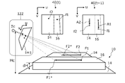
- FIG. 32 is a perspective view schematically showing movement of the ridge 16 and the intermediate region (working passage) 14 appearing in the image acquired by the imaging device 120, and the image 40(t) and the image 40(t+1) are also schematically shown. It is shown.
- FIG. 32 schematically illustrates how point F1 on ridge 16 and point F2 on intermediate area (between ridges or working path) 14 move horizontally to the left of the drawing. This horizontal movement is relative movement caused by the imaging device 120 fixed to the agricultural machine 100 moving to the right along with the agricultural machine 100 .
- FIG. 32 shows that the origin O of the camera coordinate system ⁇ c in the imaging device 120 is stationary and the ground 10 moves leftward.
- the height of the origin O of the camera coordinate system ⁇ c is Hc.
- ridge 16 is a simplified ridge having height dH.
- the image 40(t) of FIG. 32 shows the feature point f1 of the ridge 16 and the feature point f2 of the intermediate region 14. These feature points f1 and f2 are examples of many feature points extracted by a feature point extraction algorithm such as A-KAZE.
- Image 40(t+1) shows feature points f1 and f2 after movement.
- the image 40(t+1) also includes an arrow A1 indicating the movement of the feature point f1 and an arrow A2 indicating the movement of the feature point f2 from time t to t+1.
- the length of arrow A1 (corresponding to the first movement amount) is longer than the length of arrow A2 (corresponding to the first movement amount).
- the movement amount (first movement amount) of the feature point in the image differs depending on the distance from the origin O of the camera coordinate system ⁇ c to the corresponding point of the subject. This is due to the geometric nature of perspective projection.
- the feature points f1 and f2 in the image 40(t) are points obtained by perspectively projecting the points F1 and F2 on the surface of the ground 10, which is the subject, onto the image plane Im1 of the imaging device 120, respectively.
- feature points f1 and f2 in image 40(t+1) are points obtained by perspectively projecting points F1* and F2* on the surface of ground 10, which is the object, onto image plane Im1 of imaging device 120, respectively.
- the center point of the perspective projection is the origin O of the camera coordinate system ⁇ c of the imaging device 120 .
- the points F1 and F2 are points obtained by perspectively projecting the feature points f1 and f2 in the image 40(t) onto the ground 10 .
- the points F1* and F2* can be said to be points obtained by perspectively projecting the feature points f1 and f2 in the image 40(t) onto the ground 10 .
- point F1 on ridge 16 moves to point F1*
- point F2 on intermediate region 14 moves to point F2*. do.
- Each of these movement distances is equal to the distance (horizontal movement distance) traveled by the agricultural machine 100 from time t to time t+1.
- the movement amounts of the feature points f1 and f2 on the image plane Im1 of the imaging device 120 are different from each other.
- FIG. 33 shows the amount of movement (L) of the point F1 on the ridge 16 corresponding to the feature point f1 on the image plane Im1 of the imaging device 120 and the amount of movement of the point (projection point) F1p projected onto the reference plane Re (th 2 is a diagram schematically showing the relationship between the two movement amounts (L+dL).
- the height of the reference plane Re is matched with the height of the intermediate region (between ridges) 14, and the height of the ridges 16 is dH.
- the point F1 on the ridge 16 has moved to the left by a distance (movement amount) L equal to the running distance of the agricultural machine 100, but the point perspectively projected onto the reference plane Re (projection point ) F1p (second movement amount) is represented by L+dL, which is longer than L.
- L the distance
- F1p second movement amount
- the amount of movement (first amount of movement) on the image plane Im1 is also increased corresponding to the extra length dL.
- the processing device 122 in the present embodiment executes operation S22 in order to estimate the size of uneven steps on the ground 10 based on the above formula. That is, each of the plurality of feature points is perspectively projected from the image plane onto the reference plane Re corresponding to the ground 10, and the second movement amount (L+dL) of each projection point within the reference plane Re is based on the first movement amount.
- Ask for Distance L in the above formula can be obtained by measuring the traveling distance of agricultural machine 100 . Also, the height Hc of the origin O of the camera coordinate system from the reference plane Re is known. Therefore, if the second movement amount (L+dL) is known, the height dH of the ridge 16 can be calculated from the equation (7). Then, the second movement amount (L+dL) can be obtained from the first movement amount.
- the processing device 122 executes the operation S23.
- the processing device 122 estimates the height dH of each feature point from the reference plane Re based on the second movement amount (L+dL) of each feature point, and detects the ridges 16 of the ground 10.
- a homography transformation can be utilized. Specifically, the inverse matrix H1-1 of the transformation matrix H1 described above is used to transform the coordinates of each feature point on the image plane Im1 into the coordinates of the corresponding point on the reference plane Re. Therefore, the processing device 122 first obtains the first movement amount from the coordinates before and after movement of each feature point on the image plane Im1. Next, after the coordinates of each feature point are changed to the coordinates of corresponding points on the reference plane Re by homography transformation, the second movement amount can be obtained from the coordinates before and after movement on the reference plane Re.
- a plurality of scanning lines are also set in this embodiment.
- the average feature point height is calculated along each scan line.
- the direction in which the ridge extends can be found from the distribution of the average height values of the feature points.
- the edge lines of the ridges 16 can be determined in a manner similar to the method used to determine the edge lines of the crop row 12 . As described with reference to FIG. 21 and the like, if the method of dividing the image into a plurality of blocks is adopted, the scanning line direction determination 56 can be omitted.
- an image may be divided into a plurality of blocks, and the average value of the heights of feature points on scanning lines may be obtained for each block. .
- the processing device 122 may simultaneously or selectively perform the crop row detection in the first embodiment and the ridge detection in the second embodiment. If the furrow is planted with crops, the processor 122 may function as the crop row detection system in the first embodiment and the furrow detection system in the second embodiment. In that case, the edge lines of the crop row and the edge lines of the furrow are determined. A target path for the agricultural machine can be determined based on both or one of the edge lines.
- the processing device 122 may calculate the reliability of detection for each of crop row detection and ridge detection.
- the reliability of crop row detection may be determined, for example, based on the distribution of integrated values of the index values shown in FIG. 22 or the size of the peak value.
- the reliability of ridge detection may be determined, for example, based on the magnitude of the difference between the maximum value and the minimum value in the height distribution shown in FIG. For example, when a target path is generated based on the detected crop row edge lines and the agricultural machine is traveling along the target path, the crop row detection fails or falls below a predetermined level of confidence. In places of depression, ridge detection may be performed in the background so that target paths are generated based on the edge lines of the ridges.
- the target area for column detection that is, the column search range is limited to a part of the image.
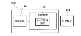
- a row detection system 2000 in this embodiment includes a processing device 122 attached to the agricultural machine 100 .
- the agricultural machine 100 in this embodiment has one or more wheels.
- FIG. 36 shows a basic configuration example of a row detection system 2000 in this embodiment.
- the row detection system 2000 includes a processing device 122 having the same hardware configuration as in other embodiments.
- the processing device 122 selects a search area for detecting at least one of crop rows and ridges from the time-series images. This search area has a size and shape that includes at least a portion of the wheel.
- FIG. 37 shows an example of an image 40 acquired by the processing device 122 from the imaging device 120.
- the image 40 is one piece of time-series images. This image 40 shows the crop row 12, the intermediate region 14, part of the vehicle body 110 of the agricultural machine 100, and part of the front wheel 104F. Edge lines are indicated by white lines in FIG. 37 for reference.
- FIG. 38 is a diagram showing part of the image in FIG. In FIG. 38, part of the vehicle body 110 of the agricultural machine 100 and part of the front wheel 104F shown in the image 40 are surrounded by white lines.
- an example of the search area 60 is indicated by a trapezoidal dashed line that includes a portion of the front wheel 104F.
- the search area 60 has a shape that includes at least one of the crop rows and ridges in the image 40, from the crop row or ridge located on the left side of the front wheel 104F to the crop row or ridge located on the right side. doing.
- distortion is greater in the peripheral portion than in the central portion even in the top view image.
- the peak value decreases and the peak interval widens as the position of the scanning line moves away from the central portion.
- the crop row or ridge to be detected which is necessary for selecting the target route, is near the front of the running agricultural machine. More specifically, it suffices if crop rows or ridges positioned around the wheels of the traveling device of the agricultural machine can be accurately detected.
- the amount of calculations performed by the processing device 122 and the time required for the calculations are reduced by performing column detection on a limited area rather than the entire image acquired by the imaging device 120. becomes possible. It also increases the accuracy of column detection because outliers due to distortions in the periphery of the image can be filtered out.
- the selection (area setting) of the search area 60 depends on the position and orientation of mounting the imaging device 120 on the agricultural machine 100 as well as the structure or shape of the agricultural machine 100 .
- the range (shape, size, position) of the search area 60 may be manually determined while checking the image obtained from the imaging device 120 on the monitor screen. .
- the range of the search area 60 may be determined based on the optical performance of the imaging device 120, the mounting position, the model of the agricultural machine, etc., and input to the processing device 122. FIG.
- the processing device 122 in this embodiment may be configured to detect at least part of the wheel 10F from the image 40 shown in FIG. 38, for example, using image recognition technology. In that case, it is also possible to adaptively change the range of the search area 60 so as to select an area including at least part of the detected front wheel 104F as the search area 60.
- the processing device 122 may estimate the positional relationship between at least one of the detected crop rows 12 and ridges 16 and the front wheels 104F based on a partial image of the front wheels 104F included in the search area 60.
- the processing device 122 may be configured to estimate the positional relationship between at least one of the detected crop rows 12 and ridges 16 and the agricultural machine 100 based on such a positional relationship.
- the processing device 122 may not have information indicating the correct position of the front wheel 104F with respect to the agricultural machine 100 in some cases.
- Information indicating such a position is, for example, the coordinates of the front wheel 104F in the body coordinate system ⁇ b fixed to the agricultural machine 100 . Even if such coordinates are stored in advance in the storage device 28 of the processing device 122, for example, if the user changes the tire size of the front wheels 104F or changes the distance between the left and right front wheels 104F, the accuracy of the coordinates will be reduced. is lost.
- the processing device 122 detects a portion of the front wheel 104F included in the search area 60, and estimates the position of the front wheel 104F relative to the agricultural machine 100 based on the image of the detected portion of the front wheel 104F. good too.
- FIG. 39 is a top view schematically showing part of the ground 10 on which the crop row 12 is provided.
- FIG. 39 shows a pair of front wheels 104F.
- Such a top-view rectangular area 62 is a top-view image generated by performing the aforementioned homographic transformation on the search area 60 of the image of FIG.
- the vehicle body 110 shown in the search area 60 of FIG. 38 is omitted.
- FIG. 39 schematically shows a tire tread (ground contact surface) CA where the front wheel 104F contacts the ground 10.
- the center-to-center distance T of the left and right tire treads CA is the "tread width (track)."
- the position of the tire tread CA with respect to the vehicle body 110 of the agricultural machine 100 is known. Therefore, the positional relationship of the tire tread CA with respect to the top view image (rectangular area) 62 of the search area 60 is also known.
- the search area 60 is set to include at least part of one or a plurality of wheels as in this embodiment, the following effects can be obtained.
- the structure of the vehicle body 110 differs depending on the model, and the tread width (distance between the centers of the tire treads CA) T may also differ depending on the model. Further, even if the model is the same, the user may change the tread width T as described above.
- the shape and size of the search area 60 so as to include the wheel 104 in the image, it is possible to realize image processing that can be applied to various models, and to change the tread width T by the user. make it responsive. - It is no longer essential to input the position of the tire tread CA in advance as the coordinates of the body coordinate system ⁇ b. Based on the image acquired by the imaging device 120, it is possible to automatically acquire the coordinates of the front wheel 104F or the tire tread CA in the body coordinate system ⁇ b. • Allows image-based monitoring of the edge lines of the row determined by the row detection system or the positional error between the target path generated on the basis of the edge lines and the wheel.
- the X coordinates and Y coordinates of the corresponding points P3′ and P4′ on the reference plane Re are the X coordinates of the points P3 and P4, respectively. coordinates and Y coordinates. Therefore, when a top view image is generated by performing homography transformation on the image 40 in which a part of the front wheel 104F is reflected, the image of the front wheel 104F is formed in the top view image in a distorted shape, and is positioned accurately. It becomes difficult to infer relationships.
- the agricultural machine in this embodiment includes the row detection system described above.
- this agricultural machine includes a control system that performs control for realizing automatic steering operation.
- a control system is a computer system that includes a storage device and a controller, and is configured to control steering, travel, and other operations of agricultural machinery.
- the processing device of the row detection system can monitor the positional relationship between the edge line of the row and the steering wheel based on the time-series color images. If a position error signal is generated from this positional relationship, the automatic steering system of the agricultural machine can appropriately adjust the steering angle so as to reduce the position error signal.
- FIG. 41 is a perspective view showing an example of the appearance of the agricultural machine 100 according to this embodiment.
- FIG. 42 is a side view schematically showing an example of agricultural machine 100 with work implement 300 attached.
- the agricultural machine 100 in this embodiment is an agricultural tractor (working vehicle) with a working machine 300 attached.
- Agricultural machine 100 is not limited to a tractor, and work machine 300 need not be attached.
- the row detection technology in the present disclosure exhibits excellent effects when used in small-sized tending machines and vegetable transplanters that can be used for inter-row work such as ridge making, intertillage, soiling, weeding, top dressing, and pest control. can be done.
- the agricultural machine 100 includes a vehicle body 110 , a prime mover (engine) 102 and a transmission (transmission) 103 .
- the vehicle body 110 is provided with tires 104 (wheels) and a cabin 105 .
- Tires 104 include a pair of front wheels 104F and a pair of rear wheels 104R.
- a driver's seat 107 , a steering device 106 , an operation terminal 200 , and a group of switches for operation are provided inside the cabin 105 .
- One of the front wheel 104F and the rear wheel 104R may be a crawler instead of a tire.
- the agricultural machine 100 may be a four-wheel drive vehicle having four tires 104 as driving wheels, or a two-wheel drive vehicle having a pair of front wheels 104F or a pair of rear wheels 104R as driving wheels.
- the positioning device 130 in this embodiment includes a GNSS receiver.
- the GNSS receiver includes an antenna for receiving signals from GNSS satellites and processing circuitry for determining the position of agricultural machine 100 based on the signals received by the antenna.
- the positioning device 130 receives GNSS signals transmitted from GNSS satellites and performs positioning based on the GNSS signals.
- GNSS is a general term for satellite positioning systems such as GPS (Global Positioning System), QZSS (Quasi-Zenith Satellite System, eg Michibiki), GLONASS, Galileo, and BeiDou.
- the positioning device 130 in this embodiment is provided in the upper part of the cabin 105, but may be provided in another position.
- an obstacle sensor 136 is provided at the rear portion of the vehicle body 110.
- FIG. Obstacle sensor 136 may be arranged at a portion other than the rear portion of vehicle body 110 .
- one or more obstacle sensors 136 may be provided anywhere on the sides, front, and cabin 105 of the vehicle body 110 .
- the obstacle sensor 136 detects objects existing around the agricultural machine 100 .
- Obstacle sensor 136 may comprise, for example, a laser scanner or ultrasonic sonar.
- the obstacle sensor 136 outputs a signal indicating the presence of an obstacle when an object is present closer than a predetermined distance from the obstacle sensor 136 .
- a plurality of obstacle sensors 136 may be provided at different positions on the vehicle body of the agricultural machine 100 . For example, multiple laser scanners and multiple ultrasonic sonars may be placed at different locations on the vehicle body. By providing such a large number of obstacle sensors 136, blind spots in monitoring obstacles around the agricultural machine 100 can be reduced.
- the prime mover 102 is, for example, a diesel engine.
- An electric motor may be used instead of the diesel engine.
- the transmission 103 can change the driving force and the moving speed of the agricultural machine 100 by shifting.
- the transmission 103 can also switch between forward and reverse of the agricultural machine 100 .
- the steering device 106 includes a steering wheel, a steering shaft connected to the steering wheel, and a power steering device that assists steering by the steering wheel.
- the front wheel 104F is a steerable wheel, and the traveling direction of the agricultural machine 100 can be changed by changing the steering angle (also referred to as "steering angle").
- the steering angle of the front wheels 104F can be changed by operating the steering wheel.
- the power steering system includes a hydraulic system or an electric motor that supplies an assist force for changing the steering angle of the front wheels 104F. When automatic steering is performed, the steering angle is automatically adjusted by the power of the hydraulic system or the electric motor under the control of the control device arranged in the agricultural machine 100 .
- a coupling device 108 is provided at the rear portion of the vehicle body 110 .
- the coupling device 108 includes, for example, a three-point support device (also called a "three-point link” or “three-point hitch"), a PTO (Power Take Off) shaft, a universal joint, and a communication cable.
- the work machine 300 can be attached to and detached from the agricultural machine 100 by the coupling device 108 .
- the coupling device 108 can control the position or attitude of the working machine 300 by elevating the three-point linkage by, for example, a hydraulic device.
- power can be sent from the agricultural machine 100 to the working machine 300 via the universal joint.
- the agricultural machine 100 can cause the work machine 300 to perform a predetermined work while pulling the work machine 300 .
- the coupling device may be provided in front of vehicle body 110 . In that case, a working machine can be connected to the front of the agricultural machine 100 .
- a working machine 300 shown in FIG. 42 is, for example, a rotary cultivator.
- the work machine 300 towed or attached to a work vehicle such as a tractor when traveling along a row can be used for furrow work such as ridge making, intertillage, soiling, weeding, top dressing, pest control, etc.
- furrow work such as ridge making, intertillage, soiling, weeding, top dressing, pest control, etc.
- furrow work such as ridge making, intertillage, soiling, weeding, top dressing, pest control, etc.
- FIG. 43 is a block diagram showing an example of a schematic configuration of agricultural machine 100 and working machine 300. As shown in FIG. Agricultural machine 100 and working machine 300 can communicate with each other via a communication cable included in coupling device 108 .
- the agricultural machine 100 in the example of FIG. 43 includes an imaging device 120, a positioning device 130, an obstacle sensor 136, an operation terminal 200, a driving device 140, a steering wheel sensor 150, a steering angle sensor 152, a control system 160, a communication interface ( IF) 190 , operation switch group 210 , and buzzer 220 .
- Positioning device 130 comprises a GNSS receiver 131 and an inertial measurement unit (IMU) 125 .
- Control system 160 includes storage device 170 and control device 180 .
- the controller 180 comprises a plurality of electronic control units (ECUs) 181-186.
- Work machine 300 includes a drive device 340 , a control device 380 , and a communication interface (IF) 390 .
- FIG. 43 shows constituent elements that are relatively highly relevant to the automatic steering or automatic traveling operation of the agricultural machine 100, and illustration of other constituent elements is omitted.
- the positioning device 130 performs positioning of the agricultural machine 100 using GNSS.
- the positioning device 130 comprises an RTK receiver
- correction signals transmitted from reference stations are utilized in addition to GNSS signals transmitted from multiple GNSS satellites.
- the reference station can be installed around the field on which the agricultural machine 100 runs (for example, within 10 km from the agricultural machine 100).
- the reference station generates a correction signal based on GNSS signals received from multiple GNSS satellites and transmits the correction signal to the positioning device 130 .
- a GNSS receiver 131 in the positioning device 130 receives GNSS signals transmitted from a plurality of GNSS satellites.
- the positioning device 130 performs positioning by calculating the position of the agricultural machine 100 based on the GNSS signals and correction signals.
- RTK-GNSS By using RTK-GNSS, it is possible to perform positioning with an accuracy of, for example, an error of several centimeters.
- Location information including latitude, longitude and altitude information, is obtained through RTK-GNSS high-precision positioning.
- the positioning method is not limited to RTK-GNSS, and any positioning method (interferometric positioning method, relative positioning method, etc.) that can obtain position information with required accuracy can be used. For example, positioning using VRS (Virtual Reference Station) or DGPS (Differential Global Positioning System) may be performed.
- VRS Virtual Reference Station
- DGPS Different Global Positioning System
- the IMU 135 is equipped with a 3-axis acceleration sensor and a 3-axis gyroscope.
- the IMU 135 may include an orientation sensor, such as a 3-axis geomagnetic sensor.
- the IMU 135 functions as a motion sensor and can output signals indicating various quantities such as acceleration, speed, displacement, and attitude of the agricultural machine 100 .
- the positioning device 130 can more accurately estimate the position and orientation of the agricultural machine 100 based on the signals output from the IMU 135 in addition to the GNSS signals and correction signals. Signals output from IMU 135 may be used to correct or impute position calculated based on GNSS signals and correction signals.
- the IMU 135 outputs signals at a higher frequency than GNSS signals.
- the position and orientation of the agricultural machine 100 can be measured at a higher frequency (eg, 10 Hz or higher).
- a separate 3-axis acceleration sensor and 3-axis gyroscope may be provided.
- the IMU 135 may be provided as a separate device from the positioning device 130 .
- the positioning device 130 may include other types of sensors in addition to the GNSS receiver 131 and IMU 135. Depending on the environment in which the agricultural machine 100 runs, the position and orientation of the agricultural machine 100 can be estimated with high accuracy based on the data from these sensors.
- the driving device 140 includes various components necessary for running the agricultural machine 100 and driving the work implement 300, such as the prime mover 102, the transmission 103, the differential including the differential lock mechanism, the steering device 106, and the coupling device .
- Prime mover 102 includes an internal combustion engine, such as a diesel engine, for example.
- Drive system 140 may include an electric motor for traction instead of or in addition to the internal combustion engine.
- the steering wheel sensor 150 measures the rotation angle of the steering wheel of the agricultural machine 100.
- the steering angle sensor 152 measures the steering angle of the front wheels 104F, which are steered wheels. Measured values by the steering wheel sensor 150 and the steering angle sensor 152 are used for steering control by the controller 180 .
- the storage device 170 includes one or more storage media such as flash memory or magnetic disk.
- the storage device 170 stores various data generated by each sensor and the control device 180 .
- the data stored in the storage device 170 may include map data of the environment in which the agricultural machine 100 travels and data of target routes for automatic steering.
- the storage device 170 also stores a computer program that causes each ECU in the control device 180 to execute various operations described later.
- Such a computer program can be provided to the agricultural machine 100 via a storage medium (such as a semiconductor memory or an optical disk) or an electric communication line (such as the Internet).
- Such computer programs may be sold as commercial software.
- the control device 180 includes multiple ECUs.
- the plurality of ECUs include an ECU 181 for image recognition, an ECU 182 for speed control, an ECU 183 for steering control, an ECU 184 for automatic steering control, an ECU 185 for work machine control, an ECU 186 for display control, and an ECU 187 for buzzer control.
- the image recognition ECU 181 functions as a processing device for the row detection system.
- ECU 182 controls the speed of agricultural machine 100 by controlling prime mover 102 , transmission 103 and brakes included in drive system 140 .
- the ECU 183 controls steering of the agricultural machine 100 by controlling a hydraulic device or an electric motor included in the steering device 106 based on the measurement value of the steering wheel sensor 150 .
- ECU 184 performs calculations and controls for realizing automatic steering operation based on signals output from positioning device 130 , steering wheel sensor 150 , and steering angle sensor 152 .
- the ECU 184 sends an instruction to change the steering angle to the ECU 183 .
- the ECU 183 changes the steering angle by controlling the steering device 106 in response to the command.
- ECU 185 controls the operation of coupling device 108 in order to cause work machine 300 to perform a desired operation.
- ECU 185 also generates a signal for controlling the operation of work machine 300 and transmits the signal to work machine 300 via communication IF 190 .
- ECU 186 controls the display of operation terminal 200 .
- the ECU 186 causes the display device of the operation terminal 200 to display various displays such as a field map, detected crop rows or ridges, the position and target route of the agricultural machine 100 in the map, pop-up notifications, and setting screens.
- ECU 187 controls the output of a warning sound by buzzer 220 .
- control device 180 realizes driving by manual steering or automatic steering.
- control device 180 controls drive device 140 based on the position of agricultural machine 100 measured or estimated by positioning device 130 and the target route stored in storage device 170 .
- the control device 180 causes the agricultural machine 100 to travel along the target route.
- the ECU 181 for image recognition determines edge lines of crop rows or ridges from the detected crop rows or ridges, and generates a target route based on these edge lines. .
- the controller 180 performs operations according to this target path.
Landscapes
- Engineering & Computer Science (AREA)
- Physics & Mathematics (AREA)
- General Physics & Mathematics (AREA)
- Theoretical Computer Science (AREA)
- Life Sciences & Earth Sciences (AREA)
- Computer Vision & Pattern Recognition (AREA)
- Environmental Sciences (AREA)
- Soil Sciences (AREA)
- Mechanical Engineering (AREA)
- Automation & Control Theory (AREA)
- Radar, Positioning & Navigation (AREA)
- Remote Sensing (AREA)
- Aviation & Aerospace Engineering (AREA)
- Multimedia (AREA)
- General Health & Medical Sciences (AREA)
- Health & Medical Sciences (AREA)
- Geometry (AREA)
- Guiding Agricultural Machines (AREA)
- Control Of Position, Course, Altitude, Or Attitude Of Moving Bodies (AREA)
Priority Applications (5)
| Application Number | Priority Date | Filing Date | Title |
|---|---|---|---|
| KR1020237042411A KR20240005917A (ko) | 2021-06-29 | 2022-02-04 | 열 검출 시스템, 열 검출 시스템을 구비하는 농업 기계, 및 열 검출 방법 |
| EP22832395.2A EP4335266B1 (en) | 2021-06-29 | 2022-02-04 | Row detection system, agricultural machine provided with row detection system, and method for detecting row |
| JP2023531367A JP7767423B2 (ja) | 2021-06-29 | 2022-02-04 | 列検出システム、列検出システムを備える農業機械、および、列検出方法 |
| US18/392,262 US12588578B2 (en) | 2021-06-29 | 2023-12-21 | Row detection system, agricultural machine having a row detection system, and method of row detection |
| JP2025095776A JP2025128274A (ja) | 2021-06-29 | 2025-06-09 | 列検出システム、列検出システムを備える農業機械、および、列検出方法 |
Applications Claiming Priority (2)
| Application Number | Priority Date | Filing Date | Title |
|---|---|---|---|
| JP2021107920 | 2021-06-29 | ||
| JP2021-107920 | 2021-06-29 |
Related Child Applications (1)
| Application Number | Title | Priority Date | Filing Date |
|---|---|---|---|
| US18/392,262 Continuation US12588578B2 (en) | 2021-06-29 | 2023-12-21 | Row detection system, agricultural machine having a row detection system, and method of row detection |
Publications (1)
| Publication Number | Publication Date |
|---|---|
| WO2023276227A1 true WO2023276227A1 (ja) | 2023-01-05 |
Family
ID=84691057
Family Applications (1)
| Application Number | Title | Priority Date | Filing Date |
|---|---|---|---|
| PCT/JP2022/004548 Ceased WO2023276227A1 (ja) | 2021-06-29 | 2022-02-04 | 列検出システム、列検出システムを備える農業機械、および、列検出方法 |
Country Status (5)
| Country | Link |
|---|---|
| US (1) | US12588578B2 (https=) |
| EP (1) | EP4335266B1 (https=) |
| JP (2) | JP7767423B2 (https=) |
| KR (1) | KR20240005917A (https=) |
| WO (1) | WO2023276227A1 (https=) |
Cited By (3)
| Publication number | Priority date | Publication date | Assignee | Title |
|---|---|---|---|---|
| WO2024095993A1 (ja) | 2022-11-02 | 2024-05-10 | 株式会社クボタ | 列検出システム、列検出システムを備える農業機械、および列検出方法 |
| WO2024095802A1 (ja) | 2022-11-02 | 2024-05-10 | 株式会社クボタ | 走行制御システム、作業車両および走行制御方法 |
| JP2025002839A (ja) * | 2023-06-23 | 2025-01-09 | 株式会社クボタ | 列検出システムおよび農業機械 |
Families Citing this family (5)
| Publication number | Priority date | Publication date | Assignee | Title |
|---|---|---|---|---|
| EP4335265A4 (en) * | 2021-06-29 | 2025-06-11 | Kubota Corporation | Crop row detection system, agricultural machine equipped with crop row detection system, and crop row detection method |
| WO2023127437A1 (ja) * | 2021-12-27 | 2023-07-06 | 株式会社クボタ | 農業機械 |
| WO2023230292A1 (en) * | 2022-05-26 | 2023-11-30 | farm-ng Inc. | Image segmentation for row following and associated training system |
| KR20240165191A (ko) * | 2023-05-15 | 2024-11-22 | 현대자동차주식회사 | 객체 높이 판단 장치 및 그 방법 |
| CN121089710B (zh) * | 2025-09-01 | 2026-04-28 | 湖南省水利水电科学研究院 | 一种砍青机器人导航方法及系统 |
Citations (4)
| Publication number | Priority date | Publication date | Assignee | Title |
|---|---|---|---|---|
| US20070001096A1 (en) * | 2005-07-01 | 2007-01-04 | Jiantao Wei | Method and system for vehicular guidance using a crop image |
| JP2013201958A (ja) * | 2012-03-28 | 2013-10-07 | National Agriculture & Food Research Organization | 走行制御装置 |
| JP2016146061A (ja) * | 2015-02-06 | 2016-08-12 | 国立研究開発法人農業・食品産業技術総合研究機構 | 走行制御装置 |
| JP2016208871A (ja) | 2015-04-30 | 2016-12-15 | 国立大学法人 鹿児島大学 | 作業機及びその制御方法 |
Family Cites Families (2)
| Publication number | Priority date | Publication date | Assignee | Title |
|---|---|---|---|---|
| JP2593166B2 (ja) | 1987-12-18 | 1997-03-26 | ヤンマー農機株式会社 | 農作業機における植付苗列検出装置 |
| US12315247B2 (en) * | 2021-12-01 | 2025-05-27 | Deere & Company | Generating synthetic ground-level data based on generator conditioned for particular agricultural area |
-
2022
- 2022-02-04 JP JP2023531367A patent/JP7767423B2/ja active Active
- 2022-02-04 KR KR1020237042411A patent/KR20240005917A/ko active Pending
- 2022-02-04 WO PCT/JP2022/004548 patent/WO2023276227A1/ja not_active Ceased
- 2022-02-04 EP EP22832395.2A patent/EP4335266B1/en active Active
-
2023
- 2023-12-21 US US18/392,262 patent/US12588578B2/en active Active
-
2025
- 2025-06-09 JP JP2025095776A patent/JP2025128274A/ja not_active Withdrawn
Patent Citations (4)
| Publication number | Priority date | Publication date | Assignee | Title |
|---|---|---|---|---|
| US20070001096A1 (en) * | 2005-07-01 | 2007-01-04 | Jiantao Wei | Method and system for vehicular guidance using a crop image |
| JP2013201958A (ja) * | 2012-03-28 | 2013-10-07 | National Agriculture & Food Research Organization | 走行制御装置 |
| JP2016146061A (ja) * | 2015-02-06 | 2016-08-12 | 国立研究開発法人農業・食品産業技術総合研究機構 | 走行制御装置 |
| JP2016208871A (ja) | 2015-04-30 | 2016-12-15 | 国立大学法人 鹿児島大学 | 作業機及びその制御方法 |
Non-Patent Citations (4)
| Title |
|---|
| OKAMOTO HIROSHI, SHUN-ICHI HATA, MUNEHIRO TAKAI: "Crop-Row Detector for Row-following Control Systems (part 1); Comparison and Evaluation of Detecting Systems", JOURNAL OF THE JAPANESE SOCIETY OF AGRICULTURAL MACHINERY, vol. 61, no. 6, 1 November 1999 (1999-11-01), pages 159 - 167, XP093018518, DOI: 10.11357/jsam1937.61.6_159 * |
| OKAMOTO HIROSHI, SHUN-ICHI HATA, MUNEHIRO TAKAI: "Visual Sensor for Crop-Row Following Robot", LECTURE ABSTRACTS OF THE 58TH JAPANESE SOCIETY OF AGRICULTURAL MACHINERY, 1 April 1999 (1999-04-01), pages 231 - 231, XP093018519, DOI: 10.11357/jsam1937.61.Supplement_231 * |
| See also references of EP4335266A4 |
| TIAN FENG, HUA MINLEI, ZHANG WENRUI, LI YINGJIE, YANG XIAOLI: "Emotional arousal in 2D versus 3D virtual reality environments", PLOS ONE, vol. 16, no. 9, pages e0256211, XP093018936, DOI: 10.1371/journal.pone.0256211 * |
Cited By (4)
| Publication number | Priority date | Publication date | Assignee | Title |
|---|---|---|---|---|
| WO2024095993A1 (ja) | 2022-11-02 | 2024-05-10 | 株式会社クボタ | 列検出システム、列検出システムを備える農業機械、および列検出方法 |
| WO2024095802A1 (ja) | 2022-11-02 | 2024-05-10 | 株式会社クボタ | 走行制御システム、作業車両および走行制御方法 |
| JP2025002839A (ja) * | 2023-06-23 | 2025-01-09 | 株式会社クボタ | 列検出システムおよび農業機械 |
| US12488586B2 (en) | 2023-06-23 | 2025-12-02 | Kubota Corporation | Row detection system and agricultural machine |
Also Published As
| Publication number | Publication date |
|---|---|
| JP2025128274A (ja) | 2025-09-02 |
| KR20240005917A (ko) | 2024-01-12 |
| US20240196781A1 (en) | 2024-06-20 |
| EP4335266A1 (en) | 2024-03-13 |
| EP4335266A4 (en) | 2025-05-14 |
| US12588578B2 (en) | 2026-03-31 |
| EP4335266B1 (en) | 2026-01-14 |
| JPWO2023276227A1 (https=) | 2023-01-05 |
| JP7767423B2 (ja) | 2025-11-11 |
Similar Documents
| Publication | Publication Date | Title |
|---|---|---|
| JP7572555B2 (ja) | 列検出システム、列検出システムを備える農業機械、および、列検出方法 | |
| JP7767423B2 (ja) | 列検出システム、列検出システムを備える農業機械、および、列検出方法 | |
| JP7796745B2 (ja) | 作物列検出システム、作物列検出システムを備える農業機械、および、作物列検出方法 | |
| US7792622B2 (en) | Method and system for vehicular guidance using a crop image | |
| US7684916B2 (en) | Method and system for vehicular guidance using a crop image | |
| US7570783B2 (en) | Method and system for vehicular guidance using a crop image | |
| US12488586B2 (en) | Row detection system and agricultural machine | |
| WO2023127437A1 (ja) | 農業機械 | |
| US20240315159A1 (en) | Agricultural machine | |
| JP2006101816A (ja) | 操向制御方法及び装置 | |
| JP7821820B2 (ja) | 農業機械 | |
| US12620237B2 (en) | Agricultural machine | |
| US20250268118A1 (en) | Row detection system, agricultural machine provided with row detection system, and row detection method | |
| US20250255205A1 (en) | Driving control system, work vehicle, and driving control method | |
| Rovira Más et al. | Local Perception Systems | |
| Más et al. | Local Perception Systems |
Legal Events
| Date | Code | Title | Description |
|---|---|---|---|
| 121 | Ep: the epo has been informed by wipo that ep was designated in this application |
Ref document number: 22832395 Country of ref document: EP Kind code of ref document: A1 |
|
| WWE | Wipo information: entry into national phase |
Ref document number: 2023531367 Country of ref document: JP |
|
| ENP | Entry into the national phase |
Ref document number: 20237042411 Country of ref document: KR Kind code of ref document: A |
|
| WWE | Wipo information: entry into national phase |
Ref document number: 1020237042411 Country of ref document: KR Ref document number: 2022832395 Country of ref document: EP |
|
| ENP | Entry into the national phase |
Ref document number: 2022832395 Country of ref document: EP Effective date: 20231207 |
|
| WWE | Wipo information: entry into national phase |
Ref document number: 2301008314 Country of ref document: TH |
|
| WWE | Wipo information: entry into national phase |
Ref document number: 202317087621 Country of ref document: IN |
|
| NENP | Non-entry into the national phase |
Ref country code: DE |
|
| WWG | Wipo information: grant in national office |
Ref document number: 2022832395 Country of ref document: EP |