WO2023275984A1 - 仮想化システム復旧装置及び仮想化システム復旧方法 - Google Patents
仮想化システム復旧装置及び仮想化システム復旧方法 Download PDFInfo
- Publication number
- WO2023275984A1 WO2023275984A1 PCT/JP2021/024528 JP2021024528W WO2023275984A1 WO 2023275984 A1 WO2023275984 A1 WO 2023275984A1 JP 2021024528 W JP2021024528 W JP 2021024528W WO 2023275984 A1 WO2023275984 A1 WO 2023275984A1
- Authority
- WO
- WIPO (PCT)
- Prior art keywords
- cluster
- container
- anomaly
- detection unit
- clusters
- Prior art date
- Legal status (The legal status is an assumption and is not a legal conclusion. Google has not performed a legal analysis and makes no representation as to the accuracy of the status listed.)
- Ceased
Links
Images







Classifications
-
- G—PHYSICS
- G06—COMPUTING OR CALCULATING; COUNTING
- G06F—ELECTRIC DIGITAL DATA PROCESSING
- G06F11/00—Error detection; Error correction; Monitoring
- G06F11/07—Responding to the occurrence of a fault, e.g. fault tolerance
Definitions
- the present invention relates to a virtualization system recovery device and a virtualization system recovery method for realizing abnormality detection and failure recovery of containers and applications operating on containers in a computing infrastructure based on virtual machines and containers.
- the virtual machine mentioned above is a computer that realizes the same functions as a physical computer with software.
- a container is a virtualization technology created by packaging an application in an environment called a "container" and running on a container engine.
- anomaly detection and failure recovery of containers and applications running on containers are realized mainly by Liveness/Readiness Probe functions (also called probe functions) of kubernetes, which will be described later. ing.
- Kubernetes is container virtualization software that creates and clusters containers such as Docker, and is open source software.
- the Liveness Probe function performs control such as restarting the container, and the Readiness Probe function performs control such as whether or not the container accepts requests.
- the failure monitoring cycle can only be set to a predetermined slow cycle such as 1 second. Therefore, when it is necessary to detect anomalies and recover from failures as quickly as possible, there is a problem that it is not possible to detect anomalies and recover from anomalies faster than the anomaly detection and recovery functions of Kubernetes in the default state.
- the present invention has been made in view of such circumstances, and an object of the present invention is to detect anomalies and recover from failures occurring in a virtualization system faster than the anomaly detection and recovery functions of container virtualization software. do.
- the virtualized system recovery device of the present invention is a computing resource cluster that is virtually created on a physical machine by container virtualization software, and clusters and arranges the virtualized containers.
- a cluster management unit that manages the placement and operation of the virtually created clustered containers, and a plurality of cluster management units, each of which includes the computing resource cluster and the cluster management unit a cluster, an internal anomaly detection unit that is arranged for each of the plurality of clusters and that is virtually created outside the virtually created computational resource cluster and cluster management unit that detects an anomaly in the container; and an external anomaly detection unit that is virtually created outside the plurality of clusters and detects an anomaly in the cluster in which the abnormal container is arranged when the internal anomaly detection unit detects an anomaly in the container.
- anomaly detection and failure recovery can be performed faster than the anomaly detection and recovery function of container virtualization software when a failure occurs in a virtualization system.
- FIG. 1 is a block diagram showing the configuration of a virtualization system restoration device according to an embodiment of the present invention
- FIG. FIG. 10 is a block diagram showing a configuration when an endpoint setting unit and a Pod are deployed as a 1:1 configuration by a failure deployment instruction unit in the virtualization system recovery device of the present embodiment
- FIG. 11 is a block diagram for explaining first container abnormality detection processing by the Pod of the virtualization system restoration device of the present embodiment
- FIG. 11 is a block diagram for explaining second anomaly detection processing by a routing table provided for each worker node of the virtualization system restoration device of this embodiment
- FIG. 11 is a block diagram for explaining third anomaly detection processing by monitoring daemons of virtual switches provided for each worker node of the virtualization system restoration device of the present embodiment
- FIG. 11 is a block diagram for explaining fourth anomaly detection processing by monitoring daemons of container runtime provided for each worker node of the virtualization system recovery device of the present embodiment
- FIG. 14 is a block diagram for explaining fifth anomaly detection processing by monitoring each worker node of the virtualization system restoration device of the present embodiment
- FIG. 11 is a block diagram for explaining sixth anomaly detection processing by monitoring a DB externally attached to a cluster of a container system of the virtualization system recovery device of the present embodiment
- FIG. 11 is a block diagram showing a configuration for explaining anomaly detection processing related to occurrence of failures in a plurality of clusters by an external anomaly detection unit
- FIG. 4 is a block diagram for explaining anomaly handling processing of the virtualization system recovery device of the present embodiment
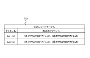
- FIG. 4 is a diagram showing the correspondence relationship between domain names and resolution destination IP addresses in a DNS record table;
- FIG. 10 illustrates how IP addresses of faulty clusters are deleted from the DNS record table;
- 4 is a flowchart for explaining the operation of the abnormality handling process of the virtualization system restoration device of the present embodiment;
- FIG. 4 is a block diagram showing the configuration of a virtualization system restoration device according to Modification 1 of the embodiment of the present invention;
- FIG. 11 is a block diagram showing the configuration of a virtualization system restoration device according to Modification 2 of the embodiment of the present invention;
- FIG. 2 is a hardware configuration diagram showing an example of a computer that implements the functions of the virtualization system recovery device according to the present embodiment;
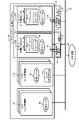
- FIG. 1 is a block diagram showing the configuration of a virtualization system restoration device according to an embodiment of the present invention.
- the container system 20 shown in FIG. 1 is a virtualization system configured by a plurality of clusters (in this example, a first cluster 12A and a second cluster 12B) in which containers are clustered.
- the first cluster 12A is composed of a cluster manager 14A and a computational resource cluster 15A.
- the second cluster 12B is composed of a cluster manager 14B and a computational resource cluster 15B.
- the cluster management units 14A and 14B include a communication distribution unit 14a, a computational resource operation unit 14b, a computational resource management unit 14c, a container configuration reception unit 14d, a container placement destination determination unit 14e, and a container management unit 14f. configured with.
- the computational resource clusters 15A, 15B are configured with a plurality of applications 15a, 15b.
- the cluster management units 14A and 14B are also called the cluster management unit 14, and the computational resource clusters 15A and 15B are also called the computational resource cluster 15.
- the virtualization system recovery device (also referred to as recovery device) 10 shown in FIG.
- the recovery device 10 includes cluster management units 14A and 14B, computational resource clusters 15A and 15B, internal anomaly detection units 17A and 17B, anomaly recovery handling units 18A and 18B, failure handling deployment instruction units 19A and 19B, It comprises a distribution destination switching unit 21 and an external abnormality detection unit 23 .
- the internal abnormality detection units 17A and 17B are also referred to as the internal abnormality detection unit 17, the abnormality recovery response units 18A and 18B are also referred to as the abnormality recovery response unit 18, and the failure response deployment instruction units 19A and 19B are failure response deployment instructions. Also referred to as part 19.
- an internal anomaly detection unit 17, an anomaly recovery handling unit 18, and a failure handling deployment instruction unit 19 are deployed inside each cluster 12A, 12B.
- a distribution destination switching unit 21 and an external abnormality detection unit 23 are provided outside each of the clusters 12A and 12B.
- the internal abnormality detection unit 17, the abnormality recovery response unit 18, the failure response deployment instruction unit 19, the distribution destination switching unit 21, and the external abnormality detection unit 23 are the cluster management unit 14 virtually created by the container virtualization software. and outside the computing resource cluster 15 .
- the internal anomaly detection unit 17, the anomaly recovery response unit 18, and the failure handling deployment instruction unit 19 can be deployed outside the respective clusters 12A and 12B in the same way as the allocation destination switching unit 21 and the external anomaly detection unit 23. good.
- first and second clusters 12A and 12B have substantially the same configuration, the functional configuration will be described on behalf of the first cluster 12A.
- the computational resource cluster 15 is configured with a plurality of applications 15a and 15b.
- the applications 15a and 15b are, in other words, Pods (see Pods 15a and 15b shown in FIG. 3) as management units for a collection of one or more containers.
- a Pod is the smallest unit of an application that can be executed on Kubernetes (container virtualization software). That is, the applications 15a and 15b as pods create containers and cluster them, and the clusters are operated on the container engine.
- the computing resource cluster 15 is virtually created on a physical machine by container virtualization software, and clusters and arranges the virtually created containers.
- the cluster management unit 14 manages the placement and operation of the virtually created and clustered containers.
- the cluster management unit 14 includes a communication allocation unit 14a, a computational resource operation unit 14b, a computational resource management unit 14c, a container configuration reception unit 14d, a container arrangement destination determination unit 14e, and a container management unit 14f. configured as follows.
- the failure handling deployment instruction unit (also referred to as the deployment instruction unit) 19 connects the endpoint (end point) setting units 14j and 14k and the Pods 15a and 15b shown in FIG. Perform the process of deploying (arranging) as a configuration.
- the endpoint setting units 14j and 14k are associated with each of the plurality of Pods 15a and 15b, set the distribution ratio (%) of traffic to each of the Pods 15a and 15b, and serve as the end point of communication data.
- the internal anomaly detection unit 17 shown in FIG. 1 detects an anomaly in Pods (applications) 15a and 15b, which are one or more containers in the container system 20.
- the error recovery handling unit 18 changes the weight value of the deployment instruction unit 19 associated with the Pod (for example, Pod 15a) in which an error has been detected by the internal error detection unit 17 to 0%, thereby isolating the error Pod 15a.
- the command is sent to the communication distribution unit 14a.
- the abnormality restoration handling unit 18 transmits a restoration command for gradually increasing the traffic to the Pod 15a to be restored to a predetermined traffic value to the communication distribution unit 14a. .
- the communication distribution unit 14a is a router, and distributes and notifies the change command or recovery command from the failure recovery response unit 18 to the corresponding units 14b to 14f. In addition, the communication distribution unit 14a determines the destination endpoint setting units 14j and 14k ( (described later).
- the container configuration reception unit (also referred to as reception unit) 14d receives configuration information for deploying containers to the computational resource cluster 15 from an external server or the like.
- the container placement destination determination unit (also referred to as placement destination determination unit) 14e determines which container to place on which worker node (computation resource cluster 15) based on the configuration information received by the reception unit 14d.
- the container management unit 14f checks whether the container is operating normally.
- the computational resource management unit 14c grasps and manages whether the worker node is operable, the usage amount of computational resources of the server that constitutes the worker node, the remaining amount of CPU (Central Processing Unit), and the like.
- the computational resource operation unit 14b performs an operation of allocating a predetermined amount of computational resources such as a certain amount of CPU to a certain container, in other words, an operation of allocating storage capacity, CPU time, memory capacity usable by the container, and the like. conduct.
- FIG. 3 is a block diagram for explaining the first container abnormality detection processing by the Pods (applications) 15a and 15b of the virtualization system restoration device 10 of the present embodiment.
- each Pod 15a, 15b constitutes one or more containers.
- a master node 14A, an infrastructure node 14B, and worker nodes 15A and 15B are configured by virtual machines in the container system 20, and are connected by a virtual switch ⁇ OVS (Open vSwitch) ⁇ 30. It's like However, the virtual switch may be a virtual switch other than OVS.
- the master node 14A and the infrastructure node 14B correspond to the cluster management units 14A and 14B (Fig. 1), and the worker nodes 15A and 15B correspond to the computing resource clusters 15A and 15B (Fig. 1).
- the master node 14A and the worker node 15A constitute the first cluster 12, and the infrastructure node 14B and the worker node 15B constitute the second cluster 12. Assume that the container system 20 is composed of these clusters 12 .
- An internal abnormality detection unit 17 is arranged outside the container system 20 in the same manner as in the configuration of FIG. Although a total of two internal abnormality detection units 17 are shown for each of the worker nodes 15A and 15B in FIG. 3, the number may be one.
- the master node 14A, the infrastructure node 14B, the worker nodes 15A and 15B, and the internal anomaly detector 17 are connected to the opposite device 24 via the network 22.
- FIG. The opposing device 24 is a communication device such as an external server that transmits request signals and the like to the container system 20 .
- the internal anomaly detection unit 17 transmits a predetermined command (for example, "sudo crictl ps") to the Pods 15a and 15b of the worker nodes 15A and 15B by polling indicated by the two-way arrows Y1 and Y2. It determines whether it is normal or abnormal based on the returned response result. In this actual polling test, the average round-trip time was 0.06 seconds when polling was performed 10 times.
- a predetermined command for example, "sudo crictl ps”
- the abnormality determination by the internal abnormality detection unit 17 is performed by reading the character string indicating normality or abnormality described in the command response results returned from the Pods 15a and 15b by polling.
- the character string "Running” indicates that the operation of the container (Pods 15a, 15b) is normal, and character strings other than "Running” indicate that it is abnormal. Therefore, the internal abnormality detection unit 17 determines that the operation of the container (Pods 15a, 15b) is normal when "Running" is described in the command response result, and determines that the operation is abnormal when a character string other than "Running" is described. to decide.
- FIG. 4 is a block diagram for explaining the second abnormality detection processing by the routing table 15c provided for each of the worker nodes 15A and 15B of the virtualization system recovery device 10 of this embodiment.
- the routing table 15c manages destination containers of packets transmitted from the remote device 24 to the Pods 15a and 15b of the worker nodes 15A and 15B via the network 22, using route information indicating the destination. ing. If the destination management of this table 15c is not correct, the packet will not reach the appropriate container. For this reason, the internal abnormality detection unit 17 detects whether the transmission destination management of the table 15c is normal or abnormal.
- the routing table 15c consists of a pair of tables “iptables” and “nftables”. Alternatively, the routing table 15c may consist of only “iptbles” or only “nftables”.
- the internal abnormality detection unit 17 transmits a predetermined command to each table 15c of the worker nodes 15A and 15B by polling indicated by the two-way arrows Y3 and Y4, and according to the response result returned from each table 15c in response to the command, the normal state is detected. or abnormal.
- the predetermined command above is a pair of "sudo iptables -L
- ” is notified to "iptables” of the table 15c, and the command “sudo nft list ruleset” is notified to "nftables”.
- each of the “iptables” and “nftables” tables sends a response to the command to the internal abnormality detection unit 17 .
- the abnormality determination by the internal abnormality detection unit 17 is determined as normal if the destination route information is described in the command response result returned from each table 15c, and determined as abnormal if nothing is described. do.
- FIG. 5 is a block diagram for explaining the third abnormality detection processing by monitoring the daemon of the virtual switch 30 provided for each of the worker nodes 15A and 15B of the virtualization system recovery device 10 of this embodiment.
- the daemon of the virtual switch 30 is also called an OVS daemon.
- a daemon is a program that manages the destination of packets in the virtual switch 30.
- the internal anomaly detection unit 17 monitors the OVS daemon, and detects that it is normal if the packet is properly transmitted, and that it is abnormal if it is not transmitted.
- the internal abnormality detection unit 17 sends a predetermined command (for example, "ps aux
- a predetermined command for example, "ps aux
- the abnormality determination by the internal abnormality detection unit 17 is performed by determining that the command response result returned from each virtual switch 30 is normal if, for example, "db.sock process" related to the transmission destination is described. If not, it is judged to be abnormal.
- FIG. 6 is a block diagram for explaining the fourth anomaly detection processing by monitoring the daemon of the container runtime 15d provided for each of the worker nodes 15A and 15B of the virtualization system recovery device 10 of this embodiment.
- the above daemon is also called a crio daemon, and is an example of the container runtime 15d.
- crio (cri-o) is an open-source, community-driven container engine used in containerized virtualization technology.
- the container runtime 15d is responsible for starting the containers of the Pods 15a and 15b, so by monitoring the container runtime 15d, it is possible to detect whether the containers are starting normally. Therefore, the internal anomaly detector 17 monitors the crio daemon, and detects that the container is normal if it has started, and that it is abnormal if it has not started.
- the internal abnormality detection unit 17 transmits a predetermined command (for example, "systemctl
- a predetermined command for example, "systemctl
- the abnormality determination by the internal abnormality detection unit 17 is determined as normal if "active (running)" indicating the activation state of the crio daemon is described in the command response result returned from each virtual switch 30, and " Any description other than “active (running)” is judged to be abnormal.
- FIG. 7 is a block diagram for explaining the fifth anomaly detection processing by monitoring each of the worker nodes 15A and 15B of the virtualization system recovery device 10 of this embodiment.
- the worker nodes 15A and 15B are created by virtualization technology (virtual machines) using physical machines 32.
- the internal anomaly detector 17 exists on the physical machine 32 outside the virtual machine, and the internal anomaly detector 17 detects that the container is normal if the virtual machine is running. container will detect anomalies.
- the internal anomaly detection unit 17 transmits a predetermined command (for example, "sudo virsh list") to each of the worker nodes 15A and 15B by polling indicated by the two-way arrows Y9 and Y10. It determines whether it is normal or abnormal based on the returned response result.
- a predetermined command for example, "sudo virsh list”
- the abnormality determination by the internal abnormality detection unit 17 is normal if "running" indicating the activation state of the target worker node 15A, 15B is described in the command response result returned from each worker node 15A, 15B. If the description is anything other than "running", it is determined to be abnormal.
- FIG. 8 is for explaining the sixth anomaly detection processing by monitoring DBs (Data Bases) 26a and 26b externally attached to the cluster 12 of the container system 20 of the virtualization system recovery device 10 of this embodiment. It is a block diagram.
- DBs Data Bases
- each cluster 12A, 12B there is a configuration in which DBs (also referred to as external DBs) 26a, 26b that store data related to containers are connected to the worker nodes 15A, 15B via the network 22. be. At this time, the internal abnormality detection unit 17 is also connected to the worker nodes 15A and 15B via the network 22.
- DBs also referred to as external DBs
- each cluster 12A, 12B may be connected to each other via the network 22, as shown in FIG. , are positioned as the internal abnormality detection units 17 in the respective clusters 12A and 12B in the same manner as shown in FIG.
- the internal abnormality detection unit 17 transmits predetermined commands to the external DBs 26a and 26b via the network 22 by polling indicated by the two-way arrows Y11 and Y12, and response results returned from the external DBs 26a and 26b in response to the commands. determines whether it is normal or abnormal.
- the commands in this case depend on the types of the external DBs 26a and 26b.
- the response results include the results related to responses and life-and-death monitoring, and the results related to exceeding the upper limit on the number of connections.
- the response/life-and-death monitoring monitors whether the external DBs 26a and 26b are operating normally. In other words, the internal abnormality detection unit 17 determines that there is an abnormality if the response result indicates that the external DBs 26a and 26b have not started normally.
- “Exceeding the upper limit of the number of connections” indicates that the number of containers to which the external DBs 26a and 26b are connected exceeds a predetermined threshold.
- the internal abnormality detection unit 17 determines that there is an abnormality if the response result indicates that the number of connected containers in the external DBs 26a and 26b exceeds the threshold.
- the polling round-trip time depends on the types of the external DBs 26a and 26b.
- the external anomaly detector 23 is connected to the internal anomaly detector 17A of the first cluster 12A and the internal anomaly detector 17B of the second cluster 12B.
- the internal abnormality detection units 17A and 17B detect an abnormality related to any one of the first to sixth abnormality detections
- the external abnormality detection unit 23 detects an abnormality application as indicated by an arrow Y31a or Y31b.
- the cluster 12A or 12B in which the containers related to 15a and 15b are arranged is detected as abnormal.
- the external anomaly detection unit 23 shown in FIG. 9 is connected to the communication allocation unit 14a of the cluster management unit 14A in the first cluster 12A and the communication allocation unit 14a of the cluster management unit 14B in the second cluster 12B.
- the communication distribution unit 14a is arranged in the signal input part of the cluster management unit 14, and distributes the input signal to the subsequent stage and outputs it. Send a response at times.
- the external abnormality detection unit 23 performs confirmation communication for each cluster 12A and 12B with the communication distribution unit 14a for each cluster 12A and 12B at regular intervals. Detect whether or not it comes. If no response is returned, it is detected that the corresponding clusters 12A and 12B are abnormal.
- anomaly detection of each cluster 12A, 12B is possible without going through the internal anomaly detection units 17A, 17B.
- Anomaly detection 3 for a plurality of clusters is a process in which the external anomaly detection unit 23 performs anomaly detection for each of the clusters 12A and 12B based on both of the anomaly detections 1 and 2 described above. In this process, abnormality detection of each cluster 12A, 12B can be performed more appropriately.
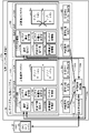
- FIG. 10 is a block diagram for explaining the anomaly handling processing of the virtualization system recovery device 10 of this embodiment.
- the abnormality detection for which the abnormality handling process is performed is any one of the abnormality detections 1 to 3 of the plurality of clusters.
- the distribution destination switching unit 21 is connected to a DNS (Domain Name System) 25 outside the recovery device 10 .
- the DNS 25 contains domains (or domain names) indicating the names of the applications 15a and 15b of the respective clusters 12A and 12B, and resolution destination IP (Internet Protocol) addresses corresponding to the addresses of the communication distribution units 14a of the respective clusters 12A and 12B.
- the DNS 25 converts between domains and IP addresses, and includes a DNS record table 25a.
- the DNS record table 25a stores domain names and resolution destination IP addresses in association with each other.
- "Svc1.net” as the domain name of the application 15a for each of the clusters 12A and 12B is added to "first cluster 12A' and 'the IP address of the second cluster 12B' are associated with each other.
- the DNS 25 When an external server (not shown) queries the DNS 25 having such a table 25a for the resolution destination IP address, the DNS 25 returns the IP addresses of both clusters 12A and 12B. Therefore, the external server can transmit data to both clusters 12A and 12B.
- the external anomaly detection unit 23 shown in FIG. 10 detects an anomaly in any one of the anomaly detections 1 to 3 of the plurality of clusters 12A and 12B (for example, an anomaly of the second cluster 12B).
- the external anomaly detection unit 23 notifies the allocation destination switching unit 21 of the anomaly detection of the second cluster 12B as indicated by an arrow Y34.
- the distribution destination switching unit 21 notifies the DNS 25 of an instruction to stop the communication distribution to the second cluster 12B (communication distribution stop instruction) as indicated by an arrow Y35.
- the DNS 25 resolves the second cluster 12B to the resolution destination IP address associated with both the domain names "Svc1.net” and "Svc2.net” in the table 25a shown in FIG. process to delete the IP address of
- step S1 shown in FIG. 13 a failure (x mark) occurs in the applications 15a and 15b of the second cluster 12B, and this abnormality is detected by the internal abnormality detection unit 17B.
- the internal abnormality detection section 17B notifies the external abnormality detection section 23 of the abnormality of the second cluster 12B as indicated by an arrow Y31b.
- step S2 the external anomaly detection unit 23 detects an anomaly in the second cluster 12B from the above notification, and notifies the allocation destination switching unit 21 as indicated by an arrow Y34.
- step S3 the distribution destination switching unit 21 notifies the DNS 25 of an instruction to stop communication distribution to the second cluster 12B, as indicated by an arrow Y35.
- step S4 the DNS 25 deletes the IP address of the second cluster 12B from the resolution destination IP addresses associated with both the domain names "Svc1.net” and "Svc2.net” in the table 25a shown in FIG. do.
- the resolution destination IP address associated with both of the domain names "Svc1.net” and “Svc2.net” in the table 25a is only the IP address of the first cluster 12A.
- step S5 when the external server inquires of the DNS 25 about the resolution destination IP address, the DNS 25 returns only the IP address of the first cluster 12A. In other words, access to the failed second cluster 12B becomes impossible, and communication to the second cluster 12B is stopped.
- the restoration device 10 includes a computational resource cluster 15, a cluster management unit 14, a plurality of clusters 12A and 12B, an internal anomaly detection unit 17, and an external anomaly detection unit 23.
- the computational resource cluster 15 is virtually created on a physical machine by container virtualization software, and clusters and arranges the virtually created containers.
- the cluster management unit 14 manages the placement and operation of virtually created and clustered containers.
- Each cluster 12A, 12B is configured with a computational resource cluster 15 and a cluster management unit 14.
- the internal anomaly detector 17 is arranged for each of the clusters 12A and 12B and is virtually created outside the virtually created computational resource cluster 15 and the cluster manager 14 to detect an anomaly of the container.
- the external anomaly detector 23 is virtually created outside each of the clusters 12A and 12B, and configured to detect an anomaly in the cluster in which the abnormal container is arranged when the internal anomaly detector 17 detects an anomaly in the container. .
- the external abnormality detection unit 23 detects that the cluster in which the abnormal container is arranged is abnormal. made it
- the internal anomaly detector 17 and the external anomaly detector 23 are not involved in container virtualization software that virtually creates the cluster manager 14 and the computational resource cluster 15 . Therefore, failures occurring in the respective clusters 12A and 12B can be detected earlier than the abnormality detection recovery function of the container virtualization software. This early detection of anomalies enables quick recovery of containers and the like related to cluster failures.
- the cluster management unit 14 is arranged in the signal input part of the cluster management unit 14, distributes the input signal to the subsequent stage and outputs it, and communicates to return a response when the cluster is normal according to the confirmation communication of the cluster.
- a distribution unit 14a is provided.
- the external anomaly detection unit 23 is configured to perform cluster confirmation communication to the communication distribution unit 14a at predetermined intervals, and to detect an anomaly in the cluster when no response is returned.
- the abnormality of each cluster can be detected without going through the internal abnormality detection unit 17 of each cluster 12A, 12B.
- the external anomaly detection unit 23 detects an anomaly in the cluster in which the container is placed when the internal anomaly detection unit 17 detects an anomaly in the container. , and when no response is returned, the abnormality is detected by both the process of detecting the abnormality of the cluster and the process of detecting it.
- anomaly detection of each cluster can be performed more appropriately.
- the DNS 25 that manages the domain name indicating the name of the application related to the container in association with the IP address of each cluster is provided outside the servers that constitute each cluster 12A and 12B.
- a distribution destination switching unit which is virtually created outside each cluster 12A, 12B and notifies the DNS 25 of a communication distribution stop instruction related to an abnormal cluster detected by the external abnormality detection unit 23, is provided for each cluster.
- the DNS 25 is configured to delete the IP address of the abnormal cluster indicated by the communication distribution stop instruction.
- the IP address of the cluster detected as abnormal by the external abnormality detection unit 23 is deleted from the cluster IP addresses managed by the DNS 25 . Therefore, when the external server queries the DNS 25 for the IP address of the cluster, it cannot access the IP address of the failed cluster. In other words, communication to the abnormal cluster can be stopped.
- the external abnormality detection unit 23, the allocation destination switching unit, and the DNS 25 are not involved in the container virtualization software described above. For this reason, a failure occurring in a cluster can be detected earlier than the failure detection and recovery function of the container virtualization software, so that the container or the like related to the failure of the cluster in which the failure has been detected can be quickly restored.
- FIG. 14 is a block diagram showing the configuration of a virtualization system restoration device 10A according to Modification 1 of the embodiment of the present invention.
- the communication distribution stop instruction indicated by the arrow Y35 from the distribution destination switching unit 21 is The reason for this is that the notification is also sent to the communication distribution units 14a of the clusters 12A and 12B.
- the communication distribution unit 14a stops the communication of the first cluster 12A or the second cluster 12B indicated by the notified communication distribution stop instruction. That is, since communication to each cluster 12A, 12B is always performed via the communication distribution unit 14a on the input side, the communication function of the communication distribution unit 14a is stopped in response to the communication distribution stop instruction. made it
- the communication distribution stop instruction for the abnormal cluster (for example, the second cluster 12B) can be sent to the communication distribution unit 14a of the abnormal cluster 12B, and the communication function of the communication distribution unit 14a can be stopped. .
- This stop makes it impossible to access the abnormal cluster 12B. Therefore, it is possible to omit the inquiry to the DNS 25 of the external server.
- FIG. 15 is a block diagram showing the configuration of a virtualization system recovery device 10B according to Modification 2 of this embodiment.
- the recovery device 10 differs from the recovery device 10 (FIG. 10) in that the first cluster 12A is equipped with an internal DNS 25A, the second cluster 12B is equipped with an internal DNS 25B, and the distribution destination switching is performed.
- the internal DNS 25A and 25B are also notified of the communication distribution stop instruction indicated by the arrow Y35 from the unit 21.
- the internal DNS 25A, 25B have a DNS record table 25a like the DNS 25, but the difference is that the table 25a is provided in cache memory. Therefore, in the internal DNS 25A, 25B, the information in the table 25a is deleted after a predetermined period of time. However, the internal DNS 25A, 25B can acquire necessary information from the DNS 25 as needed after the erasure.
- the internal anomaly detection unit 17A (or the internal anomaly detection unit 17B) responds to the communication distribution stop instruction (see arrow Y35) when the anomaly of the second cluster 12B is detected. A process of deleting the IP address of the cluster 12B is performed.
- the external server can query the internal DNS 25A, 25B of each cluster for the IP address of each cluster 12A, 12B, so the load on the external DNS 25 can be reduced.
- the computer 100 includes a CPU (Central Processing Unit) 101, a ROM (Read Only Memory) 102, a RAM (Random Access Memory) 103, a HDD (Hard Disk Drive) 104, an input/output I/F (Interface) 105, and a communication I/F 106. , and a media I/F 107 .
- CPU Central Processing Unit
- ROM Read Only Memory
- RAM Random Access Memory
- HDD Hard Disk Drive
- I/F Interface
- media I/F 107 media I/F
- the CPU 101 operates based on programs stored in the ROM 102 or HDD 104, and controls each functional unit.
- the ROM 102 stores a boot program executed by the CPU 101 when the computer 100 is started, a program related to the hardware of the computer 100, and the like.
- the CPU 101 controls an output device 111 such as a printer or display and an input device 110 such as a mouse or keyboard via the input/output I/F 105 .
- the CPU 101 acquires data from the input device 110 or outputs generated data to the output device 111 via the input/output I/F 105 .
- the HDD 104 stores programs executed by the CPU 101 and data used by the programs.
- Communication I/F 106 receives data from another device (not shown) via communication network 112 and outputs the data to CPU 101, and also transmits data generated by CPU 101 to another device via communication network 112. .
- the media I/F 107 reads programs or data stored in the recording medium 113 and outputs them to the CPU 101 via the RAM 103 .
- the CPU 101 loads a program related to target processing from the recording medium 113 onto the RAM 103 via the media I/F 107, and executes the loaded program.
- the recording medium 113 is an optical recording medium such as a DVD (Digital Versatile Disc) or a PD (Phase change rewritable Disk), a magneto-optical recording medium such as an MO (Magneto Optical disk), a magnetic recording medium, a conductor memory tape medium, a semiconductor memory, or the like. is.
- the CPU 101 of the computer 100 executes a program loaded on the RAM 103 to perform virtualization.
- the function of the system recovery device 10 is realized.
- Data in the RAM 103 is also stored in the HDD 104 .
- the CPU 101 reads a program related to target processing from the recording medium 113 and executes it.
- the CPU 101 may read a program related to target processing from another device via the communication network 112 .
- a computational resource cluster that is virtually created on a physical machine by container virtualization software and that clusters and arranges the virtually created containers, and the virtually created and clustered containers a plurality of clusters each configured to include the computing resource cluster and the cluster management unit; arranged for each of the plurality of clusters, and the an internal anomaly detection unit that is virtually created outside the virtually created computational resource cluster and the cluster management unit and detects an anomaly in the container; and the virtually created outside of the plurality of clusters,
- the virtualization system recovery device is characterized by comprising an external anomaly detection unit that detects an anomaly in a cluster in which the abnormal container is arranged when the internal anomaly detection unit detects an anomaly in the container.
- the external anomaly detection unit detects an anomaly in the cluster in which the abnormal container is located.
- the internal anomaly detector and the external anomaly detector do not participate in the container virtualization software that virtually creates the cluster manager and computational resource cluster. Therefore, failures that occur in multiple clusters can be detected more quickly than the failure detection and recovery function of container virtualization software. This early detection of anomalies enables quick recovery of containers and the like related to cluster failures.
- the cluster management unit is arranged in the signal input part of the cluster management unit, distributes the input signal to the subsequent stage and outputs it, and communicates to return a response when the cluster is normal according to the confirmation communication of the cluster.
- the above ( 1) is the virtualization system recovery device according to the above.
- an abnormality in each cluster can be detected without going through the internal abnormality detection units for each of the clusters.
- the external anomaly detection unit performs processing for detecting an anomaly in the cluster in which the container is placed when the internal anomaly detection unit detects an anomaly in the container, and performs cluster confirmation communication to the communication distribution unit at a predetermined cycle. and, if the response is not returned, the abnormality is detected by both the process of detecting the abnormality of the cluster.
- anomaly detection of each cluster can be performed more appropriately.
- a DNS Domain Name System
- IP Internet Protocol
- the IP addresses of clusters detected as abnormal by the external abnormality detection unit are deleted from the IP addresses of clusters managed by DNS. Therefore, when the external server queries the DNS for the IP address of the cluster, it cannot access the IP address of the failed cluster. In other words, communication to the abnormal cluster can be stopped.
- the external anomaly detection unit, allocation destination switching unit, and DNS are not involved in the container virtualization software described above. For this reason, a failure occurring in a cluster can be detected earlier than the failure detection and recovery function of the container virtualization software, so that the container or the like related to the failure of the cluster in which the failure has been detected can be quickly restored.
- the distribution destination switching unit notifies the communication distribution units in the plurality of clusters of a communication distribution stop instruction related to the abnormal cluster detected by the external abnormality detection unit, and the communication distribution unit , the virtualization system recovery device according to the above (4), characterized in that a process of stopping a communication function is performed when a communication distribution stop instruction relating to an abnormal cluster detected by the external abnormality detection unit is notified. .
- an internal DNS for managing a domain name indicating the name of an application related to the container and an IP address for each cluster in association with each other, similar to the DNS, is provided;
- the virtualization system recovery device according to (4) above, characterized in that the internal DNS is notified of a communication distribution stop instruction from the previous switching unit.
- the external server can query the internal DNS of each cluster for the IP address of the cluster, so the load on the external DNS can be reduced.
Landscapes
- Engineering & Computer Science (AREA)
- Theoretical Computer Science (AREA)
- Quality & Reliability (AREA)
- Physics & Mathematics (AREA)
- General Engineering & Computer Science (AREA)
- General Physics & Mathematics (AREA)
- Hardware Redundancy (AREA)
Priority Applications (2)
| Application Number | Priority Date | Filing Date | Title |
|---|---|---|---|
| JP2023531190A JP7632633B2 (ja) | 2021-06-29 | 2021-06-29 | 仮想化システム復旧装置及び仮想化システム復旧方法 |
| PCT/JP2021/024528 WO2023275984A1 (ja) | 2021-06-29 | 2021-06-29 | 仮想化システム復旧装置及び仮想化システム復旧方法 |
Applications Claiming Priority (1)
| Application Number | Priority Date | Filing Date | Title |
|---|---|---|---|
| PCT/JP2021/024528 WO2023275984A1 (ja) | 2021-06-29 | 2021-06-29 | 仮想化システム復旧装置及び仮想化システム復旧方法 |
Publications (1)
| Publication Number | Publication Date |
|---|---|
| WO2023275984A1 true WO2023275984A1 (ja) | 2023-01-05 |
Family
ID=84691607
Family Applications (1)
| Application Number | Title | Priority Date | Filing Date |
|---|---|---|---|
| PCT/JP2021/024528 Ceased WO2023275984A1 (ja) | 2021-06-29 | 2021-06-29 | 仮想化システム復旧装置及び仮想化システム復旧方法 |
Country Status (2)
| Country | Link |
|---|---|
| JP (1) | JP7632633B2 (https=) |
| WO (1) | WO2023275984A1 (https=) |
Citations (3)
| Publication number | Priority date | Publication date | Assignee | Title |
|---|---|---|---|---|
| CN111414229A (zh) * | 2020-03-09 | 2020-07-14 | 网宿科技股份有限公司 | 一种应用容器异常处理方法及装置 |
| WO2020184362A1 (ja) * | 2019-03-08 | 2020-09-17 | ラトナ株式会社 | コンテナオーケストレーション技術を利用したセンサ情報処理システム |
| JP2021027398A (ja) * | 2019-07-31 | 2021-02-22 | 日本電気株式会社 | コンテナデーモン、情報処理装置、コンテナ型仮想化システム、パケット振り分け方法及びプログラム |
-
2021
- 2021-06-29 WO PCT/JP2021/024528 patent/WO2023275984A1/ja not_active Ceased
- 2021-06-29 JP JP2023531190A patent/JP7632633B2/ja active Active
Patent Citations (3)
| Publication number | Priority date | Publication date | Assignee | Title |
|---|---|---|---|---|
| WO2020184362A1 (ja) * | 2019-03-08 | 2020-09-17 | ラトナ株式会社 | コンテナオーケストレーション技術を利用したセンサ情報処理システム |
| JP2021027398A (ja) * | 2019-07-31 | 2021-02-22 | 日本電気株式会社 | コンテナデーモン、情報処理装置、コンテナ型仮想化システム、パケット振り分け方法及びプログラム |
| CN111414229A (zh) * | 2020-03-09 | 2020-07-14 | 网宿科技股份有限公司 | 一种应用容器异常处理方法及装置 |
Also Published As
| Publication number | Publication date |
|---|---|
| JP7632633B2 (ja) | 2025-02-19 |
| JPWO2023275984A1 (https=) | 2023-01-05 |
Similar Documents
| Publication | Publication Date | Title |
|---|---|---|
| US8910172B2 (en) | Application resource switchover systems and methods | |
| US9405640B2 (en) | Flexible failover policies in high availability computing systems | |
| JP4349871B2 (ja) | ファイル共有装置及びファイル共有装置間のデータ移行方法 | |
| US10348577B2 (en) | Discovering and monitoring server clusters | |
| JP6141189B2 (ja) | ファイルシステムにおける透過的なフェイルオーバーの提供 | |
| US7321992B1 (en) | Reducing application downtime in a cluster using user-defined rules for proactive failover | |
| CN101938368A (zh) | 刀片服务器系统中的虚拟机管理器和虚拟机处理方法 | |
| US20230318991A1 (en) | Dynamic, distributed, and scalable single endpoint solution for a service in cloud platform | |
| JP2014522052A (ja) | ハードウェア故障の軽減 | |
| US8990608B1 (en) | Failover of applications between isolated user space instances on a single instance of an operating system | |
| JP7632632B2 (ja) | 仮想化システム障害分離装置及び仮想化システム障害分離方法 | |
| CN115878269A (zh) | 集群迁移方法、相关装置及存储介质 | |
| JP2018055481A (ja) | ログ監視装置、ログ監視方法及びログ監視プログラム | |
| JP5712714B2 (ja) | クラスタシステム、仮想マシンサーバ、仮想マシンのフェイルオーバ方法、仮想マシンのフェイルオーバプログラム | |
| JP7694659B2 (ja) | 仮想化システム障害分離装置及び仮想化システム障害分離方法 | |
| WO2023275984A1 (ja) | 仮想化システム復旧装置及び仮想化システム復旧方法 | |
| US8595349B1 (en) | Method and apparatus for passive process monitoring | |
| US8533331B1 (en) | Method and apparatus for preventing concurrency violation among resources | |
| JP7311335B2 (ja) | 分散型コンテナ監視システム及び分散型コンテナ監視方法 | |
| JP7044971B2 (ja) | クラスタシステム、オートスケールサーバ監視装置、オートスケールサーバ監視プログラムおよびオートスケールサーバ監視方法 | |
| US20240256363A1 (en) | Cluster, cluster management method, and cluster management program | |
| CN114500577A (zh) | 数据访问系统及数据访问方法 | |
| JP2024148281A (ja) | プログラム、情報処理方法およびクラスタシステム | |
| US20250307076A1 (en) | Fault detection based on device component identifiers | |
| WO2020250407A1 (ja) | 監視装置、冗長切替方法、冗長切替プログラム、および、ネットワークシステム |
Legal Events
| Date | Code | Title | Description |
|---|---|---|---|
| 121 | Ep: the epo has been informed by wipo that ep was designated in this application |
Ref document number: 21948293 Country of ref document: EP Kind code of ref document: A1 |
|
| WWE | Wipo information: entry into national phase |
Ref document number: 2023531190 Country of ref document: JP |
|
| NENP | Non-entry into the national phase |
Ref country code: DE |
|
| 122 | Ep: pct application non-entry in european phase |
Ref document number: 21948293 Country of ref document: EP Kind code of ref document: A1 |