WO2023248784A1 - セラミックス溶射粒子および遮熱コーティング層の形成方法 - Google Patents
セラミックス溶射粒子および遮熱コーティング層の形成方法 Download PDFInfo
- Publication number
- WO2023248784A1 WO2023248784A1 PCT/JP2023/020990 JP2023020990W WO2023248784A1 WO 2023248784 A1 WO2023248784 A1 WO 2023248784A1 JP 2023020990 W JP2023020990 W JP 2023020990W WO 2023248784 A1 WO2023248784 A1 WO 2023248784A1
- Authority
- WO
- WIPO (PCT)
- Prior art keywords
- ceramic
- mass
- spray particles
- barrier coating
- ceramic spray
- Prior art date
- Legal status (The legal status is an assumption and is not a legal conclusion. Google has not performed a legal analysis and makes no representation as to the accuracy of the status listed.)
- Ceased
Links
Images


Classifications
-
- C—CHEMISTRY; METALLURGY
- C23—COATING METALLIC MATERIAL; COATING MATERIAL WITH METALLIC MATERIAL; CHEMICAL SURFACE TREATMENT; DIFFUSION TREATMENT OF METALLIC MATERIAL; COATING BY VACUUM EVAPORATION, BY SPUTTERING, BY ION IMPLANTATION OR BY CHEMICAL VAPOUR DEPOSITION, IN GENERAL; INHIBITING CORROSION OF METALLIC MATERIAL OR INCRUSTATION IN GENERAL
- C23C—COATING METALLIC MATERIAL; COATING MATERIAL WITH METALLIC MATERIAL; SURFACE TREATMENT OF METALLIC MATERIAL BY DIFFUSION INTO THE SURFACE, BY CHEMICAL CONVERSION OR SUBSTITUTION; COATING BY VACUUM EVAPORATION, BY SPUTTERING, BY ION IMPLANTATION OR BY CHEMICAL VAPOUR DEPOSITION, IN GENERAL
- C23C4/00—Coating by spraying the coating material in the molten state, e.g. by flame, plasma or electric discharge
- C23C4/04—Coating by spraying the coating material in the molten state, e.g. by flame, plasma or electric discharge characterised by the coating material
- C23C4/10—Oxides, borides, carbides, nitrides or silicides; Mixtures thereof
- C23C4/11—Oxides
-
- C—CHEMISTRY; METALLURGY
- C04—CEMENTS; CONCRETE; ARTIFICIAL STONE; CERAMICS; REFRACTORIES
- C04B—LIME, MAGNESIA; SLAG; CEMENTS; COMPOSITIONS THEREOF, e.g. MORTARS, CONCRETE OR LIKE BUILDING MATERIALS; ARTIFICIAL STONE; CERAMICS; REFRACTORIES; TREATMENT OF NATURAL STONE
- C04B35/00—Shaped ceramic products characterised by their composition; Ceramics compositions; Processing powders of inorganic compounds preparatory to the manufacturing of ceramic products
- C04B35/01—Shaped ceramic products characterised by their composition; Ceramics compositions; Processing powders of inorganic compounds preparatory to the manufacturing of ceramic products based on oxide ceramics
- C04B35/48—Shaped ceramic products characterised by their composition; Ceramics compositions; Processing powders of inorganic compounds preparatory to the manufacturing of ceramic products based on oxide ceramics based on zirconium or hafnium oxides, zirconates, zircon or hafnates
-
- C—CHEMISTRY; METALLURGY
- C04—CEMENTS; CONCRETE; ARTIFICIAL STONE; CERAMICS; REFRACTORIES
- C04B—LIME, MAGNESIA; SLAG; CEMENTS; COMPOSITIONS THEREOF, e.g. MORTARS, CONCRETE OR LIKE BUILDING MATERIALS; ARTIFICIAL STONE; CERAMICS; REFRACTORIES; TREATMENT OF NATURAL STONE
- C04B35/00—Shaped ceramic products characterised by their composition; Ceramics compositions; Processing powders of inorganic compounds preparatory to the manufacturing of ceramic products
- C04B35/01—Shaped ceramic products characterised by their composition; Ceramics compositions; Processing powders of inorganic compounds preparatory to the manufacturing of ceramic products based on oxide ceramics
- C04B35/48—Shaped ceramic products characterised by their composition; Ceramics compositions; Processing powders of inorganic compounds preparatory to the manufacturing of ceramic products based on oxide ceramics based on zirconium or hafnium oxides, zirconates, zircon or hafnates
- C04B35/486—Fine ceramics
-
- C—CHEMISTRY; METALLURGY
- C23—COATING METALLIC MATERIAL; COATING MATERIAL WITH METALLIC MATERIAL; CHEMICAL SURFACE TREATMENT; DIFFUSION TREATMENT OF METALLIC MATERIAL; COATING BY VACUUM EVAPORATION, BY SPUTTERING, BY ION IMPLANTATION OR BY CHEMICAL VAPOUR DEPOSITION, IN GENERAL; INHIBITING CORROSION OF METALLIC MATERIAL OR INCRUSTATION IN GENERAL
- C23C—COATING METALLIC MATERIAL; COATING MATERIAL WITH METALLIC MATERIAL; SURFACE TREATMENT OF METALLIC MATERIAL BY DIFFUSION INTO THE SURFACE, BY CHEMICAL CONVERSION OR SUBSTITUTION; COATING BY VACUUM EVAPORATION, BY SPUTTERING, BY ION IMPLANTATION OR BY CHEMICAL VAPOUR DEPOSITION, IN GENERAL
- C23C28/00—Coating for obtaining at least two superposed coatings either by methods not provided for in a single one of groups C23C2/00 - C23C26/00 or by combinations of methods provided for in subclasses C23C and C25C or C25D
- C23C28/30—Coatings combining at least one metallic layer and at least one inorganic non-metallic layer
- C23C28/32—Coatings combining at least one metallic layer and at least one inorganic non-metallic layer including at least one pure metallic layer
- C23C28/321—Coatings combining at least one metallic layer and at least one inorganic non-metallic layer including at least one pure metallic layer with at least one metal alloy layer
- C23C28/3215—Coatings combining at least one metallic layer and at least one inorganic non-metallic layer including at least one pure metallic layer with at least one metal alloy layer at least one MCrAlX layer
-
- C—CHEMISTRY; METALLURGY
- C23—COATING METALLIC MATERIAL; COATING MATERIAL WITH METALLIC MATERIAL; CHEMICAL SURFACE TREATMENT; DIFFUSION TREATMENT OF METALLIC MATERIAL; COATING BY VACUUM EVAPORATION, BY SPUTTERING, BY ION IMPLANTATION OR BY CHEMICAL VAPOUR DEPOSITION, IN GENERAL; INHIBITING CORROSION OF METALLIC MATERIAL OR INCRUSTATION IN GENERAL
- C23C—COATING METALLIC MATERIAL; COATING MATERIAL WITH METALLIC MATERIAL; SURFACE TREATMENT OF METALLIC MATERIAL BY DIFFUSION INTO THE SURFACE, BY CHEMICAL CONVERSION OR SUBSTITUTION; COATING BY VACUUM EVAPORATION, BY SPUTTERING, BY ION IMPLANTATION OR BY CHEMICAL VAPOUR DEPOSITION, IN GENERAL
- C23C28/00—Coating for obtaining at least two superposed coatings either by methods not provided for in a single one of groups C23C2/00 - C23C26/00 or by combinations of methods provided for in subclasses C23C and C25C or C25D
- C23C28/30—Coatings combining at least one metallic layer and at least one inorganic non-metallic layer
- C23C28/34—Coatings combining at least one metallic layer and at least one inorganic non-metallic layer including at least one inorganic non-metallic material layer, e.g. metal carbide, nitride, boride, silicide layer and their mixtures, enamels, phosphates and sulphates
- C23C28/345—Coatings combining at least one metallic layer and at least one inorganic non-metallic layer including at least one inorganic non-metallic material layer, e.g. metal carbide, nitride, boride, silicide layer and their mixtures, enamels, phosphates and sulphates with at least one oxide layer
- C23C28/3455—Coatings combining at least one metallic layer and at least one inorganic non-metallic layer including at least one inorganic non-metallic material layer, e.g. metal carbide, nitride, boride, silicide layer and their mixtures, enamels, phosphates and sulphates with at least one oxide layer with a refractory ceramic layer, e.g. refractory metal oxide, ZrO2, rare earth oxides or a thermal barrier system comprising at least one refractory oxide layer
-
- C—CHEMISTRY; METALLURGY
- C23—COATING METALLIC MATERIAL; COATING MATERIAL WITH METALLIC MATERIAL; CHEMICAL SURFACE TREATMENT; DIFFUSION TREATMENT OF METALLIC MATERIAL; COATING BY VACUUM EVAPORATION, BY SPUTTERING, BY ION IMPLANTATION OR BY CHEMICAL VAPOUR DEPOSITION, IN GENERAL; INHIBITING CORROSION OF METALLIC MATERIAL OR INCRUSTATION IN GENERAL
- C23C—COATING METALLIC MATERIAL; COATING MATERIAL WITH METALLIC MATERIAL; SURFACE TREATMENT OF METALLIC MATERIAL BY DIFFUSION INTO THE SURFACE, BY CHEMICAL CONVERSION OR SUBSTITUTION; COATING BY VACUUM EVAPORATION, BY SPUTTERING, BY ION IMPLANTATION OR BY CHEMICAL VAPOUR DEPOSITION, IN GENERAL
- C23C4/00—Coating by spraying the coating material in the molten state, e.g. by flame, plasma or electric discharge
- C23C4/02—Pretreatment of the material to be coated, e.g. for coating on selected surface areas
-
- C—CHEMISTRY; METALLURGY
- C23—COATING METALLIC MATERIAL; COATING MATERIAL WITH METALLIC MATERIAL; CHEMICAL SURFACE TREATMENT; DIFFUSION TREATMENT OF METALLIC MATERIAL; COATING BY VACUUM EVAPORATION, BY SPUTTERING, BY ION IMPLANTATION OR BY CHEMICAL VAPOUR DEPOSITION, IN GENERAL; INHIBITING CORROSION OF METALLIC MATERIAL OR INCRUSTATION IN GENERAL
- C23C—COATING METALLIC MATERIAL; COATING MATERIAL WITH METALLIC MATERIAL; SURFACE TREATMENT OF METALLIC MATERIAL BY DIFFUSION INTO THE SURFACE, BY CHEMICAL CONVERSION OR SUBSTITUTION; COATING BY VACUUM EVAPORATION, BY SPUTTERING, BY ION IMPLANTATION OR BY CHEMICAL VAPOUR DEPOSITION, IN GENERAL
- C23C4/00—Coating by spraying the coating material in the molten state, e.g. by flame, plasma or electric discharge
- C23C4/12—Coating by spraying the coating material in the molten state, e.g. by flame, plasma or electric discharge characterised by the method of spraying
- C23C4/134—Plasma spraying
-
- C—CHEMISTRY; METALLURGY
- C04—CEMENTS; CONCRETE; ARTIFICIAL STONE; CERAMICS; REFRACTORIES
- C04B—LIME, MAGNESIA; SLAG; CEMENTS; COMPOSITIONS THEREOF, e.g. MORTARS, CONCRETE OR LIKE BUILDING MATERIALS; ARTIFICIAL STONE; CERAMICS; REFRACTORIES; TREATMENT OF NATURAL STONE
- C04B2235/00—Aspects relating to ceramic starting mixtures or sintered ceramic products
- C04B2235/02—Composition of constituents of the starting material or of secondary phases of the final product
- C04B2235/30—Constituents and secondary phases not being of a fibrous nature
- C04B2235/32—Metal oxides, mixed metal oxides, or oxide-forming salts thereof, e.g. carbonates, nitrates, (oxy)hydroxides, chlorides
- C04B2235/3224—Rare earth oxide or oxide forming salts thereof, e.g. scandium oxide
- C04B2235/3225—Yttrium oxide or oxide-forming salts thereof
-
- C—CHEMISTRY; METALLURGY
- C04—CEMENTS; CONCRETE; ARTIFICIAL STONE; CERAMICS; REFRACTORIES
- C04B—LIME, MAGNESIA; SLAG; CEMENTS; COMPOSITIONS THEREOF, e.g. MORTARS, CONCRETE OR LIKE BUILDING MATERIALS; ARTIFICIAL STONE; CERAMICS; REFRACTORIES; TREATMENT OF NATURAL STONE
- C04B2235/00—Aspects relating to ceramic starting mixtures or sintered ceramic products
- C04B2235/02—Composition of constituents of the starting material or of secondary phases of the final product
- C04B2235/30—Constituents and secondary phases not being of a fibrous nature
- C04B2235/32—Metal oxides, mixed metal oxides, or oxide-forming salts thereof, e.g. carbonates, nitrates, (oxy)hydroxides, chlorides
- C04B2235/3231—Refractory metal oxides, their mixed metal oxides, or oxide-forming salts thereof
- C04B2235/3244—Zirconium oxides, zirconates, hafnium oxides, hafnates, or oxide-forming salts thereof
- C04B2235/3246—Stabilised zirconias, e.g. YSZ or cerium stabilised zirconia
Definitions
- the present disclosure relates to a method of forming ceramic spray particles and a thermal barrier coating layer.
- a method for forming a thermal barrier coating layer according to the present disclosure includes a metal bonding layer forming step of forming a metal bonding layer on a base material, and spraying ceramic spray particles on the metal bonding layer to form a ceramic layer.
- the ceramic spray particles contain ZrO 2 and Yb 2 O 3 , and the standard deviation of the content of Yb 2 O 3 in the ceramic spray particles is 2% by mass. The content is 7.0% by mass or less.
- thermal barrier coating layer According to the ceramic spray particles and the method for forming a thermal barrier coating layer according to the present disclosure, it is possible to form a thermal barrier coating that has low thermal conductivity and excellent thermal cycle durability.
- FIG. 2 is a schematic cross-sectional view of a heat-resistant member of the present disclosure.
- 1 is a flowchart of a method for forming a thermal barrier coating layer of the present disclosure.
- 1 is a flowchart of a method for manufacturing ceramic spray particles of the present disclosure.
- FIG. 2 is a schematic cross-sectional view of a laser thermal cycle test device.
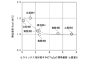
- FIG. 3 is a diagram showing the relationship between thermal conductivity and standard deviation of Yb 2 O 3 of ceramic spray particles.
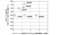
- FIG. 3 is a diagram showing the relationship between thermal cycle durability and standard deviation of Yb 2 O 3 of ceramic spray particles.
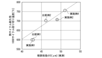
- FIG. 3 is a diagram showing the relationship between thermal cycle durability and integrated particle diameter d10 of ceramic spray particles.
- Metal bonding layer 22 Metallic bonding layer 22 is formed directly on substrate 21 .
- the metal bonding layer 22 reduces the difference in thermal expansion coefficient between the base material 21 and the ceramic layer 23, and alleviates thermal stress. This prevents the ceramic layer 23 from peeling off from the metal bonding layer 22. Further, the metal bonding layer 22 suppresses high-temperature oxidation and high-temperature corrosion of the base material 21. It is preferable to use a material with excellent corrosion resistance and oxidation resistance for the metal bonding layer 22.
- the metal bonding layer 22 is a MCrAlY alloy or the like. M in the MCrAlY alloy represents a metal element, and indicates, for example, a single metal element such as Ni, Co, or Fe, or two or more of these metal elements.
- the content of ZrO 2 is 75% by mass or more based on the total mass of the thermal barrier coating layer 20. A more preferable ZrO 2 content is 80% by mass or more. The content of ZrO 2 is 90% by mass or less. A more preferable ZrO 2 content is 84% by mass or less.
- the content of Yb 2 O 3 is preferably 10% by mass or more based on the total mass of the thermal barrier coating layer 20 .
- the content of Yb 2 O 3 is 10% by mass or more, the thermal cycle durability of the thermal barrier coating layer 20 is improved.
- a more preferable content of Yb 2 O 3 is 16% by mass or more. It is preferable that the content of Yb 2 O 3 is 25% by mass or less.
- the durability of the thermal barrier coating layer 20 may decrease.
- a more preferable content of Yb 2 O 3 is 20% by mass or less.
- the porosity is preferably 4% or more and 20% or less.
- the porosity of the ceramic layer 23 means the area ratio of pores in the ceramic layer 23.
- the porosity can be determined, for example, by randomly observing five fields of view (observation length about 3 mm) of the cross section of the ceramic layer 23 using an optical microscope (100x magnification) and using an image processing method.
- the thickness of the ceramic layer 23 is preferably 0.1 to 1.5 mm. If the thickness of the ceramic layer 23 is less than 0.1 mm, the heat shielding properties of the ceramic layer 23 may not be sufficient. If the thickness of the ceramic layer 23 exceeds 5 mm, the ceramic layer 23 may easily peel off, and the durability of the ceramic layer 23 may decrease.
- the heat-resistant member 10 has been described above. Since the ceramic layer 23 is made of ZrO 2 stabilized with Yb 2 O 3 , the crystal stability of the ceramic layer 23 is improved, and even when used in a high-temperature member such as a turbine, the ceramic layer 23 will remain stable during thermal cycles. The crystal phase of the material is difficult to change, and cracks caused by phase transformation and their propagation can be prevented.
- FIG. 2 is a flowchart of a method for forming the thermal barrier coating layer 20.
- the method for forming the thermal barrier coating layer 20 includes a metal bonding layer forming step S1 in which the metal bonding layer 22 is formed on the base material 21, and a thermal spraying of ceramic spray particles onto the metal bonding layer 22 after the metal bonding layer forming step S1.
- This includes a ceramic layer forming step S2 of forming the ceramic layer 23.
- Metal bonding layer forming step S1 In the metal bonding layer forming step S1, a metal bonding layer 22 is formed on the base material 21.
- the method of forming the metal bonding layer 22 is not particularly limited.
- the metal bonding layer 22 can be formed by low pressure plasma spraying, electron beam physical vapor deposition, or the like. Note that a base material 21 on which a metal bonding layer 22 is formed in advance may be prepared as a base material for thermal spraying.
- Ceramics layer forming step S2 In the ceramic layer forming step S2, a ceramic layer 23 is formed on the metal bonding layer 22.
- the ceramic layer 23 is formed by spraying ceramic spray particles onto the metal bonding layer 22 .
- the thermal spraying method is not particularly limited, but for example, a low-pressure plasma spraying method can be used.
- the ceramic spray particles of the present disclosure contain zirconium oxide (ZrO 2 ) and ytterbia (Yb 2 O 3 ).
- the content of ZrO 2 is 75% by mass or more based on the total mass of the ceramic spray particles.
- a more preferable ZrO 2 content is 80% by mass or more.
- the content of ZrO 2 is 90% by mass or less.
- a more preferable ZrO 2 content is 84% by mass or less.
- the standard deviation of the content of Yb 2 O 3 is 2% by mass or more and 7.0% by mass or less. If the standard deviation of the content of Yb 2 O 3 is less than 2% by mass, the thermal conductivity of the ceramic layer 23 will become high, which is not preferable. More preferably, the standard deviation of the content of Yb 2 O 3 is preferably 2.0% by mass or more based on the total mass of the ceramic spray particles. More preferably, the standard deviation of the content of Yb 2 O 3 is 2.3% by mass or more. The standard deviation of the content of Yb 2 O 3 is preferably 5.3% by mass or less. If the standard deviation of the Yb 2 O 3 content exceeds 7.0% by mass, it is not preferable because the thermal cycle durability decreases.
- the in-plane distribution of the chemical composition of ceramic spray particles can be analyzed using a known method. For example, ceramic spray particles are embedded in resin and cut. After cutting, the cross section is polished to prepare a specimen for observation. A cross section of the obtained material is analyzed at 10 random points using an electron probe microanalyzer.
- the Yb 2 O 3 content and the ZrO 2 content are calculated from the obtained Yb and Zr contents (atomic %).
- the average value of the obtained Yb 2 O 3 content is defined as the Yb 2 O 3 content.
- the average value of the ZrO 2 content is defined as the ZrO 2 content.
- the standard deviation of Yb 2 O 3 and the standard deviation of ZrO 2 are similarly evaluated.
- the cumulative particle diameter d10 of the ceramic spray particles is 40 ⁇ m or more. More preferably, the integrated particle diameter d10 of the ceramic spray particles is 45 ⁇ m or more. When the integrated particle diameter d10 of the ceramic spray particles is 40 ⁇ m or more, the porosity of the ceramic layer 23 is improved, and the thermal cycle durability of the ceramic layer 23 can be further improved.
- the integrated particle diameter d10 of the ceramic spray particles is preferably 100 ⁇ m or less. It is more preferable that the cumulative particle diameter d10 of the ceramic spray particles is 51 ⁇ m.
- the integrated particle diameter d10 can be measured based on JIS Z 8825:2013.
- the cumulative particle size d10 refers to the particle size below which 10% of the population falls. Note that the cumulative particle size d10 refers to a particle size that is cumulatively 10% from the small particle size side in the volume distribution curve.
- the maximum particle size of the ceramic spray particles is preferably 150 ⁇ m or less. By setting the maximum particle size of the ceramic spray particles to 150 ⁇ m or less, the ceramic spray particles can be melted easily in plasma spraying.
- the maximum particle size of the ceramic sprayed particles is the particle size expressed by the minimum opening of a metal mesh sieve through which all the ceramic sprayed particles pass.
- the ceramic spray particles of the present disclosure are preferably hollow inside.
- the porosity of the ceramic layer 23 is improved, and the heat shielding properties can be further improved.
- FIG. 3 is a flowchart of a method for producing ceramic spray particles.
- the method for producing ceramic spray particles of the present disclosure includes a mixing step S11 of mixing ZrO 2 powder, Yb 2 O 3 powder at a predetermined addition ratio, and water to produce a slurry, and a powder production process of producing a powder from the slurry.
- the process includes a forming step S12, a solid solution forming step S13 for converting the powder into a solid solution, and a classification step S14 for classifying the powder after solid solution forming.
- the ZrO 2 powder and Yb 2 O 3 powder are mixed in the proportions described above so that the standard deviation of the Yb 2 O 3 content in the ceramic spray particles is 2% by mass or more and 7.0% by mass or less. and water are mixed to produce a slurry. It is preferable to add a surfactant to the raw materials (ZrO 2 powder, Yb 2 O 3 powder, and water). By adding a surfactant, re-separation of the coagulated ZrO 2 powder and Yb 2 O 3 powder can be promoted.
- the weight ratio of ZrO 2 powder and Yb 2 O 3 powder to water is, for example, 1:1, although it is not particularly limited.
- water and a binder are added to the slurry before the powder forming step S12.
- the rotation speed during mixing of the raw materials is, for example, 10 to 30 rpm.
- the rotation speed can be adjusted as appropriate depending on the mixing device.
- classification step S14 In the classification step S14, the powder after solid solution formation is classified to obtain ceramic spray particles.
- the classification step S14 it is preferable to classify the particles into particles having a particle size of 150 ⁇ m or less. That is, it is preferable that the maximum particle size of the ceramic spray particles is 150 ⁇ m or less. When the particle size of ceramic spray particles exceeds 150 ⁇ m, they may not be melted well in plasma spray treatment. Further, in the classification step S14, it is preferable to remove small-sized ceramic spray particles so that the cumulative particle size d10 is 40 ⁇ m or more.
- the classification method is not particularly limited, and for example, a gyro shifter can be used.
- the method for producing ceramic spray particles of the present disclosure has been described above. According to the method for producing ceramic sprayed particles of the present disclosure, it is possible to produce ceramic sprayed particles that can form a thermal barrier coating that has low thermal conductivity and excellent thermal cycle durability.
- the conditions in the example are examples of conditions adopted to confirm the feasibility and effects of the present invention, and the present invention is based on this example of conditions. It is not limited.
- the present invention can adopt various conditions as long as the purpose of the present invention is achieved without departing from the gist of the present invention.
- Example 1 The mass ratio of ZrO 2 , Yb 2 O 3 , water, and surfactant was 84:16:100:1, and mixing was performed using a bead mill for 8 hours at a rotation speed of 18 rpm to prepare a slurry. and a binder were added at a mass ratio of 50:2.
- a powder was prepared from the slurry by spray drying, and the obtained powder was heated at 1450° C. for 10 hours in a heat treatment furnace. The obtained powder was classified (40 ⁇ m to 150 ⁇ m) to obtain ceramic spray particles of Example 1.
- the ceramic spray particles of Example 1 were embedded in resin and cut. When the cross section was observed, the ceramic sprayed particles of Example 1 were found to be hollow particles.
- the standard deviation of the concentration of Yb 2 O 3 with respect to the total mass of the ceramic spray particles of Example 1 was ⁇ 2.6% by mass, and the standard deviation of the concentration of Yb 2 O 3 with respect to the total mass of the ceramic spray particles of Example 1 was 10% of the ceramic spray particles of Example 1.
- the cumulative particle diameter d10 was 43 ⁇ m.
- Example 3 The mass ratio of ZrO 2 , Yb 2 O 3 , water, and surfactant was 84:16:100:1, and mixing was carried out using a bead mill for 8 hours at a rotation speed of 5 rpm to prepare a slurry. and a binder were added at a mass ratio of 50:2.
- a powder was prepared from the slurry by spray drying, and the obtained powder was heated in a heat treatment furnace at 1450° C. for 10 hours. The obtained powder was classified (40 ⁇ m to 150 ⁇ m) to obtain ceramic spray particles of Example 2.
- the ceramic spray particles of Example 3 were embedded in resin and cut. When the cross section was observed, the ceramic sprayed particles of Example 3 were found to be hollow particles.
- Comparative example 1 The mass ratio of ZrO 2 , Yb 2 O 3 , water, and surfactant was 84:16:100:1, and the mixing was performed using a bead mill for 15 hours at a rotation speed of 10 rpm to prepare a slurry. and a binder were added at a mass ratio of 50:2.
- a powder was prepared from the slurry by spray drying, and the obtained powder was heated in a heat treatment furnace at 1450° C. for 10 hours.
- the obtained powder was classified (40 ⁇ m to 150 ⁇ m) to obtain ceramic spray particles of Comparative Example 1.
- the ceramic spray particles of Comparative Example 1 were embedded in a resin and cut. When the cross section was observed, the ceramic sprayed particles of Comparative Example 1 were found to be hollow particles.
- the standard deviation of the concentration of Yb 2 O 3 with respect to the total mass of the ceramic spray particles of Comparative Example 1 was ⁇ 0.2% by mass
- the standard deviation of the concentration of Yb 2 O 3 with respect to the total mass of the ceramic spray particles of Comparative Example 1 was ⁇ 0.2% by mass.
- the cumulative particle diameter d10 was 43 ⁇ m.
- Comparative example 2 The mass ratio of ZrO 2 , Yb 2 O 3 , water, and surfactant was 84:16:100:1, and mixing was performed using a bead mill for 15 hours at a rotation speed of 25 rpm to prepare a slurry. and a binder were added at a mass ratio of 50:2.
- a powder was prepared from the slurry by spray drying, and the obtained powder was heated in a heat treatment furnace at 1450° C. for 10 hours.
- the obtained powder was classified (40 ⁇ m to 150 ⁇ m) to obtain ceramic spray particles of Comparative Example 2.
- the ceramic spray particles of Comparative Example 2 were embedded in resin and cut. When the cross section was observed, the ceramic sprayed particles of Comparative Example 2 were found to be hollow particles.
- the standard deviation of the concentration of Yb 2 O 3 with respect to the total mass of the ceramic spray particles of Comparative Example 3 was ⁇ 7.3% by mass, and the standard deviation of the concentration of Yb 2 O 3 with respect to the total mass of the ceramic spray particles of Comparative Example 3 was 10% of the ceramic spray particles of Comparative Example 3.
- the cumulative particle diameter d10 was 50 ⁇ m.
- the heating time was 3 minutes
- the cooling time was 3 minutes
- the maximum surface temperature was 900° C.
- various maximum surface heating temperatures were set to measure the number of thermal cycles until the ceramic layer peeled off.
- the highest temperature among the surface heating temperatures obtained after 1000 cycles was taken as the temperature after 1000 cycles. The higher the temperature after 1000 cycles, the higher the thermal cycle durability.
- FIG. 5 is a diagram showing the relationship between the thermal conductivity of the thermal barrier coating layer and the standard deviation of Yb 2 O 3 of ceramic sprayed particles.
- the horizontal axis of FIG. 5 represents the standard deviation ( ⁇ mass%) of Yb 2 O 3 in the ceramic spray particles, and the vertical axis represents the thermal conductivity (kcal/mh° C.).
- the standard deviation of Yb 2 O 3 in the ceramic spray particles was less than 2.0% (Comparative Example 1 and Comparative Example 2)
- thermal conductivity tended to increase. It is presumed that in Comparative Example 1 and Comparative Example 2, the longer stirring time resulted in uniform mixing of the materials and higher thermal conductivity.
- FIG. 7 is a diagram showing the relationship between the thermal cycle durability of the thermal barrier coating layer and the integrated particle diameter d10 of the ceramic spray particles.
- the horizontal axis in FIG. 7 represents the integrated particle diameter d10 ( ⁇ m) of the ceramic spray particles, and the vertical axis in FIG. 7 represents the cutting temperature (° C.) around 1000 cycles.
- the integrated particle diameter d10 of the ceramic spray particles became larger, the temperature at which the particles were cut after 1000 cycles became higher.
- the cumulative particle diameter d10 was 45 ⁇ m or more, a high thermal cycle durability of 700° C. was exhibited.
- the ceramic spray particles according to the first aspect of the present disclosure are ceramic spray particles containing ZrO 2 and Yb 2 O 3 , and the standard deviation of the content of Yb 2 O 3 is 2 mass. % or more and 7.0% by mass or less.
- thermal barrier coating that has low thermal conductivity and excellent thermal cycle durability.
- the ceramic spray particles according to the second aspect of the present disclosure are the ceramic spray particles of (1), and the content of Yb 2 O 3 is 16 mass % based on the total mass of the ceramic spray particles. % or more.
- the thermal cycle durability of the thermal barrier coating layer 20 is improved.
- the ceramic spray particles according to the third aspect of the present disclosure are the ceramic spray particles of (1) or (2), and have an integrated particle diameter d10 of 40 ⁇ m or more.
- the thermal cycle durability of the thermal barrier coating layer 20 is further improved.
- the ceramic spray particles according to the fourth aspect of the present disclosure are the ceramic spray particles of (3), and have the integrated particle diameter d10 of 45 ⁇ m or more.
- thermal barrier coating that has low thermal conductivity and excellent thermal cycle durability.
- a method for forming a thermal barrier coating layer according to a sixth aspect of the present disclosure is the method for forming a thermal barrier coating layer according to (5), wherein the Yb The content of 2 O 3 is 16% by mass or more.
- the thermal cycle durability of the thermal barrier coating layer 20 is further improved.
- a method for forming a thermal barrier coating layer according to a seventh aspect of the present disclosure is the method for forming a thermal barrier coating layer according to (5) or (6), wherein the cumulative particle diameter d10 of the ceramic spray particles is It is 40 ⁇ m or more.
- the thermal cycle durability of the thermal barrier coating layer 20 is further improved.
- a method for forming a thermal barrier coating layer according to an eighth aspect of the present disclosure is the method for forming a thermal barrier coating layer according to (7), in which the integrated particle diameter d10 is 45 ⁇ m or more.
- the thermal cycle durability of the thermal barrier coating layer 20 is further improved.
- thermal barrier coating layer of the present disclosure it is possible to form a thermal barrier coating that has low thermal conductivity and excellent thermal cycle durability.
Landscapes
- Chemical & Material Sciences (AREA)
- Engineering & Computer Science (AREA)
- Materials Engineering (AREA)
- Organic Chemistry (AREA)
- Physics & Mathematics (AREA)
- Plasma & Fusion (AREA)
- Mechanical Engineering (AREA)
- Metallurgy (AREA)
- Chemical Kinetics & Catalysis (AREA)
- Ceramic Engineering (AREA)
- Inorganic Chemistry (AREA)
- Manufacturing & Machinery (AREA)
- Structural Engineering (AREA)
- Composite Materials (AREA)
- Coating By Spraying Or Casting (AREA)
Abstract
Description
以下、本開示の遮熱コーティング層が形成された耐熱部材について説明する。図1は、本開示に係る耐熱部材10の模式断面図である。耐熱部材10は、基材21と、基材21上に形成された金属結合層22と、金属結合層22上に形成されたセラミックス層23と、を備える。遮熱コーティング層20は、金属結合層22とセラミックス層23とを備える。
基材21は、例えば、動翼などに用いられる高温用耐熱合金基材である。基材21の化学組成は、例えば、質量%で、Ni:20~40質量%、Cr:10~30質量%、Al:4~15質量%、Y0.1~5質量%、Re:0.5~10質量%を含み、残部がCoである。なお、本明細書中において、「~」を用いて表される数値範囲は、「~」の前後に記載される数値を下限値および上限値として含む範囲を意味する。「未満」、「超」と示す数値には、その値が数値範囲に含まれない。
金属結合層22は、基材21上に直接形成される。金属結合層22は、基材21とセラミックス層23との熱膨張係数差を小さくし、熱応力を緩和する。これによって、セラミックス層23が金属結合層22から剥離することを抑制する。また、金属結合層22は、基材21の高温酸化、高温腐食を抑制する。金属結合層22には、耐食性および耐酸化性に優れた材料を用いることが好ましい。金属結合層22は、MCrAlY合金などである。MCrAlY合金のMは、金属元素を表し、例えば、Ni、Co、Feなどの単独の金属元素またはこれらの金属元素のうち2種以上であることを示す。
セラミックス層23は、Yb2O3で部分安定化させたZrO2(以下、YbSZと称する)からなる。セラミックス層23は、Yb2O3およびZrO2以外の不純物を含有していてもよい。不純物は、例えば、原料に混入している成分、製造工程において混入する成分である。YbSZからなるセラミックス層23は、優れた結晶安定性を備えているため、相変態に起因する応力の発生も抑制することができる。
本開示の遮熱コーティング層20の形成方法について説明する。図2は、遮熱コーティング層20の形成方法のフローチャートである。遮熱コーティング層20の形成方法は、基材21上に金属結合層22を形成する金属結合層形成工程S1と、金属結合層形成工程S1工程後に、金属結合層22上にセラミックス溶射粒子を溶射することで、セラミックス層23を形成するセラミックス層形成工程S2と、を含む。
金属結合層形成工程S1では、基材21に金属結合層22を形成する。金属結合層22の形成方法は、特に限定されない。金属結合層22は、低圧プラズマ溶射法や、電子ビーム物理蒸着法等により形成することができる。なお、予め基材21に金属結合層22が形成されたものを溶射用の基材として準備してもよい。
セラミックス層形成工程S2では、金属結合層22上にセラミックス層23を形成する。セラミックス層23は、セラミックス溶射粒子を金属結合層22上に溶射することでセラミックス層23を形成する。溶射方法は、特に限定されないが、例えば、低圧プラズマ溶射法を用いることができる。
次に、セラミックス層形成工程S2で用いるセラミックス溶射粒子について説明する。本開示のセラミックス溶射粒子は、酸化ジルコニウム(ZrO2)とイッテルビア(Yb2O3)とを含有する。
次に、本開示のセラミックス溶射粒子の製造方法について説明する。図3は、セラミックス溶射粒子の製造方法のフローチャートである。本開示のセラミックス溶射粒子の製造方法は、ZrO2粉末と所定の添加割合のYb2O3粉末と、水と、を混合し、スラリーを製造する混合工程S11と、スラリーから粉末を製造する粉末形成工程S12と、粉末を固溶体化する固溶体化工程S13と、固溶体化後の粉末を分級する分級工程S14とを含む。
混合工程S11では、セラミックス溶射粒子において、Yb2O3の含有量の標準偏差が2質量%以上、7.0質量%以下となるように、上述した割合のZrO2粉末およびYb2O3粉末と、水と、を混合してスラリーを製造する。原料(ZrO2粉末、Yb2O3粉末、および水)に界面活性剤を添加することが好ましい。界面活性剤を添加することで、凝集していたZrO2粉末、Yb2O3粉末の再分離を促進することができる。ZrO2粉末およびYb2O3粉末と、水と、の重量比は、特に限定されないが、例えば1:1である。粉末形成工程S12の前にスラリーに、水およびバインダーを加えることが好ましい。
粉末形成工程S12では、混合工程S11で得たスラリーから粉末を製造する。具体的には、スラリーをスプレードライ(噴霧乾燥)することで粉末を製造する。スプレードライの方法は特に限定されない。例えば、スピンディスク方式の場合、ディスクを高速回転(10000rpm)させているので、スラリーは球形になりながら弾き飛ばされる。球形になったスラリーは高温の旋回空気(約200℃)により、乾燥しながら旋回する。このとき、スラリーは、乾燥空気中で外側から徐々に乾燥し、固化していく。スラリー中の原料粒子が粗いため、原料粒子の隙間から水分が蒸発する。これによって、内部が中空のセラミックス溶射粒子を得ることができる。
固溶体化工程S13では、粉末形成工程S12で得られた粉末を固溶体化する。具体的には、得られた粉末を熱処理炉で、1450℃で10時間加熱処理を行う。このときの温度は、熱処理炉の設定温度である。この熱処理によりZrO2とYb2O3とが、拡散・固溶体化し、溶射に適した強度を得ることができる。
分級工程S14では、固溶体化後の粉末を分級し、セラミックス溶射粒子を得る。分級工程S14では、粒径150μm以下に分級することが好ましい。即ち、セラミックス溶射粒子の最大粒径を150μm以下とすることが好ましい。セラミックス溶射粒子の粒径が150μm超の場合、プラズマ溶射処理において、良好に溶融しない場合がある。また、分級工程S14において、積算粒径d10が40μm以上となるように、小粒径のセラミックス溶射粒子を除去することが好ましい。分級の方法は特に限定されず、例えば、ジャイロシフターを用いることができる。
ZrO2とYb2O3と水と界面活性剤の質量比が84:16:100:1とし、ビーズミルを用い、混合時間を8時間、回転数18rpmで混合を行い、スラリーを作製し、水とバインダーを質量比で50:2の割合で添加した。スプレードライでスラリーから粉末を作製し、得られた粉末を熱処理炉で1450℃で10時間加熱した。得られた粉末を分級(40μm~150μm)し、実施例1のセラミックス溶射粒子を得た。実施例1のセラミックス溶射粒子を樹脂に埋め込み、切断した。その断面を観察したところ、実施例1のセラミックス溶射粒子は中空の粒子であった。後述の方法で測定したところ、実施例1のセラミックス溶射粒子の全質量に対するYb2O3の濃度の標準偏差は±2.6質量%であり、また、実施例1のセラミックス溶射粒子の10%積算粒径d10は43μmであった。
ZrO2とYb2O3と水と界面活性剤の質量比が84:16:100:1とし、ビーズミルを用い、混合時間を8時間、回転数25rpmで混合を行い、スラリーを作製し、水とバインダーを質量比で50:2の割合で添加した。スプレードライでスラリーから粉末を作製し、得られた粉末を熱処理炉で1450℃10時間加熱した。得られた粉末を分級し、実施例2のセラミックス溶射粒子を得た。実施例2のセラミックス溶射粒子を樹脂に埋め込み、切断した。その断面を観察したところ、実施例2のセラミックス溶射粒子は中空の粒子であった。後述の方法で測定したところ、実施例2のセラミックス溶射粒子の全質量に対するYb2O3の濃度の標準偏差は±2.3質量%であり、また、実施例2のセラミックス溶射粒子の10%積算粒径d10は49μmであった。
ZrO2とYb2O3と水と界面活性剤の質量比が84:16:100:1とし、ビーズミルを用い、混合時間を8時間、回転数5rpmで混合を行い、スラリーを作製し、水とバインダーを質量比で50:2の割合で添加した。スプレードライでスラリーから粉末を作製し、得られた粉末を熱処理炉で1450℃10時間加熱した。得られた粉末を分級(40μm~150μm)し、実施例2のセラミックス溶射粒子を得た。実施例3のセラミックス溶射粒子を樹脂に埋め込み、切断した。その断面を観察したところ、実施例3のセラミックス溶射粒子は中空の粒子であった。後述の方法で測定したところ、実施例3のセラミックス溶射粒子の全質量に対するYb2O3の濃度の標準偏差は±5.3質量%であり、また、実施例3のセラミックス溶射粒子の10%積算粒径d10は43μmであった。
ZrO2とYb2O3と水と界面活性剤の質量比が84:16:100:1とし、ビーズミルを用い、混合時間を10時間、回転数25rpmで混合を行い、スラリーを作製し、水とバインダーを質量比で50:2の割合で添加した。スプレードライでスラリーから粉末を作製し、得られた粉末を熱処理炉で1450℃10時間加熱した。得られた粉末を分級(40μm~150μm)し、実施例4のセラミックス溶射粒子を得た。実施例4のセラミックス溶射粒子を樹脂に埋め込み、切断した。その断面を観察したところ、実施例4のセラミックス溶射粒子は中空の粒子であった。後述の方法で測定したところ、実施例4のセラミックス溶射粒子の全質量に対するYb2O3の濃度の標準偏差は±2.5質量%であり、また、実施例4のセラミックス溶射粒子の10%積算粒径d10は51μmであった。
ZrO2とYb2O3と水と界面活性剤の質量比が84:16:100:1とし、ビーズミルを用い、混合時間を15時間、回転数10rpmで混合を行い、スラリーを作製し、水とバインダーを質量比で50:2の割合で添加した。スプレードライでスラリーから粉末を作製し、得られた粉末を熱処理炉で1450℃10時間加熱した。得られた粉末を分級(40μm~150μm)し、比較例1のセラミックス溶射粒子を得た。比較例1のセラミックス溶射粒子を樹脂に埋め込み、切断した。その断面を観察したところ、比較例1のセラミックス溶射粒子は中空の粒子であった。後述の方法で測定したところ、比較例1のセラミックス溶射粒子の全質量に対するYb2O3の濃度の標準偏差は±0.2質量%であり、また、比較例1のセラミックス溶射粒子の10%積算粒径d10は43μmであった。
ZrO2とYb2O3と水と界面活性剤の質量比が84:16:100:1とし、ビーズミルを用い、混合時間を15時間、回転数25rpmで混合を行い、スラリーを作製し、水とバインダーを質量比で50:2の割合で添加した。スプレードライでスラリーから粉末を作製し、得られた粉末を熱処理炉で1450℃10時間加熱した。得られた粉末を分級(40μm~150μm)し、比較例2のセラミックス溶射粒子を得た。比較例2のセラミックス溶射粒子を樹脂に埋め込み、切断した。その断面を観察したところ、比較例2のセラミックス溶射粒子は中空の粒子であった。後述の方法で測定したところ、比較例2のセラミックス溶射粒子の全質量に対するYb2O3の濃度の標準偏差は±1.2質量%であり、また、比較例2のセラミックス溶射粒子の10%積算粒径d10は46μmであった。
ZrO2とYb2O3と水と界面活性剤の質量比が84:16:100:1とし、ビーズミルを用い、混合時間を15時間、回転数25rpmで混合を行い、スラリーを作製し、水とバインダーを質量比で50:2の割合で添加した。スプレードライでスラリーから粉末を作製し、熱処理をせずに、粉末を分級(40μm~150μm)し、比較例3のセラミックス溶射粒子を得た。比較例3のセラミックス溶射粒子を樹脂に埋め込み、切断した。その断面を観察したところ、比較例3のセラミックス溶射粒子は中空の粒子であった。後述の方法で測定したところ、比較例3のセラミックス溶射粒子の全質量に対するYb2O3の濃度の標準偏差は±7.3質量%であり、また、比較例3のセラミックス溶射粒子の10%積算粒径d10は50μmであった。
試験片として、厚さ5mmの耐熱合金基材(商標名:IN-738LC)に、低圧プラズマ溶射法にて膜厚100μmの金属結合層(Ni:32質量%、Cr:21質量%、Al:8質量%、Y:0.5質量%、Co:残部)が形成されたものを用いた。上記で製造した実施例1~4および比較例1~3のセラミックス溶射粒子を用い金属結合層上に大気圧プラズマ溶射法により、セラミックス層(YbSZ層)を積層して遮熱コーティング層を形成した。尚、各試料において金属結合層(CoNiCrAlY)の厚さは0.1mm、セラミックス層(YbSZ)の厚さは0.5mmで共通とした。
実施例1~4および比較例1~3の各セラミックス溶射粒子について、Yb2O3の含有量の標準偏差を測定した。具体的には、以下の方法で測定した。得られたセラミックス溶射粒子を樹脂に埋め込み切断を行った。切断した後の断面を研磨し、研磨後の断面をエレクトロンプローブマイクロアナライザでランダムに10か所、点分析した。点分析で得られたYbおよびZrの各含有量(原子%)からYb2O3の含有量およびZrO2の含有量を計算し、標準偏差を求めた。
実施例1~4および比較例1~3の各セラミックス溶射粒子の粒度分布は、レーザ散乱回折式粒度分布測定装置(マイクロトラック社製)を用いて測定した。得られた粒度分布から実施例1~4および比較例1~3の各セラミックス溶射粒子の積算粒径d10を得た。なお、セラミックス溶射粒子の最大粒径はメッシュを用いて計測した。実施例1~4および比較例1~3のセラミックス溶射粒子の最大粒径は150μmであった。
実施例1~4および比較例1~3の遮熱コーティング層の熱伝導率をJIS R1611:2010で規定されるレーザフラッシュ法により測定した。
上記で得られた実施例1~4および比較例1~3のセラミックス溶射粒子を用いた遮熱コーティング層の熱サイクル耐久性の評価を行った。図4は、熱サイクル耐久性の評価に用いたレーザ式熱サイクル試験装置の模式断面図である。この図に示すレーザ式熱サイクル試験装置において、本体部33上に配設された試料ホルダ32に、基材21上に遮熱コーティング層20が形成された試料31を、遮熱コーティング層20が外側となるように配置した。試料31に対してCO2レーザ装置30からレーザ光Lを照射し、試料31を、遮熱コーティング層20側から加熱した。また、レーザ装置30による加熱と同時に本体部33を貫通して本体部33の内部の試料31裏面側と対向する位置に配設された冷却ガスノズル34の先端から吐出されるガス流Fにより試料31をその裏面側から冷却した。
上記の実施形態に記載のセラミックス溶射粒子および遮熱コーティング層の形成方法は以下のように把握され得る。
Claims (8)
- ZrO2とYb2O3とを含有するセラミックス溶射粒子であって、
前記Yb2O3の含有量の標準偏差が、2質量%以上、7.0質量%以下である、セラミックス溶射粒子。 - 前記セラミックス溶射粒子の全質量に対する質量%で、
前記Yb2O3の含有量が16質量%以上である、請求項1に記載のセラミックス溶射粒子。 - 積算粒径d10が40μm以上である、請求項1または2に記載のセラミックス溶射粒子。
- 前記積算粒径d10が45μm以上である、請求項3に記載のセラミックス溶射粒子。
- 基材上に金属結合層を形成する、金属結合層形成工程と、
前記金属結合層上にセラミックス溶射粒子を溶射して、セラミックス層を形成する、セラミックス層形成工程と、を含み、
前記セラミックス溶射粒子は、ZrO2とYb2O3とを含有し、
前記セラミックス溶射粒子中の前記Yb2O3の含有量の標準偏差が、2質量%以上、7.0質量%以下である、遮熱コーティング層の形成方法。 - 前記セラミックス溶射粒子の全質量に対する質量%で、
前記Yb2O3の含有量が16質量%以上である、請求項5に記載の遮熱コーティング層の形成方法。 - 前記セラミックス溶射粒子の積算粒径d10が40μm以上である、請求項5または6に記載の遮熱コーティング層の形成方法。
- 前記積算粒径d10が45μm以上である、請求項7に記載の遮熱コーティング層の形成方法。
Priority Applications (5)
| Application Number | Priority Date | Filing Date | Title |
|---|---|---|---|
| US18/833,039 US20250146117A1 (en) | 2022-06-23 | 2023-06-06 | Ceramic thermal spray particles and method for forming thermal barrier coating layer |
| DE112023002740.4T DE112023002740T5 (de) | 2022-06-23 | 2023-06-06 | Keramische thermische spritzpartikel und verfahren zum bilden von wärmedämmbeschichtungsschicht |
| CN202380018412.5A CN118591652A (zh) | 2022-06-23 | 2023-06-06 | 陶瓷喷涂粒子及热障涂层的形成方法 |
| KR1020247028729A KR20240144262A (ko) | 2022-06-23 | 2023-06-06 | 세라믹스 용사 입자 및 차열 코팅층의 형성 방법 |
| JP2024528744A JP7721003B2 (ja) | 2022-06-23 | 2023-06-06 | セラミックス溶射粒子および遮熱コーティング層の形成方法 |
Applications Claiming Priority (2)
| Application Number | Priority Date | Filing Date | Title |
|---|---|---|---|
| JP2022101154 | 2022-06-23 | ||
| JP2022-101154 | 2022-06-23 |
Publications (1)
| Publication Number | Publication Date |
|---|---|
| WO2023248784A1 true WO2023248784A1 (ja) | 2023-12-28 |
Family
ID=89379920
Family Applications (1)
| Application Number | Title | Priority Date | Filing Date |
|---|---|---|---|
| PCT/JP2023/020990 Ceased WO2023248784A1 (ja) | 2022-06-23 | 2023-06-06 | セラミックス溶射粒子および遮熱コーティング層の形成方法 |
Country Status (6)
| Country | Link |
|---|---|
| US (1) | US20250146117A1 (ja) |
| JP (1) | JP7721003B2 (ja) |
| KR (1) | KR20240144262A (ja) |
| CN (1) | CN118591652A (ja) |
| DE (1) | DE112023002740T5 (ja) |
| WO (1) | WO2023248784A1 (ja) |
Citations (3)
| Publication number | Priority date | Publication date | Assignee | Title |
|---|---|---|---|---|
| JP2010505717A (ja) * | 2006-05-26 | 2010-02-25 | プラクスエア・テクノロジー・インコーポレイテッド | 高純度粉末及びそれから調製される被膜 |
| JP2011214054A (ja) * | 2010-03-31 | 2011-10-27 | Mitsubishi Heavy Ind Ltd | 遮熱コーティング用溶射粉、遮熱コーティング、タービン部材及びガスタービン、並びに遮熱コーティング用溶射粉の製造方法 |
| CN108441806A (zh) * | 2018-04-11 | 2018-08-24 | 天津大学 | 一种热障涂层的制备方法及其热障涂层 |
Family Cites Families (3)
| Publication number | Priority date | Publication date | Assignee | Title |
|---|---|---|---|---|
| JP3372185B2 (ja) * | 1996-03-29 | 2003-01-27 | 株式会社東芝 | 耐熱部材 |
| JP5481239B2 (ja) | 2009-03-18 | 2014-04-23 | 東レ株式会社 | 薄膜付シートの製造装置及び薄膜付シートの製造方法、並びにこれらに用いられる円筒状ロール |
| CN106574356B (zh) | 2014-09-05 | 2019-07-23 | 三菱日立电力系统株式会社 | 热喷涂用粉末的制造方法、以及热喷涂用粉末 |
-
2023
- 2023-06-06 CN CN202380018412.5A patent/CN118591652A/zh active Pending
- 2023-06-06 WO PCT/JP2023/020990 patent/WO2023248784A1/ja not_active Ceased
- 2023-06-06 KR KR1020247028729A patent/KR20240144262A/ko active Pending
- 2023-06-06 JP JP2024528744A patent/JP7721003B2/ja active Active
- 2023-06-06 DE DE112023002740.4T patent/DE112023002740T5/de active Pending
- 2023-06-06 US US18/833,039 patent/US20250146117A1/en active Pending
Patent Citations (3)
| Publication number | Priority date | Publication date | Assignee | Title |
|---|---|---|---|---|
| JP2010505717A (ja) * | 2006-05-26 | 2010-02-25 | プラクスエア・テクノロジー・インコーポレイテッド | 高純度粉末及びそれから調製される被膜 |
| JP2011214054A (ja) * | 2010-03-31 | 2011-10-27 | Mitsubishi Heavy Ind Ltd | 遮熱コーティング用溶射粉、遮熱コーティング、タービン部材及びガスタービン、並びに遮熱コーティング用溶射粉の製造方法 |
| CN108441806A (zh) * | 2018-04-11 | 2018-08-24 | 天津大学 | 一种热障涂层的制备方法及其热障涂层 |
Also Published As
| Publication number | Publication date |
|---|---|
| US20250146117A1 (en) | 2025-05-08 |
| KR20240144262A (ko) | 2024-10-02 |
| JP7721003B2 (ja) | 2025-08-08 |
| CN118591652A (zh) | 2024-09-03 |
| JPWO2023248784A1 (ja) | 2023-12-28 |
| DE112023002740T5 (de) | 2025-04-03 |
Similar Documents
| Publication | Publication Date | Title |
|---|---|---|
| Morelli et al. | CMAS corrosion of YSZ thermal barrier coatings obtained by different thermal spray processes | |
| Wang et al. | Effect of spraying power on microstructure and property of nanostructured YSZ thermal barrier coatings | |
| Loghman-Estarki et al. | Life time of new SYSZ thermal barrier coatings produced by plasma spraying method under thermal shock test and high temperature treatment | |
| JP4463472B2 (ja) | 予め合金化された安定化ジルコニアパウダー及び改良された熱バリアコーティング | |
| JP5602156B2 (ja) | 遮熱コーティングの製造方法、該遮熱コーティングを備えるタービン部材及びガスタービン | |
| US20080167173A1 (en) | Thermal spray coating of porous nanostructured ceramic feedstock | |
| Nejati et al. | Microstructural analysis and thermal shock behavior of plasma sprayed ceria-stabilized zirconia thermal barrier coatings with micro and nano Al2O3 as a third layer | |
| Markocsan et al. | Low thermal conductivity coatings for gas turbine applications | |
| JP7329507B2 (ja) | 溶射用の酸化ジルコニウム粉末 | |
| AU2007314546A1 (en) | Coated articles | |
| Shi et al. | Improved thermal shock resistance of GYYZO-YSZ double ceramic layer TBCs induced by induction plasma spheroidization | |
| Aranke et al. | Microstructural evolution and sintering of suspension plasma-sprayed columnar thermal barrier coatings | |
| Tamaddon Masoule et al. | Thermal insulation and thermal shock behavior of conventional and nanostructured plasma-sprayed TBCs | |
| JPWO2016129521A1 (ja) | 遮熱コーティングの製造方法 | |
| Xue et al. | Preparation and sintering behavior of GdYb-YSZ nanostructured thermal barrier coating | |
| JP5285486B2 (ja) | 遮熱コーティング用材料、遮熱コーティング、タービン部材及びガスタービン | |
| Li et al. | Microstructure, thermal and mechanical properties, and thermal cycling behavior of high-entropy (Y0. 2Gd0. 2Er0. 2Yb0. 2Lu0. 2) 2Zr2O7/YSZ thermal barrier coatings | |
| JP7721003B2 (ja) | セラミックス溶射粒子および遮熱コーティング層の形成方法 | |
| JP2005163185A (ja) | ガスタービン、遮熱コーティング材、その製造方法及びタービン部材 | |
| Schulz et al. | High‐Temperature Aging of Eb‐Pvd Thermal Barrier Coatings | |
| Garcia et al. | Mullite and mullite/ZrO2-7wt.% Y2O3 powders for thermal spraying of environmental barrier coatings | |
| Jamali et al. | Comparison of thermal shock behavior of nano-7YSZ, 15YSZ and 5.5 SYSZ thermal barrier coatings produced by APS method | |
| JP2015096638A (ja) | 耐熱部材及びそれを用いたガスタービン部材並びに耐熱部材の製造方法 | |
| Wang et al. | Effects of Yb3+ and Ce4+ co-doping on mechanical integrity and high-temperature durability enhancement of YSZ thermal barrier coatings | |
| Zhou et al. | Microstructure analyses and thermophysical properties of nanostructured thermal barrier coatings |
Legal Events
| Date | Code | Title | Description |
|---|---|---|---|
| 121 | Ep: the epo has been informed by wipo that ep was designated in this application |
Ref document number: 23826971 Country of ref document: EP Kind code of ref document: A1 |
|
| ENP | Entry into the national phase |
Ref document number: 2024528744 Country of ref document: JP Kind code of ref document: A |
|
| WWE | Wipo information: entry into national phase |
Ref document number: 202380018412.5 Country of ref document: CN |
|
| WWE | Wipo information: entry into national phase |
Ref document number: 18833039 Country of ref document: US |
|
| ENP | Entry into the national phase |
Ref document number: 20247028729 Country of ref document: KR Kind code of ref document: A |
|
| WWE | Wipo information: entry into national phase |
Ref document number: 112023002740 Country of ref document: DE |
|
| WWP | Wipo information: published in national office |
Ref document number: 112023002740 Country of ref document: DE |
|
| WWP | Wipo information: published in national office |
Ref document number: 18833039 Country of ref document: US |
|
| 122 | Ep: pct application non-entry in european phase |
Ref document number: 23826971 Country of ref document: EP Kind code of ref document: A1 |