WO2023248592A1 - 自動運転システム、運転整理方法、および運転整理プログラム - Google Patents
自動運転システム、運転整理方法、および運転整理プログラム Download PDFInfo
- Publication number
- WO2023248592A1 WO2023248592A1 PCT/JP2023/015180 JP2023015180W WO2023248592A1 WO 2023248592 A1 WO2023248592 A1 WO 2023248592A1 JP 2023015180 W JP2023015180 W JP 2023015180W WO 2023248592 A1 WO2023248592 A1 WO 2023248592A1
- Authority
- WO
- WIPO (PCT)
- Prior art keywords
- area
- risk
- vehicle
- driving system
- information
- Prior art date
- Legal status (The legal status is an assumption and is not a legal conclusion. Google has not performed a legal analysis and makes no representation as to the accuracy of the status listed.)
- Ceased
Links
Images



Classifications
-
- B—PERFORMING OPERATIONS; TRANSPORTING
- B60—VEHICLES IN GENERAL
- B60W—CONJOINT CONTROL OF VEHICLE SUB-UNITS OF DIFFERENT TYPE OR DIFFERENT FUNCTION; CONTROL SYSTEMS SPECIALLY ADAPTED FOR HYBRID VEHICLES; ROAD VEHICLE DRIVE CONTROL SYSTEMS FOR PURPOSES NOT RELATED TO THE CONTROL OF A PARTICULAR SUB-UNIT
- B60W60/00—Drive control systems specially adapted for autonomous road vehicles
- B60W60/001—Planning or execution of driving tasks
- B60W60/0015—Planning or execution of driving tasks specially adapted for safety
-
- B—PERFORMING OPERATIONS; TRANSPORTING
- B60—VEHICLES IN GENERAL
- B60W—CONJOINT CONTROL OF VEHICLE SUB-UNITS OF DIFFERENT TYPE OR DIFFERENT FUNCTION; CONTROL SYSTEMS SPECIALLY ADAPTED FOR HYBRID VEHICLES; ROAD VEHICLE DRIVE CONTROL SYSTEMS FOR PURPOSES NOT RELATED TO THE CONTROL OF A PARTICULAR SUB-UNIT
- B60W30/00—Purposes of road vehicle drive control systems not related to the control of a particular sub-unit, e.g. of systems using conjoint control of vehicle sub-units
- B60W30/10—Path keeping
-
- B—PERFORMING OPERATIONS; TRANSPORTING
- B60—VEHICLES IN GENERAL
- B60W—CONJOINT CONTROL OF VEHICLE SUB-UNITS OF DIFFERENT TYPE OR DIFFERENT FUNCTION; CONTROL SYSTEMS SPECIALLY ADAPTED FOR HYBRID VEHICLES; ROAD VEHICLE DRIVE CONTROL SYSTEMS FOR PURPOSES NOT RELATED TO THE CONTROL OF A PARTICULAR SUB-UNIT
- B60W60/00—Drive control systems specially adapted for autonomous road vehicles
-
- G—PHYSICS
- G08—SIGNALLING
- G08G—TRAFFIC CONTROL SYSTEMS
- G08G1/00—Traffic control systems for road vehicles
-
- G—PHYSICS
- G08—SIGNALLING
- G08G—TRAFFIC CONTROL SYSTEMS
- G08G1/00—Traffic control systems for road vehicles
- G08G1/01—Detecting movement of traffic to be counted or controlled
- G08G1/04—Detecting movement of traffic to be counted or controlled using optical or ultrasonic detectors
-
- G—PHYSICS
- G08—SIGNALLING
- G08G—TRAFFIC CONTROL SYSTEMS
- G08G1/00—Traffic control systems for road vehicles
- G08G1/09—Arrangements for giving variable traffic instructions
-
- G—PHYSICS
- G08—SIGNALLING
- G08G—TRAFFIC CONTROL SYSTEMS
- G08G1/00—Traffic control systems for road vehicles
- G08G1/16—Anti-collision systems
-
- B—PERFORMING OPERATIONS; TRANSPORTING
- B60—VEHICLES IN GENERAL
- B60W—CONJOINT CONTROL OF VEHICLE SUB-UNITS OF DIFFERENT TYPE OR DIFFERENT FUNCTION; CONTROL SYSTEMS SPECIALLY ADAPTED FOR HYBRID VEHICLES; ROAD VEHICLE DRIVE CONTROL SYSTEMS FOR PURPOSES NOT RELATED TO THE CONTROL OF A PARTICULAR SUB-UNIT
- B60W2530/00—Input parameters relating to vehicle conditions or values, not covered by groups B60W2510/00 or B60W2520/00
-
- B—PERFORMING OPERATIONS; TRANSPORTING
- B60—VEHICLES IN GENERAL
- B60W—CONJOINT CONTROL OF VEHICLE SUB-UNITS OF DIFFERENT TYPE OR DIFFERENT FUNCTION; CONTROL SYSTEMS SPECIALLY ADAPTED FOR HYBRID VEHICLES; ROAD VEHICLE DRIVE CONTROL SYSTEMS FOR PURPOSES NOT RELATED TO THE CONTROL OF A PARTICULAR SUB-UNIT
- B60W2552/00—Input parameters relating to infrastructure
-
- B—PERFORMING OPERATIONS; TRANSPORTING
- B60—VEHICLES IN GENERAL
- B60W—CONJOINT CONTROL OF VEHICLE SUB-UNITS OF DIFFERENT TYPE OR DIFFERENT FUNCTION; CONTROL SYSTEMS SPECIALLY ADAPTED FOR HYBRID VEHICLES; ROAD VEHICLE DRIVE CONTROL SYSTEMS FOR PURPOSES NOT RELATED TO THE CONTROL OF A PARTICULAR SUB-UNIT
- B60W2720/00—Output or target parameters relating to overall vehicle dynamics
- B60W2720/24—Direction of travel
Definitions
- the present invention relates to an automatic driving system, a timetable rescheduling method, and a timetable rescheduling program.
- Infrastructure-cooperative automatic driving system that automatically drives vehicles in the field using infrastructure information detected by infrastructure sensors installed on the field.
- Infrastructure-cooperative autonomous driving systems differ from control methods that use sensors on a single vehicle (on-vehicle sensors).By installing infrastructure sensors in the field, infrastructure-cooperative autonomous driving systems prevent the on-board sensors from jumping out of blind spots, etc. It is possible to ensure safety against accidental factors that are difficult to avoid.
- Field information from infrastructure sensors allows automated driving systems to grasp object information (danger information) regarding many areas that they control/manage.
- the dangerous state based on the acquired information differs depending on the type of risk that constitutes the dangerous state. For example, when a dangerous situation occurs due to the occurrence of an accident, the danger potential in the surrounding area increases due to accident response. Therefore, it is necessary to set a wide area as a dangerous area (also referred to as a risk area) depending on the dangerous situation. In addition, if the risk value of a specific area decreases in the set wide-area dangerous area, from the viewpoint of productivity, it is necessary to partially cancel the dangerous area setting of the area where the risk value has decreased.
- Patent Document 1 is a known technology regarding vehicle control/operation management that takes such area risks into consideration.
- Patent Document 1 states that, ⁇ When processing a zone where dangerous situations occur frequently, the frequency of occurrence increases even though it is the first sudden braking event, and it is mistakenly recognized as a zone where dangerous situations occur frequently.'' The method of solving this problem is described as follows: ⁇ From the vehicle driving information, the first time and first place where the dangerous situation occurred in the first vehicle, and the first time when the dangerous situation occurred in the second vehicle. 2, the extracted first time and second time are within a predetermined time width, and the first and second occurrence locations are When it is detected that the vehicle is within a predetermined distance range, a process is executed in which the occurrence of the dangerous state of the first vehicle and the occurrence of the dangerous state of the second vehicle are integrated and counted as the occurrence of one dangerous state. It is stated that the
- Patent Document 1 prevents the expansion of the dangerous area by integrating the number of safety controls during dangerous situations such as sudden braking. may be missed.
- the present invention has been made in view of the above circumstances, and its purpose is to provide an automatic driving system, a traffic rescheduling method, and a driving rescheduling method that can accurately set risk areas and realize safe automatic driving.
- the purpose is to provide a sorting program.
- an automatic driving system includes a business information database that records business information related to business plans or business changes in the field area, and an infrastructure that records infrastructure information from infrastructure sensors in the field area.
- a risk type is identified from the planning or operational site information recorded in the information database, the business information database, and the infrastructure information database, and a predetermined area of the site area is set as a risk area based on the risk type.
- a risk area setting section; and a vehicle route setting section that sets a travel route for the vehicle based on vehicle position information of a vehicle traveling within the site area and the risk area set by the risk area setting section. It is characterized by
- the operation reorganization method includes a work information recording step of recording work information regarding work plans or work changes within the field area, and an infrastructure information recording step of recording infrastructure information from infrastructure sensors within the field area. , identifying a risk type from the planned or operational site information recorded in the business information recording step and the infrastructure information recording step, and setting a predetermined area of the site area as a risk area based on the risk type; an area setting step; and a vehicle route setting step of setting a travel route for the vehicle based on vehicle position information of a vehicle traveling within the site area and the risk area set in the risk area setting step. It is characterized by
- the operation rescheduling program includes a work information recording procedure for recording work information regarding work plans or work changes in the field area, and an infrastructure information recording procedure for recording infrastructure information from infrastructure sensors in the field area.
- a risk type is identified from the planned or operational site information recorded in the business information recording procedure and the infrastructure information recording procedure, and a predetermined area of the site area is set as a risk area based on the risk type.
- the risk type is specified from the site information and the risk area is set from the site area, it is possible to accurately set the risk area and realize safe automatic driving.
- FIG. 1 is a schematic configuration diagram of an automatic driving system according to an embodiment of the present invention.
- 1 is a configuration diagram of an automatic driving system according to an embodiment of the present invention.
- It is an explanatory diagram of risk type DB.
- It is an explanatory diagram of a risk area range DB.
- It is an explanatory diagram of area risk value list DB.
- FIG. 7 is an explanatory diagram of an operational example of risk area setting by the risk area setting unit.
- FIG. 6 is an explanatory diagram of an operation example of risk area cancellation (resetting) by the risk area setting unit.
- FIG. 3 is an explanatory diagram of an example of the operation of a risk area setting section and a vehicle route setting section (risk area due to occurrence of an accident).
- FIG. 3 is an explanatory diagram of an example of the operation of a risk area setting unit and a vehicle route setting unit (risk areas due to sensor blind spots and equipment failures);
- FIG. 3 is an explanatory diagram of an example of the operation of a risk area setting unit and a vehicle route setting unit (risk area due to people or manned vehicles);
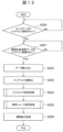
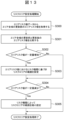
- FIG. 3 is an explanatory diagram of a display example of a display screen of an information display section. It is a flowchart of the main routine of a control device. It is a flowchart of the subroutine (risk area setting process) of a control device.
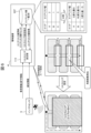
- FIG. 1 is a schematic configuration diagram of an automatic driving system 1 according to an embodiment of the present invention.
- the automatic driving system 1 includes a vehicle (automatic driving vehicle) 2, an infrastructure sensor 3, and a control device 4.
- the vehicle (automatic driving vehicle) 2 receives travel route information from the control device 4 and performs automatic driving within the site area, which is the driving area.
- the vehicle (self-driving vehicle) 2 may automatically drive within the field area using information acquired by a sensor mounted on the vehicle 2, map information, etc. under a predetermined situation. Further, the vehicle (self-driving vehicle) 2 may output vehicle position information detected using information acquired by a sensor mounted on the vehicle 2, map information, etc. to the control device 4.
- the infrastructure sensor (also referred to as a field sensor or the like) 3 is a sensor for detecting an object (target object) in the field area.
- the infrastructure sensor 3 includes, for example, a camera, LiDAR, radar, etc. installed on the site area.
- the infrastructure sensor 3 outputs detection information of objects within the field area (hereinafter also referred to as infrastructure information) to the control device 4.
- the infrastructure sensor 3 may detect the vehicle 2 traveling within the field area and output the vehicle position information to the control device 4.
- the control device 4 sets a driving route for the vehicle 2 within the site area based on the detection information (infrastructure information) of the infrastructure sensor 3, etc., and transmits the set driving route to the vehicle 2 by wireless communication.
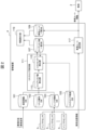
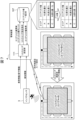
- FIG. 2 is a configuration diagram of the automatic driving system 1 according to an embodiment of the present invention, and particularly shows the internal configuration of the control device 4.
- the control device 4 of the automatic driving system 1 has, as a storage unit, a business information database (DB) 101, a risk type database (DB) 102, an infrastructure information database (DB) 103, a risk area range database (DB) 105, and an area risk value. It includes a list database (DB) 107 and a vehicle route list database (DB) 109, and includes a risk area setting section 111, a vehicle route setting section (also referred to as a reroute setting section) 117, and an information display section 119 as functional sections.
- the risk area setting section 111 includes an area risk value calculation section 113 and a risk area detection section 115.
- the business information DB 101 stores (records) business information related to business plans or business changes input or transmitted from system operators.
- the business information here includes planned site information such as road and equipment maintenance information within the site area.
- the infrastructure information DB 103 stores (records) detection information (infrastructure information) by the infrastructure sensor 3.
- the infrastructure information here includes operational site information such as information on the presence or absence of people and vehicles (manned vehicles, self-driving vehicles, etc.) in the site area, information on sensor blind spots, and the like.
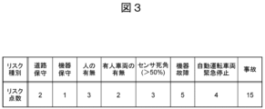
- the risk type DB 102 stores (records) information on risk scores (risk values) for each risk type. As shown in FIG. 3, in the risk type DB 102, risk values are managed separately for each risk type.
- the risk area range DB 105 stores (records) a risk area range setting table that sets the range of the risk area based on the risk type and area risk value, as described later.
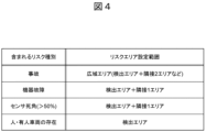
- the risk area range setting table is a table that defines the relationship between risk types included in detection areas, which will be described later, and risk area setting ranges.
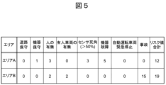
- the area risk value list DB 107 includes area risk values (total risk values) calculated for each predetermined area set in advance in the field area, and risk areas set based on the area risk value and risk type. (Details will be explained later).
- the vehicle route list DB 109 stores (records) information on travel routes (vehicle routes) for each vehicle 2 that are set based on risk areas, as described later.
- the area risk value calculation unit 113 of the risk area setting unit 111 calculates the risk type from the business information regarding the business plan or business change stored in the business information DB 101 or the detection information (infrastructure information) of the infrastructure sensor 3 stored in the infrastructure information DB 103. and calculates the area risk value for the entire area managed by the system (in other words, the detection area of the infrastructure sensor 3).
- the area risk value calculation unit 113 calculates an area risk value for each predetermined area within the field area based on the identified risk type.
- the area risk value calculation unit 113 refers to the risk type DB 102 (FIG. 3) and determines the area risk value based on the total value of the risk values of the identified risk types for each of the predetermined areas.
- the area risk value calculated for each predetermined area is stored in the area risk value list DB 107 (FIG. 5) together with the risk types that constitute the area risk value.
- the risk area detection unit 115 of the risk area setting unit 111 compares the previously calculated area risk value (last time or at a certain point in time) with the current area risk value, and if a certain amount of change occurs, the area risk value is changed.
- a risk area is set based on the risk types that make up the area (in other words, in combination with the risk types that make up the area risk value). Combinations with risk types include combinations where accidents have occurred, combinations where people or manned vehicles are present, combinations where sensor blind spots exist, and combinations where equipment failures exist (see also Figure 4). .
- the risk area detection unit 115 compares the previously calculated area risk value (last time or at a certain point) with the current area risk value, and detects a predetermined area where the amount of increase in the area risk value exceeds a predetermined amount of change. Specify as an area.
- the risk area detection unit 115 checks the risk area range setting table (FIG. 4) in the risk area range DB 105, and if the risk type that constitutes the area risk value of the detection area matches the risk type in the risk area range setting table, A risk area is set based on the risk area setting range of the risk area range setting table. In the example shown in FIG. 4, when "accident” is included as the risk type of the detection area, a wide area (detection area + two adjacent areas, etc.) is set as the risk area. Furthermore, if the risk types of the detection area include "equipment failure" or "sensor blind spot", the detection area + one adjacent area is set as the risk area. Furthermore, if the risk type of the detection area includes "person” or "manned vehicle”, only the detection area is set as a risk area.
- FOG. 4 risk area range setting table
- FIG. 6 shows an operational example of risk area setting by the risk area setting unit 111.
- a certain amount of change has occurred in area B (the amount of increase in the area risk value exceeds the predetermined amount of change). Since the risk types of area B include "equipment failure" and "sensor blind spot," area B and areas A and C adjacent to area B are set as risk areas.
- the risk area setting unit 111 (the risk area detection unit 115 of the risk area detection unit 115) focuses on the amount of change in the area risk value for the area set as the risk area, and when the area risk value has decreased by a certain amount, ( In other words, if the amount of decrease in the area risk value of a predetermined area set as a risk area exceeds a predetermined amount of change), risk area (re)setting is performed to remove that area from the risk area.
- FIG. 7 shows an example of the operation of the risk area setting unit 111 to cancel (reset) the risk area.
- a certain amount of change has occurred in area C (the amount of decrease in the area risk value exceeds a predetermined amount of change). Then, area C is removed from the risk area and the risk area is (re)set.
- the vehicle route setting unit 117 resets the travel route of the vehicle 2 traveling within the site area based on the vehicle position information of the vehicle 2 traveling within the site area and the risk area information extracted from the area risk value list DB 107 ( reroute).
- vehicle position information may be detected based on the detection information (infrastructure information) of the infrastructure sensor 3, or may be detected using information acquired by a sensor mounted on the vehicle 2, map information, etc. good.
- the vehicle route setting unit 117 routes vehicles existing within the risk area, vehicles existing outside the risk area, and vehicles planned to proceed from outside the risk area into the risk area based on different conditions. Set the route. In other words, the vehicle route setting unit 117 changes the traveling route of the vehicle 2 when traveling inside or outside the risk area, or when traveling from outside the risk area into the risk area.
- the risk area setting range differs depending on the type of risk in the area (risk area setting unit 111), and the reroute setting method for vehicles 2 existing inside and outside the risk area differs (vehicle route setting unit 117).
- vehicle route setting unit 117 A specific example of the reroute setting method of the vehicle route setting section 117 will be explained together with the risk area setting method of the risk area setting section 111 for each type of risk (risk type) using FIGS. 8 to 10.
- the risk area setting unit 111 sets a wide area (for example, detection area + 2 adjacent areas, all areas used for vehicle travel for accident processing) including the accident occurrence location (detection area) as a risk area (Fig. (See the risk area range setting table of the risk area range DB 105 in No. 4).
- the vehicle route setting unit 117 sets a reroute for the automated driving vehicle existing inside the risk area to promptly exit the wide risk area (see the left diagram in FIG. 8).
- the vehicle route setting unit 117 sets a reroute for an automated driving vehicle that exists outside the risk area so that it does not enter the wide risk area (see the right diagram in FIG. 8).
- the risk area setting unit 111 sets the surrounding area (for example, detection area + 1 adjacent area) including the dangerous event occurrence point (detection area) as a risk area (risk area range setting in the risk area range DB 105 in FIG. 4). (see table).
- the vehicle route setting unit 117 sets a reroute for the automated driving vehicle existing inside the risk area so that it does not travel through the dangerous event occurrence area (see the left diagram in FIG. 9).
- the vehicle route setting unit 117 sets a reroute for an automated driving vehicle that exists outside the risk area so that it does not enter the risk area (see the right diagram in FIG. 9).
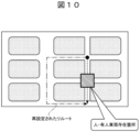
- the risk area setting unit 111 sets only the dangerous event occurrence location (detection area) as a risk area (see the risk area range setting table of the risk area range DB 105 in FIG. 4).
- the vehicle route setting unit 117 sets a reroute in which the automatically-driving vehicle does not travel in the risk area, regardless of whether it is inside or outside the risk area (see FIG. 10).
- Information on the driving route set by the vehicle route setting unit 117 is transmitted to the vehicle 2 by wireless communication.
- the vehicle 2 can automatically drive (automatically drive) within the site area based on the travel route transmitted from the vehicle route setting unit 117.
- information on the driving route set by the vehicle route setting unit 117 is stored in the vehicle route list DB 109.
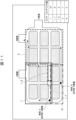
- the information display unit 119 displays the area risk for each area in the field area from the information stored in the area risk value list DB 107 and the vehicle route list DB 109 on the display screen on the desk of the system operator. Displays the value, set risk area, set driving route of each vehicle, etc.
- the system operator can, for example, grasp risk areas and modify the driving route of each vehicle.
- step S200 of FIG. 12 it is determined whether the sensor data has been registered in the system, and if the sensor data has been registered in the system, the process advances to step S201.
- step S201 it is determined whether the business plan and business change data have been registered in the system, and if the business plan and business change data have been registered in the system, the process advances to step S202.
- step S202 the data registered in steps S200 and S201 is read.
- step S203 the area risk value calculation unit 113 of the risk area setting unit 111 calculates the area risk value for each area within the site area.
- step S204 the risk area detection unit 115 of the risk area setting unit 111 executes risk area setting processing.
- step S205 the vehicle route setting unit 117 executes a vehicle reroute setting process based on the risk area set in step S204.
- step S206 the information display unit 119 displays the area risk value calculated in step S203, the risk area set in step S204, the driving route (reroute) set in S205, etc.
- step S300 of FIG. 13 the area risk value before update of the entire area is obtained from the area risk value data.
- step S301 the area risk values before and after the update for the entire area are compared.
- step S302 it is determined whether or not the area risk value has increased by a certain amount before and after the update (whether the amount of increase in the area risk value exceeds a predetermined amount of change). If it has increased by a certain amount, the process proceeds to step S303, where the range of the risk area is set based on the risk type in the area risk value (FIGS. 4 and 6), and the process proceeds to step S304. If the amount has not increased by a certain amount, step S303 is skipped and the process proceeds to step S304.
- step S304 it is determined whether the area risk value has decreased by a certain amount between before and after the update (whether the amount of decrease in the area risk value of a predetermined area set as a risk area exceeds a predetermined amount of change). If the amount has decreased by a certain amount, the process advances to step S305, and the range of the risk area is set to be reduced depending on the risk type (FIGS. 4 and 7). If the amount has not decreased by a certain amount, step S305 is skipped and the risk area setting process is ended.
- the automatic driving system 1 of the present embodiment includes a business information database 101 that records business information related to business plans or business changes in the field area, and infrastructure information recorded by the infrastructure sensor 3 in the field area.
- a risk type is identified from the infrastructure information database 103 to be used, and the planned or operational site information recorded in the business information database 101 and the infrastructure information database 103, and a predetermined area of the site area is designated based on the risk type.
- a driving route of the vehicle 2 is set based on a risk area setting unit 111 that is set as a risk area, vehicle position information of the vehicle 2 traveling within the site area, and the risk area set by the risk area setting unit 111.
- a vehicle route setting section 117 is provided.
- the risk area setting unit 111 calculates an area risk value based on the risk type for each predetermined area in the site area, and sets the predetermined area specified based on the risk type and the area risk value as the risk area. .
- the risk area setting unit 111 specifies a predetermined area in which the amount of increase in the area risk value exceeds a predetermined amount of change as a detection area, and specifies the risk type that constitutes the detection area and the area risk value of the detection area.
- a predetermined area identified based on the risk type (in combination with the risk type) is set as the risk area.
- the risk area setting unit 111 has a risk area range database 105 that records a risk area range setting table that sets the range of the risk area based on the risk type and the area risk value, and The range of the risk area is set based on the recorded risk area range setting table.
- the risk area setting unit 111 resets the risk area when the amount of decrease in the area risk value of the predetermined area set as the risk area exceeds a predetermined amount of change.
- the risk area setting unit 111 (partially) releases the predetermined area from the risk area.
- the automatic driving system 1 of the present embodiment identifies risk types from planned or operational site information, and calculates area risk values based on the risk types within the site area (area risk value calculation unit 113). , detects or sets a risk area based on the risk type and area risk value (risk area detection unit 115), and sets a vehicle travel route based on the risk area (vehicle route setting unit 117).
- the risk type is specified from the site information and the risk area is set from the site area, so the risk area can be accurately set and safe automatic driving can be achieved.
- each of the above-mentioned configurations, functions, processing units, processing means, etc. may be partially or entirely realized by hardware, for example, by designing an integrated circuit.
- each of the above configurations, functions, etc. may be realized by software by a processor interpreting and executing a program for realizing each function.
- Information such as programs, tables, files, etc. that realize each function can be stored in a memory, a storage device such as a hard disk, an SSD (Solid State Drive), or a recording medium such as an IC card, SD card, or DVD.
- control lines and information lines are shown that are considered necessary for explanation, and not all control lines and information lines are necessarily shown in the product. In reality, almost all components may be considered to be interconnected.
Landscapes
- Engineering & Computer Science (AREA)
- Automation & Control Theory (AREA)
- Transportation (AREA)
- Mechanical Engineering (AREA)
- Physics & Mathematics (AREA)
- General Physics & Mathematics (AREA)
- Human Computer Interaction (AREA)
- Traffic Control Systems (AREA)
- Control Of Driving Devices And Active Controlling Of Vehicle (AREA)
Abstract
リスクエリアを正確に設定して安全な自動運転を実現することのできる自動運転システム、運転整理方法、および運転整理プログラムを提供する。業務情報データベース101及びインフラ情報データベース103に記録された計画上あるいは運用上の現場情報からリスク種別を特定し、リスク種別に基づき現場領域のうち所定領域をリスクエリアとして設定するリスクエリア設定部111と、現場領域内を走行する車両2の車両位置情報及びリスクエリア設定部111で設定されたリスクエリアに基づき、車両2の走行ルートを設定する車両ルート設定部117と、を備える。
Description
本発明は、自動運転システム、運転整理方法、および運転整理プログラムに関する。
フィールド上に設置されたインフラセンサで検知されるインフラ情報を用いてフィールド内の車両の自動運転を行うインフラ協調型の自動運転システムがある。インフラ協調型自動運転システムは、車両単体のセンサ(車載センサ)を使用する制御方式とは異なり、フィールド上にインフラセンサを設置することにより、車載センサの死角からの飛出し等、車載センサのみでは回避困難であるアクシデント要因に対する安全性を担保することが可能である。インフラセンサからのフィールド情報により、自動運転システムは制御/管理している多くのエリアに関する物体情報(危険情報)を把握することができる。
ところで、取得した情報からの危険状態は、危険状態を構成するリスクの種類によって異なる。例えば、事故発生による危険状態は、事故対応などでその周辺エリアにおける危険ポテンシャルが上昇する。そのため、危険状態により広域のエリアを危険エリア(リスクエリアとも称する)に設定する必要がある。また、設定した広域の危険エリアにおいて、特定のエリアのリスク値が減少した場合は、生産性の観点から、リスク値が減少したエリアの危険エリア設定を部分的に解除する必要がある。
このようなエリアリスクを考慮した車両制御/運行管理に関する公知技術として特許文献1がある。
特許文献1には、課題として「危険状態多発地帯の処理の際に、一の急ブレーキ発生事象であるにも関わらず、発生頻度が高くなり、危険状態多発地帯であると誤って認識されてしまう」ことが記載され、解決手段として「車両の走行情報から、第1の車両において危険状態が発生した第1の時刻と第1の発生場所と、第2の車両において危険状態が発生した第2の時刻と第2の発生場所とを抽出し、抽出した第1の時刻と第2の時刻とが所定の時間幅内であり、かつ、第1の発生場所と第2の発生場所とが所定の距離範囲内であることを検出すると、第1の車両の危険状態の発生と、第2の車両の危険状態の発生とを統合して1つの危険状態の発生としてカウントする、処理を実行させる」ことが記載されている。
上記特許文献1に所載の従来技術は、急ブレーキなど危険時の安全制御回数を統合して危険エリア拡大を防止するが、急ブレーキ発生事象だけで危険エリアを判定するので判定ミスにより危険エリアを見逃す可能性がある。
本発明は、上記事情を鑑みてなされたものであり、その目的とするところは、リスクエリアを正確に設定して安全な自動運転を実現することのできる自動運転システム、運転整理方法、および運転整理プログラムを提供することにある。
上記課題を解決するため、本発明に係る自動運転システムは、現場領域内の業務計画もしくは業務変更に関する業務情報を記録する業務情報データベースと、前記現場領域内のインフラセンサによるインフラ情報を記録するインフラ情報データベースと、前記業務情報データベース及び前記インフラ情報データベースに記録された計画上あるいは運用上の現場情報からリスク種別を特定し、前記リスク種別に基づき前記現場領域のうち所定領域をリスクエリアとして設定するリスクエリア設定部と、前記現場領域内を走行する車両の車両位置情報及び前記リスクエリア設定部で設定された前記リスクエリアに基づき、前記車両の走行ルートを設定する車両ルート設定部と、を備えることを特徴とする。
また、本発明に係る運転整理方法は、現場領域内の業務計画もしくは業務変更に関する業務情報を記録する業務情報記録ステップと、前記現場領域内のインフラセンサによるインフラ情報を記録するインフラ情報記録ステップと、前記業務情報記録ステップ及び前記インフラ情報記録ステップで記録された計画上あるいは運用上の現場情報からリスク種別を特定し、前記リスク種別に基づき前記現場領域のうち所定領域をリスクエリアとして設定するリスクエリア設定ステップと、前記現場領域内を走行する車両の車両位置情報及び前記リスクエリア設定ステップで設定された前記リスクエリアに基づき、前記車両の走行ルートを設定する車両ルート設定ステップと、を含むことを特徴とする。
また、本発明に係る運転整理プログラムは、現場領域内の業務計画もしくは業務変更に関する業務情報を記録する業務情報記録手順と、前記現場領域内のインフラセンサによるインフラ情報を記録するインフラ情報記録手順と、前記業務情報記録手順及び前記インフラ情報記録手順で記録された計画上あるいは運用上の現場情報からリスク種別を特定し、前記リスク種別に基づき前記現場領域のうち所定領域をリスクエリアとして設定するリスクエリア設定手順と、前記現場領域内を走行する車両の車両位置情報及び前記リスクエリア設定手順で設定された前記リスクエリアに基づき、前記車両の走行ルートを設定する車両ルート設定手順と、をコンピューターに実行させることを特徴とする。
本発明によれば、現場情報からリスク種別を特定して現場領域からリスクエリアを設定するため、リスクエリアを正確に設定して安全な自動運転を実現することができる。
上記した以外の課題、構成および効果については、以下の実施形態の説明により明らかにされる。
以下、図面を参照して本発明の実施形態を説明する。
図1は、本発明の一実施形態に係る自動運転システム1の概略構成図である。
自動運転システム1は、車両(自動運転車両)2と、インフラセンサ3と、管制装置4とを備えている。
車両(自動運転車両)2は、管制装置4から走行ルート情報を受け取ることにより、走行エリアである現場領域内を自走する自動運転を行う。なお、車両(自動運転車両)2は、所定の状況下においては車両2に搭載したセンサで取得した情報や地図情報などを用いて現場領域内で自動運転を行ってもよい。また、車両(自動運転車両)2は、車両2に搭載したセンサで取得した情報や地図情報などを用いて検出した車両位置情報を管制装置4に出力してもよい。
インフラセンサ(フィールドセンサなどとも称する)3は、現場領域内の物体(対象物)を検知するためのセンサである。インフラセンサ3は、例えば現場領域上に設置されたカメラ、LiDAR、レーダーなどで構成されている。インフラセンサ3は、現場領域内の物体の検知情報(以下、インフラ情報とも称する)を管制装置4に出力する。また、インフラセンサ3は、現場領域内を走行する車両2を検知してその車両位置情報を管制装置4に出力してもよい。
管制装置4は、インフラセンサ3の検知情報(インフラ情報)などから現場領域内の車両2の走行ルートを設定し、設定した走行ルートを無線通信により車両2に送信する。
図2は、本発明の一実施形態に係る自動運転システム1の構成図であり、特に管制装置4の内部構成を示している。
自動運転システム1の管制装置4は、記憶部として、業務情報データベース(DB)101、リスク種別データベース(DB)102、インフラ情報データベース(DB)103、リスクエリア範囲データベース(DB)105、エリアリスク値一覧データベース(DB)107、車両ルート一覧データベース(DB)109を備え、機能部として、リスクエリア設定部111、車両ルート設定部(リルート設定部とも称する)117、情報表示部119を備えている。リスクエリア設定部111は、エリアリスク値算出部113、リスクエリア検出部115を有する。
業務情報DB101は、システムのオペレータから入力あるいは送信された業務計画もしくは業務変更に関する業務情報を保存(記録)する。ここでの業務情報には、現場領域内の道路や機器の保守情報などといった計画上の現場情報が含まれる。
インフラ情報DB103は、インフラセンサ3による検知情報(インフラ情報)を保存(記録)する。ここでのインフラ情報には、現場領域内の人や車両(有人車両、自動運転車両など)の有無の情報やセンサ死角の情報などといった運用上の現場情報が含まれる。
リスク種別DB102は、リスク種別ごとのリスク点数(リスク値)の情報を保存(記録)する。図3に示すように、リスク種別DB102において、リスク値は、リスク種別ごとに分離して管理されている。
リスクエリア範囲DB105は、後述するようにリスク種別及びエリアリスク値に基づきリスクエリアの範囲を設定するリスクエリア範囲設定テーブルを保存(記録)する。リスクエリア範囲設定テーブルは、図4に示すように、後述する検出エリアに含まれるリスク種別と、リスクエリア設定範囲との関係を規定するテーブルである。
エリアリスク値一覧DB107は、図5に示すように、現場領域において予め設定された所定エリアごとに算出したエリアリスク値(リスク値合計)や、そのエリアリスク値及びリスク種別に基づき設定したリスクエリアの情報を保存(記録)する(詳細は後で説明)。
車両ルート一覧DB109は、後述するようにリスクエリアに基づき設定した車両2ごとの走行ルート(車両ルート)の情報を保存(記録)する。
リスクエリア設定部111のエリアリスク値算出部113は、業務情報DB101に保存された業務計画もしくは業務変更に関する業務情報あるいはインフラ情報DB103に保存されたインフラセンサ3の検知情報(インフラ情報)からリスク種別を特定し、システムが管理する全領域(言い換えると、インフラセンサ3の検知領域)のエリアリスク値を算出する。エリアリスク値算出部113は、現場領域内の予め設定された所定エリアごとに、特定したリスク種別に基づいてエリアリスク値を算出する。エリアリスク値算出部113は、リスク種別DB102(図3)を参照し、前記所定エリアごとに、特定したリスク種別のリスク値の合計値によってエリアリスク値を決定する。所定エリアごとに算出されたエリアリスク値は、エリアリスク値を構成するリスク種別とともに、エリアリスク値一覧DB107(図5)に保存される。
リスクエリア設定部111のリスクエリア検出部115は、以前(前回またはある時点)に算出したエリアリスク値と現在のエリアリスク値を比較し、一定の変化量が生じた場合には、エリアリスク値を構成するリスク種別により(言い換えると、エリアリスク値を構成するリスク種別との組合せによって)、リスクエリアを設定する。リスク種別との組合せとしては、事故が発生している組合せ、人や有人車両が存在する組合せ、センサ死角が存在する組合せ、機器故障が存在する組合せ、などがある(図4を併せて参照)。
詳しくは、リスクエリア検出部115は、以前(前回またはある時点)に算出したエリアリスク値と現在のエリアリスク値を比較し、エリアリスク値の増加量が所定の変化量を超える所定エリアを検出エリアとして特定する。
リスクエリア検出部115は、リスクエリア範囲DB105のリスクエリア範囲設定テーブル(図4)を照合し、検出エリアのエリアリスク値を構成するリスク種別がリスクエリア範囲設定テーブルのリスク種別に一致する場合、そのリスクエリア範囲設定テーブルのリスクエリア設定範囲に基づきリスクエリアを設定する。図4に示す例では、検出エリアのリスク種別として「事故」が含まれる場合、広域エリア(検出エリア+隣接2エリアなど)をリスクエリアとして設定する。また、検出エリアのリスク種別として「機器故障」や「センサ死角」が含まれる場合、検出エリア+隣接1エリアをリスクエリアとして設定する。また、検出エリアのリスク種別として「人」や「有人車両」が含まれる場合、検出エリアのみをリスクエリアとして設定する。
図6は、リスクエリア設定部111のリスクエリア設定の動作例を示している。図6に示す例では、リスクエリア設定部111がエリアリスク値を算出した結果、エリアBにおいて一定の変化量が生じている(エリアリスク値の増加量が所定の変化量を超える)。そして、エリアBのリスク種別として「機器故障」や「センサ死角」が含まれるなどの理由により、エリアBとともにエリアBに隣接するエリアA、Cがリスクエリアとして設定されている。
また、リスクエリア設定部111(のリスクエリア検出部115)は、リスクエリアに設定されたエリアに対するエリアリスク値の変化量に着目し、エリアリスク値が一定の減少量となった際には(言い換えると、リスクエリアとして設定した所定エリアのエリアリスク値の減少量が所定の変化量を超えた場合)、そのエリアをリスクエリアから解除するためのリスクエリア(再)設定を実施する。
図7は、リスクエリア設定部111のリスクエリア解除(再設定)の動作例を示している。図7に示す例では、リスクエリア設定部111がエリアリスク値を算出した結果、エリアCにおいて一定の変化量が生じている(エリアリスク値の減少量が所定の変化量を超える)。そして、エリアCがリスクエリアから解除されてリスクエリアが(再)設定されている。
リスクエリア設定部111(のリスクエリア検出部115)により設定されたリスクエリアの情報は、エリアリスク値一覧DB107(図5)に保存される。
車両ルート設定部117は、現場領域内を走行する車両2の車両位置情報及びエリアリスク値一覧DB107から抽出したリスクエリアの情報に基づき、現場領域内を走行する車両2の走行ルートを再設定(リルート)する。前述のように、車両位置情報は、インフラセンサ3の検知情報(インフラ情報)に基づき検出してもよいし、車両2に搭載したセンサで取得した情報や地図情報などを用いて検出してもよい。
車両ルート設定部117は、リスクエリア内に存在する車両、リスクエリア外に存在する車両、リスクエリア外から前記リスクエリア内へ進行することが計画されている車両に対して、異なる条件に基づき走行ルートを設定する。言い換えると、車両ルート設定部117は、リスクエリア内外、リスクエリア外からリスクエリア内に進行する場合で車両2の走行ルートを変更する。
上述したように、エリアにおけるリスクの種類によってリスクエリア設定範囲が異なり(リスクエリア設定部111)、かつリスクエリアの内部と外部に存在する車両2のリルート設定方法が異なる(車両ルート設定部117)。図8~図10を用いて、リスクの種類(リスク種別)ごとに、車両ルート設定部117のリルート設定方法の具体例を、リスクエリア設定部111のリスクエリア設定方法とともに説明する。
(1)事故発生によるリスクエリア
事故発生時は、事故対応のための作業車両や緊急車両が進入するため、広域エリアの危険ポテンシャル(リスク値)が大幅に上昇する。そのため、リスクエリア設定部111は、事故発生箇所(検出エリア)を含む広域エリア(例えば、検出エリア+隣接2エリア、事故処理のための車両走行に用いる全エリア)をリスクエリアに設定する(図4のリスクエリア範囲DB105のリスクエリア範囲設定テーブルを参照)。
事故発生時は、事故対応のための作業車両や緊急車両が進入するため、広域エリアの危険ポテンシャル(リスク値)が大幅に上昇する。そのため、リスクエリア設定部111は、事故発生箇所(検出エリア)を含む広域エリア(例えば、検出エリア+隣接2エリア、事故処理のための車両走行に用いる全エリア)をリスクエリアに設定する(図4のリスクエリア範囲DB105のリスクエリア範囲設定テーブルを参照)。
この場合、車両ルート設定部117は、リスクエリア内部に存在する自動運転車両は、速やかに広域のリスクエリアから退場するリルートを設定する(図8の左図参照)。
また、車両ルート設定部117は、リスクエリア外部に存在する自動運転車両は、広域のリスクエリアに進入しないリルートを設定する(図8の右図参照)。
(2)センサ死角や機器故障によるリスクエリア
機器故障やセンサ死角発生時は、機器故障対応やセンサ死角除去対応のための作業車両が進入するため、周辺エリアの危険ポテンシャル(リスク値)が上昇する。そのため、リスクエリア設定部111は、危険事象発生箇所(検出エリア)を含む周辺エリア(例えば、検出エリア+隣接1エリア)をリスクエリアに設定する(図4のリスクエリア範囲DB105のリスクエリア範囲設定テーブルを参照)。
機器故障やセンサ死角発生時は、機器故障対応やセンサ死角除去対応のための作業車両が進入するため、周辺エリアの危険ポテンシャル(リスク値)が上昇する。そのため、リスクエリア設定部111は、危険事象発生箇所(検出エリア)を含む周辺エリア(例えば、検出エリア+隣接1エリア)をリスクエリアに設定する(図4のリスクエリア範囲DB105のリスクエリア範囲設定テーブルを参照)。
この場合、車両ルート設定部117は、リスクエリア内部に存在する自動運転車両は、危険事象発生エリアを走行しないリルートを設定する(図9の左図参照)。
また、車両ルート設定部117は、リスクエリア外部に存在する自動運転車両は、リスクエリアに進入しないリルートを設定する(図9の右図参照)。
(3)人や有人車両によるリスクエリア
人や有人車両が多数存在していても作業車両などの進入は無いため、周辺エリアの危険ポテンシャル(リスク値)は変化しない。そのため、リスクエリア設定部111は、危険事象発生箇所(検出エリア)のみをリスクエリアに設定する(図4のリスクエリア範囲DB105のリスクエリア範囲設定テーブルを参照)。
人や有人車両が多数存在していても作業車両などの進入は無いため、周辺エリアの危険ポテンシャル(リスク値)は変化しない。そのため、リスクエリア設定部111は、危険事象発生箇所(検出エリア)のみをリスクエリアに設定する(図4のリスクエリア範囲DB105のリスクエリア範囲設定テーブルを参照)。
この場合、車両ルート設定部117は、リスクエリア内外を問わず、自動運転車両は、リスクエリアを走行しないリルートを設定する(図10参照)。
車両ルート設定部117で設定された走行ルートの情報は、無線通信により車両2に送信される。車両2は、車両ルート設定部117から送信された走行ルートに基づき、現場領域内で自動運転(自動走行)を行うことができる。
また、車両ルート設定部117で設定された走行ルートの情報は、車両ルート一覧DB109に保存される。
情報表示部119は、例えば図11に示すように、システムのオペレータの机上の表示画面において、エリアリスク値一覧DB107及び車両ルート一覧DB109に保存された情報から、現場領域内の各エリアに対するエリアリスク値、設定したリスクエリア、設定した各車両の走行ルートなどを表示する。システムのオペレータは、机上の表示画面を参照することにより、例えばリスクエリアの把握や、各車両の走行ルートの修正などを実施することができる。
図12、図13はそれぞれ、管制装置4のメインルーチン、サブルーチン(リスクエリア設定処理)のフローチャートである。
図12のステップS200では、センサデータがシステムに登録されたか否かを判定し、センサデータがシステムに登録された場合はステップS201に進む。
ステップS201では、業務計画や業務変更データがシステムに登録されたか否かを判定し、業務計画や業務変更データがシステムに登録された場合はステップS202に進む。
ステップS202では、ステップS200、S201で登録されたデータを読み出す。
ステップS203では、リスクエリア設定部111のエリアリスク値算出部113により、現場領域内のエリアごとのエリアリスク値を算出する。
ステップS204では、リスクエリア設定部111のリスクエリア検出部115により、リスクエリア設定処理を実行する。
ステップS205では、車両ルート設定部117により、ステップS204で設定されたリスクエリアに基づき車両リルート設定処理を実行する。
ステップS206では、情報表示部119により、ステップS203で算出されたエリアリスク値、ステップS204で設定されたリスクエリア、S205で設定された走行ルート(リルート)などを表示する。
ステップS204のリスクエリア設定処理において、図13のステップS300では、エリアリスク値データからエリア全域の更新前のエリアリスク値を取得する。
ステップS301では、エリア全域の更新前と更新後のエリアリスク値を比較する。
ステップS302では、更新前と更新後でエリアリスク値が一定量増加したか(エリアリスク値の増加量が所定の変化量を超えたか)否かを判定する。一定量増加した場合はステップS303に進み、エリアリスク値におけるリスク種別に基づきリスクエリアの範囲を設定して(図4、図6)ステップS304に進む。一定量増加していない場合はステップS303をスキップしてステップS304に進む。
ステップS304では、更新前と更新後でエリアリスク値が一定量減少したか(リスクエリアとして設定した所定エリアのエリアリスク値の減少量が所定の変化量を超えたか)否かを判定する。一定量減少した場合はステップS305に進み、リスク種別によってリスクエリアの範囲を縮小設定する(図4、図7)。一定量減少していない場合はステップS305をスキップしてリスクエリア設定処理を終了する。
以上説明したように、本実施形態の自動運転システム1は、現場領域内の業務計画もしくは業務変更に関する業務情報を記録する業務情報データベース101と、前記現場領域内のインフラセンサ3によるインフラ情報を記録するインフラ情報データベース103と、前記業務情報データベース101及び前記インフラ情報データベース103に記録された計画上あるいは運用上の現場情報からリスク種別を特定し、前記リスク種別に基づき前記現場領域のうち所定領域をリスクエリアとして設定するリスクエリア設定部111と、前記現場領域内を走行する車両2の車両位置情報及び前記リスクエリア設定部111で設定された前記リスクエリアに基づき、前記車両2の走行ルートを設定する車両ルート設定部117と、を備える。
前記リスクエリア設定部111は、前記現場領域のうち所定エリアごとに前記リスク種別に基づくエリアリスク値を算出し、前記リスク種別及び前記エリアリスク値に基づき特定した所定エリアを前記リスクエリアとして設定する。
前記リスクエリア設定部111は、前記エリアリスク値の増加量が所定の変化量を超える所定エリアを検出エリアとして特定し、前記検出エリア及び前記検出エリアの前記エリアリスク値を構成する前記リスク種別に基づき(前記リスク種別との組合せによって)特定した所定エリアを前記リスクエリアとして設定する。
前記リスクエリア設定部111は、前記リスク種別及び前記エリアリスク値に基づき前記リスクエリアの範囲を設定するリスクエリア範囲設定テーブルを記録したリスクエリア範囲データベース105を有し、前記リスクエリア範囲データベース105に記録された前記リスクエリア範囲設定テーブルに基づき前記リスクエリアの範囲を設定する。
前記リスクエリア設定部111は、前記リスクエリアとして設定した前記所定エリアの前記エリアリスク値の減少量が所定の変化量を超えた場合、前記リスクエリアを再設定する。
前記リスクエリア設定部111は、前記リスクエリアとして設定した前記所定エリアの前記エリアリスク値の減少量が所定の変化量を超えた場合、前記所定エリアを(部分的に)前記リスクエリアから解除する。
すなわち、本実施形態の自動運転システム1は、計画上あるいは運用上の現場情報からリスク種別を特定し、現場領域内のうちリスク種別に基づきエリアリスク値を算出し(エリアリスク値算出部113)、リスク種別及びエリアリスク値に基づきリスクエリアを検出ないし設定し(リスクエリア検出部115)、リスクエリアに基づき、車両の走行ルートを設定する(車両ルート設定部117)。
本実施形態によれば、現場情報からリスク種別を特定して現場領域からリスクエリアを設定するため、リスクエリアを正確に設定して安全な自動運転を実現することができる。
なお、本発明は上記した実施形態に限定されるものではなく、様々な変形形態が含まれる。例えば、上記した実施形態は本発明を分かりやすく説明するために詳細に説明したものであり、必ずしも説明した全ての構成を備えるものに限定されるものではない。
また、上記の各構成、機能、処理部、処理手段等は、それらの一部又は全部を、例えば集積回路で設計する等によりハードウェアで実現してもよい。また、上記の各構成、機能等は、プロセッサがそれぞれの機能を実現するプログラムを解釈し、実行することによりソフトウェアで実現してもよい。各機能を実現するプログラム、テーブル、ファイル等の情報は、メモリや、ハードディスク、SSD(Solid State Drive)等の記憶装置、または、ICカード、SDカード、DVD等の記録媒体に置くことができる。
また、制御線や情報線は説明上必要と考えられるものを示しており、製品上必ずしも全ての制御線や情報線を示しているとは限らない。実際には殆ど全ての構成が相互に接続されていると考えてもよい。
1 自動運転システム
2 車両
3 インフラセンサ
4 管制装置
101 業務情報データベース(DB)
102 リスク種別データベース(DB)
103 インフラ情報データベース(DB)
105 リスクエリア範囲データベース(DB)
107 エリアリスク値一覧データベース(DB)
109 車両ルート一覧データベース(DB)
111 リスクエリア設定部
113 エリアリスク値算出部
115 リスクエリア検出部
117 車両ルート設定部
119 情報表示部
2 車両
3 インフラセンサ
4 管制装置
101 業務情報データベース(DB)
102 リスク種別データベース(DB)
103 インフラ情報データベース(DB)
105 リスクエリア範囲データベース(DB)
107 エリアリスク値一覧データベース(DB)
109 車両ルート一覧データベース(DB)
111 リスクエリア設定部
113 エリアリスク値算出部
115 リスクエリア検出部
117 車両ルート設定部
119 情報表示部
Claims (10)
- 現場領域内の業務計画もしくは業務変更に関する業務情報を記録する業務情報データベースと、
前記現場領域内のインフラセンサによるインフラ情報を記録するインフラ情報データベースと、
前記業務情報データベース及び前記インフラ情報データベースに記録された計画上あるいは運用上の現場情報からリスク種別を特定し、前記リスク種別に基づき前記現場領域のうち所定領域をリスクエリアとして設定するリスクエリア設定部と、
前記現場領域内を走行する車両の車両位置情報及び前記リスクエリア設定部で設定された前記リスクエリアに基づき、前記車両の走行ルートを設定する車両ルート設定部と、を備えることを特徴とする自動運転システム。 - 請求項1に記載の自動運転システムであって、
前記リスクエリア設定部は、前記現場領域のうち所定エリアごとに前記リスク種別に基づくエリアリスク値を算出し、前記リスク種別及び前記エリアリスク値に基づき特定した所定エリアを前記リスクエリアとして設定することを特徴とする自動運転システム。 - 請求項2に記載の自動運転システムであって、
前記リスクエリア設定部は、前記エリアリスク値の増加量が所定の変化量を超える所定エリアを検出エリアとして特定し、前記検出エリア及び前記検出エリアの前記エリアリスク値を構成する前記リスク種別に基づき特定した所定エリアを前記リスクエリアとして設定することを特徴とする自動運転システム。 - 請求項2に記載の自動運転システムであって、
前記リスクエリア設定部は、前記リスク種別及び前記エリアリスク値に基づき前記リスクエリアの範囲を設定するリスクエリア範囲設定テーブルを記録したリスクエリア範囲データベースを有し、前記リスクエリア範囲データベースに記録された前記リスクエリア範囲設定テーブルに基づき前記リスクエリアの範囲を設定することを特徴とする自動運転システム。 - 請求項2に記載の自動運転システムであって、
前記リスクエリア設定部は、前記リスクエリアとして設定した前記所定エリアの前記エリアリスク値の減少量が所定の変化量を超えた場合、前記リスクエリアを再設定することを特徴とする自動運転システム。 - 請求項2に記載の自動運転システムであって、
前記リスクエリア設定部は、前記リスクエリアとして設定した前記所定エリアの前記エリアリスク値の減少量が所定の変化量を超えた場合、前記所定エリアを前記リスクエリアから解除することを特徴とする自動運転システム。 - 請求項1に記載の自動運転システムであって、
前記車両ルート設定部は、前記リスクエリア内に存在する車両に対して第1条件に基づき走行ルートを設定し、前記リスクエリア外に存在する車両に対して前記第1条件とは異なる第2条件に基づき走行ルートを設定することを特徴とする自動運転システム。 - 請求項7に記載の自動運転システムであって、
前記車両ルート設定部は、前記リスクエリア外から前記リスクエリア内へ進行することが計画されている車両に対して、前記第1条件及び前記第2条件とは異なる第3条件に基づき走行ルートを設定することを特徴とする自動運転システム。 - 現場領域内の業務計画もしくは業務変更に関する業務情報を記録する業務情報記録ステップと、
前記現場領域内のインフラセンサによるインフラ情報を記録するインフラ情報記録ステップと、
前記業務情報記録ステップ及び前記インフラ情報記録ステップで記録された計画上あるいは運用上の現場情報からリスク種別を特定し、前記リスク種別に基づき前記現場領域のうち所定領域をリスクエリアとして設定するリスクエリア設定ステップと、
前記現場領域内を走行する車両の車両位置情報及び前記リスクエリア設定ステップで設定された前記リスクエリアに基づき、前記車両の走行ルートを設定する車両ルート設定ステップと、を含むことを特徴とする運転整理方法。 - 現場領域内の業務計画もしくは業務変更に関する業務情報を記録する業務情報記録手順と、
前記現場領域内のインフラセンサによるインフラ情報を記録するインフラ情報記録手順と、
前記業務情報記録手順及び前記インフラ情報記録手順で記録された計画上あるいは運用上の現場情報からリスク種別を特定し、前記リスク種別に基づき前記現場領域のうち所定領域をリスクエリアとして設定するリスクエリア設定手順と、
前記現場領域内を走行する車両の車両位置情報及び前記リスクエリア設定手順で設定された前記リスクエリアに基づき、前記車両の走行ルートを設定する車両ルート設定手順と、をコンピューターに実行させるための運転整理プログラム。
Priority Applications (2)
| Application Number | Priority Date | Filing Date | Title |
|---|---|---|---|
| CN202380019377.9A CN118613847A (zh) | 2022-06-22 | 2023-04-14 | 自动驾驶系统、驾驶调整方法以及驾驶调整程序 |
| US18/842,868 US20250388233A1 (en) | 2022-06-22 | 2023-04-14 | Automated Driving System, Driving Regulation Method, and Driving Regulation Program |
Applications Claiming Priority (2)
| Application Number | Priority Date | Filing Date | Title |
|---|---|---|---|
| JP2022100558A JP7784958B2 (ja) | 2022-06-22 | 2022-06-22 | 自動運転システム、運転整理方法、および運転整理プログラム |
| JP2022-100558 | 2022-06-22 |
Publications (1)
| Publication Number | Publication Date |
|---|---|
| WO2023248592A1 true WO2023248592A1 (ja) | 2023-12-28 |
Family
ID=89379670
Family Applications (1)
| Application Number | Title | Priority Date | Filing Date |
|---|---|---|---|
| PCT/JP2023/015180 Ceased WO2023248592A1 (ja) | 2022-06-22 | 2023-04-14 | 自動運転システム、運転整理方法、および運転整理プログラム |
Country Status (4)
| Country | Link |
|---|---|
| US (1) | US20250388233A1 (ja) |
| JP (1) | JP7784958B2 (ja) |
| CN (1) | CN118613847A (ja) |
| WO (1) | WO2023248592A1 (ja) |
Citations (2)
| Publication number | Priority date | Publication date | Assignee | Title |
|---|---|---|---|---|
| WO2021085296A1 (ja) * | 2019-10-30 | 2021-05-06 | 株式会社日立製作所 | 遠隔管制システム |
| JP2021099602A (ja) * | 2019-12-20 | 2021-07-01 | アマノ株式会社 | 駐車場管制システム、駐車場管制方法、及びプログラム |
-
2022
- 2022-06-22 JP JP2022100558A patent/JP7784958B2/ja active Active
-
2023
- 2023-04-14 CN CN202380019377.9A patent/CN118613847A/zh active Pending
- 2023-04-14 US US18/842,868 patent/US20250388233A1/en active Pending
- 2023-04-14 WO PCT/JP2023/015180 patent/WO2023248592A1/ja not_active Ceased
Patent Citations (2)
| Publication number | Priority date | Publication date | Assignee | Title |
|---|---|---|---|---|
| WO2021085296A1 (ja) * | 2019-10-30 | 2021-05-06 | 株式会社日立製作所 | 遠隔管制システム |
| JP2021099602A (ja) * | 2019-12-20 | 2021-07-01 | アマノ株式会社 | 駐車場管制システム、駐車場管制方法、及びプログラム |
Also Published As
| Publication number | Publication date |
|---|---|
| US20250388233A1 (en) | 2025-12-25 |
| JP2024001712A (ja) | 2024-01-10 |
| JP7784958B2 (ja) | 2025-12-12 |
| CN118613847A (zh) | 2024-09-06 |
Similar Documents
| Publication | Publication Date | Title |
|---|---|---|
| US20200074769A1 (en) | Vehicle Fault Handling Method, Apparatus, Device and Storage Medium | |
| CN103150931B (zh) | 用于需要保证导航和引导性能的空中操作的自动监测方法 | |
| Vanderhaegen | A non-probabilistic prospective and retrospective human reliability analysis method—application to railway system | |
| JP6633458B2 (ja) | 車両制御システム | |
| CN112542055B (zh) | 用于辅助机动车的方法 | |
| KR102635902B1 (ko) | Ai 로봇을 이용한 건설 현장의 작업 공정별 상황 인식 및 안전 관리 시스템 | |
| US11537122B2 (en) | Method for controlling a motor vehicle remotely | |
| CN109383564A (zh) | 列车控车方法及装置 | |
| CN113085881B (zh) | 一种故障处理方法、装置、电子设备和存储介质 | |
| US20240078611A1 (en) | Insurance-premium calculation method, recording medium, and insurance-premium calculation system | |
| CN115973235B (zh) | 一种列车筛选控制方法及装置 | |
| CN105936284B (zh) | 铁路车辆的操作 | |
| JP6504941B2 (ja) | 列車運行管理システム、及び、列車運行管理方法 | |
| JP2024001712A (ja) | 自動運転システム、運転整理方法、および運転整理プログラム | |
| JP7372948B2 (ja) | 倉庫内安全システム | |
| CN112549032B (zh) | 一种机器人的控制方法、装置、设备及存储介质 | |
| CN119659722B (zh) | 基于后备定位系统的列车主动防护方法、设备及介质 | |
| CN116964652A (zh) | 用于受基础设施支持地辅助机动车的设备 | |
| Sebok et al. | Supporting human-automation interaction in the rail industry by applying lessons from aviation | |
| CN117565944A (zh) | 一种tacs系统信号防护区入侵检测方法、设备及介质 | |
| WO2024247826A1 (ja) | 車両管制システム、車両制御装置、自動運転システム | |
| JP2019172076A (ja) | 踏切情報システム | |
| CN113696938A (zh) | 维护人员安全防护系统、方法、装置及设备 | |
| JP5113398B2 (ja) | 自動列車制御装置 | |
| KR102848508B1 (ko) | 자율주행차량 제어 방법 및 장치 |
Legal Events
| Date | Code | Title | Description |
|---|---|---|---|
| 121 | Ep: the epo has been informed by wipo that ep was designated in this application |
Ref document number: 23826781 Country of ref document: EP Kind code of ref document: A1 |
|
| WWE | Wipo information: entry into national phase |
Ref document number: 202380019377.9 Country of ref document: CN |
|
| NENP | Non-entry into the national phase |
Ref country code: DE |
|
| 122 | Ep: pct application non-entry in european phase |
Ref document number: 23826781 Country of ref document: EP Kind code of ref document: A1 |