WO2023248296A1 - Heat exchange and ventilation device - Google Patents
Heat exchange and ventilation device Download PDFInfo
- Publication number
- WO2023248296A1 WO2023248296A1 PCT/JP2022/024549 JP2022024549W WO2023248296A1 WO 2023248296 A1 WO2023248296 A1 WO 2023248296A1 JP 2022024549 W JP2022024549 W JP 2022024549W WO 2023248296 A1 WO2023248296 A1 WO 2023248296A1
- Authority
- WO
- WIPO (PCT)
- Prior art keywords
- air
- exhaust
- blower
- supply
- supply air
- Prior art date
Links
- 238000009423 ventilation Methods 0.000 title claims abstract description 55
- 238000005192 partition Methods 0.000 claims description 18
- 238000007599 discharging Methods 0.000 claims 1
- 238000000638 solvent extraction Methods 0.000 abstract 3
- 238000009434 installation Methods 0.000 description 4
- 238000010276 construction Methods 0.000 description 3
- WABPQHHGFIMREM-UHFFFAOYSA-N lead(0) Chemical compound [Pb] WABPQHHGFIMREM-UHFFFAOYSA-N 0.000 description 3
- 238000010586 diagram Methods 0.000 description 2
- 238000007664 blowing Methods 0.000 description 1
- 230000000694 effects Effects 0.000 description 1
- 238000005516 engineering process Methods 0.000 description 1
- 238000012423 maintenance Methods 0.000 description 1
- 239000002184 metal Substances 0.000 description 1
Images

Classifications
-
- F—MECHANICAL ENGINEERING; LIGHTING; HEATING; WEAPONS; BLASTING
- F24—HEATING; RANGES; VENTILATING
- F24F—AIR-CONDITIONING; AIR-HUMIDIFICATION; VENTILATION; USE OF AIR CURRENTS FOR SCREENING
- F24F7/00—Ventilation
- F24F7/04—Ventilation with ducting systems, e.g. by double walls; with natural circulation
- F24F7/06—Ventilation with ducting systems, e.g. by double walls; with natural circulation with forced air circulation, e.g. by fan positioning of a ventilator in or against a conduit
- F24F7/08—Ventilation with ducting systems, e.g. by double walls; with natural circulation with forced air circulation, e.g. by fan positioning of a ventilator in or against a conduit with separate ducts for supplied and exhausted air with provisions for reversal of the input and output systems
Definitions
- the present disclosure relates to a heat exchange ventilation device that performs ventilation while exchanging heat between supply air and exhaust air.
- a heat exchange ventilation device that performs ventilation while exchanging heat between supply air and exhaust air is provided with a circuit box that protects the control circuit, connection terminals, etc.
- the circuit box is often attached to the side of the casing for ease of operation during wiring work, initial settings, and user settings during construction.
- heat exchange ventilation equipment is required to have higher functionality and performance, such as an increase in external connection terminals and a DC motor, and the circuit boards housed in the circuit box are becoming larger and increasing in number.
- circuit boxes also become larger, and boards and electrical components are often housed in a hierarchical structure.
- Patent Document 1 discloses a heat exchange ventilation device that includes a circuit box in which a board and electrical components are housed in a hierarchical structure.
- the present disclosure has been made in view of the above, and aims to provide a heat exchange ventilation device in which the protrusion of the circuit box to the outside of the casing is suppressed.
- a heat exchange ventilation device has an outdoor side suction port that takes in outside air from outside, and an indoor side suction port that supplies outside air taken in from the outdoor side suction port to the room. It has the shape of a rectangular parallelepiped box that has an inner air outlet, an indoor air inlet that takes in indoor air, and an outdoor air outlet that exhausts the indoor air taken in from the indoor air inlet to the outdoors.
- a casing is provided with an air supply path connecting the indoor air outlet and an exhaust air path connecting the indoor air intake port and the outdoor air outlet.
- an exhaust blower installed in the exhaust air passage to form an exhaust air flow in the exhaust air passage
- an exhaust air blower installed in the exhaust air passage to form an exhaust air flow in the exhaust air passage
- a heat exchanger installed across an air passage and an exhaust air passage to exchange heat between the supply air flow and the exhaust air flow, an air supply opening through which the supply air flow passes, and an exhaust opening through which the exhaust flow passes.
- a first partition plate installed between the supply air blower and the exhaust air blower and the heat exchanger, a second partition plate installed between the supply air blower and the exhaust air blower, and a control unit that controls the operation of the air blower and the exhaust blower. At least a portion of the control unit is accommodated in a dead space that is a space between the heat exchanger and the first partition plate and a space through which neither the supply air flow nor the exhaust air flow passes.
- the heat exchange ventilation device has the effect of suppressing the protrusion of the circuit box to the outside of the casing.
- a perspective view of a heat exchange ventilation device according to Embodiment 1 Top view of the heat exchange ventilation device according to Embodiment 1 Side view of the heat exchange ventilation device according to Embodiment 1 A diagram showing the configuration of the first partition plate of the heat exchange ventilation device according to Embodiment 1.
- a perspective view of the control unit of the heat exchange ventilation device according to Embodiment 1 An exploded perspective view of the control unit of the heat exchange ventilation device according to Embodiment 1
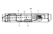
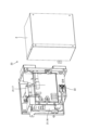
- FIG. 1 is a perspective view of a heat exchange ventilation device according to a first embodiment.
- the heat exchange ventilation device 100 according to the first embodiment has a rectangular parallelepiped box-shaped casing 1 including a top surface 1a, a bottom surface 1c, and side surfaces 1b, 1d, 1e, and 1f.
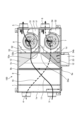
- FIG. 2 is a top view of the heat exchange ventilation device according to the first embodiment.
- FIG. 3 is a side view of the heat exchange ventilation device according to the first embodiment.
- illustration of the top surface 1a of the casing 1 is omitted, and the internal structure of the casing 1 is illustrated.
- illustration of the side surface 1d of the casing 1 on which the circuit box 2 is installed is omitted, and the internal structure of the casing 1 is illustrated.
- the casing 1 is provided with an indoor suction port 3, an outdoor suction port 4, an outdoor air outlet 5, and an indoor air outlet 6.
- the indoor suction port 3 and the outdoor suction port 4 are formed on the side surface 1e.
- the outdoor air outlet 5 and the indoor air outlet 6 are formed on the side surface 1f.
- the casing 1 includes an air supply path 10 through which air is sucked in from the outdoor suction port 4 and is blown out from the indoor air outlet 6 to each room by the air supply blower 7, and air is sucked in from the indoor suction port 3.
- An exhaust air path 11 is formed, through which the exhaust flow blown out from the outdoor outlet 5 by the exhaust blower 8 passes.
- the heat exchanger 9 is of a total heat exchange type that exchanges heat between the supply air flow passing through the supply air passage 10 and the exhaust flow passing through the exhaust air passage 11.
- the heat exchanger 9 has a columnar shape and is installed so as to straddle the supply air passage 10 and the exhaust air passage 11 with its longitudinal direction oriented in a direction intersecting each of the supply air flow and the exhaust air flow.
- the supply air blower 7 and the exhaust air blower 8 are installed side by side along the longitudinal direction of the heat exchanger 9.
- the supply air blower 7, the exhaust air blower 8, and the heat exchanger 9 are separated by a first partition plate 52. Further, the supply air blower 7 and the exhaust air blower 8 are separated by a second partition plate 51.
- the exhaust blower 8 is housed in an exhaust blower section 31 that is a part of the exhaust air path 11.
- the exhaust air blowing section 31 is a chamber space surrounded by the side surfaces 1b, 1f, the top surface 1a, and the bottom surface 1c of the casing 1, a first partition plate 52, and a second partition plate 51.
- the air supply blower 7 is housed in an air supply blower section 32 that is a part of the air supply path 10 .
- the air supply blower section 32 is a chamber space surrounded by the side surfaces 1d and 1f, the top surface 1a, and the bottom surface 1c of the casing 1, a first partition plate 52, and a second partition plate 51.
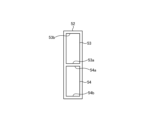
- FIG. 4 is a diagram showing the configuration of the first partition plate of the heat exchange ventilation device according to the first embodiment.
- the first partition plate 52 is provided with an exhaust opening 53 and an air supply opening 54 .
- the exhaust opening 53 is an opening that connects the exhaust air passage 11 between the exhaust air blower 8 and the heat exchanger 9, and is provided to have a width approximately equal to the width of the exhaust air blower 8.
- the air supply opening 54 is an opening that connects the air supply air path 10 between the air supply blower 7 and the heat exchanger 9, and is provided to have a width approximately equal to the width of the air supply blower 7.
- the exhaust air passage 11 between the heat exchanger 9 and the exhaust blower 8 includes two longitudinal ends 9a and 9b of the heat exchanger 9 and an exhaust opening 53 for heat exchange. It is formed in a space connecting both end portions 53a and 53b in a direction parallel to the longitudinal direction of the container 9.
- the air supply air passage 10 between the heat exchanger 9 and the air supply blower 7 includes both ends 9a, 9b in the longitudinal direction of the heat exchanger 9, and the air supply air passage 10 between the heat exchanger 9 and the air supply air blower 7. It is formed in a space connecting both end portions 54a and 54b in a direction parallel to the longitudinal direction. As shown in FIG.
- the exhaust air passage 11 and the air supply air passage 10 between the heat exchanger 9 and the exhaust blower 8 are vertically overlapped.
- the exhaust air path 11 and the air supply air path 10 have the exhaust air path 11 disposed on the lower side and the air supply air path 10 on the upper side, and are independent from each other.
- dead spaces 12 and 13 are formed between the heat exchanger 9 and the exhaust blower 8.
- the dead spaces 12 and 13 are spaces between the heat exchanger 9 and the first partition plate 52, and are spaces through which neither the supply air flow nor the exhaust air flow passes.
- the dead space 12 includes an end 9a of the heat exchanger 9 on the side of the supply air blower 7 in the arrangement direction of the supply air blower 7 and the exhaust air blower 8, and an end portion 9a of the air supply opening 54 on the side of the supply air blower 7 and the exhaust air blower 8.
- the dead space 12 is not separated from the air supply air path 10 and is connected to it, but no air supply flow therethrough.
- the dead space 13 is located at an end 9b of the heat exchanger 9 on the exhaust blower 8 side in the arrangement direction of the supply air blower 7 and the exhaust air blower 8, and at an end 9b of the exhaust opening 53 between the supply air blower 7 and the exhaust air blower 8. It is formed in a portion of the casing 1 surrounded by an end 53a on the side of the supply air blower 7 in the arrangement direction and a side surface 1b on the side of the exhaust blower 8 in the arrangement direction of the supply air blower 7 and the exhaust blower 8. . Although the dead space 13 is not separated from the exhaust air path 11 and is connected to the exhaust air path 11, the exhaust air does not flow through the dead space 13.
- the air supply path 10 is formed close to the side surface 1d of the casing 1. For this reason, the area of the dead space 12 when viewed from above can be increased compared to the case where the air supply air passage 10 is formed apart from the side surface 1d of the casing 1. Further, as shown in FIG. 2, the exhaust air passage 11 is formed closer to the side surface 1b of the casing 1. Therefore, compared to the case where the exhaust air passage 11 is formed apart from the side surface 1b of the casing 1, the area of the dead space 13 when viewed from above can be increased.
- the heat exchange ventilation device 100 also includes a control unit 23 that controls the supply air blower 7 and the exhaust air blower 8.
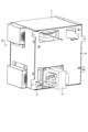
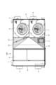
- FIG. 5 is a perspective view of the control unit of the heat exchange ventilation device according to the first embodiment.
- FIG. 6 is an exploded perspective view of the control unit of the heat exchange ventilation device according to the first embodiment.
- the control unit 23 includes a circuit board 21 , a circuit box 2 that houses the circuit board 21 , and a reactor 14 that is an electrical component installed outside the circuit box 2 .
- the circuit board 21 has an access portion that is accessed during installation, configuration, or use, and a non-access portion that is not accessed during installation, configuration, or use.
- the user operation board 17, which is an access section, is operated by the user when installing, setting, or using the heat exchange ventilation apparatus 100.
- the non-operating board 16 which is a non-accessible part, is not operated by the user when installing, setting, or using the heat exchange ventilation device 100.
- Examples of user operations performed during installation, setup, or use include wiring work during construction, initial setting operations, and user setting operations.
- the circuit board 21 and the terminal block 22 are housed in the circuit box 2.
- the reactor 14, which is a large component, is installed so as to protrude from the back surface 2a of the circuit box 2.
- a hole 15 for passing lead wires is formed on the back side of the circuit box 2.
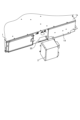
- FIG. 7 is a perspective view of the heat exchange ventilation device according to the first embodiment with the control section removed from the casing.
- An opening hole 20 is formed in the side surface 1d of the casing 1 so as to be connected to the dead space 12.
- the circuit box 2 is attached to the side surface 1d of the casing 1.
- the circuit box 2 is removably installed in a portion of the side surface 1d of the casing 1 that faces the dead space 12.
- the reactor 14 is inserted into the dead space 12 through the opening hole 20.
- the reactor 14 and the circuit board 21 are connected by a lead wire passed through the hole 15.
- the reactor 14, which has a large component size, can be installed not in the circuit box 2 but in the dead space 12 in the casing 1. Therefore, the heat exchange ventilation device 100 according to the first embodiment can reduce the size of the circuit box 2 and suppress the protrusion of the circuit box 2 to the outside of the casing 1.
- FIG. 8 is a perspective view of the control unit of the heat exchange ventilation device according to the second embodiment.
- the circuit box 2 accommodates a user operation board 17 and a terminal block 22. Note that in FIG. 8, the user operation board 17 and the terminal block 22 housed inside the circuit box 2 are not shown.
- the non-operable board 16, which is not operated by the user, is installed outside the circuit box 2 at an angle of 90 degrees from the user-operated board 17, and is provided with a separate metal plate for holding the board.
- a hole 15 for passing a lead wire is formed on the back side of the circuit box 2, and the user operation board 17 and the non-operation board 16 are connected with the lead wire through the hole 15 on the back side of the circuit box 2.
- the non-operable board 16 of the control unit 23 that is not operated by the user is installed in the dead space 12 inside the casing 1, and only the user operation board 17 and the terminal block 22 are inside the circuit box 2.
- the heat exchange ventilation device 100 according to the first embodiment there is no need to house the non-operable board 16 in the circuit box 2, so the circuit box 2 can be made smaller. Therefore, the heat exchange ventilation device 100 according to the second embodiment can reduce the amount of protrusion of the circuit box 2 to the outside of the casing 1.
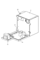
- FIG. 9 is a top view of the heat exchange ventilation device according to the third embodiment.
- illustration of the upper surface of the casing 1 is omitted, and the internal structure of the casing 1 is illustrated.
- the entire circuit box 2 is removably arranged in the dead space 12. By arranging the entire circuit box 2 in the dead space 12 and taking it out from the dead space 12 only during construction and maintenance, it is possible to suppress the protrusion of the circuit box 2 outside the casing 1, and improve heat exchange ventilation. The overall size of the device 100 can be reduced. Further, the heat exchange ventilation device 100 according to the third embodiment can avoid damaging the circuit box 2 due to collision with something during transportation.
- the heat exchange ventilation device 100 is of a parallel flow type in which the supply air flow and the exhaust flow flow in parallel, but in the heat exchange ventilation device 100, the supply air flow and the exhaust flow flow opposite each other.
- a countercurrent type may also be used.
- the configuration shown in the above embodiments shows an example of the content, and it is also possible to combine it with another known technology, or a part of the configuration can be omitted or changed without departing from the gist. It is also possible.
Abstract
A heat exchange and ventilation device (100) comprises a cuboid box-shaped casing (1) inside which a supply air passage (10) and an exhaust air passage (11) are formed, a supply air blower (7) which forms a supply air flow in the supply air passage (10), an exhaust air blower (8) which forms an exhaust air flow in the exhaust air passage (11), a heat exchanger (9) for exchanging heat between the supply air flow and the exhaust air flow, a first partitioning plate (52) that has formed therein a supply air opening portion (54) through which the supply air flow passes and an exhaust air opening portion (53) through which the exhaust air flow passes, and that is situated between the supply air blower (7) and the exhaust air blower (8), and the heat exchanger (9), a second partitioning plate (51) situated between the supply air blower (7) and the exhaust air blower (8), and a control unit (23) for controlling operations of the supply air blower (7) and the exhaust air blower (8), wherein at least a portion of the control unit (23) is accommodated in dead space (12, 13), being space between the heat exchanger (9) and the first partitioning plate (52) through which neither the supply air flow nor the exhaust air flow passes.
Description
本開示は、給気と排気との間で熱交換を行いながら換気する熱交換換気装置に関する。
The present disclosure relates to a heat exchange ventilation device that performs ventilation while exchanging heat between supply air and exhaust air.
従来、給気と排気との間で熱交換を行いながら換気する熱交換換気装置には、制御回路及び接続端子等を保護する回路ボックスが設けられている。回路ボックスは、施工時の配線作業、初期設定及びユーザ設定の際に操作しやすいよう、ケーシングの側面に取り付けられることが多い。また、熱交換換気装置は、外部接続端子の増加及び直流モータ化といった高機能化及び高性能化が求められており、回路ボックスに収容される回路基板は、大型化したり、枚数が増加したりするなどの傾向にある。回路基板の大型化及び枚数の増加にあわせて、回路ボックスも大型化し、また基板及び電装部品が階層構造で収められることが多い。
Conventionally, a heat exchange ventilation device that performs ventilation while exchanging heat between supply air and exhaust air is provided with a circuit box that protects the control circuit, connection terminals, etc. The circuit box is often attached to the side of the casing for ease of operation during wiring work, initial settings, and user settings during construction. In addition, heat exchange ventilation equipment is required to have higher functionality and performance, such as an increase in external connection terminals and a DC motor, and the circuit boards housed in the circuit box are becoming larger and increasing in number. There is a tendency to As circuit boards become larger and the number of them increases, circuit boxes also become larger, and boards and electrical components are often housed in a hierarchical structure.
特許文献1には、基板及び電装部品が階層構造で収容された回路ボックスを備えた熱交換換気装置が開示されている。
Patent Document 1 discloses a heat exchange ventilation device that includes a circuit box in which a board and electrical components are housed in a hierarchical structure.
しかしながら、ケーシングの側面に取り付けられた回路ボックスが大型化することは、熱交換換気装置の外形寸法が大きくなる原因となる。熱交換換気装置の外形寸法が大きくなると、設置上の制約により施工業者から敬遠されたり、輸送コストが増加したりといった問題が生じる。従って、ケーシング外へ突出する回路ボックスのサイズは、可能な限り小さくすることが望ましい。
However, increasing the size of the circuit box attached to the side of the casing causes the external dimensions of the heat exchange ventilation device to increase. When the external dimensions of a heat exchange ventilation device become large, problems arise such as installation restrictions that make it difficult for constructors to avoid it, and transportation costs to increase. Therefore, it is desirable to make the size of the circuit box that protrudes outside the casing as small as possible.
本開示は、上記に鑑みてなされたものであって、ケーシング外への回路ボックスの突出を抑えた熱交換換気装置を得ることを目的とする。
The present disclosure has been made in view of the above, and aims to provide a heat exchange ventilation device in which the protrusion of the circuit box to the outside of the casing is suppressed.
上述した課題を解決し、目的を達成するために、本開示に係る熱交換換気装置は、室外から外気を取り込む室外側吸込口と、室外側吸込口から取り込まれた外気を室内へ供給する室内側吹出口と、室内の空気を取り込む室内側吸込口と、室内側吸込口から取り込んだ室内空気を室外へ排出する室外側吹出口とを有する直方体箱状であり、内部に室外側吸込口と室内側吹出口とを繋ぐ給気風路と、室内側吸込口と室外側吹出口とを繋ぐ排気風路とが形成されたケーシングと、給気風路に設置されて、給気風路に給気流を形成する給気送風機と、排気風路に設置されて、排気風路に排気流を形成する排気送風機と、柱状であり、給気流及び排気流の各々と交差する方向に長手方向を向けて給気風路と排気風路とに跨がって設置されて、給気流と排気流との間で熱交換を行う熱交換器と、給気流が通る給気開口部と排気流が通る排気開口部とが形成されており、給気送風機及び排気送風機と熱交換器との間に設置される第1仕切板と、給気送風機と排気送風機との間に設置される第2仕切板と、給気送風機及び排気送風機の運転を制御する制御部とを備える。制御部の少なくとも一部は、熱交換器と第1仕切板との間の空間かつ給気流及び排気流のいずれも通過しない空間であるデッドスペースに収容されている。
In order to solve the above-mentioned problems and achieve the purpose, a heat exchange ventilation device according to the present disclosure has an outdoor side suction port that takes in outside air from outside, and an indoor side suction port that supplies outside air taken in from the outdoor side suction port to the room. It has the shape of a rectangular parallelepiped box that has an inner air outlet, an indoor air inlet that takes in indoor air, and an outdoor air outlet that exhausts the indoor air taken in from the indoor air inlet to the outdoors. A casing is provided with an air supply path connecting the indoor air outlet and an exhaust air path connecting the indoor air intake port and the outdoor air outlet. an exhaust blower installed in the exhaust air passage to form an exhaust air flow in the exhaust air passage; and an exhaust air blower installed in the exhaust air passage to form an exhaust air flow in the exhaust air passage; A heat exchanger installed across an air passage and an exhaust air passage to exchange heat between the supply air flow and the exhaust air flow, an air supply opening through which the supply air flow passes, and an exhaust opening through which the exhaust flow passes. A first partition plate installed between the supply air blower and the exhaust air blower and the heat exchanger, a second partition plate installed between the supply air blower and the exhaust air blower, and a control unit that controls the operation of the air blower and the exhaust blower. At least a portion of the control unit is accommodated in a dead space that is a space between the heat exchanger and the first partition plate and a space through which neither the supply air flow nor the exhaust air flow passes.
本開示に係る熱交換換気装置は、ケーシング外への回路ボックスの突出を抑えられるという効果を奏する。
The heat exchange ventilation device according to the present disclosure has the effect of suppressing the protrusion of the circuit box to the outside of the casing.
以下に、実施の形態に係る熱交換換気装置を図面に基づいて詳細に説明する。
Hereinafter, a heat exchange ventilation device according to an embodiment will be described in detail based on the drawings.
実施の形態1.
図1は、実施の形態1に係る熱交換換気装置の斜視図である。実施の形態1に係る熱交換換気装置100は、天面1a、底面1c及び側面1b,1d,1e,1fを備える直方体箱形状のケーシング1を有する。Embodiment 1.
FIG. 1 is a perspective view of a heat exchange ventilation device according to a first embodiment. The heatexchange ventilation device 100 according to the first embodiment has a rectangular parallelepiped box-shaped casing 1 including a top surface 1a, a bottom surface 1c, and side surfaces 1b, 1d, 1e, and 1f.
図1は、実施の形態1に係る熱交換換気装置の斜視図である。実施の形態1に係る熱交換換気装置100は、天面1a、底面1c及び側面1b,1d,1e,1fを備える直方体箱形状のケーシング1を有する。
FIG. 1 is a perspective view of a heat exchange ventilation device according to a first embodiment. The heat
図2は、実施の形態1に係る熱交換換気装置の上面図である。図3は、実施の形態1に係る熱交換換気装置の側面図である。なお、図2では、ケーシング1の天面1aの図示を省略してケーシング1の内部の構造を図示している。また、図3では、ケーシング1のうち回路ボックス2が設置される側面1dの図示を省略してケーシング1の内部の構造を図示している。図2に示されるように、ケーシング1には、室内側吸込口3、室外側吸込口4、室外側吹出口5及び室内側吹出口6が形成されている。室内側吸込口3及び室外側吸込口4は、側面1eに形成されている。室外側吹出口5及び室内側吹出口6は、側面1fに形成されている。
FIG. 2 is a top view of the heat exchange ventilation device according to the first embodiment. FIG. 3 is a side view of the heat exchange ventilation device according to the first embodiment. In addition, in FIG. 2, illustration of the top surface 1a of the casing 1 is omitted, and the internal structure of the casing 1 is illustrated. Moreover, in FIG. 3, illustration of the side surface 1d of the casing 1 on which the circuit box 2 is installed is omitted, and the internal structure of the casing 1 is illustrated. As shown in FIG. 2, the casing 1 is provided with an indoor suction port 3, an outdoor suction port 4, an outdoor air outlet 5, and an indoor air outlet 6. The indoor suction port 3 and the outdoor suction port 4 are formed on the side surface 1e. The outdoor air outlet 5 and the indoor air outlet 6 are formed on the side surface 1f.
ケーシング1の内部には、給気送風機7、排気送風機8及び熱交換器9が配置されている。ケーシング1には、室外側吸込口4から吸い込まれ、給気送風機7によって室内側吹出口6から各部屋に吹き出される給気流が通る給気風路10と、室内側吸込口3から吸い込まれ、排気送風機8によって室外側吹出口5から屋外に吹き出される排気流が通る排気風路11とが形成されている。熱交換器9は、給気風路10を通る給気流と排気風路11を通る排気流との間で熱交換を行う全熱交換形である。熱交換器9は、柱状であり、給気流及び排気流の各々と交差する方向に長手方向を向けて、給気風路10と排気風路11とに跨がって設置されている。
Inside the casing 1, a supply air blower 7, an exhaust air blower 8, and a heat exchanger 9 are arranged. The casing 1 includes an air supply path 10 through which air is sucked in from the outdoor suction port 4 and is blown out from the indoor air outlet 6 to each room by the air supply blower 7, and air is sucked in from the indoor suction port 3. An exhaust air path 11 is formed, through which the exhaust flow blown out from the outdoor outlet 5 by the exhaust blower 8 passes. The heat exchanger 9 is of a total heat exchange type that exchanges heat between the supply air flow passing through the supply air passage 10 and the exhaust flow passing through the exhaust air passage 11. The heat exchanger 9 has a columnar shape and is installed so as to straddle the supply air passage 10 and the exhaust air passage 11 with its longitudinal direction oriented in a direction intersecting each of the supply air flow and the exhaust air flow.
図2に示すように、給気送風機7及び排気送風機8は、熱交換器9の長手方向に沿って並んで設置されている。給気送風機7及び排気送風機8と、熱交換器9とは、第1仕切板52で隔てられている。また、給気送風機7と排気送風機8とは、第2仕切板51で隔てられている。
As shown in FIG. 2, the supply air blower 7 and the exhaust air blower 8 are installed side by side along the longitudinal direction of the heat exchanger 9. The supply air blower 7, the exhaust air blower 8, and the heat exchanger 9 are separated by a first partition plate 52. Further, the supply air blower 7 and the exhaust air blower 8 are separated by a second partition plate 51.
図2に示すように、排気送風機8は、排気風路11の一部である排気送風部31に収容されている。排気送風部31は、ケーシング1の側面1b,1f、天面1a及び底面1cと、第1仕切板52と、第2仕切板51とで囲われたチャンバー空間である。給気送風機7は、給気風路10の一部である給気送風部32に収容されている。給気送風部32は、ケーシング1の側面1d,1f、天面1a及び底面1cと、第1仕切板52と、第2仕切板51とで囲われたチャンバー空間である。
As shown in FIG. 2, the exhaust blower 8 is housed in an exhaust blower section 31 that is a part of the exhaust air path 11. The exhaust air blowing section 31 is a chamber space surrounded by the side surfaces 1b, 1f, the top surface 1a, and the bottom surface 1c of the casing 1, a first partition plate 52, and a second partition plate 51. The air supply blower 7 is housed in an air supply blower section 32 that is a part of the air supply path 10 . The air supply blower section 32 is a chamber space surrounded by the side surfaces 1d and 1f, the top surface 1a, and the bottom surface 1c of the casing 1, a first partition plate 52, and a second partition plate 51.
図4は、実施の形態1に係る熱交換換気装置の第1仕切板の構成を示す図である。第1仕切板52には、排気開口部53及び給気開口部54が設けられている。排気開口部53は、排気送風機8と熱交換器9との間で排気風路11をつなげる開口であり、排気送風機8の幅と同等程度に設けられている。給気開口部54は、給気送風機7と熱交換器9との間で給気風路10をつなげる開口であり、給気送風機7の幅と同等程度に設けられている。
FIG. 4 is a diagram showing the configuration of the first partition plate of the heat exchange ventilation device according to the first embodiment. The first partition plate 52 is provided with an exhaust opening 53 and an air supply opening 54 . The exhaust opening 53 is an opening that connects the exhaust air passage 11 between the exhaust air blower 8 and the heat exchanger 9, and is provided to have a width approximately equal to the width of the exhaust air blower 8. The air supply opening 54 is an opening that connects the air supply air path 10 between the air supply blower 7 and the heat exchanger 9, and is provided to have a width approximately equal to the width of the air supply blower 7.
図2に示すように、熱交換器9と排気送風機8との間における排気風路11は、熱交換器9の長手方向の両方の端部9a,9bと、排気開口部53のうち熱交換器9の長手方向に平行な方向の両方の端部53a,53bとを結んだ空間に形成されている。同様に、熱交換器9と給気送風機7との間における給気風路10は、熱交換器9の長手方向の両方の端部9a,9bと、給気開口部54のうち熱交換器9の長手方向に平行な方向の両方の端部54a,54bとを結んだ空間に形成されている。図3に示すように、熱交換器9と排気送風機8との間における排気風路11及び給気風路10は、上下に重なっている。排気風路11及び給気風路10は、下側に排気風路11が配置され、上側に給気風路10が配置されており、互いに独立した風路となっている。
As shown in FIG. 2, the exhaust air passage 11 between the heat exchanger 9 and the exhaust blower 8 includes two longitudinal ends 9a and 9b of the heat exchanger 9 and an exhaust opening 53 for heat exchange. It is formed in a space connecting both end portions 53a and 53b in a direction parallel to the longitudinal direction of the container 9. Similarly, the air supply air passage 10 between the heat exchanger 9 and the air supply blower 7 includes both ends 9a, 9b in the longitudinal direction of the heat exchanger 9, and the air supply air passage 10 between the heat exchanger 9 and the air supply air blower 7. It is formed in a space connecting both end portions 54a and 54b in a direction parallel to the longitudinal direction. As shown in FIG. 3, the exhaust air passage 11 and the air supply air passage 10 between the heat exchanger 9 and the exhaust blower 8 are vertically overlapped. The exhaust air path 11 and the air supply air path 10 have the exhaust air path 11 disposed on the lower side and the air supply air path 10 on the upper side, and are independent from each other.
図2に示すように、熱交換器9と排気送風機8との間には、デッドスペース12,13が形成されている。デッドスペース12,13は、熱交換器9と第1仕切板52との間の空間かつ給気流及び排気流のいずれも通過しない空間である。デッドスペース12は、熱交換器9のうち給気送風機7と排気送風機8との配列方向において給気送風機7側の端部9aと、給気開口部54のうち給気送風機7と排気送風機8との配列方向において排気送風機8側の端部54aと、ケーシング1のうち、給気送風機7と排気送風機8との配列方向において給気送風機7側の側面1dとに囲まれた部分に形成されている。デッドスペース12は、給気風路10と隔てられておらず繋がってはいるが、給気流は流れない。
As shown in FIG. 2, dead spaces 12 and 13 are formed between the heat exchanger 9 and the exhaust blower 8. The dead spaces 12 and 13 are spaces between the heat exchanger 9 and the first partition plate 52, and are spaces through which neither the supply air flow nor the exhaust air flow passes. The dead space 12 includes an end 9a of the heat exchanger 9 on the side of the supply air blower 7 in the arrangement direction of the supply air blower 7 and the exhaust air blower 8, and an end portion 9a of the air supply opening 54 on the side of the supply air blower 7 and the exhaust air blower 8. It is formed in a portion of the casing 1 surrounded by the end 54a on the exhaust blower 8 side in the arrangement direction of the supply air blower 7 and the exhaust blower 8, and the side surface 1d on the supply air blower 7 side in the arrangement direction of the supply air blower 7 and the exhaust blower 8. ing. The dead space 12 is not separated from the air supply air path 10 and is connected to it, but no air supply flow therethrough.
デッドスペース13は、熱交換器9のうち給気送風機7と排気送風機8との配列方向において排気送風機8側の端部9bと、排気開口部53のうち給気送風機7と排気送風機8との配列方向において給気送風機7側の端部53aと、ケーシング1のうち、給気送風機7と排気送風機8との配列方向において排気送風機8側の側面1bとに囲まれた部分に形成されている。デッドスペース13は、排気風路11と隔てられておらず繋がってはいるが、排気流は流れない。
The dead space 13 is located at an end 9b of the heat exchanger 9 on the exhaust blower 8 side in the arrangement direction of the supply air blower 7 and the exhaust air blower 8, and at an end 9b of the exhaust opening 53 between the supply air blower 7 and the exhaust air blower 8. It is formed in a portion of the casing 1 surrounded by an end 53a on the side of the supply air blower 7 in the arrangement direction and a side surface 1b on the side of the exhaust blower 8 in the arrangement direction of the supply air blower 7 and the exhaust blower 8. . Although the dead space 13 is not separated from the exhaust air path 11 and is connected to the exhaust air path 11, the exhaust air does not flow through the dead space 13.
図2に示すように、給気風路10は、ケーシング1の側面1dに寄せて形成されている。このため、給気風路10がケーシング1の側面1dから離れて形成されている場合と比較して、デッドスペース12の上面視での面積を大きくすることができる。また、図2に示すように、排気風路11は、ケーシング1の側面1bに寄せて形成されている。このため、排気風路11がケーシング1の側面1bから離れて形成されている場合と比較して、デッドスペース13の上面視での面積を大きくすることができる。
As shown in FIG. 2, the air supply path 10 is formed close to the side surface 1d of the casing 1. For this reason, the area of the dead space 12 when viewed from above can be increased compared to the case where the air supply air passage 10 is formed apart from the side surface 1d of the casing 1. Further, as shown in FIG. 2, the exhaust air passage 11 is formed closer to the side surface 1b of the casing 1. Therefore, compared to the case where the exhaust air passage 11 is formed apart from the side surface 1b of the casing 1, the area of the dead space 13 when viewed from above can be increased.
また、熱交換換気装置100は、給気送風機7及び排気送風機8を制御する制御部23を備えている。図5は、実施の形態1に係る熱交換換気装置の制御部の斜視図である。図6は、実施の形態1に係る熱交換換気装置の制御部の分解斜視図である。制御部23は、回路基板21と、回路基板21を収納する回路ボックス2と、回路ボックス2の外側に設置された電気部品であるリアクトル14とを備える。回路基板21は、設置時、設定時又は使用時にアクセスされるアクセス部と、設置時、設定時又は使用時にアクセスされない非アクセス部とを有している。アクセス部であるユーザ操作基板17は、熱交換換気装置100の設置時、設定時又は使用時に、ユーザによる操作が行われる。非アクセス部である非操作基板16は、熱交換換気装置100の設置時、設定時又は使用時にユーザ操作は行われない。設置時、設定時又は使用時に行われるユーザ操作とは、施工時の配線作業、初期設定操作、及びユーザ設定操作を例示できる。図5に示すように、回路基板21及び端子台22は、回路ボックス2内に収納されている。また、部品サイズの大きいリアクトル14は、回路ボックス2の裏面2aから突出して設置されている。回路ボックス2の裏側にはリード線通し用の穴15が形成されている。
The heat exchange ventilation device 100 also includes a control unit 23 that controls the supply air blower 7 and the exhaust air blower 8. FIG. 5 is a perspective view of the control unit of the heat exchange ventilation device according to the first embodiment. FIG. 6 is an exploded perspective view of the control unit of the heat exchange ventilation device according to the first embodiment. The control unit 23 includes a circuit board 21 , a circuit box 2 that houses the circuit board 21 , and a reactor 14 that is an electrical component installed outside the circuit box 2 . The circuit board 21 has an access portion that is accessed during installation, configuration, or use, and a non-access portion that is not accessed during installation, configuration, or use. The user operation board 17, which is an access section, is operated by the user when installing, setting, or using the heat exchange ventilation apparatus 100. The non-operating board 16, which is a non-accessible part, is not operated by the user when installing, setting, or using the heat exchange ventilation device 100. Examples of user operations performed during installation, setup, or use include wiring work during construction, initial setting operations, and user setting operations. As shown in FIG. 5, the circuit board 21 and the terminal block 22 are housed in the circuit box 2. Moreover, the reactor 14, which is a large component, is installed so as to protrude from the back surface 2a of the circuit box 2. A hole 15 for passing lead wires is formed on the back side of the circuit box 2.
図7は、実施の形態1に係る熱交換換気装置の制御部をケーシングから取り外した状態での斜視図である。ケーシング1の側面1dには、デッドスペース12に繋がるように開口した開口穴20が形成されている。
FIG. 7 is a perspective view of the heat exchange ventilation device according to the first embodiment with the control section removed from the casing. An opening hole 20 is formed in the side surface 1d of the casing 1 so as to be connected to the dead space 12.
図2に示すように、回路ボックス2は、ケーシング1の側面1dに取り付けられる。回路ボックス2は、ケーシング1の側面1dのうち、デッドスペース12に対向する部分に着脱可能に設置される。回路ボックス2をケーシング1の側面1dに設置すると、開口穴20を通してリアクトル14がデッドスペース12に挿入される。リアクトル14と回路基板21とは、穴15を通されたリード線により接続される。
As shown in FIG. 2, the circuit box 2 is attached to the side surface 1d of the casing 1. The circuit box 2 is removably installed in a portion of the side surface 1d of the casing 1 that faces the dead space 12. When the circuit box 2 is installed on the side surface 1d of the casing 1, the reactor 14 is inserted into the dead space 12 through the opening hole 20. The reactor 14 and the circuit board 21 are connected by a lead wire passed through the hole 15.
実施の形態1に係る熱交換換気装置100は、部品サイズが大きいリアクトル14を回路ボックス2内ではなく、ケーシング1内のデッドスペース12に設置することができる。したがって、実施の形態1に係る熱交換換気装置100は、回路ボックス2のサイズダウンを図り、ケーシング1外への回路ボックス2の突出を抑制できる。
In the heat exchange ventilation system 100 according to the first embodiment, the reactor 14, which has a large component size, can be installed not in the circuit box 2 but in the dead space 12 in the casing 1. Therefore, the heat exchange ventilation device 100 according to the first embodiment can reduce the size of the circuit box 2 and suppress the protrusion of the circuit box 2 to the outside of the casing 1.
実施の形態2.
実施の形態2に係る熱交換換気装置100は、制御部23の構成が実施の形態1に係る熱交換換気装置100とは異なる。図8は、実施の形態2に係る熱交換換気装置の制御部の斜視図である。回路ボックス2には、ユーザ操作基板17及び端子台22が収容されている。なお、図8では、回路ボックス2内部に収容されたユーザ操作基板17及び端子台22は不図示となっている。ユーザが操作しない非操作基板16は、ユーザ操作基板17とは90°角度が変えて回路ボックス2の外部に設置されており、別途基板を保持する板金が設けられている。回路ボックス2の裏側にはリード線通し用の穴15が形成されており、ユーザ操作基板17と非操作基板16とは、回路ボックス2の裏側の穴15を通じてリード線で接続されている。Embodiment 2.
The heatexchange ventilation device 100 according to the second embodiment is different from the heat exchange ventilation device 100 according to the first embodiment in the configuration of the control unit 23. FIG. 8 is a perspective view of the control unit of the heat exchange ventilation device according to the second embodiment. The circuit box 2 accommodates a user operation board 17 and a terminal block 22. Note that in FIG. 8, the user operation board 17 and the terminal block 22 housed inside the circuit box 2 are not shown. The non-operable board 16, which is not operated by the user, is installed outside the circuit box 2 at an angle of 90 degrees from the user-operated board 17, and is provided with a separate metal plate for holding the board. A hole 15 for passing a lead wire is formed on the back side of the circuit box 2, and the user operation board 17 and the non-operation board 16 are connected with the lead wire through the hole 15 on the back side of the circuit box 2.
実施の形態2に係る熱交換換気装置100は、制御部23の構成が実施の形態1に係る熱交換換気装置100とは異なる。図8は、実施の形態2に係る熱交換換気装置の制御部の斜視図である。回路ボックス2には、ユーザ操作基板17及び端子台22が収容されている。なお、図8では、回路ボックス2内部に収容されたユーザ操作基板17及び端子台22は不図示となっている。ユーザが操作しない非操作基板16は、ユーザ操作基板17とは90°角度が変えて回路ボックス2の外部に設置されており、別途基板を保持する板金が設けられている。回路ボックス2の裏側にはリード線通し用の穴15が形成されており、ユーザ操作基板17と非操作基板16とは、回路ボックス2の裏側の穴15を通じてリード線で接続されている。
The heat
上記構造にすることで、制御部23のうちユーザが操作しない非操作基板16については、ケーシング1内のデッドスペース12に設置され、回路ボックス2内にはユーザ操作基板17及び端子台22のみが格納される。したがって、実施の形態1に係る熱交換換気装置100は、回路ボックス2に非操作基板16を収容する必要がないため、回路ボックス2を小型化できる。このため、実施の形態2に係る熱交換換気装置100は、ケーシング1外への回路ボックス2の突出量を低減できる。
With the above structure, the non-operable board 16 of the control unit 23 that is not operated by the user is installed in the dead space 12 inside the casing 1, and only the user operation board 17 and the terminal block 22 are inside the circuit box 2. Stored. Therefore, in the heat exchange ventilation device 100 according to the first embodiment, there is no need to house the non-operable board 16 in the circuit box 2, so the circuit box 2 can be made smaller. Therefore, the heat exchange ventilation device 100 according to the second embodiment can reduce the amount of protrusion of the circuit box 2 to the outside of the casing 1.
実施の形態3.
図9は、実施の形態3に係る熱交換換気装置の上面図である。なお、図9では、ケーシング1の上面の図示を省略してケーシング1の内部の構造を図示している。実施の形態3に係る熱交換換気装置100は、回路ボックス2全体が着脱可能にデッドスペース12に配置されている。回路ボックス2全体をデッドスペース12に配置し、施工時及びメンテナンス時のみ回路ボックス2をデッドスペース12から出す構造とすることで、ケーシング1外への回路ボックス2の突出を抑制でき、熱交換換気装置100全体の小型化を実現できる。また、実施の形態3に係る熱交換換気装置100は、運搬時に回路ボックス2を何かに衝突させて破損させてしまうことを回避できる。 Embodiment 3.
FIG. 9 is a top view of the heat exchange ventilation device according to the third embodiment. In addition, in FIG. 9, illustration of the upper surface of thecasing 1 is omitted, and the internal structure of the casing 1 is illustrated. In the heat exchange ventilation device 100 according to the third embodiment, the entire circuit box 2 is removably arranged in the dead space 12. By arranging the entire circuit box 2 in the dead space 12 and taking it out from the dead space 12 only during construction and maintenance, it is possible to suppress the protrusion of the circuit box 2 outside the casing 1, and improve heat exchange ventilation. The overall size of the device 100 can be reduced. Further, the heat exchange ventilation device 100 according to the third embodiment can avoid damaging the circuit box 2 due to collision with something during transportation.
図9は、実施の形態3に係る熱交換換気装置の上面図である。なお、図9では、ケーシング1の上面の図示を省略してケーシング1の内部の構造を図示している。実施の形態3に係る熱交換換気装置100は、回路ボックス2全体が着脱可能にデッドスペース12に配置されている。回路ボックス2全体をデッドスペース12に配置し、施工時及びメンテナンス時のみ回路ボックス2をデッドスペース12から出す構造とすることで、ケーシング1外への回路ボックス2の突出を抑制でき、熱交換換気装置100全体の小型化を実現できる。また、実施の形態3に係る熱交換換気装置100は、運搬時に回路ボックス2を何かに衝突させて破損させてしまうことを回避できる。 Embodiment 3.
FIG. 9 is a top view of the heat exchange ventilation device according to the third embodiment. In addition, in FIG. 9, illustration of the upper surface of the
なお、上記の説明においては、給気風路10側で生じたデッドスペース12に制御部23の一部又は全部を収納した例を示したが、排気風路11側で生じたデッドスペース13を用いてもよい。また、上記の説明においては、給気流と排気流とが並行して流れる並流型の熱交換換気装置100について説明したが、熱交換換気装置100は、給気流と排気流とが向かい合って流れる向流型であってもよい。
In the above explanation, an example was shown in which a part or all of the control unit 23 is housed in the dead space 12 created on the side of the air supply air path 10, but it is also possible to use the dead space 13 created on the side of the exhaust air path 11. You can. Further, in the above description, the heat exchange ventilation device 100 is of a parallel flow type in which the supply air flow and the exhaust flow flow in parallel, but in the heat exchange ventilation device 100, the supply air flow and the exhaust flow flow opposite each other. A countercurrent type may also be used.
以上の実施の形態に示した構成は、内容の一例を示すものであり、別の公知の技術と組み合わせることも可能であるし、要旨を逸脱しない範囲で、構成の一部を省略、変更することも可能である。
The configuration shown in the above embodiments shows an example of the content, and it is also possible to combine it with another known technology, or a part of the configuration can be omitted or changed without departing from the gist. It is also possible.
1 ケーシング、1a 天面、1b,1d,1e,1f 側面、1c 底面、2 回路ボックス、2a 裏面、3 室内側吸込口、4 室外側吸込口、5 室外側吹出口、6 室内側吹出口、7 給気送風機、8 排気送風機、9 熱交換器、9a,9b,53a,53b,54a,54b 端部、10 給気風路、11 排気風路、12,13 デッドスペース、14 リアクトル、15 穴、16 非操作基板、17 ユーザ操作基板、20 開口穴、21 回路基板、22 端子台、23 制御部、31 排気送風部、32 給気送風部、51 第2仕切板、52 第1仕切板、53 排気開口部、54 給気開口部、100 熱交換換気装置。
1 Casing, 1a Top surface, 1b, 1d, 1e, 1f Side surfaces, 1c Bottom surface, 2 Circuit box, 2a Back surface, 3 Indoor suction port, 4 Outdoor suction port, 5 Outdoor air outlet, 6 Indoor air outlet, 7 Supply air blower, 8 Exhaust air blower, 9 Heat exchanger, 9a, 9b, 53a, 53b, 54a, 54b end, 10 Supply air path, 11 Exhaust air path, 12, 13 Dead space, 14 Reactor, 15 Hole, 16 Non-operation board, 17 User operation board, 20 Opening hole, 21 Circuit board, 22 Terminal block, 23 Control unit, 31 Exhaust air blower, 32 Supply air blower, 51 Second partition plate, 52 First partition plate, 53 Exhaust opening, 54 air supply opening, 100 heat exchange ventilation device.
Claims (7)
- 室外から外気を取り込む室外側吸込口と、前記室外側吸込口から取り込まれた外気を室内へ供給する室内側吹出口と、室内の空気を取り込む室内側吸込口と、前記室内側吸込口から取り込んだ室内空気を室外へ排出する室外側吹出口とを有する直方体箱状であり、内部に前記室外側吸込口と前記室内側吹出口とを繋ぐ給気風路と、前記室内側吸込口と前記室外側吹出口とを繋ぐ排気風路とが形成されたケーシングと、
前記給気風路に設置されて、前記給気風路に給気流を形成する給気送風機と、
前記排気風路に設置されて、前記排気風路に排気流を形成する排気送風機と、
柱状であり、前記給気流及び前記排気流の各々と交差する方向に長手方向を向けて前記給気風路と前記排気風路とに跨がって設置されて、前記給気流と前記排気流との間で熱交換を行う熱交換器と、
前記給気流が通る給気開口部と前記排気流が通る排気開口部とが形成されており、前記給気送風機及び前記排気送風機と前記熱交換器との間に設置される第1仕切板と、
前記給気送風機と前記排気送風機との間に設置される第2仕切板と、
前記給気送風機及び前記排気送風機の運転を制御する制御部とを備え、
前記制御部の少なくとも一部は、前記熱交換器と前記第1仕切板との間の空間かつ前記給気流及び前記排気流のいずれも通過しない空間であるデッドスペースに収容されていることを特徴とする熱交換換気装置。 an outdoor air inlet that takes in outside air from the outdoors; an indoor air outlet that supplies the outside air taken in from the outdoor air inlet into the room; an indoor air intake that takes in indoor air; and an indoor air intake that takes in air from the indoor air inlet. It has the shape of a rectangular parallelepiped box having an outdoor air outlet for discharging indoor air to the outdoors, and an air supply air passage connecting the indoor air intake and the indoor air outlet inside, and an air supply air passage connecting the indoor air intake and the indoor air outlet. A casing in which an exhaust air passage connecting the outer air outlet is formed;
a supply air blower installed in the supply air path to form a supply air flow in the supply air path;
an exhaust blower installed in the exhaust air passage to form an exhaust flow in the exhaust air passage;
It is columnar and is installed astride the supply air passage and the exhaust air passage with its longitudinal direction oriented in a direction intersecting each of the supply air flow and the exhaust air flow, so that the air supply flow and the exhaust flow are connected to each other. a heat exchanger that exchanges heat between
an air supply opening through which the supply air flow passes and an exhaust opening through which the exhaust air flow passes; a first partition plate installed between the supply air blower and the exhaust air blower and the heat exchanger; ,
a second partition plate installed between the supply air blower and the exhaust air blower;
a control unit that controls the operation of the supply air blower and the exhaust blower,
At least a portion of the control unit is housed in a dead space that is a space between the heat exchanger and the first partition plate and through which neither the supply air flow nor the exhaust air flow passes. heat exchange ventilation equipment. - 前記給気送風機及び前記排気送風機は、前記熱交換器の長手方向に沿って並んで設置されており、
前記デッドスペースは、前記ケーシングの内部かつ前記熱交換器のうち前記給気送風機と前記排気送風機との配列方向において前記給気送風機側の端部と、前記排気開口部のうち前記給気送風機と前記排気送風機との配列方向において前記排気送風機側の端部と、前記ケーシングのうち、前記給気送風機と前記排気送風機との配列方向において前記給気送風機側の側面とに囲まれた部分、又は、前記熱交換器のうち前記給気送風機と前記排気送風機との配列方向において前記排気送風機側の端部と、前記給気開口部のうち前記給気送風機と前記排気送風機との配列方向において前記給気送風機側の端部と、前記ケーシングのうち、前記給気送風機と前記排気送風機との配列方向において前記排気送風機側の側面とに囲まれた部分に形成されていることを特徴とする請求項1に記載の熱交換換気装置。 The supply air blower and the exhaust air blower are installed side by side along the longitudinal direction of the heat exchanger,
The dead space is located inside the casing and at an end of the heat exchanger on the side of the supply air blower in the arrangement direction of the supply air blower and the exhaust blower, and at an end of the exhaust opening on the side of the supply air blower. a portion of the casing surrounded by an end on the exhaust blower side in the arrangement direction with the exhaust air blower and a side surface on the supply air blower side in the arrangement direction with the supply air blower and the exhaust air blower; , an end of the heat exchanger on the exhaust blower side in the arrangement direction of the supply air blower and the exhaust air blower, and an end part of the air supply opening on the side of the exhaust air blower in the arrangement direction of the supply air blower and the exhaust air blower; A claim characterized in that the air supply blower is formed in a portion surrounded by an end portion of the casing on the side of the air supply blower and a side surface of the casing on the side of the exhaust air blower in the arrangement direction of the air supply blower and the exhaust air blower. The heat exchange ventilation device according to item 1. - 前記制御部は、
回路基板と、
前記回路基板を収納する回路ボックスと、
前記回路ボックスの外側に設置された電気部品とを備え、
前記電気部品が前記デッドスペースに収納され、かつ、前記回路ボックスが前記ケーシングの外側に位置する状態で、前記制御部が前記ケーシングに取り付けられたことを特徴とする請求項1又は2に記載の熱交換換気装置。 The control unit includes:
a circuit board;
a circuit box that stores the circuit board;
and an electrical component installed outside the circuit box,
3. The control unit according to claim 1 or 2, wherein the control unit is attached to the casing with the electrical component stored in the dead space and the circuit box positioned outside the casing. Heat exchange ventilation equipment. - 前記電気部品は、リアクトルであることを特徴とする請求項3に記載の熱交換換気装置。 The heat exchange ventilation system according to claim 3, wherein the electric component is a reactor.
- 前記制御部は、ユーザ操作が行われるアクセス部と、ユーザ操作が行われない非アクセス部とを有し、
前記非アクセス部が前記デッドスペースに収納され、かつ、前記アクセス部が前記ケーシングの外に配置される状態で前記制御部が前記ケーシングに取り付けられたことを特徴とする請求項1又は2に記載の熱交換換気装置。 The control section has an access section where user operations are performed and a non-access section where user operations are not performed,
3. The control section is attached to the casing with the non-access section housed in the dead space and the access section disposed outside the casing. heat exchange ventilation equipment. - 前記アクセス部は、制御の設定を行う操作基板及び端子台の少なくとも一方を含むことを特徴とする請求項5に記載の熱交換換気装置。 The heat exchange ventilation device according to claim 5, wherein the access section includes at least one of an operation board and a terminal block for performing control settings.
- 前記給気流と前記排気流とが並行して流れる並流型、又は前記給気流と前記排気流とが向かい合って流れる向流型であることを特徴とする請求項1から6のいずれか1項に記載の熱交換換気装置。 Any one of claims 1 to 6, characterized in that it is a parallel flow type in which the supply air flow and the exhaust flow flow in parallel, or a countercurrent type in which the supply air flow and the exhaust flow flow face each other. Heat exchange ventilation equipment as described in.
Priority Applications (1)
| Application Number | Priority Date | Filing Date | Title |
|---|---|---|---|
| PCT/JP2022/024549 WO2023248296A1 (en) | 2022-06-20 | 2022-06-20 | Heat exchange and ventilation device |
Applications Claiming Priority (1)
| Application Number | Priority Date | Filing Date | Title |
|---|---|---|---|
| PCT/JP2022/024549 WO2023248296A1 (en) | 2022-06-20 | 2022-06-20 | Heat exchange and ventilation device |
Publications (1)
| Publication Number | Publication Date |
|---|---|
| WO2023248296A1 true WO2023248296A1 (en) | 2023-12-28 |
Family
ID=89379487
Family Applications (1)
| Application Number | Title | Priority Date | Filing Date |
|---|---|---|---|
| PCT/JP2022/024549 WO2023248296A1 (en) | 2022-06-20 | 2022-06-20 | Heat exchange and ventilation device |
Country Status (1)
| Country | Link |
|---|---|
| WO (1) | WO2023248296A1 (en) |
Citations (4)
| Publication number | Priority date | Publication date | Assignee | Title |
|---|---|---|---|---|
| JPS58104824U (en) * | 1982-01-13 | 1983-07-16 | 三菱電機株式会社 | Ventilation fan with built-in heat exchanger |
| JPH03156236A (en) * | 1989-11-14 | 1991-07-04 | Matsushita Seiko Co Ltd | Ventilation device |
| JPH0473539A (en) * | 1990-07-11 | 1992-03-09 | Matsushita Seiko Co Ltd | Ventilation device |
| JP2006084039A (en) * | 2004-09-14 | 2006-03-30 | Hitachi Home & Life Solutions Inc | Air conditioning ventilation fan |
-
2022
- 2022-06-20 WO PCT/JP2022/024549 patent/WO2023248296A1/en unknown
Patent Citations (4)
| Publication number | Priority date | Publication date | Assignee | Title |
|---|---|---|---|---|
| JPS58104824U (en) * | 1982-01-13 | 1983-07-16 | 三菱電機株式会社 | Ventilation fan with built-in heat exchanger |
| JPH03156236A (en) * | 1989-11-14 | 1991-07-04 | Matsushita Seiko Co Ltd | Ventilation device |
| JPH0473539A (en) * | 1990-07-11 | 1992-03-09 | Matsushita Seiko Co Ltd | Ventilation device |
| JP2006084039A (en) * | 2004-09-14 | 2006-03-30 | Hitachi Home & Life Solutions Inc | Air conditioning ventilation fan |
Similar Documents
| Publication | Publication Date | Title |
|---|---|---|
| JP4923107B2 (en) | Air conditioner outdoor unit | |
| JP3985835B2 (en) | Electrical component assembly and outdoor unit of air conditioner including the same | |
| WO2012111556A1 (en) | Package-stored engine work machine | |
| JP2007127378A (en) | Electrical equipment assembly, outdoor unit of air conditioner comprising the same, and air conditioner | |
| JP3259719B2 (en) | Air conditioner | |
| JP2009156559A (en) | Indoor unit for air conditioner | |
| WO2023248296A1 (en) | Heat exchange and ventilation device | |
| JP3287343B2 (en) | Air conditioner | |
| JP2008292068A (en) | Outdoor unit of air-conditioner | |
| JP4756579B2 (en) | Air conditioner | |
| JP5202434B2 (en) | Simultaneous exhaust / exhaust fan | |
| JP4765095B2 (en) | Box device | |
| JP4203381B2 (en) | Soundproof engine driven work machine | |
| JP2002106887A (en) | Outdoor machine for air conditioning device | |
| JP2002206770A (en) | Air conditioner | |
| JP4391099B2 (en) | Heat exchange ventilator | |
| JPH0444982Y2 (en) | ||
| JP2006046786A (en) | Heat exchange type ventilation device | |
| KR20020048701A (en) | Outdoor unit of air conditioner | |
| JPWO2021014491A1 (en) | Heat exchange type ventilation system | |
| CN219255591U (en) | Robot control box and robot system | |
| JP3114648B2 (en) | Motor unit mounting structure | |
| JP6110598B2 (en) | Heat exchange ventilator | |
| JP6482727B2 (en) | Heat exchange ventilation fan | |
| JP5423126B2 (en) | Blower with silencer box |
Legal Events
| Date | Code | Title | Description |
|---|---|---|---|
| 121 | Ep: the epo has been informed by wipo that ep was designated in this application |
Ref document number: 22947860 Country of ref document: EP Kind code of ref document: A1 |