WO2023243382A1 - Video recording system - Google Patents
Video recording system Download PDFInfo
- Publication number
- WO2023243382A1 WO2023243382A1 PCT/JP2023/019906 JP2023019906W WO2023243382A1 WO 2023243382 A1 WO2023243382 A1 WO 2023243382A1 JP 2023019906 W JP2023019906 W JP 2023019906W WO 2023243382 A1 WO2023243382 A1 WO 2023243382A1
- Authority
- WO
- WIPO (PCT)
- Prior art keywords
- video
- information processing
- processing device
- storage
- port
- Prior art date
Links
- 230000010365 information processing Effects 0.000 claims abstract description 357
- 238000012545 processing Methods 0.000 claims abstract description 50
- 230000005856 abnormality Effects 0.000 claims abstract description 38
- 238000012546 transfer Methods 0.000 claims description 72
- 230000015654 memory Effects 0.000 claims description 49
- 230000005540 biological transmission Effects 0.000 claims description 33
- 238000010586 diagram Methods 0.000 description 26
- 238000000034 method Methods 0.000 description 22
- 238000012986 modification Methods 0.000 description 11
- 230000004048 modification Effects 0.000 description 11
- 102100027867 FH2 domain-containing protein 1 Human genes 0.000 description 10
- 101001060553 Homo sapiens FH2 domain-containing protein 1 Proteins 0.000 description 10
- 239000007787 solid Substances 0.000 description 6
- 101001012154 Homo sapiens Inverted formin-2 Proteins 0.000 description 4
- 102100030075 Inverted formin-2 Human genes 0.000 description 4
- 230000008054 signal transmission Effects 0.000 description 4
- 238000006243 chemical reaction Methods 0.000 description 3
- 230000000694 effects Effects 0.000 description 3
- 230000006870 function Effects 0.000 description 3
- 230000002159 abnormal effect Effects 0.000 description 2
- 230000003247 decreasing effect Effects 0.000 description 2
- 235000004348 Perilla frutescens Nutrition 0.000 description 1
- 244000124853 Perilla frutescens Species 0.000 description 1
- 230000006399 behavior Effects 0.000 description 1
- 238000004891 communication Methods 0.000 description 1
- 230000006835 compression Effects 0.000 description 1
- 238000007906 compression Methods 0.000 description 1
- 239000004744 fabric Substances 0.000 description 1
- 230000004044 response Effects 0.000 description 1
- 239000004065 semiconductor Substances 0.000 description 1
Images


Classifications
-
- G—PHYSICS
- G06—COMPUTING; CALCULATING OR COUNTING
- G06F—ELECTRIC DIGITAL DATA PROCESSING
- G06F11/00—Error detection; Error correction; Monitoring
- G06F11/07—Responding to the occurrence of a fault, e.g. fault tolerance
- G06F11/14—Error detection or correction of the data by redundancy in operation
-
- G—PHYSICS
- G06—COMPUTING; CALCULATING OR COUNTING
- G06F—ELECTRIC DIGITAL DATA PROCESSING
- G06F11/00—Error detection; Error correction; Monitoring
- G06F11/07—Responding to the occurrence of a fault, e.g. fault tolerance
- G06F11/16—Error detection or correction of the data by redundancy in hardware
- G06F11/20—Error detection or correction of the data by redundancy in hardware using active fault-masking, e.g. by switching out faulty elements or by switching in spare elements
Definitions
- the present disclosure relates to a video recording system that records video from a video output device in storage.
- a system is known that inputs video output from a video output device such as a camera and records the video in external storage. Videos recorded in external storage are used, for example, for future playback or video editing.
- a system for recording video onto an external storage has a video recording device that is in charge of recording video input from a video output device onto the storage.
- This video recording device is assigned a storage port and records video on the storage via this port.
- the video recording device may become unable to record video on the storage due to an abnormality in the port.
- recording of the video input from the video output device to the storage may be interrupted, making it impossible to record video for future playback or video editing.
- the purpose of the present disclosure is to use another port to record the video without interruption when an abnormality occurs in the storage port when video output from a video output device is being recorded in the storage. do.
- the video recording system of the present disclosure includes a video output device, a storage, a first information processing device, and a second information processing device.
- the video output device outputs video.
- the storage has multiple access ports.
- the first information processing device is connected to the video output device, is assigned a first port among the plurality of access ports of the storage for transmitting and receiving data, and transmits the recording target video input from the video output device to the first port. Record to storage via.
- the second information processing device is assigned a second port among the plurality of access ports of the storage for transmitting and receiving data, and executes predetermined processing regarding video.
- the first information processing device when an abnormality occurs in the first port of the storage, the first information processing device sends area information indicating the recording area of the storage where the recording target video is to be recorded to the second information processing device. Send.
- the second information processing device records the video to be recorded in the recording area of the storage indicated by the area information received from the first information processing device via the second port.
- the video recording system of the present disclosure when an abnormality occurs in the first port assigned to the first information processing device, another port (second port) of the storage is assigned in place of the first information processing device.
- the second information processing device records the video to be recorded in the storage. This allows the video to be recorded to be recorded without interruption.
- FIG. 1 is a diagram showing the configuration of a video recording system.
- FIG. 2 is a diagram showing the configuration of the first information processing device.
- FIG. 3 is a diagram showing the configuration of the second information processing device.
- FIG. 4 is a diagram showing the configuration of the storage control device.
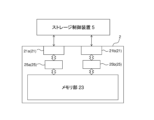
- FIG. 5 is a diagram showing the configuration of the storage.
- FIG. 6 is a diagram showing signal transmission and reception in the initialization operation of the video recording system.
- FIG. 7 is a diagram showing signal transmission and reception during video readout and recording operations.
- FIG. 8 is a flowchart showing the operation of the first information processing device when an abnormality occurs in the recording operation.
- FIG. 9 is a flowchart showing the operation of the second information processing apparatus when an abnormality occurs in the recording operation.
- FIG. 1 is a diagram showing the configuration of a video recording system.
- FIG. 2 is a diagram showing the configuration of the first information processing device.
- FIG. 3 is a diagram showing the configuration of the second information processing device.
- FIG. 10 is a diagram showing the transmission and reception of signals during a video recording operation when an abnormality occurs.
- FIG. 11 is a flowchart showing the operation of the first information processing device when compressed video is the video to be recorded.
- FIG. 12 is a flowchart showing the operation of the second information processing device 4 when compressed video is the video to be recorded.
- FIG. 13 is a diagram showing the transmission and reception of signals in a recording operation when compressed video is the video to be recorded.
- FIG. 14 is a diagram showing an example of transfer information.
- FIG. 15 is a flowchart showing the operation of the first information processing device in recording the recording target video using transfer information.
- FIG. 16 is a flowchart showing the operation of the second information processing device in recording the recording target video using transfer information.
- FIG. 17 is a diagram illustrating transmission and reception of signals during recording of a recording target video using transfer information TI.
- FIG. 18 is a diagram illustrating an example of transfer information after conversion.
- FIG. 19 is a diagram showing the
- video means data including video data and audio data, data including only video data, and data including still image data.
- the video recording system 100 of the present disclosure will be described below with reference to the drawings.
- the video recording system 100 is a system that can generate new video by appropriately editing video by "cutting and pasting.” Specifically, the video recording system 100 generates a new video by inserting, for example, a specific part of the video that was previously acquired and recorded in storage into the video that was acquired from the video output device 1, and Provided to.
- FIG. 1 is a diagram showing the configuration of a video recording system 100.
- the video recording system 100 includes a video output device 1, a storage 2, a first information processing device 3, a second information processing device 4, and a storage control device 5.
- the video output device 1 is a device that outputs video to the outside.
- the video output device 1 is, for example, a video photographing device that includes a camera that photographs a predetermined video, a microphone that acquires audio of the predetermined video, and the like.
- the video output device 1 may be a media server that records a large number of videos.
- the video output by the video output device 1 is, for example, a high-quality video such as an uncompressed 4K video.
- the video recording system 100 may include a plurality of video output devices 1.
- the storage 2 is a storage device that records video.
- the storage 2 is, for example, a solid state drive (SSD) that uses semiconductor nonvolatile memory as a data recording area.
- the storage 2 may be a hard disk drive (HDD).
- the storage 2 has a plurality of access ports 21 for connection with the outside.
- the storage 2 is connected to the storage control device 5 by connecting the plurality of access ports 21 to the storage control device 5 .
- the storage 2 is capable of recording/reading data via each of the plurality of access ports 21. As a result, even if an abnormality occurs in one of the multiple access ports 21 and data cannot be recorded/read, the storage 2 can still record/read data via the other access ports 21. . As a result, the reliability of the storage 2 is improved.
- the storage 2 has two access ports 21a and 21b.
- the number of access ports 21 is not limited to two.
- the number of access ports 21 can be any number greater than or equal to 2, if necessary.
- the storage 2 is located outside the storage control device 5.
- the present invention is not limited to this, and the storage 2 may be placed within the storage control device 5.
- the first information processing device 3 is connected to the video output device 1 and can input video from the video output device 1. Further, the first information processing device 3 is connected to a storage control device 5. The storage control device 5 allocates one of the plurality of access ports 21 of the storage 2 to the first information processing device 3 for data transmission and reception. That is, the first information processing device 3 is capable of transmitting and receiving data to and from the storage 2 via any one of the plurality of access ports 21.
- the first information processing device 3 records the video input from the video output device 1 into the storage 2 via the assigned access port 21.
- the video input from the video output device 1 and recorded in the storage 2 will be referred to as "video to be recorded.”
- the video recorded in the storage 2 can be used, for example, for future video editing.
- the first information processing device 3 edits the video input from the video output device 1 and sends the edited video to an external device 6 (for example, a display).
- an external device 6 for example, a display
- the first information processing device 3 can generate a new video by inserting a specific portion of a past video stored in the storage 2 into the video input from the video output device 1, for example.
- the first information processing device 3 is connected to the second information processing device 4, and is capable of transmitting and receiving data to and from the second information processing device 4. For example, when performing editing to insert a specific part of a past video into a video input from the video output device 1, the first information processing device 3 determines where in the past video the specific part exists. A command to analyze is transmitted to the second information processing device 4. As a response to this command, the first information processing device 3 receives the analysis result (location of a specific portion used for video editing) by the second information processing device 4.
- the first information processing device 3 when the first information processing device 3 is unable to record the recording target video onto the storage 2 and the second information processing device 4 instead records the recording target video onto the storage 2, the first information processing device 3 The information processing device 4 transmits information necessary for recording the video to be recorded in the storage 2.
- the second information processing device 4 is connected to the storage control device 5.
- the storage control device 5 allocates an access port 21 different from that of the first information processing device 3 to the second information processing device 4 for transmitting and receiving data. That is, the second information processing device 4 is enabled by the storage control device 5 to transmit and receive data to and from the storage 2 via an access port 21 different from that of the first information processing device 3.
- the second information processing device 4 reads a desired video from the storage 2 via the assigned access port 21 and executes predetermined processing regarding this video. Specifically, for example, based on a command from the first information processing device 3, the second information processing device 4 analyzes the past video recorded in the storage 2, and the first information processing device 3 To identify where in a past video a specific part used for video editing exists. The second information processing device 4 executes the above video analysis using AI, for example. The second information processing device 4 transmits the video analysis result to the first information processing device 3.
- Video to be recorded can also be recorded in the storage 2 via the access port 21 assigned to the second information processing device 4.
- the second information processing device 4 is connected to the video output device 1 and can input video from the video output device 1.
- the second information processing device 4 can input the same video as the video input to the first information processing device 3 from the video output device 1. Therefore, when recording a video to be recorded in the storage 2 instead of the first information processing device 3, the second information processing device 4 records the same video as the video to be recorded that is input to the first information processing device 3. This same video can be input from the video output device 1 and recorded in the storage 2 as a video to be recorded. Thereby, the second information processing device 4 can record the recording target video (the same video) in the storage 2 without receiving the recording target video from the first information processing device 3.
- the storage control device 5 controls transmission and reception of images and commands between the first information processing device 3 and the second information processing device 4 and the storage 2.
- the storage control device 5 allocates one of the plurality of access ports 21 of the storage 2 to the first information processing device 3 for transmitting and receiving data, and assigns the other one to the second information processing device for transmitting and receiving data. Assign to device 4.
- FIG. 2 is a diagram showing the configuration of the first information processing device 3.
- the first information processing device 3 includes a CPU 31 , a RAM 33 , a storage device 35 , an interface 37 , and a network interface 39 .
- the CPU 31 executes various processes in the first information processing device 3. Specifically, the CPU 31 executes information processing related to video editing, processing related to recording the video input from the video output device 1 into the storage 2, etc. as information processing in the first information processing device 3.
- the CPU 31 executes various processes by executing instructions shown in programs stored in the storage device 35. Note that a part of the processing may be realized by hardware installed in the CPU 31.
- the CPU 31 generates commands for executing various processes.
- the RAM 33 temporarily stores data and the like.
- the commands generated by the CPU 31 are temporarily stored in the RAM 33 (queueing). Further, data transmitted and received between the video output device 1, the storage 2, the second information processing device 4, and the storage control device 5 is also temporarily stored in the RAM 33.
- the storage device 35 is composed of a ROM, a hard disk (HDD), a solid state drive (SSD), and the like.
- the storage device 35 stores programs executed by the CPU 31, settings related to processing of the first information processing device 3, parameters used for the processing, and the like.
- the interface 37 connects the first information processing device 3 and other devices. As shown in FIG. 2, the video output device 1 and the external device 6 are connected to the interface 37.
- the interface 37 is an interface for connecting video-related equipment, such as an interface based on the Serial Digital Interface (SDI) standard, for example.
- SDI Serial Digital Interface
- the network interface 39 connects the first information processing device 3 and other devices via a network such as a WAN or LAN. As shown in FIG. 2, the second information processing device 4 and the storage control device 5 are connected to the network interface 39.
- the network interface 39 allows data to be directly transmitted and received between the RAM 33 of the first information processing device 3 and other device RAMs by remote direct memory access (RDMA). This allows high-speed data transmission and reception between the first information processing device 3 and other devices.
- the network interface 39 is, for example, a Gigabit Ethernet (registered trademark) interface.
- the video output device 1 and the external device 6 may be connected to the network interface 39 instead of the interface 37.
- transmission according to the ST2110 standard of the SMPTE standardization body can be used.
- FIG. 3 is a diagram showing the configuration of the second information processing device 4.
- the second information processing device 4 includes a CPU 41 , a RAM 43 , a storage device 45 , an interface 47 , and a network interface 49 .
- the CPU 41 executes various processes in the second information processing device 4. Specifically, the CPU 41 executes processing related to video analysis using AI and recording the video in the storage 2 instead of the first information processing device 3 as information processing in the second information processing device 4 .
- the CPU 41 executes various processes in the second information processing device 4 by executing instructions shown in programs stored in the storage device 45. The CPU 41 generates a command for executing the above processing.
- a part of the processing in the second information processing device 4 may be realized by hardware installed in the CPU 41.
- AI used for video analysis may be realized by a program stored in the storage device 45 or by hardware installed in the CPU 41.
- the RAM 43 temporarily stores data and the like.
- the commands generated by the CPU 41 are temporarily stored in the RAM 43. Further, data transmitted and received between the video output device 1, the storage 2, the first information processing device 3, and the storage control device 5 is also temporarily stored in the RAM 43.
- the storage device 45 is composed of a ROM, a hard disk (HDD), a solid state drive (SSD), etc.
- the storage device 45 stores programs executed by the CPU 41, settings related to processing of the second information processing device 4, parameters used for the processing, and the like.
- the interface 47 connects the second information processing device 4 and other devices. As shown in FIG. 3, the video output device 1 is connected to the interface 47.
- the interface 47 is an interface for connecting video-related equipment, such as an interface based on the serial digital interface standard, for example.
- the network interface 49 connects the second information processing device 4 and other devices via a network such as a WAN or LAN. As shown in FIG. 2, the first information processing device 3 and the storage control device 5 are connected to the network interface 49.
- the network interface 49 directly transmits and receives data between the RAM 43 of the second information processing device 4 and the RAM of other devices using RDMA.
- the network interface 49 is, for example, a Gigabit Ethernet (registered trademark) interface.
- the video output device 1 may be connected to the network interface 49 instead of the interface 47.
- FIG. 4 is a diagram showing the configuration of the storage control device 5. As shown in FIG.
- the storage control device 5 includes a CPU 51, a RAM 53, a storage device 55, a storage interface 57, and a network interface 59.
- the CPU 51 executes various processes in the storage control device 5.
- the CPU 51 executes various processes in the storage control device 5 by executing instructions shown in programs stored in the storage device 55. Note that a part of the processing in the storage control device 5 may be realized by hardware installed in the CPU 51.
- the RAM 53 temporarily stores data and the like.
- the RAM 53 temporarily stores instructions for the storage 2, data transmitted and received between the first information processing device 3, the second information processing device 4, and the storage 2, and the like.
- the storage device 55 is composed of a ROM, a hard disk (HDD), a solid state drive (SSD), and the like.
- the storage device 55 stores programs executed by the CPU 51, settings related to processing of the storage control device 5, parameters used in the processing, and the like.
- the storage device 55 stores information for associating the first information processing device 3 and the second information processing device 4 with the access port 21 of the storage 2 .
- the storage interface 57 connects the storage control device 5 and the storage 2.
- one storage interface 57 is connected to a plurality of access ports 21 (access ports 21a, 21b) of the storage 2.
- the present invention is not limited to this, and the storage control device 5 may be provided with a plurality of storage interfaces 57, and one storage interface 57 may be connected to one access port 21.
- the storage interface 57 is, for example, a PCIe interface compliant with the PCI express standard of the PCI-SIG standard.
- the storage control device 5 and the storage 2 can transmit and receive data and the like at high speed using a protocol dedicated to non-volatile memory (NVMe (Non-Volatile Memory Express)) using the PCI-Express bus.
- NVMe Non-Volatile Memory Express
- the controller acquires data in the NAND memory using the NAND protocol, replaces it with the PCIe protocol, and transfers it to the host side.
- the DMA controller that directly transfers data to the host side converts and acquires data from NAND memory to SATA protocol, and then converts the data to PCIe protocol and transfers it to the host. Forward. That is, since NVMe processing directly converts the NAND protocol to the PCIe protocol, the data transfer processing speed is high.
- the network interface 59 connects the storage control device 5 and other devices via a network such as a WAN or LAN. As shown in FIG. 4, the first information processing device 3 and the second information processing device 4 are connected to the network interface 59.
- the network interface 59 allows direct data transmission and reception between the RAM 53 of the storage control device 5 and the RAM of other devices using RDMA. Further, the network interface 59 is capable of transmitting and receiving data at high speed with other devices using a protocol (NVMe-oF (NVMe over Fabric)) for communication via a network dedicated to solid state drives.
- the network interface 59 is, for example, a Gigabit Ethernet (registered trademark) interface.
- FIG. 5 is a diagram showing the configuration of the storage 2. As shown in FIG. The storage 2 includes a plurality of access ports 21 and a memory section 23.
- the plurality of access ports 21 connect the storage control device 5 and the storage 2.
- two access ports 21a and 21b are provided.
- Each access port 21 is provided with a controller 25 (controllers 25a, 25b).
- the access port 21a is provided with a controller 25a
- the access port 21b is provided with a controller 25b.
- the controller 25 executes control regarding the storage 2. Specifically, the controller 25 controls recording of data into the memory section 23 and reading of data from the memory section 23 . The controller 25 also performs other necessary processing on the solid state drive, such as wear leveling.
- the memory unit 23 constitutes a data recording area of the storage 2.
- the memory section 23 is composed of a plurality of NAND flash memories.
- the storage 2 may include a buffer memory (not shown) in addition to the memory section 23.
- the buffer memory constitutes a storage area that temporarily stores data from the outside and data to the outside.
- FIG. 6 is a diagram showing the transmission and reception of signals in the port assignment operation.
- the first information processing device 3 transmits a port allocation request to the storage control device 5. Specifically, the CPU 31 of the first information processing device 3 generates a port assignment request and stores it in the RAM 33.
- the port allocation request includes identification information of the access port 21 to be allocated to the first information processing device 3. For example, assume that the first information processing device 3 is assigned the access port 21a. In the following description, the access port 21a will be referred to as the first port 21a.
- the network interfaces 39 and 59 transmit the port assignment request stored in the RAM 33 to the RAM 53.
- the storage control device 5 Upon receiving the above port allocation request, the storage control device 5 executes a process of allocating the first port 21a to the storage control device 5.
- the storage control device 5 uses the identification information of the first information processing device 3 (e.g., IP address) and the identification information of the first port 21a of the storage 2 (e.g., the port of the first port 21a). address) and generates a table that associates them.
- the storage control device 5 can transmit the data to the storage 2 via the first port 21a.
- the storage control device 5 can transmit the data to the first information processing device 3.
- step S2 the storage control device 5 transmits a port allocation request to the storage 2 via the first port 21a.
- the controller 25a that has received this port allocation request executes processing to enable data transmission and reception via the first port 21a.
- step S3 the controller 25a sends a notification that the above processing has been completed (completion notification) to the storage control device 5 via the first port 21a.
- This completion notification is stored in the RAM 53.
- step S4 the network interfaces 39 and 59 transmit the completion notification stored in the RAM 53 to the RAM 33 using RDMA.
- the first information processing device 3 can recognize that the first port 21a has been assigned to the first information processing device 3, and data (video) can now be transmitted and received via the first port 21a.
- the second information processing device 4 transmits a port allocation request to the storage control device 5.
- the port allocation request sent by the second information processing device 4 includes identification information of, for example, the access port 21b, which is the access port 21 that requests the second information processing device 4 to allocate.
- the access port 21b will be referred to as the second port 21b.
- the storage control device 5 which has received the port allocation request from the second information processing device 4, performs port allocation processing by, for example, identifying information of the second information processing device 4 and identifying information of the second port 21b of the storage 2. Generate a table that associates. Thereby, when data is transmitted from the second information processing device 4 to the storage control device 5, the storage control device 5 can transmit the data to the storage 2 via the second port 21b. Further, when data is transmitted from the second port 21b, the storage control device 5 can transmit the data to the second information processing device 4.
- step S6 the storage control device 5 transmits a port allocation request to the storage 2 via the second port 21b.
- the controller 25b that has received this port allocation request executes processing to enable data transmission and reception via the second port 21b.
- step S7 the controller 25b sends a completion notification to the storage control device 5 via the second port 21b.
- This completion notification is stored in the RAM 53.
- step S8 the network interfaces 49 and 59 transmit the completion notification stored in the RAM 53 to the RAM 43 of the second information processing device 4 using RDMA.
- the second information processing device 4 can recognize that the second port 21b has been assigned to the second information processing device 4, and data (video) can now be transmitted and received via the second port 21b.
- FIG. 7 is a diagram showing signal transmission and reception during video readout and recording operations.
- the video read operation by the first information processing device 3 is first started by the first information processing device 3 transmitting a video read command to the first port 21a of the storage 2 in step S11. .
- the CPU 31 of the first information processing device 3 generates a read command and stores it in the RAM 33.
- the read command includes information regarding the video to be read (for example, the recording area in the memory unit 23 where the video is recorded).
- the network interfaces 39 and 59 transmit the read command stored in the RAM 33 of the first information processing device 3 to the RAM 53 of the storage control device 5 using RDMA.
- the CPU 51 of the storage control device 5 determines to transmit the read command received from the first information processing device 3 to the storage 2 via the first port 21a. As a result, the read command stored in the RAM 53 is transmitted to the storage 2 via the first port 21a.
- step S12 the controller 25a that has received the read command transmits the video recorded in the recording area of the memory unit 23 specified in the read command to the first information processing device 3. Specifically, the controller 25a acquires the video from the designated recording area of the memory unit 23, and transmits it to the RAM 53 of the storage control device 5 via the first port 21a and the storage interface 57.
- the CPU 51 determines that the destination of the video received via the first port 21a is the first information processing device 3.
- the network interfaces 39 and 59 transmit the video stored in the RAM 53 to the RAM 33 using RDMA.
- the video readout operation by the second information processing device 4 is similar to the readout operation by the first information processing device 3. Specifically, it is as follows.
- the second information processing device 4 transmits a video read command to the second port 21b of the storage 2.
- the controller 25b that has received the read command transmits the video recorded in the recording area of the memory unit 23 specified in the read command to the second information processing device 4.
- the video recording operation will be explained.
- the first information processing device 3 uses a video input from the video output device 1 as a video to be recorded.
- the CPU 31 inputs the video acquired by the video output device 1 as a video to be recorded, and stores it in the RAM 33.
- the first information processing device 3 transmits a recording command for the video to be recorded to the first port 21a of the storage 2.
- the CPU 31 generates a recording command for the recording target video and stores it in the RAM 33.
- the recording command includes information regarding the recording area of the memory unit 23 where the recording target video is to be recorded.
- the network interfaces 39 and 59 transmit the recording command stored in the RAM 33 to the RAM 53 using RDMA.
- the CPU 51 determines to transmit the recording command received from the first information processing device 3 to the storage 2 via the first port 21a. As a result, the recording command stored in the RAM 53 is transmitted to the storage 2 via the storage interface 57 and the first port 21a.
- the first information processing device 3 transmits the video to be recorded to the first port 21a of the storage 2.
- the network interfaces 39 and 59 transmit the recording target video stored in the RAM 33 of the first information processing device 3 to the RAM 53 of the storage control device 5 using RDMA.
- the CPU 51 determines to transmit the recording target video received from the first information processing device 3 to the storage 2 via the first port 21a.
- the recording target video stored in the RAM 53 is transmitted to the storage 2 via the storage interface 57 and the first port 21a.
- the controller 25a Upon receiving the recording command and the recording target video, the controller 25a records the recording target video in the recording area of the memory unit 23 specified in the recording command. If the recording of the recording target video is successful, the controller 25a transmits a notification to the effect that recording of the recording target video has been completed (completion notification) to the first information processing device 3 (step S17). Specifically, the controller 25a transmits a completion notification to the RAM 53 via the first port 21a and the storage interface 57. The CPU 51 determines that the destination of the completion notification received via the first port 21a is the first information processing device 3. The network interfaces 39 and 59 transmit the completion notification stored in the RAM 53 to the RAM 33 using RDMA.
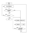
- FIG. 8 is a flowchart showing the operation of the first information processing device 3 when an abnormality occurs in the recording operation.
- FIG. 9 is a flowchart showing the operation of the second information processing device 4 when an abnormality occurs in the recording operation.
- FIG. 10 is a diagram showing the transmission and reception of signals during a video recording operation when an abnormality occurs.
- step S21 a video acquired by the video output device 1 is input to the first information processing device 3 as a video to be recorded.
- the input video to be recorded is stored in the RAM 33 by the CPU 31.
- step S22 the first information processing device 3 attempts to record the recording target video stored in the RAM 33 into the storage 2 via the first port 21a. Specifically, in step S201, the first information processing device 3 transmits a recording command for recording target video to the first port 21a of the storage 2. Next, in step S202, the first information processing device 3 transmits the recording target video stored in the RAM 33 to the storage 2 via the first port 21a.
- a more specific recording operation is the same as that described above with reference to FIG. 7, so a description thereof will be omitted here.
- step S23 As a result of attempting to record the recording target video onto the storage 2, if a message indicating that the recording target video has been completed (that is, a completion notification) is sent (“No” in step S23), the first information processing device 3: Unless an operation to stop the recording operation is performed (as long as step S24 is "No"), steps S21 to S23 described above are repeatedly executed.
- step S23 step S203
- the first information processing device 3 instructs the second information processing device 4 to record the video to be recorded on behalf of the first information processing device 3. command. Further, the first information processing device 3 instructs to reset the first port 21a.
- step S23 If “Yes” in step S23, the process advances to step S25 and step S204, and the first information processing device 3 transmits a reset command to the first port 21a of the storage 2. More details are as follows.
- the CPU 31 generates a reset command and stores it in the RAM 33.
- the network interfaces 39 and 59 transmit the reset command stored in the RAM 33 to the RAM 53 using RDMA.
- the CPU 51 determines to transmit the reset command received from the first information processing device 3 to the first port 21a. As a result, the reset command stored in the RAM 53 is transmitted to the controller 25a via the first port 21a.
- the controller 25a Upon receiving the reset command, the controller 25a executes the reset of the first port 21a.
- the controller 25a stops operating due to some abnormality if the controller 25a is restarted by this reset, it becomes possible to send and receive data via the first port 21a.
- Examples of abnormalities that can be resolved by resetting include an abnormality that occurs while the controller 25a is executing the control program for the first port 21a, and an abnormality that occurs when the buffer memory is full and data cannot be received.
- the first information processing device 3 instructs the second information processing device 4 to record the video to be recorded in the storage 2 instead of the first information processing device 3 (alternative (referred to as a transmission command). More specifically, the CPU 31 generates an alternative transmission command and stores it in the RAM 33. The network interfaces 39 and 49 transmit the alternative transmission command stored in the RAM 33 to the RAM 53 using RDMA.
- the first information processing device 3 transmits the area information to the second information processing device 4.
- the area information is information indicating the recording area of the storage 2 in which an attempt was made to record the recording target video for which recording failed. That is, the area information indicates at which position in the memory unit 23 of the storage 2 the recording target video for which recording has failed is to be recorded.
- the area information is, for example, a logical block address (LBA) of the memory unit 23 in which the video to be recorded is to be recorded.
- LBA logical block address
- the second information processing device 4 executes recording of the recording target video onto the storage 2 in steps S207 to S209.
- the recording operation of the recording target video onto the storage 2 by the second information processing device 4 will be explained later.
- step S28 the first information processing device 3 completes resetting the first port 21a. It is determined whether a notification to the effect that the reset has been completed (referred to as a reset completion notification) has been received. Note that the reset completion notification is generated by the controller 25a and transmitted to the RAM 53 via the first port 21a. Thereafter, the network interfaces 39 and 59 transmit the reset completion notification stored in the RAM 53 to the RAM 33 using RDMA.
- the first information processing device 3 determines that the second information processing device 4 should continue recording the recording target video. If there is a next video to be recorded, the process returns to step S27 (step S206 in FIG. 10), and the first information processing device 3 transmits area information for the next video to be recorded to the second information processing device 4. do. As a result, the second information processing device 4 records the next video to be recorded in place of the first information processing device 3 at the position indicated by the area information of the memory unit 23 of the storage 2 .
- step S210 the first information processing device 3 determines to end the recording of the recording target video by the second information processing device 4.
- the first information processing device 3 issues a command to the second information processing device 4 to end recording of the video to be recorded by the second information processing device 4 (alternative transmission cancellation command). call) and send. More details are as follows.
- the CPU 31 generates an alternative transmission cancellation command and stores it in the RAM 33.
- the network interfaces 39 and 49 transmit the alternative transmission cancellation command stored in the RAM 33 to the RAM 53 using RDMA.
- step S21 the process returns to step S21, and the first information processing device 3 resumes recording the recording target video to the storage 2 via the first port 21a (steps S212 to S214).
- the second information processing device 4 determines whether or not an alternative transmission command has been received from the first information processing device 3 in steps S32 and S205 while executing a predetermined process related to video (step S31).
- step S32 If the alternative transmission command has not been received (“No” in step S32), the second information processing device 4 continues the predetermined process unless an operation to stop the predetermined process is performed (as long as “No” in step S33). continues execution (that is, returns to step S31).
- the second information processing device 4 records the recording target video in the storage 2 instead of the first information processing device 3. Note that while the second information processing device 4 is recording the recording target video, it also executes predetermined processing regarding the video in parallel.
- the area information is transmitted from the first information processing device to the second information processing device 4 in steps S34 and S206.
- step S35 the second information processing device 4 that has received the area information transfers the recording target video to the storage 2 indicated by the area information received from the first information processing device 3 via the second port 21b. is recorded in the recording area of the memory section 23.
- the second information processing device 4 transmits a recording command for the video to be recorded to the second port 21b. More details are as follows.
- the CPU 41 generates a recording command and stores it in the RAM 43. This recording command includes area information received from the first information processing device 3 as information regarding the recording area of the memory section 23 where the recording target video is to be recorded.
- the network interfaces 49 and 59 transmit the recording command stored in the RAM 43 to the RAM 53 using RDMA.
- the CPU 51 determines to transmit the recording command received from the second information processing device 4 to the storage 2 via the second port 21b. As a result, the recording command stored in the RAM 53 is transmitted to the storage 2 via the second port 21b.
- step S208 the second information processing device 4 transmits the video to be recorded to the second port 21b of the storage 2.
- the details are as follows.
- the network interfaces 49 and 59 transmit the recording target video stored in the RAM 43 to the RAM 53 using RDMA.
- the CPU 51 determines to transmit the recording target video received from the second information processing device 4 to the storage 2 via the second port 21b.
- the recording target video stored in the RAM 53 is transmitted to the storage 2 via the storage interface 57 and the second port 21b.
- the controller 25b that has received the recording command and the recording target video records the recording area of the memory unit 23 specified in the recording command, that is, the recording area of the memory unit 23 indicated by the area information received from the first information processing device 3. Record the video to be recorded in the area. If the recording target video has been successfully recorded, the controller 25b transmits a completion notification to the second information processing device 4 in step S209.
- the details are as follows.
- the controller 25b sends the completion notification to the RAM 53 via the second port 21b and the storage interface 57.
- the CPU 51 determines that the destination of the completion notification received via the second port 21b is the second information processing device 4.
- the network interfaces 49 and 59 transmit the completion notification stored in the RAM 53 to the RAM 43 using RDMA.
- step S36 the second information processing device 4 determines to continue recording the recording target video.
- step S34, step S206 the second information processing device 4 executes the above step S35 (steps S207 to S209) to The same video as the next recording target video input and stored in the RAM 43 is recorded in the recording area indicated by the area information of the memory section 23 of the storage 2 via the second port 21b.
- step S36 determines to end the recording of the recording target video, and performs the main function of the second information processing device 4. Only predetermined processing regarding a certain video is executed (that is, the process returns to step S31).
- the second information processing device 4 when an abnormality occurs in the first port 21a assigned to the first information processing device 3, the second information processing device 4 , records the video to be recorded in the storage 2 instead of the first information processing device 3 .
- the second information processing device 4 to which the second port 21b is assigned will be able to 1
- the video to be recorded can be recorded in the storage 2 instead of the information processing device 3.
- the second information processing device 4 instead of the first information processing device 3 records the video to be recorded in the storage 2
- area information is transferred from the first information processing device 3 to the second information processing device 4. is transmitted, and the second information processing device 4 records the video to be recorded in the recording area indicated by this area information.
- the second information processing device 4 can record the recording target video in the same recording area of the memory unit 23 where the first information processing device was trying to record the recording target video.
- the device when a device other than the second information processing device 4 (for example, the first information processing device 3) reads the video recorded in the storage 2 by the second information processing device 4, the device , it is possible to prevent a video from the wrong recording area (that is, a video different from the video to be read) from being read.
- the wrong recording area that is, a video different from the video to be read
- the second information processing device 4 on behalf of the first information processing device 3, performs the recording target video from the time when the substitute transmission command is received until the time when the substitute transmission cancellation command is received. is recorded in storage 2. That is, the second information processing device 4 records the video to be recorded in the storage 2 until the reset of the first port 21a where the abnormality has occurred is started and the first port is restored. In other words, the second information processing device 4 executes recording of the recording target video onto the storage 2 only during the period when an abnormality occurs in the first port 21a.
- the second information processing device 4 does not unnecessarily record the video to be recorded in the storage 2, so that the second information processing device 4 can devote time to only executing predetermined processing, which is the main function of the second information processing device 4. Can be secured as much as possible.
- Modification example 1 The following case is assumed in Modification 1.
- the first information processing device records the input video to be recorded in the storage 2 without performing compression processing.
- the first information processing device 3 compresses the recording target video in uncompressed format and transmits it to the second information processing device 4, and the second information processing device 4 , the compressed video to be recorded is recorded in the storage 2.
- FIGS. 11 to 13 FIG. 11 is a flowchart showing the operation of the first information processing device 3.
- FIG. 12 is a flowchart showing the operation of the second information processing device 4.
- FIG. 13 is a diagram showing signal transmission and reception.
- the first information processing device 3 compresses the video that is input from the video output device 1 and is intended to be the video to be recorded, to generate a compressed video to be the video to be recorded.
- the first information processing device 3 converts an uncompressed video that is intended to be a recording target video into a compressed format video, or lowers the bit rate, resolution, frame rate, etc. of the video that is intended to be a recording target video.
- Compressed video can be generated using methods such as .
- step S48 After generating the compressed video, in step S48 and steps S306 to S307, the first information processing device 3 transmits the generated compressed video together with area information to the second information processing device 4 as a video to be recorded.
- step S55 the second information processing device 4, which has received the area information and the compressed video (step S54), uses the compressed video as the video to be recorded, and uses the memory unit 2 of the storage 2 indicated in the received area information. Record in the recording area.
- processing contents in steps S41 to S46 and steps S49 to S50 in FIG. 11 are the same as the processing contents in steps S21 to S26 and steps S28 to S29 in FIG. 8, respectively, so a detailed explanation will be omitted.
- the processing contents in steps S51 to S53 and step S56 in FIG. 12 are the same as the processing contents in steps S31 to S33 and step S36 in FIG. 9, respectively, so a detailed explanation will be omitted.
- the processing contents in steps S301 to S305 and steps S308 to S315 in FIG. 13 are the same as the processing contents in steps S201 to S205 and steps S207 to S214 in FIG. 10, respectively, so a detailed explanation will be omitted.
- the first information processing device 3 compresses the video input from the video output device 1 to generate a compressed video
- the second information processing device 4 records the compressed video in the storage 2 as a recording target video.
- the second information processing device 4 can record the recording target video onto the storage 2 in a short time.
- the second information processing device 4 when the second information processing device 4 records the recording target video in the storage 2 instead of the first information processing device 3, the second information processing device 4 sets the amount of processing resources used for predetermined processing regarding the video to the normal amount. (That is, when recording of the recording target video to the storage 2 is not executed) may be decreased.
- the "processing resource amount” refers to, for example, the ratio of the time used by the CPU 41 of the second information processing device 4 for predetermined processing to the time used for recording the recording target video, Refers to the amount of RAM 43 used for this purpose.
- the recording of the recording target video to the storage 2 may be performed based on the transfer information TI, which is the area information plus additional information, instead of the area information.
- the transfer information TI is information that includes information regarding the transfer source of the video to be recorded (referred to as transfer source information) in addition to the area information described above.
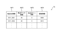
- the transfer information TI includes transfer source information INF1, transfer size information INF2, transfer destination port information INF3, and area information INF4. Note that the transfer information TI shown in FIG. 14 is used when the video to be recorded is composed of a plurality of unit data and the recording of the video to be recorded is performed in units of this unit data.
- FIG. 14 is a diagram showing an example of transfer information TI.
- the transfer source information INF1 is information regarding the transfer source of the video to be recorded, and is information indicating the location of the video to be recorded. As shown in FIG. 14, the transfer source information INF1 is expressed, for example, in the format of "device identification name where the video to be recorded exists_location of the video to be recorded in the RAM in the device". For example, the transfer source information INF1 expressed as "0011_0001" indicates that the unit data of the video to be recorded is recorded at the address "0001" of the RAM 33 of the first information processing device 3 (device identification name: 0011). .
- the transfer size information INF2 represents the size of unit data that is the unit of transmission and reception of the video to be recorded.
- the transfer size information INF2 expressed as "4K" indicates that the size of the unit data is 4 kilobytes.
- the transfer destination port information INF3 indicates through which access port 21 of the storage 2 the video to be recorded is recorded.
- the transfer destination port information INF3 expressed as "0" indicates that the recording target video is recorded in the memory unit 23 of the storage 2 via the first port 21a.
- the area information INF4 is the same information as the area information explained above. That is, the area information INF4 indicates the recording area of the memory unit 23 of the storage 2 where the recording target video is to be recorded. For example, area information INF4 expressed as “0008” indicates that the unit data of the video to be recorded is recorded at address “0008” of the memory unit 23.
- the first line of the transfer information TI shown in FIG. This indicates that the information processing device 3 records at address “0008” of the memory unit 23 of the storage 2 via the first port 21a.
- FIG. 15 is a flowchart showing the operation of the first information processing device 3.
- FIG. 16 is a flowchart showing the operation of the second information processing device 4.
- FIG. 17 is a diagram showing transmission and reception of signals.
- step S61 in FIG. 15 After inputting the video to be recorded from the video output device 1 and storing it in the RAM 33 (step S61 in FIG. 15), the CPU 31 of the first information processing device 3 generates transfer information TI in step S62 in FIG. Remember.
- the first information processing device 3 After generating the transfer information TI, the first information processing device 3 records the recording target video based on the generated transfer information TI in step S63 of FIG. 15 (steps S401 to S403 and steps S412 to S414 of FIG. 17). Execute.
- the controller 25a that has acquired (the unit data of) the recording target video records the acquired recording target video in the recording area (address) of the memory unit 23 indicated by the area information INF4 of the transfer information TI. If the recording target video has been successfully recorded, the controller 25a transmits a completion notification to the first information processing device 3 (step S414). On the other hand, if recording of the recording target video fails, an error notification is sent to the first information processing device 3 (step S403).
- the first line of the transfer information TI shown in FIG. 14 is recorded at the address "0002" of the RAM 43 as shown in the first line of the changed transfer information TIa shown in FIG. is converted to indicate that the second information processing device 4 records the unit data of the video to be recorded having a size of Ru.
- the first information processing device 3 After converting the transfer information TI into transfer information TIa (step S68), the first information processing device 3 transmits the transfer information TIa to the second information processing device 4 (step S69).
- the second information processing device 4 stores the received converted transfer information TIa in the RAM 43.
- the second information processing device 4 After receiving the transfer information TIa (step S84), the second information processing device 4 executes recording of the recording target video based on the transfer information TIa (step S85).
- step S407 the second information processing device 4 transmits the transfer information TIa stored in the RAM 43 to the storage 2 via the second port 21b along with the recording command.
- the controller 25b which has received the recording command and the converted transfer information TIa, sends (the unit of) the video to be recorded stored at the address of the RAM 43 indicated in the transfer source information INF1 of the transfer information TIa via the storage control device 5. data) (step S408).
- the controller 25a records the acquired video to be recorded in the recording area (address) of the memory unit 23 indicated by the area information INF4 of the transfer information TIa. If the recording target video has been successfully recorded, the controller 25b transmits a completion notification to the second information processing device 4 (step S409).
- the recording of the video to be recorded in the storage is performed based on the transfer information TI, TIa that includes at least the area information INF4 and the transfer source information INF1 regarding the transfer source of the video to be recorded.
- a recording target video existing at an appropriate position in the first information processing device 3 or the second information processing device 4 can be recorded in an appropriate recording area of the storage 2.
- the storage control device 5a may have a plurality of network interfaces (network interfaces 59a, 59b).
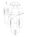
- FIG. 19 is a diagram showing the configuration of a video recording system 100a according to modification 4.
- the first information processing device 3 is connected to the network interface 59a (referred to as a first network interface 59a).
- the first port 21a is assigned to the first network interface 59a for transmitting and receiving data to and from the storage 2.
- the first information processing device 3 and the second information processing device 4 are connected to the network interface 59b (referred to as a second network interface 59b).
- a second port 21b is assigned to the second network interface 59b for transmitting and receiving data to and from the storage 2.
- the network interfaces 59a and 59b are, for example, network switches.
- the video to be recorded by the first information processing device 3 is transmitted via the first network interface 59a and the first port 21a, or via the second network interface 59b and the second port 21b. , can be recorded in storage 2.
- the video to be recorded is transferred from the first information processing device 3 to the storage 2 via the first network interface 59a and the first port 21a. (first mode).
- the video to be recorded is transmitted to the storage 2 via the second network interface 59b and the second port 21b (second mode). That is, the video to be recorded is transmitted to the storage 2 via different network addresses in normal and abnormal times.
- the video to be recorded is recorded in the first mode in the storage 2 via the first network interface 59a and the first port 21a, and in the storage 2 via the second network interface 59b and the second port 21b.
- the data is recorded in the storage 2 in a switchable manner between the second recording mode and the second recording mode.
- the network interfaces 59a, 59b for transmitting the recording target video are switched, or the network If an abnormality occurs in either of the interfaces 59a, 59b, the destination access ports 21a, 21b to which the video to be recorded is transmitted are switched. This makes it possible to build a system that is resistant to abnormalities.
- the second information processing device 4 may be connected to the first network interface 59a. Furthermore, both the first port 21a and the second port 21b may be assigned to each network interface 59a, 59b. In this case, each network interface 59a, 59b may be able to select which access port 21a, 21b is used to transmit and receive data.
- the video recording system of the present disclosure includes a video output device, a storage, a first information processing device, and a second information processing device.
- the video output device outputs video.
- the storage has multiple access ports.
- the first information processing device is connected to the video output device, is assigned a first port among the plurality of access ports of the storage for transmitting and receiving data, and transmits the recording target video input from the video output device to the first port. Record to storage via.
- the second information processing device is assigned a second port among the plurality of access ports of the storage for transmitting and receiving data, and executes predetermined processing regarding video.
- the first information processing device when an abnormality occurs in the first port of the storage, the first information processing device sends area information indicating the recording area of the storage where the recording target video is to be recorded to the second information processing device. Send.
- the second information processing device records the video to be recorded in the recording area of the storage indicated by the area information received from the first information processing device via the second port.
- the first port when an abnormality occurs in the first port of the storage, the first port may be reset. In this case, the recording of the recording target video onto the storage by the second information processing device may be performed from when the reset of the first port is started until the first port is restored.
- the second information processing device does not unnecessarily record the video to be recorded in the storage, so that it is possible to secure the maximum amount of time that can be devoted to only executing predetermined processing.
- the second information processing device is connected to the video output device and outputs the same video as the recording target video input to the first information processing device. It may also be input from the device. In this case, the second information processing device may record the same video input from the video output device in the storage as the recording target video. In this video recording system, the second information processing device can record the same video as the recording target video in the storage as the recording target video without receiving the recording target video from the first information processing device.
- the first information processing device may generate the recording target video by compressing the video input from the video output device.
- the video to be recorded can be recorded in the storage 2 in a short time.
- the second information processing device when the second information processing device records the recording target video in the storage, the second information processing device increases the amount of processing resources used for the predetermined processing compared to normal times. May be decreased. In this video recording system, since the second information processing device can use more processing resources for recording the video to be recorded, it is possible to record the video to be recorded at high speed.
- the first information processing device, the second information processing device, and the storage may be capable of transmitting and receiving data using a protocol dedicated to nonvolatile memory using a PCI-Express bus. Thereby, recording of the recording target video can be executed at high speed.
- Another video recording system of the present disclosure includes a video output device, a storage, a first information processing device, and a storage control device.
- the video output device outputs video.
- the storage has multiple access ports.
- the first information processing device is connected to a video output device.
- a storage and a first information processing device are connected to the storage control device.
- the storage control device allocates a first port among the plurality of access ports of the storage for transmitting and receiving data, a first network interface to which the first information processing device is connected, and a first port among the plurality of access ports of the storage. and a second network interface to which two ports are assigned for transmitting and receiving data and to which the first information processing device is connected.
- the recording target video input by the first information processing device from the video output device is recorded in the storage via the first network interface and the first port
- the second mode is recorded in the storage via the first network interface and the first port.
- a second mode in which the data is recorded in the storage via the second port.
- the present disclosure is applicable to a video recording system that records video from a video output device in storage.
- Video recording system 1 Video output device 2: Storage 21: Access port 21a: First port (access port) 21b: 2nd port (access port) 23: Memory section 25, 25a, 25b: Controller 3: First information processing device 31: CPU 33: RAM 35: Storage device 37: Interface 39: Network interface 4: Second information processing device 41: CPU 43: RAM 45: Storage device 47: Interface 49: Network interface 5: Storage control device 51: CPU 53: RAM 55: Storage device 57: Storage interface 59: Network interface 59a: First network interface 59b: Second network interface 6: External device INF1: Transfer source information INF2: Transfer size information INF3: Transfer destination port information INF4: Area information TI , TIa: Transfer information
Abstract
In the present invention, when an abnormality occurs in a storage port, a different port is used so that video is recorded without interruption. A video recording system (100) is provided with: a video output device (1) for outputting video; storage (2) having a plurality of access ports; a first information processing device (3) connected to the video output device (1) and assigned to a first port (21a) of the storage (2) for recording a video to be recorded to the storage (2) via the first port (21a); and a second information processing device (4) assigned to a second port (21b) of the storage (2) for executing a predetermined processing related to video. If an abnormality occurs in the first port (21a), the first information processing device (3) transmits region information to the second information processing device (4), and the second information processing device (4) records the video to be recorded via the second port (21b) to a recording region of the storage (2) indicated in the region information.
Description
本開示は、映像出力装置からの映像をストレージに記録する映像記録システムに関する。
The present disclosure relates to a video recording system that records video from a video output device in storage.
カメラ等の映像出力装置が出力した映像を入力し、当該映像を外部のストレージに記録するシステムが知られている。外部のストレージに記録された映像は、例えば、将来の再生、又は、映像編集に用いられる。
A system is known that inputs video output from a video output device such as a camera and records the video in external storage. Videos recorded in external storage are used, for example, for future playback or video editing.
一方、データをメモリに記録する際に、主のメモリコントローラに故障等が発生してデータをメモリに記録できないときに、主のメモリコントローラに代わってバックアップのメモリコントローラが当該データをメモリに記録する技術が知られている(例えば、特許文献1参照)。
On the other hand, when recording data in memory, if a failure occurs in the main memory controller and the data cannot be recorded in memory, a backup memory controller records the data in memory instead of the main memory controller. Techniques are known (for example, see Patent Document 1).
映像を外部のストレージに記録するシステムは、映像出力装置から入力した映像をストレージに記録することを担当する映像記録装置を有する。この映像記録装置は、ストレージのポートを割り当てられ、このポートを介してストレージに映像を記録する。このシステムにおいて、上記ポートの異常により、映像記録装置が、ストレージに映像を記録できなくなることがある。この結果、映像出力装置から入力した映像のストレージへの記録が途切れて、将来の再生又は映像編集に用いる映像を記録できないことがある。
A system for recording video onto an external storage has a video recording device that is in charge of recording video input from a video output device onto the storage. This video recording device is assigned a storage port and records video on the storage via this port. In this system, the video recording device may become unable to record video on the storage due to an abnormality in the port. As a result, recording of the video input from the video output device to the storage may be interrupted, making it impossible to record video for future playback or video editing.
本開示は、映像出力装置から出力された映像をストレージに記録している場合に、ストレージのポートに異常が生じたとき、別のポートを利用して、映像を途切れなく記録することを目的とする。
The purpose of the present disclosure is to use another port to record the video without interruption when an abnormality occurs in the storage port when video output from a video output device is being recorded in the storage. do.
本開示の映像記録システムは、映像出力装置と、ストレージと、第1情報処理装置と、第2情報処理装置と、を備える。
映像出力装置は、映像を出力する。
ストレージは、複数のアクセスポートを有する。
第1情報処理装置は、映像出力装置に接続され、ストレージの複数のアクセスポートのうち第1ポートをデータの送受信のために割り当てられ、映像出力装置から入力した記録対象映像を、第1ポートを介してストレージに記録する。
第2情報処理装置は、ストレージの複数のアクセスポートのうち第2ポートをデータの送受信ために割り当てられ、映像に関する所定の処理を実行する。
上記の画像記録システムにおいて、ストレージの第1ポートに異常が発生した場合、第1情報処理装置は、記録対象映像を記録しようとしたストレージの記録領域を示す領域情報を、第2情報処理装置に送信する。
第2情報処理装置は、第2ポートを介して、記録対象映像を、第1情報処理装置から受信した領域情報に示されたストレージの記録領域に記録する。 The video recording system of the present disclosure includes a video output device, a storage, a first information processing device, and a second information processing device.
The video output device outputs video.
The storage has multiple access ports.
The first information processing device is connected to the video output device, is assigned a first port among the plurality of access ports of the storage for transmitting and receiving data, and transmits the recording target video input from the video output device to the first port. Record to storage via.
The second information processing device is assigned a second port among the plurality of access ports of the storage for transmitting and receiving data, and executes predetermined processing regarding video.
In the above image recording system, when an abnormality occurs in the first port of the storage, the first information processing device sends area information indicating the recording area of the storage where the recording target video is to be recorded to the second information processing device. Send.
The second information processing device records the video to be recorded in the recording area of the storage indicated by the area information received from the first information processing device via the second port.
本開示の映像記録システムでは、第1情報処理装置に割り当てられた第1ポートに異常が発生したときに、第1情報処理装置に代わって、ストレージの他のポート(第2ポート)を割り当てられた第2情報処理装置が、記録対象映像をストレージに記録している。これにより、記録対象映像を途切れなく記録できる。
In the video recording system of the present disclosure, when an abnormality occurs in the first port assigned to the first information processing device, another port (second port) of the storage is assigned in place of the first information processing device. The second information processing device records the video to be recorded in the storage. This allows the video to be recorded to be recorded without interruption.
以下、適宜図面を参照しながら、実施の形態を詳細に説明する。但し、必要以上に詳細な説明は省略する場合がある。例えば、既によく知られた事項の詳細説明や実質的に同一の構成に対する重複説明を省略する場合がある。これは、以下の説明が不必要に冗長になるのを避け、当業者の理解を容易にするためである。なお、発明者は、当業者が本開示を十分に理解するために添付図面及び以下の説明を提供するのであって、これらによって特許請求の範囲に記載の主題を限定することを意図するものではない。
Hereinafter, embodiments will be described in detail with reference to the drawings as appropriate. However, more detailed explanation than necessary may be omitted. For example, detailed explanations of well-known matters or redundant explanations of substantially the same configurations may be omitted. This is to avoid unnecessary redundancy in the following description and to facilitate understanding by those skilled in the art. The inventors have provided the accompanying drawings and the following description in order for those skilled in the art to fully understand the present disclosure, and they are not intended to limit the subject matter recited in the claims. do not have.
本開示において、「映像」は、動画データと音声データとを含むデータ、動画データのみを含むデータ、静止画データを含むデータを意味する。
In the present disclosure, "video" means data including video data and audio data, data including only video data, and data including still image data.
[1.映像記録システム]
以下、図面を参照しながら、本開示の映像記録システム100を説明する。映像記録システム100は、映像を適宜「切り貼り」等して編集することで、新たな映像を生成可能なシステムである。具体的には、映像記録システム100は、例えば、映像出力装置1から取得した映像に、過去に取得してストレージに記録した映像の特定の部分を挿入することで新たな映像を生成し、外部に提供する。 [1. Video recording system]
Thevideo recording system 100 of the present disclosure will be described below with reference to the drawings. The video recording system 100 is a system that can generate new video by appropriately editing video by "cutting and pasting." Specifically, the video recording system 100 generates a new video by inserting, for example, a specific part of the video that was previously acquired and recorded in storage into the video that was acquired from the video output device 1, and Provided to.
以下、図面を参照しながら、本開示の映像記録システム100を説明する。映像記録システム100は、映像を適宜「切り貼り」等して編集することで、新たな映像を生成可能なシステムである。具体的には、映像記録システム100は、例えば、映像出力装置1から取得した映像に、過去に取得してストレージに記録した映像の特定の部分を挿入することで新たな映像を生成し、外部に提供する。 [1. Video recording system]
The
以下、図1を用いて、映像記録システム100の構成を説明する。図1は、映像記録システム100の構成を示す図である。映像記録システム100は、映像出力装置1と、ストレージ2と、第1情報処理装置3と、第2情報処理装置4と、ストレージ制御装置5と、を備える。
Hereinafter, the configuration of the video recording system 100 will be explained using FIG. 1. FIG. 1 is a diagram showing the configuration of a video recording system 100. The video recording system 100 includes a video output device 1, a storage 2, a first information processing device 3, a second information processing device 4, and a storage control device 5.
映像出力装置1は、映像を外部に出力する装置である。映像出力装置1は、例えば、所定の映像を撮影するカメラ、当該所定の映像の音声を取得するマイク、などを備える映像撮影装置である。その他、映像出力装置1は、多数の映像を記録したメディアサーバであってもよい。映像出力装置1により出力される映像は、例えば、非圧縮形式の4K映像などの高画質映像である。
The video output device 1 is a device that outputs video to the outside. The video output device 1 is, for example, a video photographing device that includes a camera that photographs a predetermined video, a microphone that acquires audio of the predetermined video, and the like. Alternatively, the video output device 1 may be a media server that records a large number of videos. The video output by the video output device 1 is, for example, a high-quality video such as an uncompressed 4K video.
なお、図1に示す例では、映像出力装置1は1つしか設けられていないが、これに限られない。映像記録システム100は、複数の映像出力装置1を備えてもよい。
Note that in the example shown in FIG. 1, only one video output device 1 is provided, but the invention is not limited to this. The video recording system 100 may include a plurality of video output devices 1.
ストレージ2は、映像を記録する記憶装置である。ストレージ2は、例えば、半導体の不揮発メモリをデータの記録領域とするソリッド・ステート・ドライブ(SSD)である。その他、ストレージ2は、ハードディスクドライブ(HDD)であってもよい。ストレージ2は、外部との接続のための複数のアクセスポート21を有している。複数のアクセスポート21がストレージ制御装置5に接続されることで、ストレージ2は、ストレージ制御装置5に接続されている。
The storage 2 is a storage device that records video. The storage 2 is, for example, a solid state drive (SSD) that uses semiconductor nonvolatile memory as a data recording area. Alternatively, the storage 2 may be a hard disk drive (HDD). The storage 2 has a plurality of access ports 21 for connection with the outside. The storage 2 is connected to the storage control device 5 by connecting the plurality of access ports 21 to the storage control device 5 .
ストレージ2は、複数のアクセスポート21のそれぞれを介して、データの記録/読み出しが可能である。これにより、複数のアクセスポート21のいずれかに異常が発生し、データの記録/読み出しができなくなっても、ストレージ2は、他のアクセスポート21を介して、データの記録/読み出しが可能となる。その結果、ストレージ2の信頼性が向上する。
The storage 2 is capable of recording/reading data via each of the plurality of access ports 21. As a result, even if an abnormality occurs in one of the multiple access ports 21 and data cannot be recorded/read, the storage 2 can still record/read data via the other access ports 21. . As a result, the reliability of the storage 2 is improved.
なお、図1に示す例では、ストレージ2は、2つのアクセスポート21a、21bを有している。しかし、アクセスポート21の数は2に限られない。アクセスポート21の数は、必要に応じて、2以上の任意の数とできる。
Note that in the example shown in FIG. 1, the storage 2 has two access ports 21a and 21b. However, the number of access ports 21 is not limited to two. The number of access ports 21 can be any number greater than or equal to 2, if necessary.
また、図1に示す例では、ストレージ2は、ストレージ制御装置5の外部に配置されている。しかし、これに限られず、ストレージ2は、ストレージ制御装置5内に配置されてもよい。
Furthermore, in the example shown in FIG. 1, the storage 2 is located outside the storage control device 5. However, the present invention is not limited to this, and the storage 2 may be placed within the storage control device 5.
第1情報処理装置3は、映像出力装置1と接続され、映像出力装置1から映像を入力可能となっている。また、第1情報処理装置3は、ストレージ制御装置5と接続されている。ストレージ制御装置5は、ストレージ2の複数のアクセスポート21のうちいずれかを、データの送受信のために第1情報処理装置3に対して割り当てる。すなわち、複数のアクセスポート21のうちいずれかを介して、第1情報処理装置3は、ストレージ2とデータ送受信可能となっている。
The first information processing device 3 is connected to the video output device 1 and can input video from the video output device 1. Further, the first information processing device 3 is connected to a storage control device 5. The storage control device 5 allocates one of the plurality of access ports 21 of the storage 2 to the first information processing device 3 for data transmission and reception. That is, the first information processing device 3 is capable of transmitting and receiving data to and from the storage 2 via any one of the plurality of access ports 21.
第1情報処理装置3は、映像出力装置1から入力した映像を、割り当てられたアクセスポート21を介して、ストレージ2に記録する。以下の説明では、映像出力装置1から入力され、ストレージ2に記録する映像を「記録対象映像」と呼ぶ。ストレージ2に記録された映像は、例えば、将来の映像編集のために用いることができる。
The first information processing device 3 records the video input from the video output device 1 into the storage 2 via the assigned access port 21. In the following description, the video input from the video output device 1 and recorded in the storage 2 will be referred to as "video to be recorded." The video recorded in the storage 2 can be used, for example, for future video editing.
第1情報処理装置3は、映像出力装置1から入力した映像を編集し、編集後の映像を外部装置6(例えば、ディスプレイなど)に送出する。第1情報処理装置3は、映像の編集として、例えば、映像出力装置1から入力した映像に、ストレージ2に記憶された過去の映像の特定の部分を挿入して新たな映像を生成できる。
The first information processing device 3 edits the video input from the video output device 1 and sends the edited video to an external device 6 (for example, a display). As video editing, the first information processing device 3 can generate a new video by inserting a specific portion of a past video stored in the storage 2 into the video input from the video output device 1, for example.
第1情報処理装置3は、第2情報処理装置4と接続され、第2情報処理装置4との間でデータの送受信が可能となっている。例えば、映像出力装置1から入力した映像に過去の映像の特定の部分を挿入する編集を行う場合に、第1情報処理装置3は、当該特定の部分が過去の映像のどの箇所に存在するかを解析する指令を、第2情報処理装置4に送信する。この指令の応答として、第1情報処理装置3は、第2情報処理装置4による解析結果(映像の編集に用いる特定の部分の存在箇所)を受信する。
The first information processing device 3 is connected to the second information processing device 4, and is capable of transmitting and receiving data to and from the second information processing device 4. For example, when performing editing to insert a specific part of a past video into a video input from the video output device 1, the first information processing device 3 determines where in the past video the specific part exists. A command to analyze is transmitted to the second information processing device 4. As a response to this command, the first information processing device 3 receives the analysis result (location of a specific portion used for video editing) by the second information processing device 4.
また、第1情報処理装置3により記録対象映像をストレージ2に記録できず、第2情報処理装置4が代わって記録対象映像をストレージ2に記録する場合、第1情報処理装置3は、第2情報処理装置4が記録対象映像をストレージ2に記録するために必要な情報を送信する。
Further, when the first information processing device 3 is unable to record the recording target video onto the storage 2 and the second information processing device 4 instead records the recording target video onto the storage 2, the first information processing device 3 The information processing device 4 transmits information necessary for recording the video to be recorded in the storage 2.
第2情報処理装置4は、ストレージ制御装置5に接続されている。ストレージ制御装置5は、第1情報処理装置3とは異なるアクセスポート21を、データの送受信のために第2情報処理装置4に対して割り当てる。すなわち、第2情報処理装置4は、ストレージ制御装置5により、第1情報処理装置3とは異なるアクセスポート21を介して、ストレージ2とデータ送受信可能となっている。
The second information processing device 4 is connected to the storage control device 5. The storage control device 5 allocates an access port 21 different from that of the first information processing device 3 to the second information processing device 4 for transmitting and receiving data. That is, the second information processing device 4 is enabled by the storage control device 5 to transmit and receive data to and from the storage 2 via an access port 21 different from that of the first information processing device 3.
第2情報処理装置4は、割り当てられたアクセスポート21を介して、ストレージ2から所望の映像を読み出し、この映像に関する所定の処理を実行する。具体的には、例えば、第1情報処理装置3からの指令に基づいて、第2情報処理装置4は、ストレージ2に記録されている過去の映像を解析して、第1情報処理装置3が映像の編集に用いる特定の部分が過去の映像のどの箇所に存在するかを特定する。第2情報処理装置4は、例えば、AIにより上記の映像解析を実行する。第2情報処理装置4は、映像の解析結果を、第1情報処理装置3に送信する。
The second information processing device 4 reads a desired video from the storage 2 via the assigned access port 21 and executes predetermined processing regarding this video. Specifically, for example, based on a command from the first information processing device 3, the second information processing device 4 analyzes the past video recorded in the storage 2, and the first information processing device 3 To identify where in a past video a specific part used for video editing exists. The second information processing device 4 executes the above video analysis using AI, for example. The second information processing device 4 transmits the video analysis result to the first information processing device 3.
また、第1情報処理装置3に割り当てられたアクセスポート21に異常が発生し記録対象映像をストレージ2に記録できない場合に、第2情報処理装置4は、第1情報処理装置3に代わって、第2情報処理装置4に割り当てられたアクセスポート21を介して、記録対象映像をストレージ2に記録することもできる。
In addition, when an abnormality occurs in the access port 21 assigned to the first information processing device 3 and the video to be recorded cannot be recorded in the storage 2, the second information processing device 4, in place of the first information processing device 3, Video to be recorded can also be recorded in the storage 2 via the access port 21 assigned to the second information processing device 4.
第2情報処理装置4は、映像出力装置1と接続され、映像出力装置1から映像を入力可能となっている。第2情報処理装置4は、第1情報処理装置3に入力された映像と同一の映像を、映像出力装置1から入力できる。このため、第1情報処理装置3に代わって記録対象映像をストレージ2に記録する場合、第2情報処理装置4は、第1情報処理装置3に入力されている記録対象映像と同一の映像を映像出力装置1から入力し、この同一の映像を記録対象映像としてストレージ2に記録できる。これにより、第2情報処理装置4は、記録対象映像を第1情報処理装置3から受信することなく、記録対象映像(と同一の映像)をストレージ2に記録できる。
The second information processing device 4 is connected to the video output device 1 and can input video from the video output device 1. The second information processing device 4 can input the same video as the video input to the first information processing device 3 from the video output device 1. Therefore, when recording a video to be recorded in the storage 2 instead of the first information processing device 3, the second information processing device 4 records the same video as the video to be recorded that is input to the first information processing device 3. This same video can be input from the video output device 1 and recorded in the storage 2 as a video to be recorded. Thereby, the second information processing device 4 can record the recording target video (the same video) in the storage 2 without receiving the recording target video from the first information processing device 3.
ストレージ制御装置5は、第1情報処理装置3及び第2情報処理装置4とストレージ2との間の映像及び指令の送受信を制御する。ストレージ制御装置5は、ストレージ2の複数のアクセスポート21のうちの1つを第1情報処理装置3にデータの送受信のために割り当て、他の1つをデータの送受信のために第2情報処理装置4に割り当てる。
The storage control device 5 controls transmission and reception of images and commands between the first information processing device 3 and the second information processing device 4 and the storage 2. The storage control device 5 allocates one of the plurality of access ports 21 of the storage 2 to the first information processing device 3 for transmitting and receiving data, and assigns the other one to the second information processing device for transmitting and receiving data. Assign to device 4.
[2.第1情報処理装置]
図2を用いて、第1情報処理装置3の構成を説明する。図2は、第1情報処理装置3の構成を示す図である。第1情報処理装置3は、CPU31と、RAM33と、記憶装置35と、インタフェース37と、ネットワークインタフェース39と、を有する。 [2. First information processing device]
The configuration of the firstinformation processing device 3 will be explained using FIG. 2. FIG. 2 is a diagram showing the configuration of the first information processing device 3. As shown in FIG. The first information processing device 3 includes a CPU 31 , a RAM 33 , a storage device 35 , an interface 37 , and a network interface 39 .
図2を用いて、第1情報処理装置3の構成を説明する。図2は、第1情報処理装置3の構成を示す図である。第1情報処理装置3は、CPU31と、RAM33と、記憶装置35と、インタフェース37と、ネットワークインタフェース39と、を有する。 [2. First information processing device]
The configuration of the first
CPU31は、第1情報処理装置3における各種処理を実行する。具体的には、CPU31は、映像編集に関する情報処理、映像出力装置1から入力した映像のストレージ2への記録に関する処理、等を第1情報処理装置3における情報処理として実行する。CPU31は、記憶装置35に記憶されたプログラムに示された命令を実行することで、各種処理を実行する。なお、処理の一部は、CPU31に実装されたハードウェアにより実現されてもよい。CPU31は、各種処理を実行するための指令を生成する。
The CPU 31 executes various processes in the first information processing device 3. Specifically, the CPU 31 executes information processing related to video editing, processing related to recording the video input from the video output device 1 into the storage 2, etc. as information processing in the first information processing device 3. The CPU 31 executes various processes by executing instructions shown in programs stored in the storage device 35. Note that a part of the processing may be realized by hardware installed in the CPU 31. The CPU 31 generates commands for executing various processes.
RAM33は、データ等を一時的に記憶する。CPU31が生成した指令は、RAM33に一時的に記憶される(キューイング)。また、映像出力装置1、ストレージ2、第2情報処理装置4、ストレージ制御装置5との間で送受信されるデータも、RAM33に一時的に記憶される。
The RAM 33 temporarily stores data and the like. The commands generated by the CPU 31 are temporarily stored in the RAM 33 (queueing). Further, data transmitted and received between the video output device 1, the storage 2, the second information processing device 4, and the storage control device 5 is also temporarily stored in the RAM 33.
記憶装置35は、ROM、ハードディスク(HDD)、ソリッド・ステート・ドライブ(SSD)などで構成される。記憶装置35は、CPU31で実行するプログラム、第1情報処理装置3の処理に関する設定、当該処理に用いるパラメータ等を記憶する。
The storage device 35 is composed of a ROM, a hard disk (HDD), a solid state drive (SSD), and the like. The storage device 35 stores programs executed by the CPU 31, settings related to processing of the first information processing device 3, parameters used for the processing, and the like.
インタフェース37は、第1情報処理装置3と他の装置とを接続する。図2に示すように、インタフェース37には、映像出力装置1、外部装置6が接続されている。インタフェース37は、例えば、シリアルデジタルインタフェース(SDI、Serial Digital Interface)規格のインタフェースなどの映像関連の機器を接続するためのインタフェースである。
The interface 37 connects the first information processing device 3 and other devices. As shown in FIG. 2, the video output device 1 and the external device 6 are connected to the interface 37. The interface 37 is an interface for connecting video-related equipment, such as an interface based on the Serial Digital Interface (SDI) standard, for example.
ネットワークインタフェース39は、WAN、LANなどのネットワークを介して、第1情報処理装置3と他の装置とを接続する。図2に示すように、ネットワークインタフェース39には、第2情報処理装置4、ストレージ制御装置5が接続されている。
The network interface 39 connects the first information processing device 3 and other devices via a network such as a WAN or LAN. As shown in FIG. 2, the second information processing device 4 and the storage control device 5 are connected to the network interface 39.
ネットワークインタフェース39は、リモートダイレクトメモリアクセス(RDMA、Remote Direct Memory Access)により、第1情報処理装置3のRAM33と他の装置RAMとの間で直接データ等の送受信をさせる。これにより、第1情報処理装置3と他の装置との間の高速なデータの送受信が可能である。ネットワークインタフェース39は、例えば、ギガビットイーサネット(登録商標)インタフェースである。
The network interface 39 allows data to be directly transmitted and received between the RAM 33 of the first information processing device 3 and other device RAMs by remote direct memory access (RDMA). This allows high-speed data transmission and reception between the first information processing device 3 and other devices. The network interface 39 is, for example, a Gigabit Ethernet (registered trademark) interface.
なお、第1情報処理装置3において、映像出力装置1、外部装置6を、インタフェース37の代わりに、ネットワークインタフェース39に接続してもよい。この場合、例えば、SMPTE規格化団体のST2110規格での伝送を使用できる。
Note that in the first information processing device 3, the video output device 1 and the external device 6 may be connected to the network interface 39 instead of the interface 37. In this case, for example, transmission according to the ST2110 standard of the SMPTE standardization body can be used.
[3.第2情報処理装置]
図3を用いて、第2情報処理装置4の構成を説明する。図3は、第2情報処理装置4の構成を示す図である。第2情報処理装置4は、CPU41と、RAM43と、記憶装置45と、インタフェース47と、ネットワークインタフェース49と、を有する。 [3. Second information processing device]
The configuration of the secondinformation processing device 4 will be explained using FIG. 3. FIG. 3 is a diagram showing the configuration of the second information processing device 4. As shown in FIG. The second information processing device 4 includes a CPU 41 , a RAM 43 , a storage device 45 , an interface 47 , and a network interface 49 .
図3を用いて、第2情報処理装置4の構成を説明する。図3は、第2情報処理装置4の構成を示す図である。第2情報処理装置4は、CPU41と、RAM43と、記憶装置45と、インタフェース47と、ネットワークインタフェース49と、を有する。 [3. Second information processing device]
The configuration of the second
CPU41は、第2情報処理装置4における各種処理を実行する。具体的には、CPU41は、AIを用いた映像の分析、第1情報処理装置3に代わって映像をストレージ2に記録することに関する処理を、第2情報処理装置4における情報処理として実行する。CPU41は、記憶装置45に記憶されたプログラムに示された命令を実行することで、第2情報処理装置4における各種処理を実行する。CPU41は、上記処理を実行するための指令を生成する。
The CPU 41 executes various processes in the second information processing device 4. Specifically, the CPU 41 executes processing related to video analysis using AI and recording the video in the storage 2 instead of the first information processing device 3 as information processing in the second information processing device 4 . The CPU 41 executes various processes in the second information processing device 4 by executing instructions shown in programs stored in the storage device 45. The CPU 41 generates a command for executing the above processing.
なお、第2情報処理装置4における処理の一部は、CPU41に実装されたハードウェアにより実現されてもよい。例えば、映像の分析に用いるAIは、記憶装置45に記憶されたプログラムにより実現されてもよいし、CPU41に実装されたハードウェアにより実現されてもよい。
Note that a part of the processing in the second information processing device 4 may be realized by hardware installed in the CPU 41. For example, AI used for video analysis may be realized by a program stored in the storage device 45 or by hardware installed in the CPU 41.
RAM43は、データ等を一時的に記憶する。CPU41が生成した指令は、RAM43に一時的に記憶される。また、映像出力装置1、ストレージ2、第1情報処理装置3、ストレージ制御装置5との間で送受信されるデータも、RAM43に一時的に記憶される。
The RAM 43 temporarily stores data and the like. The commands generated by the CPU 41 are temporarily stored in the RAM 43. Further, data transmitted and received between the video output device 1, the storage 2, the first information processing device 3, and the storage control device 5 is also temporarily stored in the RAM 43.
記憶装置45は、ROM、ハードディスク(HDD)、ソリッド・ステート・ドライブ(SSD)などで構成される。記憶装置45は、CPU41で実行するプログラム、第2情報処理装置4の処理に関する設定、当該処理に用いるパラメータ等を記憶する。
The storage device 45 is composed of a ROM, a hard disk (HDD), a solid state drive (SSD), etc. The storage device 45 stores programs executed by the CPU 41, settings related to processing of the second information processing device 4, parameters used for the processing, and the like.
インタフェース47は、第2情報処理装置4と他の装置とを接続する。図3に示すように、インタフェース47には、映像出力装置1が接続されている。インタフェース47は、例えば、シリアルデジタルインタフェース規格のインタフェースなどの映像関連の機器を接続するためのインタフェースである。
The interface 47 connects the second information processing device 4 and other devices. As shown in FIG. 3, the video output device 1 is connected to the interface 47. The interface 47 is an interface for connecting video-related equipment, such as an interface based on the serial digital interface standard, for example.
ネットワークインタフェース49は、WAN、LANなどのネットワークを介して、第2情報処理装置4と他の装置とを接続する。図2に示すように、ネットワークインタフェース49には、第1情報処理装置3、ストレージ制御装置5が接続されている。
The network interface 49 connects the second information processing device 4 and other devices via a network such as a WAN or LAN. As shown in FIG. 2, the first information processing device 3 and the storage control device 5 are connected to the network interface 49.
ネットワークインタフェース49は、RDMAにより、第2情報処理装置4のRAM43と他の装置のRAMとの間で直接データ等の送受信をさせる。ネットワークインタフェース49は、例えば、ギガビットイーサネット(登録商標)インタフェースである。
The network interface 49 directly transmits and receives data between the RAM 43 of the second information processing device 4 and the RAM of other devices using RDMA. The network interface 49 is, for example, a Gigabit Ethernet (registered trademark) interface.
なお、第2情報処理装置4において、映像出力装置1を、インタフェース47の代わりに、ネットワークインタフェース49に接続してもよい。
Note that in the second information processing device 4, the video output device 1 may be connected to the network interface 49 instead of the interface 47.
[4.ストレージ制御装置]
図4を用いて、ストレージ制御装置5の構成を説明する。図4は、ストレージ制御装置5の構成を示す図である。ストレージ制御装置5は、CPU51と、RAM53と、記憶装置55と、ストレージ用インタフェース57と、ネットワークインタフェース59と、を有する。 [4. Storage control device]
The configuration of thestorage control device 5 will be explained using FIG. 4. FIG. 4 is a diagram showing the configuration of the storage control device 5. As shown in FIG. The storage control device 5 includes a CPU 51, a RAM 53, a storage device 55, a storage interface 57, and a network interface 59.
図4を用いて、ストレージ制御装置5の構成を説明する。図4は、ストレージ制御装置5の構成を示す図である。ストレージ制御装置5は、CPU51と、RAM53と、記憶装置55と、ストレージ用インタフェース57と、ネットワークインタフェース59と、を有する。 [4. Storage control device]
The configuration of the
CPU51は、ストレージ制御装置5における各種処理を実行する。CPU51は、記憶装置55に記憶されたプログラムに示された命令を実行することで、ストレージ制御装置5における各種処理を実行する。なお、ストレージ制御装置5における処理の一部は、CPU51に実装されたハードウェアにより実現されてもよい。
The CPU 51 executes various processes in the storage control device 5. The CPU 51 executes various processes in the storage control device 5 by executing instructions shown in programs stored in the storage device 55. Note that a part of the processing in the storage control device 5 may be realized by hardware installed in the CPU 51.
RAM53は、データ等を一時的に記憶する。RAM53には、ストレージ2に対する指令、第1情報処理装置3、第2情報処理装置4、ストレージ2との間で送受信されるデータ等が、一時的に記憶される。
The RAM 53 temporarily stores data and the like. The RAM 53 temporarily stores instructions for the storage 2, data transmitted and received between the first information processing device 3, the second information processing device 4, and the storage 2, and the like.
記憶装置55は、ROM、ハードディスク(HDD)、ソリッド・ステート・ドライブ(SSD)などで構成される。記憶装置55は、CPU51で実行するプログラム、ストレージ制御装置5の処理に関する設定、当該処理に用いるパラメータ等を記憶する。記憶装置55は、第1情報処理装置3及び第2情報処理装置4とストレージ2のアクセスポート21とを対応付けるための情報を記憶する。
The storage device 55 is composed of a ROM, a hard disk (HDD), a solid state drive (SSD), and the like. The storage device 55 stores programs executed by the CPU 51, settings related to processing of the storage control device 5, parameters used in the processing, and the like. The storage device 55 stores information for associating the first information processing device 3 and the second information processing device 4 with the access port 21 of the storage 2 .
ストレージ用インタフェース57は、ストレージ制御装置5とストレージ2とを接続する。図4に示す例では、1つのストレージ用インタフェース57が、ストレージ2の複数のアクセスポート21(アクセスポート21a、21b)と接続されている。しかし、これに限られず、ストレージ制御装置5に複数のストレージ用インタフェース57を設け、1つのストレージ用インタフェース57に1つのアクセスポート21を接続するようにしてもよい。
The storage interface 57 connects the storage control device 5 and the storage 2. In the example shown in FIG. 4, one storage interface 57 is connected to a plurality of access ports 21 ( access ports 21a, 21b) of the storage 2. However, the present invention is not limited to this, and the storage control device 5 may be provided with a plurality of storage interfaces 57, and one storage interface 57 may be connected to one access port 21.
ストレージ用インタフェース57は、例えば、PCI-SIG規格のPCI express規格準拠のPCIeインタフェースである。これにより、ストレージ制御装置5とストレージ2とは、PCI-Expressバスを用いた不揮発性メモリ専用のプロトコル(NVMe(Non-Volatile Memory Express))により高速にデータ等を送受信できる。なお、NVMeは、コントローラが、NANDのプロトコルでNANDメモリのデータを取得して、PCIeプロトコルに置き換えて、ホスト側に転送する。この点、従来のSATA(Serial-ATA)の場合、ホスト側にダイレクトに転送するDMAコントローラは、NANDメモリからSATAプロトコルへデータを変換して取得し、さらに当該データをPCIeプロトコルに置き換えてホストへ転送する。すなわち、NVMeの処理は、NANDプロトコルからPCIeプロトコルにダイレクトに変換するため、データの転送処理速度が速い。
The storage interface 57 is, for example, a PCIe interface compliant with the PCI express standard of the PCI-SIG standard. Thereby, the storage control device 5 and the storage 2 can transmit and receive data and the like at high speed using a protocol dedicated to non-volatile memory (NVMe (Non-Volatile Memory Express)) using the PCI-Express bus. Note that in NVMe, the controller acquires data in the NAND memory using the NAND protocol, replaces it with the PCIe protocol, and transfers it to the host side. In this regard, in the case of conventional SATA (Serial-ATA), the DMA controller that directly transfers data to the host side converts and acquires data from NAND memory to SATA protocol, and then converts the data to PCIe protocol and transfers it to the host. Forward. That is, since NVMe processing directly converts the NAND protocol to the PCIe protocol, the data transfer processing speed is high.
ネットワークインタフェース59は、WAN、LANなどのネットワークを介して、ストレージ制御装置5と他の装置とを接続する。図4に示すように、ネットワークインタフェース59には、第1情報処理装置3、第2情報処理装置4が接続されている。
The network interface 59 connects the storage control device 5 and other devices via a network such as a WAN or LAN. As shown in FIG. 4, the first information processing device 3 and the second information processing device 4 are connected to the network interface 59.
ネットワークインタフェース59は、RDMAにより、ストレージ制御装置5のRAM53と他の装置のRAMとの間で直接データ等の送受信をさせる。また、ネットワークインタフェース59は、ソリッド・ステート・ドライブ専用のネットワークを介した通信のためのプロトコル(NVMe-oF(NVMe over Fabric))により、他の装置と高速にデータの送受信が可能である。ネットワークインタフェース59は、例えば、ギガビットイーサネット(登録商標)インタフェースである。
The network interface 59 allows direct data transmission and reception between the RAM 53 of the storage control device 5 and the RAM of other devices using RDMA. Further, the network interface 59 is capable of transmitting and receiving data at high speed with other devices using a protocol (NVMe-oF (NVMe over Fabric)) for communication via a network dedicated to solid state drives. The network interface 59 is, for example, a Gigabit Ethernet (registered trademark) interface.
[5.ストレージ]
図5を用いて、ストレージ2の構成を説明する。図5は、ストレージ2の構成を示す図である。ストレージ2は、複数のアクセスポート21と、メモリ部23と、を有する。 [5. storage]
The configuration of thestorage 2 will be explained using FIG. 5. FIG. 5 is a diagram showing the configuration of the storage 2. As shown in FIG. The storage 2 includes a plurality of access ports 21 and a memory section 23.
図5を用いて、ストレージ2の構成を説明する。図5は、ストレージ2の構成を示す図である。ストレージ2は、複数のアクセスポート21と、メモリ部23と、を有する。 [5. storage]
The configuration of the
複数のアクセスポート21は、ストレージ制御装置5とストレージ2とを接続する。図5で示す例では、2つのアクセスポート21a、21bが設けられる。各アクセスポート21には、コントローラ25(コントローラ25a、25b)が設けられる。具体的には、アクセスポート21aにはコントローラ25aが設けられ、アクセスポート21bにはコントローラ25bが設けられる。
The plurality of access ports 21 connect the storage control device 5 and the storage 2. In the example shown in FIG. 5, two access ports 21a and 21b are provided. Each access port 21 is provided with a controller 25 ( controllers 25a, 25b). Specifically, the access port 21a is provided with a controller 25a, and the access port 21b is provided with a controller 25b.
コントローラ25は、ストレージ2に関する制御を実行する。具体的には、コントローラ25は、メモリ部23へのデータの記録、メモリ部23からのデータの読み出しを制御する。コントローラ25は、その他、ウェアレベリングなど、ソリッド・ステート・ドライブにて必要な処理を実行する。
The controller 25 executes control regarding the storage 2. Specifically, the controller 25 controls recording of data into the memory section 23 and reading of data from the memory section 23 . The controller 25 also performs other necessary processing on the solid state drive, such as wear leveling.
メモリ部23は、ストレージ2のデータの記録領域を構成する。メモリ部23は、複数のNANDフラッシュメモリにて構成される。なお、ストレージ2は、メモリ部23の他に、バッファメモリ(図示せず)を有してもよい。バッファメモリは、外部からのデータ、外部へのデータを一時的に記憶する記憶領域を構成する。
The memory unit 23 constitutes a data recording area of the storage 2. The memory section 23 is composed of a plurality of NAND flash memories. Note that the storage 2 may include a buffer memory (not shown) in addition to the memory section 23. The buffer memory constitutes a storage area that temporarily stores data from the outside and data to the outside.
[6.映像記録システムの動作]
[6-1.ポートの割り当て動作]
以下、映像記録システム100の動作を説明する。まず、図6を用いて、第1情報処理装置3及び第2情報処理装置4に対して、ストレージ2のアクセスポート21を割り当てる動作を説明する。図6は、ポートの割り当て動作における信号の送受信を示す図である。 [6. Operation of video recording system]
[6-1. Port assignment behavior]
The operation of thevideo recording system 100 will be explained below. First, the operation of allocating the access port 21 of the storage 2 to the first information processing device 3 and the second information processing device 4 will be explained using FIG. 6. FIG. 6 is a diagram showing the transmission and reception of signals in the port assignment operation.
[6-1.ポートの割り当て動作]
以下、映像記録システム100の動作を説明する。まず、図6を用いて、第1情報処理装置3及び第2情報処理装置4に対して、ストレージ2のアクセスポート21を割り当てる動作を説明する。図6は、ポートの割り当て動作における信号の送受信を示す図である。 [6. Operation of video recording system]
[6-1. Port assignment behavior]
The operation of the
まず、ステップS1において、第1情報処理装置3が、ストレージ制御装置5に対して、ポート割り当て要求を送信する。具体的には、第1情報処理装置3のCPU31が、ポート割り当て要求を生成してRAM33に記憶する。ポート割り当て要求には、第1情報処理装置3に対して割り当てるアクセスポート21の識別情報が含まれる。例えば、第1情報処理装置3には、アクセスポート21aが割り当てられるとする。以下の説明では、アクセスポート21aを第1ポート21aと呼ぶ。
First, in step S1, the first information processing device 3 transmits a port allocation request to the storage control device 5. Specifically, the CPU 31 of the first information processing device 3 generates a port assignment request and stores it in the RAM 33. The port allocation request includes identification information of the access port 21 to be allocated to the first information processing device 3. For example, assume that the first information processing device 3 is assigned the access port 21a. In the following description, the access port 21a will be referred to as the first port 21a.
CPU31がポート割り当て要求を生成後、ネットワークインタフェース39、59が、RAM33に記憶されたポート割り当て要求を、RAM53に送信する。
After the CPU 31 generates the port assignment request, the network interfaces 39 and 59 transmit the port assignment request stored in the RAM 33 to the RAM 53.
上記のポート割り当て要求を受信したストレージ制御装置5は、ストレージ制御装置5に対して第1ポート21aを割り当てる処理を実行する。ストレージ制御装置5は、ポートの割り当て動作として、例えば、第1情報処理装置3の識別情報(例えば、IPアドレス)と、ストレージ2の第1ポート21aの識別情報(例えば、第1ポート21aのポートアドレス)と、を関連付けたテーブルを生成する。これにより、第1情報処理装置3からストレージ制御装置5にデータが送信されてきた場合に、ストレージ制御装置5は、当該データを、第1ポート21aを介して、ストレージ2に送信可能となる。また、第1ポート21aからデータが送信されてきた場合に、ストレージ制御装置5は、当該データを、第1情報処理装置3に送信可能となる。
Upon receiving the above port allocation request, the storage control device 5 executes a process of allocating the first port 21a to the storage control device 5. As a port assignment operation, the storage control device 5, for example, uses the identification information of the first information processing device 3 (e.g., IP address) and the identification information of the first port 21a of the storage 2 (e.g., the port of the first port 21a). address) and generates a table that associates them. Thereby, when data is transmitted from the first information processing device 3 to the storage control device 5, the storage control device 5 can transmit the data to the storage 2 via the first port 21a. Furthermore, when data is transmitted from the first port 21a, the storage control device 5 can transmit the data to the first information processing device 3.
その後、ステップS2において、ストレージ制御装置5は、第1ポート21aを介して、ストレージ2にポート割り当て要求を送信する。このポート割り当て要求を受信したコントローラ25aは、第1ポート21aを介したデータの送受信を可能とするための処理を実行する。
After that, in step S2, the storage control device 5 transmits a port allocation request to the storage 2 via the first port 21a. The controller 25a that has received this port allocation request executes processing to enable data transmission and reception via the first port 21a.
ストレージ2側での上記処理が完了すると、ステップS3において、コントローラ25aは、第1ポート21aを介して、上記処理が完了した旨(完了通知)を、ストレージ制御装置5に送信する。この完了通知は、RAM53に記憶される。ステップS4において、ネットワークインタフェース39、59が、RDMAにより、RAM53に記憶された完了通知を、RAM33に送信する。これにより、第1情報処理装置3は、第1情報処理装置3に対して第1ポート21aが割り当てられ、第1ポート21aを介してデータ(映像)の送受信が可能になったと認識できる。
When the above processing on the storage 2 side is completed, in step S3, the controller 25a sends a notification that the above processing has been completed (completion notification) to the storage control device 5 via the first port 21a. This completion notification is stored in the RAM 53. In step S4, the network interfaces 39 and 59 transmit the completion notification stored in the RAM 53 to the RAM 33 using RDMA. Thereby, the first information processing device 3 can recognize that the first port 21a has been assigned to the first information processing device 3, and data (video) can now be transmitted and received via the first port 21a.
次に、第2情報処理装置4に対するアクセスポート21の割り当て処理が実行される。これも、第1情報処理装置3に対するアクセスポート21の割り当て処理と同様の処理により実現できる。
Next, the process of allocating the access port 21 to the second information processing device 4 is executed. This can also be realized by a process similar to the process of allocating the access port 21 to the first information processing device 3.
具体的には、ステップS5において、第2情報処理装置4が、ストレージ制御装置5に対して、ポート割り当て要求を送信する。第2情報処理装置4が送信するポート割り当て要求には、第2情報処理装置4に対して割り当てを要求するアクセスポート21として、例えば、アクセスポート21bの識別情報が含まれる。以下の説明では、アクセスポート21bを第2ポート21bと呼ぶ。
Specifically, in step S5, the second information processing device 4 transmits a port allocation request to the storage control device 5. The port allocation request sent by the second information processing device 4 includes identification information of, for example, the access port 21b, which is the access port 21 that requests the second information processing device 4 to allocate. In the following description, the access port 21b will be referred to as the second port 21b.
第2情報処理装置4からポート割り当て要求を受信したストレージ制御装置5は、ポートの割り当て処理として、例えば、第2情報処理装置4の識別情報と、ストレージ2の第2ポート21bの識別情報と、を関連付けたテーブルを生成する。これにより、第2情報処理装置4からストレージ制御装置5にデータが送信されてきた場合に、ストレージ制御装置5は、当該データを、第2ポート21bを介して、ストレージ2に送信可能となる。また、第2ポート21bからデータが送信されてきた場合に、ストレージ制御装置5は、当該データを、第2情報処理装置4に送信可能となる。
The storage control device 5, which has received the port allocation request from the second information processing device 4, performs port allocation processing by, for example, identifying information of the second information processing device 4 and identifying information of the second port 21b of the storage 2. Generate a table that associates. Thereby, when data is transmitted from the second information processing device 4 to the storage control device 5, the storage control device 5 can transmit the data to the storage 2 via the second port 21b. Further, when data is transmitted from the second port 21b, the storage control device 5 can transmit the data to the second information processing device 4.
その後、ステップS6において、ストレージ制御装置5は、第2ポート21bを介して、ストレージ2にポート割り当て要求を送信する。このポート割り当て要求を受信したコントローラ25bは、第2ポート21bを介したデータの送受信を可能とするための処理を実行する。
After that, in step S6, the storage control device 5 transmits a port allocation request to the storage 2 via the second port 21b. The controller 25b that has received this port allocation request executes processing to enable data transmission and reception via the second port 21b.
上記処理が完了すると、ステップS7において、コントローラ25bは、第2ポート21bを介して、完了通知をストレージ制御装置5に送信する。この完了通知は、RAM53に記憶される。ステップS8において、ネットワークインタフェース49、59が、RDMAにより、RAM53に記憶された完了通知を、第2情報処理装置4のRAM43に送信する。これにより、第2情報処理装置4は、第2情報処理装置4に対して第2ポート21bが割り当てられ、第2ポート21bを介してデータ(映像)の送受信が可能になったと認識できる。
When the above process is completed, in step S7, the controller 25b sends a completion notification to the storage control device 5 via the second port 21b. This completion notification is stored in the RAM 53. In step S8, the network interfaces 49 and 59 transmit the completion notification stored in the RAM 53 to the RAM 43 of the second information processing device 4 using RDMA. Thereby, the second information processing device 4 can recognize that the second port 21b has been assigned to the second information processing device 4, and data (video) can now be transmitted and received via the second port 21b.
[6-2.正常時の読み出し・記録動作]
図7を用いて、正常時の映像の読み出し・記録動作を説明する。図7は、映像の読み出し動作及び記録動作における信号の送受信を示す図である。 [6-2. Normal reading/recording operations]
The video reading/recording operation during normal operation will be explained using FIG. 7. FIG. 7 is a diagram showing signal transmission and reception during video readout and recording operations.
第1情報処理装置3による映像の読み出し動作は、まず、ステップS11において、第1情報処理装置3が、ストレージ2の第1ポート21aに対して、映像の読み出し指令を送信することで開始される。具体的には、第1情報処理装置3のCPU31が、読み出し指令を生成してRAM33に記憶する。読み出し指令には、読み出したい映像に関する情報(例えば、当該映像が記録されているメモリ部23における記録領域)が含まれる。ネットワークインタフェース39、59が、RDMAにより、第1情報処理装置3のRAM33に記憶された読み出し指令を、ストレージ制御装置5のRAM53に送信する。ストレージ制御装置5のCPU51は、第1情報処理装置3から受信した読み出し指令を、第1ポート21aを介してストレージ2に送信すると判断する。この結果、RAM53に記憶された読み出し指令が、第1ポート21aを介して、ストレージ2に送信される。
The video read operation by the first information processing device 3 is first started by the first information processing device 3 transmitting a video read command to the first port 21a of the storage 2 in step S11. . Specifically, the CPU 31 of the first information processing device 3 generates a read command and stores it in the RAM 33. The read command includes information regarding the video to be read (for example, the recording area in the memory unit 23 where the video is recorded). The network interfaces 39 and 59 transmit the read command stored in the RAM 33 of the first information processing device 3 to the RAM 53 of the storage control device 5 using RDMA. The CPU 51 of the storage control device 5 determines to transmit the read command received from the first information processing device 3 to the storage 2 via the first port 21a. As a result, the read command stored in the RAM 53 is transmitted to the storage 2 via the first port 21a.
次に、ステップS12において、読み出し指令を受信したコントローラ25aは、読み出し指令において指定されたメモリ部23の記録領域に記録された映像を、第1情報処理装置3に送信する。具体的には、コントローラ25aが、メモリ部23の指定された記録領域から映像を取得し、第1ポート21aとストレージ用インタフェース57を介して、ストレージ制御装置5のRAM53に送信する。
Next, in step S12, the controller 25a that has received the read command transmits the video recorded in the recording area of the memory unit 23 specified in the read command to the first information processing device 3. Specifically, the controller 25a acquires the video from the designated recording area of the memory unit 23, and transmits it to the RAM 53 of the storage control device 5 via the first port 21a and the storage interface 57.
CPU51は、第1ポート21aを介して受信した映像の宛先が第1情報処理装置3であると判断する。ネットワークインタフェース39、59が、RDMAにより、RAM53に記憶された映像を、RAM33に送信する。
The CPU 51 determines that the destination of the video received via the first port 21a is the first information processing device 3. The network interfaces 39 and 59 transmit the video stored in the RAM 53 to the RAM 33 using RDMA.
第2情報処理装置4による映像の読み出し動作は、第1情報処理装置3による読み出し動作と同様である。具体的には、次の通りである。ステップS13において、第2情報処理装置4が、ストレージ2の第2ポート21bに対して、映像の読み出し指令を送信する。その後、ステップS14において、読み出し指令を受信したコントローラ25bが、読み出し指令において指定されたメモリ部23の記録領域に記録された映像を、第2情報処理装置4に送信する。
The video readout operation by the second information processing device 4 is similar to the readout operation by the first information processing device 3. Specifically, it is as follows. In step S13, the second information processing device 4 transmits a video read command to the second port 21b of the storage 2. Thereafter, in step S14, the controller 25b that has received the read command transmits the video recorded in the recording area of the memory unit 23 specified in the read command to the second information processing device 4.
次に、映像の記録動作を説明する。ここでは、第1情報処理装置3が、映像出力装置1から入力した映像を記録対象映像とする場合を例にとって説明する。
Next, the video recording operation will be explained. Here, an example will be described in which the first information processing device 3 uses a video input from the video output device 1 as a video to be recorded.
まず、CPU31が、映像出力装置1が取得した映像を記録対象映像として入力し、RAM33に記憶する。次に、ステップS15において、第1情報処理装置3が、ストレージ2の第1ポート21aに対して、記録対象映像の記録指令を送信する。具体的には、CPU31が、記録対象映像の記録指令を生成してRAM33に記憶する。記録指令には、記録対象映像を記録したいメモリ部23の記録領域に関する情報が含まれる。ネットワークインタフェース39、59が、RDMAにより、RAM33に記憶された記録指令を、RAM53に送信する。CPU51は、第1情報処理装置3から受信した記録指令を、第1ポート21aを介してストレージ2に送信すると判断する。この結果、RAM53に記憶された記録指令が、ストレージ用インタフェース57と第1ポート21aを介して、ストレージ2に送信される。
First, the CPU 31 inputs the video acquired by the video output device 1 as a video to be recorded, and stores it in the RAM 33. Next, in step S15, the first information processing device 3 transmits a recording command for the video to be recorded to the first port 21a of the storage 2. Specifically, the CPU 31 generates a recording command for the recording target video and stores it in the RAM 33. The recording command includes information regarding the recording area of the memory unit 23 where the recording target video is to be recorded. The network interfaces 39 and 59 transmit the recording command stored in the RAM 33 to the RAM 53 using RDMA. The CPU 51 determines to transmit the recording command received from the first information processing device 3 to the storage 2 via the first port 21a. As a result, the recording command stored in the RAM 53 is transmitted to the storage 2 via the storage interface 57 and the first port 21a.
また、ステップS16において、第1情報処理装置3は、ストレージ2の第1ポート21aに対して、記録対象映像を送信する。具体的には、ネットワークインタフェース39、59が、RDMAにより、第1情報処理装置3のRAM33に記憶された記録対象映像を、ストレージ制御装置5のRAM53に送信する。CPU51は、第1情報処理装置3から受信した記録対象映像を、第1ポート21aを介してストレージ2に送信すると判断する。この結果、RAM53に記憶された記録対象映像が、ストレージ用インタフェース57と第1ポート21aを介して、ストレージ2に送信される。
Furthermore, in step S16, the first information processing device 3 transmits the video to be recorded to the first port 21a of the storage 2. Specifically, the network interfaces 39 and 59 transmit the recording target video stored in the RAM 33 of the first information processing device 3 to the RAM 53 of the storage control device 5 using RDMA. The CPU 51 determines to transmit the recording target video received from the first information processing device 3 to the storage 2 via the first port 21a. As a result, the recording target video stored in the RAM 53 is transmitted to the storage 2 via the storage interface 57 and the first port 21a.
記録指令と記録対象映像を受信したコントローラ25aは、記録指令において指定されたメモリ部23の記録領域に、記録対象映像を記録する。記録対象映像の記録に成功した場合、コントローラ25aは、記憶対象映像の記録を完了した旨(完了通知)を、第1情報処理装置3に送信する(ステップS17)。具体的には、コントローラ25aが、完了通知を、第1ポート21aとストレージ用インタフェース57を介して、RAM53に送信する。CPU51は、第1ポート21aを介して受信した完了通知の宛先が第1情報処理装置3であると判断する。ネットワークインタフェース39、59が、RDMAにより、RAM53に記憶された完了通知を、RAM33に送信する。
Upon receiving the recording command and the recording target video, the controller 25a records the recording target video in the recording area of the memory unit 23 specified in the recording command. If the recording of the recording target video is successful, the controller 25a transmits a notification to the effect that recording of the recording target video has been completed (completion notification) to the first information processing device 3 (step S17). Specifically, the controller 25a transmits a completion notification to the RAM 53 via the first port 21a and the storage interface 57. The CPU 51 determines that the destination of the completion notification received via the first port 21a is the first information processing device 3. The network interfaces 39 and 59 transmit the completion notification stored in the RAM 53 to the RAM 33 using RDMA.
[6-3.異常発生時の記録動作]
[6-3-1.第1情報処理装置の動作]
図8~図10を用いて、異常発生時の映像の記録動作を説明する。図8は、記録動作において異常が発生した場合の第1情報処理装置3の動作を示すフローチャートである。図9は、記録動作において異常が発生した場合の第2情報処理装置4の動作を示すフローチャートである。図10は、異常発生時の映像の記録動作における信号の送受信を示す図である。以下では、第1情報処理装置3が映像出力装置1から入力した記録対象映像を記録中に、第1ポート21aにおいて異常が発生して第1情報処理装置3が記録対象映像を記録できなくなった場合を例にとって、異常発生時の映像の記録動作を説明する。 [6-3. Recording operation when an error occurs]
[6-3-1. Operation of first information processing device]
The video recording operation when an abnormality occurs will be explained using FIGS. 8 to 10. FIG. 8 is a flowchart showing the operation of the firstinformation processing device 3 when an abnormality occurs in the recording operation. FIG. 9 is a flowchart showing the operation of the second information processing device 4 when an abnormality occurs in the recording operation. FIG. 10 is a diagram showing the transmission and reception of signals during a video recording operation when an abnormality occurs. In the following, while the first information processing device 3 is recording the recording target video input from the video output device 1, an abnormality occurs in the first port 21a and the first information processing device 3 is unable to record the recording target video. Taking a case as an example, the video recording operation when an abnormality occurs will be explained.
[6-3-1.第1情報処理装置の動作]
図8~図10を用いて、異常発生時の映像の記録動作を説明する。図8は、記録動作において異常が発生した場合の第1情報処理装置3の動作を示すフローチャートである。図9は、記録動作において異常が発生した場合の第2情報処理装置4の動作を示すフローチャートである。図10は、異常発生時の映像の記録動作における信号の送受信を示す図である。以下では、第1情報処理装置3が映像出力装置1から入力した記録対象映像を記録中に、第1ポート21aにおいて異常が発生して第1情報処理装置3が記録対象映像を記録できなくなった場合を例にとって、異常発生時の映像の記録動作を説明する。 [6-3. Recording operation when an error occurs]
[6-3-1. Operation of first information processing device]
The video recording operation when an abnormality occurs will be explained using FIGS. 8 to 10. FIG. 8 is a flowchart showing the operation of the first
まず、図8及び図10を用いて、第1情報処理装置3における動作を説明する。
最初に、ステップS21において、映像出力装置1が取得した映像が、記録対象映像として第1情報処理装置3に入力される。入力された記録対象映像は、CPU31によりRAM33に記憶される。 First, the operation of the firstinformation processing device 3 will be explained using FIGS. 8 and 10.
First, in step S21, a video acquired by thevideo output device 1 is input to the first information processing device 3 as a video to be recorded. The input video to be recorded is stored in the RAM 33 by the CPU 31.
最初に、ステップS21において、映像出力装置1が取得した映像が、記録対象映像として第1情報処理装置3に入力される。入力された記録対象映像は、CPU31によりRAM33に記憶される。 First, the operation of the first
First, in step S21, a video acquired by the
次に、ステップS22において、第1情報処理装置3は、RAM33に記憶した記録対象映像を、第1ポート21aを介して、ストレージ2に記録することを試みる。具体的には、ステップS201において、第1情報処理装置3が、ストレージ2の第1ポート21aに対して、記録対象映像の記録指令を送信する。次に、ステップS202において、第1情報処理装置3が、RAM33に記憶した記録対象映像を、第1ポート21aを介して、ストレージ2に送信する。より具体的な記録動作は、図7を用いて上記で説明したのと同様であるので、ここでは説明を省略する。
Next, in step S22, the first information processing device 3 attempts to record the recording target video stored in the RAM 33 into the storage 2 via the first port 21a. Specifically, in step S201, the first information processing device 3 transmits a recording command for recording target video to the first port 21a of the storage 2. Next, in step S202, the first information processing device 3 transmits the recording target video stored in the RAM 33 to the storage 2 via the first port 21a. A more specific recording operation is the same as that described above with reference to FIG. 7, so a description thereof will be omitted here.
記録対象映像のストレージ2への記録を試みた結果、記録対象映像を完了した旨(すなわち、完了通知)が送信されてきた場合(ステップS23で「No」)、第1情報処理装置3は、記録動作の停止操作がされない限り(ステップS24が「No」である限り)、上記のステップS21~S23を繰り返し実行する。
As a result of attempting to record the recording target video onto the storage 2, if a message indicating that the recording target video has been completed (that is, a completion notification) is sent (“No” in step S23), the first information processing device 3: Unless an operation to stop the recording operation is performed (as long as step S24 is "No"), steps S21 to S23 described above are repeatedly executed.
一方、記録対象映像のストレージ2への記録を試みた結果、第1ポート21aに異常が発生し、第1ポート21aを介した記録対象映像の記録に失敗した旨(エラー通知)が送信されてきた場合(ステップS23で「Yes」、ステップS203)、第1情報処理装置3は、第2情報処理装置4に対して、第1情報処理装置3に代わって記録対象映像の記録を実行するよう指令する。また、第1情報処理装置3は、第1ポート21aのリセットを指令する。
On the other hand, as a result of attempting to record the video to be recorded to the storage 2, an abnormality occurred in the first port 21a, and an error notification was sent to the effect that recording of the video to be recorded via the first port 21a failed. (“Yes” in step S23, step S203), the first information processing device 3 instructs the second information processing device 4 to record the video to be recorded on behalf of the first information processing device 3. command. Further, the first information processing device 3 instructs to reset the first port 21a.
ステップS23で「Yes」の場合には、ステップS25、ステップS204に進み、第1情報処理装置3は、ストレージ2の第1ポート21aに、リセット指令を送信する。より詳細には、次の通りである。CPU31が、リセット指令を生成してRAM33に記憶する。ネットワークインタフェース39、59が、RDMAにより、RAM33に記憶されたリセット指令を、RAM53に送信する。CPU51は、第1情報処理装置3から受信したリセット指令を、第1ポート21aに送信すると判断する。この結果、RAM53に記憶されたリセット指令が、第1ポート21aを介して、コントローラ25aに送信される。
If "Yes" in step S23, the process advances to step S25 and step S204, and the first information processing device 3 transmits a reset command to the first port 21a of the storage 2. More details are as follows. The CPU 31 generates a reset command and stores it in the RAM 33. The network interfaces 39 and 59 transmit the reset command stored in the RAM 33 to the RAM 53 using RDMA. The CPU 51 determines to transmit the reset command received from the first information processing device 3 to the first port 21a. As a result, the reset command stored in the RAM 53 is transmitted to the controller 25a via the first port 21a.
リセット指令を受信したコントローラ25aは、第1ポート21aのリセットを実行する。何らかの異常によりコントローラ25aが動作を停止した場合に、このリセットによりコントローラ25aを再起動すると、第1ポート21aを介したデータの送受信が可能となる。リセットにより解消できる異常としては、例えば、第1ポート21aの制御プログラムをコントローラ25aが実行中に生じた異常、バッファメモリに空きがなくデータ受信ができなくなって生じた異常、などがある。
Upon receiving the reset command, the controller 25a executes the reset of the first port 21a. When the controller 25a stops operating due to some abnormality, if the controller 25a is restarted by this reset, it becomes possible to send and receive data via the first port 21a. Examples of abnormalities that can be resolved by resetting include an abnormality that occurs while the controller 25a is executing the control program for the first port 21a, and an abnormality that occurs when the buffer memory is full and data cannot be received.
リセット指令を送信後、ステップS26、ステップS205において、第1情報処理装置3は、第2情報処理装置4に、第1情報処理装置3に代わって記録対象映像をストレージ2に記録する指令(代替送信指令と呼ぶ)を、送信する。より詳細には、CPU31が、代替送信指令を生成してRAM33に記憶する。ネットワークインタフェース39、49が、RDMAにより、RAM33に記憶された代替送信指令を、RAM53に送信する。
After transmitting the reset command, in steps S26 and S205, the first information processing device 3 instructs the second information processing device 4 to record the video to be recorded in the storage 2 instead of the first information processing device 3 (alternative (referred to as a transmission command). More specifically, the CPU 31 generates an alternative transmission command and stores it in the RAM 33. The network interfaces 39 and 49 transmit the alternative transmission command stored in the RAM 33 to the RAM 53 using RDMA.
その後、ステップS27、ステップS206において、第1情報処理装置3は、第2情報処理装置4に、領域情報を送信する。領域情報は、記録に失敗した記録対象映像を記録しようとしたストレージ2の記録領域を示す情報である。すなわち、領域情報は、記録に失敗した記録対象映像をストレージ2のメモリ部23のどの位置に記録するかを示す。領域情報は、例えば、記録対象映像を記録しようとしたメモリ部23の論理ブロックアドレス(LBA)である。
Thereafter, in steps S27 and S206, the first information processing device 3 transmits the area information to the second information processing device 4. The area information is information indicating the recording area of the storage 2 in which an attempt was made to record the recording target video for which recording failed. That is, the area information indicates at which position in the memory unit 23 of the storage 2 the recording target video for which recording has failed is to be recorded. The area information is, for example, a logical block address (LBA) of the memory unit 23 in which the video to be recorded is to be recorded.
上記の領域情報が送信されることで、ステップS207~S209において、第2情報処理装置4が、記録対象映像のストレージ2への記録を実行する。第2情報処理装置4による記録対象映像のストレージ2への記録動作は、後ほど説明する。
By transmitting the above area information, the second information processing device 4 executes recording of the recording target video onto the storage 2 in steps S207 to S209. The recording operation of the recording target video onto the storage 2 by the second information processing device 4 will be explained later.
第2情報処理装置4が記録対象映像のストレージ2への記録を実行中(すなわち、領域情報の送信後)に、ステップS28において、第1情報処理装置3は、第1ポート21aのリセットが完了した旨(リセット完了通知と呼ぶ)を受信したか否かを判断する。なお、リセット完了通知は、コントローラ25aにより生成されて、第1ポート21aを介してRAM53に送信される。その後、ネットワークインタフェース39、59が、RDMAにより、RAM53に記憶されたリセット完了通知を、RAM33に送信する。
While the second information processing device 4 is recording the recording target video to the storage 2 (that is, after sending the area information), in step S28, the first information processing device 3 completes resetting the first port 21a. It is determined whether a notification to the effect that the reset has been completed (referred to as a reset completion notification) has been received. Note that the reset completion notification is generated by the controller 25a and transmitted to the RAM 53 via the first port 21a. Thereafter, the network interfaces 39 and 59 transmit the reset completion notification stored in the RAM 53 to the RAM 33 using RDMA.
リセット完了通知が受信されていない場合(ステップS28で「No」)、第1情報処理装置3は、第2情報処理装置4による記録対象映像の記録を継続すると決定する。次の記録対象映像がある場合、上記のステップS27(図10のステップS206)に戻り、第1情報処理装置3は、次の記録対象映像のための領域情報を第2情報処理装置4に送信する。これにより、第2情報処理装置4が、第1情報処理装置3に代わって、次の記録対象映像を、ストレージ2のメモリ部23の領域情報に示された位置に記録する。
If the reset completion notification has not been received (“No” in step S28), the first information processing device 3 determines that the second information processing device 4 should continue recording the recording target video. If there is a next video to be recorded, the process returns to step S27 (step S206 in FIG. 10), and the first information processing device 3 transmits area information for the next video to be recorded to the second information processing device 4. do. As a result, the second information processing device 4 records the next video to be recorded in place of the first information processing device 3 at the position indicated by the area information of the memory unit 23 of the storage 2 .
リセット完了通知が受信された場合(ステップS28で「Yes」、ステップS210)、第1情報処理装置3は、第2情報処理装置4による記録対象映像の記録を終了すると決定する。
If the reset completion notification is received (“Yes” in step S28, step S210), the first information processing device 3 determines to end the recording of the recording target video by the second information processing device 4.
具体的には、ステップS29、ステップS211において、第1情報処理装置3は、第2情報処理装置4に、第2情報処理装置4による記録対象映像の記録を終了する指令(代替送信解除指令と呼ぶ)を、送信する。より詳細には、次の通りである。CPU31が、代替送信解除指令を生成してRAM33に記憶する。ネットワークインタフェース39、49が、RDMAにより、RAM33に記憶された代替送信解除指令を、RAM53に送信する。
Specifically, in steps S29 and S211, the first information processing device 3 issues a command to the second information processing device 4 to end recording of the video to be recorded by the second information processing device 4 (alternative transmission cancellation command). call) and send. More details are as follows. The CPU 31 generates an alternative transmission cancellation command and stores it in the RAM 33. The network interfaces 39 and 49 transmit the alternative transmission cancellation command stored in the RAM 33 to the RAM 53 using RDMA.
その後、ステップS21に戻り、第1情報処理装置3が、記録対象映像の第1ポート21aを介したストレージ2への記録を再開する(ステップS212~S214)。
Thereafter, the process returns to step S21, and the first information processing device 3 resumes recording the recording target video to the storage 2 via the first port 21a (steps S212 to S214).
[6-3-2.第2情報処理装置の動作]
次に、図9及び図10を用いて、第1ポート21aに異常が発生した際の第2情報処理装置4における動作を説明する。第2情報処理装置4は、映像に関する所定の処理を実行中(ステップS31)に、ステップS32、ステップS205において、第1情報処理装置3から代替送信指令を受信したか否かを判断する。 [6-3-2. Operation of second information processing device]
Next, the operation of the secondinformation processing device 4 when an abnormality occurs in the first port 21a will be explained using FIGS. 9 and 10. The second information processing device 4 determines whether or not an alternative transmission command has been received from the first information processing device 3 in steps S32 and S205 while executing a predetermined process related to video (step S31).
次に、図9及び図10を用いて、第1ポート21aに異常が発生した際の第2情報処理装置4における動作を説明する。第2情報処理装置4は、映像に関する所定の処理を実行中(ステップS31)に、ステップS32、ステップS205において、第1情報処理装置3から代替送信指令を受信したか否かを判断する。 [6-3-2. Operation of second information processing device]
Next, the operation of the second
代替送信指令を受信していない場合(ステップS32で「No」)、第2情報処理装置4は、所定の処理の停止操作がされない限り(ステップS33が「No」である限り)、所定の処理の実行を継続する(すなわち、ステップS31に戻る)。
If the alternative transmission command has not been received (“No” in step S32), the second information processing device 4 continues the predetermined process unless an operation to stop the predetermined process is performed (as long as “No” in step S33). continues execution (that is, returns to step S31).
一方、代替送信指令を受信した場合(ステップS32で「Yes」)、第2情報処理装置4は、第1情報処理装置3に代わって、記録対象映像をストレージ2に記録する。なお、第2情報処理装置4は、記録対象映像の記録を実行中に、映像に関する所定の処理も並行して実行する。
On the other hand, if the alternative transmission command is received (“Yes” in step S32), the second information processing device 4 records the recording target video in the storage 2 instead of the first information processing device 3. Note that while the second information processing device 4 is recording the recording target video, it also executes predetermined processing regarding the video in parallel.
詳細は、以下の通りである。代替送信指令が受信された後に、ステップS34、ステップS206において、第1情報処理装置から第2情報処理装置4に領域情報が送信される。次に、ステップS35において、領域情報を受信した第2情報処理装置4は、第2ポート21bを介して、記録対象映像を、第1情報処理装置3から受信した領域情報に示されたストレージ2のメモリ部23の記録領域に記録する。
The details are as follows. After the alternative transmission command is received, the area information is transmitted from the first information processing device to the second information processing device 4 in steps S34 and S206. Next, in step S35, the second information processing device 4 that has received the area information transfers the recording target video to the storage 2 indicated by the area information received from the first information processing device 3 via the second port 21b. is recorded in the recording area of the memory section 23.
上記のとおり、第2情報処理装置4は、第1情報処理装置3に入力された記録対象映像と同一の映像を映像出力装置1から入力している。従って、第2情報処理装置4は、映像出力装置1から入力した当該同一の映像を、記録対象映像としてストレージ2に記録する。なお、第2情報処理装置4においても、映像出力装置1から入力した映像は、第2情報処理装置4のRAM43に記憶されている。
As described above, the second information processing device 4 receives the same video as the recording target video input to the first information processing device 3 from the video output device 1. Therefore, the second information processing device 4 records the same video input from the video output device 1 in the storage 2 as a video to be recorded. Note that in the second information processing device 4 as well, the video input from the video output device 1 is stored in the RAM 43 of the second information processing device 4.
詳細には、ステップS207において、第2情報処理装置4が、第2ポート21bに対して、記録対象映像の記録指令を送信する。より詳細には、以下の通りである。CPU41が、記録指令を生成してRAM43に記憶する。この記録指令には、記録対象映像を記録したいメモリ部23の記録領域に関する情報として、第1情報処理装置3から受信した領域情報が含まれる。ネットワークインタフェース49、59が、RDMAにより、RAM43に記憶された記録指令を、RAM53に送信する。CPU51は、第2情報処理装置4から受信した記録指令を、第2ポート21bを介してストレージ2に送信すると判断する。この結果、RAM53に記憶された記録指令が、第2ポート21bを介して、ストレージ2に送信される。
Specifically, in step S207, the second information processing device 4 transmits a recording command for the video to be recorded to the second port 21b. More details are as follows. The CPU 41 generates a recording command and stores it in the RAM 43. This recording command includes area information received from the first information processing device 3 as information regarding the recording area of the memory section 23 where the recording target video is to be recorded. The network interfaces 49 and 59 transmit the recording command stored in the RAM 43 to the RAM 53 using RDMA. The CPU 51 determines to transmit the recording command received from the second information processing device 4 to the storage 2 via the second port 21b. As a result, the recording command stored in the RAM 53 is transmitted to the storage 2 via the second port 21b.
ステップS208において、第2情報処理装置4は、ストレージ2の第2ポート21bに対して、記録対象映像を送信する。詳細には、以下の通りである。ネットワークインタフェース49、59が、RDMAにより、RAM43に記憶された記録対象映像を、RAM53に送信する。CPU51は、第2情報処理装置4から受信した記録対象映像を、第2ポート21bを介してストレージ2に送信すると判断する。この結果、RAM53に記憶された記録対象映像が、ストレージ用インタフェース57と第2ポート21bを介して、ストレージ2に送信される。
In step S208, the second information processing device 4 transmits the video to be recorded to the second port 21b of the storage 2. The details are as follows. The network interfaces 49 and 59 transmit the recording target video stored in the RAM 43 to the RAM 53 using RDMA. The CPU 51 determines to transmit the recording target video received from the second information processing device 4 to the storage 2 via the second port 21b. As a result, the recording target video stored in the RAM 53 is transmitted to the storage 2 via the storage interface 57 and the second port 21b.
上記の記録指令と記録対象映像を受信したコントローラ25bは、記録指令において指定されたメモリ部23の記録領域、すなわち、第1情報処理装置3から受信した領域情報に示されたメモリ部23の記録領域に、記録対象映像を記録する。記録対象映像の記録に成功した場合、コントローラ25bは、ステップS209において、完了通知を第2情報処理装置4に送信する。詳細には、以下の通りである。コントローラ25bが、完了通知を、第2ポート21bとストレージ用インタフェース57を介して、RAM53に送信する。CPU51は、第2ポート21bを介して受信した完了通知の宛先が第2情報処理装置4であると判断する。ネットワークインタフェース49、59が、RDMAにより、RAM53に記憶された完了通知を、RAM43に送信する。
The controller 25b that has received the recording command and the recording target video records the recording area of the memory unit 23 specified in the recording command, that is, the recording area of the memory unit 23 indicated by the area information received from the first information processing device 3. Record the video to be recorded in the area. If the recording target video has been successfully recorded, the controller 25b transmits a completion notification to the second information processing device 4 in step S209. The details are as follows. The controller 25b sends the completion notification to the RAM 53 via the second port 21b and the storage interface 57. The CPU 51 determines that the destination of the completion notification received via the second port 21b is the second information processing device 4. The network interfaces 49 and 59 transmit the completion notification stored in the RAM 53 to the RAM 43 using RDMA.
記録対象映像のストレージ2への記録を実行後、ステップS36において、第2情報処理装置4は、第1情報処理装置3から代替送信解除指令が受信されたか否かを判断する。
After recording the video to be recorded in the storage 2, in step S36, the second information processing device 4 determines whether an alternative transmission cancellation command has been received from the first information processing device 3.
代替送信解除指令が受信されていない場合(ステップS36で「No」)、第2情報処理装置4は、記録対象映像の記録を継続すると決定する。次の記録対象映像のための領域情報を受信した場合(ステップS34、ステップS206)、第2情報処理装置4は、上記のステップS35(ステップS207~S209)を実行して、映像出力装置1から入力されRAM43に記憶された次の記録対象映像と同一の映像を、第2ポート21bを介して、ストレージ2のメモリ部23の領域情報に示された記録領域に記録する。
If the alternative transmission cancellation command has not been received (“No” in step S36), the second information processing device 4 determines to continue recording the recording target video. When receiving the area information for the next recording target video (step S34, step S206), the second information processing device 4 executes the above step S35 (steps S207 to S209) to The same video as the next recording target video input and stored in the RAM 43 is recorded in the recording area indicated by the area information of the memory section 23 of the storage 2 via the second port 21b.
代替送信解除指令が受信された場合(ステップS36で「Yes」、ステップS211)、第2情報処理装置4は、記録対象映像の記録を終了すると決定し、第2情報処理装置4の主機能である映像に関する所定の処理のみを実行する(すなわち、ステップS31に戻る)。
If the alternative transmission cancellation command is received (“Yes” in step S36, step S211), the second information processing device 4 determines to end the recording of the recording target video, and performs the main function of the second information processing device 4. Only predetermined processing regarding a certain video is executed (that is, the process returns to step S31).
このように、映像記録システム100では、第1情報処理装置3に割り当てられた第1ポート21aに異常が発生した場合には、第2情報処理装置4が、正常な第2ポート21bを介して、第1情報処理装置3に代わって記録対象映像をストレージ2に記録する。これにより、ストレージ2の第1ポート21aに異常が生じて第1情報処理装置3が記録対象映像を記録できなくなった場合でも、第2ポート21bが割り当てられた第2情報処理装置4が、第1情報処理装置3に代わって記録対象映像をストレージ2に記録できる。
In this way, in the video recording system 100, when an abnormality occurs in the first port 21a assigned to the first information processing device 3, the second information processing device 4 , records the video to be recorded in the storage 2 instead of the first information processing device 3 . As a result, even if an abnormality occurs in the first port 21a of the storage 2 and the first information processing device 3 is unable to record the video to be recorded, the second information processing device 4 to which the second port 21b is assigned will be able to 1 The video to be recorded can be recorded in the storage 2 instead of the information processing device 3.
映像記録システム100では、第1情報処理装置3に代わって第2情報処理装置4が記録対象映像をストレージ2に記録する場合に、第1情報処理装置3から第2情報処理装置4に領域情報が送信され、第2情報処理装置4が、この領域情報に示された記録領域に記録対象映像を記録している。これにより、第2情報処理装置4は、第1情報処理装置が記録対象映像を記録しようとしていたメモリ部23の同じ記録領域に、記録対象映像を記録できる。この結果、例えば、第2情報処理装置4がストレージ2に記録した映像を、第2情報処理装置4以外の装置(例えば、第1情報処理装置3)がストレージ2から読み出す場合に、当該装置が、間違った記録領域の映像(すなわち、読み出したい映像とは異なる映像)を読み出すことを防止できる。
In the video recording system 100, when the second information processing device 4 instead of the first information processing device 3 records the video to be recorded in the storage 2, area information is transferred from the first information processing device 3 to the second information processing device 4. is transmitted, and the second information processing device 4 records the video to be recorded in the recording area indicated by this area information. Thereby, the second information processing device 4 can record the recording target video in the same recording area of the memory unit 23 where the first information processing device was trying to record the recording target video. As a result, for example, when a device other than the second information processing device 4 (for example, the first information processing device 3) reads the video recorded in the storage 2 by the second information processing device 4, the device , it is possible to prevent a video from the wrong recording area (that is, a video different from the video to be read) from being read.
また、上記の映像記録システム100では、代替送信指令を受信してから代替送信解除指令を受信するまでの間、第2情報処理装置4は、第1情報処理装置3に代わって、記録対象映像をストレージ2に記録している。すなわち、第2情報処理装置4による記録対象映像のストレージ2への記録は、異常が生じた第1ポート21aのリセットが開始され、第1ポートが復旧するまでの間に実行される。さらに言い換えると、第2情報処理装置4は、第1ポート21aに異常が発生している期間だけ、記録対象映像のストレージ2への記録を実行している。これにより、第2情報処理装置4は、不必要に記録対象映像のストレージ2への記録を実行しないので、第2情報処理装置4の主機能である所定の処理の実行のみに専念できる時間を最大限確保できる。
Furthermore, in the video recording system 100 described above, the second information processing device 4, on behalf of the first information processing device 3, performs the recording target video from the time when the substitute transmission command is received until the time when the substitute transmission cancellation command is received. is recorded in storage 2. That is, the second information processing device 4 records the video to be recorded in the storage 2 until the reset of the first port 21a where the abnormality has occurred is started and the first port is restored. In other words, the second information processing device 4 executes recording of the recording target video onto the storage 2 only during the period when an abnormality occurs in the first port 21a. As a result, the second information processing device 4 does not unnecessarily record the video to be recorded in the storage 2, so that the second information processing device 4 can devote time to only executing predetermined processing, which is the main function of the second information processing device 4. Can be secured as much as possible.
[7.変形例1]
変形例1で想定するのは、次のケースである。変形例1では、正常時、言い換えると、異常が発生する前は、第1情報処理装置は、入力された記録対象映像を圧縮処理することなく、ストレージ2に記録する。一方、第1ポート21aに異常が発生した場合に、第1情報処理装置3が、非圧縮形式の記録対象映像を圧縮して第2情報処理装置4に送信し、第2情報処理装置4が、圧縮された記録対象映像をストレージ2に記録する。この場合の映像記録システム100の動作を、図11~図13を用いて説明する。図11は、第1情報処理装置3の動作を示すフローチャートである。図12は、第2情報処理装置4の動作を示すフローチャートである。図13は、信号の送受信を示す図である。 [7. Modification example 1]
The following case is assumed inModification 1. In modification example 1, during normal times, in other words, before an abnormality occurs, the first information processing device records the input video to be recorded in the storage 2 without performing compression processing. On the other hand, when an abnormality occurs in the first port 21a, the first information processing device 3 compresses the recording target video in uncompressed format and transmits it to the second information processing device 4, and the second information processing device 4 , the compressed video to be recorded is recorded in the storage 2. The operation of the video recording system 100 in this case will be explained using FIGS. 11 to 13. FIG. 11 is a flowchart showing the operation of the first information processing device 3. FIG. 12 is a flowchart showing the operation of the second information processing device 4. FIG. 13 is a diagram showing signal transmission and reception.
変形例1で想定するのは、次のケースである。変形例1では、正常時、言い換えると、異常が発生する前は、第1情報処理装置は、入力された記録対象映像を圧縮処理することなく、ストレージ2に記録する。一方、第1ポート21aに異常が発生した場合に、第1情報処理装置3が、非圧縮形式の記録対象映像を圧縮して第2情報処理装置4に送信し、第2情報処理装置4が、圧縮された記録対象映像をストレージ2に記録する。この場合の映像記録システム100の動作を、図11~図13を用いて説明する。図11は、第1情報処理装置3の動作を示すフローチャートである。図12は、第2情報処理装置4の動作を示すフローチャートである。図13は、信号の送受信を示す図である。 [7. Modification example 1]
The following case is assumed in
記録対象映像の記録に失敗し、代替送信指令を第2情報処理装置4に送信した後(図11のステップS41~S46、図13のステップS301~S305)、ステップS47において、第1情報処理装置3は、映像出力装置1から入力した記録対象映像にしようとした映像を圧縮して、記録対象映像とする圧縮映像を生成する。第1情報処理装置3は、例えば、記録対象映像にしようとした非圧縮形式の映像を圧縮形式の映像に変換する、記録対象映像にしようとした映像のビットレート、解像度、フレームレートなどを下げる、などの方法により圧縮映像を生成できる。
After failing to record the video to be recorded and transmitting an alternative transmission command to the second information processing device 4 (steps S41 to S46 in FIG. 11, steps S301 to S305 in FIG. 13), in step S47, the first information processing device 3 compresses the video that is input from the video output device 1 and is intended to be the video to be recorded, to generate a compressed video to be the video to be recorded. For example, the first information processing device 3 converts an uncompressed video that is intended to be a recording target video into a compressed format video, or lowers the bit rate, resolution, frame rate, etc. of the video that is intended to be a recording target video. Compressed video can be generated using methods such as .
圧縮映像を生成後、ステップS48、ステップS306~S307において、第1情報処理装置3は、領域情報とともに、生成した圧縮映像を記録対象映像として第2情報処理装置4に送信する。次に、ステップS55において、領域情報と圧縮映像とを受信(ステップS54)した第2情報処理装置4は、圧縮映像を記録対象映像として、受信した領域情報に示されたストレージ2のメモリ部23の記録領域に記録する。
After generating the compressed video, in step S48 and steps S306 to S307, the first information processing device 3 transmits the generated compressed video together with area information to the second information processing device 4 as a video to be recorded. Next, in step S55, the second information processing device 4, which has received the area information and the compressed video (step S54), uses the compressed video as the video to be recorded, and uses the memory unit 2 of the storage 2 indicated in the received area information. Record in the recording area.
なお、図11のステップS41~S46、ステップS49~S50における処理内容は、それぞれ、図8のステップS21~S26、ステップS28~S29の処理内容と同じであるので、詳細な説明を省略する。図12のステップS51~S53、ステップS56における処理内容は、それぞれ、図9のステップS31~S33、ステップS36の処理内容と同じであるので、詳細な説明を省略する。図13のステップS301~S305、ステップS308~S315における処理内容は、それぞれ、図10のステップS201~S205、ステップS207~S214の処理内容と同じであるので、詳細な説明を省略する。
Note that the processing contents in steps S41 to S46 and steps S49 to S50 in FIG. 11 are the same as the processing contents in steps S21 to S26 and steps S28 to S29 in FIG. 8, respectively, so a detailed explanation will be omitted. The processing contents in steps S51 to S53 and step S56 in FIG. 12 are the same as the processing contents in steps S31 to S33 and step S36 in FIG. 9, respectively, so a detailed explanation will be omitted. The processing contents in steps S301 to S305 and steps S308 to S315 in FIG. 13 are the same as the processing contents in steps S201 to S205 and steps S207 to S214 in FIG. 10, respectively, so a detailed explanation will be omitted.
このように、第1情報処理装置3が、映像出力装置1から入力した映像を圧縮して圧縮映像を生成し、第2情報処理装置4が、当該圧縮映像を記録対象映像としてストレージ2に記録することで、第2情報処理装置4は、記録対象映像のストレージ2への記録を短時間に実行できる。
In this way, the first information processing device 3 compresses the video input from the video output device 1 to generate a compressed video, and the second information processing device 4 records the compressed video in the storage 2 as a recording target video. By doing so, the second information processing device 4 can record the recording target video onto the storage 2 in a short time.
[8.変形例2]
変形例2では、第2情報処理装置4は、第1情報処理装置3に代わって記録対象映像をストレージ2に記録している場合に、映像に関する所定の処理に使用する処理リソース量を通常時(すなわち、記録対象映像のストレージ2への記録を実行していない場合)よりも減少させてもよい。ここで、「処理リソース量」とは、例えば、第2情報処理装置4のCPU41が所定の処理のために使用する時間と記録対象映像の記録のために使用する時間の割合、所定の処理のためのRAM43の使用量、などを指す。 [8. Modification 2]
In modification example 2, when the secondinformation processing device 4 records the recording target video in the storage 2 instead of the first information processing device 3, the second information processing device 4 sets the amount of processing resources used for predetermined processing regarding the video to the normal amount. (That is, when recording of the recording target video to the storage 2 is not executed) may be decreased. Here, the "processing resource amount" refers to, for example, the ratio of the time used by the CPU 41 of the second information processing device 4 for predetermined processing to the time used for recording the recording target video, Refers to the amount of RAM 43 used for this purpose.
変形例2では、第2情報処理装置4は、第1情報処理装置3に代わって記録対象映像をストレージ2に記録している場合に、映像に関する所定の処理に使用する処理リソース量を通常時(すなわち、記録対象映像のストレージ2への記録を実行していない場合)よりも減少させてもよい。ここで、「処理リソース量」とは、例えば、第2情報処理装置4のCPU41が所定の処理のために使用する時間と記録対象映像の記録のために使用する時間の割合、所定の処理のためのRAM43の使用量、などを指す。 [8. Modification 2]
In modification example 2, when the second
第2情報処理装置4が実行する所定の処理が映像の解析である場合には、例えば、映像に含まれるフレームの一部を解析の対象から外して単位時間あたりに解析するフレーム数を減少させる(例えば、単位時間あたりの解析フレーム数を半減させる)、映像に含まれる画素のうち隣接する複数の画素を1つの画素とみなして解析を行う(すなわち、1フレームあたりの解析画素数を減少させる)、などの方法により、所定の処理に使用する処理リソース量を減少できる。
When the predetermined process executed by the second information processing device 4 is video analysis, for example, some of the frames included in the video are excluded from the analysis target to reduce the number of frames analyzed per unit time. (e.g., reduce the number of analysis frames per unit time by half), perform analysis by treating multiple adjacent pixels included in the video as one pixel (i.e., reduce the number of analysis pixels per frame) ), etc., it is possible to reduce the amount of processing resources used for predetermined processing.
このように、第1情報処理装置3に代わって記録対象映像をストレージ2に記録している場合に、映像に関する所定の処理に使用する処理リソース量を通常時よりも減少させることにより、第2情報処理装置4は、記録対象映像の記録のためにより多くの処理リソースを使用できるので、記録対象映像の記録を高速に実行できる。
In this way, when a video to be recorded is recorded in the storage 2 instead of the first information processing device 3, by reducing the amount of processing resources used for predetermined processing regarding the video compared to normal times, the second Since the information processing device 4 can use more processing resources for recording the video to be recorded, it can record the video to be recorded at high speed.
[9.変形例3]
変形例3では、記録対象映像のストレージ2への記録は、領域情報の代わりに、領域情報に追加の情報を加えた転送情報TIに基づいて実行されてもよい。転送情報TIは、上記の領域情報に加えて、記録対象映像の転送元に関する情報(転送元情報と呼ぶ)を含んだ情報である。具体的には、転送情報TIは、図14に示すように、転送元情報INF1と、転送サイズ情報INF2と、転送先ポート情報INF3と、領域情報INF4と、を有する。なお、図14に示す転送情報TIは、記録対象映像が複数の単位データで構成され、記録対象映像の記録がこの単位データの単位で行われる場合に使用される。図14は、転送情報TIの一例を示す図である。 [9. Modification 3]
Inmodification 3, the recording of the recording target video to the storage 2 may be performed based on the transfer information TI, which is the area information plus additional information, instead of the area information. The transfer information TI is information that includes information regarding the transfer source of the video to be recorded (referred to as transfer source information) in addition to the area information described above. Specifically, as shown in FIG. 14, the transfer information TI includes transfer source information INF1, transfer size information INF2, transfer destination port information INF3, and area information INF4. Note that the transfer information TI shown in FIG. 14 is used when the video to be recorded is composed of a plurality of unit data and the recording of the video to be recorded is performed in units of this unit data. FIG. 14 is a diagram showing an example of transfer information TI.
変形例3では、記録対象映像のストレージ2への記録は、領域情報の代わりに、領域情報に追加の情報を加えた転送情報TIに基づいて実行されてもよい。転送情報TIは、上記の領域情報に加えて、記録対象映像の転送元に関する情報(転送元情報と呼ぶ)を含んだ情報である。具体的には、転送情報TIは、図14に示すように、転送元情報INF1と、転送サイズ情報INF2と、転送先ポート情報INF3と、領域情報INF4と、を有する。なお、図14に示す転送情報TIは、記録対象映像が複数の単位データで構成され、記録対象映像の記録がこの単位データの単位で行われる場合に使用される。図14は、転送情報TIの一例を示す図である。 [9. Modification 3]
In
転送元情報INF1は、記録対象映像の転送元に関する情報であり、記録対象映像の存在位置を示す情報である。図14に示すように、転送元情報INF1は、例えば、「記録対象映像が存在する装置識別名_当該装置内のRAMにおける記録対象映像の存在位置」との形式で表される。例えば、「0011_0001」と表される転送元情報INF1は、第1情報処理装置3(装置識別名:0011)のRAM33のアドレス「0001」に記録対象映像の単位データが記録されていることを示す。
The transfer source information INF1 is information regarding the transfer source of the video to be recorded, and is information indicating the location of the video to be recorded. As shown in FIG. 14, the transfer source information INF1 is expressed, for example, in the format of "device identification name where the video to be recorded exists_location of the video to be recorded in the RAM in the device". For example, the transfer source information INF1 expressed as "0011_0001" indicates that the unit data of the video to be recorded is recorded at the address "0001" of the RAM 33 of the first information processing device 3 (device identification name: 0011). .
転送サイズ情報INF2は、記録対象映像の送受信単位となる単位データのサイズを表す。例えば、「4K」と表される転送サイズ情報INF2は、単位データのサイズが4キロバイトであることを示す。
The transfer size information INF2 represents the size of unit data that is the unit of transmission and reception of the video to be recorded. For example, the transfer size information INF2 expressed as "4K" indicates that the size of the unit data is 4 kilobytes.
転送先ポート情報INF3は、記録対象映像がストレージ2のいずれのアクセスポート21を介して記録されるかを表す。例えば、「0」と表される転送先ポート情報INF3は、記録対象映像が第1ポート21aを介してストレージ2のメモリ部23に記録されることを示す。
The transfer destination port information INF3 indicates through which access port 21 of the storage 2 the video to be recorded is recorded. For example, the transfer destination port information INF3 expressed as "0" indicates that the recording target video is recorded in the memory unit 23 of the storage 2 via the first port 21a.
領域情報INF4は、上記で説明した領域情報と同じ情報である。すなわち、領域情報INF4は、記録対象映像を記録したいストレージ2のメモリ部23の記録領域を示す。例えば、「0008」と表される領域情報INF4は、記録対象映像の単位データがメモリ部23のアドレス「0008」に記録されることを示す。
The area information INF4 is the same information as the area information explained above. That is, the area information INF4 indicates the recording area of the memory unit 23 of the storage 2 where the recording target video is to be recorded. For example, area information INF4 expressed as “0008” indicates that the unit data of the video to be recorded is recorded at address “0008” of the memory unit 23.
まとめると、図14の示す転送情報TIの1行目は、第1情報処理装置3のRAM33のアドレス「0001」に記録され、4キロバイトの大きさを有する記録対象映像の単位データを、第1情報処理装置3が、第1ポート21aを介して、ストレージ2のメモリ部23のアドレス「0008」に記録することを示す。
In summary, the first line of the transfer information TI shown in FIG. This indicates that the information processing device 3 records at address “0008” of the memory unit 23 of the storage 2 via the first port 21a.
以下、図15~図17を用いて、転送情報TIを用いた記録対象映像の記録動作を説明する。図15は、第1情報処理装置3の動作を示すフローチャートである。図16は、第2情報処理装置4の動作を示すフローチャートである。図17は、信号の送受信を示す図である。
Hereinafter, the recording operation of the video to be recorded using the transfer information TI will be explained using FIGS. 15 to 17. FIG. 15 is a flowchart showing the operation of the first information processing device 3. FIG. 16 is a flowchart showing the operation of the second information processing device 4. FIG. 17 is a diagram showing transmission and reception of signals.
映像出力装置1から記録対象映像を入力しRAM33に記憶した(図15のステップS61)後、第1情報処理装置3のCPU31は、図15のステップS62において、転送情報TIを生成し、RAM33に記憶する。
After inputting the video to be recorded from the video output device 1 and storing it in the RAM 33 (step S61 in FIG. 15), the CPU 31 of the first information processing device 3 generates transfer information TI in step S62 in FIG. Remember.
転送情報TIを生成後、第1情報処理装置3は、図15のステップS63(図17のステップS401~S403、ステップS412~S414)において、生成した転送情報TIに基づいた記録対象映像の記録を実行する。
After generating the transfer information TI, the first information processing device 3 records the recording target video based on the generated transfer information TI in step S63 of FIG. 15 (steps S401 to S403 and steps S412 to S414 of FIG. 17). Execute.
具体的には、ステップS401(ステップS412)において、第1情報処理装置3は、RAM33に記憶された転送情報TIを、記録指令とともに、第1ポート21aを介してストレージ2に送信する。ステップS402(ステップS413)において、記録指令と転送情報TIとを受信したコントローラ25aは、ストレージ制御装置5を介して、転送情報TIの転送元情報INF1に示されたRAM33のアドレスに記憶された記録対象映像(の単位データ)を取得する。
Specifically, in step S401 (step S412), the first information processing device 3 transmits the transfer information TI stored in the RAM 33 to the storage 2 via the first port 21a along with a recording command. In step S402 (step S413), the controller 25a, which has received the recording command and the transfer information TI, sends the record stored at the address of the RAM 33 indicated in the transfer source information INF1 of the transfer information TI via the storage control device 5. Obtain (unit data of) the target video.
記録対象映像(の単位データ)を取得したコントローラ25aは、転送情報TIの領域情報INF4に示されたメモリ部23の記録領域(アドレス)に、取得した記録対象映像を記録する。記録対象映像の記録に成功した場合には、コントローラ25aは、第1情報処理装置3に完了通知を送信する(ステップS414)。一方、記録対象映像の記録に失敗した場合には、エラー通知が第1情報処理装置3に送信される(ステップS403)。
The controller 25a that has acquired (the unit data of) the recording target video records the acquired recording target video in the recording area (address) of the memory unit 23 indicated by the area information INF4 of the transfer information TI. If the recording target video has been successfully recorded, the controller 25a transmits a completion notification to the first information processing device 3 (step S414). On the other hand, if recording of the recording target video fails, an error notification is sent to the first information processing device 3 (step S403).
第2情報処理装置4は、転送情報TIを生成する機能を有さない。そのため、エラー通知を受信し、第2情報処理装置4に代替送信指令を送信した(ステップS67)後、CPU31は、ステップS68において、ステップS62で生成しRAM33に記憶された転送情報TIを、第2情報処理装置4で用いるために変換する。具体的には、CPU31は、転送元情報INF1を、図18に示すように、対応する記録対象映像のRAM43における記憶位置(アドレス)に変更する。図18の転送元情報INF1において、「0012」は、第2情報処理装置4の装置識別名を表す。また、転送先ポート情報INF3を、「0」から「1」に変更する。転送先ポート情報INF3の「1」は、第2ポート21bを表す。図18は、変換後の転送情報TIaの一例を示す図である。
The second information processing device 4 does not have a function of generating transfer information TI. Therefore, after receiving the error notification and transmitting an alternative transmission command to the second information processing device 4 (step S67), the CPU 31, in step S68, transfers the transfer information TI generated in step S62 and stored in the RAM 33 to the second information processing device 4. 2 to be converted for use in the information processing device 4. Specifically, the CPU 31 changes the transfer source information INF1 to the storage location (address) of the corresponding recording target video in the RAM 43, as shown in FIG. In the transfer source information INF1 of FIG. 18, “0012” represents the device identification name of the second information processing device 4. Further, the transfer destination port information INF3 is changed from "0" to "1". “1” in the transfer destination port information INF3 represents the second port 21b. FIG. 18 is a diagram illustrating an example of transfer information TIa after conversion.
この変換により、例えば、図14に示す転送情報TIの1行目が、図18に示す変更後の転送情報TIaの1行目に示すように、RAM43のアドレス「0002」に記録され、4キロバイトの大きさを有する記録対象映像の単位データを、第2情報処理装置4が、第2ポート21bを介して、ストレージ2のメモリ部23のアドレス「0008」に記録することを示すように変換される。
Through this conversion, for example, the first line of the transfer information TI shown in FIG. 14 is recorded at the address "0002" of the RAM 43 as shown in the first line of the changed transfer information TIa shown in FIG. is converted to indicate that the second information processing device 4 records the unit data of the video to be recorded having a size of Ru.
第1情報処理装置3は、転送情報TIを転送情報TIaに変換(ステップS68)後、転送情報TIaを第2情報処理装置4に送信する(ステップS69)。第2情報処理装置4は、受信した変換後の転送情報TIaを、RAM43に記憶する。
After converting the transfer information TI into transfer information TIa (step S68), the first information processing device 3 transmits the transfer information TIa to the second information processing device 4 (step S69). The second information processing device 4 stores the received converted transfer information TIa in the RAM 43.
第2情報処理装置4は、転送情報TIaを受信した(ステップS84)後、転送情報TIaに基づいた記録対象映像の記録を実行する(ステップS85)。
After receiving the transfer information TIa (step S84), the second information processing device 4 executes recording of the recording target video based on the transfer information TIa (step S85).
より詳細には、ステップS407において、第2情報処理装置4は、RAM43に記憶された転送情報TIaを、記録指令とともに、第2ポート21bを介してストレージ2に送信する。記録指令と変換後の転送情報TIaとを受信したコントローラ25bは、ストレージ制御装置5を介して、転送情報TIaの転送元情報INF1に示されたRAM43のアドレスに記憶された記録対象映像(の単位データ)を取得する(ステップS408)。
More specifically, in step S407, the second information processing device 4 transmits the transfer information TIa stored in the RAM 43 to the storage 2 via the second port 21b along with the recording command. The controller 25b, which has received the recording command and the converted transfer information TIa, sends (the unit of) the video to be recorded stored at the address of the RAM 43 indicated in the transfer source information INF1 of the transfer information TIa via the storage control device 5. data) (step S408).
コントローラ25aは、転送情報TIaの領域情報INF4に示されたメモリ部23の記録領域(アドレス)に、取得した記録対象映像を記録する。記録対象映像の記録に成功した場合には、コントローラ25bは、第2情報処理装置4に完了通知を送信する(ステップS409)。
The controller 25a records the acquired video to be recorded in the recording area (address) of the memory unit 23 indicated by the area information INF4 of the transfer information TIa. If the recording target video has been successfully recorded, the controller 25b transmits a completion notification to the second information processing device 4 (step S409).
このように、記録対象映像のストレージへの記録が、領域情報INF4と、記録対象映像の転送元に関する転送元情報INF1と、を少なくとも含む転送情報TI、TIaに基づいて実行されることで、第1情報処理装置3又は第2情報処理装置4の適切な位置に存在する記録対象映像を、ストレージ2の適切な記録領域に記録できる。
In this way, the recording of the video to be recorded in the storage is performed based on the transfer information TI, TIa that includes at least the area information INF4 and the transfer source information INF1 regarding the transfer source of the video to be recorded. A recording target video existing at an appropriate position in the first information processing device 3 or the second information processing device 4 can be recorded in an appropriate recording area of the storage 2.
[10.変形例4]
変形例4では、図19に示すように、ストレージ制御装置5aが、複数のネットワークインタフェース(ネットワークインタフェース59a、59b)を有してもよい。図19は、変形例4の映像記録システム100aの構成を示す図である。ネットワークインタフェース59a(第1ネットワークインタフェース59aと呼ぶ)には、第1情報処理装置3が接続される。また、第1ネットワークインタフェース59aには、ストレージ2との間のデータ送受信のために第1ポート21aが割り当てられる。一方、ネットワークインタフェース59b(第2ネットワークインタフェース59bと呼ぶ)には、第1情報処理装置3と第2情報処理装置4が接続される。第2ネットワークインタフェース59bには、ストレージ2との間のデータ送受信のために第2ポート21bが割り当てられる。ネットワークインタフェース59a、59bは、例えば、ネットワークスイッチである。 [10. Modification example 4]
Inmodification 4, as shown in FIG. 19, the storage control device 5a may have a plurality of network interfaces ( network interfaces 59a, 59b). FIG. 19 is a diagram showing the configuration of a video recording system 100a according to modification 4. The first information processing device 3 is connected to the network interface 59a (referred to as a first network interface 59a). Furthermore, the first port 21a is assigned to the first network interface 59a for transmitting and receiving data to and from the storage 2. On the other hand, the first information processing device 3 and the second information processing device 4 are connected to the network interface 59b (referred to as a second network interface 59b). A second port 21b is assigned to the second network interface 59b for transmitting and receiving data to and from the storage 2. The network interfaces 59a and 59b are, for example, network switches.
変形例4では、図19に示すように、ストレージ制御装置5aが、複数のネットワークインタフェース(ネットワークインタフェース59a、59b)を有してもよい。図19は、変形例4の映像記録システム100aの構成を示す図である。ネットワークインタフェース59a(第1ネットワークインタフェース59aと呼ぶ)には、第1情報処理装置3が接続される。また、第1ネットワークインタフェース59aには、ストレージ2との間のデータ送受信のために第1ポート21aが割り当てられる。一方、ネットワークインタフェース59b(第2ネットワークインタフェース59bと呼ぶ)には、第1情報処理装置3と第2情報処理装置4が接続される。第2ネットワークインタフェース59bには、ストレージ2との間のデータ送受信のために第2ポート21bが割り当てられる。ネットワークインタフェース59a、59bは、例えば、ネットワークスイッチである。 [10. Modification example 4]
In
上記の映像記録システム100aにおいては、第1情報処理装置3の記録対象映像は、第1ネットワークインタフェース59aと第1ポート21aを介して、又は、第2ネットワークインタフェース59bと第2ポート21bを介して、ストレージ2に記録できる。
In the video recording system 100a described above, the video to be recorded by the first information processing device 3 is transmitted via the first network interface 59a and the first port 21a, or via the second network interface 59b and the second port 21b. , can be recorded in storage 2.
上記の映像記録システム100aにおいて、第1ポート21aが正常である場合には、記録対象映像は、第1ネットワークインタフェース59aと第1ポート21aとを介して、第1情報処理装置3からストレージ2に送信される(第1のモード)。一方、第1ポート21aが異常である場合には、記録対象映像は、第2ネットワークインタフェース59bと第2ポート21bとを介して、ストレージ2に送信される(第2のモード)。すなわち、記録対象映像は、正常時と異常時とで、異なるネットワークアドレスを経由してストレージ2に送信される。さらに言い換えると、記録対象映像は、第1ネットワークインタフェース59aと第1ポート21aを介してストレージ2に記録される第1のモードと、第2ネットワークインタフェース59bと第2ポート21bを介してストレージ2に記録される第2のモードとのいずれかのモードで切替え可能にストレージ2に記録される。
In the video recording system 100a described above, when the first port 21a is normal, the video to be recorded is transferred from the first information processing device 3 to the storage 2 via the first network interface 59a and the first port 21a. (first mode). On the other hand, if the first port 21a is abnormal, the video to be recorded is transmitted to the storage 2 via the second network interface 59b and the second port 21b (second mode). That is, the video to be recorded is transmitted to the storage 2 via different network addresses in normal and abnormal times. In other words, the video to be recorded is recorded in the first mode in the storage 2 via the first network interface 59a and the first port 21a, and in the storage 2 via the second network interface 59b and the second port 21b. The data is recorded in the storage 2 in a switchable manner between the second recording mode and the second recording mode.
このように、映像記録システム100aでは、複数のアクセスポート21a、21bのいずれかにて異常が発生した場合には、記録対象映像を送信するネットワークインタフェース59a、59bを切り替えるか、又は、複数のネットワークインタフェース59a、59bのいずれかにて異常が発生した場合には、記録対象映像を送信する宛先のアクセスポート21a、21bを切り替えている。これにより、異常に対して耐性を有するシステムを構築できる。
In this way, in the video recording system 100a, if an abnormality occurs in any of the plurality of access ports 21a, 21b, the network interfaces 59a, 59b for transmitting the recording target video are switched, or the network If an abnormality occurs in either of the interfaces 59a, 59b, the destination access ports 21a, 21b to which the video to be recorded is transmitted are switched. This makes it possible to build a system that is resistant to abnormalities.
なお、第1ネットワークインタフェース59aには、第2情報処理装置4が接続されていてもよい。また、各ネットワークインタフェース59a、59bに、第1ポート21aと第2ポート21bの両方を割り当ててもよい。この場合、各ネットワークインタフェース59a、59bは、いずれのアクセスポート21a、21bを用いてデータの送受信を行うかを選択可能であってもよい。
Note that the second information processing device 4 may be connected to the first network interface 59a. Furthermore, both the first port 21a and the second port 21b may be assigned to each network interface 59a, 59b. In this case, each network interface 59a, 59b may be able to select which access port 21a, 21b is used to transmit and receive data.
[11.本開示の特徴]
(1)本開示の映像記録システムは、映像出力装置と、ストレージと、第1情報処理装置と、第2情報処理装置と、を備える。映像出力装置は、映像を出力する。ストレージは、複数のアクセスポートを有する。第1情報処理装置は、映像出力装置に接続され、ストレージの複数のアクセスポートのうち第1ポートをデータの送受信のために割り当てられ、映像出力装置から入力した記録対象映像を、第1ポートを介してストレージに記録する。第2情報処理装置は、ストレージの複数のアクセスポートのうち第2ポートをデータの送受信ために割り当てられ、映像に関する所定の処理を実行する。 [11. Features of the present disclosure]
(1) The video recording system of the present disclosure includes a video output device, a storage, a first information processing device, and a second information processing device. The video output device outputs video. The storage has multiple access ports. The first information processing device is connected to the video output device, is assigned a first port among the plurality of access ports of the storage for transmitting and receiving data, and transmits the recording target video input from the video output device to the first port. Record to storage via. The second information processing device is assigned a second port among the plurality of access ports of the storage for transmitting and receiving data, and executes predetermined processing regarding video.
上記の画像記録システムにおいて、ストレージの第1ポートに異常が発生した場合、第1情報処理装置は、記録対象映像を記録しようとしたストレージの記録領域を示す領域情報を、第2情報処理装置に送信する。第2情報処理装置は、第2ポートを介して、記録対象映像を、第1情報処理装置から受信した領域情報に示されたストレージの記録領域に記録する。
In the above image recording system, when an abnormality occurs in the first port of the storage, the first information processing device sends area information indicating the recording area of the storage where the recording target video is to be recorded to the second information processing device. Send. The second information processing device records the video to be recorded in the recording area of the storage indicated by the area information received from the first information processing device via the second port.
本開示の映像記録システムでは、第1情報処理装置に割り当てられた第1ポートに異常が発生したときに、第1情報処理装置に代わって、ストレージの他のポート(第2ポート)を割り当てられた第2情報処理装置が、記録対象映像をストレージに記録している。これにより、記録対象映像を途切れなく記録できる。
In the video recording system of the present disclosure, when an abnormality occurs in the first port assigned to the first information processing device, another port (second port) of the storage is assigned in place of the first information processing device. The second information processing device records the video to be recorded in the storage. This allows the video to be recorded to be recorded without interruption.
(2)上記(1)の映像記録システムにおいて、ストレージの第1ポートに異常が発生した場合、第1ポートのリセットが実行されてもよい。この場合、第2情報処理装置による記録対象映像の前記ストレージへの記録は、第1ポートのリセットが開始され、第1ポートが復旧するまでの間に実行されてもよい。これにより、この映像記録システムでは、第2情報処理装置は、不必要に記録対象映像のストレージへの記録を実行しないので、所定の処理の実行のみに専念できる時間を最大限確保できる。
(2) In the video recording system of (1) above, when an abnormality occurs in the first port of the storage, the first port may be reset. In this case, the recording of the recording target video onto the storage by the second information processing device may be performed from when the reset of the first port is started until the first port is restored. As a result, in this video recording system, the second information processing device does not unnecessarily record the video to be recorded in the storage, so that it is possible to secure the maximum amount of time that can be devoted to only executing predetermined processing.
(3)上記(1)~(2)の映像記録システムにおいて、第2情報処理装置は、映像出力装置に接続され、第1情報処理装置に入力された記録対象映像と同一の映像を映像出力装置から入力してもよい。この場合、第2情報処理装置は、映像出力装置から入力した同一の映像を、記録対象映像としてストレージに記録してもよい。この映像記録システムでは、第2情報処理装置は、記録対象映像を第1情報処理装置から受信することなく、記録対象映像と同一の映像を記録対象映像としてストレージに記録できる。
(3) In the video recording system of (1) to (2) above, the second information processing device is connected to the video output device and outputs the same video as the recording target video input to the first information processing device. It may also be input from the device. In this case, the second information processing device may record the same video input from the video output device in the storage as the recording target video. In this video recording system, the second information processing device can record the same video as the recording target video in the storage as the recording target video without receiving the recording target video from the first information processing device.
(4)上記(1)~(2)の映像記録システムにおいて、第1情報処理装置は、映像出力装置から入力した映像を圧縮して記録対象映像を生成してもよい。この映像記録システムでは、例えば、第2情報処理装置が第1情報処理装置に代わって記録対象映像をストレージに記録する際に、記録対象映像のストレージ2への記録を短時間に実行できる。
(4) In the video recording system of (1) to (2) above, the first information processing device may generate the recording target video by compressing the video input from the video output device. In this video recording system, for example, when the second information processing device records the video to be recorded on the storage instead of the first information processing device, the video to be recorded can be recorded in the storage 2 in a short time.
(5)上記(1)~(4)の映像記録システムにおいて、第2情報処理装置は、記録対象映像をストレージに記録している場合、所定の処理に使用する処理リソース量を通常時よりも減少させてもよい。この映像記録システムでは、第2情報処理装置は、記録対象映像の記録のためにより多くの処理リソースを使用できるので、記録対象映像の記録を高速に実行できる。
(5) In the video recording system of (1) to (4) above, when the second information processing device records the recording target video in the storage, the second information processing device increases the amount of processing resources used for the predetermined processing compared to normal times. May be decreased. In this video recording system, since the second information processing device can use more processing resources for recording the video to be recorded, it is possible to record the video to be recorded at high speed.
(6)上記(1)~(5)の映像記録システムにおいて、記録対象映像のストレージへの記録は、領域情報と、記録対象映像の転送元に関する転送元情報と、を含む転送情報に基づいて実行されてもよい。この映像記録システムでは、第1情報処理装置又は第2情報処理装置の適切な位置に存在する記録対象映像を、ストレージの適切な記録領域に記録できる。
(6) In the video recording system of (1) to (5) above, recording of the recording target video to the storage is based on transfer information including area information and transfer source information regarding the transfer source of the recording target video. May be executed. In this video recording system, a recording target video existing at an appropriate position of the first information processing device or the second information processing device can be recorded in an appropriate recording area of the storage.
(7)上記(1)~(6)の映像記録システムにおいて、第1情報処理装置と第2情報処理装置は、リモートダイレクトメモリアクセスを用いてデータを送受信可能であってもよい。この映像記録システムでは、第1情報処理装置と第2情報処理装置の間の高速なデータ送受信が可能である。
(7) In the video recording systems of (1) to (6) above, the first information processing device and the second information processing device may be capable of transmitting and receiving data using remote direct memory access. This video recording system allows high-speed data transmission and reception between the first information processing device and the second information processing device.
(8)第1情報処理装置及び第2情報処理装置とストレージとは、PCI-Expressバスを用いた不揮発性メモリ専用のプロトコルを用いてデータを送受信可能であってもよい。これにより、記録対象映像の記録を高速に実行できる。
(8) The first information processing device, the second information processing device, and the storage may be capable of transmitting and receiving data using a protocol dedicated to nonvolatile memory using a PCI-Express bus. Thereby, recording of the recording target video can be executed at high speed.
(9)本開示の他の映像記録システムは、映像出力装置と、ストレージと、第1情報処理装置と、ストレージ制御装置と、を備える。映像出力装置は、映像を出力する。ストレージは、複数のアクセスポートを有する。第1情報処理装置は、映像出力装置に接続される。ストレージ制御装置には、ストレージと第1情報処理装置とが接続される。ストレージ制御装置は、ストレージの複数のアクセスポートのうち第1ポートをデータの送受信のために割り当てられ、第1情報処理装置が接続される第1ネットワークインタフェースと、ストレージの複数のアクセスポートのうち第2ポートをデータの送受信のために割り当てられ、第1情報処理装置が接続される第2ネットワークインタフェースと、を有する。
(9) Another video recording system of the present disclosure includes a video output device, a storage, a first information processing device, and a storage control device. The video output device outputs video. The storage has multiple access ports. The first information processing device is connected to a video output device. A storage and a first information processing device are connected to the storage control device. The storage control device allocates a first port among the plurality of access ports of the storage for transmitting and receiving data, a first network interface to which the first information processing device is connected, and a first port among the plurality of access ports of the storage. and a second network interface to which two ports are assigned for transmitting and receiving data and to which the first information processing device is connected.
上記の映像記録システムでは、第1情報処理装置が映像出力装置から入力した記録対象映像は、第1ネットワークインタフェースと第1ポートを介してストレージに記録される第1のモードと、第2ネットワークインタフェースと第2ポートを介してストレージに記録される第2のモードとのいずれかのモードで切替え可能にストレージに記録される。これにより、映像記録システムは、異常に対して耐性を有するようになる。
In the video recording system described above, the recording target video input by the first information processing device from the video output device is recorded in the storage via the first network interface and the first port, and the second mode is recorded in the storage via the first network interface and the first port. and a second mode in which the data is recorded in the storage via the second port. This makes the video recording system resistant to abnormalities.
本開示は、映像出力装置からの映像をストレージに記録する映像記録システムに適用可能である。
The present disclosure is applicable to a video recording system that records video from a video output device in storage.
100、100a :映像記録システム
1 :映像出力装置
2 :ストレージ
21 :アクセスポート
21a :第1ポート(アクセスポート)
21b :第2ポート(アクセスポート)
23 :メモリ部
25、25a、25b :コントローラ
3 :第1情報処理装置
31 :CPU
33 :RAM
35 :記憶装置
37 :インタフェース
39 :ネットワークインタフェース
4 :第2情報処理装置
41 :CPU
43 :RAM
45 :記憶装置
47 :インタフェース
49 :ネットワークインタフェース
5 :ストレージ制御装置
51 :CPU
53 :RAM
55 :記憶装置
57 :ストレージ用インタフェース
59 :ネットワークインタフェース
59a :第1ネットワークインタフェース
59b :第2ネットワークインタフェース
6 :外部装置
INF1 :転送元情報
INF2 :転送サイズ情報
INF3 :転送先ポート情報
INF4 :領域情報
TI、TIa :転送情報 100, 100a: Video recording system 1: Video output device 2: Storage 21:Access port 21a: First port (access port)
21b: 2nd port (access port)
23: Memory section 25, 25a, 25b: Controller 3: First information processing device 31: CPU
33: RAM
35: Storage device 37: Interface 39: Network interface 4: Second information processing device 41: CPU
43: RAM
45: Storage device 47: Interface 49: Network interface 5: Storage control device 51: CPU
53: RAM
55: Storage device 57: Storage interface 59:Network interface 59a: First network interface 59b: Second network interface 6: External device INF1: Transfer source information INF2: Transfer size information INF3: Transfer destination port information INF4: Area information TI , TIa: Transfer information
1 :映像出力装置
2 :ストレージ
21 :アクセスポート
21a :第1ポート(アクセスポート)
21b :第2ポート(アクセスポート)
23 :メモリ部
25、25a、25b :コントローラ
3 :第1情報処理装置
31 :CPU
33 :RAM
35 :記憶装置
37 :インタフェース
39 :ネットワークインタフェース
4 :第2情報処理装置
41 :CPU
43 :RAM
45 :記憶装置
47 :インタフェース
49 :ネットワークインタフェース
5 :ストレージ制御装置
51 :CPU
53 :RAM
55 :記憶装置
57 :ストレージ用インタフェース
59 :ネットワークインタフェース
59a :第1ネットワークインタフェース
59b :第2ネットワークインタフェース
6 :外部装置
INF1 :転送元情報
INF2 :転送サイズ情報
INF3 :転送先ポート情報
INF4 :領域情報
TI、TIa :転送情報 100, 100a: Video recording system 1: Video output device 2: Storage 21:
21b: 2nd port (access port)
23:
33: RAM
35: Storage device 37: Interface 39: Network interface 4: Second information processing device 41: CPU
43: RAM
45: Storage device 47: Interface 49: Network interface 5: Storage control device 51: CPU
53: RAM
55: Storage device 57: Storage interface 59:
Claims (9)
- 映像を出力する映像出力装置と、
複数のアクセスポートを有するストレージと、
前記映像出力装置に接続され、前記ストレージの複数のアクセスポートのうち第1ポートをデータの送受信のために割り当てられ、前記映像出力装置から入力した記録対象映像を、前記第1ポートを介して前記ストレージに記録する第1情報処理装置と、
前記ストレージの複数のアクセスポートのうち第2ポートをデータの送受信のために割り当てられ、映像に関する所定の処理を実行する第2情報処理装置と、
を備え、
前記ストレージの前記第1ポートに異常が発生した場合、
前記第1情報処理装置は、前記記録対象映像を記録しようとした前記ストレージの記録領域を示す領域情報を前記第2情報処理装置に送信し、
前記第2情報処理装置は、前記第2ポートを介して、前記記録対象映像を、前記第1情報処理装置から受信した前記領域情報に示された前記ストレージの記録領域に記録する、
映像記録システム。 a video output device that outputs video;
Storage with multiple access ports,
It is connected to the video output device, and a first port among the plurality of access ports of the storage is assigned for data transmission/reception, and the video to be recorded inputted from the video output device is transmitted to the storage device through the first port. a first information processing device that records in a storage;
a second information processing device that is assigned a second port among the plurality of access ports of the storage for transmitting and receiving data, and executes predetermined processing regarding video;
Equipped with
If an abnormality occurs in the first port of the storage,
The first information processing device transmits area information indicating a recording area of the storage in which the recording target video is to be recorded to the second information processing device,
The second information processing device records the recording target video in a recording area of the storage indicated by the area information received from the first information processing device via the second port.
Video recording system. - 前記ストレージの前記第1ポートに異常が発生した場合、前記第1ポートのリセットが実行され、
前記第2情報処理装置による前記記録対象映像の前記ストレージへの記録は、前記第1ポートのリセットが開始され前記第1ポートが復旧するまでの間に実行される、請求項1に記載の映像記録システム。 If an abnormality occurs in the first port of the storage, a reset of the first port is executed;
2. The video according to claim 1, wherein recording of the recording target video by the second information processing device into the storage is performed between when reset of the first port is started and until the first port is restored. Recording system. - 前記第2情報処理装置は、前記映像出力装置に接続され、前記第1情報処理装置に入力された前記記録対象映像と同一の映像を前記映像出力装置から入力し、
前記第2情報処理装置は、前記映像出力装置から入力した前記同一の映像を、前記記録対象映像として前記ストレージに記録する、請求項1に記載の映像記録システム。 The second information processing device is connected to the video output device and inputs the same video as the recording target video input to the first information processing device from the video output device,
The video recording system according to claim 1, wherein the second information processing device records the same video input from the video output device in the storage as the recording target video. - 前記第1情報処理装置は、前記映像出力装置から入力した映像を圧縮して前記記録対象映像を生成する、請求項1に記載の映像記録システム。 The video recording system according to claim 1, wherein the first information processing device compresses the video input from the video output device to generate the recording target video.
- 前記第2情報処理装置は、前記記録対象映像を前記ストレージに記録している場合、前記所定の処理に使用する処理リソース量を通常時よりも減少させる、請求項1に記載の映像記録システム。 The video recording system according to claim 1, wherein the second information processing device reduces the amount of processing resources used for the predetermined processing compared to normal times when the video to be recorded is recorded in the storage.
- 前記記録対象映像の前記ストレージへの記録は、前記領域情報と、前記記録対象映像の転送元に関する転送元情報と、を含む転送情報に基づいて実行される、請求項1に記載の映像記録システム。 The video recording system according to claim 1, wherein recording of the recording target video onto the storage is performed based on transfer information including the area information and transfer source information regarding a transfer source of the recording target video. .
- 前記第1情報処理装置と前記第2情報処理装置は、リモートダイレクトメモリアクセスを用いてデータを送受信可能である、請求項1に記載の映像記録システム。 The video recording system according to claim 1, wherein the first information processing device and the second information processing device are capable of transmitting and receiving data using remote direct memory access.
- 前記第1情報処理装置及び前記第2情報処理装置と前記ストレージとは、PCI-Expressバスを用いた不揮発性メモリ専用のプロトコルを用いてデータを送受信可能である、請求項1に記載の映像記録システム。 The video recording device according to claim 1, wherein the first information processing device, the second information processing device, and the storage are capable of transmitting and receiving data using a protocol dedicated to nonvolatile memory using a PCI-Express bus. system.
- 映像を出力する映像出力装置と、
複数のアクセスポートを有するストレージと、
前記映像出力装置に接続された第1情報処理装置と、
前記ストレージと前記第1情報処理装置が接続されるストレージ制御装置と、
を備え、
前記ストレージ制御装置は、
前記ストレージの複数のアクセスポートのうち第1ポートをデータの送受信のために割り当てられ、前記第1情報処理装置が接続される第1ネットワークインタフェースと、
前記ストレージの複数のアクセスポートのうち第2ポートをデータの送受信のために割り当てられ、前記第1情報処理装置が接続される第2ネットワークインタフェースと、
を有し、
前記第1情報処理装置が前記映像出力装置から入力した記録対象映像は、前記第1ネットワークインタフェースと前記第1ポートを介して前記ストレージに記録される第1のモードと、前記第2ネットワークインタフェースと第2ポートを介して前記ストレージに記録される第2のモードとのいずれかのモードで切替え可能に前記ストレージに記録される、
映像記録システム。 a video output device that outputs video;
Storage with multiple access ports,
a first information processing device connected to the video output device;
a storage control device to which the storage and the first information processing device are connected;
Equipped with
The storage control device includes:
a first network interface to which a first port of the plurality of access ports of the storage is assigned for transmitting and receiving data, and to which the first information processing device is connected;
a second network interface to which a second port of the plurality of access ports of the storage is assigned for transmitting and receiving data, and to which the first information processing device is connected;
has
The video to be recorded that the first information processing device inputs from the video output device is recorded in the first mode in the storage via the first network interface and the first port, and the second network interface. a second mode in which the data is recorded in the storage via a second port;
Video recording system.
Applications Claiming Priority (2)
| Application Number | Priority Date | Filing Date | Title |
|---|---|---|---|
| JP2022097097 | 2022-06-16 | ||
| JP2022-097097 | 2022-06-16 |
Publications (1)
| Publication Number | Publication Date |
|---|---|
| WO2023243382A1 true WO2023243382A1 (en) | 2023-12-21 |
Family
ID=89191236
Family Applications (1)
| Application Number | Title | Priority Date | Filing Date |
|---|---|---|---|
| PCT/JP2023/019906 WO2023243382A1 (en) | 2022-06-16 | 2023-05-29 | Video recording system |
Country Status (1)
| Country | Link |
|---|---|
| WO (1) | WO2023243382A1 (en) |
Citations (3)
| Publication number | Priority date | Publication date | Assignee | Title |
|---|---|---|---|---|
| JP2004133897A (en) * | 2002-09-06 | 2004-04-30 | Hitachi Ltd | Event notification in storage network |
| JP2006133926A (en) * | 2004-11-04 | 2006-05-25 | Hitachi Ltd | Storage device |
| JP2019075677A (en) * | 2017-10-16 | 2019-05-16 | Necプラットフォームズ株式会社 | Network camera, network camera system including the same, communication control method thereof, communication control device, and communication control program |
-
2023
- 2023-05-29 WO PCT/JP2023/019906 patent/WO2023243382A1/en unknown
Patent Citations (3)
| Publication number | Priority date | Publication date | Assignee | Title |
|---|---|---|---|---|
| JP2004133897A (en) * | 2002-09-06 | 2004-04-30 | Hitachi Ltd | Event notification in storage network |
| JP2006133926A (en) * | 2004-11-04 | 2006-05-25 | Hitachi Ltd | Storage device |
| JP2019075677A (en) * | 2017-10-16 | 2019-05-16 | Necプラットフォームズ株式会社 | Network camera, network camera system including the same, communication control method thereof, communication control device, and communication control program |
Similar Documents
| Publication | Publication Date | Title |
|---|---|---|
| US6832041B1 (en) | Video recording system utilizing host-processor-resident error recovery to transfer non-time-critical, error-intolerant data segments while transferring time-critical, error-tolerant streaming data segments at a required data transfer rate | |
| JP4399809B2 (en) | Video recording control system | |
| US9472069B2 (en) | Detecting, recording, encrypting and uploading representations of events of interest via a single point of recordation terminal (port) | |
| US20120266203A1 (en) | Ingest-once write-many broadcast video production system | |
| US20130222587A1 (en) | Self-Connecting Internet Camera With Enhanced Security and Bandwidth Shaping | |
| JP2003303102A (en) | Image processing device | |
| US20220417473A1 (en) | Parity-Based Redundant Video Storage Among Networked Video Cameras | |
| US20200371701A1 (en) | Method and System for Data Transmission | |
| US7194548B1 (en) | Data transmission apparatus, receiving apparatus, and sending apparatus | |
| US9277197B2 (en) | Recording apparatus, recording method, and recording system | |
| WO2023243382A1 (en) | Video recording system | |
| US8625968B2 (en) | Recording apparatus and control method thereof | |
| US7808905B2 (en) | Transmission method, sending device and receiving device | |
| JP5473623B2 (en) | Data recording apparatus and control method thereof | |
| US20100021126A1 (en) | Audiovisual processing system, audiovisual processing apparatus, and audiovisual processing method | |
| US11741804B1 (en) | Redundant video storage among networked video cameras | |
| CN114465993B (en) | Video encoding method, video decoding method and device, medium and computing device | |
| JP2001111969A (en) | Ts packet data multiplexing method and ts packet data multiplexer | |
| JP5455689B2 (en) | Recording apparatus and method | |
| WO2023233952A1 (en) | Data recording system, storage, and method for controlling storage | |
| JP2005275643A (en) | Contents data processor, and method | |
| JP2006197009A (en) | Data accumulation and distribution server system | |
| US20240078019A1 (en) | Memory system and control method | |
| WO2023218967A1 (en) | Storage, video recording system, and storage control method | |
| US11882358B2 (en) | Control apparatus and control method performed thereby |
Legal Events
| Date | Code | Title | Description |
|---|---|---|---|
| 121 | Ep: the epo has been informed by wipo that ep was designated in this application |
Ref document number: 23823677 Country of ref document: EP Kind code of ref document: A1 |