WO2023243368A1 - Coupled vehicle control device, coupled vehicle control method, and coupled vehicle control program - Google Patents
Coupled vehicle control device, coupled vehicle control method, and coupled vehicle control program Download PDFInfo
- Publication number
- WO2023243368A1 WO2023243368A1 PCT/JP2023/019725 JP2023019725W WO2023243368A1 WO 2023243368 A1 WO2023243368 A1 WO 2023243368A1 JP 2023019725 W JP2023019725 W JP 2023019725W WO 2023243368 A1 WO2023243368 A1 WO 2023243368A1
- Authority
- WO
- WIPO (PCT)
- Prior art keywords
- steering angle
- virtual steering
- vehicle speed
- absolute value
- vehicle
- Prior art date
Links
- 238000000034 method Methods 0.000 title claims abstract description 151
- 230000008569 process Effects 0.000 claims abstract description 137
- 230000001419 dependent effect Effects 0.000 claims description 67
- 238000012545 processing Methods 0.000 claims description 63
- 230000008859 change Effects 0.000 claims description 21
- 238000013459 approach Methods 0.000 claims description 2
- 230000007704 transition Effects 0.000 claims description 2
- 230000008878 coupling Effects 0.000 abstract 1
- 238000010168 coupling process Methods 0.000 abstract 1
- 238000005859 coupling reaction Methods 0.000 abstract 1
- 238000010586 diagram Methods 0.000 description 3
- 238000002485 combustion reaction Methods 0.000 description 2
- 230000000694 effects Effects 0.000 description 2
- 230000004044 response Effects 0.000 description 2
- 238000004891 communication Methods 0.000 description 1
- 230000003247 decreasing effect Effects 0.000 description 1
- 238000013461 design Methods 0.000 description 1
- 230000007246 mechanism Effects 0.000 description 1
- 238000012986 modification Methods 0.000 description 1
- 230000004048 modification Effects 0.000 description 1
Images


Classifications
-
- B—PERFORMING OPERATIONS; TRANSPORTING
- B60—VEHICLES IN GENERAL
- B60D—VEHICLE CONNECTIONS
- B60D1/00—Traction couplings; Hitches; Draw-gear; Towing devices
-
- B—PERFORMING OPERATIONS; TRANSPORTING
- B60—VEHICLES IN GENERAL
- B60W—CONJOINT CONTROL OF VEHICLE SUB-UNITS OF DIFFERENT TYPE OR DIFFERENT FUNCTION; CONTROL SYSTEMS SPECIALLY ADAPTED FOR HYBRID VEHICLES; ROAD VEHICLE DRIVE CONTROL SYSTEMS FOR PURPOSES NOT RELATED TO THE CONTROL OF A PARTICULAR SUB-UNIT
- B60W30/00—Purposes of road vehicle drive control systems not related to the control of a particular sub-unit, e.g. of systems using conjoint control of vehicle sub-units, or advanced driver assistance systems for ensuring comfort, stability and safety or drive control systems for propelling or retarding the vehicle
- B60W30/02—Control of vehicle driving stability
-
- B—PERFORMING OPERATIONS; TRANSPORTING
- B62—LAND VEHICLES FOR TRAVELLING OTHERWISE THAN ON RAILS
- B62D—MOTOR VEHICLES; TRAILERS
- B62D13/00—Steering specially adapted for trailers
-
- B—PERFORMING OPERATIONS; TRANSPORTING
- B62—LAND VEHICLES FOR TRAVELLING OTHERWISE THAN ON RAILS
- B62D—MOTOR VEHICLES; TRAILERS
- B62D13/00—Steering specially adapted for trailers
- B62D13/06—Steering specially adapted for trailers for backing a normally drawn trailer
Definitions
- the present disclosure relates to a coupled vehicle control device, a coupled vehicle control method, and a coupled vehicle control program.
- Patent Document 1 listed below describes a control device that assists in backward control of a coupled vehicle. This control device limits the absolute value of the vehicle speed in order to maintain control of driving the coupled vehicle along the route when the coupled vehicle is traveling on a route with a small radius of curvature.
- Another aspect of the present disclosure provides a method for controlling a coupled vehicle that includes a tractor and a trailer towed by the tractor.
- the articulated vehicle includes an interface through which a driver indicates a target virtual steering angle.
- the target virtual steering angle is a target value of the virtual steering angle.
- the virtual steering angle is a variable that indicates the traveling direction of a connection point between the trailer and the tractor.
- the control method includes the steps of executing target virtual steering angle acquisition processing, virtual steering angle control processing, and vehicle speed restriction processing.
- the target virtual steering angle acquisition process is a process of acquiring the target virtual steering angle.
- the virtual steering angle control process includes a process of operating the steering system of the coupled vehicle to control the virtual steering angle to the target virtual steering angle.
- the vehicle speed limiting process is a process that limits the absolute value of the vehicle speed of the connected vehicle to a smaller side during execution of the virtual steering angle control process, and uses the target virtual steering angle as input to limit the absolute value of the vehicle speed. includes virtual steering angle dependent processing that limits the steering angle to the small side.
- a control program for a coupled vehicle including a tractor and a trailer towed by the tractor includes an interface through which a driver indicates a target virtual steering angle.
- the target virtual steering angle is a target value of the virtual steering angle.
- the virtual steering angle is a variable that indicates the traveling direction of a connection point between the trailer and the tractor.
- the control program includes instructions for causing the computer to execute target virtual steering angle acquisition processing, virtual steering angle control processing, and vehicle speed restriction processing.
- the target virtual steering angle acquisition process is a process of acquiring the target virtual steering angle.
- the virtual steering angle control process includes a process of operating the steering system of the coupled vehicle to control the virtual steering angle to the target virtual steering angle.
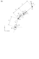
- FIG. 1 is a perspective view showing the configuration of a coupled vehicle according to an embodiment.
- FIG. 2 is a block diagram showing the configuration of a control system for the coupled vehicle shown in FIG. 1.
- FIG. 3 is a flowchart showing the procedure of processing executed by the control device of FIG.
- FIG. 4 is a diagram showing a model of the coupled vehicle of FIG. 1.
- FIG. 5 is a flowchart showing the procedure of processing executed by the control device in FIG.
- FIG. 6 is a flowchart showing the procedure of processing executed by the control device of FIG.
- FIG. 7 is a flowchart showing the procedure of processing executed by the control device of FIG. 8A to 8C are diagrams showing the relationship between the target virtual steering speed and the turning angular speed according to the same embodiment.
- the coupled vehicle 10 includes a tractor 20 and a trailer 30.
- the tractor 20 includes front wheels 22 and rear wheels 24.
- the front wheels 22 include two wheels, a right front wheel and a left front wheel
- the rear wheels 24 include two wheels, a right rear wheel and a left rear wheel.
- a box-shaped trailer is illustrated as the trailer 30.
- Trailer 30 has wheels 32 .
- the wheels 32 include two wheels, a right wheel and a left wheel.
- the trailer 30 is connected to the rear of the tractor 20 via a ball joint 40.
- the ball joint 40 is a member that rotatably connects the trailer 30 to the tractor 20 about a shaft 42 .
- the shaft 42 extends along the height direction of the tractor 20.
- the steering system 60 includes a steering actuator that steers steered wheels.
- the steered wheel is, for example, the front wheel 22 shown in FIG.
- the steering system 60 may include a steering control device that operates a steering actuator.
- the control device 50 operates the steering system 60 means that the control device 50 outputs a command signal to the steering control device.
- the drive system 62 includes at least one of an internal combustion engine and a rotating electric machine as a thrust generating device of the vehicle.
- the drive system 62 may include a drive control device that controls an internal combustion engine and a rotating electric machine.
- the control device 50 operates the drive system 62 means that the control device 50 outputs a command signal to the drive control device.
- the braking system 64 includes at least one of two devices: a device that decelerates the rotation of the wheels by frictional force, and a device that decelerates the rotation of the wheels by converting the power of the wheels into electrical energy.
- the device that decelerates the rotation of the wheels by converting it into electrical energy may be shared with the rotating electric machine of the drive system.
- the brake system 64 may include a brake control device that controls a device that decelerates the rotation of the wheels. In that case, "the control device 50 operates the brake system 62" means that the control device 50 outputs a command signal to the brake control device.
- the control device 50 refers to the steered angle ⁇ 1 of the steered wheels detected by the steered angle sensor 70 in order to control the control amount.
- the steering angle ⁇ 1 is a value in which one of the right turning and left turning has a positive sign and the other sign has a negative sign.
- the steering angle ⁇ 1 is the turning angle of the tire.
- the steering angle sensor 70 may be a sensor that detects the pinion angle.
- the control device 50 executes a process of converting the pinion angle into a turning angle of the tire. In the following, for convenience of explanation, even if the tire turning angle is obtained by the above converting process, the obtained tire turning angle will be regarded as the detected value of the steering angle sensor 70.
- the control device 50 also refers to the hitch angle ⁇ detected by the hitch angle sensor 72.
- the hitch angle ⁇ can take either a positive or negative sign depending on the angle formed between the direction in which the tractor 20 advances from the rear to the front and the direction in which the trailer 30 advances from the rear to the front.
- the sign of the hitch angle ⁇ may be positive when the direction in which the trailer 30 travels from the rear to the front deviates counterclockwise by less than 180 degrees with respect to the direction in which the tractor 20 travels from the rear to the front.
- the control device 50 refers to the wheel speeds ⁇ w1 to ⁇ w4 detected by the wheel speed sensor 74.
- the control device 50 includes a PU 52 and a storage device 54.
- the PU 52 is a software processing device including at least one of a CPU, a GPU, a TPU, and the like.
- the storage device 54 stores a reverse assist program 54a.
- the reverse assist program 54a is a program that specifies a command for causing the PU 52 to execute reverse assist processing.
- the reverse assist process is a process that automatically performs a process of turning the steerable wheels when the coupled vehicle 10 is traveling backwards.
- the reverse assist program 54a is a program for reducing the burden of reverse driving on the driver.
- the PU 52 first determines whether the vehicle is in the reverse assist mode (S10). When determining that the vehicle is in the reverse assist mode (S10: YES), the PU 52 acquires the target virtual steering angle ⁇ 2* input to the user interface 80 (S12).
- Target virtual steering angle ⁇ 2* is a target value of virtual steering angle ⁇ 2.
- the virtual steering angle ⁇ 2 is defined by the angle formed by the traveling direction of the ball joint 40 with respect to the longitudinal direction of the trailer 30.
- the target virtual steering angle ⁇ 2* is a variable indicating the driver's instruction for steering the trailer 30.
- the PU 52 acquires the hitch angle ⁇ detected by the hitch angle sensor 72 (S14). Further, the PU 52 acquires the steering angle ⁇ 1 detected by the steering angle sensor 70 (S16).
- FIG. 4 shows a model of the articulated vehicle 10 used in this embodiment.
- the pair of front wheels 22 of the tractor 20 are regarded as one front wheel C0
- the pair of rear wheels 24 of the tractor 20 are regarded as one rear wheel B1. That is, a two-wheel model is adopted for the tractor 20.
- the pair of wheels 32 of the trailer 30 is regarded as one wheel B2.
- the angle between the line defined by the front wheel C0 and the hitch point C1 and the line defined by the hitch point C1 and the wheel B2 is the hitch angle ⁇ .
- the hitch point C1 corresponds to the shaft 42 portion in FIG.
- front wheel speed VC0 which is the speed of front wheel C0
- the steering angle ⁇ 1 is quantified as the angle between the direction in which the front wheel C0 moves and a line defined by the front wheel C0 and the hitch point C1.
- the direction of vehicle speed V is parallel to the line defined by front wheel C0 and hitch point C1.
- the angle between the direction of the vehicle speed V and the x direction in FIG. 4 is an angle ⁇ 1.
- the angle between the line connecting the wheel B2 and the hitch point C1 and the x direction is an angle ⁇ 2.
- the distance l1 is the length between the front wheel C0 and the rear wheel B1.
- the distance h1 is the length between the rear wheel B1 and the hitch point C1.
- Distance l2 is the length between hitch point C1 and wheel B2.
- the direction of the speed VC1 at the hitch point C1 with respect to the direction from the wheel B2 to the hitch point C1 becomes the virtual steering angle ⁇ 2.
- the virtual steering angle ⁇ 2 becomes "-( ⁇ - ⁇ 1)".
- map data is set data of discrete values of input variables and values of output variables corresponding to each of the values of the input variables.
- the map calculation may be a process in which when the value of the input variable matches any of the values of the input variables of the map data, the value of the output variable of the corresponding map data is used as the calculation result.
- map calculation is a process in which when the value of an input variable does not match any of the values of input variables in map data, the calculation result is a value obtained by interpolating the values of multiple output variables included in map data. do it.
- the map operation will match the closest value among the values of the multiple input variables contained in the map data. It is also possible to use the value of the output variable of the map data as the calculation result.
- the PU 52 calculates a target turning angle ⁇ 1* as a manipulated variable by feedback control using the virtual steering angle ⁇ 2 as the controlled variable and the target virtual steering angle ⁇ 2* as the target value of the controlled variable (S20).
- the manipulated variable may be, for example, an output value of a proportional element whose input is the difference between the controlled variable and its target value. Further, for example, the manipulated variable may be the sum of the output value of an integral element and the output value of a proportional element that input the same difference. Further, for example, the manipulated variable may be the sum of an output value of a proportional element, an output value of an integral element, and an output value of a differential element, which input the same difference.
- the PU 52 calculates a manipulated variable for feedback control using the steered angle ⁇ 1 as the controlled variable and the target steered angle ⁇ 1* as the target controlled variable (S22). The PU 52 then operates the steering system 60 according to the amount of operation (S24).
- FIG. 5 shows a procedure for controlling the vehicle speed in the backward assist process.
- the process shown in FIG. 5 is realized by the PU 52 repeatedly executing the reverse assist program 54a at, for example, a predetermined cycle.
- the PU 52 first determines whether the vehicle is in the reverse assist control mode (S30). When determining that the vehicle is in the reverse assist control mode (S30: YES), the PU 52 acquires the user-set vehicle speed Vu (S32). The user-set vehicle speed Vu is the absolute value of the vehicle speed V of the connected vehicle 10 instructed by the driver through an input operation on the user interface 80 . Next, the PU 52 calculates the upper limit value Vth of the absolute value of the vehicle speed according to the current state of the connected vehicle 10 (S34).
- the PU 52 multiplies the minimum value of the user-set vehicle speed Vu, the upper limit value Vth, and the default value Vd by "-1" and assigns it to the target vehicle speed V* (S36).
- the reason for multiplying by "-1" is that the sign of the vehicle speed V when reversing is negative.
- the default value Vd is the upper limit of the absolute value of the vehicle speed that is predetermined from the stability margin. The stability margin in the reverse assist control mode becomes smaller as the absolute value of the vehicle speed V becomes larger. Therefore, the default value Vd is set so that the stability margin is equal to or higher than a certain value. Furthermore, the response characteristics of the steering system 60 are taken into account in the default value Vd.
- the PU 52 obtains the vehicle speed V (S38).
- the vehicle speed V is calculated by the PU 52 using at least one of the wheel speeds ⁇ w1 to ⁇ w4 detected by the wheel speed sensor 74 as input.
- the vehicle speed V may be, for example, the average value of the wheel speeds ⁇ w3 and ⁇ w4.
- the PU 52 calculates the manipulated variable for feedback control using the vehicle speed V as the controlled variable and the target vehicle speed V* as the target value of the controlled variable (S40).
- the operation amount is the driving force of the connected vehicle 10. However, the sign of the driving force can be both positive and negative. If the sign of the driving force is positive when the coupled vehicle 10 is moving backward, the driving force indicates the braking force of the coupled vehicle 10.
- the PU 52 operates the drive system 62 and the brake system 64 according to the amount of operation (S42).
- the PU52 acquires the target virtual steering angle ⁇ 2* (S50).
- the PU 52 receives the target virtual steering angle ⁇ 2* as an input and calculates the angle-dependent limit value Vth1 (S52).
- the angle-dependent limit value Vth1 is the upper limit of the absolute value of the vehicle speed V required to maintain controllability of control in which the virtual steering angle ⁇ 2 is the controlled variable and the target virtual steering angle ⁇ 2* is the target value of the controlled variable.
- the PU 52 sets the angle-dependent limit value Vth1 when the absolute value of the target virtual steering angle ⁇ 2* is large to be equal to or less than the angle-dependent limit value Vth1 when the absolute value of the target virtual steering angle ⁇ 2* is small.
- This process may be a process in which map data is stored in the storage device 54 in advance and the angle dependent limit value Vth1 is map-calculated by the PU 52.
- the map data is data that uses the absolute value of the target virtual steering angle ⁇ 2* as an input variable and uses the angle dependent limit value Vth1 as an output variable. Note that the value of the output variable included in the map data may decrease monotonically and strongly depending on the value of the input variable included in the map data.
- the PU 52 acquires the rate of change of the target virtual steering angle ⁇ 2* (S54).
- the rate of change of the target virtual steering angle ⁇ 2* is calculated by the PU 52 by inputting two or more sampled values of the target virtual steering angle ⁇ 2* acquired at mutually different timings.
- the PU 52 inputs the absolute value of the rate of change of the target virtual steering angle ⁇ 2* and calculates the speed-dependent limit value Vth2 (S56).
- the speed-dependent limit value Vth2 is an upper limit value of the vehicle speed V for suppressing a delay in following the actual virtual steering angle ⁇ 2 with respect to a change in the target virtual steering angle ⁇ 2*.
- the PU 52 sets the value of the speed dependent limit value Vth2 to one of two values depending on whether the absolute value of the rate of change of the target virtual steering angle ⁇ 2* is less than the threshold value Dth or greater than or equal to the threshold value Dth.
- the speed dependent limit value Vth2 when it is less than the threshold value Dth is larger than the speed dependent limit value Vth2 when it is equal to or more than the threshold value Dth.
- the virtual steering angle ⁇ 2 is smaller in the range in which the rate of change of the steering angle ⁇ 1 can be realized by the steering system 60.
- the range of possible values for the rate of change of is increasing.
- the jackknife hitch angle ⁇ th actually takes two values. These two jackknife hitch angles ⁇ th are stored in the storage device 54 in advance. In the process of S60, the PU 52 determines which of the two values the absolute value of the difference from the hitch angle ⁇ is smaller, depending on the sign of the steering angle ⁇ 1 and the sign of the rate of change of the steering angle ⁇ 1. Select a value.
- the PU 52 obtains the absolute value ⁇ of the difference between the target virtual steering angle ⁇ 2* and the virtual steering angle ⁇ 2 (S70).
- the absolute value ⁇ of the difference is calculated by the PU 52 using the target virtual steering angle ⁇ 2* and the virtual steering angle ⁇ 2 as input.
- the next PU 52 determines whether the restriction flag F is "1" (S72).
- the restriction flag F becomes "1” when the vehicle speed V is restricted to the small side due to the large absolute value ⁇ of the difference. Further, the restriction flag F becomes "0" when the same restriction is not applied.
- the PU 52 determines whether the absolute value ⁇ of the difference is smaller than the threshold value ⁇ th (S78). If the PU 52 determines that it is smaller than the threshold value ⁇ th (S78: YES), it increases the counter C by "1" (S80). The counter C measures the duration of time after the absolute value ⁇ of the difference switches from a state where it is greater than or equal to the threshold value ⁇ th to a state where it is less than the threshold value ⁇ th. On the other hand, when the PU 52 determines that it is equal to or greater than the threshold value ⁇ th (S78: NO), the PU 52 initializes the counter C (S82).
- the PU 52 substitutes the minimum value of the angle-dependent limit value Vth1, the speed-dependent limit value Vth2, the hitch angle-dependent limit value Vth3, and the deviation-dependent limit value Vth4 into the upper limit value Vth (S90).
- the PU 52 sets the minimum value of the absolute values of the user-set vehicle speed Vu, the upper limit value Vth, and the default value Vd as the absolute value of the target vehicle speed V*. This allows consideration of factors that cannot be expressed by the upper limit value Vth.
- the PU 52 executed the control of the virtual steering angle ⁇ 2 during the backward control of the coupled vehicle 10. Since the backward control of the coupled vehicle 10 is more difficult than the forward control, the PU 52 controls the virtual steering angle ⁇ 2 during the backward control, thereby making it possible to improve the controllability of the difficult backward control.
Abstract
This coupled vehicle is provided with a tractor and a trailer which is towed by the tractor. The coupled vehicle is provided with an interface (80) for a driver to indicate a target virtual steering angle which is a target value of a virtual steering angle. The virtual steering angle is a variable that indicates the advancing direction of a coupling portion of the trailer and the tractor. A control device (50) is configured to execute: a process to acquire the target virtual steering angle; a virtual steering angle control process for operating a steering system (60) of the coupled vehicle so as to control the virtual steering angle to the target virtual steering angle; and a process for limiting the absolute value of the vehicle speed of the coupled vehicle to a smaller value, using the target virtual steering angle as an input during the execution of the virtual steering angle control process.
Description
本開示は、連結車両の制御装置、連結車両の制御方法、および連結車両の制御プログラムに関する。
The present disclosure relates to a coupled vehicle control device, a coupled vehicle control method, and a coupled vehicle control program.
たとえば下記特許文献1には、連結車両の後退制御をアシストする制御装置が記載されている。この制御装置は、曲率半径が小さい経路を連結車両が走行している場合には、連結車両を経路に沿って走行させる制御を維持するために車速の絶対値を制限する。
For example, Patent Document 1 listed below describes a control device that assists in backward control of a coupled vehicle. This control device limits the absolute value of the vehicle speed in order to maintain control of driving the coupled vehicle along the route when the coupled vehicle is traveling on a route with a small radius of curvature.
上記制御装置では、連結車両の走行経路に応じて車速の絶対値を制限することによって、トレーラの進行方向を所望の方向に維持しうる。ただし、連結車両の経路自体は、トレーラの進行方向を直接的に定める変数ではない。そのため、トレーラの進行方向を制御するうえでの制御性が必ずしも高くない。
The above control device can maintain the traveling direction of the trailer in a desired direction by limiting the absolute value of the vehicle speed according to the travel route of the connected vehicle. However, the route of the coupled vehicle itself is not a variable that directly determines the traveling direction of the trailer. Therefore, the controllability in controlling the traveling direction of the trailer is not necessarily high.
本開示の一態様では、トラクタと、前記トラクタによって牽引されるトレーラと、を備える連結車両の制御装置が提供される。前記連結車両は、運転者が目標仮想操舵角を指示するためのインターフェースを備える。前記目標仮想操舵角は、仮想操舵角の目標値である。前記仮想操舵角は、前記トレーラと前記トラクタとの連結箇所の進行方向を示す変数である。前記制御装置は、目標仮想操舵角取得処理、仮想操舵角制御処理、および車速制限処理を実行するように構成されている。前記目標仮想操舵角取得処理は、前記目標仮想操舵角を取得する処理である。前記仮想操舵角制御処理は、前記仮想操舵角を前記目標仮想操舵角に制御すべく前記連結車両の操舵系を操作する処理を含む。前記車速制限処理は、前記仮想操舵角制御処理の実行中に、前記連結車両の車速の絶対値を小さい側に制限する処理であって且つ、前記目標仮想操舵角を入力として前記車速の絶対値を小さい側に制限する仮想操舵角依存処理を含む。
One aspect of the present disclosure provides a control device for a coupled vehicle that includes a tractor and a trailer towed by the tractor. The articulated vehicle includes an interface through which a driver indicates a target virtual steering angle. The target virtual steering angle is a target value of the virtual steering angle. The virtual steering angle is a variable that indicates the traveling direction of a connection point between the trailer and the tractor. The control device is configured to execute target virtual steering angle acquisition processing, virtual steering angle control processing, and vehicle speed restriction processing. The target virtual steering angle acquisition process is a process of acquiring the target virtual steering angle. The virtual steering angle control process includes a process of operating the steering system of the coupled vehicle to control the virtual steering angle to the target virtual steering angle. The vehicle speed limiting process is a process that limits the absolute value of the vehicle speed of the connected vehicle to a smaller side during execution of the virtual steering angle control process, and uses the target virtual steering angle as input to limit the absolute value of the vehicle speed. includes virtual steering angle dependent processing that limits the steering angle to the small side.
本開示の別の態様では、トラクタと、前記トラクタによって牽引されるトレーラと、を備える連結車両の制御方法が提供される。前記連結車両は、運転者が目標仮想操舵角を指示するためのインターフェースを備える。前記目標仮想操舵角は、仮想操舵角の目標値である。前記仮想操舵角は、前記トレーラと前記トラクタとの連結箇所の進行方向を示す変数である。前記制御方法は、目標仮想操舵角取得処理、仮想操舵角制御処理、および車速制限処理を実行する工程を有する。前記目標仮想操舵角取得処理は、前記目標仮想操舵角を取得する処理である。前記仮想操舵角制御処理は、前記仮想操舵角を前記目標仮想操舵角に制御すべく前記連結車両の操舵系を操作する処理を含む。前記車速制限処理は、前記仮想操舵角制御処理の実行中に、前記連結車両の車速の絶対値を小さい側に制限する処理であって且つ、前記目標仮想操舵角を入力として前記車速の絶対値を小さい側に制限する仮想操舵角依存処理を含む。
Another aspect of the present disclosure provides a method for controlling a coupled vehicle that includes a tractor and a trailer towed by the tractor. The articulated vehicle includes an interface through which a driver indicates a target virtual steering angle. The target virtual steering angle is a target value of the virtual steering angle. The virtual steering angle is a variable that indicates the traveling direction of a connection point between the trailer and the tractor. The control method includes the steps of executing target virtual steering angle acquisition processing, virtual steering angle control processing, and vehicle speed restriction processing. The target virtual steering angle acquisition process is a process of acquiring the target virtual steering angle. The virtual steering angle control process includes a process of operating the steering system of the coupled vehicle to control the virtual steering angle to the target virtual steering angle. The vehicle speed limiting process is a process that limits the absolute value of the vehicle speed of the connected vehicle to a smaller side during execution of the virtual steering angle control process, and uses the target virtual steering angle as input to limit the absolute value of the vehicle speed. includes virtual steering angle dependent processing that limits the steering angle to the small side.
本開示の一態様では、トラクタと、前記トラクタによって牽引されるトレーラと、を備える連結車両の制御プログラムが提供される。前記連結車両は、運転者が目標仮想操舵角を指示するためのインターフェースを備える。前記目標仮想操舵角は、仮想操舵角の目標値である。前記仮想操舵角は、前記トレーラと前記トラクタとの連結箇所の進行方向を示す変数である。前記制御プログラムは、目標仮想操舵角取得処理、仮想操舵角制御処理、および車速制限処理をコンピュータに実行させる指令を含む。前記目標仮想操舵角取得処理は、前記目標仮想操舵角を取得する処理である。前記仮想操舵角制御処理は、前記仮想操舵角を前記目標仮想操舵角に制御すべく前記連結車両の操舵系を操作する処理を含む。前記車速制限処理は、前記仮想操舵角制御処理の実行中に、前記連結車両の車速の絶対値を小さい側に制限する処理であって且つ、前記目標仮想操舵角を入力として前記車速の絶対値を小さい側に制限する仮想操舵角依存処理を含む。
In one aspect of the present disclosure, a control program for a coupled vehicle including a tractor and a trailer towed by the tractor is provided. The articulated vehicle includes an interface through which a driver indicates a target virtual steering angle. The target virtual steering angle is a target value of the virtual steering angle. The virtual steering angle is a variable that indicates the traveling direction of a connection point between the trailer and the tractor. The control program includes instructions for causing the computer to execute target virtual steering angle acquisition processing, virtual steering angle control processing, and vehicle speed restriction processing. The target virtual steering angle acquisition process is a process of acquiring the target virtual steering angle. The virtual steering angle control process includes a process of operating the steering system of the coupled vehicle to control the virtual steering angle to the target virtual steering angle. The vehicle speed limiting process is a process that limits the absolute value of the vehicle speed of the connected vehicle to a smaller side during execution of the virtual steering angle control process, and uses the target virtual steering angle as input to limit the absolute value of the vehicle speed. includes virtual steering angle dependent processing that limits the steering angle to the small side.
以下、実施形態について図面を参照しつつ説明する。
「連結車両の構成」
図1に示すように、連結車両10は、トラクタ20およびトレーラ30を有している。トラクタ20は、前輪22および後輪24を備える。前輪22は右前輪および左前輪の2輪を含み、後輪24は右後輪および左後輪の2輪を含む。また、図1には、トレーラ30として、箱型のトレーラを例示する。トレーラ30は、車輪32を有している。車輪32は、右車輪および左車輪の2輪を含む。 Hereinafter, embodiments will be described with reference to the drawings.
"Composition of connected vehicles"
As shown in FIG. 1, the coupledvehicle 10 includes a tractor 20 and a trailer 30. The tractor 20 includes front wheels 22 and rear wheels 24. The front wheels 22 include two wheels, a right front wheel and a left front wheel, and the rear wheels 24 include two wheels, a right rear wheel and a left rear wheel. Further, in FIG. 1, a box-shaped trailer is illustrated as the trailer 30. Trailer 30 has wheels 32 . The wheels 32 include two wheels, a right wheel and a left wheel.
「連結車両の構成」
図1に示すように、連結車両10は、トラクタ20およびトレーラ30を有している。トラクタ20は、前輪22および後輪24を備える。前輪22は右前輪および左前輪の2輪を含み、後輪24は右後輪および左後輪の2輪を含む。また、図1には、トレーラ30として、箱型のトレーラを例示する。トレーラ30は、車輪32を有している。車輪32は、右車輪および左車輪の2輪を含む。 Hereinafter, embodiments will be described with reference to the drawings.
"Composition of connected vehicles"
As shown in FIG. 1, the coupled
トレーラ30は、ボールジョイント40を介してトラクタ20の後部に連結されている。ボールジョイント40は、トレーラ30を、トラクタ20に対して軸42を中心として回転可能に連結する部材である。軸42は、トラクタ20の高さ方向に沿って延びる。
The trailer 30 is connected to the rear of the tractor 20 via a ball joint 40. The ball joint 40 is a member that rotatably connects the trailer 30 to the tractor 20 about a shaft 42 . The shaft 42 extends along the height direction of the tractor 20.
図2に、トラクタ20が備える部材の一部を示す。図2に示すように、トラクタ20は、制御装置50を備えている。制御装置50は、制御対象である連結車両10の制御量を制御すべく、操舵系60、駆動系62、および制動系64を操作する。制御量は、車速、走行方向、およびヒッチ角等である。ヒッチ角は、トラクタ20の前後方向とトレーラ30の前後方向とのなす角度である。
FIG. 2 shows some of the members included in the tractor 20. As shown in FIG. 2, the tractor 20 includes a control device 50. The control device 50 operates the steering system 60, the drive system 62, and the braking system 64 in order to control the control amount of the connected vehicle 10 that is the object of control. The controlled variables include vehicle speed, traveling direction, hitch angle, and the like. The hitch angle is an angle between the longitudinal direction of the tractor 20 and the longitudinal direction of the trailer 30.
操舵系60は、転舵輪を転舵させる転舵アクチュエータを含む。転舵輪は、たとえば、図1に示す前輪22である。なお、操舵系60に転舵アクチュエータを操作する転舵制御装置を含めてもよい。その場合、「制御装置50が操舵系60を操作する」とは、制御装置50が転舵制御装置に指令信号を出力することを意味する。
The steering system 60 includes a steering actuator that steers steered wheels. The steered wheel is, for example, the front wheel 22 shown in FIG. Note that the steering system 60 may include a steering control device that operates a steering actuator. In that case, "the control device 50 operates the steering system 60" means that the control device 50 outputs a command signal to the steering control device.
駆動系62は、車両の推力生成装置としての、内燃機関および回転電機の2つのうちの少なくとも1つを含む。なお、駆動系62に、内燃機関および回転電機を制御対象とする駆動制御装置を含めてもよい。その場合、「制御装置50が駆動系62を操作する」とは、制御装置50が駆動制御装置に指令信号を出力することを意味する。
The drive system 62 includes at least one of an internal combustion engine and a rotating electric machine as a thrust generating device of the vehicle. Note that the drive system 62 may include a drive control device that controls an internal combustion engine and a rotating electric machine. In that case, "the control device 50 operates the drive system 62" means that the control device 50 outputs a command signal to the drive control device.
制動系64は、摩擦力によって車輪の回転を減速させる装置と、車輪の動力を電気エネルギに変換することによって車輪の回転を減速させる装置との2つのうちの少なくとも1つを含む。なお、電気エネルギに変換することによって車輪の回転を減速させる装置は、駆動系の回転電機と共有されていてもよい。なお、制動系64に、車輪の回転を減速させる装置を制御対象とする制動制御装置を含めてもよい。その場合、「制御装置50が制動系62を操作する」とは、制御装置50が制動制御装置に指令信号を出力することを意味する。
The braking system 64 includes at least one of two devices: a device that decelerates the rotation of the wheels by frictional force, and a device that decelerates the rotation of the wheels by converting the power of the wheels into electrical energy. Note that the device that decelerates the rotation of the wheels by converting it into electrical energy may be shared with the rotating electric machine of the drive system. Note that the brake system 64 may include a brake control device that controls a device that decelerates the rotation of the wheels. In that case, "the control device 50 operates the brake system 62" means that the control device 50 outputs a command signal to the brake control device.
制御装置50は、制御量を制御すべく、舵角センサ70によって検出される転舵輪の転舵角α1を参照する。転舵角α1は、右旋回および左旋回のうちのいずれか一方の符号が正、他方の符号が負となる値である。転舵角α1は、タイヤの切れ角である。なお、たとえば操舵系60がラックアンドピニオン機構を備える場合、舵角センサ70をピニオン角を検出するセンサとしてもよい。ただし、その場合、制御装置50がピニオン角をタイヤの切れ角に変換する処理を実行する。以下では、説明の便宜上、タイヤの切れ角が上記変換する処理によって得られたものであっても、得られたタイヤの切れ角を舵角センサ70の検出値と見なす。
The control device 50 refers to the steered angle α1 of the steered wheels detected by the steered angle sensor 70 in order to control the control amount. The steering angle α1 is a value in which one of the right turning and left turning has a positive sign and the other sign has a negative sign. The steering angle α1 is the turning angle of the tire. Note that, for example, when the steering system 60 includes a rack and pinion mechanism, the steering angle sensor 70 may be a sensor that detects the pinion angle. However, in that case, the control device 50 executes a process of converting the pinion angle into a turning angle of the tire. In the following, for convenience of explanation, even if the tire turning angle is obtained by the above converting process, the obtained tire turning angle will be regarded as the detected value of the steering angle sensor 70.
また制御装置50は、ヒッチ角センサ72によって検出されるヒッチ角βを参照する。ヒッチ角βは、トラクタ20の後方から前方に進む方向とトレーラ30の後方から前方に進む方向とのなす角度に応じて正、負の双方の符号を取り得る。たとえば、トラクタ20の後方から前方に進む方向に対してトレーラ30の後方から前方に進む方向が反時計回りに180°未満ずれる場合のヒッチ角βの符号を、正としてもよい。また、制御装置50は、車輪速センサ74によって検出される車輪速度ωw1~ωw4を参照する。車輪速度ωw1,ωw2は、それぞれ、右側の前輪22の回転速度、および左側の前輪22の回転速度である。車輪速度ωw3,ωw4は、それぞれ、右側の後輪24の回転速度、および左側の後輪24の回転速度である。
The control device 50 also refers to the hitch angle β detected by the hitch angle sensor 72. The hitch angle β can take either a positive or negative sign depending on the angle formed between the direction in which the tractor 20 advances from the rear to the front and the direction in which the trailer 30 advances from the rear to the front. For example, the sign of the hitch angle β may be positive when the direction in which the trailer 30 travels from the rear to the front deviates counterclockwise by less than 180 degrees with respect to the direction in which the tractor 20 travels from the rear to the front. Further, the control device 50 refers to the wheel speeds ωw1 to ωw4 detected by the wheel speed sensor 74. The wheel speeds ωw1 and ωw2 are the rotational speed of the right front wheel 22 and the rotational speed of the left front wheel 22, respectively. The wheel speeds ωw3 and ωw4 are the rotational speed of the right rear wheel 24 and the rotational speed of the left rear wheel 24, respectively.
制御装置50は、制御量の制御を、ユーザインターフェース80の操作状態に応じて設定する。ユーザインターフェース80は、自動運転および手動運転の2つのうちのいずれか1つを選択する等、ユーザの意思を制御装置50に伝達するためのものである。
The control device 50 sets the control amount according to the operating state of the user interface 80. The user interface 80 is for transmitting the user's intention to the control device 50, such as selecting one of automatic operation and manual operation.
制御装置50は、PU52および記憶装置54を備えている。PU52は、CPU、GPU、およびTPU等の少なくとも1つを備えるソフトウェア処理装置である。記憶装置54には、後退アシストプログラム54aが記憶されている。後退アシストプログラム54aは、PU52に、後退アシスト処理を実行させる指令を規定するプログラムである。後退アシスト処理は、連結車両10の後退走行において転舵輪の転舵処理を自動で行う処理である。後退アシストプログラム54aは、運転者による後退運転の負荷を軽減するためのプログラムである。
The control device 50 includes a PU 52 and a storage device 54. The PU 52 is a software processing device including at least one of a CPU, a GPU, a TPU, and the like. The storage device 54 stores a reverse assist program 54a. The reverse assist program 54a is a program that specifies a command for causing the PU 52 to execute reverse assist processing. The reverse assist process is a process that automatically performs a process of turning the steerable wheels when the coupled vehicle 10 is traveling backwards. The reverse assist program 54a is a program for reducing the burden of reverse driving on the driver.
すなわち、連結車両10の後退走行においては、トラクタ20の転舵角α1が同一であっても、トレーラ30の挙動は、ヒッチ角βに応じて変化する。そのため、後退制御には、高い運転技能が要求される。後退アシストプログラム54aによる後退アシスト処理は、トラクタ20の転舵角α1を制御することによって運転者をアシストする処理である。ただし、後退アシスト処理は、トレーラ30の操舵に対する指示を運転者に委ねる。これは、トレーラ30の操舵をも制御装置50が設定する場合には、制御装置50に対する要求が高くなるためである。運転者に一部の指示をゆだねることにより、比較的簡素な処理によって後退制御を実行することが可能となる。
That is, when the coupled vehicle 10 is traveling backwards, even if the steering angle α1 of the tractor 20 is the same, the behavior of the trailer 30 changes depending on the hitch angle β. Therefore, high driving skills are required for reverse control. The reverse assist process by the reverse assist program 54a is a process that assists the driver by controlling the turning angle α1 of the tractor 20. However, the backward assist process leaves instructions for steering the trailer 30 to the driver. This is because when the control device 50 also sets the steering of the trailer 30, the demands on the control device 50 become higher. By entrusting some instructions to the driver, it becomes possible to execute reverse control through relatively simple processing.
「後退アシスト処理における操舵」
図3に後退アシスト処理における操舵に関する処理の手順を示す。図3に示す処理は、PU52が後退アシストプログラム54aをたとえば所定周期で繰り返し実行することにより実現される。なお、以下では、先頭に「S」が付与された数字によって、各処理のステップ番号を表現する。 "Steering in reverse assist processing"
FIG. 3 shows the procedure of processing related to steering in the reverse assist processing. The process shown in FIG. 3 is realized by thePU 52 repeatedly executing the reverse assist program 54a at, for example, a predetermined period. Note that in the following, the step number of each process is expressed by a number prefixed with "S".
図3に後退アシスト処理における操舵に関する処理の手順を示す。図3に示す処理は、PU52が後退アシストプログラム54aをたとえば所定周期で繰り返し実行することにより実現される。なお、以下では、先頭に「S」が付与された数字によって、各処理のステップ番号を表現する。 "Steering in reverse assist processing"
FIG. 3 shows the procedure of processing related to steering in the reverse assist processing. The process shown in FIG. 3 is realized by the
図3に示す一連の処理において、PU52は、まず、後退アシストモードであるか否かを判定する(S10)。PU52は、後退アシストモードであると判定する場合(S10:YES)、ユーザインターフェース80に入力された目標仮想操舵角α2*を取得する(S12)。目標仮想操舵角α2*は、仮想操舵角α2の目標値である。本実施形態では、一例として、トレーラ30の前後方向に対するボールジョイント40の進行方向のなす角度によって、仮想操舵角α2を定義する。目標仮想操舵角α2*は、トレーラ30の操舵に対する運転者の指示を示す変数である。
In the series of processes shown in FIG. 3, the PU 52 first determines whether the vehicle is in the reverse assist mode (S10). When determining that the vehicle is in the reverse assist mode (S10: YES), the PU 52 acquires the target virtual steering angle α2* input to the user interface 80 (S12). Target virtual steering angle α2* is a target value of virtual steering angle α2. In this embodiment, as an example, the virtual steering angle α2 is defined by the angle formed by the traveling direction of the ball joint 40 with respect to the longitudinal direction of the trailer 30. The target virtual steering angle α2* is a variable indicating the driver's instruction for steering the trailer 30.
次にPU52は、ヒッチ角センサ72によって検出されたヒッチ角βを取得する(S14)。また、PU52は、舵角センサ70によって検出された転舵角α1を取得する(S16)。
Next, the PU 52 acquires the hitch angle β detected by the hitch angle sensor 72 (S14). Further, the PU 52 acquires the steering angle α1 detected by the steering angle sensor 70 (S16).
そして、PU72は、転舵角α1およびヒッチ角βを入力として、仮想操舵角α2を算出する(S18)。ここで、図4に基づき、仮想操舵角α2を転舵角α1およびヒッチ角βから算出する理由を説明する。
Then, the PU 72 calculates a virtual steering angle α2 by inputting the steering angle α1 and the hitch angle β (S18). Here, the reason why the virtual steering angle α2 is calculated from the steering angle α1 and the hitch angle β will be explained based on FIG.
図4は、本実施形態で用いる連結車両10のモデルを示す。図4に示すモデルは、トラクタ20の一対の前輪22を1つの前輪C0とみなして且つ、トラクタ20の一対の後輪24を1つの後輪B1とみなす。すなわち、トラクタ20について2輪モデルを採用している。また、トレーラ30の一対の車輪32を1つの車輪B2とみなす。前輪C0およびヒッチ点C1によって定まる線と、ヒッチ点C1および車輪B2によって定まる線とのなす角が、ヒッチ角βである。ヒッチ点C1は、図1の軸42部分に相当する。また、前輪C0の速度である前輪速度VC0は、転舵角α1の方向に進むベクトルである。転舵角α1は、前輪C0の進む方向と、前輪C0およびヒッチ点C1によって定まる線とのなす角度として定量化されている。車速Vの方向は、前輪C0およびヒッチ点C1によって定まる線に平行である。また、車速Vの方向と、図4のx方向とのなす角は、角度θ1である。また、車輪B2とヒッチ点C1とを結ぶ線とx方向とのなす角は、角度θ2である。また、距離l1は、前輪C0および後輪B1間の長さである。また、距離h1は、後輪B1およびヒッチ点C1間の長さである。距離l2は、ヒッチ点C1および車輪B2間の長さである。
FIG. 4 shows a model of the articulated vehicle 10 used in this embodiment. In the model shown in FIG. 4, the pair of front wheels 22 of the tractor 20 are regarded as one front wheel C0, and the pair of rear wheels 24 of the tractor 20 are regarded as one rear wheel B1. That is, a two-wheel model is adopted for the tractor 20. Further, the pair of wheels 32 of the trailer 30 is regarded as one wheel B2. The angle between the line defined by the front wheel C0 and the hitch point C1 and the line defined by the hitch point C1 and the wheel B2 is the hitch angle β. The hitch point C1 corresponds to the shaft 42 portion in FIG. Further, front wheel speed VC0, which is the speed of front wheel C0, is a vector that moves in the direction of steering angle α1. The steering angle α1 is quantified as the angle between the direction in which the front wheel C0 moves and a line defined by the front wheel C0 and the hitch point C1. The direction of vehicle speed V is parallel to the line defined by front wheel C0 and hitch point C1. Further, the angle between the direction of the vehicle speed V and the x direction in FIG. 4 is an angle θ1. Further, the angle between the line connecting the wheel B2 and the hitch point C1 and the x direction is an angle θ2. Moreover, the distance l1 is the length between the front wheel C0 and the rear wheel B1. Further, the distance h1 is the length between the rear wheel B1 and the hitch point C1. Distance l2 is the length between hitch point C1 and wheel B2.
上述した定義によれば、車輪B2からヒッチ点C1に進む方向に対するヒッチ点C1の速度VC1の方向が仮想操舵角α2となる。ヒッチ点C1から前輪C0に進む方向に対するヒッチ点C1の速度VC1の方向のなす角度γ1を用いると、仮想操舵角α2は、「-(β-γ1)」となる。
According to the above definition, the direction of the speed VC1 at the hitch point C1 with respect to the direction from the wheel B2 to the hitch point C1 becomes the virtual steering angle α2. Using the angle γ1 formed by the direction of the speed VC1 of the hitch point C1 with respect to the direction of travel from the hitch point C1 to the front wheel C0, the virtual steering angle α2 becomes "-(β-γ1)".
図4に示すモデルにおいて、前輪C0の座標(xc0,yc0)、後輪B1の座標(xb1,yb1)およびヒッチ点C1の座標(xc1,yc1)を用いると、以下の式(c1)~(c3)が成立する。
In the model shown in FIG. 4, using the coordinates of the front wheel C0 (xc0, yc0), the coordinates of the rear wheel B1 (xb1, yb1), and the coordinates of the hitch point C1 (xc1, yc1), the following equations (c1) to ( c3) holds true.
VC0・cosα1=VB1 …(c1)
xc0=xb1+l1・cosθ1 …(c2)
xc1=xb1-h1・cosθ1 …(c3)
上記の式(c2),(c3)の両辺を微分した式および式(c1)を用いると、以下の式(c4)が得られる。 VC0・cosα1=VB1…(c1)
xc0=xb1+l1・cosθ1...(c2)
xc1=xb1-h1・cosθ1...(c3)
Using the equation obtained by differentiating both sides of the above equations (c2) and (c3) and the equation (c1), the following equation (c4) is obtained.
h1・tanα1+l1・tanγ1=0 …(c4)
上記の式(c4)によれば、角度γ1が転舵角α1によって表現できる。したがって、仮想操舵角α2は、以下の式(c5)にて表現される。 h1・tanα1+l1・tanγ1=0…(c4)
According to the above equation (c4), the angle γ1 can be expressed by the steering angle α1. Therefore, the virtual steering angle α2 is expressed by the following equation (c5).
上記の式(c4)によれば、角度γ1が転舵角α1によって表現できる。したがって、仮想操舵角α2は、以下の式(c5)にて表現される。 h1・tanα1+l1・tanγ1=0…(c4)
According to the above equation (c4), the angle γ1 can be expressed by the steering angle α1. Therefore, the virtual steering angle α2 is expressed by the following equation (c5).
α2=-β-arctan{(h1/l1)・tan(α1)} …(c5)
すなわち、仮想操舵角α2は、ヒッチ角βおよび転舵角α1から求めることができる。
図3には、上記の式(c5)を記載しているが、実際には、記憶装置54にマップデータを記憶しておくことにより、PU52は、S18の処理において、仮想操舵角α2をマップ演算してもよい。マップデータは、ヒッチ角βおよび転舵角α1を入力変数として且つ、仮想操舵角α2を出力変数とする。 α2=-β-arctan {(h1/l1)・tan(α1)}...(c5)
That is, the virtual steering angle α2 can be determined from the hitch angle β and the steering angle α1.
Although the above equation (c5) is shown in FIG. 3, in reality, by storing map data in thestorage device 54, the PU 52 maps the virtual steering angle α2 in the process of S18. It may be calculated. The map data uses the hitch angle β and the steering angle α1 as input variables, and uses the virtual steering angle α2 as an output variable.
すなわち、仮想操舵角α2は、ヒッチ角βおよび転舵角α1から求めることができる。
図3には、上記の式(c5)を記載しているが、実際には、記憶装置54にマップデータを記憶しておくことにより、PU52は、S18の処理において、仮想操舵角α2をマップ演算してもよい。マップデータは、ヒッチ角βおよび転舵角α1を入力変数として且つ、仮想操舵角α2を出力変数とする。 α2=-β-arctan {(h1/l1)・tan(α1)}...(c5)
That is, the virtual steering angle α2 can be determined from the hitch angle β and the steering angle α1.
Although the above equation (c5) is shown in FIG. 3, in reality, by storing map data in the
ここで、マップデータとは、入力変数の離散的な値と、入力変数の値のそれぞれに対応する出力変数の値と、の組データである。また、マップ演算は、入力変数の値がマップデータの入力変数の値のいずれかに一致する場合、対応するマップデータの出力変数の値を演算結果とする処理とすればよい。また、マップ演算は、入力変数の値がマップデータの入力変数の値のいずれにも一致しない場合、マップデータに含まれる複数の出力変数の値の補間によって得られる値を演算結果とする処理とすればよい。また、これに代えて、マップ演算は、入力変数の値がマップデータの入力変数の値のいずれにも一致しない場合、マップデータに含まれる複数の入力変数の値のうちの最も近い値に対応するマップデータの出力変数の値を演算結果とする処理としてもよい。
Here, map data is set data of discrete values of input variables and values of output variables corresponding to each of the values of the input variables. Furthermore, the map calculation may be a process in which when the value of the input variable matches any of the values of the input variables of the map data, the value of the output variable of the corresponding map data is used as the calculation result. Additionally, map calculation is a process in which when the value of an input variable does not match any of the values of input variables in map data, the calculation result is a value obtained by interpolating the values of multiple output variables included in map data. do it. Alternatively, if the value of the input variable does not match any of the values of the input variables in the map data, the map operation will match the closest value among the values of the multiple input variables contained in the map data. It is also possible to use the value of the output variable of the map data as the calculation result.
次に、PU52は、仮想操舵角α2を制御量として且つ目標仮想操舵角α2*を制御量の目標値とするフィードバック制御による操作量としての目標転舵角α1*を算出する(S20)。操作量は、たとえば、制御量とその目標値との差を入力とする比例要素の出力値であってもよい。また、たとえば、操作量は、同差を入力とする積分要素の出力値および比例要素の出力値の和であってもよい。また、たとえば、操作量は、同差を入力とする比例要素の出力値、積分要素の出力値および微分要素の出力値の和であってもよい。
Next, the PU 52 calculates a target turning angle α1* as a manipulated variable by feedback control using the virtual steering angle α2 as the controlled variable and the target virtual steering angle α2* as the target value of the controlled variable (S20). The manipulated variable may be, for example, an output value of a proportional element whose input is the difference between the controlled variable and its target value. Further, for example, the manipulated variable may be the sum of the output value of an integral element and the output value of a proportional element that input the same difference. Further, for example, the manipulated variable may be the sum of an output value of a proportional element, an output value of an integral element, and an output value of a differential element, which input the same difference.
次に、PU52は、転舵角α1を制御量として且つ目標転舵角α1*を目標制御量とするフィードバック制御のための操作量を算出する(S22)。そしてPU52は、操作量に応じて操舵系60を操作する(S24)。
Next, the PU 52 calculates a manipulated variable for feedback control using the steered angle α1 as the controlled variable and the target steered angle α1* as the target controlled variable (S22). The PU 52 then operates the steering system 60 according to the amount of operation (S24).
なお、PU52は、S24の処理を完了する場合と、S10の処理において否定判定する場合と、には、図3に示す一連の処理を一旦終了する。
「後退アシスト処理における車速の制御」
図5に、後退アシスト処理における車速の制御に関する処理の手順を示す。図5に示す処理は、PU52が後退アシストプログラム54aをたとえば所定周期で繰り返し実行することにより実現される。 Note that thePU 52 temporarily ends the series of processes shown in FIG. 3 when completing the process of S24 and when making a negative determination in the process of S10.
"Vehicle speed control in reverse assist processing"
FIG. 5 shows a procedure for controlling the vehicle speed in the backward assist process. The process shown in FIG. 5 is realized by thePU 52 repeatedly executing the reverse assist program 54a at, for example, a predetermined cycle.
「後退アシスト処理における車速の制御」
図5に、後退アシスト処理における車速の制御に関する処理の手順を示す。図5に示す処理は、PU52が後退アシストプログラム54aをたとえば所定周期で繰り返し実行することにより実現される。 Note that the
"Vehicle speed control in reverse assist processing"
FIG. 5 shows a procedure for controlling the vehicle speed in the backward assist process. The process shown in FIG. 5 is realized by the
図5に示す一連の処理において、PU52は、まず後退アシスト制御モードであるか否かを判定する(S30)。PU52は、後退アシスト制御モードであると判定する場合(S30:YES)、ユーザ設定車速Vuを取得する(S32)。ユーザ設定車速Vuは、ユーザインターフェース80の入力操作によって運転者によって指示される連結車両10の車速Vの絶対値である。次に、PU52は、連結車両10の現在の状態に応じた車速の絶対値の上限値Vthを算出する(S34)。
In the series of processes shown in FIG. 5, the PU 52 first determines whether the vehicle is in the reverse assist control mode (S30). When determining that the vehicle is in the reverse assist control mode (S30: YES), the PU 52 acquires the user-set vehicle speed Vu (S32). The user-set vehicle speed Vu is the absolute value of the vehicle speed V of the connected vehicle 10 instructed by the driver through an input operation on the user interface 80 . Next, the PU 52 calculates the upper limit value Vth of the absolute value of the vehicle speed according to the current state of the connected vehicle 10 (S34).
そして、PU52は、ユーザ設定車速Vu、上限値Vthおよびデフォルト値Vdのうちの最小値に「-1」を乗算した値を目標車速V*に代入する(S36)。「-1」を乗算するのは、後退時の車速Vの符号を負としているためである。デフォルト値Vdは、安定余裕度から予め定められる車速の絶対値の上限値である。後退アシスト制御モードにおける安定余裕度は、車速Vの絶対値が大きくなるほど小さくなる。そのため、安定余裕度が一定値以上となるようにデフォルト値Vdが設定されている。また、デフォルト値Vdには、操舵系60の応答特性が加味されている。
Then, the PU 52 multiplies the minimum value of the user-set vehicle speed Vu, the upper limit value Vth, and the default value Vd by "-1" and assigns it to the target vehicle speed V* (S36). The reason for multiplying by "-1" is that the sign of the vehicle speed V when reversing is negative. The default value Vd is the upper limit of the absolute value of the vehicle speed that is predetermined from the stability margin. The stability margin in the reverse assist control mode becomes smaller as the absolute value of the vehicle speed V becomes larger. Therefore, the default value Vd is set so that the stability margin is equal to or higher than a certain value. Furthermore, the response characteristics of the steering system 60 are taken into account in the default value Vd.
次にPU52は、車速Vを取得する(S38)。車速Vは、PU52によって、車輪速センサ74によって検出される車輪速度ωw1~ωw4の少なくとも1つを入力として算出される。車速Vは、たとえば、車輪速度ωw3,ωw4の平均値であってもよい。次にPU52は、車速Vを制御量として且つ目標車速V*を制御量の目標値とするフィードバック制御のための操作量を算出する(S40)。操作量は、連結車両10の駆動力である。ただし、駆動力の符号は正および負の双方となりうる。連結車両10の後退時において駆動力の符号が正である場合、駆動力は、連結車両10の制動力を示す。PU52は、操作量に応じて駆動系62および制動系64を操作する(S42)。
Next, the PU 52 obtains the vehicle speed V (S38). The vehicle speed V is calculated by the PU 52 using at least one of the wheel speeds ωw1 to ωw4 detected by the wheel speed sensor 74 as input. The vehicle speed V may be, for example, the average value of the wheel speeds ωw3 and ωw4. Next, the PU 52 calculates the manipulated variable for feedback control using the vehicle speed V as the controlled variable and the target vehicle speed V* as the target value of the controlled variable (S40). The operation amount is the driving force of the connected vehicle 10. However, the sign of the driving force can be both positive and negative. If the sign of the driving force is positive when the coupled vehicle 10 is moving backward, the driving force indicates the braking force of the coupled vehicle 10. The PU 52 operates the drive system 62 and the brake system 64 according to the amount of operation (S42).
なお、PU52は、S42の処理を完了する場合と、S30の処理において否定判定する場合と、には、図5に示す一連の処理を一旦終了する。
図6および図7に、S34の処理の詳細を示す。 Note that thePU 52 temporarily ends the series of processes shown in FIG. 5 when completing the process of S42 and when making a negative determination in the process of S30.
6 and 7 show details of the process in S34.
図6および図7に、S34の処理の詳細を示す。 Note that the
6 and 7 show details of the process in S34.
図6に示すように、PU52は、目標仮想操舵角α2*を取得する(S50)。次にPU52は、目標仮想操舵角α2*を入力として、角度依存制限値Vth1を算出する(S52)。角度依存制限値Vth1は、仮想操舵角α2を制御量として且つ目標仮想操舵角α2*を制御量の目標値とする制御の制御性を維持するうえで要求される車速Vの絶対値の上限値を定める変数である。PU52は、目標仮想操舵角α2*の絶対値が大きい場合の角度依存制限値Vth1を、目標仮想操舵角α2*の絶対値が小さい場合の角度依存制限値Vth1以下とする。この処理は、記憶装置54に予めマップデータを記憶しておくことにより、PU52によって角度依存制限値Vth1をマップ演算する処理としてもよい。ここで、マップデータは、目標仮想操舵角α2*の絶対値を入力変数として且つ、角度依存制限値Vth1を出力変数とするデータである。なお、マップデータに含まれる出力変数の値は、マップデータに含まれる入力変数の値に応じて単調強減少することとしてもよい。
As shown in FIG. 6, the PU52 acquires the target virtual steering angle α2* (S50). Next, the PU 52 receives the target virtual steering angle α2* as an input and calculates the angle-dependent limit value Vth1 (S52). The angle-dependent limit value Vth1 is the upper limit of the absolute value of the vehicle speed V required to maintain controllability of control in which the virtual steering angle α2 is the controlled variable and the target virtual steering angle α2* is the target value of the controlled variable. is a variable that determines The PU 52 sets the angle-dependent limit value Vth1 when the absolute value of the target virtual steering angle α2* is large to be equal to or less than the angle-dependent limit value Vth1 when the absolute value of the target virtual steering angle α2* is small. This process may be a process in which map data is stored in the storage device 54 in advance and the angle dependent limit value Vth1 is map-calculated by the PU 52. Here, the map data is data that uses the absolute value of the target virtual steering angle α2* as an input variable and uses the angle dependent limit value Vth1 as an output variable. Note that the value of the output variable included in the map data may decrease monotonically and strongly depending on the value of the input variable included in the map data.
次にPU52は、目標仮想操舵角α2*の変化速度を取得する(S54)。目標仮想操舵角α2*の変化速度は、互いに異なるタイミングで取得された目標仮想操舵角α2*の2個以上のサンプリング値を入力として、PU52によって算出される。次に、PU52は、目標仮想操舵角α2*の変化速度の絶対値を入力として、速度依存制限値Vth2を算出する(S56)。速度依存制限値Vth2は、目標仮想操舵角α2*の変化に対する実際の仮想操舵角α2の追従遅れを抑制するための車速Vの上限値である。PU52は、目標仮想操舵角α2*の変化速度の絶対値が閾値Dth未満であるか閾値以上であるかによって、速度依存制限値Vth2の値を2つの値の何れかに設定する。ここで、閾値Dth未満のときの速度依存制限値Vth2は、閾値Dth以上であるときの速度依存制限値Vth2よりも大きい。
Next, the PU 52 acquires the rate of change of the target virtual steering angle α2* (S54). The rate of change of the target virtual steering angle α2* is calculated by the PU 52 by inputting two or more sampled values of the target virtual steering angle α2* acquired at mutually different timings. Next, the PU 52 inputs the absolute value of the rate of change of the target virtual steering angle α2* and calculates the speed-dependent limit value Vth2 (S56). The speed-dependent limit value Vth2 is an upper limit value of the vehicle speed V for suppressing a delay in following the actual virtual steering angle α2 with respect to a change in the target virtual steering angle α2*. The PU 52 sets the value of the speed dependent limit value Vth2 to one of two values depending on whether the absolute value of the rate of change of the target virtual steering angle α2* is less than the threshold value Dth or greater than or equal to the threshold value Dth. Here, the speed dependent limit value Vth2 when it is less than the threshold value Dth is larger than the speed dependent limit value Vth2 when it is equal to or more than the threshold value Dth.
これは、仮想操舵角α2の変化速度の絶対値は、車速Vの絶対値が小さい方が大きくしやすいことに鑑みた設定である。
図8A~図8Cに、トラクタ20の転舵角α1の変化速度と仮想操舵角α2の変化速度との関係の車速Vへの依存を示す。詳しくは、図8Aは、ヒッチ角βが「-40°」であって且つ転舵角α1が「-20°」の場合を示す。図8Bは、ヒッチ角βが「-40°」であって且つ転舵角α1が「0°」の場合を示す。図8Cは、ヒッチ角βが「-40°」であって且つ転舵角α1が「20°」の場合を示す。図8A~図8Cにおいて、転舵角α1の変化速度の実現可能範囲は、その大きさが「DA1」以下の範囲である。 This setting is based on the fact that the smaller the absolute value of the vehicle speed V, the easier it is to increase the absolute value of the rate of change of the virtual steering angle α2.
8A to 8C show the dependence of the relationship between the changing speed of the turning angle α1 and the changing speed of the virtual steering angle α2 of thetractor 20 on the vehicle speed V. Specifically, FIG. 8A shows a case where the hitch angle β is "-40°" and the steering angle α1 is "-20°". FIG. 8B shows a case where the hitch angle β is "-40°" and the steering angle α1 is "0°". FIG. 8C shows a case where the hitch angle β is "-40°" and the steering angle α1 is "20°". In FIGS. 8A to 8C, the feasible range of the rate of change of the steering angle α1 is a range in which the magnitude is equal to or less than “DA1”.
図8A~図8Cに、トラクタ20の転舵角α1の変化速度と仮想操舵角α2の変化速度との関係の車速Vへの依存を示す。詳しくは、図8Aは、ヒッチ角βが「-40°」であって且つ転舵角α1が「-20°」の場合を示す。図8Bは、ヒッチ角βが「-40°」であって且つ転舵角α1が「0°」の場合を示す。図8Cは、ヒッチ角βが「-40°」であって且つ転舵角α1が「20°」の場合を示す。図8A~図8Cにおいて、転舵角α1の変化速度の実現可能範囲は、その大きさが「DA1」以下の範囲である。 This setting is based on the fact that the smaller the absolute value of the vehicle speed V, the easier it is to increase the absolute value of the rate of change of the virtual steering angle α2.
8A to 8C show the dependence of the relationship between the changing speed of the turning angle α1 and the changing speed of the virtual steering angle α2 of the
図8A~図8Cに示すように、いずれの場合であっても、車速Vの絶対値が小さい場合の方が転舵角α1の変化速度が操舵系60によって実現可能な範囲において仮想操舵角α2の変化速度が取り得る値の領域が大きくなっている。
As shown in FIGS. 8A to 8C, in any case, when the absolute value of the vehicle speed V is smaller, the virtual steering angle α2 is smaller in the range in which the rate of change of the steering angle α1 can be realized by the steering system 60. The range of possible values for the rate of change of is increasing.
図6に戻り、PU52は、ヒッチ角βを取得する(S58)。また、PU52は、ジャックナイフヒッチ角βthを取得する(S60)。本実施形態においてジャックナイフヒッチ角βthは、転舵角α1の最大値に応じて定まる固定値とする。
Returning to FIG. 6, the PU 52 obtains the hitch angle β (S58). The PU 52 also obtains the jackknife hitch angle βth (S60). In this embodiment, the jackknife hitch angle βth is a fixed value determined according to the maximum value of the steering angle α1.
すなわち、図4に示したモデルによれば、ヒッチ角βの1階の時間微分値は、以下の式にて表現される。
dβ/dt
=-(V/l2)・sinβ
-{V/(l1・l2)}・(l2+h1・cosβ)・tanα …(c6)
ここで、ジャックナイフ現象が生じる場合、転舵角α1を最大値α1thとしたところで、ヒッチ角βを変化させることができない。したがって、上記の式(c6)におけるヒッチ角βの時間微分値をゼロとして且つ、転舵角α1に最大値α1thを代入したときのヒッチ角βを、ジャックナイフヒッチ角βthと見なす。ただし、転舵角α1が正および負の双方の値を取り得ることから、上記の式(c6)には、「α1th」と「(-1)・αth」との双方を代入しうる。そのため、ジャックナイフヒッチ角βthは、実際には2つの値を取る。それら2個のジャックナイフヒッチ角βthは、記憶装置54に予め記憶されている。そしてPU52は、S60の処理においては、転舵角α1の符号および転舵角α1の変化速度の符号に応じて、2個の値のうちのヒッチ角βとの差の絶対値が小さくなる方の値を選択する。 That is, according to the model shown in FIG. 4, the first-order time differential value of the hitch angle β is expressed by the following equation.
dβ/dt
=-(V/l2)・sinβ
-{V/(l1・l2)}・(l2+h1・cosβ)・tanα…(c6)
Here, if a jackknife phenomenon occurs, the hitch angle β cannot be changed even if the steering angle α1 is set to the maximum value α1th. Therefore, the hitch angle β obtained by setting the time differential value of the hitch angle β in the above equation (c6) to zero and substituting the maximum value α1th for the steering angle α1 is regarded as the jackknife hitch angle βth. However, since the steering angle α1 can take both positive and negative values, both “α1th” and “(−1)·αth” can be substituted into the above equation (c6). Therefore, the jackknife hitch angle βth actually takes two values. These two jackknife hitch angles βth are stored in thestorage device 54 in advance. In the process of S60, the PU 52 determines which of the two values the absolute value of the difference from the hitch angle β is smaller, depending on the sign of the steering angle α1 and the sign of the rate of change of the steering angle α1. Select a value.
dβ/dt
=-(V/l2)・sinβ
-{V/(l1・l2)}・(l2+h1・cosβ)・tanα …(c6)
ここで、ジャックナイフ現象が生じる場合、転舵角α1を最大値α1thとしたところで、ヒッチ角βを変化させることができない。したがって、上記の式(c6)におけるヒッチ角βの時間微分値をゼロとして且つ、転舵角α1に最大値α1thを代入したときのヒッチ角βを、ジャックナイフヒッチ角βthと見なす。ただし、転舵角α1が正および負の双方の値を取り得ることから、上記の式(c6)には、「α1th」と「(-1)・αth」との双方を代入しうる。そのため、ジャックナイフヒッチ角βthは、実際には2つの値を取る。それら2個のジャックナイフヒッチ角βthは、記憶装置54に予め記憶されている。そしてPU52は、S60の処理においては、転舵角α1の符号および転舵角α1の変化速度の符号に応じて、2個の値のうちのヒッチ角βとの差の絶対値が小さくなる方の値を選択する。 That is, according to the model shown in FIG. 4, the first-order time differential value of the hitch angle β is expressed by the following equation.
dβ/dt
=-(V/l2)・sinβ
-{V/(l1・l2)}・(l2+h1・cosβ)・tanα…(c6)
Here, if a jackknife phenomenon occurs, the hitch angle β cannot be changed even if the steering angle α1 is set to the maximum value α1th. Therefore, the hitch angle β obtained by setting the time differential value of the hitch angle β in the above equation (c6) to zero and substituting the maximum value α1th for the steering angle α1 is regarded as the jackknife hitch angle βth. However, since the steering angle α1 can take both positive and negative values, both “α1th” and “(−1)·αth” can be substituted into the above equation (c6). Therefore, the jackknife hitch angle βth actually takes two values. These two jackknife hitch angles βth are stored in the
PU52は、ジャックナイフヒッチ角βthとヒッチ角βとの差の絶対値を入力としてヒッチ角依存制限値Vth3を算出する(S62)。ヒッチ角依存制限値Vth3は、ジャックナイフ現象が生じることを抑制するための車速Vの制限値である。PU52は、上記差の絶対値が小さいときのヒッチ角依存制限値Vth3を、上記差の絶対値が大きい時のヒッチ角依存制限値Vth3以下とする。この処理は、記憶装置54にマップデータを予め記憶した状態で、PU52によって、ヒッチ角依存制限値Vth3をマップ演算することによって実現してもよい。ここで、マップデータは、上記差の絶対値を入力変数として且つ、ヒッチ角依存制限値Vth3を出力変数とするデータである。なお、マップデータに含まれる出力変数の値は、マップデータに含まれる入力変数の値に応じて単調強増加することとしてもよい。
The PU 52 calculates the hitch angle dependent limit value Vth3 by inputting the absolute value of the difference between the jackknife hitch angle βth and the hitch angle β (S62). The hitch angle dependent limit value Vth3 is a limit value of the vehicle speed V for suppressing occurrence of the jackknife phenomenon. The PU 52 sets the hitch angle dependent limit value Vth3 when the absolute value of the difference is small to be equal to or less than the hitch angle dependent limit value Vth3 when the absolute value of the difference is large. This process may be realized by performing a map calculation on the hitch angle dependent limit value Vth3 by the PU 52 with map data stored in the storage device 54 in advance. Here, the map data is data that uses the absolute value of the above-mentioned difference as an input variable and uses the hitch angle dependent limit value Vth3 as an output variable. Note that the value of the output variable included in the map data may increase monotonically and strongly in accordance with the value of the input variable included in the map data.
次に、PU52は、図7に示すように、目標仮想操舵角α2*と仮想操舵角α2との差の絶対値Δを取得する(S70)。差の絶対値Δは、PU52によって、目標仮想操舵角α2*と仮想操舵角α2とを入力として算出される。次のPU52は、制限フラグFが「1」であるか否かを判定する(S72)。制限フラグFは、差の絶対値Δが大きいことに起因して車速Vを小さい側に制限している場合に「1」となる。また、制限フラグFは、同制限をしていない場合に「0」となる。
Next, as shown in FIG. 7, the PU 52 obtains the absolute value Δ of the difference between the target virtual steering angle α2* and the virtual steering angle α2 (S70). The absolute value Δ of the difference is calculated by the PU 52 using the target virtual steering angle α2* and the virtual steering angle α2 as input. The next PU 52 determines whether the restriction flag F is "1" (S72). The restriction flag F becomes "1" when the vehicle speed V is restricted to the small side due to the large absolute value Δ of the difference. Further, the restriction flag F becomes "0" when the same restriction is not applied.
PU52は、制限フラグFが「0」であると判定する場合(S72:NO)、差の絶対値Δが閾値Δth以上であるか否かを判定する(S74)。この処理は、仮想操舵角α2を制御量として且つ目標仮想操舵角α2*を制御量の目標値とするフィードバック制御において、制御量とその目標値との乖離が大きいか否かを判定する処理である。PU52は、閾値Δth以上であると判定する場合(S74:YES)、制限フラグFに「1」を代入する(S76)。
When determining that the restriction flag F is "0" (S72: NO), the PU 52 determines whether the absolute value Δ of the difference is greater than or equal to the threshold value Δth (S74). This process is a process for determining whether or not the deviation between the controlled variable and its target value is large in feedback control in which the virtual steering angle α2 is the controlled variable and the target virtual steering angle α2* is the target value of the controlled variable. be. If the PU 52 determines that the threshold value Δth is greater than or equal to the threshold value Δth (S74: YES), the PU 52 assigns "1" to the restriction flag F (S76).
一方、PU52は、制限フラグFが「1」であると判定する場合(S72:YES)、差の絶対値Δが閾値Δthよりも小さいか否かを判定する(S78)。PU52は、閾値Δthよりも小さいと判定する場合(S78:YES)、カウンタCを「1」だけ増加させる(S80)。カウンタCは、差の絶対値Δが閾値Δth以上の状態から閾値Δth未満の状態に切り替わってからの継続時間を計時する。一方、PU52は、閾値Δth以上であると判定する場合(S78:NO)、カウンタCを初期化する(S82)。
On the other hand, when determining that the restriction flag F is "1" (S72: YES), the PU 52 determines whether the absolute value Δ of the difference is smaller than the threshold value Δth (S78). If the PU 52 determines that it is smaller than the threshold value Δth (S78: YES), it increases the counter C by "1" (S80). The counter C measures the duration of time after the absolute value Δ of the difference switches from a state where it is greater than or equal to the threshold value Δth to a state where it is less than the threshold value Δth. On the other hand, when the PU 52 determines that it is equal to or greater than the threshold value Δth (S78: NO), the PU 52 initializes the counter C (S82).
PU82は、S80,S82の処理を完了する場合、カウンタCが閾値Cth以上であるか否かを判定する(S84)。この処理は、差の絶対値Δが閾値Δth以上の状態から閾値Δth未満の状態に切り替わってからの継続時間が、所定時間以上であるか否かを判定する処理である。PU84は、閾値Cth以上であると判定する場合(S84:YES)、制限フラグFに「0」を代入して且つカウンタCを初期化する(S86)。
When completing the processing of S80 and S82, the PU82 determines whether the counter C is equal to or greater than the threshold value Cth (S84). This process is a process of determining whether the duration of time after switching from a state in which the absolute value Δ of the difference is greater than or equal to the threshold value Δth to a state in which it is less than the threshold value Δth is greater than or equal to a predetermined time. If the PU 84 determines that the threshold value Cth is greater than or equal to the threshold value Cth (S84: YES), the PU 84 assigns "0" to the restriction flag F and initializes the counter C (S86).
PU52は、S76,S86の処理を完了する場合と、S74,S84の処理において否定判定する場合と、には、制限フラグFの値を入力として、偏差依存制限値Vth4を算出する(S8)。PU52は、制限フラグFが「0」の場合、偏差依存制限値Vth4に、第0速度V0を代入する。一方、PU52は、制限フラグFが「1」の場合、偏差依存制限値Vth4に、第1速度V1を代入する。第1速度V1は、第0速度V0よりも小さい。第1速度V1は、仮想操舵角α2が目標仮想操舵角α2*から大きく乖離している場合にその状態を解消するための車速Vの制限値である。
The PU 52 calculates the deviation-dependent limit value Vth4 using the value of the limit flag F as input when completing the processes of S76 and S86 and when making a negative determination in the processes of S74 and S84 (S8). When the restriction flag F is "0", the PU 52 assigns the 0th speed V0 to the deviation dependent restriction value Vth4. On the other hand, when the limit flag F is "1", the PU 52 assigns the first speed V1 to the deviation dependent limit value Vth4. The first speed V1 is smaller than the 0th speed V0. The first speed V1 is a limit value of the vehicle speed V for resolving a situation in which the virtual steering angle α2 deviates significantly from the target virtual steering angle α2*.
そして、PU52は、角度依存制限値Vth1、速度依存制限値Vth2、ヒッチ角依存制限値Vth3、および偏差依存制限値Vth4のうちの最小値を、上限値Vthに代入する(S90)。
Then, the PU 52 substitutes the minimum value of the angle-dependent limit value Vth1, the speed-dependent limit value Vth2, the hitch angle-dependent limit value Vth3, and the deviation-dependent limit value Vth4 into the upper limit value Vth (S90).
なお、PU52は、S90の処理を完了する場合、図5のS34の処理を完了する。
「本実施形態の作用および効果」
PU52は、後退アシスト制御中に、目標仮想操舵角α2*の絶対値、目標仮想操舵角α2*の変化速度の絶対値、差の絶対値Δ、およびヒッチ角βとジャックナイフヒッチ角βthとの差の絶対値に応じて、上限値Vthを設定した。車速Vの絶対値が小さい場合の方が大きい場合よりも、仮想操舵角α2およびヒッチ角βを所望の値に近づける制御をしやすい。そのため、本実施形態によれば、後退アシスト制御の制御性を高めることができる。 Note that, when completing the process of S90, thePU 52 completes the process of S34 in FIG.
"Actions and effects of this embodiment"
During the reverse assist control, thePU 52 calculates the absolute value of the target virtual steering angle α2*, the absolute value of the rate of change of the target virtual steering angle α2*, the absolute value of the difference Δ, and the difference between the hitch angle β and the jackknife hitch angle βth. The upper limit value Vth was set according to the absolute value of the difference. When the absolute value of the vehicle speed V is small, it is easier to perform control to bring the virtual steering angle α2 and the hitch angle β closer to desired values than when the absolute value is large. Therefore, according to this embodiment, the controllability of reverse assist control can be improved.
「本実施形態の作用および効果」
PU52は、後退アシスト制御中に、目標仮想操舵角α2*の絶対値、目標仮想操舵角α2*の変化速度の絶対値、差の絶対値Δ、およびヒッチ角βとジャックナイフヒッチ角βthとの差の絶対値に応じて、上限値Vthを設定した。車速Vの絶対値が小さい場合の方が大きい場合よりも、仮想操舵角α2およびヒッチ角βを所望の値に近づける制御をしやすい。そのため、本実施形態によれば、後退アシスト制御の制御性を高めることができる。 Note that, when completing the process of S90, the
"Actions and effects of this embodiment"
During the reverse assist control, the
ここで、PU52は、上限値Vthを、目標仮想操舵角α2*の絶対値と、目標仮想操舵角α2*の変化速度の絶対値とに応じて設定した。そのため、PU52が実行する処理は、トレーラ30の旋回半径が第1の半径の場合の車速の絶対値を旋回半径を第1の半径よりも大きい第2の半径の場合の車速の絶対値未満とする処理を含む。これにより、トレーラ30の旋回制御の制御性を高めることができる。すなわち、運転者が目標仮想操舵角α2*の絶対値を増大させた場合に、連結車両10を減速させて、トレーラ30の旋回に備えることができる。また、PU52が実行する処理は、目標仮想操舵角α2*の変化速度の絶対値が大きい場合に車速の絶対値をより小さい側に制限する処理を含む。これにより、目標仮想操舵角α2*の変化速度の絶対値が大きい場合であっても、仮想操舵角α2の目標仮想操舵角への追従性が低下することを抑制できる。
Here, the PU 52 sets the upper limit value Vth according to the absolute value of the target virtual steering angle α2* and the absolute value of the rate of change of the target virtual steering angle α2*. Therefore, the process executed by the PU 52 is such that the absolute value of the vehicle speed when the turning radius of the trailer 30 is the first radius is less than the absolute value of the vehicle speed when the turning radius is the second radius, which is larger than the first radius. Includes processing to do. Thereby, the controllability of the turning control of the trailer 30 can be improved. That is, when the driver increases the absolute value of the target virtual steering angle α2*, the coupled vehicle 10 can be decelerated to prepare for the trailer 30 to turn. Further, the process executed by the PU 52 includes a process of limiting the absolute value of the vehicle speed to a smaller side when the absolute value of the rate of change of the target virtual steering angle α2* is large. Thereby, even if the absolute value of the rate of change of the target virtual steering angle α2* is large, it is possible to suppress the followability of the virtual steering angle α2 to the target virtual steering angle from decreasing.
また、PU52は、上限値Vthを、差の絶対値Δに応じて設定した。これにより、外乱によって仮想操舵角α2を制御量とする制御が乱される場合に、連結車両10を減速させて制御性を高めることができる。ここで、仮想操舵角α2を目標仮想操舵角α2*に近づけるフィードバック制御の制御性は、車速の絶対値が低い場合に高い場合よりも高くなる。そこで、PU52が実行する処理に、仮想操舵角α2と目標仮想操舵角α2*との差の絶対値Δが大きい場合には、車速の絶対値を小さい側に制限する処理を含めた。これにより、フィードバック制御の制御性を高めることができる。
Additionally, the PU 52 set the upper limit value Vth according to the absolute value Δ of the difference. Thereby, when the control using the virtual steering angle α2 as the control amount is disturbed due to a disturbance, the coupled vehicle 10 can be decelerated and controllability can be improved. Here, the controllability of the feedback control that brings the virtual steering angle α2 closer to the target virtual steering angle α2* is higher when the absolute value of the vehicle speed is low than when it is high. Therefore, the process executed by the PU 52 includes a process of limiting the absolute value of the vehicle speed to a smaller side when the absolute value Δ of the difference between the virtual steering angle α2 and the target virtual steering angle α2* is large. Thereby, the controllability of feedback control can be improved.
特に、PU52は、上記絶対値Δが閾値Δth以上の状態から閾値Δth未満の状態に移行した時点から所定期間においては、車速の絶対値を第1速度V1以下に制限する処理を継続する。これにより、上記絶対値Δが閾値Δth未満の状態から閾値Δth以上の状態に再度移行して車速の絶対値を再度第1速度V1以下に制限するハンチング現象が生じることを抑制できる。
In particular, the PU 52 continues the process of limiting the absolute value of the vehicle speed to the first speed V1 or less for a predetermined period from the time when the absolute value Δ transitions from the state above the threshold value Δth to the state below the threshold value Δth. As a result, it is possible to suppress the occurrence of a hunting phenomenon in which the absolute value Δ changes again from a state where it is less than the threshold value Δth to a state where it is equal to or more than the threshold value Δth and limits the absolute value of the vehicle speed to the first speed V1 or less again.
また、PU52は、上限値Vthを、ヒッチ角βとジャックナイフヒッチ角βthとの差の絶対値に応じて設定した。ここで、ヒッチ角βがジャックナイフヒッチ角βthとなると、トレーラ30の操舵制御ができなくなる。そこで、PU52の実行する処理に、ジャックナイフヒッチ角βthとヒッチ角βとの差の絶対値が小さい場合に、車速の絶対値を小さい値に制限する処理を含めた。これにより、ジャックナイフヒッチ角βthとヒッチ角βとの差の絶対値が小さい場合に、ヒッチ角βの制御の制御性を高めることができる。したがって、ヒッチ角βがジャックナイフヒッチ角βthとなることを抑制できる。すなわち、制御不能となるのに先立って連結車両10を減速させることにより、連結車両10が制御不能となる事態に陥ることを未然に抑制できる。
Furthermore, the PU 52 sets the upper limit value Vth according to the absolute value of the difference between the hitch angle β and the jackknife hitch angle βth. Here, when the hitch angle β reaches the jackknife hitch angle βth, the steering control of the trailer 30 becomes impossible. Therefore, the process executed by the PU 52 includes a process of limiting the absolute value of the vehicle speed to a small value when the absolute value of the difference between the jackknife hitch angle βth and the hitch angle β is small. Thereby, when the absolute value of the difference between the jackknife hitch angle βth and the hitch angle β is small, the controllability of the hitch angle β can be improved. Therefore, it is possible to prevent the hitch angle β from becoming the jackknife hitch angle βth. In other words, by decelerating the coupled vehicle 10 before the coupled vehicle 10 becomes uncontrollable, it is possible to prevent the coupled vehicle 10 from falling into a situation where the coupled vehicle 10 becomes uncontrollable.
以上説明した本実施形態によれば、さらに以下の作用効果を奏する。
(1)PU52は、連結車両10の実際の車速の絶対値が上限値Vth以下となる条件で、運転者によって指示された車速に近づけるように制御する処理を実行した。これにより、連結車両10の車速を極力、運転者の意向に沿った車速に制御できる。 According to the present embodiment described above, the following effects are further achieved.
(1) ThePU 52 executed a process for controlling the actual vehicle speed of the connected vehicle 10 to approach the vehicle speed instructed by the driver under the condition that the absolute value of the actual vehicle speed is equal to or less than the upper limit value Vth. Thereby, the vehicle speed of the connected vehicle 10 can be controlled to the speed that meets the driver's intention as much as possible.
(1)PU52は、連結車両10の実際の車速の絶対値が上限値Vth以下となる条件で、運転者によって指示された車速に近づけるように制御する処理を実行した。これにより、連結車両10の車速を極力、運転者の意向に沿った車速に制御できる。 According to the present embodiment described above, the following effects are further achieved.
(1) The
(2)PU52は、ユーザ設定車速Vu、上限値Vth、およびデフォルト値Vdの絶対値のうちの最小値を目標車速V*の絶対値とした。これにより、上限値Vthによっては表現できないファクターを考慮することができる。
(2) The PU 52 sets the minimum value of the absolute values of the user-set vehicle speed Vu, the upper limit value Vth, and the default value Vd as the absolute value of the target vehicle speed V*. This allows consideration of factors that cannot be expressed by the upper limit value Vth.
(3)PU52は、連結車両10の後退制御時に仮想操舵角α2の制御を実行した。連結車両10の後退制御は前進制御以上に難易度が高いため、後退制御時にPU52が仮想操舵角α2の制御を実行することによって、難易度の高い後退制御の制御性を高めることができる。
(3) The PU 52 executed the control of the virtual steering angle α2 during the backward control of the coupled vehicle 10. Since the backward control of the coupled vehicle 10 is more difficult than the forward control, the PU 52 controls the virtual steering angle α2 during the backward control, thereby making it possible to improve the controllability of the difficult backward control.
<その他の実施形態>
なお、本実施形態は、以下のように変更して実施することができる。本実施形態および以下の変更例は、技術的に矛盾しない範囲で互いに組み合わせて実施することができる。 <Other embodiments>
Note that this embodiment can be implemented with the following modifications. This embodiment and the following modified examples can be implemented in combination with each other within a technically consistent range.
「仮想操舵角依存処理について」
・S52の処理では、目標仮想操舵角α2*の絶対値に応じて角度依存制限値Vth1の大きさを3個以上の値のうちのいずれかに選択的に設定したが、これに限らない。たとえば、目標仮想操舵角α2*の絶対値が閾値以上であるか閾値未満であるかに応じて、角度依存制限値Vth1の大きさを2通りの値のいずれかに設定してもよい。 "About virtual steering angle dependent processing"
- In the process of S52, the magnitude of the angle dependent limit value Vth1 is selectively set to one of three or more values according to the absolute value of the target virtual steering angle α2*, but the present invention is not limited to this. For example, the magnitude of the angle-dependent limit value Vth1 may be set to one of two values depending on whether the absolute value of the target virtual steering angle α2* is greater than or equal to a threshold value or less than a threshold value.
「変化速度依存処理について」
・S56の処理では、目標仮想操舵角α2*の変化速度の絶対値が閾値Dth以上であるか否かに応じて、速度依存制限値Vth2の大きさを2個の値のうちのいずれかに設定したが、これに限らない。たとえば、速度依存制限値Vth2の大きさを3個以上の値に設定してもよい。その場合、目標仮想操舵角α2*の変化速度の絶対値が大きい場合の速度依存制限値Vth2を、目標仮想操舵角α2*の変化速度の絶対値が小さい場合の速度依存制限値Vth2以下とする。この処理は、たとえば記憶装置54にマップデータが記憶された状態でPU52によって速度依存制限値Vth2をマップ演算することによって実現してもよい。ここで、マップデータは、目標仮想操舵角α2*の変化速度の絶対値を入力変数として且つ速度依存制限値Vth2を出力変数とするデータである。 "About rate-of-change dependent processing"
- In the process of S56, the magnitude of the speed dependent limit value Vth2 is set to one of two values depending on whether the absolute value of the rate of change of the target virtual steering angle α2* is greater than or equal to the threshold value Dth. However, this is not limited to this. For example, the magnitude of the speed dependent limit value Vth2 may be set to three or more values. In that case, the speed-dependent limit value Vth2 when the absolute value of the rate of change of the target virtual steering angle α2* is large is set to be equal to or less than the speed-dependent limit value Vth2 when the absolute value of the rate of change of the target virtual steering angle α2* is small. . This processing may be realized, for example, by performing a map calculation on the speed-dependent limit value Vth2 by thePU 52 with map data stored in the storage device 54. Here, the map data is data that uses the absolute value of the rate of change of the target virtual steering angle α2* as an input variable and uses the speed dependent limit value Vth2 as an output variable.
・S56の処理では、目標仮想操舵角α2*の変化速度の絶対値が閾値Dth以上であるか否かに応じて、速度依存制限値Vth2の大きさを2個の値のうちのいずれかに設定したが、これに限らない。たとえば、速度依存制限値Vth2の大きさを3個以上の値に設定してもよい。その場合、目標仮想操舵角α2*の変化速度の絶対値が大きい場合の速度依存制限値Vth2を、目標仮想操舵角α2*の変化速度の絶対値が小さい場合の速度依存制限値Vth2以下とする。この処理は、たとえば記憶装置54にマップデータが記憶された状態でPU52によって速度依存制限値Vth2をマップ演算することによって実現してもよい。ここで、マップデータは、目標仮想操舵角α2*の変化速度の絶対値を入力変数として且つ速度依存制限値Vth2を出力変数とするデータである。 "About rate-of-change dependent processing"
- In the process of S56, the magnitude of the speed dependent limit value Vth2 is set to one of two values depending on whether the absolute value of the rate of change of the target virtual steering angle α2* is greater than or equal to the threshold value Dth. However, this is not limited to this. For example, the magnitude of the speed dependent limit value Vth2 may be set to three or more values. In that case, the speed-dependent limit value Vth2 when the absolute value of the rate of change of the target virtual steering angle α2* is large is set to be equal to or less than the speed-dependent limit value Vth2 when the absolute value of the rate of change of the target virtual steering angle α2* is small. . This processing may be realized, for example, by performing a map calculation on the speed-dependent limit value Vth2 by the
「偏差依存処理について」
・図7に示した処理においては、目標仮想操舵角α2*と仮想操舵角α2との差の絶対値が閾値Δth以上の状態から閾値Δth未満の状態に移行してから所定時間が経過するまでは、偏差依存制限値Vth4を第1速度V1に維持したが、これに限らない。たとえば、目標仮想操舵角α2*と仮想操舵角α2との差の絶対値が閾値Δth以上の状態から閾値Δth未満の状態に切り替わったタイミングで偏差依存制限値Vth4に第0速度V0を代入してもよい。 "About deviation-dependent processing"
・In the process shown in FIG. 7, the absolute value of the difference between the target virtual steering angle α2* and the virtual steering angle α2 changes from a state where it is greater than or equal to the threshold value Δth to a state where it is less than the threshold value Δth until a predetermined period of time has elapsed. Although the deviation dependent limit value Vth4 is maintained at the first speed V1, the present invention is not limited thereto. For example, the 0th speed V0 is substituted for the deviation dependent limit value Vth4 at the timing when the absolute value of the difference between the target virtual steering angle α2* and the virtual steering angle α2 switches from a state greater than or equal to the threshold value Δth to a state less than the threshold value Δth. Good too.
・図7に示した処理では、PU52は、目標仮想操舵角α2*と仮想操舵角α2との差の絶対値が閾値Δth以上であるか否かに応じて、偏差依存制限値Vth4を2個の値のうちのいずれかに設定したが、これに限らない。たとえば、偏差依存制限値Vth4を3個以上の値に設定してもよい。その場合、上記差の絶対値が大きい場合の偏差依存制限値Vth4を、上記差の絶対値が小さい場合の偏差依存制限値Vth4以下とする。この処理は、たとえば記憶装置54にマップデータが記憶された状態でPU52によって偏差依存制限値Vth4をマップ演算することによって実現してもよい。ここで、マップデータは、上記差の絶対値を入力変数として且つ偏差依存制限値Vth4を出力変数とするデータである。
- In the process shown in FIG. 7, the PU52 sets two deviation dependent limit values Vth4 depending on whether the absolute value of the difference between the target virtual steering angle α2* and the virtual steering angle α2 is greater than or equal to the threshold value Δth. is set to one of the values, but is not limited to this. For example, the deviation dependent limit value Vth4 may be set to three or more values. In that case, the deviation dependent limit value Vth4 when the absolute value of the difference is large is set to be equal to or less than the deviation dependent limit value Vth4 when the absolute value of the difference is small. This processing may be realized, for example, by performing a map calculation on the deviation dependent limit value Vth4 by the PU 52 while the map data is stored in the storage device 54. Here, the map data is data that uses the absolute value of the difference as an input variable and uses the deviation dependent limit value Vth4 as an output variable.
「ヒッチ角依存処理について」
・S58~S62の処理では、ヒッチ角依存制限値Vth3を、3個以上の値のうちのいずれかに選択的に設定したが、これに限らない。たとえば、ジャックナイフヒッチ角βthとヒッチ角βとの差の絶対値が閾値以上であるか閾値未満であるかに応じて、ヒッチ角依存制限値Vth3の大きさを2通りの値のいずれかに設定してもよい。 "About hitch angle dependent processing"
- In the processing of S58 to S62, the hitch angle dependent limit value Vth3 is selectively set to one of three or more values, but the present invention is not limited to this. For example, the magnitude of the hitch angle dependent limit value Vth3 can be set to one of two values depending on whether the absolute value of the difference between the jackknife hitch angle βth and the hitch angle β is greater than or equal to the threshold value or less than the threshold value. May be set.
「車速制限処理について」
・上限値Vthを、角度依存制限値Vth1、速度依存制限値Vth2、偏差依存制限値Vth4、およびヒッチ角依存制限値Vth3の4つのうちの最小値を選択する処理によって定めることは必須ではない。たとえば、それら4つの値を算出した際に用いた変数を入力変数として且つ上限値Vthを出力変数とするマップデータを用いてマップ演算をしてもよい。 "About vehicle speed restriction processing"
- It is not essential to determine the upper limit value Vth by a process of selecting the minimum value among the four angle-dependent limit values Vth1, speed-dependent limit values Vth2, deviation-dependent limit values Vth4, and hitch angle-dependent limit values Vth3. For example, map calculations may be performed using map data in which the variables used when calculating these four values are used as input variables and the upper limit value Vth is used as an output variable.
・上限値Vthを、角度依存制限値Vth1、速度依存制限値Vth2、偏差依存制限値Vth4、およびヒッチ角依存制限値Vth3の4つのうちの最小値としたが、これに限らない。たとえば、上限値Vthを、それら4つのうちの3つの最小値としてもよい。またたとえば、上限値Vthを、それら4つのうちの2つの最小値としてもよい。またたとえば、上限値Vthを、それら4つのうちの2つの最小値としてもよい。また、上限値Vthを、たとえば角度依存制限値Vth1とするなど、上記4つのうちのいずれかに設定してもよい。
- Although the upper limit value Vth is the minimum value of the four angle-dependent limit values Vth1, speed-dependent limit values Vth2, deviation-dependent limit values Vth4, and hitch angle-dependent limit values Vth3, it is not limited thereto. For example, the upper limit value Vth may be the minimum value of three of these four values. Furthermore, for example, the upper limit value Vth may be the minimum value of two of these four values. Furthermore, for example, the upper limit value Vth may be the minimum value of two of these four values. Further, the upper limit value Vth may be set to any one of the above four values, such as the angle-dependent limit value Vth1.
「仮想操舵角制御処理について」
・仮想操舵角α2を制御量として且つ目標仮想操舵角α2*を制御量の目標値とするフィードバック制御の操作量としては、トラクタ20の前輪22の転舵角α1に限らない。たとえば下記「操舵系について」の欄に記載したように、前輪22を転舵させる装置と、後輪24を転舵させる装置とを備えた装置が操舵系の場合、トラクタ20のヨーレートの目標値を操作量としてもよい。その場合、PU52は、フィードバック制御によってヨーレートをその目標値に近づけるための操作量を、前輪22の転舵角と後輪24の転舵角とすればよい。 "About virtual steering angle control processing"
- The manipulated variable for feedback control in which the virtual steering angle α2 is the controlled variable and the target virtual steering angle α2* is the target value of the controlled variable is not limited to the steered angle α1 of thefront wheels 22 of the tractor 20. For example, as described in the section "About the steering system" below, if the steering system includes a device for steering the front wheels 22 and a device for steering the rear wheels 24, the target value of the yaw rate of the tractor 20 may be used as the manipulated variable. In that case, the PU 52 may use the steering angle of the front wheels 22 and the steering angle of the rear wheels 24 as the operation amounts for bringing the yaw rate closer to its target value through feedback control.
・仮想操舵角α2を制御量として且つ目標仮想操舵角α2*を制御量の目標値とするフィードバック制御の操作量としては、トラクタ20の前輪22の転舵角α1に限らない。たとえば下記「操舵系について」の欄に記載したように、前輪22を転舵させる装置と、後輪24を転舵させる装置とを備えた装置が操舵系の場合、トラクタ20のヨーレートの目標値を操作量としてもよい。その場合、PU52は、フィードバック制御によってヨーレートをその目標値に近づけるための操作量を、前輪22の転舵角と後輪24の転舵角とすればよい。 "About virtual steering angle control processing"
- The manipulated variable for feedback control in which the virtual steering angle α2 is the controlled variable and the target virtual steering angle α2* is the target value of the controlled variable is not limited to the steered angle α1 of the
「車速制御処理について」
・たとえば後退アシスト処理において、運転者のアクセル操作およびブレーキ操作によって連結車両10の走行速度が制御されるようにしてもよい。ただし、その場合、後退アシスト処理には、車速Vが上限値Vthを超えないように制限する処理を含める。また、車速Vがデフォルト値Vdを超えないように制限する処理を含めてもよい。 "About vehicle speed control processing"
For example, in the backward assist process, the traveling speed of the coupledvehicle 10 may be controlled by the driver's accelerator operation and brake operation. However, in that case, the backward assist process includes a process for limiting the vehicle speed V so that it does not exceed the upper limit value Vth. Further, processing may be included to limit the vehicle speed V so that it does not exceed the default value Vd.
・たとえば後退アシスト処理において、運転者のアクセル操作およびブレーキ操作によって連結車両10の走行速度が制御されるようにしてもよい。ただし、その場合、後退アシスト処理には、車速Vが上限値Vthを超えないように制限する処理を含める。また、車速Vがデフォルト値Vdを超えないように制限する処理を含めてもよい。 "About vehicle speed control processing"
For example, in the backward assist process, the traveling speed of the coupled
「デフォルト値について」
・下記「操舵系について」の欄に記載したように、操舵系が上記実施形態と相違する場合、対象とする操舵系に応じてデフォルト値を設定すればよい。ここで、操舵系が複数のアクチュエータを備える場合などには、目標ヨーレートに対して安定余裕度の観点から制限を設けてもよい。これにより、安定余裕度を維持するための車速の絶対値を設計しやすくなる。 "About default values"
- As described in the column "About the steering system" below, if the steering system is different from the above embodiment, a default value may be set according to the target steering system. Here, in a case where the steering system includes a plurality of actuators, a limit may be set on the target yaw rate from the viewpoint of stability margin. This makes it easier to design the absolute value of the vehicle speed to maintain the stability margin.
・デフォルト値Vdを、操舵系の応答特性のみから定めることは必須ではない。たとえば、ヒッチ角β、転舵角α1、車輪速度ωw1~ωw4の更新周期を加味して設定してもよい。またたとえば、ヒッチ角β、転舵角α1、車輪速度ωw1~ωw4の検出値を制御装置50が受信するまでの通信遅延時間を加味して設定してもよい。
- It is not essential to determine the default value Vd only from the response characteristics of the steering system. For example, the update period of the hitch angle β, steering angle α1, and wheel speeds ωw1 to ωw4 may be taken into account when setting. Further, for example, the settings may be made in consideration of the communication delay time until the control device 50 receives the detected values of the hitch angle β, the steering angle α1, and the wheel speeds ωw1 to ωw4.
「操舵系について」
・連結車両10の操舵系としては、前輪22を転舵させる装置に限らない。たとえば、前輪22を転舵させる装置と、後輪24を転舵させる装置とを備えた装置であってもよい。またたとえば、インホイールモータを備えた装置であってもよい。 "About the steering system"
- The steering system of the coupledvehicle 10 is not limited to a device that steers the front wheels 22. For example, a device including a device for steering the front wheels 22 and a device for steering the rear wheels 24 may be used. For example, the device may include an in-wheel motor.
・連結車両10の操舵系としては、前輪22を転舵させる装置に限らない。たとえば、前輪22を転舵させる装置と、後輪24を転舵させる装置とを備えた装置であってもよい。またたとえば、インホイールモータを備えた装置であってもよい。 "About the steering system"
- The steering system of the coupled
「制御装置について」
・制御装置としては、PU52と記憶装置54とを備えて、ソフトウェア処理を実行するものに限らない。たとえば、上記実施形態において実行される処理の少なくとも一部を、ハードウェア処理するたとえばASIC等の専用のハードウェア回路を備えてもよい。すなわち、制御装置は、以下の(a)~(c)のいずれかの構成であればよい。(a)上記処理の全てを、プログラムに従って実行する処理装置と、プログラムを記憶する記憶装置等のプログラム格納装置とを備える処理回路。(b)上記処理の一部をプログラムに従って実行する処理装置およびプログラム格納装置と、残りの処理を実行する専用のハードウェア回路とを備える処理回路。(c)上記処理の全てを実行する専用のハードウェア回路を備える処理回路。ここで、処理装置およびプログラム格納装置を備えたソフトウェア実行装置や、専用のハードウェア回路は複数であってもよい。 "About the control device"
- The control device is not limited to one that includes thePU 52 and the storage device 54 and executes software processing. For example, a dedicated hardware circuit such as an ASIC may be provided to perform at least part of the processing executed in the above embodiments. That is, the control device may have any of the following configurations (a) to (c). (a) A processing circuit that includes a processing device that executes all of the above processing according to a program, and a program storage device such as a storage device that stores the program. (b) A processing circuit comprising a processing device and a program storage device that execute part of the above processing according to a program, and a dedicated hardware circuit that executes the remaining processing. (c) A processing circuit that includes a dedicated hardware circuit that executes all of the above processing. Here, there may be a plurality of software execution devices including a processing device and a program storage device, and a plurality of dedicated hardware circuits.
・制御装置としては、PU52と記憶装置54とを備えて、ソフトウェア処理を実行するものに限らない。たとえば、上記実施形態において実行される処理の少なくとも一部を、ハードウェア処理するたとえばASIC等の専用のハードウェア回路を備えてもよい。すなわち、制御装置は、以下の(a)~(c)のいずれかの構成であればよい。(a)上記処理の全てを、プログラムに従って実行する処理装置と、プログラムを記憶する記憶装置等のプログラム格納装置とを備える処理回路。(b)上記処理の一部をプログラムに従って実行する処理装置およびプログラム格納装置と、残りの処理を実行する専用のハードウェア回路とを備える処理回路。(c)上記処理の全てを実行する専用のハードウェア回路を備える処理回路。ここで、処理装置およびプログラム格納装置を備えたソフトウェア実行装置や、専用のハードウェア回路は複数であってもよい。 "About the control device"
- The control device is not limited to one that includes the
「コンピュータについて」
・後退アシストプログラム54a等の制御プログラムを実行するコンピュータとしては、連結車両10に搭載されたコンピュータに限らない。たとえば、連結車両10に搭載された上記PU52と、運転者の携帯端末との双方によって同コンピュータを構成してもよい。その場合、たとえば、S34の処理を携帯端末が実行してもよい。 "About computers"
- The computer that executes the control program such as the reverse assist program 54a is not limited to the computer mounted on the articulatedvehicle 10. For example, the computer may be composed of both the PU 52 mounted on the articulated vehicle 10 and the driver's mobile terminal. In that case, for example, the process of S34 may be executed by the mobile terminal.
・後退アシストプログラム54a等の制御プログラムを実行するコンピュータとしては、連結車両10に搭載されたコンピュータに限らない。たとえば、連結車両10に搭載された上記PU52と、運転者の携帯端末との双方によって同コンピュータを構成してもよい。その場合、たとえば、S34の処理を携帯端末が実行してもよい。 "About computers"
- The computer that executes the control program such as the reverse assist program 54a is not limited to the computer mounted on the articulated
「車両について」
・連結車両としては、図1に例示した車両に限らない。
なお、本明細書において、「Aが大きい場合のBをAが小さい場合のB以下にする条件を満たしつつAに応じてBの大きさを小さい側に制限する処理」において、Aが大きい場合とAが小さい場合とは、両者を比較した場合の相対的な大小関係を意味する。たとえば、「Aが大きい場合」は、「Aが第1の値」である場合に対応し、「Aが小さい場合」は、「Aが第1の値よりも小さい第2の値である場合」に対応する。そして、上記処理によれば、第1の値と第2の値との設定によっては、Aが第1の値である場合のBが、Aが第2の値である場合のBよりも小さくなることがあることを意味する。 "About the vehicle"
- The connected vehicle is not limited to the vehicle illustrated in FIG.
In addition, in this specification, in "processing to limit the size of B to the small side according to A while satisfying the condition that B when A is large is equal to or less than B when A is small", when A is large The case where and A are small means a relative magnitude relationship when comparing the two. For example, "if A is large" corresponds to "if A is a first value", and "if A is small" corresponds to "if A is a second value smaller than the first value". ” corresponds to According to the above process, depending on the settings of the first value and the second value, B when A is the first value is smaller than B when A is the second value. It means something can happen.
Claims (12)
- トラクタと、前記トラクタによって牽引されるトレーラと、を備える連結車両の制御装置であって、
前記連結車両は、運転者が目標仮想操舵角を指示するためのインターフェースを備え、
前記目標仮想操舵角は、仮想操舵角の目標値であり、
前記仮想操舵角は、前記トレーラと前記トラクタとの連結箇所の進行方向を示す変数であり、
前記制御装置は、目標仮想操舵角取得処理、仮想操舵角制御処理、および車速制限処理を実行するように構成され、
前記目標仮想操舵角取得処理は、前記目標仮想操舵角を取得する処理であり、
前記仮想操舵角制御処理は、前記仮想操舵角を前記目標仮想操舵角に制御すべく前記連結車両の操舵系を操作する処理を含み、
前記車速制限処理は、前記仮想操舵角制御処理の実行中に、前記連結車両の車速の絶対値を小さい側に制限する処理であって且つ、前記目標仮想操舵角を入力として前記車速の絶対値を小さい側に制限する仮想操舵角依存処理を含む連結車両の制御装置。 A control device for a coupled vehicle comprising a tractor and a trailer towed by the tractor,
The connected vehicle includes an interface for a driver to instruct a target virtual steering angle,
The target virtual steering angle is a target value of a virtual steering angle,
The virtual steering angle is a variable indicating a traveling direction of a connection point between the trailer and the tractor,
The control device is configured to execute target virtual steering angle acquisition processing, virtual steering angle control processing, and vehicle speed restriction processing,
The target virtual steering angle acquisition process is a process of acquiring the target virtual steering angle,
The virtual steering angle control process includes a process of operating a steering system of the coupled vehicle to control the virtual steering angle to the target virtual steering angle,
The vehicle speed limiting process is a process that limits the absolute value of the vehicle speed of the connected vehicle to a smaller side during execution of the virtual steering angle control process, and uses the target virtual steering angle as input to limit the absolute value of the vehicle speed. A control device for a connected vehicle including virtual steering angle dependent processing that limits the steering angle to a small side. - 前記目標仮想操舵角は、前記トレーラの直進方向に対する前記進行方向のなす角度を示し、
前記仮想操舵角依存処理は、前記直進方向に対する前記進行方向のなす角度の絶対値が大きい場合の前記車速の絶対値を前記なす角度の絶対値が小さい場合の前記車速の絶対値以下にする条件を満たすように、前記目標仮想操舵角に応じて前記車速の絶対値を小さい側に制限する変化速度依存処理を含む請求項1記載の連結車両の制御装置。 The target virtual steering angle indicates an angle formed by the traveling direction with respect to the straight traveling direction of the trailer,
The virtual steering angle dependent process is a condition in which the absolute value of the vehicle speed when the absolute value of the angle formed by the traveling direction with respect to the straight-ahead direction is large is equal to or less than the absolute value of the vehicle speed when the absolute value of the angle formed is small. 2. The control device for a connected vehicle according to claim 1, further comprising a rate-of-change dependent process for limiting the absolute value of the vehicle speed to a smaller value in accordance with the target virtual steering angle so as to satisfy the above-mentioned target virtual steering angle. - 車速制限処理は、前記目標仮想操舵角の変化速度の絶対値が大きい場合の前記車速の絶対値を前記変化速度の絶対値が小さい場合の前記車速の絶対値以下にする条件を満たしつつ前記変化速度の絶対値に応じて前記車速の絶対値の大きさを小さい側に制限する変化速度依存処理を含む請求項1記載の連結車両の制御装置。 The vehicle speed limiting process includes changing the vehicle speed while satisfying a condition in which the absolute value of the vehicle speed when the absolute value of the rate of change of the target virtual steering angle is large is equal to or less than the absolute value of the vehicle speed when the absolute value of the rate of change is small. 2. The control device for a connected vehicle according to claim 1, further comprising a change speed dependent process for limiting the magnitude of the absolute value of the vehicle speed to a smaller side in accordance with the absolute value of the speed.
- 仮想操舵角取得処理を実行するように構成され、
前記仮想操舵角取得処理は、前記仮想操舵角を取得する処理であり、
前記仮想操舵角制御処理は、フィードバック処理を含み、
前記フィードバック処理は、フィードバック制御によって、前記仮想操舵角を前記目標仮想操舵角に近づける処理であり、
前記車速制限処理は、前記仮想操舵角と前記目標仮想操舵角との差の絶対値が大きい場合の前記車速の絶対値を、前記差の絶対値が小さい場合の前記車速の絶対値以下にする条件を満たしつつ前記差の絶対値に応じて前記車速の絶対値の大きさを小さい側に制限する偏差依存処理を含む請求項1記載の連結車両の制御装置。 configured to perform virtual steering angle acquisition processing;
The virtual steering angle acquisition process is a process of acquiring the virtual steering angle,
The virtual steering angle control process includes a feedback process,
The feedback process is a process of bringing the virtual steering angle closer to the target virtual steering angle by feedback control,
The vehicle speed limiting process sets the absolute value of the vehicle speed when the absolute value of the difference between the virtual steering angle and the target virtual steering angle is large to be equal to or less than the absolute value of the vehicle speed when the absolute value of the difference is small. 2. The control device for a connected vehicle according to claim 1, further comprising a deviation dependent process for limiting the magnitude of the absolute value of the vehicle speed to a smaller side according to the absolute value of the difference while satisfying a condition. - 前記偏差依存処理は、
前記仮想操舵角と前記目標仮想操舵角との差の絶対値が閾値以上となる場合の前記車速の絶対値を前記差の絶対値が前記閾値未満の場合に取り得る前記車速の絶対値の最大値よりも小さい第1速度以下に制限する処理と、
前記差の絶対値が前記閾値以上の状態から前記閾値未満の状態に移行した時点から所定期間において前記車速の絶対値を前記第1速度以下に制限する処理と、を含む請求項4記載の連結車両の制御装置。 The deviation dependent processing is
The absolute value of the vehicle speed when the absolute value of the difference between the virtual steering angle and the target virtual steering angle is equal to or greater than a threshold, and the maximum absolute value of the vehicle speed that can be taken when the absolute value of the difference is less than the threshold. a process of limiting the speed to a first speed smaller than the value;
5. The combination according to claim 4, further comprising: a process of limiting the absolute value of the vehicle speed to be equal to or less than the first speed for a predetermined period from the time when the absolute value of the difference transitions from a state equal to or greater than the threshold value to a state equal to or less than the threshold value. Vehicle control device. - ヒッチ角を取得するヒッチ角取得処理を実行するように構成され、
ヒッチ角は、前記トラクタの前後方向と前記トレーラの前後方向とのなす角度であり、
前記車速制限処理は、前記ヒッチ角とジャックナイフヒッチ角との差の絶対値が小さい場合の前記車速の絶対値を前記ヒッチ角と前記ジャックナイフヒッチ角との差の絶対値が大きい場合の前記車速の絶対値以下にする条件を満たしつつ前記ヒッチ角に応じて前記車速の絶対値を制限するヒッチ角依存処理を含み、
前記ジャックナイフヒッチ角は、ジャックナイフが生じるヒッチ角である請求項1記載の連結車両の制御装置。 configured to perform a hitch angle acquisition process to acquire a hitch angle;
The hitch angle is an angle between the longitudinal direction of the tractor and the longitudinal direction of the trailer,
The vehicle speed limiting process is performed by changing the absolute value of the vehicle speed when the absolute value of the difference between the hitch angle and the jackknife hitch angle is small to the absolute value of the vehicle speed when the absolute value of the difference between the hitch angle and the jackknife hitch angle is large. including a hitch angle dependent process that limits the absolute value of the vehicle speed according to the hitch angle while satisfying a condition that the absolute value of the vehicle speed is equal to or less than the absolute value of the vehicle speed;
2. The control device for a connected vehicle according to claim 1, wherein the jackknife hitch angle is a hitch angle at which a jackknife occurs. - 車速制御処理を実行するように構成され、
前記車速制御処理は、前記車速を制御すべく前記トラクタの駆動系を操作する処理であり、
前記車速制限処理は、前記車速制御処理によって制御される前記車速の絶対値を小さい側に制限する処理である請求項1記載の連結車両の制御装置。 configured to perform vehicle speed control processing;
The vehicle speed control process is a process of operating the drive system of the tractor to control the vehicle speed,
2. The control device for a connected vehicle according to claim 1, wherein the vehicle speed limiting process is a process of limiting the absolute value of the vehicle speed controlled by the vehicle speed control process to a smaller side. - 受付処理を実行するように構成され、
前記受付処理は、前記運転者による前記車速の絶対値の指示を受け付ける処理であり、
前記車速制限処理は、前記車速の絶対値の上限値を算出する処理であり、
前記車速制御処理は、前記連結車両の実際の車速の絶対値が前記上限値以下となる条件で、前記実際の車速の絶対値を、前記運転者によって指示された前記車速の絶対値に近づけるように制御する処理を含む請求項7記載の連結車両の制御装置。 configured to perform reception processing,
The reception process is a process of accepting an instruction of the absolute value of the vehicle speed from the driver,
The vehicle speed limiting process is a process of calculating an upper limit value of the absolute value of the vehicle speed,
The vehicle speed control process is configured to bring the absolute value of the actual vehicle speed closer to the absolute value of the vehicle speed instructed by the driver under the condition that the absolute value of the actual vehicle speed of the connected vehicle is equal to or less than the upper limit value. 8. The control device for a connected vehicle according to claim 7, further comprising a process for controlling. - 前記車速制御処理は、目標車速設定処理、および操作処理を含み、
前記目標車速設定処理は、前記指示された車速の絶対値、前記上限値およびデフォルト車速の絶対値のうちの最小値を目標車速の絶対値とする処理であり、
前記操作処理は、前記車速の絶対値が前記目標車速の絶対値に近づくように前記連結車両の駆動系を操作する処理である請求項8記載の連結車両の制御装置。 The vehicle speed control process includes a target vehicle speed setting process and an operation process,
The target vehicle speed setting process is a process in which the minimum value of the absolute value of the instructed vehicle speed, the upper limit value, and the absolute value of the default vehicle speed is set as the absolute value of the target vehicle speed,
9. The control device for a coupled vehicle according to claim 8, wherein the operation process is a process for operating the drive system of the coupled vehicle so that the absolute value of the vehicle speed approaches the absolute value of the target vehicle speed. - 前記仮想操舵角制御処理を前記連結車両の後退制御時に実行するように構成されている請求項1記載の連結車両の制御装置。 The control device for a connected vehicle according to claim 1, wherein the virtual steering angle control process is configured to be executed during backward control of the connected vehicle.
- トラクタと、前記トラクタによって牽引されるトレーラと、を備える連結車両の制御方法であって、
前記連結車両は、運転者が目標仮想操舵角を指示するためのインターフェースを備え、
前記目標仮想操舵角は、仮想操舵角の目標値であり、
前記仮想操舵角は、前記トレーラと前記トラクタとの連結箇所の進行方向を示す変数であり、
前記制御方法は、目標仮想操舵角取得処理、仮想操舵角制御処理、および車速制限処理を実行する工程を有し、
前記目標仮想操舵角取得処理は、前記目標仮想操舵角を取得する処理であり、
前記仮想操舵角制御処理は、前記仮想操舵角を前記目標仮想操舵角に制御すべく前記連結車両の操舵系を操作する処理を含み、
前記車速制限処理は、前記仮想操舵角制御処理の実行中に、前記連結車両の車速の絶対値を小さい側に制限する処理であって且つ、前記目標仮想操舵角を入力として前記車速の絶対値を小さい側に制限する仮想操舵角依存処理を含む連結車両の制御方法。 A method for controlling a coupled vehicle comprising a tractor and a trailer towed by the tractor, the method comprising:
The connected vehicle includes an interface for a driver to instruct a target virtual steering angle,
The target virtual steering angle is a target value of a virtual steering angle,
The virtual steering angle is a variable indicating a traveling direction of a connection point between the trailer and the tractor,
The control method includes the steps of executing target virtual steering angle acquisition processing, virtual steering angle control processing, and vehicle speed restriction processing,
The target virtual steering angle acquisition process is a process of acquiring the target virtual steering angle,
The virtual steering angle control process includes a process of operating a steering system of the coupled vehicle to control the virtual steering angle to the target virtual steering angle,
The vehicle speed limiting process is a process that limits the absolute value of the vehicle speed of the connected vehicle to a smaller side during execution of the virtual steering angle control process, and uses the target virtual steering angle as input to limit the absolute value of the vehicle speed. A method for controlling a connected vehicle including virtual steering angle dependent processing that limits the steering angle to a small side. - トラクタと、前記トラクタによって牽引されるトレーラと、を備える連結車両の制御プログラムであって、
前記連結車両は、運転者が目標仮想操舵角を指示するためのインターフェースを備え、
前記目標仮想操舵角は、仮想操舵角の目標値であり、
前記仮想操舵角は、前記トレーラと前記トラクタとの連結箇所の進行方向を示す変数であり、
前記制御プログラムは、目標仮想操舵角取得処理、仮想操舵角制御処理、および車速制限処理をコンピュータに実行させる指令を含み、
前記目標仮想操舵角取得処理は、前記目標仮想操舵角を取得する処理であり、
前記仮想操舵角制御処理は、前記仮想操舵角を前記目標仮想操舵角に制御すべく前記連結車両の操舵系を操作する処理を含み、
前記車速制限処理は、前記仮想操舵角制御処理の実行中に、前記連結車両の車速の絶対値を小さい側に制限する処理であって且つ、前記目標仮想操舵角を入力として前記車速の絶対値を小さい側に制限する仮想操舵角依存処理を含む連結車両の制御プログラム。 A control program for a coupled vehicle comprising a tractor and a trailer towed by the tractor, the program comprising:
The connected vehicle includes an interface for a driver to instruct a target virtual steering angle,
The target virtual steering angle is a target value of a virtual steering angle,
The virtual steering angle is a variable indicating a traveling direction of a connection point between the trailer and the tractor,
The control program includes instructions for causing the computer to execute target virtual steering angle acquisition processing, virtual steering angle control processing, and vehicle speed restriction processing,
The target virtual steering angle acquisition process is a process of acquiring the target virtual steering angle,
The virtual steering angle control process includes a process of operating a steering system of the coupled vehicle to control the virtual steering angle to the target virtual steering angle,
The vehicle speed limiting process is a process that limits the absolute value of the vehicle speed of the connected vehicle to a smaller side during execution of the virtual steering angle control process, and uses the target virtual steering angle as input to limit the absolute value of the vehicle speed. A control program for a connected vehicle that includes virtual steering angle dependent processing that limits the steering angle to a small side.
Applications Claiming Priority (2)
| Application Number | Priority Date | Filing Date | Title |
|---|---|---|---|
| JP2022098166A JP2023184174A (en) | 2022-06-17 | 2022-06-17 | Control device for combination vehicle, control method for combination vehicle, and control program for combination vehicle |
| JP2022-098166 | 2022-06-17 |
Publications (1)
| Publication Number | Publication Date |
|---|---|
| WO2023243368A1 true WO2023243368A1 (en) | 2023-12-21 |
Family
ID=89191232
Family Applications (1)
| Application Number | Title | Priority Date | Filing Date |
|---|---|---|---|
| PCT/JP2023/019725 WO2023243368A1 (en) | 2022-06-17 | 2023-05-26 | Coupled vehicle control device, coupled vehicle control method, and coupled vehicle control program |
Country Status (2)
| Country | Link |
|---|---|
| JP (1) | JP2023184174A (en) |
| WO (1) | WO2023243368A1 (en) |
Citations (5)
| Publication number | Priority date | Publication date | Assignee | Title |
|---|---|---|---|---|
| JP2002274353A (en) * | 2001-03-16 | 2002-09-25 | Nissan Motor Co Ltd | Vehicular braking/driving force control device |
| US20160229452A1 (en) * | 2015-02-10 | 2016-08-11 | Ford Global Technologies, Llc | Speed optimized trajectory control for motor vehicles |
| JP2017502867A (en) * | 2013-11-18 | 2017-01-26 | ローベルト ボツシユ ゲゼルシヤフト ミツト ベシユレンクテル ハフツングRobert Bosch Gmbh | Vector-based driver assistance for towing vehicles |
| JP2020001576A (en) * | 2018-06-28 | 2020-01-09 | アイシン精機株式会社 | Drive assisting device |
| JP2021091264A (en) * | 2019-12-09 | 2021-06-17 | フォルシアクラリオン・エレクトロニクス株式会社 | Towing support device |
-
2022
- 2022-06-17 JP JP2022098166A patent/JP2023184174A/en active Pending
-
2023
- 2023-05-26 WO PCT/JP2023/019725 patent/WO2023243368A1/en unknown
Patent Citations (5)
| Publication number | Priority date | Publication date | Assignee | Title |
|---|---|---|---|---|
| JP2002274353A (en) * | 2001-03-16 | 2002-09-25 | Nissan Motor Co Ltd | Vehicular braking/driving force control device |
| JP2017502867A (en) * | 2013-11-18 | 2017-01-26 | ローベルト ボツシユ ゲゼルシヤフト ミツト ベシユレンクテル ハフツングRobert Bosch Gmbh | Vector-based driver assistance for towing vehicles |
| US20160229452A1 (en) * | 2015-02-10 | 2016-08-11 | Ford Global Technologies, Llc | Speed optimized trajectory control for motor vehicles |
| JP2020001576A (en) * | 2018-06-28 | 2020-01-09 | アイシン精機株式会社 | Drive assisting device |
| JP2021091264A (en) * | 2019-12-09 | 2021-06-17 | フォルシアクラリオン・エレクトロニクス株式会社 | Towing support device |
Also Published As
| Publication number | Publication date |
|---|---|
| JP2023184174A (en) | 2023-12-28 |
Similar Documents
| Publication | Publication Date | Title |
|---|---|---|
| JP6269557B2 (en) | Vehicle driving support control device | |
| JP4341665B2 (en) | Vehicle steering control device | |
| US9669866B2 (en) | Steering intention determination device, vehicle control device, steering assist device, and steering assist system | |
| EP2380798B1 (en) | Steering apparatus for vehicle | |
| JP5951116B2 (en) | Steering control device and steering control method | |
| WO2016167256A1 (en) | Steering apparatus | |
| WO2014128818A1 (en) | Vehicular steering control device, and vehicular steering control method | |
| CN104955701A (en) | Vehicle controller | |
| JP2022523577A (en) | Vehicle stabilization system and how it operates | |
| JP4639985B2 (en) | Vehicle steering control device | |
| JP5359200B2 (en) | Vehicle steering control device | |
| WO2023243368A1 (en) | Coupled vehicle control device, coupled vehicle control method, and coupled vehicle control program | |
| JP2016215864A (en) | Electric power steering apparatus | |
| JP2000085604A (en) | Steering control device | |
| JP5347499B2 (en) | Vehicle control apparatus and vehicle control method | |
| JP4100223B2 (en) | Vehicle steering control device | |
| WO2024042969A1 (en) | Coupled vehicle control device, coupled vehicle control method, and coupled vehicle control program | |
| JP5515782B2 (en) | Steering device | |
| JP2008024183A (en) | Steering device | |
| JP4604631B2 (en) | Vehicle steering control device | |
| JP5407298B2 (en) | Vehicle steering apparatus and control method thereof | |
| WO2023223837A1 (en) | Control device for coupled vehicle, control method for coupled vehicle, and control program for coupled vehicle | |
| CN110155161A (en) | A kind of steering wheel active rotary transform tensor method that linear car of turning direction arrives | |
| WO2023228854A1 (en) | Coupled vehicle control device, coupled vehicle control method, and coupled vehicle control program | |
| JP5228937B2 (en) | Behavior control device |
Legal Events
| Date | Code | Title | Description |
|---|---|---|---|
| 121 | Ep: the epo has been informed by wipo that ep was designated in this application |
Ref document number: 23823667 Country of ref document: EP Kind code of ref document: A1 |