WO2023238350A1 - Operation assistance system and operation assistance method for unmanned aircraft - Google Patents
Operation assistance system and operation assistance method for unmanned aircraft Download PDFInfo
- Publication number
- WO2023238350A1 WO2023238350A1 PCT/JP2022/023363 JP2022023363W WO2023238350A1 WO 2023238350 A1 WO2023238350 A1 WO 2023238350A1 JP 2022023363 W JP2022023363 W JP 2022023363W WO 2023238350 A1 WO2023238350 A1 WO 2023238350A1
- Authority
- WO
- WIPO (PCT)
- Prior art keywords
- unmanned aircraft
- span
- flight
- wind conditions
- flight plan
- Prior art date
Links
- 238000000034 method Methods 0.000 title claims description 22
- RZVHIXYEVGDQDX-UHFFFAOYSA-N 9,10-anthraquinone Chemical compound C1=CC=C2C(=O)C3=CC=CC=C3C(=O)C2=C1 RZVHIXYEVGDQDX-UHFFFAOYSA-N 0.000 claims abstract description 77
- 230000005540 biological transmission Effects 0.000 claims abstract description 46
- 238000005259 measurement Methods 0.000 claims abstract description 37
- 238000004891 communication Methods 0.000 claims abstract description 32
- 239000013307 optical fiber Substances 0.000 claims abstract description 21
- 230000003287 optical effect Effects 0.000 claims abstract description 18
- 238000004458 analytical method Methods 0.000 claims abstract description 10
- 230000010365 information processing Effects 0.000 claims abstract description 9
- 238000013179 statistical model Methods 0.000 claims description 14
- 238000010586 diagram Methods 0.000 description 14
- 230000006870 function Effects 0.000 description 14
- 238000012545 processing Methods 0.000 description 13
- 238000007689 inspection Methods 0.000 description 11
- 230000008569 process Effects 0.000 description 10
- 238000012544 monitoring process Methods 0.000 description 6
- 230000001133 acceleration Effects 0.000 description 5
- 238000013473 artificial intelligence Methods 0.000 description 3
- 230000007246 mechanism Effects 0.000 description 3
- 230000008520 organization Effects 0.000 description 3
- 230000008859 change Effects 0.000 description 2
- 238000012937 correction Methods 0.000 description 2
- 239000000446 fuel Substances 0.000 description 2
- 238000009434 installation Methods 0.000 description 2
- 239000004973 liquid crystal related substance Substances 0.000 description 2
- 238000012876 topography Methods 0.000 description 2
- HBBGRARXTFLTSG-UHFFFAOYSA-N Lithium ion Chemical compound [Li+] HBBGRARXTFLTSG-UHFFFAOYSA-N 0.000 description 1
- 230000005856 abnormality Effects 0.000 description 1
- 238000013459 approach Methods 0.000 description 1
- 230000002457 bidirectional effect Effects 0.000 description 1
- 230000015572 biosynthetic process Effects 0.000 description 1
- 238000004364 calculation method Methods 0.000 description 1
- 238000006243 chemical reaction Methods 0.000 description 1
- 238000002485 combustion reaction Methods 0.000 description 1
- 230000008602 contraction Effects 0.000 description 1
- 238000001514 detection method Methods 0.000 description 1
- 238000011161 development Methods 0.000 description 1
- 230000000694 effects Effects 0.000 description 1
- 238000005516 engineering process Methods 0.000 description 1
- 230000003993 interaction Effects 0.000 description 1
- 229910001416 lithium ion Inorganic materials 0.000 description 1
- 238000012423 maintenance Methods 0.000 description 1
- 238000000691 measurement method Methods 0.000 description 1
- 238000000253 optical time-domain reflectometry Methods 0.000 description 1
- 229920000642 polymer Polymers 0.000 description 1
- 238000002360 preparation method Methods 0.000 description 1
- 238000007639 printing Methods 0.000 description 1
- 238000011160 research Methods 0.000 description 1
- 239000007787 solid Substances 0.000 description 1
- 230000003595 spectral effect Effects 0.000 description 1
- 238000003786 synthesis reaction Methods 0.000 description 1
- 239000013598 vector Substances 0.000 description 1
Images


Classifications
-
- B—PERFORMING OPERATIONS; TRANSPORTING
- B64—AIRCRAFT; AVIATION; COSMONAUTICS
- B64C—AEROPLANES; HELICOPTERS
- B64C13/00—Control systems or transmitting systems for actuating flying-control surfaces, lift-increasing flaps, air brakes, or spoilers
- B64C13/02—Initiating means
- B64C13/16—Initiating means actuated automatically, e.g. responsive to gust detectors
- B64C13/20—Initiating means actuated automatically, e.g. responsive to gust detectors using radiated signals
-
- B—PERFORMING OPERATIONS; TRANSPORTING
- B64—AIRCRAFT; AVIATION; COSMONAUTICS
- B64C—AEROPLANES; HELICOPTERS
- B64C39/00—Aircraft not otherwise provided for
- B64C39/02—Aircraft not otherwise provided for characterised by special use
-
- G—PHYSICS
- G01—MEASURING; TESTING
- G01C—MEASURING DISTANCES, LEVELS OR BEARINGS; SURVEYING; NAVIGATION; GYROSCOPIC INSTRUMENTS; PHOTOGRAMMETRY OR VIDEOGRAMMETRY
- G01C21/00—Navigation; Navigational instruments not provided for in groups G01C1/00 - G01C19/00
- G01C21/26—Navigation; Navigational instruments not provided for in groups G01C1/00 - G01C19/00 specially adapted for navigation in a road network
- G01C21/34—Route searching; Route guidance
-
- H—ELECTRICITY
- H02—GENERATION; CONVERSION OR DISTRIBUTION OF ELECTRIC POWER
- H02G—INSTALLATION OF ELECTRIC CABLES OR LINES, OR OF COMBINED OPTICAL AND ELECTRIC CABLES OR LINES
- H02G1/00—Methods or apparatus specially adapted for installing, maintaining, repairing or dismantling electric cables or lines
- H02G1/02—Methods or apparatus specially adapted for installing, maintaining, repairing or dismantling electric cables or lines for overhead lines or cables
Definitions
- the present invention relates to an unmanned aircraft operation support system and an operation support method.
- unmanned aerial vehicles such as drones
- power equipment such as power transmission lines
- Patent Document 1 describes a power transmission line inspection system using an unmanned aerial vehicle configured to automatically inspect trees approaching power lines.
- the above-mentioned power transmission line inspection system is an unmanned helicopter that is equipped with a flight control system for flying autonomously to inspection points on power lines and an information collection system for collecting various information including images of inspection points and distance measurement data.
- a control center equipped with a flight control/information collection system that controls the flight of the unmanned helicopter and collects and processes various information from the unmanned helicopter, and images and distances of inspection points collected by the unmanned helicopter's information collection system.
- An approaching tree inspection means for creating a three-dimensional image from the measurement data, processing the created three-dimensional image, and checking whether there is an abnormality in the power transmission line at the inspection point based on the processed three-dimensional image; and a storage device storing various data used for inspection by the approaching tree inspection means.
- Unmanned aircraft are easily affected by wind during flight, and it is especially difficult to maintain their posture during strong winds. Therefore, conventionally, mechanisms have been proposed to formulate a flight plan after accurately grasping or accurately predicting the weather conditions for the flight plan before or during the flight.
- Patent Document 2 describes a weather observation system and a flight control system configured for the purpose of safely flying an unmanned aircraft.
- the above-mentioned weather observation system allows a drone to fly in a vertical direction almost directly above or in a vertical direction directly below, and measures wind direction and wind speed from control information of the flying drone.
- the above flight control system acquires information on wind direction and wind speed related to the flight plan by flying the first drone, and selects a flight plan for the second drone by referring to the information on the wind direction and wind speed. do.
- Patent Document 3 describes an unmanned aircraft management device configured for the purpose of ensuring the safety of unmanned aircraft.
- the unmanned aircraft management device acquires the scheduled flight route of the unmanned aircraft, acquires weather information that specifies the weather at the scheduled flight time in an area including the acquired scheduled flight route, and based on the scheduled flight route and the weather information, Predict the actual flight path of an unmanned aircraft.
- Power transmission lines and distribution lines are often installed in areas with locally varying wind conditions (wind direction, wind speed), such as mountainous areas and other hilly areas.
- wind direction wind direction
- wind speed wind speed
- Patent Document 2 the wind direction and wind speed are measured from the control information of the drone in flight, but the drone needs to fly almost vertically above or vertically below each time the measurement is performed. This consumes extra power and fuel and reduces flight time for patrols and inspections.
- Patent Document 3 uses weather information provided by the Japan Meteorological Agency and information measured by observation equipment such as wind condition sensors, so it is not possible to obtain local wind conditions for each span. .
- observation equipment such as wind condition sensors are generally expensive and require various preparations and work, such as securing a power source, installing communication equipment, and regular maintenance and replacement.
- the present invention was made in view of this background, and provides an unmanned aircraft operation support system and an unmanned aircraft operation support system that can efficiently acquire local wind conditions and support the safe operation of unmanned aircraft.
- the purpose is to provide a navigation support method.
- One of the means for solving the above problems is an unmanned aircraft operation support system that is configured using an optical analysis unit, an information processing device, and a communication device that wirelessly communicates with the unmanned aircraft, and is Obtaining the current wind conditions in the span of the power transmission line or distribution line based on the vibration state obtained by DAS (Distributed Acoustic Sensing) at measurement points set along the optical fiber installed along the electric wire, A flight plan is generated based on the acquired wind conditions, and the generated flight plan or a flight control instruction based on the flight plan is transmitted to the unmanned aircraft.
- DAS Distributed Acoustic Sensing
- FIG. 1 is a diagram showing a schematic configuration of a navigation support system.
- FIG. 3 is a diagram illustrating a mechanism for measuring a vibration state. This is an example of time series data of measured values (parallel direction). This is an example of time series data of measured values (orthogonal direction). This is an example of a differential prediction formula (parallel direction). This is an example of a differential prediction formula (orthogonal direction). This is an example of time series data of predicted values (parallel direction). This is an example of time series data of predicted values (orthogonal direction).
- 1 is a diagram showing the main configuration of a wind condition information providing device.
- FIG. 2 is a diagram illustrating the main functions of the wind condition information providing device.
- FIG. 2 is a diagram illustrating the main functions of the flight control device.
- 1 is a diagram showing the main configuration of an unmanned aircraft.
- FIG. 2 is a diagram illustrating the main functions of an unmanned aircraft. It is a flowchart explaining flight control processing.
- FIG. 1 shows a schematic configuration of an unmanned aircraft operation support system (hereinafter referred to as "operation support system 1") described as an embodiment of the present invention.
- the navigation support system 1 includes a wind condition information providing device 100 installed at a substation 6, etc., and an overhead power transmission line installed on a power transmission tower 2 (a distribution line installed on a utility pole etc. may also be used).
- An unmanned aerial vehicle 200 (drone) that performs duties such as patrolling and inspecting power equipment (power transmission towers 2, power transmission lines 3, substation equipment 4, etc.) by flying along power transmission lines (hereinafter referred to as "power transmission lines 3").
- an operation control device 300 which is an information processing device that communicates with the unmanned aircraft 200, monitors the unmanned aircraft 200, provides various information, controls the operation, etc.
- the wind condition information providing device 100 uses an optical fiber 4a of an OPGW4 (optical ground wire) installed on a power transmission line 3 as a sensor, and detects multiple points (hereinafter referred to as , each point is referred to as a "measurement point.")
- a technique for measuring the vibration state (vibration intensity, vibration frequency) based on the expansion and contraction of the optical fiber 4a (distributed multipoint vibration measurement method (hereinafter referred to as "DAS”)).
- DAS distributed multipoint vibration measurement method
- the wind conditions (wind direction, wind speed) at each measurement point are acquired based on the vibration state of each measurement point.
- the vibration state of each measurement point is acquired using the principle of Domain Reflectometer.
- FIG. 2 is a diagram illustrating how the wind condition information providing device 100 measures the vibration state of each measurement point.
- the wind condition information providing apparatus 100 inputs a light pulse (laser pulse; hereinafter also referred to as "incident light”) from the end face of an optical fiber 4a, and Measure the rate of change in the phase difference of scattered light ( ⁇ stretching frequency). Note that the above phase difference is estimated from intensity changes due to interference between backscattered lights. Then, the wind condition information providing device 100 determines the vibration frequencies of the longitudinal waves and transverse waves of the optical fiber 4a at each measurement point (for example, vibration frequencies in a maximum range of 10 kHz) based on the measured rate of change.
- a light pulse laser pulse
- ⁇ stretching frequency the rate of change in the phase difference of scattered light
- the wind condition information providing device 100 determines the vibration intensity (spectral intensity, vibration amplitude) at each measurement point based on the phase difference for each vibration frequency. Note that the wind condition information providing device 100 determines the position of each measurement point (distance from the end surface) based on the elapsed time from the time when the incident light enters the end surface to the time when the returned light is received.
- the above measurement points are set, for example, at predetermined intervals d (m) shorter than the span of the power transmission tower 2 along the optical fiber (0 (m), d (m), ..., N (m), N+d(m), N+2d(m)). For example, if the predetermined interval d is 5 (m) and measurement points are set in a range of up to 70 (km), about 14,000 measurement points are set along the optical fiber.
- the wind condition information providing device 100 acquires the vibration state of each span of the power transmission line 3 (between adjacent power transmission towers 2) based on the vibration state of each measurement point.
- Non-Patent Document 1 Search on vibration characteristics of power transmission lines during strong winds", Urban Disaster Management, Ken Inayoshi, Kyushu University, List of master's theses, URL: https://www.hues.kyushu-u .ac.jp/education/student/pdf/2003/2HE02019E.pdf (searched on May 18, 2020)
- the vibration state of the optical fiber 4a in the span is There is a certain correlation with wind conditions.
- the wind condition of the span can be obtained.
- the vibration mode (natural vibration mode) of the vibration state of the optical fiber 4a differs depending on the wind speed (the vibration state becomes nonlinear with respect to changes in wind speed), so the above statistical model is generated for each range of wind speed (for example, , a statistical model for the case where the wind speed is less than 3 (m/s) and a statistical model for the case where the wind speed is 3 (m/s) or more are prepared respectively).
- the characteristics of the vibration state of the optical fiber 4a differ from span to span due to differences in the span length and the installation state of the OPGW 4, the above statistical model is generated for each span.
- the predetermined interval d (m) is shorter than the span of the transmission tower 2
- multiple measurement points are included in one span.
- the method of acquiring the status is not necessarily limited.
- the wind condition at the measurement point with the highest wind speed among the plurality of measurement points or the average value of the wind conditions at each measurement point may be used as the wind condition for the span.
- the wind condition information providing device 100 calculates the direction along the optical fiber 4a (direction of longitudinal waves; direction of extension of the optical fiber 4a; hereinafter referred to as " The wind velocity components (respectively referred to as “parallel direction components", (referred to as the “orthogonal direction component”), and the wind conditions (wind direction, wind speed) of the span are determined based on the obtained parallel direction component and orthogonal direction component.
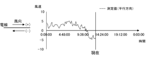
- FIG. 3A shows an example of time-series data of the parallel direction component (hereinafter referred to as “measured value (parallel direction)”) in a certain span, obtained by the wind condition information providing apparatus 100 as described above.
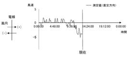
- FIG. 3B shows an example of time-series data of the orthogonal direction component (hereinafter referred to as “measured value (orthogonal direction)”) in the above span, which is obtained by the wind condition information providing apparatus 100.
- the horizontal axis of the graph shown in each figure is time, and the vertical axis is wind speed (m/s).
- the wind condition information providing device 100 provides (sends) the current wind condition of the span determined as above to the flight control device 300. Further, the wind condition information providing device 100 predicts the future wind conditions of the span using the time series data of the wind conditions of the span obtained as described above, and controls the operation of the predicted wind conditions of the span. Provide (send) to the device 300.
- the wind condition information providing device 100 calculates the above forecast based on the scheduled flight area (scheduled flight airspace) of the unmanned aircraft 200, which is obtained from weather information obtained from a weather information providing organization such as the Japan Weather Association (registered trademark). Forecast values (actual values may also be used) of the target wind conditions over a wider range than the wind conditions for each span in a predetermined area near the power equipment that the unmanned aerial vehicle 200 is to patrol or inspect, etc. This is done by making corrections using the wind conditions obtained for the span. Specifically, the wind condition information providing device 100 first obtains time-series data of the wind conditions in the span obtained as described above (hereinafter referred to as "first time-series data") and weather information.
- first time-series data time-series data of the wind conditions in the span obtained as described above
- Approximate expression that expresses the correlation between the difference between the predicted wind condition value (actual value may also be used) and time series data (hereinafter referred to as "second time series data") and the value of the second time series data.
- second time series data time series data
- a linear approximation formula Hereinafter referred to as a “difference prediction formula.”
- the wind condition information providing device 100 predicts the future wind condition of the span by reflecting (adding) the difference obtained from the above-mentioned difference prediction formula to the predicted value of the wind condition obtained from the weather information. .
- the wind condition information providing device 100 is based on a database (for example, an equipment information database (equipment ledger database) managed by an administrator of power equipment such as an electric power company) that shows the installation status of the power transmission tower 2 and the power transmission line 3.
- a database for example, an equipment information database (equipment ledger database) managed by an administrator of power equipment such as an electric power company) that shows the installation status of the power transmission tower 2 and the power transmission line 3.
- a database for example, an equipment information database (equipment ledger database) managed by an administrator of power equipment such as an electric power company) that shows the installation status of the power transmission tower 2 and the power transmission line 3.
- a database for example, an equipment information database (equipment ledger database) managed by an administrator of power equipment such as an electric power company) that shows the installation status of the power transmission tower 2 and the power transmission line 3.
- Mutual conversion between wind conditions for each span determined as parallel and orthogonal components and wind conditions expressed in absolute direction (absolute direction with north as 0° (360°)
- FIG. 4A shows an example of a difference prediction formula for the parallel direction component of wind speed (hereinafter referred to as “difference prediction formula (parallel direction)").
- FIG. 4B shows an example of a difference prediction formula for orthogonal direction components of wind speed (hereinafter referred to as “difference prediction formula (orthogonal direction)").
- Fig. 5A shows that the difference calculated from the difference prediction formula (parallel direction) is reflected in the parallel direction forecast value of wind conditions (hereinafter referred to as “forecast value (parallel direction)”) obtained from weather information (
- forecast value (parallel direction) An example of time series data of a future parallel direction component (hereinafter referred to as “predicted value (parallel direction)") predicted by adding (addition) is shown below.
- FIG. 5B shows that the difference obtained from the differential prediction formula (orthogonal direction) is reflected (added) to the forecast value of wind conditions obtained from weather information (hereinafter referred to as “forecast value (orthogonal direction)").
- predicted values (orthogonal directions) An example of time-series data of future orthogonal direction components (hereinafter referred to as “predicted values (orthogonal directions)" predicted by this method is shown below.
- the flight control device 300 transmits the real-time wind conditions for each span and predicted values (future wind conditions) of the wind conditions received from the wind condition information providing device 100 to the unmanned aircraft 200 at any time.
- the flight control device 300 also updates the flight plan of the unmanned aircraft 200 and controls the flight of the unmanned aircraft 200 based on real-time wind conditions and predicted values of wind conditions (future wind conditions) for each span.
- a flight plan includes, for example, a flight route (including information such as departure point, stopover point, destination, flight altitude, etc.), departure date and time, time and date of transit points, date and time of arrival at destination, Includes flight time, possible flight time, remaining battery power (remaining amount of onboard fuel if the power unit is an internal combustion engine), identification markings, unmanned aircraft model, payload information, information on the person in charge of operation, etc.
- FIG. 6A is a diagram showing the main configuration of the wind condition information providing device 100.
- the wind condition information providing device 100 includes a processor 101, a main storage device 102 (memory), an auxiliary storage device 103 (external storage device), an input device 104, an output device 105, a communication device 106, and an optical An analysis unit 107 is provided. These are communicably connected via a bus, communication cable, or the like.
- the wind condition information providing apparatus 100 may be realized, in whole or in part, using virtual information processing resources, such as a virtual server provided by a cloud system.
- the processor 101 is, for example, a CPU (Central Processing Unit), MPU (Micro Processing Unit), GPU (Graphics Processing Unit), FPGA (Field Programmable Gate Array), ASIC (Application Specific Integrated Circuit), AI (Artificial Intelligence) chip, etc. It is configured using
- the main storage device 102 is a storage device used when the processor 101 executes a program, and includes, for example, ROM (Read Only Memory), RAM (Random Access Memory), nonvolatile memory (NVRAM (Non Volatile RAM)), etc. It is.
- the auxiliary storage device 103 is a device that stores programs and data, and includes, for example, an SSD (Solid State Drive), a hard disk drive, an optical storage device (CD (Compact Disc), DVD (Digital Versatile Disc), etc.). can do. Programs and data can be read into the auxiliary storage device 103 from a non-temporary recording medium or another information processing device equipped with a non-temporary storage device via a recording medium reading device or a communication device 106. . Programs and data stored in the auxiliary storage device 103 are read into the main storage device 102 at any time.
- an SSD Solid State Drive
- CD Compact Disc
- DVD Digital Versatile Disc
- the input device 104 is an interface that accepts input of information from the outside, and is, for example, a keyboard, mouse, touch panel, voice input device, etc.
- the output device 105 is an interface that outputs various information such as processing progress and processing results to the outside.
- the output device 105 is, for example, a display device that visualizes the above various information (liquid crystal monitor, LCD (Liquid Crystal Display), etc.), a device that converts the above various information into audio (sound output device (speaker, etc.)), It is a device (printing device, etc.) that converts various information into characters. Note that, for example, a configuration may be adopted in which the information processing device 10 inputs and outputs information to and from another device via the communication device 106.
- the input device 104 and the output device 105 constitute a user interface that realizes interaction processing (receiving information, providing information, etc.) with the user.
- the communication device 106 is a device that realizes communication with other devices via a communication network (LAN (Local Area Network), WAN (Wide Area Network), Internet, public communication network, dedicated line, etc.).
- the communication device 106 is a wired or wireless communication interface that realizes communication with other devices via a communication medium, and is, for example, a NIC (Network Interface Card), a wireless communication module, a USB module, etc. be.
- NIC Network Interface Card
- the optical analysis unit 107 is a device that measures the vibration state of a measurement point using DAS, and includes a vibration measurement device using C-OTDR and a signal processing circuit.
- the optical analysis unit 107 includes a CW (continuous wave) laser light source that generates optical pulses (laser light) input to the end face of the optical fiber 4a, an optical pulse generator, an optical amplifier, and optical equipment (optical detector, optical interference device). , including a signal processing circuit (phase calculation circuit, etc.).
- the optical analysis unit 107 and the optical fiber 4a are connected, for example, by optically connecting the emitting part of the laser light source of the optical analysis unit 107 to a connection port (socket) of the core wire of an OPGW provided in the substation. This is done by Therefore, there will be no impact on the power system, such as a power outage, when the connection is made.
- an operating system a file system, a DBMS (DataBase Management System) (relational database, NoSQL, etc.), a KVS (Key-Value Store), etc. may be installed in the wind condition information providing device 100.
- DBMS DataBase Management System
- NoSQL NoSQL
- KVS Key-Value Store
- wind condition information providing apparatus 100 can be performed by the processor 101 reading and executing programs stored in the main storage device 102, or by using the hardware (FPGA) constituting the wind condition information providing apparatus 100. , ASIC, AI chip, etc.) itself.
- the wind condition information providing device 100 stores various information (data) as, for example, a database table or a file managed by a file system.
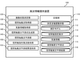
- FIG. 6B is a block diagram illustrating the main functions of the wind condition information providing device 100.
- the wind condition information providing device 100 includes a storage section 110, a vibration state measuring section 120, a span-specific wind condition acquisition section 130, a weather information acquisition section 135, a span-specific difference prediction formula generation section 140, It includes the functions of a span-by-span wind condition prediction section 145, a span-by-span current wind condition provision section 150, and a span-by-span wind condition prediction result provision section 155.
- the storage unit 110 stores vibration conditions for each measurement point 111, statistical models 112, current wind conditions for each span 113, weather information 114, difference prediction formulas for each span 115, and wind condition prediction results for each span 116. remember.
- the vibration state measurement unit 120 measures the vibration state of each measurement point using DAS, and manages the vibration state (vibration intensity, vibration frequency) measured for each measurement point as a vibration state 111 for each measurement point.
- the span-by-span wind condition acquisition unit 130 obtains the vibration state for each span of the power transmission line 3 (between adjacent transmission towers 2) (the vibration state for each measurement point in each span) based on the vibration state at each measurement point.
- the wind conditions for each span are obtained by inputting the obtained vibration state into the corresponding statistical model 112 (the above-mentioned statistical model generated for each wind speed range and each span).
- the span-by-span wind condition acquisition unit 130 manages the acquired wind condition time-series data (first time-series data) as the span-by-span current wind condition 113.
- the weather information acquisition unit 135 acquires weather information (latest weather information, past weather information) used for predicting wind conditions for each span via a communication network such as the Internet, from a website such as the Japan Weather Association (registered trademark). Obtained from weather information providers as needed.
- the weather information covers a wider area than the current wind conditions for each span in a predetermined area near the power equipment that the unmanned aerial vehicle 200 is to patrol or inspect in the area where the unmanned aerial vehicle 200 is scheduled to fly. Contains wind conditions and forecast values for wind conditions.
- the weather information acquisition unit 135 manages the acquired weather information as the weather information 114. Furthermore, the weather information acquisition unit 135 mutually converts the wind conditions in each span obtained as parallel direction components and orthogonal direction components to the wind conditions expressed in absolute azimuth.
- the span-by-span difference prediction formula generation unit 140 generates the above-described difference prediction formulas (difference prediction formula (parallel direction), difference prediction formula (orthogonal direction)) for each span.
- the per-span difference prediction formula generation unit 140 manages the generated difference prediction formula for each span (for each measurement point) as a per-span difference prediction formula 115 .
- the span-by-span wind condition prediction unit 145 reflects the difference obtained by the above-mentioned difference prediction formula (difference prediction formula (parallel direction), difference prediction formula (orthogonal direction)) to the wind condition forecast value obtained from the weather information. By doing so, the wind conditions for each span can be predicted.
- the span-by-span wind condition prediction unit 145 manages the predicted wind conditions for each span as a span-by-span wind condition prediction result 116.
- the current wind condition provision unit 150 for each span provides (sends) the current wind condition 113 for each span managed by the wind condition acquisition unit 130 for each span to the flight control device 300.
- the span-by-span wind condition prediction result providing unit 155 provides (sends) the span-by-span wind condition prediction result 116 managed by the span-by-span wind condition prediction unit 145 to the flight control device 300.
- the OPGW 4 optical fiber 4a
- the wind conditions for each altitude are calculated by converting the current wind conditions for each span 113 and the predicted wind conditions for each span 116, taking into account the influence of the wind gradient.
- the determined wind conditions for each altitude may be provided to the flight control device 300.
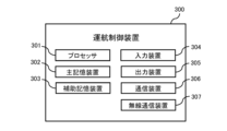
- FIG. 7A is a diagram showing the main configuration of the flight control device 300.
- the flight control device 300 includes a processor 301, a main storage device 302 (memory), an auxiliary storage device 303 (external storage device), an input device 304, an output device 305, a communication device 306, and a wireless communication device. 307. These are communicably connected via a bus, communication cable, or the like.
- the processor 301, the main storage device 302, the auxiliary storage device 303, the input device 304, the output device 305, and the communication device 306 are the processor 101, the main storage device 102, and the communication device 306 of the wind condition information providing device 100, respectively. Since they are the same as the auxiliary storage device 103, input device 104, output device 105, and communication device 106, their explanation will be omitted.
- the wireless communication device 307 includes a wireless communication module that performs analog or digital wireless communication using radio waves of a predetermined frequency, and transmits and receives various information to and from the unmanned aircraft 200.
- the wireless communication device 307 also uses a telemetering mechanism to provide information about the unmanned aircraft 200 (for example, various sensors (satellite positioning device, acceleration sensor, speed sensor, geomagnetic sensor, microwave radar, microwave radar, LiDAR (Light)). Detection And Ranging), measured values of an EKF device (extended Kalman filter), images or video captured by a camera mounted on the unmanned aerial vehicle 200) are acquired at any time (in real time, at scheduled times, at scheduled times, etc.).
- the flight control device 300 stores various information (data) as, for example, a database table or a file managed by a file system.
- FIG. 7B is a block diagram illustrating the main functions of the flight control device 300.
- the operation control device 300 includes a storage unit 310, a current wind condition acquisition unit for each span 320, a prediction result acquisition unit for wind conditions for each span 330, a current wind condition transmission unit for each span 335, a current wind condition transmission unit for each span 335, and a current wind condition transmission unit for each span.
- Each function of the wind condition prediction result transmission section 340, unmanned aircraft information acquisition section 345, flight plan management section 350, flight plan transmission section 355, flight control instruction transmission section 360, other system cooperation section 365, and flight monitoring section 370 Be prepared.
- the storage unit 310 stores current wind conditions for each span 311, wind condition prediction results for each span 312, flight plans 313, unmanned aircraft information 314, flight control instructions 315, and other system acquisition information 316. .
- the span-specific current wind condition acquisition unit 320 receives the span-specific current wind condition 113 sent from the wind condition information providing device 100, and converts the span-specific current wind condition 113 into the span-specific current wind condition 311. Manage as.
- the span-by-span wind condition prediction result acquisition unit 330 receives the span-by-span wind condition prediction result 116 sent from the wind condition information providing device 100, and acquires the span-by-span wind condition prediction result 116 from the span-by-span wind condition prediction result. It is managed as a situation prediction result 312.
- the current wind condition transmission unit for each span 335 transmits the current wind condition for each span 311 to the unmanned aircraft 200.
- the span-by-span wind condition prediction result transmitting unit 340 transmits the span-by-span wind condition prediction result 312 to the unmanned aircraft 200.
- the unmanned aircraft information acquisition unit 345 receives information regarding the current situation of the unmanned aircraft 200 (current position, acceleration, speed, flight direction, flight attitude, remaining battery power, photographed image or photographed video, etc.), and transmits the received information. It is managed as unmanned aircraft information 314.
- the flight plan management unit 350 manages the flight plan set for the unmanned aircraft 200 as a flight plan 313.
- the flight plan management section 35 receives information necessary for setting the flight plan 313, for example, via the other system cooperation section 365 or the user interface, and formulates (generates) a flight plan based on the received information.
- the flight plan management unit 35 also receives the current wind conditions for each span 311, the predicted wind conditions for each span 312, the unmanned aircraft information 314, and information provided from the other system cooperation unit 365 (for example, information obtained by rain cloud radar, etc.).
- a flight plan 313 is drawn up in consideration of the weather information for each region.
- the flight plan management unit 35 receives the wind condition prediction results for each span 312, the unmanned aircraft information 314, and information provided from the other system cooperation unit 365 (for example, weather information for each region acquired by rain cloud radar etc.)
- the flight plan 313 is updated from time to time in consideration of the above.
- the flight plan management unit 35 determines whether the unmanned aircraft 200 is safe based on the current wind conditions 311 for each span, weather information provided from the other system cooperation unit 365 (other system acquisition information 316), and unmanned aircraft information 314. Wind conditions that would affect the flight (wind conditions that deviate from the operational limits set for the unmanned aircraft 200) or weather conditions that are currently being encountered, or wind conditions that would affect safe flight if the flight continues. If it is determined that there is a possibility of encountering a situation or weather, the flight plan 313 is changed to a flight plan 313 that allows the unmanned aircraft 200 to fly safely (a flight plan that selects a flight route that does not deviate from operational restrictions). .
- the flight plan management unit 35 may create a flight plan 313 that can avoid the other aircraft. etc., the flight plan 313 is changed to a flight plan 313 that allows the unmanned aircraft 200 to fly safely.
- the unmanned aircraft 200 is currently encountering wind conditions or weather conditions that would impede safe flight, or if it continues to fly as it is, there is a possibility that it will encounter wind conditions or weather conditions that would impair safe flight.
- the wind speed exceeds a preset limit value at which the unmanned aircraft 200 can fly (for example, the limit value of the wind speed acting on the unmanned aircraft 200 in flight (wind resistance, operational limit)) (or In other cases, if the flight continues to the destination, the battery level may fall below the lower limit required for the flight.
- the flight plan 313 that allows safe flight includes, for example, a flight plan in which the flight distance does not exceed the cruising range determined from the relationship between the current wind conditions, predicted wind conditions, and the current battery level;
- the flight plan management unit 350 may accept corrections to the changed flight plan from the user, for example, via a user interface. Further, for example, the flight plan management unit 350 may apply the changed flight plan to the actual flight of the unmanned aircraft 200 after receiving the user's intention to approve the changed flight plan via the user interface. Good too.
- the flight plan management unit 350 takes into account the current battery level and current or future wind conditions based on the current wind conditions for each span 311, the predicted wind conditions for each span 312, and the unmanned aircraft information 314. The possible flight distance and flight time in that case may be determined, and the determined results may be presented to the user via a user interface. Further, the flight plan management unit 350 may notify (transmit) the obtained result to the unmanned aircraft 200.
- the flight plan transmitting unit 355 shown in FIG. 7B transmits the flight plan 313 to the unmanned aircraft 200 at any time.
- the flight control instruction transmitting unit 360 also provides flight control instructions for the unmanned aircraft 200 based on, for example, the current wind conditions for each span 311, the predicted wind conditions for each span 312, the unmanned aircraft information 314, and the latest flight plan 313. 315 and transmits the generated flight control instruction 315 to the unmanned aircraft 200.
- the other system cooperation unit 365 communicates with other systems (for example, an operation management system operated by NEDO (registered trademark) (New Energy and Industrial Technology Development Organization), a weather information providing organization, etc.), and Information that should be referred to when creating a plan 313 or generating flight control instructions 315 (flight plans and flight restriction information for other aircraft (unmanned aircraft and manned aircraft), etc.) and the latest weather information (current weather information for each region, etc.) Get (receive) the latest forecast).
- the other system cooperation unit 365 manages the acquired information as other system acquisition information 316.
- the other system cooperation unit 365 transmits information regarding the operation of the unmanned aircraft 200 (for example, current wind conditions for each span 311, predicted wind conditions for each span 312, flight plan 313, unmanned aircraft information 314, etc.) to other systems. Provide (send) information from time to time. By providing this information to other systems, the accuracy of the information provided by the flight management system can be improved, and the safety of aircraft operations can be increased.
- information regarding the operation of the unmanned aircraft 200 for example, current wind conditions for each span 311, predicted wind conditions for each span 312, flight plan 313, unmanned aircraft information 314, etc.
- the flight monitoring unit 370 compares the most recently acquired unmanned aircraft information 314 with the flight plan 313 and monitors the flight status of the unmanned aircraft 200 and whether the flight according to the flight plan 313 has been completed.
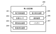
- FIG. 8A is a diagram showing the main configuration of the unmanned aircraft 200.
- the unmanned aircraft 200 includes a flight control system 201 (FCS: Flight Control System, FCU: Flight Control Unit), various sensors 202, an inertial navigation device 203 (EKF: Extended Kalman Filter), and a satellite positioning device 204. , a thrust generator 205, a communication device 206, and a battery 207.
- FCS Flight Control System
- FCU Flight Control Unit
- EKF Extended Kalman Filter
- the flight control device 201 is configured using an information processing device such as a microcomputer, and controls the flight and various operations of the unmanned aircraft 200.
- the various sensors 202 are, for example, an acceleration sensor, a speed sensor, a geomagnetic sensor, a microwave radar, a microwave radar, a LiDAR, an EKF device, a camera, etc.
- the inertial navigation device 203 determines the current position by performing self-position estimation processing (for example, self-position estimation processing using an extended Kalman filter) based on information (acceleration, angular velocity, etc.) measured in real time by various sensors 202. Output the current position.
- self-position estimation processing for example, self-position estimation processing using an extended Kalman filter
- information acceleration, angular velocity, etc.
- the satellite positioning device 204 uses a satellite positioning system such as GNSS (Global Navigation Satellite System) to obtain the current position by independent positioning or relative positioning (D-GPS positioning, RTK (Real Time Kinematic), etc.). It is a device that receives positioning signals sent from positioning satellites such as GPS satellites, calculates the current position, and inputs the calculated current position to the flight control device 201.
- GNSS Global Navigation Satellite System
- RTK Real Time Kinematic
- the thrust generator 205 includes a power motor and a motor control device (ESC: Electronic Speed Controller).
- ESC Electronic Speed Controller
- the communication device 206 performs bidirectional wireless communication with the flight control device 300.
- the battery 207 is, for example, a lithium ion polymer secondary battery, and supplies driving power to each component of the unmanned aircraft 200.
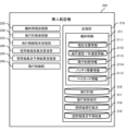
- FIG. 8B is a block diagram illustrating the main functions of the unmanned aircraft 200.
- the unmanned aircraft 200 includes a storage unit 210, an aircraft information transmitting unit 220, a flight plan receiving unit 230, a flight control instruction receiving unit 235, a current wind condition receiving unit 240 for each span, and a wind condition receiving unit 240 for each span. It has the functions of a prediction result receiving section 245 and a flight control section 250.
- the storage unit 210 stores aircraft information 211 (current position information 2111 (latitude, longitude, altitude), flight speed/acceleration information 2112, flight course information 2113, remaining battery level information 2114, payload information) acquired in real time about the unmanned aircraft 200. 2115), a flight plan 216, flight control instructions 217, current wind conditions for each span 218, and predicted wind conditions for each span 219.
- aircraft information 211 current position information 2111 (latitude, longitude, altitude), flight speed/acceleration information 2112, flight course information 2113, remaining battery level information 2114, payload information
- 2115 a flight plan 216
- flight control instructions 217 current wind conditions for each span 218, and predicted wind conditions for each span 219.
- the aircraft information transmitting unit 220 transmits the aircraft information 211 to the flight control device 300 at any time (in real time, on schedule, at scheduled time, etc.). Note that the aircraft information 211 transmitted by the aircraft information transmitter 220 to the flight control device 300 is managed as unmanned aircraft information 314 in the flight control device 300.
- the flight plan receiving unit 230 receives the flight plan 313 sent from the flight control device 300 and manages the received flight plan 313 as a flight plan 216.
- the flight control instruction receiving unit 235 receives the flight control instruction 315 sent from the flight control device 300 and manages the received flight control instruction 315 as a flight control instruction 217.
- the current wind condition for each span receiving unit 240 receives the current wind condition for each span 311 sent from the flight control device 300, and manages the received current wind condition for each span 311 as the current wind condition for each span 218. do.
- the span-by-span wind condition prediction result receiving unit 245 receives the span-by-span wind condition prediction result 312 sent from the flight control device 300, and converts the received span-by-span wind condition prediction result 312 into a span-by-span wind condition prediction result. It is managed as a result 219.
- the flight control unit 250 uses a remote control method to passively control the flight of the unmanned aircraft 200 according to the flight control instruction 217 from the operation control device 300, or autonomously controls the flight of the unmanned aircraft 200 based on the aircraft information 211.
- the flight of the unmanned aircraft 200 is controlled by one of the autonomous control methods.
- the flight control unit 250 controls the flight of the unmanned aircraft 200 according to the flight plan 216.
- the flight control instruction 217 can be given priority over the flight plan 216, and in that case, upon receiving the flight control instruction 217, the flight control unit 250 controls the flight of the unmanned aircraft 200 according to the received flight control instruction 217. control.
- the flight control unit 250 controls the flight of the unmanned aircraft 200 based on, for example, the current wind conditions for each span 218 and the predicted wind conditions for each span 219. For example, the flight control unit 250 determines, based on the current wind conditions 311 for each span and the unmanned aircraft information 314, that the unmanned aircraft 200 is currently encountering wind conditions that are suitable for safe flight, or that the unmanned aircraft 200 continues to fly. If it is determined that there is a possibility that the unmanned aerial vehicle 200 will encounter wind conditions that would impede safe flight, the unmanned aerial vehicle 200 is controlled to select a flight path or flight speed that allows the unmanned aerial vehicle 200 to fly safely. do.
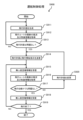
- FIG. 9 is a flowchart illustrating an example of a process (hereinafter referred to as "operation control process S900") performed by the flight control device 300 during operation of the unmanned aircraft 200.
- operation control process S900 will be described below with reference to the same figure.
- the flight plan management unit 350 of the flight control device 300 generates the flight plan 313 (S911).
- the current wind condition acquisition unit 320 for each span of the flight control device 300 obtains the latest wind conditions for the flight route in the flight plan 313 (wind conditions for the spans along the flight route (current wind conditions for each span 311, The span-by-span wind condition prediction result 312)) is acquired from the wind condition information providing device 100, and the other system cooperation unit 365 of the flight control device 300 acquires the latest weather information from other systems (S912).
- the flight plan management unit 350 of the flight control device 300 determines whether there is any problem with the flight plan 313 drawn up in S911 (whether a safe flight can be ensured) based on the acquired wind conditions and weather information (S913 ). If there is a problem with the flight plan 313 drawn up in S911 (S913: NO), the process returns to S911, and the flight plan management unit 350 reconsiders the flight plan 313 while taking into account the acquired wind conditions and weather information. If there is no problem with the flight plan 313 drawn up in S911 (S913: YES), the process proceeds to S914.
- the flight plan transmitting unit 355 of the operation control device 300 transmits the flight plan 313 created in S911 and the flight control instruction 315 according to the flight plan 313 to the unmanned aircraft 200.
- the unmanned aircraft information acquisition unit 345 of the flight control device 300 receives unmanned aircraft information 314 from the unmanned aircraft 200 at any time (S915).
- the current wind condition acquisition unit 320 for each span of the flight control device 300 also acquires the latest wind conditions for the flight route in the flight plan 313 (wind conditions for the spans along the flight route (current wind conditions for each span 311, current wind conditions for each span 311, The hourly wind condition prediction result 312)) is acquired from the wind condition information providing device 100, and the other system cooperation unit 365 of the flight control device 300 acquires the latest weather information for the flight planned area from other systems (S916). ).
- the flight plan management unit 350 of the operation control device 300 determines whether the unmanned aircraft 200 is flying safely and whether it can maintain a safe flight even if it continues to fly. (S917) is whether the current situation exceeds or is likely to exceed the wind speed of the unmanned aircraft 200, whether there is enough remaining battery power to reach the destination, etc. (S917). If it is determined that a safe flight cannot be maintained (S917: NO), the flight plan management unit 350 reconsiders the flight plan 313 in consideration of the acquired wind conditions and weather information (S920), and then the process returns to S914. . On the other hand, if the flight plan management unit 350 determines that a safe flight can be maintained (S917: YES), the process proceeds to S918.
- the unmanned aircraft information acquisition unit 345 receives the latest unmanned aircraft information 314 from the unmanned aircraft 200.
- the flight monitoring unit 370 of the unmanned aircraft 200 compares the latest unmanned aircraft information 314 with the flight plan 313, and determines whether the flight of the unmanned aircraft 200 has ended (the flight according to the flight plan 313 has been completed). Determine. If the flight monitoring unit 370 determines that the flight of the unmanned aircraft 200 has not ended (S919: NO), the process returns to S915. On the other hand, if the flight monitoring unit 370 determines that the flight of the unmanned aircraft 200 has ended (S919: YES), the operation control process S900 ends.
- the unmanned aircraft 200 may perform all or part of the functions of the flight control processing S900 described above. Further, in the above, the flight control device 300 acquires weather information from other systems, but the flight control device 300 may acquire weather information from the wind condition information providing device 100.
- the navigation support system 1 of the present embodiment measures the diameter of the power transmission line 3 based on the vibration state acquired by DAS at measurement points set along the optical fiber attached along the power transmission line.
- a flight plan is generated based on the acquired wind conditions, and the generated flight plan or a flight control instruction based on the flight plan is transmitted to the unmanned aircraft 200. Therefore, the local wind conditions in the span can be efficiently acquired.
- the flight support system 1 since the flight support system 1 generates a flight plan based on the local wind conditions at the site where the unmanned aircraft 200 actually flies, the flight support system 1 generates a flight plan based only on the weather information provided by a weather information provider, etc. It is possible to generate a flight plan based on highly accurate wind conditions that reflect the effects of the topography of the site. Therefore, the unmanned aircraft 200 can be operated safely.
- the navigation support system 1 calculates future forecasts based on the correlation between past time-series data of forecast values of wind conditions provided by weather information providing organizations and past time-series data of wind conditions in spans. By correcting the values, the future wind conditions of the span are predicted, and a flight plan is generated based on the predicted wind conditions. Therefore, local wind conditions in the span of the power transmission line 3 can be predicted efficiently. Furthermore, since the flight support system generates a flight plan based on predicted values of local wind conditions at the site where the unmanned aircraft 200 actually flies, the flight plan is generated based only on weather information provided by a weather information provider. Compared to the case of generating a flight plan, it is possible to generate a flight plan based on highly accurate wind conditions that reflect the influence of the topography of the site. Therefore, the unmanned aircraft 200 can be operated safely.
- the flight support system 1 selects a flight route that does not deviate from the operational limits and generates a flight plan. Therefore, the unmanned aircraft 200 can be operated safely.
- the flight support system 1 generates a flight plan based on the possible cruising distance determined from the relationship between the current or predicted wind conditions and the remaining battery power. Therefore, a flight plan can be appropriately generated within the cruising range, and the unmanned aircraft 200 can be operated safely.
- 1 Operation support system 2 Power transmission tower, 3 Power transmission line, 4 OPGW, 4a Optical fiber, 6 Substation, 100 Wind condition information providing device, 107 Optical analysis unit, 110 Storage unit, 111 Vibration status for each measurement point, 112 Statistical model , 113 Current wind condition for each span, 114 Weather information, 115 Difference prediction formula for each span, 116 Wind condition prediction result for each span, 120 Vibration condition measurement unit, 130 Wind condition acquisition unit for each span, 135 Weather information acquisition unit , 140 Span-specific difference prediction formula generation unit, 145 Span-specific wind condition prediction unit, 150 Span-specific current wind condition provision unit, 155 Span-specific wind condition prediction result provision unit, 200 Unmanned aerial vehicle, 210 Storage unit, 211 Aircraft information, 2114 Battery remaining information, 216 Flight plan, 217 Flight control instructions, 218 Current wind conditions for each span, 219 Wind condition prediction results for each span, 230 Flight plan receiving section, 235 Flight control instruction receiving section, 240 Radius Current wind condition reception unit for each span, 2
Abstract
The present invention efficiently acquires local wind conditions to safely operate an unmanned aircraft. This operation assistance system for unmanned aircraft is configured using an optical analysis unit, an information processing device, and a communication device that wirelessly communicates with an unmanned aircraft. This operation assistance system acquires the current wind conditions in the span of a power transmission line or distribution line on the basis of the vibration state acquired by distributed acoustic sensing (DAS) at measurement points set along an optical fiber installed along the power transmission line or distribution line, generates a flight plan on the basis of the acquired wind conditions, and transmits the generated flight plan or flight control instructions based on the flight plan to the unmanned aircraft. This operation assistance system also acquires forecast values of weather information in the area where the unmanned aircraft is scheduled to fly, which are provided by a weather information provider, and predicts future wind conditions in the span by correcting future forecast values on the basis of the correlation between the time-series data of the forecast values and the time-series data of the wind conditions in the span.
Description
本発明は、無人航空機の運航支援システム及び運航支援方法に関する。
The present invention relates to an unmanned aircraft operation support system and an operation support method.
近年、業務の効率化や省力化、安全性の向上等を目的として、送電線等の電力設備の巡視や点検業務への無人航空機(いわゆるドローン)の導入が進められている。
In recent years, unmanned aerial vehicles (so-called drones) have been introduced for patrolling and inspecting power equipment such as power transmission lines, with the aim of streamlining operations, saving labor, and improving safety.
例えば、特許文献1には、送電線への接近樹木の点検等を自動的に行うことを目的として構成された無人航空機を用いた送電線点検システムについて記載されている。上記の送電線点検システムは、自律飛行しつつ送電線の点検箇所まで飛行するための飛行制御系及び点検箇所の画像並びに距離測定データを含む各種情報を収集するための情報収集系を備える無人ヘリコプタと、無人ヘリコプタの飛行を制御するとともに無人ヘリコプタからの各種情報を収集して処理する飛行制御/情報収集系を備える管制センターと、無人ヘリコプタの情報収集系により収集された点検箇所の画像及び距離測定データから3次元画像を作成し、作成した3次元画像を処理し、処理された3次元画像に基づいて点検箇所の送電線に異常があるか否かを点検する接近樹木等点検手段と、接近樹木等点検手段における点検に使用される各種データが記憶された記憶装置と、を備える。
For example, Patent Document 1 describes a power transmission line inspection system using an unmanned aerial vehicle configured to automatically inspect trees approaching power lines. The above-mentioned power transmission line inspection system is an unmanned helicopter that is equipped with a flight control system for flying autonomously to inspection points on power lines and an information collection system for collecting various information including images of inspection points and distance measurement data. , a control center equipped with a flight control/information collection system that controls the flight of the unmanned helicopter and collects and processes various information from the unmanned helicopter, and images and distances of inspection points collected by the unmanned helicopter's information collection system. An approaching tree inspection means for creating a three-dimensional image from the measurement data, processing the created three-dimensional image, and checking whether there is an abnormality in the power transmission line at the inspection point based on the processed three-dimensional image; and a storage device storing various data used for inspection by the approaching tree inspection means.
無人航空機は飛行中に風の影響を受けやすく、とくに強風時は姿勢の維持が困難となる。そのため、従来より、飛行前や飛行中に飛行計画における気象状況を正確に把握もしくは正確に予測した上で飛行計画を立案するための仕組みが提案されている。
Unmanned aircraft are easily affected by wind during flight, and it is especially difficult to maintain their posture during strong winds. Therefore, conventionally, mechanisms have been proposed to formulate a flight plan after accurately grasping or accurately predicting the weather conditions for the flight plan before or during the flight.
例えば、特許文献2には、無人航空機を安全に飛行させることを目的として構成された気象観測システム及び飛行管制システムについて記載されている。上記の気象観測システムは、ドローンをほぼ真上垂直方向又は真下垂直方向に飛行させ、飛行中のドローンの制御情報から風向及び風速を計測する。また、上記の飛行管制システムは、第一のドローンを飛行させることにより飛行計画に関連する風向及び風速の情報を取得し、風向及び風速の情報を参考にして第二のドローンの飛行計画を選定する。
For example, Patent Document 2 describes a weather observation system and a flight control system configured for the purpose of safely flying an unmanned aircraft. The above-mentioned weather observation system allows a drone to fly in a vertical direction almost directly above or in a vertical direction directly below, and measures wind direction and wind speed from control information of the flying drone. In addition, the above flight control system acquires information on wind direction and wind speed related to the flight plan by flying the first drone, and selects a flight plan for the second drone by referring to the information on the wind direction and wind speed. do.
また特許文献3には、無人航空機の安全を図ることを目的として構成された無人航空機管理装置について記載されている。無人航空機管理装置は、無人航空機の飛行予定経路を取得し、取得した飛行予定経路を含む領域における、飛行予定時刻の気象を特定する気象情報を取得し、飛行予定経路と気象情報とに基づき、無人航空機の実際の飛行経路を予測する。
Further, Patent Document 3 describes an unmanned aircraft management device configured for the purpose of ensuring the safety of unmanned aircraft. The unmanned aircraft management device acquires the scheduled flight route of the unmanned aircraft, acquires weather information that specifies the weather at the scheduled flight time in an area including the acquired scheduled flight route, and based on the scheduled flight route and the weather information, Predict the actual flight path of an unmanned aircraft.
送電線や配電線は、山間部等の起伏が多い地域等、風況(風向、風速)が局地的に異なる地域に設置されていることも多く、こうした地域を通る送電線や配電線の巡視や点検を無人航空機を用いて行う場合には、径間毎等の局地的な風況を精度よく取得もしくは予測して無人航空機を安全に飛行させる必要がある。
Power transmission lines and distribution lines are often installed in areas with locally varying wind conditions (wind direction, wind speed), such as mountainous areas and other hilly areas. When conducting patrols and inspections using unmanned aerial vehicles, it is necessary to accurately obtain or predict local wind conditions for each span, etc., so that the unmanned aerial vehicle can fly safely.
ここで例えば、上記の特許文献2では、飛行中のドローンの制御情報から風向及び風速を計測するが、計測のたびにドローンをほぼ真上垂直方向又は真下垂直方向に飛行させる必要があり、そのために余分な電力や燃料が消費され、巡視や点検のための飛行時間が短くなる。また、例えば、特許文献3では、気象庁が提供する気象情報や風況センサ等の観測機器によって測定された情報を利用するため、径間毎等の局地的な風況を取得することはできない。また、風況センサ等の観測機器は一般に高価である上、電源の確保や通信機器の設置、定期的な保守や交換等、様々な準備や作業が必要になる。
For example, in Patent Document 2 mentioned above, the wind direction and wind speed are measured from the control information of the drone in flight, but the drone needs to fly almost vertically above or vertically below each time the measurement is performed. This consumes extra power and fuel and reduces flight time for patrols and inspections. Furthermore, for example, Patent Document 3 uses weather information provided by the Japan Meteorological Agency and information measured by observation equipment such as wind condition sensors, so it is not possible to obtain local wind conditions for each span. . Furthermore, observation equipment such as wind condition sensors are generally expensive and require various preparations and work, such as securing a power source, installing communication equipment, and regular maintenance and replacement.
本発明は、このような背景に鑑みてなされたものであり、局地的な風況を効率よく取得して無人航空機の安全な運航を支援することが可能な、無人航空機の運航支援システム及び運航支援方法を提供することを目的とする。
The present invention was made in view of this background, and provides an unmanned aircraft operation support system and an unmanned aircraft operation support system that can efficiently acquire local wind conditions and support the safe operation of unmanned aircraft. The purpose is to provide a navigation support method.
上記課題を解決するための手段の一つは、無人航空機の運航支援システムであって、光解析ユニット、情報処理装置、及び無人航空機と無線通信する通信装置を用いて構成され、送電線又は配電線に沿って付設される光ファイバに沿って設定された測定点についてDAS(Distributed Acoustic Sensing)により取得される振動状態に基づき前記送電線又は配電線の径間の現在の風況を取得し、取得した前記風況に基づき飛行計画を生成し、生成した飛行計画又は前記飛行計画に基づく飛行制御指示を前記無人航空機に送信する。
One of the means for solving the above problems is an unmanned aircraft operation support system that is configured using an optical analysis unit, an information processing device, and a communication device that wirelessly communicates with the unmanned aircraft, and is Obtaining the current wind conditions in the span of the power transmission line or distribution line based on the vibration state obtained by DAS (Distributed Acoustic Sensing) at measurement points set along the optical fiber installed along the electric wire, A flight plan is generated based on the acquired wind conditions, and the generated flight plan or a flight control instruction based on the flight plan is transmitted to the unmanned aircraft.
その他、本願が開示する課題、及びその解決方法は、発明を実施するための形態の欄、及び図面により明らかにされる。
Other problems disclosed in the present application and methods for solving the problems will be made clear by the detailed description section and the drawings.
本発明によれば、局地的な風況を効率よく取得して無人航空機を安全に運航することができる。
According to the present invention, it is possible to efficiently acquire local wind conditions and safely operate an unmanned aircraft.
本明細書及び添付図面の記載により、少なくとも以下の事項が明らかとなる。以下、本発明をその一実施形態に即して添付図面を参照しつつ説明する。
At least the following matters will become clear from the description of this specification and the attached drawings. DESCRIPTION OF THE PREFERRED EMBODIMENTS The present invention will be described below based on one embodiment thereof with reference to the accompanying drawings.
図1に本発明の一実施形態として説明する無人航空機の運航支援システム(以下、「運航支援システム1」と称する。)の概略的な構成を示している。同図に示すように、運航支援システム1は、変電所6等に設けられる風況情報提供装置100と、送電鉄塔2に架設されている架空送電線(電柱等に架設された配電線でもよい。以下、「送電線3」と称する。)に沿って飛行することにより電力設備(送電鉄塔2、送電線3、変電設備4等)の巡視や点検等の業務を行う無人航空機200(ドローン)と、無人航空機200と通信し、無人航空機200の監視や各種情報の提供、運航制御等を行う情報処理装置である運航制御装置300と、を含む。
FIG. 1 shows a schematic configuration of an unmanned aircraft operation support system (hereinafter referred to as "operation support system 1") described as an embodiment of the present invention. As shown in the figure, the navigation support system 1 includes a wind condition information providing device 100 installed at a substation 6, etc., and an overhead power transmission line installed on a power transmission tower 2 (a distribution line installed on a utility pole etc. may also be used). An unmanned aerial vehicle 200 (drone) that performs duties such as patrolling and inspecting power equipment (power transmission towers 2, power transmission lines 3, substation equipment 4, etc.) by flying along power transmission lines (hereinafter referred to as "power transmission lines 3"). and an operation control device 300, which is an information processing device that communicates with the unmanned aircraft 200, monitors the unmanned aircraft 200, provides various information, controls the operation, etc.
風況情報提供装置100は、送電線3に架設されているOPGW4(optical ground wire)(光ファイバ複合架空地線)の光ファイバ4aをセンサとして用い、光ファイバ4aに沿った複数の点(以下、各点のことを「測定点」と称する。)の夫々における光ファイバ4aの伸縮に基づく振動状態(振動強度、振動周波数)を測定する技術(分布型多点振動測定法(以下、「DAS」(Distributed Acoustic Sensing)と称する。)により、各測定点の振動状態に基づき各測定点における風況(風向、風速)を取得する。尚、DASは、例えば、C-OTDR(Coherent detection Optical Time Domain Reflectometer)の原理により各測定点の振動状態を取得する。
The wind condition information providing device 100 uses an optical fiber 4a of an OPGW4 (optical ground wire) installed on a power transmission line 3 as a sensor, and detects multiple points (hereinafter referred to as , each point is referred to as a "measurement point.") A technique for measuring the vibration state (vibration intensity, vibration frequency) based on the expansion and contraction of the optical fiber 4a (distributed multipoint vibration measurement method (hereinafter referred to as "DAS")). (referred to as "Distributed Acoustic Sensing"), the wind conditions (wind direction, wind speed) at each measurement point are acquired based on the vibration state of each measurement point. The vibration state of each measurement point is acquired using the principle of Domain Reflectometer.
図2は、風況情報提供装置100が各測定点の振動状態を測定する仕組みを説明する図である。同図に示すように、風況情報提供装置100は、光ファイバ4aの端面から光パルス(レーザーパルス。以下、「入射光」とも称する。)を入射し、各測定点における、光パルスの後方散乱光の位相差の変化速度(≒伸縮周波数)を測定する。尚、上記の位相差は後方散乱光どうしの干渉による強度変化から推定する。そして、風況情報提供装置100は、測定した上記変化速度に基づき、各測定点における光ファイバ4aの縦波及び横波の振動周波数(例えば、最大10kHzの範囲の振動周波数)を求める。また、風況情報提供装置100は、振動周波数毎の位相差に基づき、各測定点における振動強度(スペクトル強度、振動振幅)を求める。尚、風況情報提供装置100は、入射光を上記端面に入射した時点から戻り光を受光した時点までの経過時間に基づき、各測定点の位置(上記端面からの距離)を求める。
FIG. 2 is a diagram illustrating how the wind condition information providing device 100 measures the vibration state of each measurement point. As shown in the figure, the wind condition information providing apparatus 100 inputs a light pulse (laser pulse; hereinafter also referred to as "incident light") from the end face of an optical fiber 4a, and Measure the rate of change in the phase difference of scattered light (≒stretching frequency). Note that the above phase difference is estimated from intensity changes due to interference between backscattered lights. Then, the wind condition information providing device 100 determines the vibration frequencies of the longitudinal waves and transverse waves of the optical fiber 4a at each measurement point (for example, vibration frequencies in a maximum range of 10 kHz) based on the measured rate of change. Furthermore, the wind condition information providing device 100 determines the vibration intensity (spectral intensity, vibration amplitude) at each measurement point based on the phase difference for each vibration frequency. Note that the wind condition information providing device 100 determines the position of each measurement point (distance from the end surface) based on the elapsed time from the time when the incident light enters the end surface to the time when the returned light is received.
上記の測定点は、例えば、光ファイバに沿って送電鉄塔2の径間よりも短い所定間隔d(m)毎に設定される(0(m)、d(m)、・・・・、N(m)、N+d(m)、N+2d(m))。例えば、所定間隔dを5(m)とし、最長70(km)の範囲に測定点を設定した場合には、光ファイバに沿って14000点程度の測定点が設定される。
The above measurement points are set, for example, at predetermined intervals d (m) shorter than the span of the power transmission tower 2 along the optical fiber (0 (m), d (m), ..., N (m), N+d(m), N+2d(m)). For example, if the predetermined interval d is 5 (m) and measurement points are set in a range of up to 70 (km), about 14,000 measurement points are set along the optical fiber.
風況情報提供装置100は、各測定点の振動状態に基づき、送電線3の径間(隣接する送電鉄塔2の間)毎の振動状態を取得する。ここで例えば、非特許文献1(「強風時における送電線の振動特性に関する研究」,都市災害管理学,稲吉 健,九州大学,修士論文一覧,URL:https://www.hues.kyushu-u.ac.jp/education/student/pdf/2003/2HE02019E.pdf(令和4年5月18日検索))に記載されているように、径間における光ファイバ4aの振動状態は、径間における風況との間に一定の相関を有する。そのため、上記相関を表す統計モデルを予め生成しておき、生成した統計モデルに径間の測定点について取得した振動状態を入力することにより、径間の風況を取得することができる。尚、光ファイバ4aの振動状態の振動モード(固有振動モード)は風速によって異なる(風速の変化に対して振動状態は非線形となる)ので、上記の統計モデルは風速の範囲毎に生成する(例えば、風速が3(m/s)未満の場合の統計モデルと風速が3(m/s)以上の場合の統計モデルを夫々用意する)。また、光ファイバ4aの振動状態の特性は、径間長やOPGW4の架設状態の違いにより径間毎に異なるため、上記の統計モデルは径間毎に生成する。
The wind condition information providing device 100 acquires the vibration state of each span of the power transmission line 3 (between adjacent power transmission towers 2) based on the vibration state of each measurement point. Here, for example, see Non-Patent Document 1 ("Research on vibration characteristics of power transmission lines during strong winds", Urban Disaster Management, Ken Inayoshi, Kyushu University, List of master's theses, URL: https://www.hues.kyushu-u .ac.jp/education/student/pdf/2003/2HE02019E.pdf (searched on May 18, 2020)), the vibration state of the optical fiber 4a in the span is There is a certain correlation with wind conditions. Therefore, by generating a statistical model representing the above-mentioned correlation in advance and inputting the vibration state obtained at the measurement point of the span into the generated statistical model, the wind condition of the span can be obtained. Note that the vibration mode (natural vibration mode) of the vibration state of the optical fiber 4a differs depending on the wind speed (the vibration state becomes nonlinear with respect to changes in wind speed), so the above statistical model is generated for each range of wind speed (for example, , a statistical model for the case where the wind speed is less than 3 (m/s) and a statistical model for the case where the wind speed is 3 (m/s) or more are prepared respectively). Further, since the characteristics of the vibration state of the optical fiber 4a differ from span to span due to differences in the span length and the installation state of the OPGW 4, the above statistical model is generated for each span.
尚、所定間隔d(m)が送電鉄塔2の径間よりも短い場合は1つの径間に複数の測定点が含まれるが、その場合に各測定点の振動状態に基づき当該径間の風況を取得する方法は必ずしも限定されない。例えば、複数の測定点のうち風速が最大の測定点の風況や各測定点の風況の平均値を当該径間の風況としてもよい。
In addition, if the predetermined interval d (m) is shorter than the span of the transmission tower 2, multiple measurement points are included in one span. The method of acquiring the status is not necessarily limited. For example, the wind condition at the measurement point with the highest wind speed among the plurality of measurement points or the average value of the wind conditions at each measurement point may be used as the wind condition for the span.
風況情報提供装置100は、上記の統計モデルに径間の測定点の振動状態を入力することにより、光ファイバ4aに沿った方向(縦波の方向。光ファイバ4aの延伸方向。以下、「平行方向」と称する。)と、光ファイバ4aの延伸方向に対して直交する方向(横波の方向。以下、「直交方向」と称する。)の夫々について風速成分(夫々、「平行方向成分」、「直交方向成分」と称する。)を求め、求めた平行方向成分及び直交方向成分に基づき径間の風況(風向、風速)を求める。
The wind condition information providing device 100 calculates the direction along the optical fiber 4a (direction of longitudinal waves; direction of extension of the optical fiber 4a; hereinafter referred to as " The wind velocity components (respectively referred to as "parallel direction components", (referred to as the "orthogonal direction component"), and the wind conditions (wind direction, wind speed) of the span are determined based on the obtained parallel direction component and orthogonal direction component.
図3Aに、以上のようにして風況情報提供装置100が求めた、ある径間における平行方向成分(以下、「測定値(平行方向)」と称する。)の時系列データの一例を示す。また、図3Bに、風況情報提供装置100が求めた、上記の径間における直交方向成分(以下、「測定値(直交方向)」と称する。)の時系列データの一例を示す。各図に示すグラフの横軸は時間であり、縦軸は風速(m/s)である。
FIG. 3A shows an example of time-series data of the parallel direction component (hereinafter referred to as "measured value (parallel direction)") in a certain span, obtained by the wind condition information providing apparatus 100 as described above. Further, FIG. 3B shows an example of time-series data of the orthogonal direction component (hereinafter referred to as "measured value (orthogonal direction)") in the above span, which is obtained by the wind condition information providing apparatus 100. The horizontal axis of the graph shown in each figure is time, and the vertical axis is wind speed (m/s).
風況情報提供装置100は、以上のようにして求めた径間の現在の風況を運航制御装置300に提供(送信)する。また、風況情報提供装置100は、以上のようにして求めた径間の風況の時系列データを用いて径間の未来の風況を予測し、予測した径間の風況を運航制御装置300に提供(送信)する。
The wind condition information providing device 100 provides (sends) the current wind condition of the span determined as above to the flight control device 300. Further, the wind condition information providing device 100 predicts the future wind conditions of the span using the time series data of the wind conditions of the span obtained as described above, and controls the operation of the predicted wind conditions of the span. Provide (send) to the device 300.
風況情報提供装置100は、上記の予測を、日本気象協会(登録商標)等の気象情報の提供機関から取得される気象情報から取得される、無人航空機200の飛行予定地域(飛行予定空域)における、無人航空機200が巡視や点検等の対象となる電力設備の近隣の所定の地域における径間毎の風況に比べて広範囲と対象とする風況の予報値(実測値でもよい)を、径間について取得した風況を用いて補正することにより行う。具体的には、風況情報提供装置100は、まず、以上のようにして求めた径間の風況の時系列データ(以下、「第1時系列データ」と称する。)と気象情報から取得した風況の予報値(実測値でもよい)の時系列データ(以下、「第2時系列データ」と称する。)との差分と、第2時系列データの値と、の相関を表す近似式(例えば、線形の近似式。以下、「差分予測式」と称する。)を生成する。そして、風況情報提供装置100は、気象情報から取得される風況の予報値に上記差分予測式から取得される差分を反映(加算)することにより、径間の未来の風況を予測する。
The wind condition information providing device 100 calculates the above forecast based on the scheduled flight area (scheduled flight airspace) of the unmanned aircraft 200, which is obtained from weather information obtained from a weather information providing organization such as the Japan Weather Association (registered trademark). Forecast values (actual values may also be used) of the target wind conditions over a wider range than the wind conditions for each span in a predetermined area near the power equipment that the unmanned aerial vehicle 200 is to patrol or inspect, etc. This is done by making corrections using the wind conditions obtained for the span. Specifically, the wind condition information providing device 100 first obtains time-series data of the wind conditions in the span obtained as described above (hereinafter referred to as "first time-series data") and weather information. Approximate expression that expresses the correlation between the difference between the predicted wind condition value (actual value may also be used) and time series data (hereinafter referred to as "second time series data") and the value of the second time series data. (For example, a linear approximation formula. Hereinafter referred to as a "difference prediction formula.") is generated. Then, the wind condition information providing device 100 predicts the future wind condition of the span by reflecting (adding) the difference obtained from the above-mentioned difference prediction formula to the predicted value of the wind condition obtained from the weather information. .
尚、風況情報提供装置100は、送電鉄塔2や送電線3の設置状況を示すデータベース(例えば、電力会社等の電力設備の管理者が管理する設備情報データベース(設備台帳データベース))に基づき、平行方向成分及び直交方向成分として求めた各径間の風況について、絶対方位(北を0゜(360゜)、南を180゜とする絶対方位)で表した風況との間の相互変換を行う。これにより、例えば、気象情報の提供機関から提供される風況との間で比較や合成(風速ベクトルの合成等)が可能になる。
Note that the wind condition information providing device 100 is based on a database (for example, an equipment information database (equipment ledger database) managed by an administrator of power equipment such as an electric power company) that shows the installation status of the power transmission tower 2 and the power transmission line 3. Mutual conversion between wind conditions for each span determined as parallel and orthogonal components and wind conditions expressed in absolute direction (absolute direction with north as 0° (360°) and south as 180°) I do. This makes it possible, for example, to compare or synthesize wind conditions provided by a weather information provider (such as synthesis of wind speed vectors).
図4Aに、風速の平行方向成分についての差分予測式(以下、「差分予測式(平行方向)」と称する。)の一例を示す。また、図4Bに風速の直交方向成分についての差分予測式(以下、「差分予測式(直交方向)」と称する。)の一例を示す。
FIG. 4A shows an example of a difference prediction formula for the parallel direction component of wind speed (hereinafter referred to as "difference prediction formula (parallel direction)"). Further, FIG. 4B shows an example of a difference prediction formula for orthogonal direction components of wind speed (hereinafter referred to as "difference prediction formula (orthogonal direction)").
また、図5Aに、気象情報から取得される風況の平行方向の予報値(以下、「予報値(平行方向)」と称する。)に差分予測式(平行方向)から求めた差分を反映(加算)することにより予測した未来の平行方向成分(以下、「予測値(平行方向)」と称する。)の時系列データの例を示す。また、図5Bに、気象情報から取得される風況の予報値(以下、「予報値(直交方向)」と称する。)に差分予測式(直交方向)から求めた差分を反映(加算)することにより予測した未来の直交方向成分(以下、「予測値(直交方向)」と称する。)の時系列データの例を示す。
In addition, Fig. 5A shows that the difference calculated from the difference prediction formula (parallel direction) is reflected in the parallel direction forecast value of wind conditions (hereinafter referred to as "forecast value (parallel direction)") obtained from weather information ( An example of time series data of a future parallel direction component (hereinafter referred to as "predicted value (parallel direction)") predicted by adding (addition) is shown below. In addition, FIG. 5B shows that the difference obtained from the differential prediction formula (orthogonal direction) is reflected (added) to the forecast value of wind conditions obtained from weather information (hereinafter referred to as "forecast value (orthogonal direction)"). An example of time-series data of future orthogonal direction components (hereinafter referred to as "predicted values (orthogonal directions)") predicted by this method is shown below.
運航制御装置300は、風況情報提供装置100から受信した、各径間のリアルタイムな風況や風況の予測値(未来の風況)を無人航空機200に随時送信する。また、運航制御装置300は、各径間のリアルタイムな風況や風況の予測値(未来の風況)に基づき、無人航空機200の飛行計画の更新や無人航空機200の飛行制御を行う。尚、飛行計画(Flight Plan)は、例えば、飛行経路(飛行ルート(出発地、経由地、目的地、飛行高度等の情報を含む))、出発日時、経由地通過日時、目的地到着日時、飛行時間、飛行可能時間、バッテリ残量(動力装置が内燃機関である場合は搭載燃料の残量)、識別標識、無人航空機の型式、ペイロードに関する情報、運航責任者の情報等を含む。
The flight control device 300 transmits the real-time wind conditions for each span and predicted values (future wind conditions) of the wind conditions received from the wind condition information providing device 100 to the unmanned aircraft 200 at any time. The flight control device 300 also updates the flight plan of the unmanned aircraft 200 and controls the flight of the unmanned aircraft 200 based on real-time wind conditions and predicted values of wind conditions (future wind conditions) for each span. A flight plan includes, for example, a flight route (including information such as departure point, stopover point, destination, flight altitude, etc.), departure date and time, time and date of transit points, date and time of arrival at destination, Includes flight time, possible flight time, remaining battery power (remaining amount of onboard fuel if the power unit is an internal combustion engine), identification markings, unmanned aircraft model, payload information, information on the person in charge of operation, etc.
図6Aは、風況情報提供装置100の主な構成を示す図である。同図に示すように、風況情報提供装置100は、プロセッサ101、主記憶装置102(メモリ)、補助記憶装置103(外部記憶装置)、入力装置104、出力装置105、通信装置106、及び光解析ユニット107を備える。これらはバス(bus)や通信ケーブル等を介して通信可能に接続されている。尚、風況情報提供装置100は、その全部又は一部が、例えば、クラウドシステムによって提供される仮想サーバのように、仮想的な情報処理資源を用いて実現されるものであってもよい。
FIG. 6A is a diagram showing the main configuration of the wind condition information providing device 100. As shown in the figure, the wind condition information providing device 100 includes a processor 101, a main storage device 102 (memory), an auxiliary storage device 103 (external storage device), an input device 104, an output device 105, a communication device 106, and an optical An analysis unit 107 is provided. These are communicably connected via a bus, communication cable, or the like. Note that the wind condition information providing apparatus 100 may be realized, in whole or in part, using virtual information processing resources, such as a virtual server provided by a cloud system.
プロセッサ101は、例えば、CPU(Central Processing Unit)、MPU(Micro Processing Unit)、GPU(Graphics Processing Unit)、FPGA(Field Programmable Gate Array)、ASIC(Application Specific Integrated Circuit)、AI(Artificial Intelligence)チップ等を用いて構成されている。
The processor 101 is, for example, a CPU (Central Processing Unit), MPU (Micro Processing Unit), GPU (Graphics Processing Unit), FPGA (Field Programmable Gate Array), ASIC (Application Specific Integrated Circuit), AI (Artificial Intelligence) chip, etc. It is configured using
主記憶装置102は、プロセッサ101がプログラムを実行する際に利用する記憶装置であり、例えば、ROM(Read Only Memory)、RAM(Random Access Memory)、不揮発性メモリ(NVRAM(Non Volatile RAM))等である。
The main storage device 102 is a storage device used when the processor 101 executes a program, and includes, for example, ROM (Read Only Memory), RAM (Random Access Memory), nonvolatile memory (NVRAM (Non Volatile RAM)), etc. It is.
補助記憶装置103は、プログラムやデータを記憶する装置であり、例えば、SSD(Solid State Drive)、ハードディスクドライブ、光学式記憶装置(CD(Compact Disc)、DVD(Digital Versatile Disc)等)等で構成することができる。補助記憶装置103には、記録媒体の読取装置や通信装置106を介して、非一時的な記録媒体や非一時的な記憶装置を備えた他の情報処理装置からプログラムやデータを読み込むことができる。補助記憶装置103に格納(記憶)されているプログラムやデータは主記憶装置102に随時読み込まれる。
The auxiliary storage device 103 is a device that stores programs and data, and includes, for example, an SSD (Solid State Drive), a hard disk drive, an optical storage device (CD (Compact Disc), DVD (Digital Versatile Disc), etc.). can do. Programs and data can be read into the auxiliary storage device 103 from a non-temporary recording medium or another information processing device equipped with a non-temporary storage device via a recording medium reading device or a communication device 106. . Programs and data stored in the auxiliary storage device 103 are read into the main storage device 102 at any time.
入力装置104は、外部からの情報の入力を受け付けるインタフェースであり、例えば、キーボード、マウス、タッチパネル、音声入力装置等である。
The input device 104 is an interface that accepts input of information from the outside, and is, for example, a keyboard, mouse, touch panel, voice input device, etc.
出力装置105は、処理経過や処理結果等の各種情報を外部に出力するインタフェースである。出力装置105は、例えば、上記の各種情報を可視化する表示装置(液晶モニタ、LCD(Liquid Crystal Display)等)、上記の各種情報を音声化する装置(音声出力装置(スピーカ等))、上記の各種情報を文字化する装置(印字装置等)である。尚、例えば、情報処理装置10が通信装置106を介して他の装置との間で情報の入力や出力を行う構成としてもよい。
The output device 105 is an interface that outputs various information such as processing progress and processing results to the outside. The output device 105 is, for example, a display device that visualizes the above various information (liquid crystal monitor, LCD (Liquid Crystal Display), etc.), a device that converts the above various information into audio (sound output device (speaker, etc.)), It is a device (printing device, etc.) that converts various information into characters. Note that, for example, a configuration may be adopted in which the information processing device 10 inputs and outputs information to and from another device via the communication device 106.
入力装置104と出力装置105は、ユーザとの間での対話処理(情報の受け付け、情報の提供等)を実現するユーザインタフェースを構成する。
The input device 104 and the output device 105 constitute a user interface that realizes interaction processing (receiving information, providing information, etc.) with the user.
通信装置106は、通信ネットワーク(LAN(Local Area Network)、WAN(Wide Area Network)、インターネット、公衆通信網、専用線等)を介して他の装置との間の通信を実現する装置である。通信装置106は、通信媒体を介して他の装置との間の通信を実現する、有線方式又は無線方式の通信インタフェースであり、例えば、NIC(Network Interface Card)、無線通信モジュール、USBモジュール等である。
The communication device 106 is a device that realizes communication with other devices via a communication network (LAN (Local Area Network), WAN (Wide Area Network), Internet, public communication network, dedicated line, etc.). The communication device 106 is a wired or wireless communication interface that realizes communication with other devices via a communication medium, and is, for example, a NIC (Network Interface Card), a wireless communication module, a USB module, etc. be.
光解析ユニット107は、DASにより測定点の振動状態を測定する装置であり、C-OTDRによる振動測定機器や信号処理回路を含む。光解析ユニット107は、光ファイバ4aの端面に入力する光パルス(レーザー光)を生成するCW(連続波)レーザー光源、光パルス発生器、光増幅器、光学機器(光検波器、光干渉器)、信号処理回路(位相計算回路等)を含む。尚、光解析ユニット107と光ファイバ4aとの接続は、例えば、変電所内に設けられているOPGWの芯線の接続口(ソケット)に光解析ユニット107のレーザー光源の出射部を光学的に接続することにより行われる。そのため、接続に際して停電等の電力系統への影響を生じさせることはない。
The optical analysis unit 107 is a device that measures the vibration state of a measurement point using DAS, and includes a vibration measurement device using C-OTDR and a signal processing circuit. The optical analysis unit 107 includes a CW (continuous wave) laser light source that generates optical pulses (laser light) input to the end face of the optical fiber 4a, an optical pulse generator, an optical amplifier, and optical equipment (optical detector, optical interference device). , including a signal processing circuit (phase calculation circuit, etc.). The optical analysis unit 107 and the optical fiber 4a are connected, for example, by optically connecting the emitting part of the laser light source of the optical analysis unit 107 to a connection port (socket) of the core wire of an OPGW provided in the substation. This is done by Therefore, there will be no impact on the power system, such as a power outage, when the connection is made.
風況情報提供装置100には、例えば、オペレーティングシステム、ファイルシステム、DBMS(DataBase Management System)(リレーショナルデータベース、NoSQL等)、KVS(Key-Value Store)等が導入されていてもよい。
For example, an operating system, a file system, a DBMS (DataBase Management System) (relational database, NoSQL, etc.), a KVS (Key-Value Store), etc. may be installed in the wind condition information providing device 100.
風況情報提供装置100が備える各種の機能は、プロセッサ101が、主記憶装置102に格納されているプログラムを読み出して実行することにより、もしくは、風況情報提供装置100を構成するハードウェア(FPGA、ASIC、AIチップ等)自体によって実現される。風況情報提供装置100は、各種の情報(データ)を、例えば、データベースのテーブルやファイルシステムが管理するファイルとして記憶する。
Various functions provided in the wind condition information providing apparatus 100 can be performed by the processor 101 reading and executing programs stored in the main storage device 102, or by using the hardware (FPGA) constituting the wind condition information providing apparatus 100. , ASIC, AI chip, etc.) itself. The wind condition information providing device 100 stores various information (data) as, for example, a database table or a file managed by a file system.
図6Bは、風況情報提供装置100の主な機能を説明するブロック図である。同図に示すように、風況情報提供装置100は、記憶部110、振動状態測定部120、径間毎風況取得部130、気象情報取得部135、径間毎差分予測式生成部140、径間毎風況予測部145、径間毎現在風況提供部150、及び径間毎風況予測結果提供部155の各機能を備える。
FIG. 6B is a block diagram illustrating the main functions of the wind condition information providing device 100. As shown in the figure, the wind condition information providing device 100 includes a storage section 110, a vibration state measuring section 120, a span-specific wind condition acquisition section 130, a weather information acquisition section 135, a span-specific difference prediction formula generation section 140, It includes the functions of a span-by-span wind condition prediction section 145, a span-by-span current wind condition provision section 150, and a span-by-span wind condition prediction result provision section 155.
上記機能のうち、記憶部110は、測定点毎振動状態111、統計モデル112、径間毎現在風況113、気象情報114、径間毎差分予測式115、及び径間毎風況予測結果116を記憶する。
Among the above functions, the storage unit 110 stores vibration conditions for each measurement point 111, statistical models 112, current wind conditions for each span 113, weather information 114, difference prediction formulas for each span 115, and wind condition prediction results for each span 116. remember.
振動状態測定部120は、DASにより測定点の振動状態を測定し、各測定点について測定した振動状態(振動強度、振動周波数)を測定点毎振動状態111として管理する。
The vibration state measurement unit 120 measures the vibration state of each measurement point using DAS, and manages the vibration state (vibration intensity, vibration frequency) measured for each measurement point as a vibration state 111 for each measurement point.
径間毎風況取得部130は、各測定点の振動状態に基づき、送電線3の径間(隣接する送電鉄塔2の間)毎の振動状態(各径間の測定点毎の振動状態)を取得し、取得した振動状態を対応する統計モデル112(風速の範囲毎、径間毎に生成した前述の統計モデル)に入力することにより径間毎の風況を取得する。径間毎風況取得部130は、取得した風況の時系列データ(第1時系列データ)を径間毎現在風況113として管理する。
The span-by-span wind condition acquisition unit 130 obtains the vibration state for each span of the power transmission line 3 (between adjacent transmission towers 2) (the vibration state for each measurement point in each span) based on the vibration state at each measurement point. The wind conditions for each span are obtained by inputting the obtained vibration state into the corresponding statistical model 112 (the above-mentioned statistical model generated for each wind speed range and each span). The span-by-span wind condition acquisition unit 130 manages the acquired wind condition time-series data (first time-series data) as the span-by-span current wind condition 113.
気象情報取得部135は、インターネット等の通信ネットワークを介して、径間毎の風況の予測に用いる気象情報(最新の気象情報、過去の気象情報)を、日本気象協会(登録商標)等の気象情報の提供機関から随時取得する。気象情報は、無人航空機200の飛行予定地域における無人航空機200が巡視や点検等の対象となる電力設備の近隣の所定の地域における径間毎の風況に比べて広範囲と対象とする、現在の風況や風況の予報値を含む。気象情報取得部135は、取得した気象情報を気象情報114として管理する。また、気象情報取得部135は、平行方向成分及び直交方向成分として求めた各径間における風況について、絶対方位で表した風況との間の相互変換を行う。
The weather information acquisition unit 135 acquires weather information (latest weather information, past weather information) used for predicting wind conditions for each span via a communication network such as the Internet, from a website such as the Japan Weather Association (registered trademark). Obtained from weather information providers as needed. The weather information covers a wider area than the current wind conditions for each span in a predetermined area near the power equipment that the unmanned aerial vehicle 200 is to patrol or inspect in the area where the unmanned aerial vehicle 200 is scheduled to fly. Contains wind conditions and forecast values for wind conditions. The weather information acquisition unit 135 manages the acquired weather information as the weather information 114. Furthermore, the weather information acquisition unit 135 mutually converts the wind conditions in each span obtained as parallel direction components and orthogonal direction components to the wind conditions expressed in absolute azimuth.
径間毎差分予測式生成部140は、径間毎の前述した差分予測式(差分予測式(平行方向)、差分予測式(直交方向))を生成する。径間毎差分予測式生成部140は、生成した径間毎(測定点毎)の差分予測式を径間毎差分予測式115として管理する。
The span-by-span difference prediction formula generation unit 140 generates the above-described difference prediction formulas (difference prediction formula (parallel direction), difference prediction formula (orthogonal direction)) for each span. The per-span difference prediction formula generation unit 140 manages the generated difference prediction formula for each span (for each measurement point) as a per-span difference prediction formula 115 .
径間毎風況予測部145は、気象情報から取得される風況の予報値に上記差分予測式(差分予測式(平行方向)、差分予測式(直交方向))により求めた差分を反映することにより、各径間の風況を予測する。径間毎風況予測部145は、予測した各径間の風況を、径間毎風況予測結果116として管理する。
The span-by-span wind condition prediction unit 145 reflects the difference obtained by the above-mentioned difference prediction formula (difference prediction formula (parallel direction), difference prediction formula (orthogonal direction)) to the wind condition forecast value obtained from the weather information. By doing so, the wind conditions for each span can be predicted. The span-by-span wind condition prediction unit 145 manages the predicted wind conditions for each span as a span-by-span wind condition prediction result 116.
径間毎現在風況提供部150は、径間毎風況取得部130が管理する径間毎現在風況113を運航制御装置300に提供(送信)する。
The current wind condition provision unit 150 for each span provides (sends) the current wind condition 113 for each span managed by the wind condition acquisition unit 130 for each span to the flight control device 300.
径間毎風況予測結果提供部155は、径間毎風況予測部145が管理する径間毎風況予測結果116を運航制御装置300に提供(送信)する。
The span-by-span wind condition prediction result providing unit 155 provides (sends) the span-by-span wind condition prediction result 116 managed by the span-by-span wind condition prediction unit 145 to the flight control device 300.
尚、一般にOPGW4(光ファイバ4a)は送電鉄塔2の頂部等に設けられていることが多く、無人航空機200が飛行する高度に一致していない場合も多い。そのため、例えば、径間毎現在風況113や径間毎風況予測結果116の風況を、ウインドグラジェント(wind gradient)の影響を考慮して換算することにより高度毎の風況を求め、求めた高度毎の風況を運航制御装置300に提供するようにしてもよい。
Note that the OPGW 4 (optical fiber 4a) is generally installed at the top of the power transmission tower 2, etc., and the altitude at which the unmanned aircraft 200 flies often does not match. Therefore, for example, the wind conditions for each altitude are calculated by converting the current wind conditions for each span 113 and the predicted wind conditions for each span 116, taking into account the influence of the wind gradient. The determined wind conditions for each altitude may be provided to the flight control device 300.
図7Aは、運航制御装置300の主な構成を示す図である。同図に示すように、運航制御装置300は、プロセッサ301、主記憶装置302(メモリ)、補助記憶装置303(外部記憶装置)、入力装置304、出力装置305、通信装置306、及び無線通信装置307を備える。これらはバスや通信ケーブル等を介して通信可能に接続されている。
FIG. 7A is a diagram showing the main configuration of the flight control device 300. As shown in the figure, the flight control device 300 includes a processor 301, a main storage device 302 (memory), an auxiliary storage device 303 (external storage device), an input device 304, an output device 305, a communication device 306, and a wireless communication device. 307. These are communicably connected via a bus, communication cable, or the like.
上記構成のうち、プロセッサ301、主記憶装置302、補助記憶装置303、入力装置304、出力装置305、及び通信装置306については、夫々、風況情報提供装置100のプロセッサ101、主記憶装置102、補助記憶装置103、入力装置104、出力装置105、及び通信装置106と同様であるので説明を省略する。
Among the above configurations, the processor 301, the main storage device 302, the auxiliary storage device 303, the input device 304, the output device 305, and the communication device 306 are the processor 101, the main storage device 102, and the communication device 306 of the wind condition information providing device 100, respectively. Since they are the same as the auxiliary storage device 103, input device 104, output device 105, and communication device 106, their explanation will be omitted.
上記構成のうち、無線通信装置307は、所定周波数の電波によりアナログ又はディジタルの無線通信を行う無線通信モジュールを含み、無人航空機200との間で各種情報の送受信を行う。また、無線通信装置307は、テレメトリ(telemetering)の仕組みにより無人航空機200の情報(例えば、各種センサ(衛星測位装置、加速度センサ、速度センサ、地磁気センサ、マイクロ波レーダー、マイクロ波レーダー、LiDAR(Light Detection And Ranging)、EKF装置(extended Kalman filter)の計測値、無人航空機200に搭載されているカメラの撮影画像又は撮影映像等)を随時(リアルタイム、定時、予定時等)に取得する。
Among the above configurations, the wireless communication device 307 includes a wireless communication module that performs analog or digital wireless communication using radio waves of a predetermined frequency, and transmits and receives various information to and from the unmanned aircraft 200. The wireless communication device 307 also uses a telemetering mechanism to provide information about the unmanned aircraft 200 (for example, various sensors (satellite positioning device, acceleration sensor, speed sensor, geomagnetic sensor, microwave radar, microwave radar, LiDAR (Light)). Detection And Ranging), measured values of an EKF device (extended Kalman filter), images or video captured by a camera mounted on the unmanned aerial vehicle 200) are acquired at any time (in real time, at scheduled times, at scheduled times, etc.).
運航制御装置300が備える各種の機能は、プロセッサ301が、主記憶装置302に格納されているプログラムを読み出して実行することにより、もしくは、運航制御装置300を構成するハードウェア自体によって実現される。運航制御装置300は、各種の情報(データ)を、例えば、データベースのテーブルやファイルシステムが管理するファイルとして記憶する。
Various functions provided by the flight control device 300 are realized by the processor 301 reading and executing programs stored in the main storage device 302, or by the hardware itself that constitutes the flight control device 300. The flight control device 300 stores various information (data) as, for example, a database table or a file managed by a file system.
図7Bは、運航制御装置300の主な機能を説明するブロック図である。同図に示すように、運航制御装置300は、記憶部310、径間毎現在風況取得部320、径間毎風況予測結果取得部330、径間毎現在風況送信部335、径間毎風況予測結果送信部340、無人航空機情報取得部345、飛行計画管理部350、飛行計画送信部355、飛行制御指示送信部360、他システム連携部365、及び飛行監視部370の各機能を備える。
FIG. 7B is a block diagram illustrating the main functions of the flight control device 300. As shown in the figure, the operation control device 300 includes a storage unit 310, a current wind condition acquisition unit for each span 320, a prediction result acquisition unit for wind conditions for each span 330, a current wind condition transmission unit for each span 335, a current wind condition transmission unit for each span 335, and a current wind condition transmission unit for each span. Each function of the wind condition prediction result transmission section 340, unmanned aircraft information acquisition section 345, flight plan management section 350, flight plan transmission section 355, flight control instruction transmission section 360, other system cooperation section 365, and flight monitoring section 370 Be prepared.
上記機能のうち、記憶部310は、径間毎現在風況311、径間毎風況予測結果312、飛行計画313、無人航空機情報314、飛行制御指示315、及び他システム取得情報316を記憶する。
Among the above functions, the storage unit 310 stores current wind conditions for each span 311, wind condition prediction results for each span 312, flight plans 313, unmanned aircraft information 314, flight control instructions 315, and other system acquisition information 316. .
径間毎現在風況取得部320は、風況情報提供装置100から送られてくる径間毎現在風況113を受信し、受信した径間毎現在風況113を径間毎現在風況311として管理する。
The span-specific current wind condition acquisition unit 320 receives the span-specific current wind condition 113 sent from the wind condition information providing device 100, and converts the span-specific current wind condition 113 into the span-specific current wind condition 311. Manage as.
径間毎風況予測結果取得部330は、風況情報提供装置100から送られてくる径間毎風況予測結果116を受信し、受信した径間毎風況予測結果116を径間毎風況予測結果312として管理する。
The span-by-span wind condition prediction result acquisition unit 330 receives the span-by-span wind condition prediction result 116 sent from the wind condition information providing device 100, and acquires the span-by-span wind condition prediction result 116 from the span-by-span wind condition prediction result. It is managed as a situation prediction result 312.
径間毎現在風況送信部335は、径間毎現在風況311を無人航空機200に送信する。
The current wind condition transmission unit for each span 335 transmits the current wind condition for each span 311 to the unmanned aircraft 200.
径間毎風況予測結果送信部340は、径間毎風況予測結果312を無人航空機200に送信する。
The span-by-span wind condition prediction result transmitting unit 340 transmits the span-by-span wind condition prediction result 312 to the unmanned aircraft 200.
無人航空機情報取得部345は、無人航空機200の現在の状況に関する情報(現在位置、加速度、速度、飛行方向、飛行姿勢、バッテリ残量、撮影画像又は撮影映像等)を受信し、受信した情報を無人航空機情報314として管理する。
The unmanned aircraft information acquisition unit 345 receives information regarding the current situation of the unmanned aircraft 200 (current position, acceleration, speed, flight direction, flight attitude, remaining battery power, photographed image or photographed video, etc.), and transmits the received information. It is managed as unmanned aircraft information 314.
飛行計画管理部350は、無人航空機200について設定される飛行計画を飛行計画313として管理する。飛行計画管理部35は、例えば、他システム連携部365やユーザインタフェースを介して飛行計画313の設定に必要な情報を受け付け、受け付けた情報に基づき飛行計画を立案(生成)する。
The flight plan management unit 350 manages the flight plan set for the unmanned aircraft 200 as a flight plan 313. The flight plan management section 35 receives information necessary for setting the flight plan 313, for example, via the other system cooperation section 365 or the user interface, and formulates (generates) a flight plan based on the received information.
また、飛行計画管理部35は、径間毎現在風況311、径間毎風況予測結果312、無人航空機情報314、及び他システム連携部365から提供される情報(例えば、雨雲レーダー等により取得された地域毎の気象情報)を考慮して飛行計画313を立案する。また、飛行計画管理部35は、径間毎風況予測結果312、無人航空機情報314、及び他システム連携部365から提供される情報(例えば、雨雲レーダー等により取得された地域毎の気象情報)を考慮して飛行計画313を随時更新する。例えば、飛行計画管理部35は、径間毎現在風況311、他システム連携部365から提供される気象情報(他システム取得情報316)、及び無人航空機情報314に基づき、無人航空機200が安全な飛行に与える程度の風況(無人航空機200について設定されている運用制限を逸脱する風況)や気象に現在遭遇している、もしくは、そのまま飛行を続けた場合に安全な飛行に与える程度の風況や気象に遭遇する可能性があると判定した場合、飛行計画313を無人航空機200が安全に飛行できるような飛行計画313(運用制限を逸脱しないような飛行経路を選択した飛行計画)に変更する。また、例えば、飛行計画管理部35は、他システム連携部365から提供される情報から、他の航空機との接近や衝突の可能性があると判定した場合、他機を回避可能な飛行計画313等、飛行計画313を無人航空機200が安全に飛行できるような飛行計画313に変更する。
The flight plan management unit 35 also receives the current wind conditions for each span 311, the predicted wind conditions for each span 312, the unmanned aircraft information 314, and information provided from the other system cooperation unit 365 (for example, information obtained by rain cloud radar, etc.). A flight plan 313 is drawn up in consideration of the weather information for each region. In addition, the flight plan management unit 35 receives the wind condition prediction results for each span 312, the unmanned aircraft information 314, and information provided from the other system cooperation unit 365 (for example, weather information for each region acquired by rain cloud radar etc.) The flight plan 313 is updated from time to time in consideration of the above. For example, the flight plan management unit 35 determines whether the unmanned aircraft 200 is safe based on the current wind conditions 311 for each span, weather information provided from the other system cooperation unit 365 (other system acquisition information 316), and unmanned aircraft information 314. Wind conditions that would affect the flight (wind conditions that deviate from the operational limits set for the unmanned aircraft 200) or weather conditions that are currently being encountered, or wind conditions that would affect safe flight if the flight continues. If it is determined that there is a possibility of encountering a situation or weather, the flight plan 313 is changed to a flight plan 313 that allows the unmanned aircraft 200 to fly safely (a flight plan that selects a flight route that does not deviate from operational restrictions). . For example, if the flight plan management unit 35 determines from the information provided from the other system cooperation unit 365 that there is a possibility of approach or collision with another aircraft, the flight plan management unit 35 may create a flight plan 313 that can avoid the other aircraft. etc., the flight plan 313 is changed to a flight plan 313 that allows the unmanned aircraft 200 to fly safely.
尚、無人航空機200が安全な飛行に与える程度の風況や気象に現在遭遇している場合、もしくは、そのまま飛行を続けた場合に安全な飛行に与える程度の風況や気象に遭遇する可能性がある場合とは、例えば、風速が予め設定した無人航空機200が飛行可能な限界値(例えば、飛行中の無人航空機200に作用する風速の限界値(耐風速、運用限界))を超えている(もしくは超える可能性がある)場合や、そのまま目的地まで飛行を続けた場合にバッテリ残量が途中で飛行に必要な下限値以下となってしまう可能性がある場合等である。また、安全に飛行できるような飛行計画313とは、例えば、飛行距離が現在の風況や予測される風況と現在のバッテリ残量との関係から求められる航続可能距離を超えない飛行計画、風況や気象の悪いルートを避けた迂回ルートを通るような飛行計画、無人航空機200をホームポジションに帰投させるための飛行計画、近隣の離発着場等の安全な場所に緊急着陸させるための飛行計画、近隣の充電ステーション、例えばドローンポート等の充電が可能な場所に着陸させる飛行計画等である。
In addition, if the unmanned aircraft 200 is currently encountering wind conditions or weather conditions that would impede safe flight, or if it continues to fly as it is, there is a possibility that it will encounter wind conditions or weather conditions that would impair safe flight. In this case, for example, the wind speed exceeds a preset limit value at which the unmanned aircraft 200 can fly (for example, the limit value of the wind speed acting on the unmanned aircraft 200 in flight (wind resistance, operational limit)) (or In other cases, if the flight continues to the destination, the battery level may fall below the lower limit required for the flight. In addition, the flight plan 313 that allows safe flight includes, for example, a flight plan in which the flight distance does not exceed the cruising range determined from the relationship between the current wind conditions, predicted wind conditions, and the current battery level; A flight plan that takes a detour route that avoids routes with bad conditions or bad weather, a flight plan for returning the unmanned aircraft 200 to its home position, a flight plan for making an emergency landing at a safe place such as a nearby takeoff and landing field, This includes a flight plan to land at a charging station, such as a drone port, where charging is possible.
上記の飛行計画の変更に際し、飛行計画管理部350が、例えば、ユーザインタフェースを介して変更後の飛行計画の修正をユーザから受け付けるようにしてもよい。また、例えば、飛行計画管理部350が、ユーザインタフェースを介して変更後の飛行計画の承認の意志をユーザから受け付けた後に変更後の飛行計画を無人航空機200の実際の飛行に適用するようにしてもよい。
When changing the flight plan described above, the flight plan management unit 350 may accept corrections to the changed flight plan from the user, for example, via a user interface. Further, for example, the flight plan management unit 350 may apply the changed flight plan to the actual flight of the unmanned aircraft 200 after receiving the user's intention to approve the changed flight plan via the user interface. Good too.
また、例えば、飛行計画管理部350が、径間毎現在風況311、径間毎風況予測結果312、及び無人航空機情報314に基づき、現在のバッテリ残量、現在又は未来の風況を考慮した場合における飛行可能距離や飛行可能時間を求め、求めた結果をユーザインタフェースを介してユーザに提示するようにしてもよい。また、飛行計画管理部350が、求めた上記結果を無人航空機200に知らせる(送信)ようにしてもよい。
Further, for example, the flight plan management unit 350 takes into account the current battery level and current or future wind conditions based on the current wind conditions for each span 311, the predicted wind conditions for each span 312, and the unmanned aircraft information 314. The possible flight distance and flight time in that case may be determined, and the determined results may be presented to the user via a user interface. Further, the flight plan management unit 350 may notify (transmit) the obtained result to the unmanned aircraft 200.
図7Bに示す飛行計画送信部355は、飛行計画313を無人航空機200に随時送信する。また、飛行制御指示送信部360は、例えば、径間毎現在風況311、径間毎風況予測結果312、及び無人航空機情報314や、最新の飛行計画313に基づき無人航空機200の飛行制御指示315を生成し、生成した飛行制御指示315を無人航空機200に送信する。
The flight plan transmitting unit 355 shown in FIG. 7B transmits the flight plan 313 to the unmanned aircraft 200 at any time. The flight control instruction transmitting unit 360 also provides flight control instructions for the unmanned aircraft 200 based on, for example, the current wind conditions for each span 311, the predicted wind conditions for each span 312, the unmanned aircraft information 314, and the latest flight plan 313. 315 and transmits the generated flight control instruction 315 to the unmanned aircraft 200.
他システム連携部365は、他システム(例えば、NEDO(登録商標)(国立研究開発法人新エネルギー・産業技術総合開発機構)が運用する運航管理システム、気象情報の提供機関等)と通信し、飛行計画313の立案や飛行制御指示315の生成に際して参照すべき情報(他の飛行体(無人航空機や有人航空機)の飛行計画や飛行制限情報等)や最新の気象情報(地域毎の現在の気象や最新の予報)を取得(受信)する。他システム連携部365は、取得した情報を他システム取得情報316として管理する。また、他システム連携部365は、無人航空機200の運航に関する情報(例えば、径間毎現在風況311、径間毎風況予測結果312、飛行計画313、無人航空機情報314等)を他システムに随時提供(送信)する。これらの情報を他システムに提供することで、運航管理システムが提供する情報の精度を向上することができ、航空機の運航の安全性を高めることができる。
The other system cooperation unit 365 communicates with other systems (for example, an operation management system operated by NEDO (registered trademark) (New Energy and Industrial Technology Development Organization), a weather information providing organization, etc.), and Information that should be referred to when creating a plan 313 or generating flight control instructions 315 (flight plans and flight restriction information for other aircraft (unmanned aircraft and manned aircraft), etc.) and the latest weather information (current weather information for each region, etc.) Get (receive) the latest forecast). The other system cooperation unit 365 manages the acquired information as other system acquisition information 316. In addition, the other system cooperation unit 365 transmits information regarding the operation of the unmanned aircraft 200 (for example, current wind conditions for each span 311, predicted wind conditions for each span 312, flight plan 313, unmanned aircraft information 314, etc.) to other systems. Provide (send) information from time to time. By providing this information to other systems, the accuracy of the information provided by the flight management system can be improved, and the safety of aircraft operations can be increased.
飛行監視部370は、最新に取得した無人航空機情報314と飛行計画313を対照し、無人航空機200の飛行状態や飛行計画313に沿った飛行が完了したか否かを監視する。
The flight monitoring unit 370 compares the most recently acquired unmanned aircraft information 314 with the flight plan 313 and monitors the flight status of the unmanned aircraft 200 and whether the flight according to the flight plan 313 has been completed.
図8Aは、無人航空機200の主な構成を示す図である。同図に示すように、無人航空機200は、飛行制御装置201(FCS:Flight Control System、FCU:Flight Control Unit)、各種センサ202、慣性航法装置203(EKF:Extended Kalman Filter)、衛星測位装置204、推力発生装置205、通信装置206、及びバッテリ207を備える。
FIG. 8A is a diagram showing the main configuration of the unmanned aircraft 200. As shown in the figure, the unmanned aircraft 200 includes a flight control system 201 (FCS: Flight Control System, FCU: Flight Control Unit), various sensors 202, an inertial navigation device 203 (EKF: Extended Kalman Filter), and a satellite positioning device 204. , a thrust generator 205, a communication device 206, and a battery 207.
飛行制御装置201は、マイクロコンピュータ(マイコン)等の情報処理装置を用いて構成され、無人航空機200の飛行や各種動作に関する制御を行う。
The flight control device 201 is configured using an information processing device such as a microcomputer, and controls the flight and various operations of the unmanned aircraft 200.
各種センサ202は、例えば、加速度センサ、速度センサ、地磁気センサ、マイクロ波レーダー、マイクロ波レーダー、LiDAR、EKF装置、カメラ等である。
The various sensors 202 are, for example, an acceleration sensor, a speed sensor, a geomagnetic sensor, a microwave radar, a microwave radar, a LiDAR, an EKF device, a camera, etc.
慣性航法装置203は、各種センサ202によりリアルタイムに計測される情報(加速度、角速度等)に基づき自己位置推定処理(例えば、拡張カルマンフィルタによる自己位置推定処理)を行うことにより現在位置を求め、求めた現在位置を出力する。
The inertial navigation device 203 determines the current position by performing self-position estimation processing (for example, self-position estimation processing using an extended Kalman filter) based on information (acceleration, angular velocity, etc.) measured in real time by various sensors 202. Output the current position.
衛星測位装置204は、GNSS(Global Navigation Satellite System)等の衛星測位システムを利用し、単独測位や相対測位(D-GPS測位、RTK(干渉測位(Real Time Kinematic))等)により現在位置を取得する装置であり、GPS衛星等の測位衛星から送られてくる測位信号を受信して現在位置を算出し、算出した現在位置を飛行制御装置201に入力する。
The satellite positioning device 204 uses a satellite positioning system such as GNSS (Global Navigation Satellite System) to obtain the current position by independent positioning or relative positioning (D-GPS positioning, RTK (Real Time Kinematic), etc.). It is a device that receives positioning signals sent from positioning satellites such as GPS satellites, calculates the current position, and inputs the calculated current position to the flight control device 201.
推力発生装置205は、動力モータ及びモータ制御装置(ESC:Electronic Speed Controller)を備える。
The thrust generator 205 includes a power motor and a motor control device (ESC: Electronic Speed Controller).
通信装置206は、運航制御装置300との間で双方向の無線通信を行う。
The communication device 206 performs bidirectional wireless communication with the flight control device 300.
バッテリ207は、例えば、リチウムイオンポリマー二次電池であり、無人航空機200の各構成に駆動電力を供給する。
The battery 207 is, for example, a lithium ion polymer secondary battery, and supplies driving power to each component of the unmanned aircraft 200.
図8Bは、無人航空機200の主な機能を説明するブロック図である。同図に示すように、無人航空機200は、記憶部210、機体情報送信部220、飛行計画受信部230、飛行制御指示受信部235、径間毎現在風況受信部240、径間毎風況予測結果受信部245、及び飛行制御部250の各機能を備える。
FIG. 8B is a block diagram illustrating the main functions of the unmanned aircraft 200. As shown in the figure, the unmanned aircraft 200 includes a storage unit 210, an aircraft information transmitting unit 220, a flight plan receiving unit 230, a flight control instruction receiving unit 235, a current wind condition receiving unit 240 for each span, and a wind condition receiving unit 240 for each span. It has the functions of a prediction result receiving section 245 and a flight control section 250.
記憶部210は、無人航空機200についてリアルタイムに取得される機体情報211(現在位置情報2111(緯度、経度、高度)、飛行速度/加速度情報2112、飛行針路情報2113、バッテリ残量情報2114、ペイロード情報2115)、飛行計画216、飛行制御指示217、径間毎現在風況218、及び径間毎風況予測結果219を記憶する。
The storage unit 210 stores aircraft information 211 (current position information 2111 (latitude, longitude, altitude), flight speed/acceleration information 2112, flight course information 2113, remaining battery level information 2114, payload information) acquired in real time about the unmanned aircraft 200. 2115), a flight plan 216, flight control instructions 217, current wind conditions for each span 218, and predicted wind conditions for each span 219.
機体情報送信部220は、機体情報211を運航制御装置300に随時(リアルタイム、定時、予定時等)に送信する。尚、機体情報送信部220が運航制御装置300に送信した機体情報211は、運航制御装置300において無人航空機情報314として管理される。
The aircraft information transmitting unit 220 transmits the aircraft information 211 to the flight control device 300 at any time (in real time, on schedule, at scheduled time, etc.). Note that the aircraft information 211 transmitted by the aircraft information transmitter 220 to the flight control device 300 is managed as unmanned aircraft information 314 in the flight control device 300.
飛行計画受信部230は、運航制御装置300から送られてくる飛行計画313を受信し、受信した飛行計画313を飛行計画216として管理する。
The flight plan receiving unit 230 receives the flight plan 313 sent from the flight control device 300 and manages the received flight plan 313 as a flight plan 216.
飛行制御指示受信部235は、運航制御装置300から送られてくる飛行制御指示315を受信し、受信した飛行制御指示315を飛行制御指示217として管理する。
The flight control instruction receiving unit 235 receives the flight control instruction 315 sent from the flight control device 300 and manages the received flight control instruction 315 as a flight control instruction 217.
径間毎現在風況受信部240は、運航制御装置300から送られてくる径間毎現在風況311を受信し、受信した径間毎現在風況311を径間毎現在風況218として管理する。
The current wind condition for each span receiving unit 240 receives the current wind condition for each span 311 sent from the flight control device 300, and manages the received current wind condition for each span 311 as the current wind condition for each span 218. do.
径間毎風況予測結果受信部245は、運航制御装置300から送られてくる径間毎風況予測結果312を受信し、受信した径間毎風況予測結果312を径間毎風況予測結果219として管理する。
The span-by-span wind condition prediction result receiving unit 245 receives the span-by-span wind condition prediction result 312 sent from the flight control device 300, and converts the received span-by-span wind condition prediction result 312 into a span-by-span wind condition prediction result. It is managed as a result 219.
飛行制御部250は、運航制御装置300からの飛行制御指示217に従って受動的に無人航空機200の飛行を制御する遠隔制御方式、もしくは、機体情報211に基づき自律的に無人航空機200の飛行を制御する自律制御方式のいずれかにより、無人航空機200の飛行を制御する。自律制御方式の場合、飛行制御部250は、飛行計画216に従って無人航空機200の飛行を制御する。尚、飛行制御指示217は、飛行計画216よりも優先させることが可能であり、その場合、飛行制御部250は、飛行制御指示217を受信すると、受信した飛行制御指示217に従って無人航空機200の飛行を制御する。
The flight control unit 250 uses a remote control method to passively control the flight of the unmanned aircraft 200 according to the flight control instruction 217 from the operation control device 300, or autonomously controls the flight of the unmanned aircraft 200 based on the aircraft information 211. The flight of the unmanned aircraft 200 is controlled by one of the autonomous control methods. In the case of the autonomous control method, the flight control unit 250 controls the flight of the unmanned aircraft 200 according to the flight plan 216. Note that the flight control instruction 217 can be given priority over the flight plan 216, and in that case, upon receiving the flight control instruction 217, the flight control unit 250 controls the flight of the unmanned aircraft 200 according to the received flight control instruction 217. control.
自律飛行方式で無人航空機200の飛行を制御する場合、飛行制御部250は、例えば、径間毎現在風況218、径間毎風況予測結果219に基づき、無人航空機200の飛行を制御する。例えば、飛行制御部250は、径間毎現在風況311と無人航空機情報314とに基づき、無人航空機200が安全な飛行に与える程度の風況に現在遭遇している、もしくは、そのまま飛行を続けた場合に安全な飛行に与える程度の風況に遭遇する可能性があると判定した場合、無人航空機200が安全に飛行できるような飛行経路もしくは飛行速度を選択して無人航空機200の飛行を制御する。
When controlling the flight of the unmanned aircraft 200 using an autonomous flight method, the flight control unit 250 controls the flight of the unmanned aircraft 200 based on, for example, the current wind conditions for each span 218 and the predicted wind conditions for each span 219. For example, the flight control unit 250 determines, based on the current wind conditions 311 for each span and the unmanned aircraft information 314, that the unmanned aircraft 200 is currently encountering wind conditions that are suitable for safe flight, or that the unmanned aircraft 200 continues to fly. If it is determined that there is a possibility that the unmanned aerial vehicle 200 will encounter wind conditions that would impede safe flight, the unmanned aerial vehicle 200 is controlled to select a flight path or flight speed that allows the unmanned aerial vehicle 200 to fly safely. do.
図9は、無人航空機200の運航に際し、運航制御装置300が行う処理の一例(以下、「運航制御処理S900」と称する。)の一例を説明するフローチャートである。以下、同図とともに運航制御処理S900について説明する。
FIG. 9 is a flowchart illustrating an example of a process (hereinafter referred to as "operation control process S900") performed by the flight control device 300 during operation of the unmanned aircraft 200. The flight control process S900 will be described below with reference to the same figure.
まず、運航制御装置300の飛行計画管理部350が飛行計画313を生成する(S911)。
First, the flight plan management unit 350 of the flight control device 300 generates the flight plan 313 (S911).
続いて、運航制御装置300の径間毎現在風況取得部320が、飛行計画313における飛行経路の最新の風況(飛行経路に沿った径間の風況(径間毎現在風況311、径間毎風況予測結果312))を風況情報提供装置100から、また、運航制御装置300の他システム連携部365が、最新の気象情報を他システムから、夫々取得する(S912)。
Subsequently, the current wind condition acquisition unit 320 for each span of the flight control device 300 obtains the latest wind conditions for the flight route in the flight plan 313 (wind conditions for the spans along the flight route (current wind conditions for each span 311, The span-by-span wind condition prediction result 312)) is acquired from the wind condition information providing device 100, and the other system cooperation unit 365 of the flight control device 300 acquires the latest weather information from other systems (S912).
運航制御装置300の飛行計画管理部350が、取得した風況及び気象情報に基づき、S911で立案した飛行計画313に問題がないか(安全な飛行を確保できるか否か)を判定する(S913)。S911で立案した飛行計画313に問題があれば(S913:NO)、処理はS911に戻り、飛行計画管理部350は、取得した風況及び気象情報を考慮しつつ飛行計画313を練り直す。S911で立案した飛行計画313に問題がなければ(S913:YES)、処理はS914に進む。
The flight plan management unit 350 of the flight control device 300 determines whether there is any problem with the flight plan 313 drawn up in S911 (whether a safe flight can be ensured) based on the acquired wind conditions and weather information (S913 ). If there is a problem with the flight plan 313 drawn up in S911 (S913: NO), the process returns to S911, and the flight plan management unit 350 reconsiders the flight plan 313 while taking into account the acquired wind conditions and weather information. If there is no problem with the flight plan 313 drawn up in S911 (S913: YES), the process proceeds to S914.
S914では、運航制御装置300の飛行計画送信部355が、S911で立案した飛行計画313や飛行計画313に従った飛行制御指示315を無人航空機200に送信する。
In S914, the flight plan transmitting unit 355 of the operation control device 300 transmits the flight plan 313 created in S911 and the flight control instruction 315 according to the flight plan 313 to the unmanned aircraft 200.
飛行開始後、運航制御装置300の無人航空機情報取得部345は、無人航空機200から無人航空機情報314を随時受信する(S915)。また、運航制御装置300の径間毎現在風況取得部320は、飛行計画313における飛行経路の最新の風況(飛行経路に沿った径間の風況(径間毎現在風況311、径間毎風況予測結果312))を風況情報提供装置100から、また、運航制御装置300の他システム連携部365が、飛行予定地域の最新の気象情報を他システムから、夫々取得する(S916)。そして、運航制御装置300の飛行計画管理部350は、取得した風況及び気象情報に基づき、無人航空機200が安全に飛行しているか、このまま飛行を続けても安全な飛行を維持できるか(風況が無人航空機200の耐風速を超えているもしくは超える可能性があるか、目的地に到達するまでに要するバッテリ残量があるか等)を判定する(S917)。安全な飛行を維持できないと判定した場合(S917:NO)、飛行計画管理部350は、取得した風況及び気象情報を考慮して飛行計画313を練り直し(S920)、その後、処理はS914に戻る。一方、飛行計画管理部350が安全な飛行を維持できると判定した場合(S917:YES)、処理はS918に進む。
After the start of flight, the unmanned aircraft information acquisition unit 345 of the flight control device 300 receives unmanned aircraft information 314 from the unmanned aircraft 200 at any time (S915). The current wind condition acquisition unit 320 for each span of the flight control device 300 also acquires the latest wind conditions for the flight route in the flight plan 313 (wind conditions for the spans along the flight route (current wind conditions for each span 311, current wind conditions for each span 311, The hourly wind condition prediction result 312)) is acquired from the wind condition information providing device 100, and the other system cooperation unit 365 of the flight control device 300 acquires the latest weather information for the flight planned area from other systems (S916). ). Based on the acquired wind conditions and weather information, the flight plan management unit 350 of the operation control device 300 determines whether the unmanned aircraft 200 is flying safely and whether it can maintain a safe flight even if it continues to fly. (S917) is whether the current situation exceeds or is likely to exceed the wind speed of the unmanned aircraft 200, whether there is enough remaining battery power to reach the destination, etc. (S917). If it is determined that a safe flight cannot be maintained (S917: NO), the flight plan management unit 350 reconsiders the flight plan 313 in consideration of the acquired wind conditions and weather information (S920), and then the process returns to S914. . On the other hand, if the flight plan management unit 350 determines that a safe flight can be maintained (S917: YES), the process proceeds to S918.
S918では、無人航空機情報取得部345が、無人航空機200から最新の無人航空機情報314を受信する。
In S918, the unmanned aircraft information acquisition unit 345 receives the latest unmanned aircraft information 314 from the unmanned aircraft 200.
S919では、無人航空機200の飛行監視部370が、最新の無人航空機情報314と飛行計画313とを対照し、無人航空機200の飛行が終了(飛行計画313に沿った飛行が完了)したか否かを判定する。飛行監視部370が無人航空機200の飛行が終了していないと判定した場合(S919:NO)、処理はS915に戻る。一方、飛行監視部370が無人航空機200の飛行が終了したと判定した場合(S919:YES)、運航制御処理S900は終了する。
In S919, the flight monitoring unit 370 of the unmanned aircraft 200 compares the latest unmanned aircraft information 314 with the flight plan 313, and determines whether the flight of the unmanned aircraft 200 has ended (the flight according to the flight plan 313 has been completed). Determine. If the flight monitoring unit 370 determines that the flight of the unmanned aircraft 200 has not ended (S919: NO), the process returns to S915. On the other hand, if the flight monitoring unit 370 determines that the flight of the unmanned aircraft 200 has ended (S919: YES), the operation control process S900 ends.
尚、以上に説明した運航制御処理S900の機能の全部又は一部の機能を、例えば、無人航空機200が行うようにしてもよい。また、以上では、運航制御装置300が、他システムから気象情報を取得するようにしたが、運航制御装置300が風況情報提供装置100から気象情報を取得するようにしてもよい。
Note that, for example, the unmanned aircraft 200 may perform all or part of the functions of the flight control processing S900 described above. Further, in the above, the flight control device 300 acquires weather information from other systems, but the flight control device 300 may acquire weather information from the wind condition information providing device 100.
以上に説明したように、本実施形態の運航支援システム1は、送電線に沿って付設される光ファイバに沿って設定された測定点についてDASにより取得される振動状態に基づき送電線3の径間の現在の風況を取得し、取得した風況に基づき飛行計画を生成し、生成した飛行計画又は飛行計画に基づく飛行制御指示を無人航空機200に送信する。このため、径間における局地的な風況を効率よく取得することができる。また、運航支援システム1は、無人航空機200が実際に飛行する現場における局地的な風況に基づき飛行計画を生成するので、気象情報の提供機関等から提供される気象情報のみに基づき飛行計画を生成する場合に比べ、現場の地形の影響等が反映された精度の高い風況に基づき飛行計画を生成することができる。そのため、無人航空機200を安全に運航することができる。
As explained above, the navigation support system 1 of the present embodiment measures the diameter of the power transmission line 3 based on the vibration state acquired by DAS at measurement points set along the optical fiber attached along the power transmission line. A flight plan is generated based on the acquired wind conditions, and the generated flight plan or a flight control instruction based on the flight plan is transmitted to the unmanned aircraft 200. Therefore, the local wind conditions in the span can be efficiently acquired. In addition, since the flight support system 1 generates a flight plan based on the local wind conditions at the site where the unmanned aircraft 200 actually flies, the flight support system 1 generates a flight plan based only on the weather information provided by a weather information provider, etc. It is possible to generate a flight plan based on highly accurate wind conditions that reflect the effects of the topography of the site. Therefore, the unmanned aircraft 200 can be operated safely.
また、運航支援システム1は、気象情報の提供機関等から提供される風況の予報値の過去の時系列データと径間の風況の過去の時系列データとの相関に基づき、未来の予報値を補正することにより径間の未来の風況を予測し、予測した風況に基づき飛行計画を生成する。このため、送電線3の径間における局地的な風況を効率よく予測することができる。また、運航支援システムは、無人航空機200が実際に飛行する現場における局地的な風況の予測値に基づき飛行計画を生成するので、気象情報の提供機関等から提供される気象情報のみに基づき飛行計画を生成する場合に比べ、現場の地形の影響等が反映された精度の高い風況に基づき飛行計画を生成することができる。そのため、無人航空機200を安全に運航することができる。
In addition, the navigation support system 1 calculates future forecasts based on the correlation between past time-series data of forecast values of wind conditions provided by weather information providing organizations and past time-series data of wind conditions in spans. By correcting the values, the future wind conditions of the span are predicted, and a flight plan is generated based on the predicted wind conditions. Therefore, local wind conditions in the span of the power transmission line 3 can be predicted efficiently. Furthermore, since the flight support system generates a flight plan based on predicted values of local wind conditions at the site where the unmanned aircraft 200 actually flies, the flight plan is generated based only on weather information provided by a weather information provider. Compared to the case of generating a flight plan, it is possible to generate a flight plan based on highly accurate wind conditions that reflect the influence of the topography of the site. Therefore, the unmanned aircraft 200 can be operated safely.
また、運航支援システム1は、現在又は予測した風況が無人航空機について設定された運用制限を逸脱する場合に、運用制限を逸脱しない飛行経路を選択して飛行計画を生成する。そのため、無人航空機200を安全に運航することができる。
Furthermore, when the current or predicted wind conditions deviate from the operational limits set for the unmanned aircraft, the flight support system 1 selects a flight route that does not deviate from the operational limits and generates a flight plan. Therefore, the unmanned aircraft 200 can be operated safely.
また、運航支援システム1は、現在又は予測した風況とバッテリ残量との関係から求められる航続可能距離に基づき飛行計画を生成する。そのため、航続可能距離の範囲で適切に飛行計画を生成することができ、無人航空機200を安全に運航することができる。
Additionally, the flight support system 1 generates a flight plan based on the possible cruising distance determined from the relationship between the current or predicted wind conditions and the remaining battery power. Therefore, a flight plan can be appropriately generated within the cruising range, and the unmanned aircraft 200 can be operated safely.
尚、上記の実施形態は、本発明の理解を容易にするためのものであり、本発明を限定して解釈するためのものではない。本発明は、その趣旨を逸脱することなく、変更、改良され得るとともに、本発明にはその等価物も含まれる。
It should be noted that the above-described embodiments are intended to facilitate understanding of the present invention, and are not intended to be interpreted as limiting the present invention. The present invention may be modified and improved without departing from the spirit thereof, and the present invention also includes equivalents thereof.
1 運航支援システム、2 送電鉄塔、3 送電線、4 OPGW、4a 光ファイバ、6 変電所、100 風況情報提供装置、107 光解析ユニット、110 記憶部、111 測定点毎振動状態、112 統計モデル、113 径間毎現在風況、114 気象情報、115 径間毎差分予測式、116 径間毎風況予測結果、120 振動状態測定部、130 径間毎風況取得部、135 気象情報取得部、140 径間毎差分予測式生成部、145 径間毎風況予測部、150 径間毎現在風況提供部、155 径間毎風況予測結果提供部、200 無人航空機、210 記憶部、211 機体情報、2114 バッテリ残量情報、216 飛行計画、217 飛行制御指示、218 径間毎現在風況、219 径間毎風況予測結果、230 飛行計画受信部、235 飛行制御指示受信部、240 径間毎現在風況受信部、245 径間毎風況予測結果受信部、250 飛行制御部、300 運航制御装置、310 記憶部、320 径間毎現在風況取得部、330 径間毎風況予測結果取得部、335 径間毎現在風況送信部、340 径間毎風況予測結果送信部、345 無人航空機情報取得部、350 飛行計画管理部、355 飛行計画送信部、360 飛行制御指示送信部、365 他システム連携部、370 飛行監視部
1 Operation support system, 2 Power transmission tower, 3 Power transmission line, 4 OPGW, 4a Optical fiber, 6 Substation, 100 Wind condition information providing device, 107 Optical analysis unit, 110 Storage unit, 111 Vibration status for each measurement point, 112 Statistical model , 113 Current wind condition for each span, 114 Weather information, 115 Difference prediction formula for each span, 116 Wind condition prediction result for each span, 120 Vibration condition measurement unit, 130 Wind condition acquisition unit for each span, 135 Weather information acquisition unit , 140 Span-specific difference prediction formula generation unit, 145 Span-specific wind condition prediction unit, 150 Span-specific current wind condition provision unit, 155 Span-specific wind condition prediction result provision unit, 200 Unmanned aerial vehicle, 210 Storage unit, 211 Aircraft information, 2114 Battery remaining information, 216 Flight plan, 217 Flight control instructions, 218 Current wind conditions for each span, 219 Wind condition prediction results for each span, 230 Flight plan receiving section, 235 Flight control instruction receiving section, 240 Radius Current wind condition reception unit for each span, 245 Wind condition prediction result reception unit for each span, 250 Flight control unit, 300 Operation control device, 310 Storage unit, 320 Current wind condition acquisition unit for each span, 330 Wind condition prediction for each span Result acquisition unit, 335 Current wind condition transmission unit for each span, 340 Wind condition prediction result transmission unit for each span, 345 Unmanned aircraft information acquisition unit, 350 Flight plan management unit, 355 Flight plan transmission unit, 360 Flight control instruction transmission unit , 365 Other systems cooperation department, 370 Flight monitoring department
Claims (10)
- 光解析ユニット、情報処理装置、及び無人航空機と無線通信する通信装置を用いて構成され、
送電線又は配電線に沿って付設される光ファイバに沿って設定された測定点についてDAS(Distributed Acoustic Sensing)により取得される振動状態に基づき前記送電線又は配電線の径間の現在の風況を取得し、
取得した前記風況に基づき飛行計画を生成し、生成した飛行計画又は前記飛行計画に基づく飛行制御指示を前記無人航空機に送信する、
無人航空機の運航支援システム。 It consists of an optical analysis unit, an information processing device, and a communication device that wirelessly communicates with the unmanned aircraft.
The current wind conditions in the span of the power transmission line or distribution line based on the vibration state obtained by DAS (Distributed Acoustic Sensing) at measurement points set along the optical fiber installed along the power transmission line or distribution line. and
generating a flight plan based on the acquired wind conditions, and transmitting the generated flight plan or a flight control instruction based on the flight plan to the unmanned aircraft;
Operation support system for unmanned aircraft. - 請求項1に記載の無人航空機の運航支援システムであって、
気象情報の提供機関により提供される、前記無人航空機の飛行予定地域における風況の予報値を取得し、
前記径間の風況の時系列データである第1時系列データと、前記予報値の時系列データである第2時系列データとの相関に基づき前記予報値を補正することにより前記径間の未来の風況を予測し、
予測した前記未来の風況に基づき飛行計画を生成し、生成した飛行計画又は前記飛行計画に基づく飛行制御指示を前記無人航空機に送信する、
無人航空機の運航支援システム。 The unmanned aircraft operation support system according to claim 1,
Obtaining forecast values of wind conditions in the area where the unmanned aircraft is scheduled to fly, provided by a weather information provider,
By correcting the forecast value based on the correlation between first time series data, which is time series data of the wind conditions in the span, and second time series data, which is time series data of the forecast value, Predict future wind conditions,
generating a flight plan based on the predicted future wind conditions, and transmitting the generated flight plan or a flight control instruction based on the flight plan to the unmanned aircraft;
Operation support system for unmanned aircraft. - 請求項1に記載の無人航空機の運航支援システムであって、
前記風況が前記無人航空機の運用制限を逸脱する場合に、前記運用制限を逸脱しない飛行経路を選択して前記飛行計画を生成する、
無人航空機の運航支援システム。 The unmanned aircraft operation support system according to claim 1,
when the wind conditions deviate from operational limits for the unmanned aircraft, selecting a flight route that does not deviate from the operational limits and generating the flight plan;
Operation support system for unmanned aircraft. - 請求項1に記載の無人航空機の運航支援システムであって、
前記無人航空機のバッテリ残量を取得し、
前記風況と前記バッテリ残量との関係から求められる航続可能距離に基づき前記飛行計画を生成する、
無人航空機の運航支援システム。 The unmanned aircraft operation support system according to claim 1,
Obtaining the remaining battery level of the unmanned aircraft,
generating the flight plan based on the possible cruising distance determined from the relationship between the wind conditions and the battery remaining amount;
Operation support system for unmanned aircraft. - 請求項2に記載の無人航空機の運航支援システムであって、
前記予測した風況が前記無人航空機について設定された運用制限を逸脱する場合に、前記運用制限を逸脱しない飛行経路を選択して前記飛行計画を生成する、
無人航空機の運航支援システム。 The unmanned aircraft operation support system according to claim 2,
when the predicted wind conditions deviate from operational limits set for the unmanned aircraft, selecting a flight route that does not deviate from the operational limits and generating the flight plan;
Operation support system for unmanned aircraft. - 請求項2に記載の無人航空機の運航支援システムであって、
前記無人航空機のバッテリ残量を取得し、
前記予測した風況と前記バッテリ残量との関係から求められる航続可能距離に基づき前記飛行計画を生成する、
無人航空機の運航支援システム。 The unmanned aircraft operation support system according to claim 2,
obtaining the remaining battery level of the unmanned aircraft;
generating the flight plan based on the possible cruising distance determined from the relationship between the predicted wind conditions and the battery remaining amount;
Operation support system for unmanned aircraft. - 請求項1に記載の無人航空機の運航支援システムであって、
前記径間の前記光ファイバの振動状態と前記風況との相関を表す統計モデルを記憶し、
前記径間について取得された前記振動状態を前記統計モデルに入力することにより前記径間の風況を取得する、
無人航空機の運航支援システム。 The unmanned aircraft operation support system according to claim 1,
storing a statistical model representing a correlation between the vibration state of the optical fiber in the span and the wind condition;
obtaining the wind condition of the span by inputting the vibration state obtained for the span into the statistical model;
Operation support system for unmanned aircraft. - 請求項7に記載の無人航空機の運航支援システムであって、
前記統計モデルは、風速の範囲毎に生成される、
無人航空機の運航支援システム。 The unmanned aircraft operation support system according to claim 7,
The statistical model is generated for each range of wind speed,
Operation support system for unmanned aircraft. - 請求項7に記載の無人航空機の運航支援システムであって、
前記統計モデルは、径間毎に生成される、
無人航空機の運航支援システム。 The unmanned aircraft operation support system according to claim 7,
The statistical model is generated for each span,
Operation support system for unmanned aircraft. - 光解析ユニット、情報処理装置、及び無人航空機と無線通信する通信装置を用いて構成される無人航空機の運航支援システムが、
送電線又は配電線に沿って付設される光ファイバに沿って設定された測定点についてDAS(Distributed Acoustic Sensing)により取得される振動状態に基づき前記送電線又は配電線の径間の現在の風況を取得するステップと、
取得した前記風況に基づき飛行計画を生成し、生成した飛行計画又は前記飛行計画に基づく飛行制御指示を前記無人航空機に送信するステップと、
を行う、無人航空機の運航支援方法。
An unmanned aerial vehicle operation support system that uses an optical analysis unit, an information processing device, and a communication device that wirelessly communicates with the unmanned aerial vehicle.
The current wind conditions in the span of the power transmission line or distribution line based on the vibration state obtained by DAS (Distributed Acoustic Sensing) at measurement points set along the optical fiber installed along the power transmission line or distribution line. and the steps to obtain
generating a flight plan based on the acquired wind conditions, and transmitting the generated flight plan or a flight control instruction based on the flight plan to the unmanned aircraft;
A method for supporting the operation of unmanned aircraft.
Priority Applications (1)
| Application Number | Priority Date | Filing Date | Title |
|---|---|---|---|
| PCT/JP2022/023363 WO2023238350A1 (en) | 2022-06-09 | 2022-06-09 | Operation assistance system and operation assistance method for unmanned aircraft |
Applications Claiming Priority (1)
| Application Number | Priority Date | Filing Date | Title |
|---|---|---|---|
| PCT/JP2022/023363 WO2023238350A1 (en) | 2022-06-09 | 2022-06-09 | Operation assistance system and operation assistance method for unmanned aircraft |
Publications (1)
| Publication Number | Publication Date |
|---|---|
| WO2023238350A1 true WO2023238350A1 (en) | 2023-12-14 |
Family
ID=89117805
Family Applications (1)
| Application Number | Title | Priority Date | Filing Date |
|---|---|---|---|
| PCT/JP2022/023363 WO2023238350A1 (en) | 2022-06-09 | 2022-06-09 | Operation assistance system and operation assistance method for unmanned aircraft |
Country Status (1)
| Country | Link |
|---|---|
| WO (1) | WO2023238350A1 (en) |
Citations (6)
| Publication number | Priority date | Publication date | Assignee | Title |
|---|---|---|---|---|
| JP2005265699A (en) * | 2004-03-19 | 2005-09-29 | Chugoku Electric Power Co Inc:The | System and method for inspecting power transmission line using unmanned flying body |
| JP2009065796A (en) * | 2007-09-07 | 2009-03-26 | Chugoku Electric Power Co Inc:The | Apparatus for dynamically determining current capacity of aerial power line, computer program used for the apparatus, and method of dynamically determining current capacity of aerial power line |
| JP2018146350A (en) * | 2017-03-03 | 2018-09-20 | アルパイン株式会社 | Flight control system of unmanned aircraft and schedule route setting method |
| CN109613627A (en) * | 2018-12-17 | 2019-04-12 | 国网通用航空有限公司 | Helicopter boat patrols weather information and obtains system |
| JP2019089538A (en) * | 2017-11-16 | 2019-06-13 | ザ・ボーイング・カンパニーThe Boeing Company | System for taking into account micro wind conditions in flight plans for aerial vehicles |
| WO2021171589A1 (en) * | 2020-02-28 | 2021-09-02 | 日本電気株式会社 | Wind speed specification system, wind speed specification device, and wind speed specification method |
-
2022
- 2022-06-09 WO PCT/JP2022/023363 patent/WO2023238350A1/en unknown
Patent Citations (6)
| Publication number | Priority date | Publication date | Assignee | Title |
|---|---|---|---|---|
| JP2005265699A (en) * | 2004-03-19 | 2005-09-29 | Chugoku Electric Power Co Inc:The | System and method for inspecting power transmission line using unmanned flying body |
| JP2009065796A (en) * | 2007-09-07 | 2009-03-26 | Chugoku Electric Power Co Inc:The | Apparatus for dynamically determining current capacity of aerial power line, computer program used for the apparatus, and method of dynamically determining current capacity of aerial power line |
| JP2018146350A (en) * | 2017-03-03 | 2018-09-20 | アルパイン株式会社 | Flight control system of unmanned aircraft and schedule route setting method |
| JP2019089538A (en) * | 2017-11-16 | 2019-06-13 | ザ・ボーイング・カンパニーThe Boeing Company | System for taking into account micro wind conditions in flight plans for aerial vehicles |
| CN109613627A (en) * | 2018-12-17 | 2019-04-12 | 国网通用航空有限公司 | Helicopter boat patrols weather information and obtains system |
| WO2021171589A1 (en) * | 2020-02-28 | 2021-09-02 | 日本電気株式会社 | Wind speed specification system, wind speed specification device, and wind speed specification method |
Similar Documents
| Publication | Publication Date | Title |
|---|---|---|
| JP7190329B2 (en) | A system that considers minute wind conditions in aircraft flight planning | |
| JP6370040B2 (en) | Aviation forest survey system | |
| CN110888453B (en) | Unmanned aerial vehicle autonomous flight method for constructing three-dimensional live-action based on LiDAR data | |
| Elston et al. | The tempest unmanned aircraft system for in situ observations of tornadic supercells: Design and VORTEX2 flight results | |
| Li | The UAV intelligent inspection of transmission lines | |
| US11449080B2 (en) | UAV flight management planner | |
| CN202600150U (en) | Intelligent low-altitude remote sensing surveying and mapping system | |
| JP7221423B2 (en) | Time-varying loudness prediction system | |
| CN103487822A (en) | BD/DNS/IMU autonomous integrated navigation system and method thereof | |
| US20180017392A1 (en) | Apparatus, system, and method for traffic | |
| Ren et al. | Small unmanned aircraft system (sUAS) trajectory modeling in support of UAS traffic management (UTM) | |
| CN113077561A (en) | Intelligent inspection system for unmanned aerial vehicle | |
| CN113140003A (en) | Creating ground control point files using existing landmarks shown in images | |
| EP3916356A1 (en) | Global positioning denied navigation | |
| CN113625318A (en) | Unmanned aerial vehicle high accuracy positioning system based on RTK technique | |
| Hann et al. | Scientific Applications of Unmanned Vehicles in Svalbard (UAV Svalbard) | |
| JP2018077626A (en) | Flight control device, flight control method, and program thereof | |
| CN206209409U (en) | Unmanned aerial vehicle control system and unmanned plane | |
| WO2023238350A1 (en) | Operation assistance system and operation assistance method for unmanned aircraft | |
| CN116954928A (en) | On-board autonomous task planning method and device based on lead-through and remote integrated design | |
| CN111025325A (en) | Unmanned aerial vehicle laser radar aerial data telemetering and analyzing system based on satellite communication | |
| KR102479481B1 (en) | Drone flight system considering the marine environment | |
| Ivanytskyi et al. | UAS Flight Trajectory Optimization Algorithm Based on Operative Meteorological Information. | |
| Balsi et al. | Establishing new foundations for the use of remotely-piloted aircraft systems for civilian applications | |
| CN114379802A (en) | Automatic safe landing place selection for unmanned flight system |
Legal Events
| Date | Code | Title | Description |
|---|---|---|---|
| 121 | Ep: the epo has been informed by wipo that ep was designated in this application |
Ref document number: 22945851 Country of ref document: EP Kind code of ref document: A1 |