WO2023236380A1 - Residual current operated circuit breaker - Google Patents
Residual current operated circuit breaker Download PDFInfo
- Publication number
- WO2023236380A1 WO2023236380A1 PCT/CN2022/117552 CN2022117552W WO2023236380A1 WO 2023236380 A1 WO2023236380 A1 WO 2023236380A1 CN 2022117552 W CN2022117552 W CN 2022117552W WO 2023236380 A1 WO2023236380 A1 WO 2023236380A1
- Authority
- WO
- WIPO (PCT)
- Prior art keywords
- pole
- leakage
- lock
- rocker arm
- circuit breaker
- Prior art date
Links
- 230000007246 mechanism Effects 0.000 claims abstract description 38
- 230000009471 action Effects 0.000 claims description 22
- 238000012360 testing method Methods 0.000 claims description 12
- 238000005516 engineering process Methods 0.000 abstract description 8
- 238000010586 diagram Methods 0.000 description 15
- 238000005452 bending Methods 0.000 description 9
- 230000005540 biological transmission Effects 0.000 description 4
- 239000003086 colorant Substances 0.000 description 3
- 238000000034 method Methods 0.000 description 3
- 238000004146 energy storage Methods 0.000 description 2
- 238000012986 modification Methods 0.000 description 2
- 230000004048 modification Effects 0.000 description 2
- 230000008569 process Effects 0.000 description 2
- 238000013473 artificial intelligence Methods 0.000 description 1
- 230000009286 beneficial effect Effects 0.000 description 1
- 238000004891 communication Methods 0.000 description 1
- 238000001514 detection method Methods 0.000 description 1
- 238000011161 development Methods 0.000 description 1
- 230000000694 effects Effects 0.000 description 1
- 230000005611 electricity Effects 0.000 description 1
- 230000003993 interaction Effects 0.000 description 1
- 238000006467 substitution reaction Methods 0.000 description 1
Images


Classifications
-
- H—ELECTRICITY
- H01—ELECTRIC ELEMENTS
- H01H—ELECTRIC SWITCHES; RELAYS; SELECTORS; EMERGENCY PROTECTIVE DEVICES
- H01H71/00—Details of the protective switches or relays covered by groups H01H73/00 - H01H83/00
- H01H71/10—Operating or release mechanisms
Definitions
- the present invention relates to the field of low-voltage electrical technology, and in particular to a residual current-operated circuit breaker.
- Leakage circuit breakers can be used to distribute electric energy and protect lines and power equipment from overloads and short circuits. They can also be used for infrequent switching of lines and infrequent starting of motors. With the continuous development of Internet of Things technology and artificial intelligence technology, small size and modularization have become the trend of leakage circuit breakers. Leakage circuit breakers usually have leakage protection functions. In traditional 1P+N leakage circuit breakers, the N-pole circuit breaker module does not have an independent closing and opening driving mechanism. The N-pole circuit breaker module is usually integrated on the L-pole circuit breaker module. The leakage tripper drives the L-pole moving contact mechanism to trip. During the tripping process of the L-pole moving contact mechanism, it drives the N-pole circuit breaker module to trip. This results in a relatively long breaking time of the N-pole circuit breaker module and the breaking of the leakage circuit breaker. The capability is poor, which also affects the life of the leakage circuit breaker.
- the purpose of the present invention is to provide a residual current-operated circuit breaker that solves the problems of relatively long breaking time of the N-pole circuit breaker module, poor breaking capacity of the leakage circuit breaker, and short life of the leakage circuit breaker.
- the present invention adopts the following technical solutions:
- a residual current action circuit breaker including an L-pole circuit breaker module, an earth leakage trip pole module and an N-pole circuit breaker module.
- the L-pole circuit breaker module and the N-pole circuit breaker module are respectively located on the leakage trip pole.
- the L-pole circuit breaker module includes an L-pole movable contact mechanism
- the N-pole circuit breaker module includes an N-pole movable contact mechanism
- the leakage trip pole module includes a leakage jumper and a leakage lock.
- buckle, reset piece, rocker arm, assembly shaft and release, the leakage jump buckle and the leakage lock buckle can overlap each other, the rocker arm is in contact with the reset piece,
- the assembly shaft is linked with the L-pole movable contact mechanism and the N-pole movable contact mechanism;
- the rocker arm is connected to one side of the leakage lock, and at least one of the rocker arm and the leakage lock can abut against the assembly shaft;
- the tripper can push the leakage lock so that when the leakage jumper and the leakage lock are separated, the leakage lock is close to the leakage lock along the The direction of the assembly shaft rotates, and the reset member drives the rocker arm to rotate, so that at least one of the rocker arm and the leakage lock catch pushes the assembly shaft.
- the leakage lock and the rocker arm can abut the assembly shaft at the same time, so that the rocker arm and the leakage lock push the assembly shaft at the same time; or,
- the leakage lock can contact the assembly shaft before the rocker arm, so that the leakage lock pushes the assembly shaft; or,
- the leakage lock can contact the assembly shaft before the rocker arm, and the rocker arm can contact the assembly shaft, so that the rocker arm and the leakage lock push the assembly shaft at the same time; or,
- the rocker arm can contact the assembly shaft before the leakage lock, so that the rocker arm pushes the assembly shaft.
- the L-pole movable contact mechanism includes an L-pole lock
- the N-pole movable contact mechanism includes an N-pole lock
- the assembly shaft is fixedly connected to the L-pole lock and has a clearance fit with the N-pole lock;
- the assembly shaft is clearance-fitted with the L-pole lock and fixedly connected with the N-pole lock;
- the assembly shaft is fixedly connected to the L-pole lock and fixedly connected to the N-pole lock.
- the leakage lock catch includes a leakage lock catch body and an extension portion connected to the leakage current lock catch body, and the extension portion is arranged at an angle with the leakage current lock catch body, so The extension part is provided on the side of the leakage lock body facing the N-pole circuit breaker module, and the extension part can push the N-pole lock.
- the rocker arm is provided on a side of the leakage lock body away from the extension portion.
- the rocker arm includes a rocker arm body and a first connection shaft provided on the rocker arm body, the leakage current lock is connected to the first connection shaft, and the leakage current lock
- the buckle can rotate around the first connection axis.
- the rocker arm includes a rocker arm body and a mounting hole provided on the rocker arm body.
- the rocker arm body is connected to the fixed shaft of the housing through the mounting hole.
- the reset The component can drive the rocker arm body to rotate around the fixed axis.
- the rocker arm includes a rocker arm body and a bending structure connected to one end of the rocker arm body, and the bending structure is arranged around the assembly axis.
- the leakage trip pole module also includes a circuit board and a status indication module.
- the trip unit and the status indication module are electrically connected to the circuit board respectively.
- the circuit board can detect Current signal. When the current signal reaches the action current threshold, the release pushes the leakage latch.
- the status indication module has multiple states and can present one of the multiple states.
- the invention provides a residual current action circuit breaker.
- the leakage tripping pole module, the pole breaking module and the N pole circuit breaker module all have independent structures and are closed respectively.
- the ejector rod of the tripping device When the leakage lock is pushed to rotate counterclockwise around the fixed axis, the leakage jumper of the leakage trip pole module and the leakage lock hasp are unlocked.
- the reset member drives the rocker arm to rotate, and the rocker arm and the leakage lock are unlocked.
- At least one push assembly shaft drives the L pole moving contact mechanism and the N pole moving contact mechanism to trip at the same time.
- the L-pole circuit breaker module and the N-pole circuit breaker module are disconnected at the same time, ensuring the synchronization of actions and increasing the action speed to extend the service life; the L-pole circuit breaker module and the N-pole circuit breaker module are simultaneously locked by leakage through the assembly shaft At least one acting force between the buckle and the rocker arm is used to improve the breaking capacity; leakage protection and overload protection share a tripper to simplify the structure.
- Figure 3 is a schematic structural diagram of the earth leakage tripping pole module in an open state according to Embodiment 1 of the present invention
- Figure 4 is a schematic structural diagram of the earth leakage tripping pole module in the closed state according to Embodiment 1 of the present invention.
- Figure 6 is a schematic structural diagram of the partial residual current operated circuit breaker in an open state according to Embodiment 1 of the present invention.
- Figure 7 is a schematic structural diagram of the partial residual current operated circuit breaker in a closed state according to Embodiment 1 of the present invention.
- Figure 11 is a schematic structural diagram of the leakage lock provided by Embodiment 1 of the present invention.
- Figure 12 is a schematic diagram of the assembly structure of the rocker arm, leakage lock and reset component provided by Embodiment 1 of the present invention.
- Figure 15 is an exploded view of the residual current operated circuit breaker with the outer casing removed from another perspective provided by Embodiment 1 of the present invention.
- FIG. 16 is a schematic structural diagram of the earth leakage tripping pole module in the open state according to Embodiment 4 of the present invention.
- L pole circuit breaker module 11. Bimetallic component; 12. L pole moving contact mechanism; 121. L pole lock; 13. L pole handle; 14. Instantaneous action coil; 15. L pole arc extinguishing chamber;
- N-pole circuit breaker module 30. N-pole arc extinguishing chamber; 32. N-pole handle; 33. N-pole moving contact mechanism; 331. N-pole lock; 3311. First limiter; 34. Current mutual inductance device.
- connection should be understood in a broad sense.
- it can be a fixed connection, a detachable connection, or an integral body.
- It can be a mechanical connection or an electrical connection; it can be a direct connection or an indirect connection through an intermediate medium; it can be an internal connection between two elements or an interaction between two elements.
- the specific meanings of the above terms in the present invention can be understood on a case-by-case basis.
- the term “above” or “below” a first feature of a second feature may include direct contact between the first and second features, or may also include the first and second features. Not in direct contact but through additional characteristic contact between them.
- the terms “above”, “above” and “above” a first feature on a second feature include the first feature being directly above and diagonally above the second feature, or simply mean that the first feature is higher in level than the second feature.
- “Below”, “under” and “under” the first feature is the second feature includes the first feature being directly below and diagonally below the second feature, or simply means that the first feature is less horizontally than the second feature.
- the contact mechanism 12 and the N pole moving contact mechanism 33 are linked; the rocker arm 26 is connected to one side of the leakage lock 27, and at least one of the rocker arm 26 and the leakage lock 27 can abut against the assembly shaft 28; when using electricity When an overload current or leakage current occurs in the circuit, the tripper 201 can push the leakage lock 27, so that when the leakage jumper 24 and the leakage lock 27 are separated, the leakage lock 27 rotates in the direction close to the assembly axis 28, and the reset member 25 drives the rocker arm 26 to rotate, and at least one of the rocker arm 26 and the leakage lock 27 pushes the assembly shaft 28 .
- the reset member 25 drives the rocker arm 26 to rotate around the fixed axis of the housing.
- Closing state Figure 4, Figure 5, Figure 7 and Figure 8 respectively show the leakage trip pole module 2, N pole circuit breaker module 3, partial residual current action circuit breaker and residual current action circuit breaker in the closing state with the shell structure removed.
- the L-pole circuit breaker module 1 and the N-pole circuit breaker module 3 are broken at the same time, ensuring the synchronization of actions and increasing the action speed to extend the service life; the L-pole circuit breaker module 1 and the N-pole circuit breaker module 3 are assembled through the assembly shaft 28 is affected by the force of the leakage lock 27 or the rocker arm 26, or the two forces of the leakage lock 27 and the rocker arm 26 at the same time, thereby improving the breaking capacity; the leakage protection and the overload protection share a tripper 201, simplifying the structure.
- the first situation the leakage lock 27 and the rocker arm 26 can push the assembly shaft 28 at the same time, so that the rocker arm 26 and the leakage lock 27 push the assembly shaft 28 at the same time;
- the second situation the leakage lock 27 is pushed to the assembly shaft 28; for example, the leakage lock 27 pushes 28 before the rocker arm 26, and the leakage lock 27 pushes the assembly shaft 28.
- the pushing force is enough and the speed is fast enough, so that L The pole circuit breaker module 1 and the N pole circuit breaker module 3 are directly unlocked, and the rocker arm 26 cannot push the assembly shaft;
- the third situation the leakage lock 27 pushes the assembly shaft 28 before the rocker arm 26, and the rocker arm 26 can contact the assembly shaft 28, so that the rocker arm 26 and the leakage lock 27 push the assembly shaft 28 at the same time; for example, leakage
- the lock 27 first pushes the assembly shaft 28. However, because there is no energy storage spring and the force is insufficient due to force transmission loss during the pushing process, the L pole circuit breaker module 1 and N pole circuit breaker module 3 cannot be unlocked. Then the rocker arm 26 is pushed to the assembly shaft 28 to achieve unlocking;
- the fourth situation the rocker arm 26 can contact the assembly shaft 28 before the leakage lock 27, so that the rocker arm 26 pushes the assembly shaft 28; the rocker arm 26 first pushes to the assembly shaft 28, and generates sufficient energy due to the energy storage spring. force, the L-pole circuit breaker module 1 and the N-pole circuit breaker module 3 are directly unlocked, and the leakage lock 27 cannot push the assembly shaft 28.
- the assembly shaft 28 is fixedly connected to the L-pole lock 121 and has a clearance fit with the N-pole lock 331.
- the clearance fit refers to the first limiting member 3311 with a hole on the N-pole lock 331.
- one end of the assembly shaft 28 is located in the hole of the first limiter 3311 and is not fixedly connected.
- the force transmission loss occurs when the assembly shaft 28 pushes the N-pole lock 331.
- the N-pole lock 331 moves slowly, or the N-pole lock 331 moves slowly, or the N-pole lock 331 moves slowly.
- the leakage lock 27 pushes the N-pole lock 331 first, it will not cause the N-pole lock 331 to contact before the leakage lock 27 and the rocker arm 26 Assembling shaft 28, even if the N pole lock 331 abuts the assembly shaft 28 before the leakage lock 27 and the rocker arm 26, it does not have enough force to push the assembly shaft 28, so that the leakage lock 27 and/or the rocker arm 26 can Push the assembly shaft 28.
- the action sequence of the leakage lock 27 and the rocker arm 26 when pushing the assembly shaft 28 is the same as the above four situations.
- the leakage lock 27 is provided between the L-pole circuit breaker module 1 and the N-pole circuit breaker module 3.
- the leakage lock 27 includes a leakage lock body 272, which The upper end overlaps with the leakage jumper 24, and the lower end can push the N-pole lock 331; specifically, the bottom of the leakage jumper 14 is arc-shaped, and the top of the leakage lock body 272 is in an arc shape that matches the leakage jumper 14.
- the leakage lock 27 also includes an extension portion 271 connected to the lower end of the leakage lock body 272.
- the extension portion 271 is arranged at an angle with the leakage lock body.
- the extension 271 is located on the leakage lock body toward N. On one side of the pole circuit breaker module 3, the extension part 271 can push the N pole lock 331, and the extension part 271 can extend into the N pole circuit breaker module to push the N pole lock 331 to further improve the breaking capacity.
- the extending portion 271 is perpendicular to the leakage lock.
- the protruding portion 271 is perpendicular to the leakage lock body 272 .
- the rocker arm 26 also includes a second connection shaft 263 provided on the rocker arm body 261 , the leakage jumper 24 is connected to the second connection shaft 263 , and the leakage jumper 24 can rotate around the second connection shaft 263 ; Specifically, when the tripper 201 pushes the leakage lock 27 to rotate the leakage lock 27 around the first connecting shaft 262, the hasp of the leakage jumper 24 and the leakage lock 27 is unlocked. On the one hand, due to the previous closing of the handle, The leakage jumper 24 is connected through the lever 23 to store energy in the leakage jumper 24.
- the leakage trip pole module 2 also includes a circuit board 29.
- the release 201 is electrically connected to the circuit board 29.
- the circuit board 29 can detect the current signal. When the current signal reaches the action current threshold, the release 201 pushes Leakage lock 27.
- the leakage trip pole module 2 includes a zero sequence transformer 20, and the zero sequence transformer 20 is electrically connected to the circuit board 29.
- the leakage current in the loop is detected by the zero sequence transformer 20 and analyzed and judged by the circuit board 29.
- the tripper 201 is driven to act and then trips.
- the N-pole circuit breaker module 3 is provided with an N-pole arc extinguishing chamber 30, which improves the breaking capacity of the N-pole circuit breaker module 3.
- the N-pole circuit breaker module 3 includes an N-pole handle 32.
- the specific connection relationship and working principle may refer to the existing technology and will not be described again.
- This embodiment provides a residual current operated circuit breaker, which has a structure that is basically the same as that of Embodiment 1, and the same parts will not be described again.
- the difference between this embodiment and the first embodiment is that the assembly shaft 28 has a clearance fit with the L-pole lock 121 and is fixedly connected with the N-pole lock 331 . That is, the N-pole lock 331 is not provided with the first limiter 3311, and the second limiter (not shown in the figure) with a hole is provided on the L-pole lock 121, and one end of the assembly shaft 28 is located at the second limiter. holes, no fixed connection.
- This embodiment provides a residual current operated circuit breaker, which has basically the same structure as Embodiment 1, Embodiment 2 and Embodiment 3, and the same parts will not be described again.
- the difference between this embodiment and Embodiment 1, Embodiment 2 and Embodiment 3 is that, as shown in Figure 16, the circuit board 29 is powered on and connected to a status indication module.
- the status indication module has multiple states and can selectively display one of them. A state, the status indication module can present different states according to different currents for easy identification.
- the status indication module includes an indicator light 292 and a test button 21.
- the test button 21 includes a button body 211 and a connecting end 212.
- the button body 211 is a transparent structure.
- the connecting end 212 is connected to the circuit board 29.
- the button body 211 is covered. It is provided on the indicator light 292, and the fault status of the circuit breaker is displayed through the indicator light 292, and is intuitively displayed to the user through the button body 211.
- the state of the indicator light 292 is one of multiple colors, one of multiple flashing frequencies, or a combination of one of multiple colors and one of multiple flashing frequencies.
- the circuit breaker When the circuit breaker is working normally, it displays blue; it indicates a short-circuit fault, the L pole handle 13 and the N pole handle 32 trip, and the tripping pole handle 22 does not trip; it indicates an overload fault, the L pole handle 13 and the N pole handle 32 trip, and the tripping pole Handle 22 tripped, indicator light 292 showed red; indicating leakage fault, L pole handle 13 and N pole handle 32 tripped, tripping pole handle 22 tripped, indicator light 292 showed blue; electrical circuit overvoltage fault, L pole handle 13 The N-pole handle 32 trips, the tripping pole handle 22 trips, and the indicator light 292 displays yellow; the power circuit is under-voltage, the L-pole handle 13 and the N-pole handle 32 trip, the tripping pole handle 22 trips, and the indicator light 292 displays yellow Flashing.
- the color of the indicator light 292 is not limited to the above-mentioned ones, and the status can also be indicated by changing the flashing frequency of the indicator light 292, which will not be described again.
Abstract
A residual current operated circuit breaker, relating to the field of low-voltage electrical technology. The residual current operated circuit breaker comprises an electric leakage tripping pole module (2) as well as an L pole circuit breaker module (1) and an N pole circuit breaker module (3) which are arranged on two sides of the electric leakage tripping pole module (2); the L pole circuit breaker module comprises an L pole moving contact mechanism (12); the N pole circuit breaker module comprises an N pole moving contact mechanism (33); the electric leakage tripping pole module (2) comprises an electric leakage trip member (24), an electric leakage latch (27), a reset member (25), a rocker arm (26), an assembly shaft (28), and a release (201); the rocker arm (26) abuts against the reset member (25); the assembly shaft (28) is in linkage with the L pole moving contact mechanism (12) and the N pole moving contact mechanism (33); the rocker arm (26) is connected to one side of the electric leakage latch (27); at least one of the rocker arm (26) and the electric leakage latch (27) can abut against the assembly shaft (28); when the electric leakage trip member (24) and the electric leakage latch (27) are separated, the reset member (25) drives the rocker arm (26) to rotate, so that at least one of the rocker arm (26) and the electric leakage latch (27) pushes the assembly shaft (28). The L pole circuit breaker module (1) and the N pole circuit breaker module (3) are simultaneously broken, thereby improving the breaking capability.
Description
本发明涉及低压电气技术领域,尤其涉及一种剩余电流动作断路器。The present invention relates to the field of low-voltage electrical technology, and in particular to a residual current-operated circuit breaker.
漏电断路器可用来分配电能和保护线路及电源设备的过载和短路,还可作为线路的不频繁转换和电动机不频繁启动之用。随着物联网技术、人工智能技术的不断发展,小体积,模块化成为漏电断路器的趋势。漏电断路器通常具有漏电保护功能,传统的1P+N漏电断路器中,N极断路器模块没有独立的合分闸驱动机构,通常将N极断路器模块集成在L极断路器模块上,通过漏电脱扣器带动L极动触头机构跳闸,L极动触头机构跳闸的过程中驱动N极断路器模块跳闸,这样就导致N极断路器模块分断时间相对较长,漏电断路器的分断能力较差,同时影响了漏电断路器的寿命。Leakage circuit breakers can be used to distribute electric energy and protect lines and power equipment from overloads and short circuits. They can also be used for infrequent switching of lines and infrequent starting of motors. With the continuous development of Internet of Things technology and artificial intelligence technology, small size and modularization have become the trend of leakage circuit breakers. Leakage circuit breakers usually have leakage protection functions. In traditional 1P+N leakage circuit breakers, the N-pole circuit breaker module does not have an independent closing and opening driving mechanism. The N-pole circuit breaker module is usually integrated on the L-pole circuit breaker module. The leakage tripper drives the L-pole moving contact mechanism to trip. During the tripping process of the L-pole moving contact mechanism, it drives the N-pole circuit breaker module to trip. This results in a relatively long breaking time of the N-pole circuit breaker module and the breaking of the leakage circuit breaker. The capability is poor, which also affects the life of the leakage circuit breaker.
发明内容Contents of the invention
本发明的目的在于提供一种剩余电流动作断路器,解决了导致N极断路器模块分断时间相对较长、漏电断路器的分断能力较差以及漏电断路器寿命短的问题。The purpose of the present invention is to provide a residual current-operated circuit breaker that solves the problems of relatively long breaking time of the N-pole circuit breaker module, poor breaking capacity of the leakage circuit breaker, and short life of the leakage circuit breaker.
为达此目的,本发明采用以下技术方案:To achieve this goal, the present invention adopts the following technical solutions:
一种剩余电流动作断路器,包括L极断路器模块、漏电脱扣极模块和N极断路器模块,所述L极断路器模块和所述N极断路器模块分别设于所述漏电脱扣极模块的两侧,所述L极断路器模块包括L极动触头机构,所述N极断路器模块包括N极动触头机构,所述漏电脱扣极模块包括漏电跳扣、漏电锁扣、复位件、摇臂、拼装轴和脱扣器,所述漏电跳扣和所述漏电锁扣能够相互搭接,所述摇臂与所述复位件抵接,A residual current action circuit breaker, including an L-pole circuit breaker module, an earth leakage trip pole module and an N-pole circuit breaker module. The L-pole circuit breaker module and the N-pole circuit breaker module are respectively located on the leakage trip pole. On both sides of the pole module, the L-pole circuit breaker module includes an L-pole movable contact mechanism, the N-pole circuit breaker module includes an N-pole movable contact mechanism, and the leakage trip pole module includes a leakage jumper and a leakage lock. buckle, reset piece, rocker arm, assembly shaft and release, the leakage jump buckle and the leakage lock buckle can overlap each other, the rocker arm is in contact with the reset piece,
所述拼装轴与所述L极动触头机构和所述N极动触头机构联动;The assembly shaft is linked with the L-pole movable contact mechanism and the N-pole movable contact mechanism;
所述摇臂连接于所述漏电锁扣的一侧,所述摇臂和所述漏电锁扣中的至少一个能够抵接于所述拼装轴;The rocker arm is connected to one side of the leakage lock, and at least one of the rocker arm and the leakage lock can abut against the assembly shaft;
当用电回路中出现过载电流或漏电流时,所述脱扣器能够推动所述漏电锁扣,使所述漏电跳扣和所述漏电锁扣分离时,所述漏电锁扣沿靠近所述拼装轴的方向旋转,且所述复位件驱动所述摇臂旋转,以使所述摇臂和所述漏电锁扣中的至少一个推动所述拼装轴。When overload current or leakage current occurs in the power circuit, the tripper can push the leakage lock so that when the leakage jumper and the leakage lock are separated, the leakage lock is close to the leakage lock along the The direction of the assembly shaft rotates, and the reset member drives the rocker arm to rotate, so that at least one of the rocker arm and the leakage lock catch pushes the assembly shaft.
在一些可能的实施方式中,所述漏电锁扣和所述摇臂能够同时抵接拼装轴,以使所述摇臂和所述漏电锁扣同时推动所述拼装轴;或,In some possible implementations, the leakage lock and the rocker arm can abut the assembly shaft at the same time, so that the rocker arm and the leakage lock push the assembly shaft at the same time; or,
所述漏电锁扣能够先于所述摇臂抵接拼装轴,以使所述漏电锁扣推动所述拼装轴;或,The leakage lock can contact the assembly shaft before the rocker arm, so that the leakage lock pushes the assembly shaft; or,
所述漏电锁扣能够先于所述摇臂抵接拼装轴,且所述摇臂能够抵接拼装轴,以使所述摇臂和所述漏电锁扣同时推动所述拼装轴;或,The leakage lock can contact the assembly shaft before the rocker arm, and the rocker arm can contact the assembly shaft, so that the rocker arm and the leakage lock push the assembly shaft at the same time; or,
所述摇臂能够先于所述漏电锁扣抵接拼装轴,以使所述摇臂推动所述拼装轴。The rocker arm can contact the assembly shaft before the leakage lock, so that the rocker arm pushes the assembly shaft.
在一些可能的实施方式中,所述L极动触头机构包括L极锁扣,N极动触头机构包括N极锁扣,In some possible implementations, the L-pole movable contact mechanism includes an L-pole lock, and the N-pole movable contact mechanism includes an N-pole lock,
所述拼装轴与所述L极锁扣固定连接,并与所述N极锁扣间隙配合;或The assembly shaft is fixedly connected to the L-pole lock and has a clearance fit with the N-pole lock; or
所述拼装轴与所述L极锁扣间隙配合,并与所述N极锁扣固定连接;或The assembly shaft is clearance-fitted with the L-pole lock and fixedly connected with the N-pole lock; or
所述拼装轴与所述L极锁扣固定连接,并与所述N极锁扣固定连接。The assembly shaft is fixedly connected to the L-pole lock and fixedly connected to the N-pole lock.
在一些可能的实施方式中,所述拼装轴与所述L极锁扣固定连接,并与所述N极锁扣间隙配合,所述脱扣器推动所述漏电锁扣时,所述漏电锁扣推动所述N极锁扣。In some possible implementations, the assembly shaft is fixedly connected to the L-pole lock and clearance-fits with the N-pole lock. When the release pushes the leakage lock, the leakage lock The buckle pushes the N pole lock catch.
在一些可能的实施方式中,所述漏电锁扣包括漏电锁扣本体和连接于所述漏电锁扣本体的伸出部,所述伸出部与所述漏电锁扣本体呈夹角设置,所述伸出部设于所述漏电锁扣本体朝向所述N极断路器模块的一侧,所述伸出部能够推动所述N极锁扣。In some possible implementations, the leakage lock catch includes a leakage lock catch body and an extension portion connected to the leakage current lock catch body, and the extension portion is arranged at an angle with the leakage current lock catch body, so The extension part is provided on the side of the leakage lock body facing the N-pole circuit breaker module, and the extension part can push the N-pole lock.
在一些可能的实施方式中,所述拼装轴与所述L极锁扣间隙配合,并与所述N极锁扣固定连接,所述脱扣器推动所述漏电锁扣时,所述漏电锁扣推动所述L极锁扣。In some possible implementations, the assembly shaft has a clearance fit with the L-pole lock and is fixedly connected with the N-pole lock. When the release pushes the leakage lock, the leakage lock Push the L-pole lock buckle.
在一些可能的实施方式中,所述漏电锁扣包括漏电锁扣本体和连接于所述漏电锁扣本体的伸出部,所述伸出部与所述漏电锁扣本体呈夹角设置,所述伸出部设于所述漏电锁扣本体 朝向所述L极断路器模块的一侧,所述伸出部能够推动所述L极锁扣。In some possible implementations, the leakage lock catch includes a leakage lock catch body and an extension portion connected to the leakage current lock catch body, and the extension portion is arranged at an angle with the leakage current lock catch body, so The extension part is provided on the side of the leakage lock body facing the L-pole circuit breaker module, and the extension part can push the L-pole lock.
在一些可能的实施方式中,所述摇臂设于所述漏电锁扣本体背离所述伸出部的一侧。In some possible implementations, the rocker arm is provided on a side of the leakage lock body away from the extension portion.
在一些可能的实施方式中,所述摇臂包括摇臂本体和设于所述摇臂本体上的第一连接轴,所述漏电锁扣连接于所述第一连接轴,且所述漏电锁扣能够绕所述第一连接轴旋转。In some possible implementations, the rocker arm includes a rocker arm body and a first connection shaft provided on the rocker arm body, the leakage current lock is connected to the first connection shaft, and the leakage current lock The buckle can rotate around the first connection axis.
在一些可能的实施方式中,所述摇臂包括摇臂本体和设于所述摇臂本体上的安装孔,所述摇臂本体通过所述安装孔连接于外壳的固定轴上,所述复位件能够驱动所述摇臂本体绕所述固定轴旋转。In some possible implementations, the rocker arm includes a rocker arm body and a mounting hole provided on the rocker arm body. The rocker arm body is connected to the fixed shaft of the housing through the mounting hole. The reset The component can drive the rocker arm body to rotate around the fixed axis.
在一些可能的实施方式中,所述摇臂包括摇臂本体和设于所述摇臂本体上的第二连接轴,所述漏电跳扣连接于所述第二连接轴上,且所述漏电跳扣能够绕所述第二连接轴旋转。In some possible implementations, the rocker arm includes a rocker arm body and a second connection shaft provided on the rocker arm body, the leakage jumper is connected to the second connection shaft, and the leakage current jumper is connected to the second connection shaft, and the leakage current jumper is connected to the second connection shaft. The jump buckle can rotate around the second connecting axis.
在一些可能的实施方式中,所述摇臂包括摇臂本体和连接于所述摇臂本体一端的弯折结构,所述弯折结构围绕所述拼装轴设置。In some possible implementations, the rocker arm includes a rocker arm body and a bending structure connected to one end of the rocker arm body, and the bending structure is arranged around the assembly axis.
在一些可能的实施方式中,所述漏电脱扣极模块还包括线路板和状态指示模块,所述脱扣器和所述状态指示模块分别与所述线路板电连接,所述线路板能够检测电流信号,当所述电流信号达到动作电流阀值时,所述脱扣器推动所述漏电锁扣,所述状态指示模块具有多种状态且能够呈现多种状态中的一种状态。In some possible implementations, the leakage trip pole module also includes a circuit board and a status indication module. The trip unit and the status indication module are electrically connected to the circuit board respectively. The circuit board can detect Current signal. When the current signal reaches the action current threshold, the release pushes the leakage latch. The status indication module has multiple states and can present one of the multiple states.
在一些可能的实施方式中,所述状态指示模块包括指示灯,所述漏电脱扣极模块还包括试验按钮,所述试验按钮包括按钮本体和连接端,所述按钮本体为透明结构,所述连接端连接于所述线路板,所述按钮本体罩设于所述指示灯。In some possible implementations, the status indication module includes an indicator light, the leakage trip pole module also includes a test button, the test button includes a button body and a connection end, the button body is a transparent structure, and the The connection end is connected to the circuit board, and the button body is covered with the indicator light.
在一些可能的实施方式中,所述漏电脱扣极模块还包括零序互感器,所述N极断路器模块还包括电流互感器。In some possible implementations, the leakage trip pole module further includes a zero sequence transformer, and the N-pole circuit breaker module further includes a current transformer.
本发明的有益效果:Beneficial effects of the present invention:
本发明提供的一种剩余电流动作断路器,漏电脱扣极模块、极断路模块和N极断路器模块均具有独立的结构,分别进行合闸;脱扣器动作时,脱扣器的顶杆推动漏电锁扣绕固定轴逆时针旋转时,漏电脱扣极模块的漏电跳扣与漏电锁扣搭扣处解锁,当搭扣面分离时,复位件驱动摇臂旋转,摇臂和漏电锁扣至少一个推动拼装轴,拼装轴同时带动L极动触头机构和N极动触头机构跳闸。L极断路器模块和N极断路器模块同时分断,保证了动作同步性,并且提高了动作速度,以利于延长使用寿命;L极断路器模块和N极断路器模块通过拼装轴同时受到漏电锁扣和摇臂中的至少一个作用力,提高分断能力;漏电保护、过载保护共用一个脱扣器,简化结构。The invention provides a residual current action circuit breaker. The leakage tripping pole module, the pole breaking module and the N pole circuit breaker module all have independent structures and are closed respectively. When the tripping device operates, the ejector rod of the tripping device When the leakage lock is pushed to rotate counterclockwise around the fixed axis, the leakage jumper of the leakage trip pole module and the leakage lock hasp are unlocked. When the hasp surfaces are separated, the reset member drives the rocker arm to rotate, and the rocker arm and the leakage lock are unlocked. At least one push assembly shaft drives the L pole moving contact mechanism and the N pole moving contact mechanism to trip at the same time. The L-pole circuit breaker module and the N-pole circuit breaker module are disconnected at the same time, ensuring the synchronization of actions and increasing the action speed to extend the service life; the L-pole circuit breaker module and the N-pole circuit breaker module are simultaneously locked by leakage through the assembly shaft At least one acting force between the buckle and the rocker arm is used to improve the breaking capacity; leakage protection and overload protection share a tripper to simplify the structure.
图1是本发明的实施例一提供的剩余电流动作断路器的外观示意图;Figure 1 is a schematic diagram of the appearance of a residual current operated circuit breaker provided by Embodiment 1 of the present invention;
图2是本发明的实施例一提供的L极断路器模块的结构示意图;Figure 2 is a schematic structural diagram of an L-pole circuit breaker module provided in Embodiment 1 of the present invention;
图3是本发明的实施例一提供的漏电脱扣极模块分闸状态下的结构示意图;Figure 3 is a schematic structural diagram of the earth leakage tripping pole module in an open state according to Embodiment 1 of the present invention;
图4是本发明的实施例一提供的漏电脱扣极模块合闸状态下的结构示意图;Figure 4 is a schematic structural diagram of the earth leakage tripping pole module in the closed state according to Embodiment 1 of the present invention;
图5是本发明的实施例一提供的N极断路器模块合闸状态下的结构示意图;Figure 5 is a schematic structural diagram of the N-pole circuit breaker module in a closed state according to Embodiment 1 of the present invention;
图6是本发明的实施例一提供的部分剩余电流动作断路器分闸状态下的结构示意图;Figure 6 is a schematic structural diagram of the partial residual current operated circuit breaker in an open state according to Embodiment 1 of the present invention;
图7是本发明的实施例一提供的部分剩余电流动作断路器合闸状态下的结构示意图;Figure 7 is a schematic structural diagram of the partial residual current operated circuit breaker in a closed state according to Embodiment 1 of the present invention;
图8是本发明的实施例一提供的剩余电流动作断路器去掉外壳的合闸状态下的结构示意图;Figure 8 is a schematic structural diagram of the residual current operated circuit breaker provided in Embodiment 1 of the present invention in the closed state with the outer shell removed;
图9是本发明的实施例一提供的剩余电流动作断路器去掉外壳的分闸状态下的结构示意图;Figure 9 is a schematic structural diagram of the residual current-operated circuit breaker provided in Embodiment 1 of the present invention in the open state with the outer casing removed;
图10是本发明的实施例一提供的摇臂不带弯折结构的结构示意图;Figure 10 is a schematic structural diagram of a rocker arm without a bending structure provided in Embodiment 1 of the present invention;
图11是本发明的实施例一提供的漏电锁扣的结构示意图;Figure 11 is a schematic structural diagram of the leakage lock provided by Embodiment 1 of the present invention;
图12是本发明的实施例一提供的摇臂、漏电锁扣及复位件的组装结构示意图;Figure 12 is a schematic diagram of the assembly structure of the rocker arm, leakage lock and reset component provided by Embodiment 1 of the present invention;
图13是本发明的实施例一提供的另一视角下剩余电流动作断路器去掉外壳的结构示意图;Figure 13 is a schematic structural diagram of the residual current operated circuit breaker with the outer casing removed from another perspective provided by Embodiment 1 of the present invention;
图14是本发明的实施例一提供的一视角下剩余电流动作断路器去掉外壳的爆炸图;Figure 14 is an exploded view of the residual current operated circuit breaker with the outer casing removed from a perspective provided by Embodiment 1 of the present invention;
图15是本发明的实施例一提供的另一视角下剩余电流动作断路器去掉外壳的爆炸图;Figure 15 is an exploded view of the residual current operated circuit breaker with the outer casing removed from another perspective provided by Embodiment 1 of the present invention;
图16是本发明的实施例四提供的漏电脱扣极模块分闸状态下的结构示意图。FIG. 16 is a schematic structural diagram of the earth leakage tripping pole module in the open state according to Embodiment 4 of the present invention.
图中:In the picture:
1、L极断路器模块;11、双金属元件;12、L极动触头机构;121、L极锁扣;13、L极手柄;14、瞬时动作线圈;15、L极灭弧室;1. L pole circuit breaker module; 11. Bimetallic component; 12. L pole moving contact mechanism; 121. L pole lock; 13. L pole handle; 14. Instantaneous action coil; 15. L pole arc extinguishing chamber;
2、漏电脱扣极模块;20、零序互感器;21、试验按钮;211、按钮本体;212、连接端;22、脱扣极手柄;23、杠杆;24、漏电跳扣;25、复位件;26、摇臂;261、摇臂本体;262、第一连接轴;263、第二连接轴;264、安装孔;265、弯折结构;27、漏电锁扣;271、伸出部;272、漏电锁扣本体;2721、连接孔;28、拼装轴;29、线路板;291、插孔;292、指示灯;201、脱扣器;2. Leakage trip pole module; 20. Zero sequence transformer; 21. Test button; 211. Button body; 212. Connection end; 22. Trip pole handle; 23. Lever; 24. Leakage trip button; 25. Reset 26. Rocker arm; 261. Rocker arm body; 262. First connecting shaft; 263. Second connecting shaft; 264. Mounting hole; 265. Bending structure; 27. Leakage lock; 271. Extension part; 272. Leakage lock body; 2721. Connection hole; 28. Assembly shaft; 29. Circuit board; 291. Jack; 292. Indicator light; 201. Release;
3、N极断路器模块;30、N极灭弧室;32、N极手柄;33、N极动触头机构;331、N极锁扣;3311、第一限位件;34、电流互感器。3. N-pole circuit breaker module; 30. N-pole arc extinguishing chamber; 32. N-pole handle; 33. N-pole moving contact mechanism; 331. N-pole lock; 3311. First limiter; 34. Current mutual inductance device.
为使本发明解决的技术问题、采用的技术方案和达到的技术效果更加清楚,下面将结合附图对本发明实施例的技术方案做进一步的详细描述,显然,所描述的实施例仅仅是本发明一部分实施例,而不是全部的实施例。基于本发明中的实施例,本领域技术人员在没有做出创造性劳动前提下所获得的所有其他实施例,都属于本发明保护的范围。In order to make the technical problems solved by the present invention, the technical solutions adopted and the technical effects achieved more clear, the technical solutions of the embodiments of the present invention will be further described in detail below in conjunction with the accompanying drawings. Obviously, the described embodiments are only the embodiments of the present invention. Some examples, not all examples. Based on the embodiments of the present invention, all other embodiments obtained by those skilled in the art without creative efforts fall within the scope of protection of the present invention.
在本发明的描述中,除非另有明确的规定和限定,术语“相连”、“连接”、“固定”应做广义理解,例如,可以是固定连接,也可以是可拆卸连接,或成一体;可以是机械连接,也可以是电连接;可以是直接相连,也可以通过中间媒介间接相连,可以是两个元件内部的连通或两个元件的相互作用关系。对于本领域的普通技术人员而言,可以具体情况理解上述术语在本发明中的具体含义。In the description of the present invention, unless otherwise clearly stated and limited, the terms "connected", "connected" and "fixed" should be understood in a broad sense. For example, it can be a fixed connection, a detachable connection, or an integral body. ; It can be a mechanical connection or an electrical connection; it can be a direct connection or an indirect connection through an intermediate medium; it can be an internal connection between two elements or an interaction between two elements. For those of ordinary skill in the art, the specific meanings of the above terms in the present invention can be understood on a case-by-case basis.
在本发明中,除非另有明确的规定和限定,第一特征在第二特征之“上”或之“下”可以包括第一和第二特征直接接触,也可以包括第一和第二特征不是直接接触而是通过它们之间的另外的特征接触。而且,第一特征在第二特征“之上”、“上方”和“上面”包括第一特征在第二特征正上方和斜上方,或仅仅表示第一特征水平高度高于第二特征。第一特征在第二特征“之下”、“下方”和“下面”包括第一特征在第二特征正下方和斜下方,或仅仅表示第一特征水平高度小于第二特征。In the present invention, unless otherwise expressly provided and limited, the term "above" or "below" a first feature of a second feature may include direct contact between the first and second features, or may also include the first and second features. Not in direct contact but through additional characteristic contact between them. Furthermore, the terms "above", "above" and "above" a first feature on a second feature include the first feature being directly above and diagonally above the second feature, or simply mean that the first feature is higher in level than the second feature. “Below”, “under” and “under” the first feature is the second feature includes the first feature being directly below and diagonally below the second feature, or simply means that the first feature is less horizontally than the second feature.
实施例一 Embodiment 1
本实施例提供了一种剩余电流动作断路器,如图1-图15所示,包括漏电脱扣极模块2、设于漏电脱扣极模块2两侧的L极断路器模块1和N极断路器模块3,L极断路器模块1包括L极动触头机构12,N极断路器模块3包括N极动触头机构33,漏电脱扣极模块2包括漏电跳扣24、漏电锁扣27、复位件25、摇臂26、拼装轴28和脱扣器201,漏电跳扣24和漏电锁扣27能够相互搭接,摇臂26与复位件25抵接,拼装轴28与L极动触头机构12和N极动触头机构33联动;摇臂26连接于漏电锁扣27的一侧,摇臂26和漏电锁扣27中的至少一个能够抵接于拼装轴28;当用电回路中出现过载电流或漏电流时,脱扣器201能够推动漏电锁扣27,使漏电跳扣24和漏电锁扣27分离时,漏电锁扣27沿靠近拼装轴28的方向旋转,且复位件25驱动摇臂26旋转,摇臂26和漏电锁扣27中的至少一个推动拼装轴28。This embodiment provides a residual current operated circuit breaker, as shown in Figures 1 to 15, including a leakage tripping pole module 2, an L pole circuit breaker module 1 and an N pole located on both sides of the leakage tripping pole module 2 Circuit breaker module 3. The L-pole circuit breaker module 1 includes an L-pole movable contact mechanism 12. The N-pole circuit breaker module 3 includes an N-pole movable contact mechanism 33. The leakage trip pole module 2 includes a leakage jumper 24 and a leakage lock. 27. The reset part 25, the rocker arm 26, the assembly shaft 28 and the release 201, the leakage jumper 24 and the leakage lock 27 can overlap each other, the rocker arm 26 is in contact with the reset part 25, and the assembly shaft 28 moves with the L pole. The contact mechanism 12 and the N pole moving contact mechanism 33 are linked; the rocker arm 26 is connected to one side of the leakage lock 27, and at least one of the rocker arm 26 and the leakage lock 27 can abut against the assembly shaft 28; when using electricity When an overload current or leakage current occurs in the circuit, the tripper 201 can push the leakage lock 27, so that when the leakage jumper 24 and the leakage lock 27 are separated, the leakage lock 27 rotates in the direction close to the assembly axis 28, and the reset member 25 drives the rocker arm 26 to rotate, and at least one of the rocker arm 26 and the leakage lock 27 pushes the assembly shaft 28 .
可选地,漏电跳扣24和漏电锁扣27分离时,复位件25驱动摇臂26绕外壳的固定轴旋转。Optionally, when the leakage jumper 24 and the leakage lock 27 are separated, the reset member 25 drives the rocker arm 26 to rotate around the fixed axis of the housing.
剩余电流动作断路器的工作原理:Working principle of residual current operated circuit breaker:
合闸状态:如图4、图5、图7和图8分别为漏电脱扣极模块2、N极断路器模块3、部分剩余电流动作断路器及剩余电流动作断路器去掉外壳结构的处于合闸状态的结构示意图,脱扣器201和漏电锁扣27相对设置,漏电跳扣24与漏电锁扣27能够搭接,漏电脱扣极模块2、L极断路模块1和N极断路器模块3均具有独立的结构,分别进行合闸。Closing state: Figure 4, Figure 5, Figure 7 and Figure 8 respectively show the leakage trip pole module 2, N pole circuit breaker module 3, partial residual current action circuit breaker and residual current action circuit breaker in the closing state with the shell structure removed. Structural diagram of the gate state, the tripper 201 and the leakage lock 27 are arranged oppositely, the leakage tripper 24 and the leakage lock 27 can overlap, the leakage trip pole module 2, the L pole circuit breaker module 1 and the N pole circuit breaker module 3 All have independent structures and can be closed separately.
分闸状态:如图3、图6和图9所示,当用电回路中出现过载电流或漏电流时,能够驱动脱扣器201动作,脱扣器201的顶杆推动漏电锁扣27绕固定轴逆时针旋转时,漏电脱扣极 模块2的漏电跳扣24与漏电锁扣27搭扣处解锁,当搭扣面分离时,复位件25驱动摇臂26旋转,摇臂26和漏电锁扣27中的至少一个推动拼装轴28,拼装轴28同时带动L极动触头机构12和N极动触头机构33跳闸。L极断路器模块1和N极断路器模块3同时分断,保证了动作同步性,并且提高了动作速度,以利于延长使用寿命;L极断路器模块1和N极断路器模块3通过拼装轴28受到漏电锁扣27或摇臂26的作用力,或者同时受到漏电锁扣27和摇臂26的两个作用力,提高分断能力;漏电保护、过载保护共用一个脱扣器201,简化结构。Opening state: As shown in Figure 3, Figure 6 and Figure 9, when overload current or leakage current occurs in the power circuit, the release 201 can be driven to operate, and the ejector pin of the release 201 pushes the leakage lock 27 around When the fixed shaft rotates counterclockwise, the leakage jumper 24 of the leakage trip pole module 2 and the leakage lock 27 are unlocked. When the buckle surfaces are separated, the reset member 25 drives the rocker arm 26 to rotate, and the rocker arm 26 and the leakage lock At least one of the buckles 27 pushes the assembly shaft 28, and the assembly shaft 28 simultaneously drives the L-pole movable contact mechanism 12 and the N-pole movable contact mechanism 33 to trip. The L-pole circuit breaker module 1 and the N-pole circuit breaker module 3 are broken at the same time, ensuring the synchronization of actions and increasing the action speed to extend the service life; the L-pole circuit breaker module 1 and the N-pole circuit breaker module 3 are assembled through the assembly shaft 28 is affected by the force of the leakage lock 27 or the rocker arm 26, or the two forces of the leakage lock 27 and the rocker arm 26 at the same time, thereby improving the breaking capacity; the leakage protection and the overload protection share a tripper 201, simplifying the structure.
由于漏电锁扣27、摇臂26动作速度的快慢原因,或者漏电锁扣27、摇臂26距离拼装轴28的行程原因,或者综合以上速度及行程的综合原因,进一步地,当漏电锁扣27、摇臂26推动拼装轴28时,此时动作顺序包括四种情况:Due to the speed of the leakage lock 27 and the rocker arm 26, or the distance between the leakage lock 27 and the rocker arm 26 from the assembly axis 28, or the combined reasons of the above speed and stroke, further, when the leakage lock 27 When the rocker arm 26 pushes the assembly shaft 28, the action sequence includes four situations:
第一种情况:漏电锁扣27和摇臂26能够同时抵推拼装轴28,以使摇臂26和漏电锁扣27同时推动拼装轴28;The first situation: the leakage lock 27 and the rocker arm 26 can push the assembly shaft 28 at the same time, so that the rocker arm 26 and the leakage lock 27 push the assembly shaft 28 at the same time;
第二种情况:漏电锁扣27推动到拼装轴28;例如,漏电锁扣27先于摇臂26抵推28,漏电锁扣27推动拼装轴28,推动的力够且速度足够快,使L极断路器模块1和N极断路器模块3直接解锁,摇臂26推动不到拼装轴;The second situation: the leakage lock 27 is pushed to the assembly shaft 28; for example, the leakage lock 27 pushes 28 before the rocker arm 26, and the leakage lock 27 pushes the assembly shaft 28. The pushing force is enough and the speed is fast enough, so that L The pole circuit breaker module 1 and the N pole circuit breaker module 3 are directly unlocked, and the rocker arm 26 cannot push the assembly shaft;
第三种情况:漏电锁扣27先于摇臂26抵推拼装轴28,且摇臂26能够抵接拼装轴28,以使摇臂26和漏电锁扣27同时推动拼装轴28;例如,漏电锁扣27先推动拼装轴28,然而因为没有储能弹簧并且推动的过程中由于力的传递损失等原因导致力不够时,导致不能使L极断路器模块1和N极断路器模块3解锁,随后摇臂26再推动到拼装轴28,实现解锁;The third situation: the leakage lock 27 pushes the assembly shaft 28 before the rocker arm 26, and the rocker arm 26 can contact the assembly shaft 28, so that the rocker arm 26 and the leakage lock 27 push the assembly shaft 28 at the same time; for example, leakage The lock 27 first pushes the assembly shaft 28. However, because there is no energy storage spring and the force is insufficient due to force transmission loss during the pushing process, the L pole circuit breaker module 1 and N pole circuit breaker module 3 cannot be unlocked. Then the rocker arm 26 is pushed to the assembly shaft 28 to achieve unlocking;
第四种情况:摇臂26能够先于漏电锁扣27抵接拼装轴28,以使摇臂26推动拼装轴28;摇臂26先推动到拼装轴28,由于具有储能弹簧而产生足够的力,使L极断路器模块1和N极断路器模块3直接解锁,漏电锁扣27推动不到拼装轴28。The fourth situation: the rocker arm 26 can contact the assembly shaft 28 before the leakage lock 27, so that the rocker arm 26 pushes the assembly shaft 28; the rocker arm 26 first pushes to the assembly shaft 28, and generates sufficient energy due to the energy storage spring. force, the L-pole circuit breaker module 1 and the N-pole circuit breaker module 3 are directly unlocked, and the leakage lock 27 cannot push the assembly shaft 28.
具体地,如图2和图5所示,L极动触头机构12包括L极锁扣121,N极动触头机构33包括N极锁扣331,L极锁扣121和N极锁扣331分别连接拼装轴28的两端。Specifically, as shown in Figures 2 and 5, the L-pole movable contact mechanism 12 includes an L-pole lock 121, and the N-pole movable contact mechanism 33 includes an N-pole lock 331, the L-pole lock 121 and the N-pole lock. 331 connect the two ends of the assembly shaft 28 respectively.
本实施例中,拼装轴28与L极锁扣121固定连接,与N极锁扣331间隙配合,具体地,间隙配合指的是N极锁扣331上有带孔的第一限位件3311,拼装轴28的一端位于第一限位件3311的孔中,不固定连接,当漏电锁扣27、摇臂26推动拼装轴28时,动作顺序为,拼装轴28首先带动L极锁扣121,之后再带动N极锁扣331运动。从而实现拼装轴28与L极动触头机构12和N极动触头机构33联动。In this embodiment, the assembly shaft 28 is fixedly connected to the L-pole lock 121 and has a clearance fit with the N-pole lock 331. Specifically, the clearance fit refers to the first limiting member 3311 with a hole on the N-pole lock 331. , one end of the assembly shaft 28 is located in the hole of the first limiter 3311 and is not fixedly connected. When the leakage lock 27 and the rocker arm 26 push the assembly shaft 28, the action sequence is: the assembly shaft 28 first drives the L pole lock 121 , and then drive the N pole lock 331 to move. Thereby, the assembly shaft 28 is linked with the L-pole movable contact mechanism 12 and the N-pole movable contact mechanism 33 .
进一步地,如图6和图7所示,脱扣器201推动漏电锁扣27时,漏电锁扣27推动N极锁扣331,之后拼装轴28再推动N极锁扣331运动,通过在拼装轴28带动N极锁扣331运动之前,漏电锁扣27提前给N极锁扣331一个力,使拼装轴28更快地带动N极锁扣331运动,提高了同步性,进一步提高了分断能力。Further, as shown in Figures 6 and 7, when the tripper 201 pushes the leakage lock 27, the leakage lock 27 pushes the N-pole lock 331, and then the assembly shaft 28 pushes the N-pole lock 331 to move. Through the assembly, Before the shaft 28 drives the N pole lock 331 to move, the leakage lock 27 gives a force to the N pole lock 331 in advance, so that the assembled shaft 28 drives the N pole lock 331 to move faster, which improves synchronization and further improves the breaking ability. .
本实施例中,由于第一限位件3311与拼装轴28的间隙配合而导致拼装轴28推动N极锁扣331时有力的传递损失,N极锁扣331动作较慢,或者N极锁扣331与拼装轴28之间间隙配合的行程较长等原因,虽然漏电锁扣27首先推动N极锁扣331,也不会导致N极锁扣331在漏电锁扣27和摇臂26之前抵接拼装轴28,即使N极锁扣331在漏电锁扣27和摇臂26之前抵接拼装轴28,也不具有足够的力推动拼装轴28,从而使漏电锁扣27和/或摇臂26能够推动拼装轴28,此时,漏电锁扣27和摇臂26推动拼装轴28时的动作顺序与上述的四种情况相同。In this embodiment, due to the clearance fit between the first limiting member 3311 and the assembly shaft 28, the force transmission loss occurs when the assembly shaft 28 pushes the N-pole lock 331. The N-pole lock 331 moves slowly, or the N-pole lock 331 moves slowly, or the N-pole lock 331 moves slowly. 331 and the assembly shaft 28 have a long clearance stroke, etc., although the leakage lock 27 pushes the N-pole lock 331 first, it will not cause the N-pole lock 331 to contact before the leakage lock 27 and the rocker arm 26 Assembling shaft 28, even if the N pole lock 331 abuts the assembly shaft 28 before the leakage lock 27 and the rocker arm 26, it does not have enough force to push the assembly shaft 28, so that the leakage lock 27 and/or the rocker arm 26 can Push the assembly shaft 28. At this time, the action sequence of the leakage lock 27 and the rocker arm 26 when pushing the assembly shaft 28 is the same as the above four situations.
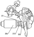
可选地,如图6、图7和图11所示,漏电锁扣27设于L极断路器模块1和N极断路器模块3之间,漏电锁扣27包括漏电锁扣本体272,其上端与漏电跳扣24搭接,下端能够推动N极锁扣331;具体地,漏电跳扣14的底部呈弧形,漏电锁扣本体272的顶部呈与漏电跳扣14相适配的弧形;具体地,漏电锁扣27还包括连接于漏电锁扣本体272下端的伸出部271,伸出部271与漏电锁扣本体呈夹角设置,伸出部271设于漏电锁扣本体朝向N极断路器模块3的一侧,伸出部271能够推动N极锁扣331,伸出部271能够伸入N极断路器模块内,以推动N极锁扣331,以进一步提高分断能力。Optionally, as shown in Figures 6, 7 and 11, the leakage lock 27 is provided between the L-pole circuit breaker module 1 and the N-pole circuit breaker module 3. The leakage lock 27 includes a leakage lock body 272, which The upper end overlaps with the leakage jumper 24, and the lower end can push the N-pole lock 331; specifically, the bottom of the leakage jumper 14 is arc-shaped, and the top of the leakage lock body 272 is in an arc shape that matches the leakage jumper 14. Specifically, the leakage lock 27 also includes an extension portion 271 connected to the lower end of the leakage lock body 272. The extension portion 271 is arranged at an angle with the leakage lock body. The extension 271 is located on the leakage lock body toward N. On one side of the pole circuit breaker module 3, the extension part 271 can push the N pole lock 331, and the extension part 271 can extend into the N pole circuit breaker module to push the N pole lock 331 to further improve the breaking capacity.
本实施例中,伸出部271垂直于漏电锁扣。优选地,伸出部271垂直于漏电锁扣本体272。In this embodiment, the extending portion 271 is perpendicular to the leakage lock. Preferably, the protruding portion 271 is perpendicular to the leakage lock body 272 .
如图12所示,摇臂26设于漏电锁扣本体272背离伸出部271的一侧,以便于伸出部271能够抵靠在N极锁扣331上,使结构更紧凑。As shown in FIG. 12 , the rocker arm 26 is provided on the side of the leakage lock body 272 away from the extension portion 271 so that the extension portion 271 can abut against the N-pole lock 331 to make the structure more compact.
如图10-图15所示,本实施例中,摇臂26包括摇臂本体261和设于摇臂本体261上的第一连接轴262,漏电锁扣27连接于第一连接轴262,且漏电锁扣27能够绕第一连接轴262旋转。具体地,脱扣器201推动漏电锁扣27时,漏电锁扣27绕第一连接轴262旋转,从而使漏电跳扣24和漏电锁扣27分离。具体地,摇臂本体261和第一连接轴262可以是一体结构也可以是分体结构。本实施例中,漏电锁扣本体272通过连接孔2721连接在第一连接轴262上。As shown in Figures 10-15, in this embodiment, the rocker arm 26 includes a rocker arm body 261 and a first connecting shaft 262 provided on the rocker arm body 261. The leakage lock 27 is connected to the first connecting shaft 262, and The leakage lock 27 can rotate around the first connecting axis 262 . Specifically, when the tripper 201 pushes the leakage lock 27, the leakage lock 27 rotates around the first connecting shaft 262, thereby separating the leakage jumper 24 and the leakage lock 27. Specifically, the rocker arm body 261 and the first connecting shaft 262 may be of an integrated structure or a separate structure. In this embodiment, the leakage lock body 272 is connected to the first connecting shaft 262 through the connecting hole 2721.
本实施例中,摇臂26还包括设于摇臂本体261上的安装孔264,摇臂本体261通过安装孔264连接于外壳的固定轴上,复位件25能够驱动摇臂本体261绕固定轴旋转。具体地,当复位件25驱动摇臂26旋转时,摇臂本体261绕固定轴旋转,漏电锁扣27与摇臂本体261同时旋转。In this embodiment, the rocker arm 26 also includes a mounting hole 264 provided on the rocker arm body 261. The rocker arm body 261 is connected to the fixed axis of the housing through the mounting hole 264. The reset member 25 can drive the rocker arm body 261 around the fixed axis. Rotate. Specifically, when the reset member 25 drives the rocker arm 26 to rotate, the rocker arm body 261 rotates around the fixed axis, and the leakage lock 27 and the rocker arm body 261 rotate simultaneously.
可选地,漏电脱扣极模块2还包括脱扣极手柄22和杠杆23,杠杆23连接脱扣极手柄22和漏电跳扣24,具体连接关系和工作原理等均可参照现有技术,不再赘述。Optionally, the leakage trip pole module 2 also includes a trip pole handle 22 and a lever 23. The lever 23 is connected to the trip pole handle 22 and the leakage jumper 24. The specific connection relationship and working principle can refer to the existing technology. Again.
本实施例中,摇臂26还包括设于摇臂本体261上的第二连接轴263,漏电跳扣24连接于第二连接轴263上,且漏电跳扣24能够绕第二连接轴263旋转;具体地,脱扣器201推动漏电锁扣27使漏电锁扣27绕第一连接轴262旋转时,漏电跳扣24与漏电锁扣27搭扣处解锁,一方面,由于之前合闸时手柄通过杠杆23连接漏电跳扣24使漏电跳扣24储能,当搭扣面分离时,漏电跳扣24能量释放进行旋转;另一方面,合闸时漏电跳扣24与摇臂26相接触,摇臂26与复位件25相抵接,复位件25储能,同时漏电跳扣24也储能,当搭扣面分离时,漏电跳扣24能量释放进行旋转,通过以上两个部分共同作用使漏电跳扣24绕第二连接轴263旋转,从而使漏电跳扣24和漏电锁扣27分离。In this embodiment, the rocker arm 26 also includes a second connection shaft 263 provided on the rocker arm body 261 , the leakage jumper 24 is connected to the second connection shaft 263 , and the leakage jumper 24 can rotate around the second connection shaft 263 ; Specifically, when the tripper 201 pushes the leakage lock 27 to rotate the leakage lock 27 around the first connecting shaft 262, the hasp of the leakage jumper 24 and the leakage lock 27 is unlocked. On the one hand, due to the previous closing of the handle, The leakage jumper 24 is connected through the lever 23 to store energy in the leakage jumper 24. When the buckle surface is separated, the energy of the leakage jumper 24 is released and rotates; on the other hand, when the switch is closed, the leakage jumper 24 is in contact with the rocker arm 26. The rocker arm 26 is in contact with the reset part 25. The reset part 25 stores energy, and the leakage jumper 24 also stores energy. When the buckle surface is separated, the leakage jumper 24 releases energy and rotates. The above two parts work together to cause leakage. The jump buckle 24 rotates around the second connecting axis 263, thereby separating the leakage jump buckle 24 and the leakage lock buckle 27.
进一步地,如图8和图9所示,摇臂26还包括连接于摇臂本体261一端的弯折结构265,拼装轴28能够位于弯折结构265内,增加弯折结构265与拼装轴28的接触面积,提高推动拼装轴28的可靠性。Further, as shown in Figures 8 and 9, the rocker arm 26 also includes a bending structure 265 connected to one end of the rocker arm body 261. The assembly shaft 28 can be located in the bending structure 265. The bending structure 265 and the assembly shaft 28 are added. The contact area improves the reliability of pushing the assembled shaft 28.
具体地,如图9和图10所示,第二连接轴263位于摇臂本体261的上部,复位件25抵接于摇臂本体261的上部。弯折结构265位于摇臂本体261的下部,安装孔264和第一连接轴262位于摇臂本体261的中部。复位件25作用于摇臂本体261的一端,摇臂本体261绕固定轴转动时,增强位于摇臂本体261另一端的弯折结构265对拼装轴28的作用力。具体地,复位件25为扭簧,扭簧固定于壳体上。Specifically, as shown in FIGS. 9 and 10 , the second connecting shaft 263 is located at the upper part of the rocker arm body 261 , and the return member 25 is in contact with the upper part of the rocker arm body 261 . The bending structure 265 is located at the lower part of the rocker arm body 261 , and the mounting hole 264 and the first connecting shaft 262 are located in the middle of the rocker arm body 261 . The reset member 25 acts on one end of the rocker arm body 261. When the rocker arm body 261 rotates around the fixed axis, the force exerted by the bending structure 265 at the other end of the rocker arm body 261 on the assembly shaft 28 is enhanced. Specifically, the return member 25 is a torsion spring, and the torsion spring is fixed on the housing.
如图1所示,一般地,L极断路器模块1设置在漏电脱扣极模块2的左侧,N极断路器模块3设置在漏电脱扣极模块2的右侧。As shown in Figure 1, generally, the L-pole circuit breaker module 1 is arranged on the left side of the earth leakage trip pole module 2, and the N-pole circuit breaker module 3 is arranged on the right side of the earth leakage trip pole module 2.
如图2所示,可选地,L极断路器模块1还包括L极瞬时动作线圈14,L极瞬时动作线圈14能够推动L极锁扣121跳闸。主回路产生短路电流时,通过L极瞬时动作线圈14的顶杆带动L极动触头机构12的L极锁扣跳闸,L极动触头机构12在运动的同时通过拼装轴28带动N极动触头机构33的N极锁扣331跳闸。可选地,L极断路器模块1包括双金属元件11,一般地,双金属元件11作为过载后备保护,一般情况下是电子式过载保护先动作,当电子保护失效后双金属元件11再动作,双金属元件11具体连接关系和工作原理等均可参照现有技术,不再赘述;进一步地,L极断路器模块1包括L极手柄13和L极灭弧室15,具体连接关系和工作原理等均可参照现有技术,不再赘述。As shown in Figure 2, optionally, the L-pole circuit breaker module 1 also includes an L-pole instantaneous action coil 14, and the L-pole instantaneous action coil 14 can push the L-pole latch 121 to trip. When a short-circuit current occurs in the main circuit, the push rod of the L-pole instantaneous action coil 14 drives the L-pole lock of the L-pole movable contact mechanism 12 to trip. The L-pole movable contact mechanism 12 drives the N pole through the assembly shaft 28 while moving. The N-pole lock 331 of the moving contact mechanism 33 trips. Optionally, the L-pole circuit breaker module 1 includes a bimetallic component 11. Generally, the bimetallic component 11 is used as an overload backup protection. Generally, the electronic overload protection operates first, and when the electronic protection fails, the bimetallic component 11 acts again. , the specific connection relationship and working principle of the bimetal component 11 can be referred to the existing technology, and will not be described in detail; further, the L pole circuit breaker module 1 includes an L pole handle 13 and an L pole arc extinguishing chamber 15. The specific connection relationship and working principle are The principles, etc. can be referred to the existing technology and will not be described again.
可选地,漏电脱扣极模块2还包括线路板29,脱扣器201与线路板29电连接,线路板29能够检测电流信号,当电流信号达到动作电流阀值时,脱扣器201推动漏电锁扣27。Optionally, the leakage trip pole module 2 also includes a circuit board 29. The release 201 is electrically connected to the circuit board 29. The circuit board 29 can detect the current signal. When the current signal reaches the action current threshold, the release 201 pushes Leakage lock 27.
可选地,如图2所示,漏电脱扣极模块2包括零序互感器20,零序互感器20和线路板29电连接。当回路中出现漏电流时,通过零序互感器20检测到回路中的漏电流,并通过线路板29分析判断,当漏电流达到动作阀值时驱动脱扣器201动作,之后再跳闸。Optionally, as shown in Figure 2, the leakage trip pole module 2 includes a zero sequence transformer 20, and the zero sequence transformer 20 is electrically connected to the circuit board 29. When leakage current occurs in the loop, the leakage current in the loop is detected by the zero sequence transformer 20 and analyzed and judged by the circuit board 29. When the leakage current reaches the action threshold, the tripper 201 is driven to act and then trips.
如图5所示,可选地,N极断路器模块3还包括电流互感器34,电流互感器34和线路板29电连接。电流互感器34检测到用电回路过电流,电流互感器34和线路板29电连接,通过线路板29分析判断,线路板29与脱扣器201电连接,当达到动作电流阀值时,驱动脱扣器201顶杆动作并带动L极断路器模块1和N极断路器模块3跳闸。As shown in Figure 5, optionally, the N-pole circuit breaker module 3 also includes a current transformer 34, and the current transformer 34 is electrically connected to the circuit board 29. The current transformer 34 detects the overcurrent of the power circuit, and the current transformer 34 is electrically connected to the circuit board 29. Through the analysis and judgment of the circuit board 29, the circuit board 29 is electrically connected to the tripper 201. When the operating current threshold is reached, the driver The release 201 push rod moves and drives the L-pole circuit breaker module 1 and N-pole circuit breaker module 3 to trip.
可选地,如图5所示,N极断路器模块3设有N极灭弧室30,提高了N极断路器模块3的分断能力。Optionally, as shown in Figure 5, the N-pole circuit breaker module 3 is provided with an N-pole arc extinguishing chamber 30, which improves the breaking capacity of the N-pole circuit breaker module 3.
可选地,如图5所示,N极断路器模块3包括N极手柄32,具体连接关系和工作原理等均可参照现有技术,不再赘述。Optionally, as shown in FIG. 5 , the N-pole circuit breaker module 3 includes an N-pole handle 32. The specific connection relationship and working principle may refer to the existing technology and will not be described again.
具体地,当漏电断路器出现短路保护及双金属元件11过载保护时,L极手柄13、N极手柄32均跳闸,脱扣极手柄22不跳闸;当出现漏电保护及电子式过载保护跳闸时,L极手柄13、N极手柄32、脱扣极手柄22均出现跳闸状态。Specifically, when the leakage circuit breaker has short-circuit protection and bimetallic element 11 overload protection, the L pole handle 13 and N pole handle 32 both trip, but the tripping pole handle 22 does not trip; when leakage protection and electronic overload protection trip , L-pole handle 13, N-pole handle 32, and tripping pole handle 22 are all tripped.
实施例二 Embodiment 2
本实施例提供一种剩余电流动作断路器,其与实施例一的结构基本相同,相同部分不再赘述。本实施例与实施例一的区别在于,拼装轴28与L极锁扣121间隙配合,与N极锁扣331固定连接。即N极锁扣331上不设置第一限位件3311,带孔的第二限位件(图中未示出)设置L极锁扣121上,拼装轴28的一端位于第二限位件的孔中,不固定连接。当漏电锁扣27、摇臂26推动拼装轴时,动作顺序为,拼装轴28首先带动N极锁扣331,之后再带动L极锁扣121运动,从而实现拼装轴28与L极动触头机构12和N极动触头机构33联动。This embodiment provides a residual current operated circuit breaker, which has a structure that is basically the same as that of Embodiment 1, and the same parts will not be described again. The difference between this embodiment and the first embodiment is that the assembly shaft 28 has a clearance fit with the L-pole lock 121 and is fixedly connected with the N-pole lock 331 . That is, the N-pole lock 331 is not provided with the first limiter 3311, and the second limiter (not shown in the figure) with a hole is provided on the L-pole lock 121, and one end of the assembly shaft 28 is located at the second limiter. holes, no fixed connection. When the leakage lock 27 and the rocker arm 26 push the assembly shaft, the sequence of actions is that the assembly shaft 28 first drives the N pole lock 331, and then drives the L pole lock 121 to move, thereby realizing the moving contact between the assembly shaft 28 and the L pole. The mechanism 12 is linked with the N pole moving contact mechanism 33.
进一步地,脱扣器201推动漏电锁扣27时,漏电锁扣27推动L极锁扣121,之后拼装轴28再推动L极锁扣121运动,通过在拼装轴28带动L极锁扣121运动之前,漏电锁扣27提前给L极锁扣121一个力,使拼装轴28更快地带动L极锁扣121运动,提高了同步性,进一步提高了分断能力。Further, when the tripper 201 pushes the leakage lock 27, the leakage lock 27 pushes the L-pole lock 121, and then the assembly shaft 28 pushes the L-pole lock 121 to move, and the assembly shaft 28 drives the L-pole lock 121 to move. Previously, the leakage lock 27 gave a force to the L pole lock 121 in advance, so that the assembly shaft 28 drove the L pole lock 121 to move faster, improving synchronization and further improving the breaking capacity.
本实施例中,由于第二限位件与拼装轴28的间隙配合而导致拼装轴28推动L极锁扣121时有力的传递损失,L极锁扣121动作较慢,或者L极锁扣121与拼装轴28之间间隙配合的行程较长等原因,虽然漏电锁扣27首先推动L极锁扣121,也不会导致L极锁扣121在漏电锁扣27和摇臂26之前抵接拼装轴28。即使L极锁扣121在漏电锁扣27和摇臂26之前抵接拼装轴28,也不具有足够的力推动拼装轴28,从而使漏电锁扣27和/或摇臂26能够推动拼装轴28此时,漏电锁扣27和摇臂26推动拼装轴28时的动作顺序与实施例一种的四种情况一致。In this embodiment, due to the clearance fit between the second limiting member and the assembly shaft 28 , the assembly shaft 28 causes a loss of power transmission when pushing the L-pole lock 121 , and the L-pole lock 121 moves slowly, or the L-pole lock 121 Due to reasons such as the long stroke of the clearance fit between the assembly shaft 28 and other reasons, although the leakage lock 27 pushes the L pole lock 121 first, it will not cause the L pole lock 121 to contact the assembly before the leakage lock 27 and the rocker arm 26 Axis 28. Even if the L-pole lock 121 abuts the assembly shaft 28 before the leakage lock 27 and the rocker arm 26 , it does not have enough force to push the assembly shaft 28 , so that the leakage lock 27 and/or the rocker arm 26 can push the assembly shaft 28 At this time, the action sequence of the leakage lock 27 and the rocker arm 26 when pushing the assembly shaft 28 is consistent with the four situations in the first embodiment.
具体地,漏电锁扣27包括漏电锁扣本体272和连接于漏电锁扣本体272的伸出部271,伸出部271与漏电锁扣本体272呈夹角设置,伸出部271设于漏电锁扣本体272朝向L极断路器模块1的一侧,伸出部271能够推动L极锁扣121,以进一步提高分断能力。Specifically, the leakage lock 27 includes a leakage lock body 272 and an extension part 271 connected to the leakage lock body 272. The extension part 271 is arranged at an angle with the leakage lock body 272, and the extension part 271 is provided on the leakage lock. The buckle body 272 faces the side of the L-pole circuit breaker module 1, and the extending portion 271 can push the L-pole lock buckle 121 to further improve the breaking capacity.
实施例三 Embodiment 3
本实施例提供一种剩余电流动作断路器,其与实施例一的结构基本相同,相同部分不再赘述。本实施例与实施例一的区别在于,拼装轴28与L极锁扣121固定连接,与N极锁扣331固定连接,该拼装轴28可以同时带动L极锁扣121与N极锁扣331,拼装轴28分别直接推动L极锁扣121和N极锁扣331时,大大减小了力的传递损失。当漏电锁扣27和/或摇臂26推动拼装轴28,漏电锁扣27不推动L极锁扣121或N极锁扣331,此时,四种情况与第一实施例一致。This embodiment provides a residual current operated circuit breaker, which has a structure that is basically the same as that of Embodiment 1, and the same parts will not be described again. The difference between this embodiment and the first embodiment is that the assembly shaft 28 is fixedly connected to the L-pole lock 121 and the N-pole lock 331. The assembly shaft 28 can drive the L-pole lock 121 and the N-pole lock 331 at the same time. , when the assembly shaft 28 directly pushes the L pole lock 121 and the N pole lock 331 respectively, the force transmission loss is greatly reduced. When the leakage lock 27 and/or the rocker arm 26 push the assembly shaft 28, the leakage lock 27 does not push the L-pole lock 121 or the N-pole lock 331. At this time, the four situations are consistent with the first embodiment.
此外,由于该实施例中,拼装轴28可以同时带动L极锁扣121与N极锁扣331运动,同步性高。因此,漏电锁扣27上无需设置伸出部271推动N极锁扣331或L极锁扣121。In addition, since in this embodiment, the assembly shaft 28 can drive the L-pole lock 121 and the N-pole lock 331 to move at the same time, the synchronization is high. Therefore, there is no need to provide an extension portion 271 on the leakage latch 27 to push the N-pole latch 331 or the L-pole latch 121 .
实施例四Embodiment 4
本实施例提供一种剩余电流动作断路器,其与实施例一、实施例二及实施例三的结构基本相同,相同部分不再赘述。本实施例与实施例一、实施例二及实施例三的区别在于,如图16所示,线路板29上电连接有状态指示模块,状态指示模块具有多种状态且能够择一地呈现其中一种状态,状态指示模块能够根据不同的电流呈现不同的状态,以便于识别。This embodiment provides a residual current operated circuit breaker, which has basically the same structure as Embodiment 1, Embodiment 2 and Embodiment 3, and the same parts will not be described again. The difference between this embodiment and Embodiment 1, Embodiment 2 and Embodiment 3 is that, as shown in Figure 16, the circuit board 29 is powered on and connected to a status indication module. The status indication module has multiple states and can selectively display one of them. A state, the status indication module can present different states according to different currents for easy identification.
可选地,状态指示模块包括指示灯292,还包括试验按钮21,试验按钮21包括按钮本体 211和连接端212,按钮本体211为透明结构,连接端212连接于线路板29,按钮本体211罩设于指示灯292,通过指示灯292显示断路器的故障状态,并透过按钮本体211直观的显示给用户查看。Optionally, the status indication module includes an indicator light 292 and a test button 21. The test button 21 includes a button body 211 and a connecting end 212. The button body 211 is a transparent structure. The connecting end 212 is connected to the circuit board 29. The button body 211 is covered. It is provided on the indicator light 292, and the fault status of the circuit breaker is displayed through the indicator light 292, and is intuitively displayed to the user through the button body 211.
可选地,指示灯292的状态为多种颜色中的一种、或多个闪烁频率中的一种、或多个颜色中的一种与多个闪烁频率中的一种的组合。Optionally, the state of the indicator light 292 is one of multiple colors, one of multiple flashing frequencies, or a combination of one of multiple colors and one of multiple flashing frequencies.
具体地,可采用蓝色和闪烁频率的组合形式进行指示,在线路板29上设置指示灯292用于区分两种保护状态,比如正常工作时试验按钮21显示蓝色,当出现漏电保护时,试验按钮21继续显示蓝色,脱扣极手柄22呈现跳闸状态,当出现电子式过载保护时,试验按钮21显示蓝色闪烁,脱扣极手柄22不出现跳闸状态,能够进一步区分电子式过载保护与漏电保护。当然也可以通过试验按钮21其它的状态,比如显示不同的颜色,或者显示闪烁不同的频率,显示两种不同的状态。Specifically, a combination of blue and flashing frequency can be used for indication. An indicator light 292 is provided on the circuit board 29 to distinguish two protection states. For example, the test button 21 displays blue during normal operation. When leakage protection occurs, The test button 21 continues to display blue, and the tripping pole handle 22 is in a tripped state. When electronic overload protection occurs, the test button 21 flashes blue, and the tripping pole handle 22 does not appear in a tripped state, which can further distinguish the electronic overload protection. with leakage protection. Of course, you can also test other states of the button 21, such as displaying different colors, or displaying different flashing frequencies, to display two different states.
进一步地,当剩余电流动作断路器具有更多功能时,如短路保护、电子式过载保护、作为后备保护的双金属元件11过载保护、漏电保护,过、欠压保护电流检测等时,线路板29上设有插孔291,插孔291可以作为电流校准孔设置在进、出线端,或者插孔291也可以作为通讯口,短路故障、过载故障、漏电故障状态通过剩余电流动作断路器外观上的试验按钮21直观显示。指示灯292的状态指示、L极手柄13、脱扣极手柄22及N极手柄32的动作状态与相应的故障关系对应如下:Further, when the residual current-operated circuit breaker has more functions, such as short-circuit protection, electronic overload protection, bimetallic element 11 overload protection as backup protection, leakage protection, over- and under-voltage protection current detection, etc., the circuit board 29 is provided with a jack 291. The jack 291 can be used as a current calibration hole set at the incoming and outgoing ends, or the jack 291 can also be used as a communication port. Short-circuit faults, overload faults, and leakage fault conditions are activated by the residual current. The test button 21 is visually displayed. The status indication of the indicator light 292, the action status of the L pole handle 13, the trip pole handle 22 and the N pole handle 32 correspond to the corresponding fault relationships as follows:
断路器正常工作时显示蓝色;指示短路故障,L极手柄13与N极手柄32跳闸、脱扣极手柄22不跳闸;指示过载故障,L极手柄13与N极手柄32跳闸、脱扣极手柄22跳闸、指示灯292显示红色;指示漏电故障,L极手柄13与N极手柄32跳闸、脱扣极手柄22跳闸、指示灯292显示蓝色;用电回路过压故障,L极手柄13与N极手柄32跳闸、脱扣极手柄22跳闸、指示灯292显示黄色;用电回路欠压故障,L极手柄13与N极手柄32跳闸、脱扣极手柄22跳闸、指示灯292显示黄色闪烁。When the circuit breaker is working normally, it displays blue; it indicates a short-circuit fault, the L pole handle 13 and the N pole handle 32 trip, and the tripping pole handle 22 does not trip; it indicates an overload fault, the L pole handle 13 and the N pole handle 32 trip, and the tripping pole Handle 22 tripped, indicator light 292 showed red; indicating leakage fault, L pole handle 13 and N pole handle 32 tripped, tripping pole handle 22 tripped, indicator light 292 showed blue; electrical circuit overvoltage fault, L pole handle 13 The N-pole handle 32 trips, the tripping pole handle 22 trips, and the indicator light 292 displays yellow; the power circuit is under-voltage, the L-pole handle 13 and the N-pole handle 32 trip, the tripping pole handle 22 trips, and the indicator light 292 displays yellow Flashing.
当然指示灯292颜色不限于上述几种,也可以通过改变指示灯292的闪烁频率指示状态等,不再赘述。Of course, the color of the indicator light 292 is not limited to the above-mentioned ones, and the status can also be indicated by changing the flashing frequency of the indicator light 292, which will not be described again.
显然,本发明的上述实施例仅仅是为了清楚说明本发明所作的举例,而并非是对本发明的实施方式的限定。对于所属领域的普通技术人员来说,在上述说明的基础上还可以做出其它不同形式的变化或变动。这里无需也无法对所有的实施方式予以穷举。凡在本发明的精神和原则之内所作的任何修改、等同替换和改进等,均应包含在本发明权利要求的保护范围之内。Obviously, the above-mentioned embodiments of the present invention are only examples for clearly illustrating the present invention, and are not intended to limit the implementation of the present invention. For those of ordinary skill in the art, other different forms of changes or modifications can be made based on the above description. An exhaustive list of all implementations is neither necessary nor possible. Any modifications, equivalent substitutions and improvements made within the spirit and principles of the present invention shall be included in the protection scope of the claims of the present invention.
Claims (15)
- 一种剩余电流动作断路器,包括L极断路器模块(1)、漏电脱扣极模块(2)和N极断路器模块(3),所述L极断路器模块(1)和所述N极断路器模块(3)分别设于所述漏电脱扣极模块(2)的两侧,所述L极断路器模块(1)包括L极动触头机构(12),所述N极断路器模块(3)包括N极动触头机构(33),其特征在于,所述漏电脱扣极模块(2)包括漏电跳扣(24)、漏电锁扣(27)、复位件(25)、摇臂(26)、拼装轴(28)和脱扣器(201),所述漏电跳扣(24)和所述漏电锁扣(27)能够相互搭接,所述摇臂(26)与所述复位件(25)抵接;A residual current-operated circuit breaker, including an L-pole circuit breaker module (1), a leakage trip pole module (2) and an N-pole circuit breaker module (3). The L-pole circuit breaker module (1) and the N-pole circuit breaker module (1) Pole circuit breaker modules (3) are respectively provided on both sides of the leakage trip pole module (2). The L-pole circuit breaker module (1) includes an L-pole movable contact mechanism (12), and the N-pole circuit breaker The device module (3) includes an N-pole movable contact mechanism (33), which is characterized in that the leakage trip pole module (2) includes a leakage jumper (24), a leakage lock (27), and a reset piece (25) , rocker arm (26), assembly shaft (28) and release (201), the leakage jumper (24) and the leakage lock (27) can overlap each other, the rocker arm (26) and the leakage lock (27) can overlap each other. The reset member (25) is in contact;所述拼装轴(28)与所述L极动触头机构(12)和所述N极动触头机构(33)联动;The assembly shaft (28) is linked with the L-pole movable contact mechanism (12) and the N-pole movable contact mechanism (33);所述摇臂(26)连接于所述漏电锁扣(27)的一侧,所述摇臂(26)和所述漏电锁扣(27)中的至少一个能够抵接于所述拼装轴(28);The rocker arm (26) is connected to one side of the leakage lock (27), and at least one of the rocker arm (26) and the leakage lock (27) can abut against the assembly shaft (27). 28);当用电回路中出现过载电流或漏电流时,所述脱扣器(201)能够推动所述漏电锁扣(27),使所述漏电跳扣(24)和所述漏电锁扣(27)分离时,所述漏电锁扣(27)沿靠近所述拼装轴(28)的方向旋转,且所述复位件(25)驱动所述摇臂(26)旋转,以使所述摇臂(26)和所述漏电锁扣(27)中的至少一个推动所述拼装轴(28)。When overload current or leakage current occurs in the power circuit, the tripper (201) can push the leakage lock (27), causing the leakage trip button (24) and the leakage lock (27) When separated, the leakage lock (27) rotates in a direction close to the assembly axis (28), and the reset member (25) drives the rocker arm (26) to rotate, so that the rocker arm (26 ) and at least one of the leakage lock (27) pushes the assembly shaft (28).
- 根据权利要求1所述的剩余电流动作断路器,其特征在于,The residual current operated circuit breaker according to claim 1, characterized in that:所述漏电锁扣(27)和所述摇臂(26)能够同时抵接拼装轴(28),以使所述摇臂(26)和所述漏电锁扣(27)同时推动所述拼装轴(28);或,The leakage lock (27) and the rocker arm (26) can abut the assembly shaft (28) at the same time, so that the rocker arm (26) and the leakage lock (27) push the assembly shaft at the same time (28); or,所述漏电锁扣(27)能够先于所述摇臂(26)抵接拼装轴(28),以使所述漏电锁扣(27)推动所述拼装轴(28);或,The leakage lock (27) can contact the assembly shaft (28) before the rocker arm (26), so that the leakage lock (27) pushes the assembly shaft (28); or,所述漏电锁扣(27)能够先于所述摇臂(26)抵接拼装轴(28),且所述摇臂(26)能够抵接拼装轴(28),以使所述摇臂(26)和所述漏电锁扣(27)同时推动所述拼装轴(28);或,The leakage lock (27) can contact the assembly shaft (28) before the rocker arm (26), and the rocker arm (26) can contact the assembly shaft (28), so that the rocker arm (26) can contact the assembly shaft (28). 26) and the leakage lock (27) push the assembly shaft (28) at the same time; or,所述摇臂(26)能够先于所述漏电锁扣(27)抵接拼装轴(28),以使所述摇臂(26)推动所述拼装轴(28)。The rocker arm (26) can contact the assembly shaft (28) before the leakage lock (27), so that the rocker arm (26) pushes the assembly shaft (28).
- 根据权利要求1所述的剩余电流动作断路器,其特征在于,所述L极动触头机构(12)包括L极锁扣(121),N极动触头机构(33)包括N极锁扣(331),The residual current-operated circuit breaker according to claim 1, characterized in that the L-pole movable contact mechanism (12) includes an L-pole lock (121), and the N-pole movable contact mechanism (33) includes an N-pole lock. buckle(331),所述拼装轴(28)与所述L极锁扣(121)固定连接,并与所述N极锁扣(331)间隙配合;或,The assembly shaft (28) is fixedly connected to the L-pole lock (121), and has a clearance fit with the N-pole lock (331); or,所述拼装轴(28)与所述L极锁扣(121)间隙配合,并与所述N极锁扣(331)固定连接;或,The assembly shaft (28) has a clearance fit with the L-pole lock (121) and is fixedly connected with the N-pole lock (331); or,所述拼装轴(28)与所述L极锁扣(121)固定连接,并与所述N极锁扣(331)固定连接。The assembly shaft (28) is fixedly connected to the L-pole lock (121) and fixedly connected to the N-pole lock (331).
- 根据权利要求3所述的剩余电流动作断路器,其特征在于,所述拼装轴(28)与所述L极锁扣(121)固定连接,并与所述N极锁扣(331)间隙配合,所述脱扣器(201)推动所述漏电锁扣(27)时,所述漏电锁扣(27)推动所述N极锁扣(331)。The residual current operated circuit breaker according to claim 3, characterized in that the assembly shaft (28) is fixedly connected to the L-pole lock (121) and has a clearance fit with the N-pole lock (331). , when the tripper (201) pushes the leakage lock (27), the leakage lock (27) pushes the N-pole lock (331).
- 根据权利要求4所述的剩余电流动作断路器,其特征在于,所述漏电锁扣(27)包括漏电锁扣本体(272)和连接于所述漏电锁扣本体(272)的伸出部(271),所述伸出部(271)与所述漏电锁扣本体(272)呈夹角设置,所述伸出部(271)设于所述漏电锁扣本体(272)朝向所述N极断路器模块(3)的一侧,所述伸出部(271)能够推动所述N极锁扣(331)。The residual current operated circuit breaker according to claim 4, characterized in that the leakage lock (27) includes a leakage lock body (272) and an extension portion (272) connected to the leakage lock body (272). 271), the extension portion (271) is arranged at an angle with the leakage lock body (272), and the extension portion (271) is located on the leakage lock body (272) toward the N pole. On one side of the circuit breaker module (3), the extension portion (271) can push the N-pole lock (331).
- 根据权利要求3所述的剩余电流动作断路器,其特征在于,所述拼装轴(28)与所述L极锁扣(121)间隙配合,并与所述N极锁扣(331)固定连接,所述脱扣器(201)推动所述漏电锁扣(27)时,所述漏电锁扣(27)推动所述L极锁扣(121)。The residual current operated circuit breaker according to claim 3, characterized in that the assembly shaft (28) has a clearance fit with the L-pole lock (121) and is fixedly connected with the N-pole lock (331). , when the tripper (201) pushes the leakage lock (27), the leakage lock (27) pushes the L-pole lock (121).
- 根据权利要求6所述的剩余电流动作断路器,其特征在于,所述漏电锁扣(27)包括漏电锁扣本体(272)和连接于所述漏电锁扣本体(272)的伸出部(271),所述伸出部(271)与所述漏电锁扣本体(272)呈夹角设置,所述伸出部(271)设于所述漏电锁扣本体(272)朝向所述L极断路器模块(1)的一侧,所述伸出部(271)能够推动所述L极锁 扣(121)。The residual current operated circuit breaker according to claim 6, wherein the leakage lock (27) includes a leakage lock body (272) and an extension portion (272) connected to the leakage lock body (272). 271), the extension portion (271) is arranged at an angle with the leakage lock body (272), and the extension portion (271) is located on the leakage lock body (272) toward the L pole On one side of the circuit breaker module (1), the extension portion (271) can push the L-pole lock (121).
- 根据权利要求5或7所述的剩余电流动作断路器,其特征在于,所述摇臂(26)设于所述漏电锁扣本体(272)背离所述伸出部(271)的一侧。The residual current-operated circuit breaker according to claim 5 or 7, characterized in that the rocker arm (26) is provided on a side of the leakage lock body (272) away from the extension portion (271).
- 根据权利要求1-7任一项所述的剩余电流动作断路器,其特征在于,所述摇臂(26)包括摇臂本体(261)和设于所述摇臂本体(261)上的第一连接轴(262),所述漏电锁扣(27)连接于所述第一连接轴(262),且所述漏电锁扣(27)能够绕所述第一连接轴(262)旋转。The residual current-operated circuit breaker according to any one of claims 1 to 7, characterized in that the rocker arm (26) includes a rocker arm body (261) and a third rocker arm body (261). A connecting shaft (262), the leakage lock (27) is connected to the first connecting shaft (262), and the leakage lock (27) can rotate around the first connecting shaft (262).
- 根据权利要求1-7任一项所述的剩余电流动作断路器,其特征在于,所述摇臂(26)包括摇臂本体(261)和设于所述摇臂本体(261)上的安装孔(264),所述摇臂本体(261)通过所述安装孔(264)连接于外壳的固定轴上,所述复位件(25)能够驱动所述摇臂本体(261)绕所述固定轴旋转。The residual current operated circuit breaker according to any one of claims 1 to 7, characterized in that the rocker arm (26) includes a rocker arm body (261) and a mounting plate provided on the rocker arm body (261). hole (264), the rocker arm body (261) is connected to the fixed shaft of the housing through the mounting hole (264), and the reset member (25) can drive the rocker arm body (261) around the fixed shaft. axis rotation.
- 根据权利要求1-7任一项所述的剩余电流动作断路器,其特征在于,所述摇臂(26)包括摇臂本体(261)和设于所述摇臂本体(261)上的第二连接轴(263),所述漏电跳扣(24)连接于所述第二连接轴(263)上,且所述漏电跳扣(24)能够绕所述第二连接轴(263)旋转。The residual current-operated circuit breaker according to any one of claims 1 to 7, characterized in that the rocker arm (26) includes a rocker arm body (261) and a third rocker arm body (261). Two connection shafts (263), the leakage jumper (24) is connected to the second connection shaft (263), and the leakage jumper (24) can rotate around the second connection shaft (263).
- 根据权利要求1-7任一项所述的剩余电流动作断路器,其特征在于,所述摇臂(26)包括摇臂本体(261)和连接于所述摇臂本体(261)一端的弯折结构(265),所述弯折结构(265)围绕所述拼装轴(28)设置。The residual current operated circuit breaker according to any one of claims 1 to 7, characterized in that the rocker arm (26) includes a rocker arm body (261) and an elbow connected to one end of the rocker arm body (261). A folding structure (265) is provided around the assembly axis (28).
- 根据权利要求1-7任一项所述的剩余电流动作断路器,其特征在于,所述漏电脱扣极模块(2)还包括线路板(29)和状态指示模块,所述脱扣器(201)和所述状态指示模块分别与所述线路板(29)电连接,所述线路板(29)能够检测电流信号,当所述电流信号达到动作电流阀值时,所述脱扣器(201)推动所述漏电锁扣(27),所述状态指示模块具有多种状态且能够呈现多种状态中的一种状态。The residual current-operated circuit breaker according to any one of claims 1 to 7, characterized in that the leakage trip pole module (2) also includes a circuit board (29) and a status indication module, and the tripper (2) 201) and the status indication module are electrically connected to the circuit board (29) respectively. The circuit board (29) can detect a current signal. When the current signal reaches the action current threshold, the tripper (201) 201) Push the leakage latch (27), the status indication module has multiple states and can present one of the multiple states.
- 根据权利要求13所述的剩余电流动作断路器,其特征在于,所述状态指示模块包括指示灯(292),所述漏电脱扣极模块(2)还包括试验按钮(21),所述试验按钮(21)包括按钮本体(211)和连接端(212),所述按钮本体(211)为透明结构,所述连接端(212)连接于所述线路板(29),所述按钮本体(211)罩设于所述指示灯(292)。The residual current operated circuit breaker according to claim 13, characterized in that the status indication module includes an indicator light (292), the leakage trip pole module (2) further includes a test button (21), and the test button The button (21) includes a button body (211) and a connecting end (212). The button body (211) is a transparent structure. The connecting end (212) is connected to the circuit board (29). The button body (212) is connected to the circuit board (29). 211) is covered with the indicator light (292).
- 根据权利要求1-7任一项所述的剩余电流动作断路器,其特征在于,所述漏电脱扣极模块(2)还包括零序互感器(20),所述N极断路器模块(3)还包括电流互感器(34)。The residual current-operated circuit breaker according to any one of claims 1 to 7, characterized in that the leakage trip pole module (2) also includes a zero sequence transformer (20), and the N-pole circuit breaker module (2) 3) Also includes a current transformer (34).
Priority Applications (2)
| Application Number | Priority Date | Filing Date | Title |
|---|---|---|---|
| AU2022453596A AU2022453596A1 (en) | 2022-06-08 | 2022-09-07 | Residual current operated circuit breaker |
| EP22937661.1A EP4318538A1 (en) | 2022-06-08 | 2022-09-07 | Residual current operated circuit breaker |
Applications Claiming Priority (2)
| Application Number | Priority Date | Filing Date | Title |
|---|---|---|---|
| CN202210643972.7A CN114899055A (en) | 2022-06-08 | 2022-06-08 | Residual current operated circuit breaker |
| CN202210643972.7 | 2022-06-08 |
Publications (1)
| Publication Number | Publication Date |
|---|---|
| WO2023236380A1 true WO2023236380A1 (en) | 2023-12-14 |
Family
ID=82727712
Family Applications (1)
| Application Number | Title | Priority Date | Filing Date |
|---|---|---|---|
| PCT/CN2022/117552 WO2023236380A1 (en) | 2022-06-08 | 2022-09-07 | Residual current operated circuit breaker |
Country Status (4)
| Country | Link |
|---|---|
| EP (1) | EP4318538A1 (en) |
| CN (1) | CN114899055A (en) |
| AU (1) | AU2022453596A1 (en) |
| WO (1) | WO2023236380A1 (en) |
Families Citing this family (1)
| Publication number | Priority date | Publication date | Assignee | Title |
|---|---|---|---|---|
| CN114899055A (en) * | 2022-06-08 | 2022-08-12 | 浙江正泰电器股份有限公司 | Residual current operated circuit breaker |
Citations (5)
| Publication number | Priority date | Publication date | Assignee | Title |
|---|---|---|---|---|
| CN102683131A (en) * | 2011-03-09 | 2012-09-19 | 上海电科电器科技有限公司 | Circuit breaker for optimizing space allocation |
| CN108511288A (en) * | 2018-03-07 | 2018-09-07 | 广东南冠电气有限公司 | A kind of compact electromagnetic dropout type leakage circuit breakers |
| CN212783272U (en) * | 2020-07-03 | 2021-03-23 | 浙江正泰电器股份有限公司 | Residual current operated circuit breaker |
| CN113889377A (en) * | 2020-07-02 | 2022-01-04 | 浙江正泰电器股份有限公司 | Circuit breaker |
| CN114899055A (en) * | 2022-06-08 | 2022-08-12 | 浙江正泰电器股份有限公司 | Residual current operated circuit breaker |
-
2022
- 2022-06-08 CN CN202210643972.7A patent/CN114899055A/en active Pending
- 2022-09-07 WO PCT/CN2022/117552 patent/WO2023236380A1/en active Application Filing
- 2022-09-07 AU AU2022453596A patent/AU2022453596A1/en active Pending
- 2022-09-07 EP EP22937661.1A patent/EP4318538A1/en active Pending
Patent Citations (5)
| Publication number | Priority date | Publication date | Assignee | Title |
|---|---|---|---|---|
| CN102683131A (en) * | 2011-03-09 | 2012-09-19 | 上海电科电器科技有限公司 | Circuit breaker for optimizing space allocation |
| CN108511288A (en) * | 2018-03-07 | 2018-09-07 | 广东南冠电气有限公司 | A kind of compact electromagnetic dropout type leakage circuit breakers |
| CN113889377A (en) * | 2020-07-02 | 2022-01-04 | 浙江正泰电器股份有限公司 | Circuit breaker |
| CN212783272U (en) * | 2020-07-03 | 2021-03-23 | 浙江正泰电器股份有限公司 | Residual current operated circuit breaker |
| CN114899055A (en) * | 2022-06-08 | 2022-08-12 | 浙江正泰电器股份有限公司 | Residual current operated circuit breaker |
Also Published As
| Publication number | Publication date |
|---|---|
| EP4318538A1 (en) | 2024-02-07 |
| AU2022453596A1 (en) | 2024-01-04 |
| CN114899055A (en) | 2022-08-12 |
Similar Documents
| Publication | Publication Date | Title |
|---|---|---|
| WO2013185421A1 (en) | Dual-mechanism 1p+n earth leakage circuit breaker | |
| EP3171386A1 (en) | Low-voltage circuit breaker with residual current tripping device | |
| WO2023236380A1 (en) | Residual current operated circuit breaker | |
| CA2783232C (en) | Electrical switching apparatus and secondary trip mechanism therefor | |
| CN212783318U (en) | Circuit breaker | |
| WO2012119555A1 (en) | Circuit breaker for optimizing space allocation | |
| CN213184171U (en) | Hydraulic electromagnetic circuit breaker with double arc extinguish chambers | |
| CN201256130Y (en) | Improved circuit breaker | |
| CN111477503A (en) | Plug-in circuit breaker | |
| CN217655831U (en) | Residual current operated circuit breaker | |
| CN102568948B (en) | Improved circuit breaker | |
| CN212695091U (en) | Compact reclosing circuit breaker | |
| CN110534379B (en) | 4P leakage circuit breaker with leakage indicating mechanism | |
| CN113078035A (en) | High-breaking miniature circuit breaker | |
| CN113889377A (en) | Circuit breaker | |
| CN216902743U (en) | Intelligent control unit of plug-in circuit breaker | |
| CN216902721U (en) | Intelligent circuit breaker | |
| CN218241746U (en) | Circuit breaker | |
| CN215869224U (en) | Circuit breaker | |
| CN212322933U (en) | Operating mechanism of miniature circuit breaker | |
| CN212783329U (en) | Residual current circuit breaker | |
| CN212783282U (en) | Compact reclosing circuit breaker | |
| CN214956668U (en) | Small-sized circuit breaker | |
| CN217239371U (en) | Switching-on and switching-off mechanism and miniature circuit breaker | |
| CN212783331U (en) | Compact reclosing circuit breaker |
Legal Events
| Date | Code | Title | Description |
|---|---|---|---|
| WWE | Wipo information: entry into national phase |
Ref document number: 2022453596 Country of ref document: AU |
|
| ENP | Entry into the national phase |
Ref document number: 2022937661 Country of ref document: EP Effective date: 20231024 |
|
| ENP | Entry into the national phase |
Ref document number: 2022453596 Country of ref document: AU Date of ref document: 20220907 Kind code of ref document: A |