WO2023233723A1 - Catheter - Google Patents
Catheter Download PDFInfo
- Publication number
- WO2023233723A1 WO2023233723A1 PCT/JP2023/005300 JP2023005300W WO2023233723A1 WO 2023233723 A1 WO2023233723 A1 WO 2023233723A1 JP 2023005300 W JP2023005300 W JP 2023005300W WO 2023233723 A1 WO2023233723 A1 WO 2023233723A1
- Authority
- WO
- WIPO (PCT)
- Prior art keywords
- reinforcing body
- shaft
- catheter
- overlapping
- reinforcing
- Prior art date
Links
- 230000003014 reinforcing effect Effects 0.000 claims description 184
- 238000004804 winding Methods 0.000 claims description 18
- 230000002787 reinforcement Effects 0.000 abstract description 43
- 239000003550 marker Substances 0.000 description 22
- 239000000463 material Substances 0.000 description 12
- 238000010586 diagram Methods 0.000 description 10
- 230000000052 comparative effect Effects 0.000 description 5
- 229920005989 resin Polymers 0.000 description 5
- 239000011347 resin Substances 0.000 description 5
- 206010002329 Aneurysm Diseases 0.000 description 4
- 230000003073 embolic effect Effects 0.000 description 4
- 210000004204 blood vessel Anatomy 0.000 description 3
- 238000005516 engineering process Methods 0.000 description 3
- 239000012530 fluid Substances 0.000 description 3
- -1 polytetrafluoroethylene Polymers 0.000 description 3
- 229910045601 alloy Inorganic materials 0.000 description 2
- 239000000956 alloy Substances 0.000 description 2
- 239000007769 metal material Substances 0.000 description 2
- 238000000034 method Methods 0.000 description 2
- 229910001000 nickel titanium Inorganic materials 0.000 description 2
- 230000002093 peripheral effect Effects 0.000 description 2
- 229920001343 polytetrafluoroethylene Polymers 0.000 description 2
- 239000004810 polytetrafluoroethylene Substances 0.000 description 2
- 230000005855 radiation Effects 0.000 description 2
- 230000000452 restraining effect Effects 0.000 description 2
- 239000000126 substance Substances 0.000 description 2
- WFKWXMTUELFFGS-UHFFFAOYSA-N tungsten Chemical compound [W] WFKWXMTUELFFGS-UHFFFAOYSA-N 0.000 description 2
- 229910052721 tungsten Inorganic materials 0.000 description 2
- 239000010937 tungsten Substances 0.000 description 2
- 208000005189 Embolism Diseases 0.000 description 1
- 239000004677 Nylon Substances 0.000 description 1
- 229930182556 Polyacetal Natural products 0.000 description 1
- 239000004952 Polyamide Substances 0.000 description 1
- 239000004695 Polyether sulfone Substances 0.000 description 1
- 239000004743 Polypropylene Substances 0.000 description 1
- 230000002785 anti-thrombosis Effects 0.000 description 1
- 239000003146 anticoagulant agent Substances 0.000 description 1
- 210000003445 biliary tract Anatomy 0.000 description 1
- 238000009954 braiding Methods 0.000 description 1
- 210000002249 digestive system Anatomy 0.000 description 1
- 230000000916 dilatatory effect Effects 0.000 description 1
- 230000000694 effects Effects 0.000 description 1
- 229920001971 elastomer Polymers 0.000 description 1
- 239000000806 elastomer Substances 0.000 description 1
- 210000004907 gland Anatomy 0.000 description 1
- 238000009940 knitting Methods 0.000 description 1
- 210000004324 lymphatic system Anatomy 0.000 description 1
- 238000004519 manufacturing process Methods 0.000 description 1
- 238000012986 modification Methods 0.000 description 1
- 230000004048 modification Effects 0.000 description 1
- 229920001778 nylon Polymers 0.000 description 1
- 210000000056 organ Anatomy 0.000 description 1
- 229920002647 polyamide Polymers 0.000 description 1
- 229920006122 polyamide resin Polymers 0.000 description 1
- 229920000515 polycarbonate Polymers 0.000 description 1
- 239000004417 polycarbonate Substances 0.000 description 1
- 229920001225 polyester resin Polymers 0.000 description 1
- 239000004645 polyester resin Substances 0.000 description 1
- 229920006393 polyether sulfone Polymers 0.000 description 1
- 229920005672 polyolefin resin Polymers 0.000 description 1
- 229920006324 polyoxymethylene Polymers 0.000 description 1
- 229920001155 polypropylene Polymers 0.000 description 1
- 229920005749 polyurethane resin Polymers 0.000 description 1
- 230000001850 reproductive effect Effects 0.000 description 1
- 210000002345 respiratory system Anatomy 0.000 description 1
- 230000003248 secreting effect Effects 0.000 description 1
- 229920002050 silicone resin Polymers 0.000 description 1
- 229910001256 stainless steel alloy Inorganic materials 0.000 description 1
- 210000001635 urinary tract Anatomy 0.000 description 1
- 230000002792 vascular Effects 0.000 description 1
Images

Classifications
-
- A—HUMAN NECESSITIES
- A61—MEDICAL OR VETERINARY SCIENCE; HYGIENE
- A61M—DEVICES FOR INTRODUCING MEDIA INTO, OR ONTO, THE BODY; DEVICES FOR TRANSDUCING BODY MEDIA OR FOR TAKING MEDIA FROM THE BODY; DEVICES FOR PRODUCING OR ENDING SLEEP OR STUPOR
- A61M25/00—Catheters; Hollow probes
Definitions
- the technology disclosed herein relates to a catheter.
- a catheter is a long medical device that is inserted into a living body lumen such as a blood vessel and used to diagnose or treat the inside of the living body lumen.
- the catheter includes a cylindrical shaft and a reinforcing body that reinforces the shaft.
- As the reinforcing body for example, a coil body spirally wound around the shaft is used (see, for example, Patent Document 1).
- the shaft may stretch.
- an object e.g., an embolic coil for plugging an aneurysm or a highly viscous embolus.
- the resistance between the object and the surface of the lumen may cause the shaft to elongate.
- the catheter when the catheter is inserted into a bent part or an occluded part in a blood vessel and then pulled back toward the proximal end, the shaft may be stretched.
- a simple coil body is used as a reinforcement body to reinforce the shaft, so when the shaft tries to stretch, the reinforcement body stretches or misaligns, and the reinforcement body There is a problem in that it is not possible to sufficiently improve the elongation resistance of.
- This specification discloses a technique that can solve the above-mentioned problems.
- the catheter disclosed herein includes a cylindrical shaft, a first reinforcing body, and a second reinforcing body.
- the first reinforcing body is composed of a plurality of wires wound helically around the shaft.
- the second reinforcing body is composed of at least one strand of wire spirally wound around the shaft so as to overlap the first reinforcing body in the radial direction of the shaft.
- the first reinforcing body is located radially inward of the shaft from the second reinforcing body. do.
- the first reinforcing body is located radially outward of the shaft from the second reinforcing body.
- the first reinforcing body and the second reinforcing body restrain each other. Therefore, according to this catheter, when the shaft tries to stretch, the first reinforcing body and the second reinforcing body restrain each other, thereby preventing stretching or positional shift, and the first reinforcing body
- the elongation resistance of the shaft can be sufficiently improved by the body and the second reinforcing body.
- At least some of the overlapping locations may be configured such that the first overlapping locations and the second overlapping locations are regularly arranged along the longitudinal direction of the shaft. If this configuration is adopted, the first reinforcing body and the second reinforcing body firmly restrain each other, so that the elongation resistance of the shaft can be further effectively improved.
- the overlapping locations may be configured such that the first overlapping locations and the second overlapping locations are alternately arranged along the longitudinal direction of the shaft. If this configuration is adopted, the first reinforcing body and the second reinforcing body restrain each other more firmly, so that the elongation resistance of the shaft can be extremely effectively improved.
- the number of strands constituting the second reinforcing body may be smaller than the number of strands constituting the first reinforcing body.
- the winding direction of the second reinforcing body and the winding direction of the first reinforcing body may be opposite to each other.
- the number of overlapping parts of the first reinforcement body and the second reinforcement body is increased. I can do it. Therefore, if this configuration is adopted, the first reinforcing body and the second reinforcing body restrain each other more firmly, thereby effectively improving the elongation resistance of the shaft.
- An explanatory diagram schematically showing the side configuration of the catheter 100 of this embodiment An explanatory diagram schematically showing a cross-sectional configuration of a portion of the catheter 100 (X1 section in FIG. 1) An explanatory diagram schematically showing a side configuration of a portion of the catheter 100 (X1 portion in FIG.
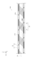
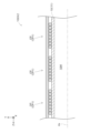
- FIG. 1 is an explanatory view schematically showing a side configuration of a catheter 100 of the present embodiment
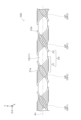
- FIG. 2 is an explanatory view schematically showing a cross-sectional configuration of a portion of the catheter 100 (X1 portion in FIG. 1).
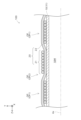
- FIG. 3 is an explanatory diagram schematically showing a side configuration of a portion of the catheter 100 (portion X1 in FIG. 1).
- each figure shows XYZ axes that are orthogonal to each other.
- the Z-axis positive direction side is the distal end side (distal side) inserted into the body
- the Z-axis negative direction side is the base end side (proximal side) operated by a technician such as a doctor.
- a part of the structure of the catheter 100 is shown enlarged or omitted as appropriate.
- each figure shows a state in which the central axis Ax of the catheter 100 is approximately straight parallel to the Z-axis direction, the catheter 100 has flexibility to the extent that it can be curved. .
- distal end is referred to as the "distal end”
- distal end and the vicinity thereof is referred to as the “distal end”
- proximal end is referred to as the "proximal end”
- proximal end is referred to as the proximal end
- the catheter 100 is inserted into a living body lumen such as a vascular system, a lymphatic system, a biliary system, a urinary tract system, a respiratory system, a digestive system, a secretory gland, and a reproductive organ, and is used to diagnose or treat the inside of a living body lumen.
- a living body lumen such as a vascular system, a lymphatic system, a biliary system, a urinary tract system, a respiratory system, a digestive system, a secretory gland, and a reproductive organ.
- the catheter 100 includes a shaft 10, a distal reinforcement 20, a proximal reinforcement 30, and a connector 90.
- the shaft 10 is a cylindrical long member that extends along the central axis Ax.
- the shaft 10 is formed with an inner cavity 10M (FIG. 2) that extends along the central axis Ax from the distal end to the proximal end of the shaft 10.
- the cross-sectional shape of the inner cavity 10M can take any arbitrary shape, but is approximately circular, for example.
- the lumen 10M of the shaft 10 is for passing a concomitant device (e.g., a guide wire, a microcatheter, etc.) or a fluid (e.g., an embolic material for occluding an aneurysm, an expansion medium for dilating a balloon catheter, etc.). used for.
- a concomitant device e.g., a guide wire, a microcatheter, etc.
- a fluid e.g., an embolic material for occluding an aneurysm, an expansion medium for dilating a
- the outer diameter, inner diameter, and overall length of the shaft 10 can be set arbitrarily.
- the outer diameter of the shaft 10 is, for example, about 0.2 mm to 2.0 mm, and the total length of the shaft 10 is, for example, about 1200 to 1800 mm.
- a first marker 18 and a second marker 19 are provided at the tip of the shaft 10.
- the first marker 18 is placed near the tip of the shaft 10, and the second marker 19 is placed a predetermined distance (for example, about 30 mm) from the first marker 18 on the proximal side.
- the first marker 18 and the second marker 19 are made of a radiopaque material.
- a technician such as a doctor can grasp the position of the tip of the shaft 10 by visually recognizing the first marker 18 under radiation. Further, even if the first marker 18 cannot be visually recognized under radiation, the operator can grasp the position of the tip of the shaft 10 based on the position where the second marker 19 is visually recognized and the predetermined distance.
- the shaft 10 is composed of an inner layer 11 and an outer layer 12.
- the inner layer 11 is a cylindrical member that defines the inner cavity 10M
- the outer layer 12 is a cylindrical member that covers the outer periphery of the inner layer 11. Note that in FIG. 3, illustration of the outer layer 12 is omitted for convenience of explanation.
- the shaft 10 is preferably formed of a material that is antithrombotic, flexible, and biocompatible.
- materials for forming the shaft 10 include resin materials such as polyamide resin, polyolefin resin, polyester resin, polyurethane resin, silicone resin, and fluororesin.
- the inner layer 11 is made of polytetrafluoroethylene (PTFE), and the outer layer 12 is made of nylon-based elastomer resin.
- the configuration including the material forming the shaft 10 may be uniform over the entire length, or may be different from section to section along the longitudinal direction.
- the connector 90 constitutes the proximal end of the catheter 100 and is a member held by the operator.
- the connector 90 includes, for example, a substantially cylindrical main body 91 and a plurality of blades 92 formed on the outer peripheral surface of the main body 91.
- a proximal end portion of the shaft 10 is inserted and joined to the distal end portion of the main body portion 91 .
- An opening (not shown) communicating with the inner cavity 10M of the shaft 10 is formed at the base end of the main body portion 91 .
- the connector 90 is made of a resin material such as polyamide, polypropylene, polycarbonate, polyacetal, polyether sulfone, or the like.
- the distal end reinforcement body 20 is a member for reinforcing the shaft 10 and is embedded in the distal end portion of the shaft 10. As shown in FIG. 2, the distal end reinforcement body 20 is wrapped around the outer peripheral surface of the inner layer 11 of the shaft 10 and covered by the outer layer 12 of the shaft 10. The configuration of the distal end reinforcement body 20 will be described in detail later.
- the proximal reinforcing body 30 is a member for reinforcing the shaft 10, and is buried in a portion of the shaft 10 closer to the proximal end than the portion where the distal reinforcing body 20 is buried.
- the proximal reinforcing body 30 may have any configuration, but for example, it may be a mesh-shaped cylindrical body (a so-called braid) made of wires in a mesh weave, or it may be a mesh-shaped cylindrical body made of wires wound in a spiral shape. It may be a coil body.
- the proximal reinforcing body 30 is made of, for example, a metal material or a resin material. In FIG. 1, for convenience of explanation, the distal end reinforcing body 20 and the proximal reinforcing body 30 embedded in the shaft 10 are shown by solid lines.
- the distal end reinforcing body 20 includes a first reinforcing body 21 and a second reinforcing body 22. As shown in FIGS. 2 and 3, the distal end reinforcing body 20 includes a first reinforcing body 21 and a second reinforcing body 22. As shown in FIGS. 2 and 3, the distal end reinforcing body 20 includes a first reinforcing body 21 and a second reinforcing body 22. As shown in FIGS.
- the first reinforcing body 21 is a coil body composed of a plurality of wires 21a spirally wound around the shaft 10.
- the first reinforcing body 21 is composed of eight strands 21a.
- the eight wires 21a constituting the first reinforcing body 21 are arranged so as to be in contact with each other along the longitudinal direction of the shaft 10 (direction parallel to the central axis Ax).
- the first reinforcing body 21 is configured by loosely winding an assembly of these eight wires 21a in a spiral shape.
- the first reinforcing body 21 is Z-wound around the shaft 10.
- the second reinforcing body 22 is a coil body composed of at least one strand 22a spirally wound around the shaft 10 so as to overlap with the first reinforcing body 21 in the radial direction of the shaft 10.
- the second reinforcing body 22 is composed of one strand 22a. That is, the number of strands 22a constituting the second reinforcing body 22 is smaller than the number of strands 21a constituting the first reinforcing body 21.
- the second reinforcing body 22 is configured by loosely winding this single wire 22a in a spiral shape.
- the second reinforcing body 22 is wound around the shaft 10 in an S-wound manner. That is, the winding direction of the second reinforcement body 22 and the winding direction of the first reinforcement body 21 are opposite.
- the first reinforcing body 21 and the second reinforcing body 22 are formed of, for example, a metal material (stainless steel alloy such as SUS304, NiTi alloy, tungsten, etc.) or a resin material. Note that since the number of strands 22a constituting the second reinforcing body 22 is smaller than the number of strands 21a constituting the first reinforcing body 21, the load is concentrated on the strands 22a constituting the second reinforcing body 22. It is preferable that the tensile strength of the material forming the second reinforcing body 22 is higher than the tensile strength of the material forming the first reinforcing body 21.
- the first reinforcing body 21 is made of, for example, a NiTi alloy
- the second reinforcing body 22 is made of, for example, tungsten.
- both the first reinforcing body 21 and the second reinforcing body 22 are spiral coil bodies, they overlap in the radial direction of the shaft 10 at a plurality of overlapping points OP.
- the first reinforcing body 21 is located on the radially inner side of the shaft 10 (hereinafter simply referred to as "inner side") than the second reinforcing body 22. ing.
- the first reinforcing body 21 is located on the radially outer side of the shaft 10 (hereinafter simply referred to as "outer side") than the second reinforcing body 22. ).
- the first reinforcing body 21 overlaps with the second reinforcing body 22 such that the first reinforcing body 21 overlaps with the second reinforcing body OP1, and the first reinforcing body 21 overlaps with the second reinforcing body 22 so that the first reinforcing body 21 A second overlapping location OP2 where the two overlap so as to be located outside the body 22 coexists.
- a first overlapping point OP1 and a second overlapping point are arranged along the longitudinal direction of the shaft 10 (direction parallel to the central axis Ax).
- OP2 are arranged alternately.
- the first overlapping points OP1 and the second overlapping points OP2 are regularly arranged along the longitudinal direction of the shaft 10.
- first overlapping points OP1 and second overlapping points OP2 are arranged alternately along the longitudinal direction of the shaft 10.
- first reinforcing body 21 and the second reinforcing body 22 having such a configuration are formed by, for example, using a braiding machine to form bobbins for the eight strands 21a for the first reinforcing body 21 and the second reinforcing body 21. It can be produced by knitting each strand while relatively moving the bobbin for one strand 22a for the body 22.
- the catheter 100 of this embodiment includes the cylindrical shaft 10, the first reinforcing body 21, and the second reinforcing body 22.
- the first reinforcing body 21 is composed of a plurality of wires 21a spirally wound around the shaft 10.
- the second reinforcing body 22 is composed of at least one strand 22a spirally wound around the shaft 10 so as to overlap with the first reinforcing body 21 in the radial direction of the shaft 10.
- the first overlapping point OP1 which is a part of the plurality of overlapping points OP between the first reinforcing body 21 and the second reinforcing body 22
- the first reinforcing body 21 is located on the radially inner side of the shaft 10 than the second reinforcing body 22.
- the second overlapping point OP2 which is another part of the plurality of overlapping points OP, the first reinforcing body 21 is located radially outward of the shaft 10 from the second reinforcing body 22.
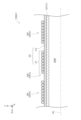
- FIG. 4 is an explanatory diagram schematically showing the configuration of the first reinforcing body 21 and the second reinforcing body 22 in the catheter 100 of this embodiment.
- FIG. 5 is an explanatory diagram schematically showing the configuration of the first reinforcing body 21 and the second reinforcing body 22 in the catheter 100X1 of the first comparative example
- FIG. FIG. 2 is an explanatory diagram schematically showing the configurations of a first reinforcing body 21 and a second reinforcing body 22.
- the first reinforcing body 21 is not restrained by the second reinforcing body 22.
- the second reinforcing body 22 is restrained by the tension of the first reinforcing body 21, the restraining force is small. Therefore, when the shaft 10 tries to stretch, the first reinforcing body 21 and the second reinforcing body 22 stretch or become misaligned, and the first reinforcing body 21 and the second reinforcing body 22 cause the shaft 10 to It is not possible to sufficiently improve elongation resistance.
- the second reinforcement body 22 is not restrained by the first reinforcement body 21.
- the first reinforcing body 21 is restrained by the tension of the second reinforcing body 22, the restraining force is small. Therefore, when the shaft 10 tries to stretch, the first reinforcing body 21 and the second reinforcing body 22 stretch or become misaligned, and the first reinforcing body 21 and the second reinforcing body 22 cause the shaft 10 to It is not possible to sufficiently improve elongation resistance.
- the first reinforcing body 21 overlaps the first overlapping portion OP1 located inside the second reinforcing body 22, and the first reinforcing body 21 overlaps the second reinforcing body 22.
- a second overlapping portion OP2 located outside the reinforcing body 22 is also present. Therefore, the first reinforcing body 21 and the second reinforcing body 22 restrain each other. Therefore, when the shaft 10 tries to stretch, the first reinforcing body 21 and the second reinforcing body 22 are restrained from stretching or misaligning due to mutual restraint, and the first reinforcing body 21 and the second reinforcing body 22 are restrained from stretching or misaligning.
- the elongation resistance of the shaft 10 can be sufficiently improved by the second reinforcing body 22.
- the elongation resistance of the shaft 10 can be sufficiently improved by the first reinforcing body 21 and the second reinforcing body 22, so that breakage of the shaft 10 can be suppressed. I can do it. Further, it is possible to prevent the combined device that passes through the inner cavity 10M of the shaft 10 from getting stuck or the smooth flow of fluid in the inner cavity 10M being inhibited due to the extension of the shaft 10. Further, it is possible to suppress changes in the positions of the markers (the first marker 18 and the second marker 19) provided at the distal end of the shaft 10 and the intervals between the plurality of markers due to the stretching of the shaft 10. , it is possible to suppress a decrease in the accuracy of positioning the administration of the object based on the position of the marker.
- the overlapping points OP are arranged such that the first reinforcing body 21 and the first overlapping point OP1 are located inside the second reinforcing body 22 along the longitudinal direction of the shaft 10. , and a second overlapping portion OP2 where the first reinforcing body 21 is located outside the second reinforcing body 22 are regularly arranged. Therefore, according to the catheter 100 of the present embodiment, the first reinforcing body 21 and the second reinforcing body 22 firmly restrain each other, so that the elongation resistance of the shaft 10 can be further effectively improved.
- the overlapping points OP are arranged such that the first reinforcing body 21 and the first overlapping point OP1 are located inside the second reinforcing body 22 along the longitudinal direction of the shaft 10. , and a second overlapping location OP2 where the first reinforcing body 21 is located outside the second reinforcing body 22 are alternately arranged. Therefore, according to the catheter 100 of the present embodiment, the first reinforcing body 21 and the second reinforcing body 22 restrain each other more firmly, so that the elongation resistance of the shaft 10 can be extremely effectively improved.
- the number of strands 22a forming the second reinforcing body 22 is smaller than the number of strands 21a forming the first reinforcing body 21. Therefore, according to the catheter 100 of the present embodiment, the elongation resistance of the shaft 10 can be improved while suppressing a decrease in the flexibility of the shaft 10 due to the presence of the second reinforcing body 22.
- the number of strands 22a constituting the second reinforcing body 22 is one. Therefore, according to the catheter 100 of this embodiment, the elongation resistance of the shaft 10 can be improved while effectively suppressing a decrease in the flexibility of the shaft 10 due to the presence of the second reinforcing body 22.
- the winding direction of the second reinforcing body 22 and the winding direction of the first reinforcing body 21 are opposite to each other. Therefore, in the catheter 100 of this embodiment, compared to a configuration in which the winding direction of the second reinforcing body 22 and the winding direction of the first reinforcing body 21 are the same, the first reinforcing body 21 and the second reinforcing body 21 are The number of overlapping points OP can be increased. Therefore, according to the catheter 100 of the present embodiment, the first reinforcing body 21 and the second reinforcing body 22 restrain each other more firmly, so that the elongation resistance of the shaft 10 can be effectively improved.
- the configuration of the catheter 100 in the above embodiment is merely an example, and can be modified in various ways.
- the first reinforcing body 21 overlaps with the second reinforcing body 22, and the first reinforcing body 21 overlaps with the second reinforcing body 22.
- the second overlapping points OP2 located further outside are arranged alternately, the arrangement of the first overlapping points OP1 and the second overlapping points OP2 is not limited to this.
- M first overlapping points OP1 M is an integer of 1 or more
- N first overlapping points OP1 N is an integer of 1 or more.
- the configuration may be such that the two overlapping locations OP2 are alternately arranged. Note that such a configuration can be said to be a configuration in which the first overlapping locations OP1 and the second overlapping locations OP2 are regularly arranged. Alternatively, the first overlapping portion OP1 and the second overlapping portion OP2 may be irregularly arranged along the longitudinal direction of the shaft 10.
- the first reinforcing body 21 is composed of eight strands 21a, but the number of strands 21a constituting the first reinforcing body 21 can be arbitrarily set as long as it is a plurality of strands. be able to.
- the second reinforcing body 22 is composed of one strand 22a, but the number of strands 22a constituting the second reinforcing body 22 can be set arbitrarily.
- the number of strands 22a constituting the second reinforcing body 22 is smaller than the number of strands 21a constituting the first reinforcing body 21, but the number of strands 22a constituting the second reinforcing body 22 is The number of strands may be greater than or equal to the number of strands 21a constituting the first reinforcing body 21.
- the first reinforcing body 21 is Z-wound around the shaft 10 and the second reinforcing body 22 is S-wound around the shaft 10, but conversely, the first reinforcing body 21 is wound around the shaft 10
- the second reinforcing body 22 may be wound in a Z manner around the shaft 10.
- the winding direction of the second reinforcement body 22 and the winding direction of the first reinforcement body 21 are opposite, but the winding direction of the second reinforcement body 22 and the winding direction of the first reinforcement body 21 are opposite to each other. may be in the same direction.
- the distal reinforcement body 20 is embedded in the distal end of the shaft 10, but the distal reinforcement body 20 may be embedded in the proximal end of the shaft 10, or may be embedded in the distal end of the shaft 10.
- the shaft 10 may be buried in an intermediate portion excluding the base end portion and the base end portion, or may be buried over the entire length of the shaft 10.
- the shaft 10 is provided with two markers (the first marker 18 and the second marker 19), but the shaft 10 may be provided with only one marker, or the shaft 10 may be provided with two markers (the first marker 18 and the second marker 19). may not be provided.
Landscapes
- Health & Medical Sciences (AREA)
- Life Sciences & Earth Sciences (AREA)
- Biophysics (AREA)
- Pulmonology (AREA)
- Engineering & Computer Science (AREA)
- Anesthesiology (AREA)
- Biomedical Technology (AREA)
- Heart & Thoracic Surgery (AREA)
- Hematology (AREA)
- Animal Behavior & Ethology (AREA)
- General Health & Medical Sciences (AREA)
- Public Health (AREA)
- Veterinary Medicine (AREA)
- Media Introduction/Drainage Providing Device (AREA)
Abstract
This catheter comprises a cylindrical shaft, a first reinforcement body, and a second reinforcement body. The first reinforcement body is constructed with a plurality of wires that are spirally wound around the shaft. The second reinforcement body is constructed with one or more wires that are spirally wound around the shaft so as to overlap the first reinforcement body in the radial direction of the shaft. In a first overlap area, which is a part of multiple overlap areas between the first reinforcement body and the second reinforcement body, the first reinforcement body is situated on the inner side of the second reinforcement body. In a second overlap area, which is another part of the multiple overlap areas, the first reinforcement body is situated on the outer side of the second reinforcement body.
Description
本明細書に開示される技術は、カテーテルに関する。
The technology disclosed herein relates to a catheter.
カテーテルは、血管等の生体管腔内に挿入され、生体管腔内を診断または治療するために使用される長尺状医療機器である。カテーテルは、筒状のシャフトと、シャフトを補強する補強体とを備える。補強体としては、例えば、シャフトに螺旋状に巻かれたコイル体が用いられる(例えば、特許文献1参照)。
A catheter is a long medical device that is inserted into a living body lumen such as a blood vessel and used to diagnose or treat the inside of the living body lumen. The catheter includes a cylindrical shaft and a reinforcing body that reinforces the shaft. As the reinforcing body, for example, a coil body spirally wound around the shaft is used (see, for example, Patent Document 1).
カテーテルが使用される際には、シャフトが延伸することがある。例えば、カテーテルが屈曲した血管内を進むときに、外圧等によってシャフトの内腔が狭くなり、そのように狭くなった内腔を物体(例えば、動脈瘤を塞ぐための塞栓コイルや粘度の高い塞栓物質)が通ると、該物体と内腔の表面との間の抵抗によってシャフトが延伸することがある。また、カテーテルを血管内の屈曲部や閉塞部に進入させた後、基端側に戻すように引っ張ると、シャフトが延伸することがある。
When the catheter is used, the shaft may stretch. For example, when a catheter moves through a curved blood vessel, the lumen of the shaft narrows due to external pressure, and the narrowed lumen is filled with an object (e.g., an embolic coil for plugging an aneurysm or a highly viscous embolus). As the object (substance) passes, the resistance between the object and the surface of the lumen may cause the shaft to elongate. Further, when the catheter is inserted into a bent part or an occluded part in a blood vessel and then pulled back toward the proximal end, the shaft may be stretched.
シャフトが延伸すると、シャフトが破断するおそれがある。また、シャフトが延伸すると、シャフトの内腔が狭くなるため、内腔を通す併用デバイス(例えば、ガイドワイヤやマイクロカテーテル等)がスタックしたり、内腔における流体(例えば、動脈瘤を塞ぐための塞栓物質やバルーンカテーテルを拡張させるための拡張媒体等)の円滑な流通が阻害されたりするおそれがある。また、シャフトが延伸すると、シャフトの先端部に設けられたマーカーの位置や複数のマーカー間の間隔が変化するため、マーカーの位置を基準とした物体の投与(例えば、動脈瘤への塞栓物質の投与)の位置決めの精度が低下するおそれがある。そのため、カテーテルにおいては、シャフトの耐伸性を向上させることが好ましい。
If the shaft is stretched, there is a risk of the shaft breaking. Stretching the shaft also narrows the lumen of the shaft, which can cause concomitant devices passing through the lumen (e.g., guide wires, microcatheters, etc.) to become stuck, and fluids in the lumen (e.g., to occlude an aneurysm). There is a risk that the smooth flow of embolic material, expansion medium for expanding a balloon catheter, etc.) may be obstructed. In addition, when the shaft is stretched, the position of the marker provided at the tip of the shaft and the spacing between multiple markers change, so it is possible to administer an object based on the position of the marker (for example, administering an embolic substance to an aneurysm). There is a risk that the accuracy of positioning (administration) may decrease. Therefore, in a catheter, it is preferable to improve the elongation resistance of the shaft.
従来のカテーテルでは、シャフトを補強する補強体として単純なコイル体が用いられているため、シャフトが延伸しようとする際に、補強体が延伸したり位置ずれを起こしたりして、補強体によってシャフトの耐伸性を十分に向上させることができない、という課題がある。
In conventional catheters, a simple coil body is used as a reinforcement body to reinforce the shaft, so when the shaft tries to stretch, the reinforcement body stretches or misaligns, and the reinforcement body There is a problem in that it is not possible to sufficiently improve the elongation resistance of.
本明細書では、上述した課題を解決することが可能な技術を開示する。
This specification discloses a technique that can solve the above-mentioned problems.
(1)本明細書に開示されるカテーテルは、筒状のシャフトと、第1補強体と、第2補強体とを備える。第1補強体は、前記シャフトに螺旋状に巻かれた複数本の素線から構成されている。第2補強体は、前記シャフトの径方向に前記第1補強体と重なるように前記シャフトに螺旋状に巻かれた少なくとも1本の素線から構成されている。前記第1補強体と前記第2補強体との複数の重なり箇所のうちの一部である第1重なり箇所では、前記第1補強体が前記第2補強体より前記シャフトの径方向内側に位置する。前記複数の重なり箇所のうちの他の一部である第2重なり箇所では、前記第1補強体が前記第2補強体より前記シャフトの径方向外側に位置する。
(1) The catheter disclosed herein includes a cylindrical shaft, a first reinforcing body, and a second reinforcing body. The first reinforcing body is composed of a plurality of wires wound helically around the shaft. The second reinforcing body is composed of at least one strand of wire spirally wound around the shaft so as to overlap the first reinforcing body in the radial direction of the shaft. At a first overlapping location that is part of a plurality of overlapping locations between the first reinforcing body and the second reinforcing body, the first reinforcing body is located radially inward of the shaft from the second reinforcing body. do. At a second overlapping location, which is another part of the plurality of overlapping locations, the first reinforcing body is located radially outward of the shaft from the second reinforcing body.
本カテーテルでは、第1補強体が第2補強体より内側に位置する第1重なり箇所と、第1補強体が第2補強体より外側に位置する第2重なり箇所とが混在している。そのため、第1補強体と第2補強体とが互いに拘束し合う。そのため、本カテーテルによれば、シャフトが延伸しようとする際に、第1補強体および第2補強体が互いに拘束し合うことによって延伸したり位置ずれを起こしたりすることが抑制され、第1補強体および第2補強体によってシャフトの耐伸性を十分に向上させることができる。
In this catheter, there are a first overlap location where the first reinforcement body is located inside the second reinforcement body and a second overlap location where the first reinforcement body is located outside the second reinforcement body. Therefore, the first reinforcing body and the second reinforcing body restrain each other. Therefore, according to this catheter, when the shaft tries to stretch, the first reinforcing body and the second reinforcing body restrain each other, thereby preventing stretching or positional shift, and the first reinforcing body The elongation resistance of the shaft can be sufficiently improved by the body and the second reinforcing body.
(2)上記カテーテルにおいて、少なくとも一部の前記重なり箇所について、前記シャフトの長手方向に沿って、前記第1重なり箇所と前記第2重なり箇所とが規則的に配置されている構成としてもよい。本構成を採用すれば、第1補強体および第2補強体が強固に拘束し合うことによって、シャフトの耐伸性をさらに効果的に向上させることができる。
(2) In the above catheter, at least some of the overlapping locations may be configured such that the first overlapping locations and the second overlapping locations are regularly arranged along the longitudinal direction of the shaft. If this configuration is adopted, the first reinforcing body and the second reinforcing body firmly restrain each other, so that the elongation resistance of the shaft can be further effectively improved.
(3)上記カテーテルにおいて、少なくとも一部の前記重なり箇所について、前記シャフトの長手方向に沿って、前記第1重なり箇所と前記第2重なり箇所とが交互に配置されている構成としてもよい。本構成を採用すれば、第1補強体および第2補強体がさらに強固に拘束し合うことによって、シャフトの耐伸性を極めて効果的に向上させることができる。
(3) In the above catheter, at least some of the overlapping locations may be configured such that the first overlapping locations and the second overlapping locations are alternately arranged along the longitudinal direction of the shaft. If this configuration is adopted, the first reinforcing body and the second reinforcing body restrain each other more firmly, so that the elongation resistance of the shaft can be extremely effectively improved.
(4)上記カテーテルにおいて、前記第2補強体を構成する素線の本数は、前記第1補強体を構成する素線の本数より少ない構成としてもよい。本構成を採用すれば、第2補強体の存在によってシャフトの柔軟性が低下することを抑制しつつ、シャフトの耐伸性を向上させることができる。
(4) In the above catheter, the number of strands constituting the second reinforcing body may be smaller than the number of strands constituting the first reinforcing body. By employing this configuration, it is possible to improve the elongation resistance of the shaft while suppressing a decrease in the flexibility of the shaft due to the presence of the second reinforcing body.
(5)上記カテーテルにおいて、前記第2補強体の巻き方向と、前記第1補強体の巻き方向とは、逆向きである構成としてもよい。本構成では、第2補強体の巻き方向と第1補強体の巻き方向とが同じ向きである構成と比較して、第1補強体と第2補強体との重なり箇所の個数を増大させることができる。従って、本構成を採用すれば、第1補強体および第2補強体がさらに強固に拘束し合うことによって、シャフトの耐伸性を効果的に向上させることができる。
(5) In the above catheter, the winding direction of the second reinforcing body and the winding direction of the first reinforcing body may be opposite to each other. In this configuration, compared to a configuration in which the winding direction of the second reinforcement body and the winding direction of the first reinforcement body are the same, the number of overlapping parts of the first reinforcement body and the second reinforcement body is increased. I can do it. Therefore, if this configuration is adopted, the first reinforcing body and the second reinforcing body restrain each other more firmly, thereby effectively improving the elongation resistance of the shaft.
なお、本明細書に開示される技術は、種々の形態で実現することが可能であり、例えば、カテーテル、カテーテルの製造方法等の形態で実現することができる。
Note that the technology disclosed in this specification can be realized in various forms, for example, in the form of a catheter, a method for manufacturing a catheter, etc.
A.実施形態:
A-1.カテーテル100の構成:
図1は、本実施形態のカテーテル100の側面構成を概略的に示す説明図であり、図2は、カテーテル100の一部分(図1のX1部)の断面構成を概略的に示す説明図であり、図3は、カテーテル100の一部分(図1のX1部)の側面構成を概略的に示す説明図である。 A. Embodiment:
A-1. Configuration of catheter 100:
FIG. 1 is an explanatory view schematically showing a side configuration of acatheter 100 of the present embodiment, and FIG. 2 is an explanatory view schematically showing a cross-sectional configuration of a portion of the catheter 100 (X1 portion in FIG. 1). , FIG. 3 is an explanatory diagram schematically showing a side configuration of a portion of the catheter 100 (portion X1 in FIG. 1).
A-1.カテーテル100の構成:
図1は、本実施形態のカテーテル100の側面構成を概略的に示す説明図であり、図2は、カテーテル100の一部分(図1のX1部)の断面構成を概略的に示す説明図であり、図3は、カテーテル100の一部分(図1のX1部)の側面構成を概略的に示す説明図である。 A. Embodiment:
A-1. Configuration of catheter 100:
FIG. 1 is an explanatory view schematically showing a side configuration of a
各図には、互いに直交するXYZ軸を示している。カテーテル100において、Z軸正方向側が、体内に挿入される先端側(遠位側)であり、Z軸負方向側が、医師等の手技者によって操作される基端側(近位側)である。各図においては、カテーテル100の一部の構成について適宜、拡大して示したり、図示を省略したりしている。また、各図においては、カテーテル100の中心軸AxがZ軸方向に平行な略直線状となった状態を示しているが、カテーテル100は湾曲させることができる程度の柔軟性を有している。本明細書では、カテーテル100およびその各構成部分について、先端側の端を「先端」といい、先端およびその近傍を「先端部」といい、基端側の端を「基端」といい、基端およびその近傍を「基端部」という。
Each figure shows XYZ axes that are orthogonal to each other. In the catheter 100, the Z-axis positive direction side is the distal end side (distal side) inserted into the body, and the Z-axis negative direction side is the base end side (proximal side) operated by a technician such as a doctor. . In each figure, a part of the structure of the catheter 100 is shown enlarged or omitted as appropriate. Further, although each figure shows a state in which the central axis Ax of the catheter 100 is approximately straight parallel to the Z-axis direction, the catheter 100 has flexibility to the extent that it can be curved. . In this specification, regarding the catheter 100 and each component thereof, the distal end is referred to as the "distal end", the distal end and the vicinity thereof is referred to as the "distal end", the proximal end is referred to as the "proximal end", The proximal end and its vicinity are referred to as the "proximal end".
カテーテル100は、血管系、リンパ腺系、胆道系、尿路系、気道系、消化器官系、分泌腺及び生殖器官といった生体管腔内に挿入され、生体管腔内を診断または治療するために使用される長尺状医療機器である。カテーテル100は、シャフト10と、先端側補強体20と、基端側補強体30と、コネクタ90とを備える。
The catheter 100 is inserted into a living body lumen such as a vascular system, a lymphatic system, a biliary system, a urinary tract system, a respiratory system, a digestive system, a secretory gland, and a reproductive organ, and is used to diagnose or treat the inside of a living body lumen. This is a long medical device used. The catheter 100 includes a shaft 10, a distal reinforcement 20, a proximal reinforcement 30, and a connector 90.
シャフト10は、中心軸Axに沿って延在する筒状の長尺部材である。シャフト10には、シャフト10の先端から基端まで中心軸Axに沿って延在する内腔10M(図2)が形成されている。内腔10Mの横断面形状は、任意の形状を取り得るが、例えば略円形である。シャフト10の内腔10Mは、併用デバイス(例えば、ガイドワイヤ、マイクロカテーテル等)や、流体(例えば、動脈瘤を塞ぐための塞栓物質、バルーンカテーテルを拡張させるための拡張媒体等)を通過させるために利用される。シャフト10の外径、内径、および全長は任意に設定できる。シャフト10の外径は、例えば0.2mm~2.0mm程度であり、シャフト10の全長は、例えば1200~1800mm程度である。
The shaft 10 is a cylindrical long member that extends along the central axis Ax. The shaft 10 is formed with an inner cavity 10M (FIG. 2) that extends along the central axis Ax from the distal end to the proximal end of the shaft 10. The cross-sectional shape of the inner cavity 10M can take any arbitrary shape, but is approximately circular, for example. The lumen 10M of the shaft 10 is for passing a concomitant device (e.g., a guide wire, a microcatheter, etc.) or a fluid (e.g., an embolic material for occluding an aneurysm, an expansion medium for dilating a balloon catheter, etc.). used for. The outer diameter, inner diameter, and overall length of the shaft 10 can be set arbitrarily. The outer diameter of the shaft 10 is, for example, about 0.2 mm to 2.0 mm, and the total length of the shaft 10 is, for example, about 1200 to 1800 mm.
図1に示すように、シャフト10の先端部には、第1マーカー18および第2マーカー19が設けられている。第1マーカー18は、シャフト10の先端付近に配置され、第2マーカー19は、第1マーカー18から所定距離(例えば30mm程度)だけ基端側の位置に配置されている。第1マーカー18および第2マーカー19は、放射線不透過性を有する材料により形成されている。医師等の手技者は、放射線下で第1マーカー18を視認することにより、シャフト10の先端位置を把握することができる。また、手技者は、放射線下で第1マーカー18が視認できなくても、第2マーカー19が視認された位置と、上記所定距離とに基づき、シャフト10の先端位置を把握することができる。
As shown in FIG. 1, a first marker 18 and a second marker 19 are provided at the tip of the shaft 10. The first marker 18 is placed near the tip of the shaft 10, and the second marker 19 is placed a predetermined distance (for example, about 30 mm) from the first marker 18 on the proximal side. The first marker 18 and the second marker 19 are made of a radiopaque material. A technician such as a doctor can grasp the position of the tip of the shaft 10 by visually recognizing the first marker 18 under radiation. Further, even if the first marker 18 cannot be visually recognized under radiation, the operator can grasp the position of the tip of the shaft 10 based on the position where the second marker 19 is visually recognized and the predetermined distance.
図2に示すように、本実施形態では、シャフト10は、内層11と外層12とから構成されている。内層11は、内腔10Mを規定する筒状部材であり、外層12は、内層11の外周を覆う筒状部材である。なお、図3では説明の便宜上、外層12の図示を省略している。
As shown in FIG. 2, in this embodiment, the shaft 10 is composed of an inner layer 11 and an outer layer 12. The inner layer 11 is a cylindrical member that defines the inner cavity 10M, and the outer layer 12 is a cylindrical member that covers the outer periphery of the inner layer 11. Note that in FIG. 3, illustration of the outer layer 12 is omitted for convenience of explanation.
シャフト10は、抗血栓性、可撓性、生体適合性を有する材料により形成されることが好ましい。シャフト10を形成するための材料としては、例えば、ポリアミド樹脂、ポリオレフィン樹脂、ポリエステル樹脂、ポリウレタン樹脂、シリコン樹脂、フッ素樹脂等の樹脂材料が挙げられる。例えば、内層11は、ポリテトラフルオロエチレン(PTFE)により形成され、外層12は、ナイロン系エラストマー樹脂により形成される。シャフト10の形成材料を含む構成は、全長にわたって均一であってもよいし、長手方向に沿った部分毎に異なっていてもよい。
The shaft 10 is preferably formed of a material that is antithrombotic, flexible, and biocompatible. Examples of materials for forming the shaft 10 include resin materials such as polyamide resin, polyolefin resin, polyester resin, polyurethane resin, silicone resin, and fluororesin. For example, the inner layer 11 is made of polytetrafluoroethylene (PTFE), and the outer layer 12 is made of nylon-based elastomer resin. The configuration including the material forming the shaft 10 may be uniform over the entire length, or may be different from section to section along the longitudinal direction.
図1に示すように、コネクタ90は、カテーテル100の基端部を構成し、手技者によって把持される部材である。コネクタ90は、例えば略円筒形状の本体部91と、本体部91の外周面に形成された複数の羽根部92とを有する。本体部91の先端部には、シャフト10の基端部が挿入された状態で接合されている。本体部91の基端部には、シャフト10の内腔10Mに連通する図示しない開口が形成されている。コネクタ90は、例えば、ポリアミド、ポリプロピレン、ポリカーボネート、ポリアセタール、ポリエーテルサルフォン等の樹脂材料により形成されている。
As shown in FIG. 1, the connector 90 constitutes the proximal end of the catheter 100 and is a member held by the operator. The connector 90 includes, for example, a substantially cylindrical main body 91 and a plurality of blades 92 formed on the outer peripheral surface of the main body 91. A proximal end portion of the shaft 10 is inserted and joined to the distal end portion of the main body portion 91 . An opening (not shown) communicating with the inner cavity 10M of the shaft 10 is formed at the base end of the main body portion 91 . The connector 90 is made of a resin material such as polyamide, polypropylene, polycarbonate, polyacetal, polyether sulfone, or the like.
先端側補強体20は、シャフト10を補強するための部材であり、シャフト10における先端部に埋設されている。図2に示すように、先端側補強体20は、シャフト10の内層11の外周面に巻かれた状態で、シャフト10の外層12によって覆われている。先端側補強体20の構成については、後に詳述する。
The distal end reinforcement body 20 is a member for reinforcing the shaft 10 and is embedded in the distal end portion of the shaft 10. As shown in FIG. 2, the distal end reinforcement body 20 is wrapped around the outer peripheral surface of the inner layer 11 of the shaft 10 and covered by the outer layer 12 of the shaft 10. The configuration of the distal end reinforcement body 20 will be described in detail later.
基端側補強体30は、シャフト10を補強するための部材であり、シャフト10における先端側補強体20が埋設された部分より基端側の部分に埋設されている。基端側補強体30は、任意の構成を取り得るが、例えば、素線を網目織りにしたメッシュ形状の筒状体(いわゆるブレード)であってもよいし、素線を螺旋状に巻いたコイル体であってもよい。基端側補強体30は、例えば、金属材料や樹脂材料により形成される。なお、図1では説明の便宜上、シャフト10に埋設された先端側補強体20および基端側補強体30を実線で示している。
The proximal reinforcing body 30 is a member for reinforcing the shaft 10, and is buried in a portion of the shaft 10 closer to the proximal end than the portion where the distal reinforcing body 20 is buried. The proximal reinforcing body 30 may have any configuration, but for example, it may be a mesh-shaped cylindrical body (a so-called braid) made of wires in a mesh weave, or it may be a mesh-shaped cylindrical body made of wires wound in a spiral shape. It may be a coil body. The proximal reinforcing body 30 is made of, for example, a metal material or a resin material. In FIG. 1, for convenience of explanation, the distal end reinforcing body 20 and the proximal reinforcing body 30 embedded in the shaft 10 are shown by solid lines.
A-2.先端側補強体20の詳細構成:
次に、先端側補強体20の詳細構成について説明する。図2および図3に示すように、先端側補強体20は、第1補強体21と、第2補強体22と、を有する。 A-2. Detailed configuration of the tip side reinforcement body 20:
Next, the detailed configuration of the distalend reinforcement body 20 will be explained. As shown in FIGS. 2 and 3, the distal end reinforcing body 20 includes a first reinforcing body 21 and a second reinforcing body 22. As shown in FIGS.
次に、先端側補強体20の詳細構成について説明する。図2および図3に示すように、先端側補強体20は、第1補強体21と、第2補強体22と、を有する。 A-2. Detailed configuration of the tip side reinforcement body 20:
Next, the detailed configuration of the distal
第1補強体21は、シャフト10に螺旋状に巻かれた複数本の素線21aから構成されたコイル体である。本実施形態では、第1補強体21は、8本の素線21aから構成されている。第1補強体21を構成する8本の素線21aは、シャフト10の長手方向(中心軸Axに平行な方向)に沿って互いに接するように並べられている。これらの8本の素線21aの集合体が、螺旋状に疎巻きされることにより、第1補強体21が構成されている。第1補強体21は、シャフト10に対して、Z巻きされている。
The first reinforcing body 21 is a coil body composed of a plurality of wires 21a spirally wound around the shaft 10. In this embodiment, the first reinforcing body 21 is composed of eight strands 21a. The eight wires 21a constituting the first reinforcing body 21 are arranged so as to be in contact with each other along the longitudinal direction of the shaft 10 (direction parallel to the central axis Ax). The first reinforcing body 21 is configured by loosely winding an assembly of these eight wires 21a in a spiral shape. The first reinforcing body 21 is Z-wound around the shaft 10.
第2補強体22は、シャフト10の径方向に第1補強体21と重なるように、シャフト10に螺旋状に巻かれた少なくとも1本の素線22aから構成されたコイル体である。本実施形態では、第2補強体22は、1本の素線22aから構成されている。すなわち、第2補強体22を構成する素線22aの本数は、第1補強体21を構成する素線21aの本数より少ない。この1本の素線22aが、螺旋状に疎巻きされることにより、第2補強体22が構成されている。第2補強体22は、シャフト10に対して、S巻きされている。すなわち、第2補強体22の巻き方向と、第1補強体21の巻き方向とは、逆向きである。
The second reinforcing body 22 is a coil body composed of at least one strand 22a spirally wound around the shaft 10 so as to overlap with the first reinforcing body 21 in the radial direction of the shaft 10. In this embodiment, the second reinforcing body 22 is composed of one strand 22a. That is, the number of strands 22a constituting the second reinforcing body 22 is smaller than the number of strands 21a constituting the first reinforcing body 21. The second reinforcing body 22 is configured by loosely winding this single wire 22a in a spiral shape. The second reinforcing body 22 is wound around the shaft 10 in an S-wound manner. That is, the winding direction of the second reinforcement body 22 and the winding direction of the first reinforcement body 21 are opposite.
第1補強体21および第2補強体22は、例えば、金属材料(SUS304等のステンレス合金、NiTi合金、タングステン等)や樹脂材料により形成される。なお、第2補強体22を構成する素線22aの本数は第1補強体21を構成する素線21aの本数より少ないことから、第2補強体22を構成する素線22aには荷重が集中しやすいため、第2補強体22の形成材料の引張強度は、第1補強体21の形成材料の引張強度より高いことが好ましい。第1補強体21は、例えばNiTi合金により形成され、第2補強体22は、例えばタングステンにより形成される。
The first reinforcing body 21 and the second reinforcing body 22 are formed of, for example, a metal material (stainless steel alloy such as SUS304, NiTi alloy, tungsten, etc.) or a resin material. Note that since the number of strands 22a constituting the second reinforcing body 22 is smaller than the number of strands 21a constituting the first reinforcing body 21, the load is concentrated on the strands 22a constituting the second reinforcing body 22. It is preferable that the tensile strength of the material forming the second reinforcing body 22 is higher than the tensile strength of the material forming the first reinforcing body 21. The first reinforcing body 21 is made of, for example, a NiTi alloy, and the second reinforcing body 22 is made of, for example, tungsten.
ここで、図3に示すように、第1補強体21および第2補強体22は共に螺旋状のコイル体であるため、両者は複数の重なり箇所OPでシャフト10の径方向に重なっている。複数の重なり箇所OPのうちの一部である第1重なり箇所OP1では、第1補強体21が第2補強体22よりシャフト10の径方向内側(以下、単に「内側」という。)に位置している。反対に、複数の重なり箇所OPのうちの他の一部である第2重なり箇所OP2では、第1補強体21が第2補強体22よりシャフト10の径方向外側(以下、単に「外側」という。)に位置している。このように、本実施形態のカテーテル100では、第1補強体21が第2補強体22より内側に位置するように両者が重なった第1重なり箇所OP1と、第1補強体21が第2補強体22より外側に位置するように両者が重なった第2重なり箇所OP2とが、混在している。
Here, as shown in FIG. 3, since both the first reinforcing body 21 and the second reinforcing body 22 are spiral coil bodies, they overlap in the radial direction of the shaft 10 at a plurality of overlapping points OP. In the first overlapping point OP1, which is a part of the plurality of overlapping points OP, the first reinforcing body 21 is located on the radially inner side of the shaft 10 (hereinafter simply referred to as "inner side") than the second reinforcing body 22. ing. On the other hand, in the second overlapping point OP2, which is another part of the plurality of overlapping points OP, the first reinforcing body 21 is located on the radially outer side of the shaft 10 (hereinafter simply referred to as "outer side") than the second reinforcing body 22. ). As described above, in the catheter 100 of the present embodiment, the first reinforcing body 21 overlaps with the second reinforcing body 22 such that the first reinforcing body 21 overlaps with the second reinforcing body OP1, and the first reinforcing body 21 overlaps with the second reinforcing body 22 so that the first reinforcing body 21 A second overlapping location OP2 where the two overlap so as to be located outside the body 22 coexists.
より具体的には、図3に示すように、少なくとも一部の重なり箇所OPについて、シャフト10の長手方向(中心軸Axに平行な方向)に沿って、第1重なり箇所OP1と第2重なり箇所OP2とが交互に配置されている。換言すれば、シャフト10の長手方向に沿って、第1重なり箇所OP1と第2重なり箇所OP2とが規則的に配置されている。なお、本実施形態では、すべての重なり箇所OPについて、シャフト10の長手方向に沿って、第1重なり箇所OP1と第2重なり箇所OP2とが交互に配置されている。
More specifically, as shown in FIG. 3, for at least some of the overlapping points OP, a first overlapping point OP1 and a second overlapping point are arranged along the longitudinal direction of the shaft 10 (direction parallel to the central axis Ax). OP2 are arranged alternately. In other words, the first overlapping points OP1 and the second overlapping points OP2 are regularly arranged along the longitudinal direction of the shaft 10. In addition, in this embodiment, for all the overlapping points OP, first overlapping points OP1 and second overlapping points OP2 are arranged alternately along the longitudinal direction of the shaft 10.
なお、このような構成の第1補強体21および第2補強体22は、例えば、ブレーディング機を用いて、第1補強体21用の8本の素線21a用のボビンと、第2補強体22用の1本の素線22a用のボビンとを相対移動させつつ、各素線を編むことにより作製することができる。
Note that the first reinforcing body 21 and the second reinforcing body 22 having such a configuration are formed by, for example, using a braiding machine to form bobbins for the eight strands 21a for the first reinforcing body 21 and the second reinforcing body 21. It can be produced by knitting each strand while relatively moving the bobbin for one strand 22a for the body 22.
A-3.本実施形態の効果:
以上説明したように、本実施形態のカテーテル100は、筒状のシャフト10と、第1補強体21と、第2補強体22とを備える。第1補強体21は、シャフト10に螺旋状に巻かれた複数本の素線21aから構成されている。第2補強体22は、シャフト10の径方向に第1補強体21と重なるようにシャフト10に螺旋状に巻かれた少なくとも1本の素線22aから構成されている。第1補強体21と第2補強体22との複数の重なり箇所OPのうちの一部である第1重なり箇所OP1では、第1補強体21が第2補強体22よりシャフト10の径方向内側に位置し、複数の重なり箇所OPのうちの他の一部である第2重なり箇所OP2では、第1補強体21が第2補強体22よりシャフト10の径方向外側に位置する。 A-3. Effects of this embodiment:
As explained above, thecatheter 100 of this embodiment includes the cylindrical shaft 10, the first reinforcing body 21, and the second reinforcing body 22. The first reinforcing body 21 is composed of a plurality of wires 21a spirally wound around the shaft 10. The second reinforcing body 22 is composed of at least one strand 22a spirally wound around the shaft 10 so as to overlap with the first reinforcing body 21 in the radial direction of the shaft 10. In the first overlapping point OP1, which is a part of the plurality of overlapping points OP between the first reinforcing body 21 and the second reinforcing body 22, the first reinforcing body 21 is located on the radially inner side of the shaft 10 than the second reinforcing body 22. At the second overlapping point OP2, which is another part of the plurality of overlapping points OP, the first reinforcing body 21 is located radially outward of the shaft 10 from the second reinforcing body 22.
以上説明したように、本実施形態のカテーテル100は、筒状のシャフト10と、第1補強体21と、第2補強体22とを備える。第1補強体21は、シャフト10に螺旋状に巻かれた複数本の素線21aから構成されている。第2補強体22は、シャフト10の径方向に第1補強体21と重なるようにシャフト10に螺旋状に巻かれた少なくとも1本の素線22aから構成されている。第1補強体21と第2補強体22との複数の重なり箇所OPのうちの一部である第1重なり箇所OP1では、第1補強体21が第2補強体22よりシャフト10の径方向内側に位置し、複数の重なり箇所OPのうちの他の一部である第2重なり箇所OP2では、第1補強体21が第2補強体22よりシャフト10の径方向外側に位置する。 A-3. Effects of this embodiment:
As explained above, the
本実施形態のカテーテル100は、このような構成を有するため、以下に説明するように、シャフト10の耐伸性を向上させることができる。図4は、本実施形態のカテーテル100における第1補強体21および第2補強体22の構成を模式的に示す説明図である。また、図5は、第1比較例のカテーテル100X1における第1補強体21および第2補強体22の構成を模式的に示す説明図であり、図6は、第2比較例のカテーテル100X2における第1補強体21および第2補強体22の構成を模式的に示す説明図である。
Since the catheter 100 of this embodiment has such a configuration, the elongation resistance of the shaft 10 can be improved as described below. FIG. 4 is an explanatory diagram schematically showing the configuration of the first reinforcing body 21 and the second reinforcing body 22 in the catheter 100 of this embodiment. Further, FIG. 5 is an explanatory diagram schematically showing the configuration of the first reinforcing body 21 and the second reinforcing body 22 in the catheter 100X1 of the first comparative example, and FIG. FIG. 2 is an explanatory diagram schematically showing the configurations of a first reinforcing body 21 and a second reinforcing body 22. FIG.
図5に示す第1比較例のカテーテル100X1では、第1補強体21と第2補強体22との複数の重なり箇所OPのすべてが、第1補強体21が第2補強体22より外側に位置する第2重なり箇所OP2となっている。そのため、第1補強体21は、第2補強体22によって拘束されない。また、第2補強体22は、第1補強体21の張力によって拘束されるものの、その拘束力は小さい。そのため、シャフト10が延伸しようとする際に、第1補強体21および第2補強体22が延伸したり位置ずれを起こしたりして、第1補強体21および第2補強体22によってシャフト10の耐伸性を十分に向上させることができない。
In the catheter 100X1 of the first comparative example shown in FIG. This is the second overlapping point OP2. Therefore, the first reinforcing body 21 is not restrained by the second reinforcing body 22. Further, although the second reinforcing body 22 is restrained by the tension of the first reinforcing body 21, the restraining force is small. Therefore, when the shaft 10 tries to stretch, the first reinforcing body 21 and the second reinforcing body 22 stretch or become misaligned, and the first reinforcing body 21 and the second reinforcing body 22 cause the shaft 10 to It is not possible to sufficiently improve elongation resistance.
また、図6に示す第2比較例のカテーテル100X2では、第1補強体21と第2補強体22との複数の重なり箇所OPのすべてが、第1補強体21が第2補強体22より内側に位置する第1重なり箇所OP1となっている。そのため、第2補強体22は、第1補強体21によって拘束されない。また、第1補強体21は、第2補強体22の張力によって拘束されるものの、その拘束力は小さい。そのため、シャフト10が延伸しようとする際に、第1補強体21および第2補強体22が延伸したり位置ずれを起こしたりして、第1補強体21および第2補強体22によってシャフト10の耐伸性を十分に向上させることができない。
In addition, in the catheter 100X2 of the second comparative example shown in FIG. The first overlapping point OP1 is located at . Therefore, the second reinforcement body 22 is not restrained by the first reinforcement body 21. Further, although the first reinforcing body 21 is restrained by the tension of the second reinforcing body 22, the restraining force is small. Therefore, when the shaft 10 tries to stretch, the first reinforcing body 21 and the second reinforcing body 22 stretch or become misaligned, and the first reinforcing body 21 and the second reinforcing body 22 cause the shaft 10 to It is not possible to sufficiently improve elongation resistance.
これに対し、図4に示すように、本実施形態のカテーテル100では、第1補強体21が第2補強体22より内側に位置する第1重なり箇所OP1と、第1補強体21が第2補強体22より外側に位置する第2重なり箇所OP2とが混在している。そのため、第1補強体21と第2補強体22とが互いに拘束し合う。そのため、シャフト10が延伸しようとする際に、第1補強体21および第2補強体22が互いに拘束し合うことによって延伸したり位置ずれを起こしたりすることが抑制され、第1補強体21および第2補強体22によってシャフト10の耐伸性を十分に向上させることができる。
On the other hand, as shown in FIG. 4, in the catheter 100 of the present embodiment, the first reinforcing body 21 overlaps the first overlapping portion OP1 located inside the second reinforcing body 22, and the first reinforcing body 21 overlaps the second reinforcing body 22. A second overlapping portion OP2 located outside the reinforcing body 22 is also present. Therefore, the first reinforcing body 21 and the second reinforcing body 22 restrain each other. Therefore, when the shaft 10 tries to stretch, the first reinforcing body 21 and the second reinforcing body 22 are restrained from stretching or misaligning due to mutual restraint, and the first reinforcing body 21 and the second reinforcing body 22 are restrained from stretching or misaligning. The elongation resistance of the shaft 10 can be sufficiently improved by the second reinforcing body 22.
このように、本実施形態のカテーテル100によれば、第1補強体21および第2補強体22によってシャフト10の耐伸性を十分に向上させることができるため、シャフト10の破断を抑制することができる。また、シャフト10の延伸に起因して、シャフト10の内腔10Mを通す併用デバイスがスタックしたり、内腔10Mにおける流体の円滑な流通が阻害されたりすることを抑制することができる。また、シャフト10の延伸に起因してシャフト10の先端部に設けられたマーカー(第1マーカー18および第2マーカー19)の位置や複数のマーカー間の間隔が変化することを抑制することができ、マーカーの位置を基準とした物体の投与の位置決めの精度が低下することを抑制することができる。
As described above, according to the catheter 100 of the present embodiment, the elongation resistance of the shaft 10 can be sufficiently improved by the first reinforcing body 21 and the second reinforcing body 22, so that breakage of the shaft 10 can be suppressed. I can do it. Further, it is possible to prevent the combined device that passes through the inner cavity 10M of the shaft 10 from getting stuck or the smooth flow of fluid in the inner cavity 10M being inhibited due to the extension of the shaft 10. Further, it is possible to suppress changes in the positions of the markers (the first marker 18 and the second marker 19) provided at the distal end of the shaft 10 and the intervals between the plurality of markers due to the stretching of the shaft 10. , it is possible to suppress a decrease in the accuracy of positioning the administration of the object based on the position of the marker.
また、本実施形態のシャフト10では、少なくとも一部の重なり箇所OPについて、シャフト10の長手方向に沿って、第1補強体21が第2補強体22より内側に位置する第1重なり箇所OP1と、第1補強体21が第2補強体22より外側に位置する第2重なり箇所OP2と、が規則的に配置されている。そのため、本実施形態のカテーテル100によれば、第1補強体21および第2補強体22が強固に拘束し合うことによって、シャフト10の耐伸性をさらに効果的に向上させることができる。
In addition, in the shaft 10 of the present embodiment, at least some of the overlapping points OP are arranged such that the first reinforcing body 21 and the first overlapping point OP1 are located inside the second reinforcing body 22 along the longitudinal direction of the shaft 10. , and a second overlapping portion OP2 where the first reinforcing body 21 is located outside the second reinforcing body 22 are regularly arranged. Therefore, according to the catheter 100 of the present embodiment, the first reinforcing body 21 and the second reinforcing body 22 firmly restrain each other, so that the elongation resistance of the shaft 10 can be further effectively improved.
また、本実施形態のシャフト10では、少なくとも一部の重なり箇所OPについて、シャフト10の長手方向に沿って、第1補強体21が第2補強体22より内側に位置する第1重なり箇所OP1と、第1補強体21が第2補強体22より外側に位置する第2重なり箇所OP2と、が交互に配置されている。そのため、本実施形態のカテーテル100によれば、第1補強体21および第2補強体22がさらに強固に拘束し合うことによって、シャフト10の耐伸性を極めて効果的に向上させることができる。
In addition, in the shaft 10 of the present embodiment, at least some of the overlapping points OP are arranged such that the first reinforcing body 21 and the first overlapping point OP1 are located inside the second reinforcing body 22 along the longitudinal direction of the shaft 10. , and a second overlapping location OP2 where the first reinforcing body 21 is located outside the second reinforcing body 22 are alternately arranged. Therefore, according to the catheter 100 of the present embodiment, the first reinforcing body 21 and the second reinforcing body 22 restrain each other more firmly, so that the elongation resistance of the shaft 10 can be extremely effectively improved.
また、本実施形態のシャフト10では、第2補強体22を構成する素線22aの本数は、第1補強体21を構成する素線21aの本数より少ない。そのため、本実施形態のカテーテル100によれば、第2補強体22の存在によってシャフト10の柔軟性が低下することを抑制しつつ、シャフト10の耐伸性を向上させることができる。
In addition, in the shaft 10 of the present embodiment, the number of strands 22a forming the second reinforcing body 22 is smaller than the number of strands 21a forming the first reinforcing body 21. Therefore, according to the catheter 100 of the present embodiment, the elongation resistance of the shaft 10 can be improved while suppressing a decrease in the flexibility of the shaft 10 due to the presence of the second reinforcing body 22.
また、本実施形態のシャフト10では、第2補強体22を構成する素線22aの本数は1本である。そのため、本実施形態のカテーテル100によれば、第2補強体22の存在によってシャフト10の柔軟性が低下することを効果的に抑制しつつ、シャフト10の耐伸性を向上させることができる。
Furthermore, in the shaft 10 of the present embodiment, the number of strands 22a constituting the second reinforcing body 22 is one. Therefore, according to the catheter 100 of this embodiment, the elongation resistance of the shaft 10 can be improved while effectively suppressing a decrease in the flexibility of the shaft 10 due to the presence of the second reinforcing body 22.
また、本実施形態のシャフト10では、第2補強体22の巻き方向と第1補強体21の巻き方向とが逆向きである。そのため、本実施形態のカテーテル100では、第2補強体22の巻き方向と第1補強体21の巻き方向とが同じ向きである構成と比較して、第1補強体21と第2補強体22との重なり箇所OPの個数を増大させることができる。従って、本実施形態のカテーテル100によれば、第1補強体21および第2補強体22がさらに強固に拘束し合うことによって、シャフト10の耐伸性を効果的に向上させることができる。
Furthermore, in the shaft 10 of this embodiment, the winding direction of the second reinforcing body 22 and the winding direction of the first reinforcing body 21 are opposite to each other. Therefore, in the catheter 100 of this embodiment, compared to a configuration in which the winding direction of the second reinforcing body 22 and the winding direction of the first reinforcing body 21 are the same, the first reinforcing body 21 and the second reinforcing body 21 are The number of overlapping points OP can be increased. Therefore, according to the catheter 100 of the present embodiment, the first reinforcing body 21 and the second reinforcing body 22 restrain each other more firmly, so that the elongation resistance of the shaft 10 can be effectively improved.
B.変形例:
本明細書で開示される技術は、上述の実施形態に限られるものではなく、その要旨を逸脱しない範囲において種々の形態に変形することができ、例えば次のような変形も可能である。 B. Variant:
The technology disclosed in this specification is not limited to the above-described embodiments, and can be modified into various forms without departing from the gist thereof. For example, the following modifications are also possible.
上記実施形態におけるカテーテル100の構成は、あくまで一例であり、種々変形可能である。例えば、上記実施形態では、シャフト10の長手方向に沿って、第1補強体21が第2補強体22より内側に位置する第1重なり箇所OP1と、第1補強体21が第2補強体22より外側に位置する第2重なり箇所OP2と、が交互に配置されているが、第1重なり箇所OP1と第2重なり箇所OP2との配置はこれに限られない。例えば、少なくとも一部の重なり箇所OPについて、シャフト10の長手方向に沿って、M個(Mは1以上の整数)の第1重なり箇所OP1と、N個(Nは1以上の整数)の第2重なり箇所OP2とが交互に配置された構成であってもよい。なお、このような構成は、第1重なり箇所OP1と第2重なり箇所OP2とが規則的に配置された構成であると言える。また、シャフト10の長手方向に沿って、第1重なり箇所OP1と第2重なり箇所OP2とが不規則に配置された構成であってもよい。
The configuration of the catheter 100 in the above embodiment is merely an example, and can be modified in various ways. For example, in the above embodiment, along the longitudinal direction of the shaft 10, the first reinforcing body 21 overlaps with the second reinforcing body 22, and the first reinforcing body 21 overlaps with the second reinforcing body 22. Although the second overlapping points OP2 located further outside are arranged alternately, the arrangement of the first overlapping points OP1 and the second overlapping points OP2 is not limited to this. For example, regarding at least some of the overlapping points OP, along the longitudinal direction of the shaft 10, there are M first overlapping points OP1 (M is an integer of 1 or more), and N first overlapping points OP1 (N is an integer of 1 or more). The configuration may be such that the two overlapping locations OP2 are alternately arranged. Note that such a configuration can be said to be a configuration in which the first overlapping locations OP1 and the second overlapping locations OP2 are regularly arranged. Alternatively, the first overlapping portion OP1 and the second overlapping portion OP2 may be irregularly arranged along the longitudinal direction of the shaft 10.
上記実施形態では、第1補強体21が8本の素線21aから構成されているが、第1補強体21を構成する素線21aの本数は、複数本である限りにおいて、任意に設定することができる。また、上記実施形態では、第2補強体22が1本の素線22aから構成されているが、第2補強体22を構成する素線22aの本数は、任意に設定することができる。また、上記実施形態では、第2補強体22を構成する素線22aの本数は、第1補強体21を構成する素線21aの本数より少ないが、第2補強体22を構成する素線22aの本数が、第1補強体21を構成する素線21aの本数以上であってもよい。
In the above embodiment, the first reinforcing body 21 is composed of eight strands 21a, but the number of strands 21a constituting the first reinforcing body 21 can be arbitrarily set as long as it is a plurality of strands. be able to. Further, in the above embodiment, the second reinforcing body 22 is composed of one strand 22a, but the number of strands 22a constituting the second reinforcing body 22 can be set arbitrarily. Further, in the above embodiment, the number of strands 22a constituting the second reinforcing body 22 is smaller than the number of strands 21a constituting the first reinforcing body 21, but the number of strands 22a constituting the second reinforcing body 22 is The number of strands may be greater than or equal to the number of strands 21a constituting the first reinforcing body 21.
上記実施形態では、第1補強体21はシャフト10に対してZ巻きされ、第2補強体22はシャフト10に対してS巻きされているが、反対に、第1補強体21はシャフト10に対してS巻きされ、第2補強体22はシャフト10に対してZ巻きされた構成としてもよい。また、上記実施形態では、第2補強体22の巻き方向と第1補強体21の巻き方向とが逆向きであるが、第2補強体22の巻き方向と第1補強体21の巻き方向とが同じ向きであってもよい。
In the above embodiment, the first reinforcing body 21 is Z-wound around the shaft 10 and the second reinforcing body 22 is S-wound around the shaft 10, but conversely, the first reinforcing body 21 is wound around the shaft 10 On the other hand, the second reinforcing body 22 may be wound in a Z manner around the shaft 10. Further, in the above embodiment, the winding direction of the second reinforcement body 22 and the winding direction of the first reinforcement body 21 are opposite, but the winding direction of the second reinforcement body 22 and the winding direction of the first reinforcement body 21 are opposite to each other. may be in the same direction.
上記実施形態では、先端側補強体20が、シャフト10の先端部に埋設されているが、先端側補強体20は、シャフト10の基端部に埋設されていてもよいし、シャフト10の先端部と基端部とを除く中間部に埋設されていてもよいし、シャフト10の全長にわたって埋設されていてもよい。
In the above embodiment, the distal reinforcement body 20 is embedded in the distal end of the shaft 10, but the distal reinforcement body 20 may be embedded in the proximal end of the shaft 10, or may be embedded in the distal end of the shaft 10. The shaft 10 may be buried in an intermediate portion excluding the base end portion and the base end portion, or may be buried over the entire length of the shaft 10.
上記実施形態では、シャフト10に2つのマーカー(第1マーカー18および第2マーカー19)が設けられているが、シャフト10に1つのみのマーカーが設けられていてもよいし、シャフト10にマーカーが設けられていなくてもよい。
In the above embodiment, the shaft 10 is provided with two markers (the first marker 18 and the second marker 19), but the shaft 10 may be provided with only one marker, or the shaft 10 may be provided with two markers (the first marker 18 and the second marker 19). may not be provided.
10:シャフト 10M:内腔 11:内層 12:外層 18:第1マーカー 19:第2マーカー 20:先端側補強体 21:第1補強体 21a:素線 22:第2補強体 22a:素線 30:基端側補強体 90:コネクタ 91:本体部 92:羽根部 100:カテーテル OP1:第1重なり箇所 OP2:第2重なり箇所 OP:重なり箇所
10: Shaft 10M: Inner cavity 11: Inner layer 12: Outer layer 18: First marker 19: Second marker 20: Tip side reinforcement 21: First reinforcement 21a: Element wire 22: Second reinforcement 22a: Element wire 30 : Proximal reinforcement 90: Connector 91: Main body 92: Wing part 100: Catheter OP1: First overlapping location OP2: Second overlapping location OP: Overlapping location
Claims (5)
- カテーテルであって、
筒状のシャフトと、
前記シャフトに螺旋状に巻かれた複数本の素線から構成された第1補強体と、
前記シャフトの径方向に前記第1補強体と重なるように前記シャフトに螺旋状に巻かれた少なくとも1本の素線から構成された第2補強体と、
を備え、
前記第1補強体と前記第2補強体との複数の重なり箇所のうちの一部である第1重なり箇所では、前記第1補強体が前記第2補強体より前記シャフトの径方向内側に位置し、前記複数の重なり箇所のうちの他の一部である第2重なり箇所では、前記第1補強体が前記第2補強体より前記シャフトの径方向外側に位置する、
カテーテル。 A catheter,
a cylindrical shaft,
a first reinforcing body composed of a plurality of wires spirally wound around the shaft;
a second reinforcing body made of at least one strand of wire spirally wound around the shaft so as to overlap with the first reinforcing body in the radial direction of the shaft;
Equipped with
At a first overlapping location that is part of a plurality of overlapping locations between the first reinforcing body and the second reinforcing body, the first reinforcing body is located radially inward of the shaft from the second reinforcing body. In a second overlapping location that is another part of the plurality of overlapping locations, the first reinforcing body is located radially outward of the shaft from the second reinforcing body.
catheter. - 請求項1に記載のカテーテルであって、
少なくとも一部の前記重なり箇所について、前記シャフトの長手方向に沿って、前記第1重なり箇所と前記第2重なり箇所とが規則的に配置されている、
カテーテル。 The catheter according to claim 1,
Regarding at least some of the overlapping locations, the first overlapping locations and the second overlapping locations are regularly arranged along the longitudinal direction of the shaft;
catheter. - 請求項2に記載のカテーテルであって、
少なくとも一部の前記重なり箇所について、前記シャフトの長手方向に沿って、前記第1重なり箇所と前記第2重なり箇所とが交互に配置されている、
カテーテル。 The catheter according to claim 2,
Regarding at least some of the overlapping locations, the first overlapping locations and the second overlapping locations are alternately arranged along the longitudinal direction of the shaft;
catheter. - 請求項1から請求項3までのいずれか一項に記載のカテーテルであって、
前記第2補強体を構成する素線の本数は、前記第1補強体を構成する素線の本数より少ない、
カテーテル。 The catheter according to any one of claims 1 to 3,
The number of strands constituting the second reinforcing body is smaller than the number of strands constituting the first reinforcing body.
catheter. - 請求項1から請求項4までのいずれか一項に記載のカテーテルであって、
前記第2補強体の巻き方向と、前記第1補強体の巻き方向とは、逆向きである、
カテーテル。 The catheter according to any one of claims 1 to 4,
The winding direction of the second reinforcing body and the winding direction of the first reinforcing body are opposite;
catheter.
Applications Claiming Priority (2)
| Application Number | Priority Date | Filing Date | Title |
|---|---|---|---|
| JP2022-087483 | 2022-05-30 | ||
| JP2022087483A JP2023175171A (en) | 2022-05-30 | 2022-05-30 | catheter |
Publications (1)
| Publication Number | Publication Date |
|---|---|
| WO2023233723A1 true WO2023233723A1 (en) | 2023-12-07 |
Family
ID=89026007
Family Applications (1)
| Application Number | Title | Priority Date | Filing Date |
|---|---|---|---|
| PCT/JP2023/005300 WO2023233723A1 (en) | 2022-05-30 | 2023-02-15 | Catheter |
Country Status (2)
| Country | Link |
|---|---|
| JP (1) | JP2023175171A (en) |
| WO (1) | WO2023233723A1 (en) |
Citations (1)
| Publication number | Priority date | Publication date | Assignee | Title |
|---|---|---|---|---|
| JP2006515778A (en) * | 2003-01-17 | 2006-06-08 | ボストン サイエンティフィック リミテッド | Unbalanced reinforcement for medical devices |
-
2022
- 2022-05-30 JP JP2022087483A patent/JP2023175171A/en active Pending
-
2023
- 2023-02-15 WO PCT/JP2023/005300 patent/WO2023233723A1/en unknown
Patent Citations (1)
| Publication number | Priority date | Publication date | Assignee | Title |
|---|---|---|---|---|
| JP2006515778A (en) * | 2003-01-17 | 2006-06-08 | ボストン サイエンティフィック リミテッド | Unbalanced reinforcement for medical devices |
Also Published As
| Publication number | Publication date |
|---|---|
| JP2023175171A (en) | 2023-12-12 |
Similar Documents
| Publication | Publication Date | Title |
|---|---|---|
| CN105079939B (en) | Catheter tube | |
| JP6149431B2 (en) | MEDICAL DEVICE, CATHETER AND METHOD FOR PRODUCING MEDICAL DEVICE | |
| JP4009324B2 (en) | Reinforced catheter with a moldable distal tip | |
| CN111228637B (en) | Catheter tube | |
| KR102184238B1 (en) | Longitudinal Medical Device | |
| JP7241157B2 (en) | Medical elongate body and medical instrument set | |
| JP2007000358A (en) | Catheter | |
| CN215083906U (en) | Pipe enhancement layer and pipe | |
| JP6089876B2 (en) | Medical equipment | |
| WO2023233723A1 (en) | Catheter | |
| JP6513997B2 (en) | catheter | |
| JP6209841B2 (en) | Medical equipment | |
| CN215083905U (en) | Pipe enhancement layer and pipe | |
| CN114870200A (en) | Pipe enhancement layer and pipe | |
| WO2016035740A1 (en) | Catheter | |
| JP2006333966A (en) | Catheter tube for embolus coil delivery | |
| US11406798B2 (en) | Guide wire | |
| JP7093901B1 (en) | Method for manufacturing braided structure, tube structure, catheter tube structure, braided structure | |
| WO2021049431A1 (en) | Support catheter and tube | |
| CN219271070U (en) | Delivery catheter | |
| WO2024090107A1 (en) | Catheter | |
| WO2023095694A1 (en) | Catheter | |
| JP2013052003A (en) | Medical instrument | |
| WO2022118845A1 (en) | Catheter | |
| JP2021040946A (en) | Support catheter and tube |
Legal Events
| Date | Code | Title | Description |
|---|---|---|---|
| 121 | Ep: the epo has been informed by wipo that ep was designated in this application |
Ref document number: 23815487 Country of ref document: EP Kind code of ref document: A1 |