WO2023233666A1 - 無瞬断冗長切替装置、無瞬断冗長切替方法、無瞬断冗長切替システム、及びプログラム - Google Patents
無瞬断冗長切替装置、無瞬断冗長切替方法、無瞬断冗長切替システム、及びプログラム Download PDFInfo
- Publication number
- WO2023233666A1 WO2023233666A1 PCT/JP2022/022686 JP2022022686W WO2023233666A1 WO 2023233666 A1 WO2023233666 A1 WO 2023233666A1 JP 2022022686 W JP2022022686 W JP 2022022686W WO 2023233666 A1 WO2023233666 A1 WO 2023233666A1
- Authority
- WO
- WIPO (PCT)
- Prior art keywords
- frame
- monitoring
- transport
- communication line
- main
- Prior art date
- Legal status (The legal status is an assumption and is not a legal conclusion. Google has not performed a legal analysis and makes no representation as to the accuracy of the status listed.)
- Ceased
Links
Images







Classifications
-
- H—ELECTRICITY
- H04—ELECTRIC COMMUNICATION TECHNIQUE
- H04L—TRANSMISSION OF DIGITAL INFORMATION, e.g. TELEGRAPHIC COMMUNICATION
- H04L41/00—Arrangements for maintenance, administration or management of data switching networks, e.g. of packet switching networks
- H04L41/06—Management of faults, events, alarms or notifications
- H04L41/0654—Management of faults, events, alarms or notifications using network fault recovery
Definitions
- the present disclosure relates to a no-shutdown redundant switching device, a no-shutdown redundant switching method, a no-shutdown redundant switching system, and a program.
- Non-disruptive redundant switching devices perform non-disruptive redundant switching using a parallel redundancy protocol (PRP) via two communication lines. Even if a frame loss occurs in one communication line, the frame loss can be compensated for by the frame transmitted via the other communication line (see Non-Patent Document 1 and Non-Patent Document 2).
- PRP parallel redundancy protocol
- the uninterrupted devices 9A and 9B transmit and receive main signal frames via a communication line NW90 (indicated by a dashed line in FIG. 10A), and transmit and receive supervisory signal frames with the monitoring device 5 via a communication line NW91 different from the communication line NW90. It is conceivable that out-of-band monitoring is performed by (indicated by the broken line in FIG. 10A).
- a supervisory signal frame is transmitted and received from the supervisory port CP of the instantaneous blackout devices 9A and 9B via the communication line NW92 that connects the access port AP of the instantaneous blackout devices 9A and 9B. It is also conceivable to do so (indicated by the broken line in FIG. 10B).
- the uninterruptible devices 9A and 9B and the monitoring device 5 transmit and receive the monitoring signal frame via the communication line NW90 (shown by the broken line in FIG.
- in-band monitoring is performed by transmitting and receiving main signal frames to and from each other (indicated by the dash-dot line in FIG. 10B).
- in-band monitoring it becomes unnecessary to provide the communication line NW91 for out-of-band monitoring described above.
- the uninterrupted device 9A copies the supervisory signal frame Fc in the same way as the main signal frame Fm when transmitting the supervisory signal frame Fc. Then, a no-disruption redundancy switching process is executed in which a no-disruption processing header HD (for example, a sequence number) is added to each of the copy source supervisory signal frame Fc and the replicated supervisory signal frame Fc.
- a no-disruption processing header HD for example, a sequence number
- the instantaneous power outage device 9A sends two monitoring frames Fcs, each of which has a supervisory signal identifier IDc and a header HD for instantaneous power outage processing attached to the supervisory signal frame Fc, to the monitoring device 5 via two communication lines.
- the uninterruptible device 9C further provided between the relay switch 3 and the monitoring network switch 4 performs uninterruptible redundancy switching processing to process two monitoring frames Fcs transmitted via the two communication lines.
- One monitoring frame Fcs is selected from Then, the instantaneous blackout device 9C deletes the instantaneous blackout processing header HD from the monitoring frame Fcs.
- the no-shutdown redundant switching system 900 further includes the no-shutdown device 9C. This was necessary, and the structure had to be complicated.
- the non-disruptive redundant switching device 9C communicates with the non-disruptive redundant switching devices 9A and 9B. Since it is necessary to manage the header HD for non-stop processing for each monitoring frame Fcs transmitted from the server, the configuration has to be complicated.
- the purpose of the present disclosure which was made in view of the above circumstances, is to provide a no-shutdown redundant switching device, a no-shutdown redundant switching method, a no-shutdown redundant switching system, and a program that can be remotely monitored with a simple configuration. It's about doing.
- a no-shutdown redundant switching device connects to another no-shutdown redundant switching device via a first communication line and a second communication line, and performs a no-shutdown redundant switching process.
- a non-interruption redundant switching device that communicates using a first copy of the original main signal frame to which the main signal identifier is attached, a header for non-interruption processing indicating the order in which the main signal frames are transmitted; Generate a main frame and a second main frame in which a header for non-stop processing indicating the order in which the main signal frames are transmitted is added to the duplicated main signal frame to which the main signal identifier is added.
- a first transport that transmits the first main frame to a first relay switch via the first communication line; a second transport for transmitting a second main frame to a second relay switch different from the first relay switch; a monitoring function section for generating a supervisory signal frame; and a supervisory signal frame for the supervisory signal frame.
- an identifier addition/deletion unit that generates a monitoring frame to which a monitoring signal identifier is added for identifying that the first transport or the second transport is The monitoring frame is transmitted via the corresponding first communication line or the second communication line.
- a method for switching between uninterrupted redundant and uninterrupted redundant switches in which an uninterrupted redundant switching device is connected to another uninterrupted redundant switching device via a first communication line and a second communication line.
- a no-shutdown redundancy switching method executed by a no-shutdown redundancy switching device that communicates using switching processing the step of assigning a main signal identifier indicating that the main signal frame is a main signal frame to a main signal frame received from a user device; , for uninterrupted processing that copies the main signal frame to which the main signal identifier is attached, and indicates the order in which the main signal frame is transmitted to the main signal frame to which the main signal identifier is attached, which is the duplication source.
- a first main frame to which a header is attached, and a second main frame to which a header for uninterrupted processing indicating the order in which the main signal frames are transmitted is attached to the duplicated main signal frame to which the main signal identifier is attached.
- a step of generating a frame a step of generating a supervisory frame in which a supervisory signal identifier for identifying that the supervisory signal frame is a supervisory signal frame is added to the supervisory signal frame; and transmitting the monitoring frame only through the corresponding first communication line or the second communication line.
- a no-shutdown redundancy switching system connects to another no-shutdown redundancy switching device via a first communication line and a second communication line, and performs a no-shutdown redundancy switching process.
- each of the two uninterrupted redundant is a non-disruption redundant switching device that communicates with another non-disruption redundant switching device via a first communication line and a second communication line using a non-disruption redundancy switching process
- the user equipment an identifier adding unit that adds a main signal identifier indicating that the main signal frame is a main signal frame to the main signal frame received from the main signal frame; and an identifier adding unit that duplicates the main signal frame to which the main signal identifier has been added, a first main frame to which a header for instantaneous interruption processing indicating the order in which the main signal frames are transmitted is added to the main signal frame to which the main signal frame is added, and a duplicated first main frame to which the main signal identifier is added.
- a second main frame in which a header for non-instant processing indicating the order in which the main signal frames are transmitted is added to the main signal frame, and a non-interruption processing unit that generates the second main frame, a first transport that transmits the first main frame to a first relay switch; and a second transport that transmits the second main frame to a second relay switch different from the first relay switch via the second communication line.
- a second transport for transmitting data to a relay switch ; a monitoring function unit that generates a monitoring signal frame; an identifier addition/deletion unit that generates an identifier, wherein only one of the first transport and the second transport is connected via the corresponding first communication line or the second communication line. and transmits the monitoring frame.
- a program according to the present disclosure causes a computer to operate as the above-mentioned uninterrupted redundant switching device.
- the no-shutdown redundancy switching device the no-shutdown redundancy switching method, the no-shutdown redundancy switching system, and the program according to the present disclosure, remote monitoring can be performed with a simple configuration.
- FIG. 1 is a schematic diagram illustrating an example of an uninterrupted redundant switching system according to a first embodiment.
- FIG. 2 is a functional configuration diagram showing an example of the uninterrupted redundant switching device shown in FIG. 1.
- FIG. 3 is a flowchart showing the operation of the uninterrupted redundant switching device shown in FIG. 2 to transmit a main frame.
- 3 is a flowchart showing the operation of the uninterrupted redundant switching device shown in FIG. 2 to transmit a monitoring frame.
- 3 is a flowchart showing an operation of processing a frame received by the uninterrupted redundant switching device shown in FIG. 2.
- FIG. 7 is a functional configuration diagram showing an example of an uninterrupted redundant switching device according to a third embodiment.
- 8 is a flowchart showing an operation in which the uninterrupted redundant switching device shown in FIG. 7 transmits a monitoring frame.
- 3 is a diagram showing an example of the hardware configuration of the uninterrupted redundant switching device shown in FIG. 2.
- FIG. 1 is a schematic diagram showing an example of a conventional uninterrupted redundant switching system.
- FIG. 2 is a schematic diagram showing another example of a conventional uninterrupted redundant switching system.
- 10B is a diagram for explaining frames transmitted and received by the uninterrupted redundant switching system shown in FIG. 10B.
- FIG. 10B is a diagram for explaining frames transmitted and received by the uninterrupted redundant switching system shown in FIG. 10B.
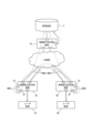
- FIG. 1 is a schematic diagram showing an example of an uninterrupted redundant switching system 100 according to the first embodiment.
- the uninterrupted redundant switching system 100 includes a user device UA, a user device UB, an uninterrupted redundant switching device 1A, an uninterrupted redundant switching device 1B, a first relay switch 3A, and a second relay switch. 3B, a monitoring network switch 4, and a monitoring device 5.
- the no-shutdown redundant switching system 100 has a configuration in which the monitoring device 5 does not communicate with one or more no-shutdown redundant switching devices that are different from the no-shutdown redundant switching devices 1A and 1B. In this case, the monitoring network switch 4 may not be provided.
- the user device UA and the uninterrupted redundant switching device 1A can directly communicate with each other.
- the user device UB and the uninterrupted redundant switching device 1B can directly communicate with each other.
- the uninterrupted redundant switching device 1A and the uninterrupted redundant switching device 1B communicate with each other via the first communication line NW1 through relaying by the first relay switch 3A.
- the uninterrupted redundant switching device 1A and the uninterrupted redundant switching device 1B connect to a second relay switch different from the first relay switch 3A via a second communication line NW2 different from the first communication line NW1. They communicate with each other by being relayed by the relay switch 3B.
- each of the non-interruption redundant switching device 1A and the non-interruption redundant switching device 1B and the monitoring device 5 are relayed by the first relay switch 3A or the second relay switch 3B and the monitoring network switch 4. communicate with each other by.
- the no-shutdown redundant switching device 1A and the no-shutdown redundant switching device 1B may be simply referred to as “no-shutdown device 1A” and “no-shutdown device 1B,” respectively.
- Each of the non-instantaneous redundant switching device 1A and the non-instantaneous redundant switching device 1B may be simply referred to as the "instantaneous interruption device 1.”
- each of the user device UA and the user device UB may be simply referred to as “user device U.”
- each of the first relay switch 3A and the second relay switch 3B may be simply referred to as "relay switch 3.”
- the user device UA and the user device UB are each configured by a computer including a controller, a memory, and a communication interface.
- the controller may be configured with dedicated hardware such as an ASIC (Application Specific Integrated Circuit) or an FPGA (Field-Programmable Gate Array), a processor, or a combination of both. good.
- Memory may be configured by registers in hardware such as ASIC or FPGA, or may be configured by HDD (Hard Disk Drive), SSD (Solid State Drive), EEPROM (Electrically Erasable Programmable Read-Only Memory), ROM (Read-Only Memory), etc. Memory), RAM (Random Access Memory), and the like.
- standards such as Ethernet (registered trademark), FDDI (Fiber Distributed Data Interface), and Wi-Fi (registered trademark) may be used for the communication interface.
- the user device UA and the user device UB transmit the main signal frame Fm to the instantaneous power outage device 1A and the instantaneous power outage device 1B, respectively. Further, the user equipment UA and the user equipment UB receive the main signal frame Fm from the instantaneous power outage device 1A and the instantaneous power outage device 1B, respectively.
- FIG. 1 shows an example in which the user device UA transmits a main signal frame Fm to the uninterrupted device 1A. Note that the present invention is not limited to this, and the user device UB may transmit the main signal frame Fm to the uninterrupted device 1B.
- the uninterrupted device 1A includes an access port 11, an identifier assigning section 12, an uninterrupted redundancy switching processing section (uninterruptible shutoff processing section) 13, a monitoring function section 14, and an identifier attaching section 12. It includes a deletion section 15, a first transport (first communication interface) 16, a second transport (second communication interface) 17, a signal distribution section 18, and an identifier deletion section 19.
- the access port 11, the first transport 16, and the second transport 17 are configured by communication interfaces.
- standards such as Ethernet (registered trademark), FDDI (Fiber Distributed Data Interface), and Wi-Fi (registered trademark) may be used for the communication interface.
- the identifier assigning unit 12, the non-stop processing unit 13, the monitoring function unit 14, the identifier assigning and deleting unit 15, the signal distributing unit 18, and the identifier deleting unit 19 are configured by a controller. Further, each functional section may be configured integrally with other functional sections, or may be configured as a separate body.
- the access port 11 transmits and receives the main signal frame Fm to and from the user device U via the communication line.
- the access port 11 included in the uninterrupted device 1A transmits and receives the main signal frame Fm to and from the user device UA.
- the access port 11 included in the uninterrupted device 1B transmits and receives the main signal frame Fm to and from the user device UB.
- the identifier assigning unit 12 shown in FIG. 2 assigns a main signal identifier IDm to the main signal frame Fm received from the user device U via the access port 11.
- the main signal identifier IDm is an identifier indicating that the frame to which the main signal identifier IDm is assigned is the main signal frame Fm.
- the uninterrupted processing unit 13 includes a duplicator 131 and a selector 132.
- the duplicator 131 copies the main signal frame Fm given the main signal identifier IDm.
- the duplicator 131 also generates a first main frame Fms1 in which a header HD for uninterrupted processing is added to a main signal frame Fm to which a main signal identifier IDm is added, which is the duplication source, and a main signal frame Fms1 to which a header HD for uninterrupted processing is added.
- a second main frame Fms2 is generated by adding a header HD for uninterrupted processing to the main signal frame Fm.
- the header HD for instantaneous interruption processing is information added to the main signal frame Fm, and is information for recognizing that the main signal frame Fm has been lost due to disconnection of a communication line or the like.
- the header HD for instantaneous interruption processing is, for example, information indicating the order in which the main signal frames Fm to which the header HD for instantaneous interruption processing is attached is transmitted, and may be, for example, a sequence number.
- the selector 132 selects a main frame to be transmitted to the user device U from the main frames received by each of the first transport 16 and the second transport 17 based on the header HD for uninterrupted processing. .
- the selector 132 can select the main frame according to any uninterrupted redundancy switching process.
- the monitoring function unit 14 generates a monitoring signal frame Fc.
- the monitoring signal frame Fc is a frame that is transmitted and received between the uninterrupted device 1 and the monitoring device 5, and is used for monitoring processing by the monitoring device 5 and the monitoring function section 14.
- the monitoring signal frame Fc can be a frame according to monitoring processing by the monitoring device 5 and the monitoring function section 14.
- the identifier addition/deletion unit 15 generates a monitoring frame Fcs by adding a monitoring signal identifier IDc indicating that the frame is a monitoring signal frame to the monitoring signal frame Fc.
- the supervisory signal identifier IDc is an identifier indicating that the frame to which the supervisory signal identifier IDc is assigned is a supervisory signal frame.
- the supervisory signal identifier IDc can be, for example, a VLAN (Virtual Local Area Network) identifier defined by IEEE (Institute of Electrical and Electronics Engineers) 802.1Q.
- the monitoring frame Fcs generated by the identifier addition/deletion unit 15 is transmitted by the first transport. That is, the identifier addition/deletion unit 15 causes the first transport 16 to transmit the monitoring frame Fcs. For example, the identifier addition/deletion unit 15 may control the signal distribution unit 18 to transmit the monitoring frame Fcs to the first transport 16.
- the first transport 16 transmits the first main frame Fms to the first relay switch 3A via the first communication line NW1.
- the first transport 16 also receives the main frame transmitted by the user device UB from the first relay switch 3A via the first communication line NW1.
- the second transport 17 transmits the second main frame Fms2 to the second relay switch 3B, which is different from the first relay switch 3A, via the second communication line NW2.
- the second transport 17 also receives the main frame transmitted by the user device UB from the second relay switch 3B via the second communication line NW2.
- first transport 16 and the second transport 17 transmits the monitoring frame Fcs to the relay switch 3.
- first transport 16 transmits the monitoring frame Fcs to the first relay switch 3A via the first communication line NW1.
- first transport 16 receives the monitoring frame Fcs transmitted by the monitoring device 5 from the first relay switch 3A via the first communication line NW1.
- the signal distribution unit 18 determines whether the signal received by the transport (in the first embodiment, the first transport 16) that transmits the monitoring frame Fcs is selected from among the first transport 16 and the second transport 17. Based on whether the identifier given to the frame is the main signal identifier IDm or the supervisory signal identifier IDc, it is determined whether the frame is the main frame Fms or the supervisory frame Fcs.
- the signal distribution unit 18 outputs the main frame Fms to the non-interruption processing unit 13 and outputs the monitoring frame Fcs to the monitoring function unit 14.
- the signal distribution unit 18 determines whether the identifier included in the frame received by the first transport 16 is the main signal identifier IDm or the supervisory signal identifier IDs. When determining that the identifier is the main signal identifier IDm, the signal distribution unit 18 determines that the frame is a main frame. Furthermore, when determining that the identifier is the supervisory signal identifier IDs, the signal distribution unit 18 determines that the frame is the supervisory frame Fcs.
- the signal distribution unit 18 determines that the frame is a main frame, it outputs the main frame to the selector 132 of the non-interruption processing unit 13.
- the signal distribution unit 18 determines that the frame is a monitoring frame Fcs, it outputs the monitoring frame Fcs to the identifier addition/deletion unit 15 .
- the identifier deletion unit 19 further deletes the main signal identifier IDm from the main frame Fms selected by the selector 132 and from which the header HD for uninterrupted processing has been deleted. Thereby, the above-mentioned access port 11 can transmit to the user device U the main signal frame Fm in which the header HD for instantaneous interruption processing and the main signal identifier IDm are deleted from the main frame Fms.
- the relay switch 3 receives the main frame transmitted by the uninterrupted device 1 via the communication line.
- the first relay switch 3A receives the main frame Fms1 transmitted from the first transport 16 of the uninterrupted device 1A via the first communication line NW1.
- the second relay switch 3B receives the main frame Fms2 transmitted from the second transport 17 of the uninterrupted device 1A via the second communication line NW2.
- the first relay switch 3A receives the main frame Fms1 transmitted from the first transport 16 of the uninterrupted device 1B via the first communication line NW1.
- the second relay switch 3B receives the main frame Fms2 transmitted from the second transport 17 of the uninterrupted device 1B via the first communication line NW1.
- the relay switch 3 receives the monitoring frame Fcs transmitted by the uninterrupted device 1 via the communication line.
- the first relay switch 3A receives the monitoring frame Fcs transmitted from the first transport 16 of the uninterrupted device 1A via the first communication line NW1.
- the first relay switch 3A receives the monitoring frame Fcs transmitted from the first transport 16 of the uninterrupted device 1B via the first communication line NW1.
- the relay switch 3 transmits the main frame Fms received from one non-shutdown device 1 to the other non-shutdown device 1, and sends the monitoring frame Fcs received from the non-shutdown device 1 via the monitoring network switch 4. The information is sent to the monitoring device 5.
- the relay switch 3 directly transmits the monitoring frame Fcs received from the uninterrupted device 1 to the monitoring device 5.
- the relay switch 3 determines whether the frame is a main frame Fms or a monitoring frame Fcs. For example, the relay switch 3 may determine whether the identifier included in the frame is the main signal identifier IDm or the supervisory signal identifier IDs. In such a configuration, when the relay switch 3 determines that the identifier is the main signal identifier IDm, it determines that the frame is the main frame Fms, and transmits the main frame Fms to the second uninterrupted device 1B. Send. Further, when the relay switch 3 determines that the identifier is the supervisory signal identifier IDc, the relay switch 3 determines that the frame is a supervisory frame Fcs, and transmits the supervisory frame Fcs to the supervisory network switch 4.
- the relay switch 3 determines whether the frame is a main frame Fms or a monitoring frame Fcs. For example, the relay switch 3 may determine whether the identifier included in the frame is the main signal identifier IDm or the supervisory signal identifier IDs. In such a configuration, when the relay switch 3 determines that the identifier is the main signal identifier IDm, it determines that the frame is the main frame Fms, and transmits the main frame Fms to the first uninterrupted device 1A. Send. Further, when the relay switch 3 determines that the identifier is the supervisory signal identifier IDc, the relay switch 3 determines that the frame is a supervisory frame Fcs, and transmits the supervisory frame Fcs to the supervisory network switch 4.
- the relay switch 3 transmits the monitoring signal frame Fc transmitted from the monitoring device 5 and relayed by the monitoring network switch 4 to the uninterrupted device 1.
- the relay switch 3 directly receives the monitoring signal frame Fc transmitted from the monitoring device 5. Then, the relay switch 3 transmits the monitoring frame Fcs to the uninterrupted device 1 corresponding to the destination included in the monitoring signal frame Fc. For example, when the destination included in the monitoring signal frame Fc is the user device UA, the relay switch 3 transmits the monitoring frame Fcs to the uninterrupted device 1A. Further, when the destination indicated by the monitoring signal frame Fc is the user device UB, the relay switch 3 transmits the monitoring frame Fcs to the uninterrupted device 1B.
- the monitoring network switch 4 is a relay capable of transmitting information to the uninterrupted device 1 corresponding to the user device U, which is the destination indicated by the monitoring signal frame Fc included in the monitoring frame Fcs transmitted from the monitoring device 5.
- a supervisory signal frame Fc is transmitted to the switch 3.
- the monitoring device 5 is configured by a computer including a memory, a controller, and a communication interface.
- the monitoring device 5 receives the monitoring frame Fcs transmitted from the uninterrupted device 1A via the first communication line NW1.
- the monitoring device 5 can perform known monitoring processing using the monitoring signal frame Fc included in the monitoring frame Fcs.
- the monitoring device 5 transmits a monitoring frame Fcs to the non-interruption device 1.
- the first transport 16 transmits the monitoring frame Fcs via the first communication line NW1, but this is not the case.
- the second transport 17 may transmit the monitoring frame Fcs via the second communication line NW2.
- the second transport 17 instead of the first transport 16 transmits the monitoring frame Fcs transmitted by the monitoring device 5 to the second relay switch via the second communication line NW2.
- the signal distribution unit 18 determines whether the frame received by the second transport 17 instead of the first transport 16 is a main frame or a monitoring frame Fcs.
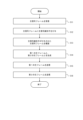
- FIG. 3A is a flowchart illustrating an example of an operation for transmitting a main frame in the uninterrupted device 1 according to the first embodiment.
- FIG. 3B is a flowchart illustrating an example of an operation for transmitting the monitoring frame Fcs in the uninterrupted device 1 according to the first embodiment.
- FIG. 4 is a flowchart showing an example of an operation for processing a received frame in the uninterrupted device 1 according to the first embodiment.
- the operation of the uninterruptible device 1 described with reference to FIGS. 3A, 3B, and 4 corresponds to the uninterruptible redundant switching method executed by the uninterruptible device 1 according to the first embodiment.
- step S11 the access port 11 receives the main signal frame Fm transmitted from the user device U.
- step S12 the identifier addition/deletion unit 15 adds a main signal identifier IDm to the main signal frame Fm received from the user device U, indicating that the main signal frame Fm is the main signal frame Fm.
- step S13 the uninterrupted processing unit 13 copies the main signal frame Fm to which the main signal identifier IDm has been added.
- step S14 the no-shutdown processing unit 13 generates the first main frame Fms1, which is the copy source main signal frame Fm to which the main signal identifier IDm is added, and the first main frame Fms1, which is the main signal frame Fm to which the no-shutdown processing header HD is added.
- a second main frame Fms2 is generated by adding a header HD for instantaneous interruption processing to the main signal frame Fm to which the main signal identifier IDm is added.
- step S15 the first main frame Fms1 is transmitted to the first relay switch 3A via the first communication line NW1.
- step S16 the second main frame Fms2 is transmitted to the second relay switch 3B different from the first relay switch 3A via the second communication line NW2.
- step S21 the monitoring function unit 14 generates a monitoring signal frame Fc.
- step S22 the identifier addition/deletion unit 15 generates a monitoring frame Fcs by adding a monitoring signal identifier IDc to the monitoring signal frame Fc to identify the monitoring signal frame Fc.
- step S23 only one of the first transport 16 and the second transport 17 transmits the monitoring frame Fcs to the relay switch 3.
- the first embodiment for example, only the first transport 16 transmits the monitoring frame Fcs to the relay switch 3.
- step S31 the first transport 16 and the second transport 17 receive the frame.
- step S32 the signal distribution unit 18 determines that the identifier given to the frame received by the transport that transmits the monitoring frame Fcs among the first transport 16 and the second transport 17 is the main signal identifier. Based on whether the frame is IDm or supervisory signal identifier IDc, it is determined whether the frame is main frame Fms or supervisory frame Fcs. That is, in the first embodiment, the signal distribution unit 18 determines whether the frame received by the first transport 16 is the main frame Fms.
- step S33 the no-disruption processing unit 13 converts the first transport 16 and the second transport based on the no-disruption processing header HD.
- a main frame to be transmitted to the user device U is selected from the main frames Fms received by each port 17.
- the instantaneous interruption processing unit 13 deletes the instantaneous interruption processing header HD from the selected main frame.
- step S34 the identifier deletion unit 19 deletes the main signal identifier IDm from the main frame Fms selected in step 31 and from which the header HD for uninterrupted processing has been deleted.
- step S35 the access port 11 transmits to the user device U the main signal frame Fm in which the main signal identifier IDm is deleted from the main frame Fms.
- step S36 the identifier addition/deletion unit 15 deletes the monitoring signal identifier IDc from the monitoring frame Fcs.
- step S37 the monitoring function unit 14 executes monitoring processing using the monitoring signal frame Fc from which the monitoring signal identifier IDc has been deleted.
- the uninterrupted device 1 assigns a main signal identifier IDm to the main signal frame Fm received from the user device U, indicating that the main signal frame Fm is the main signal frame Fm.
- a first transport 16 transmits the frame Fms1 to the first relay switch 3A, a second transport 17 transmits the second main frame Fms2 to the first relay switch 3A, and generates a supervisory signal frame Fc. and an identifier addition/deletion unit 15 that generates a monitoring frame Fcs in which a monitoring signal frame Fc is provided with a monitoring signal identifier IDc for identifying that the monitoring signal frame Fc is a monitoring signal frame Fc. Only one of the transport 16 and the second transport 17 transmits the monitoring frame Fcs to the relay switch 3.
- the uninterrupted device 1 can be remotely monitored with a simple configuration.
- the no-shutdown device 1 can transmit the supervisory signal frame Fc to the monitoring device 5 without performing the process of adding the no-shutdown processing header HD. Therefore, the processing load on the uninterrupted device 1 is reduced.
- the instantaneous interruption device 1 transmits the monitoring frame Fcs to which the instantaneous interruption processing header HD is not attached to the monitoring device 5 via one communication line, as shown in FIG. Furthermore, there is no need to provide an uninterrupted device between the monitoring network switch 4 and the relay switch 3. Therefore, the no-shutdown redundant switching system 100 including the no-shutdown device 1 can be easily configured.
- the uninterrupted device 1 determines whether the identifier given to the frame received by the first transport 16 and the second transport 17 is the main signal identifier IDm or the supervisory signal identifier IDc.
- the signal distribution unit 18 determines whether the frame is a main frame or a monitoring frame Fcs, outputs the main frame to the non-interruption processing unit 13, and outputs the monitoring frame Fcs to the monitoring function unit 14.
- the no-shutdown processing unit 13 selects a frame to be transmitted to the user device U based on the no-shutdown processing header HD included in the main frame
- the monitoring function unit 14 selects a frame to be transmitted to the user device U based on the no-shutdown processing header HD included in the main frame
- the monitoring function unit 14 Execute monitoring processing using .
- the monitoring function unit 14 performs monitoring processing based on the monitoring signal frame Fc included in the monitoring frame Fcs received via either of the two communication lines in communication using PRP. can be executed. Therefore, the uninterrupted device 1 does not need to provide a communication line NW91 for transmitting and receiving the supervisory signal frame Fc as shown in FIG. There is no need to provide a communication line NW92 to connect the access port AP. Therefore, the no-shutdown redundant switching system 100 including the no-shutdown device 1 can be easily configured.
- the uninterruptible redundant switching system 100 includes an uninterruptible apparatus 1A-1 and an uninterruptible apparatus 1B-in place of the uninterruptible apparatus 1A and 1B shown in FIG. 1.
- the same reference numerals are given to the same functional units as in the first embodiment, and the description thereof will be omitted.
- the instantaneous interruption device 1A-1 and the instantaneous interruption device 1B-1 may be simply referred to as the “instantaneous interruption device 1-1”.
- the uninterrupted redundant switching system 100 includes a monitoring device 5-1 instead of the monitoring device 5 shown in FIG.
- the uninterruptible device 1-1 includes an access port 11, an identifier assigning unit 12, an uninterruptible processor 13, a monitoring function unit 14, an identifier assigning and deleting unit 15, and a first transport 16, second transport 17, identifier deletion unit 19, line status information storage unit 20, first line monitoring function unit 21, second line monitoring function unit 22, line switching 23, a first signal distribution section 24, and a second signal distribution section 25.
- the line status information storage unit 20 is constituted by a memory.
- the first line monitoring function section 21, the second line monitoring function section 22, the first signal distribution section 24, and the second signal distribution section 25 are configured by a controller. Further, each functional section may be configured integrally with other functional sections, or may be configured as a separate body.
- the line status information storage unit 20 stores line status information.
- the line status information in the second embodiment is information indicating whether the first communication line NW1 is normal or not, and information indicating whether the second communication line NW2 is normal or not.
- the first communication line NW1 is a communication line that propagates the first main frame Fms1 transmitted by the first transport 16 to another uninterrupted device 1-1.
- the second communication line NW2 is a communication line different from the first communication line NW1, which propagates the second main frame transmitted by the second transport 17 to another uninterrupted device 1-1. .
- the first line monitoring function unit 21 determines whether the first communication line NW1 that propagates the first main frame Fms1 transmitted by the first transport 16 to another uninterrupted device 1-1 is normal. Determine whether or not.
- the first communication line NW1 is a communication line that connects the first uninterrupted device 1A-1 and the second uninterrupted device 1B-1.
- the first line monitoring function unit 21 determines that the first communication line NW1 is normal when the occurrence of disconnection is not detected in the first communication line NW1, and the first communication line NW1 If the occurrence of disconnection is detected in , it is determined that the first communication line NW1 is not normal.
- the first line monitoring function unit 21 may detect the occurrence of a disconnection in the first communication line NW1 using Ethernet Continuity Check defined in IEEE802.1ag and ITU-TY.1731.
- the first line monitoring function unit 21 controls the The information indicating whether or not the communication line NW1 is normal is changed. Specifically, when the first communication line NW1 changes from a state determined to be normal to a state determined to be abnormal, the first line monitoring function unit 21 controls the first communication line NW1. Change line status information to indicate that the line is unhealthy. Further, the first line monitoring function unit 21 determines that the first communication line NW1 is normal when the first communication line NW1 changes from a state determined to be abnormal to a state determined to be normal. Change line status information to indicate that
- the second line monitoring function unit 22 is configured to connect a second communication line different from the first communication line NW1 to propagate the second main frame transmitted by the second transport 17 to another uninterrupted device 1-1. It is determined whether the communication line NW2 is normal.
- the second communication line NW2 is a communication line that connects the first uninterrupted device 1A-1 and the second uninterrupted device 1B-1.
- the specific process for the second line monitoring function unit 22 to monitor the normality of the second communication line NW2 is that the first line monitoring function unit 21 monitors the normality of the first communication line NW1.
- the line switching unit 23 switches the transport for transmitting the monitoring frame Fcs to the first transport 16, and switches the transport for transmitting the monitoring frame Fcs to the first transport 16, and switches the transport when the first communication line NW1 is not normal. If it is determined that the second communication line NW2 is normal, the transport for transmitting the monitoring frame Fcs is switched to the second transport 17.
- the line switching unit 23 determines whether the line status information stored in the line status information storage unit 20 indicates that the first communication line NW1 is normal. When it is determined that the first communication line NW1 is normal, the line switching unit 23 switches the transport for transmitting the monitoring frame Fcs to the first transport 16. For example, the line switching unit 23 may control the first signal distribution unit 24 to switch the transport for transmitting the monitoring frame Fcs to the first transport 16.
- the line switching unit 23 determines whether the line status information indicates that the second communication line NW2 is normal. do. If it is determined that the line status information indicates that the second communication line NW2 is normal, the line switching unit 23 switches the transport for transmitting the monitoring frame Fcs to the second transport 17. . For example, the line switching unit 23 may control the second signal distribution unit 25 to switch the transport for transmitting the monitoring frame Fcs to the second transport 17.
- the line switching unit 23 switches both the first transport 16 and the second transport 17 for monitoring purposes. Do not transmit frame Fcs. Note that if it is determined that the line status information indicates that the second communication line NW2 is not normal, the line switching unit 23 may output a frame indicating an error to a port (not shown). Thereby, the administrator of the uninterrupted redundant switching system 100 can restore the first communication line NW1 and the second communication line NW2.
- the line switching unit 23 switches the transport (the first transport 16 or the second transport 17) for transmitting the monitoring frame Fcs due to changes in the normality of the communication line. , notifies the monitoring network switch 4 of a change in the communication line (first communication line NW1 or second communication line NW2) through which the monitoring frame Fcs is transmitted.
- the line switching unit 23 may use GARP (Gratuitous Address Resolution Protocol).
- GARP Gramuitous Address Resolution Protocol
- the monitoring network switch 4 transmits the monitoring frame Fcs transmitted from the monitoring device 5 to the uninterrupted device 1-1 via the communication line corresponding to the transport switched by the line switching unit 23.
- the MAC (Media Access Control) address table can be rewritten to
- the first signal distribution unit 24 determines that when the first transport 16 is transmitting the monitoring frame Fcs by switching the line switching unit 23, the frame received by the first transport 16 is the main frame. , or the monitoring frame Fcs. Specifically, the first signal distribution unit 24 determines whether the identifier included in the frame received by the first transport 16 is the main signal identifier IDm or the supervisory signal identifier IDs. When the signal distribution unit 18 determines that the identifier is the main signal identifier IDm, it determines that the frame is the main frame, and when it determines that the identifier is the supervisory signal identifier IDs, the frame is the supervisory frame Fcs. It is determined that
- the first signal distribution unit 24 determines that the frame is a main frame, it outputs the main frame to the selector 132 of the non-interruption processing unit 13.
- the first signal distribution unit 24 determines that the frame is a monitoring frame Fcs, it outputs the monitoring frame Fcs to the identifier addition/deletion unit 15 .
- the second signal distribution unit 25 determines that when the second transport 17 is transmitting the monitoring frame Fcs by switching the line switching unit 23, the frame received by the second transport 17 is the main frame. , or the monitoring frame Fcs.
- the specific processing by the second signal distribution section 25 is the same as the specific processing by the first signal distribution section 24.
- the monitoring device 5-1 receives information transmitted from the uninterrupted device 1A through the communication line corresponding to the transport switched by the line switching unit 23 among the first transport 16 and the second transport 17.
- the received monitoring frame Fcs is received.
- the monitoring device 5-1 also monitors the uninterrupted device 1 via the communication line corresponding to the transport switched by the line switching unit 23 among the first transport 16 and the second transport.
- frame Fcs is transmitted. Note that, as described above, by rewriting the MAC address table in the monitoring network switch 4, the monitoring device 5-1 can operate without interruption via the communication line corresponding to the transport switched by the line switching unit 23.
- a monitoring frame Fcs can be transmitted to the device 1.
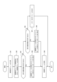
- FIG. 6 is a flowchart showing an example of the operation for transmitting the monitoring frame Fcs in the uninterrupted device 1-1 according to the second embodiment.
- the operation of the uninterruptible device 1-1 described with reference to FIG. 6 corresponds to the uninterruptible redundant switching method executed by the uninterruptible device 1 according to the second embodiment.
- step S41 the monitoring function unit 14 generates a monitoring signal frame Fc.
- step S42 the identifier addition/deletion unit 15 generates a monitoring frame Fcs by adding a monitoring signal identifier IDc to the monitoring signal frame Fc to identify that it is a monitoring signal frame.
- step S43 the line switching unit 23 determines whether the first communication line NW1 through which the main frame transmitted by the first transport 16 is propagated to another uninterruptible device 1-1 is normal. do. Specifically, the line switching unit 23 refers to the line status information of the first communication line NW1 stored in the line status information storage unit 20 based on the determination of the first line monitoring function unit 21. It may be determined whether the first communication line NW1 is normal or not.
- the line switching unit 23 switches the transport for transmitting the monitoring frame Fcs to the first transport 16 in step S44.
- the line switching unit 23 may control the first signal distribution unit 24 to switch the transport to which the monitoring frame Fcs is transmitted to the first transport 16.
- step S45 the line switching unit 23 transfers the main frame transmitted by the second transport 17 to the other uninterruptible device 1-1. It is determined whether the second communication line NW2, which is different from the first communication line NW1, is normal. Specifically, the line switching unit 23 refers to the line status information of the second communication line NW2 stored in the line status information storage unit 20 based on the determination of the second line monitoring function unit 22. , it may be determined whether the second communication line NW2 is normal.
- the line switching unit 23 switches the transport for transmitting the monitoring frame Fcs to the first transport 16 in step S46.
- the line switching unit 23 may control the second signal distribution unit 25 to switch the transport to which the monitoring frame Fcs is transmitted to the second transport 17.
- step S47 the line switching unit 23 causes a port (not shown) to output a frame indicating an error.
- step S48 the switched transport transmits the monitoring frame Fcs.
- the operation for the instantaneous uninterruptible device 1-1 according to the second embodiment to transmit the main frame is the same as the operation for the instantaneous uninterruptible device 1 according to the first embodiment to transmit the main frame. It is.
- the operation for processing the frame received by the uninterruptible device 1-1 according to the second embodiment is the same as the operation for processing the frame received by the uninterruptible device 1 according to the first embodiment. The same is true.
- the line switching unit 23 of the first transport 16 and the second transport 17 selects the monitoring frame based on the line status information.
- the transport that transmitted the Fcs receives the monitoring frame Fcs.
- the uninterruptible device 1-1 transmits the main frame transmitted by the first transport 16 to the other uninterruptible devices 1-1.
- a second line monitoring function unit 22 that determines whether or not the second communication line NW2 is normal; and if it is determined that the first communication line NW1 is normal, causes the monitoring frame Fcs to be transmitted.
- the mobile phone further includes a line switching unit 23 that switches the transport to be transmitted to the second transport 17.
- the uninterrupted device 1-1 can transmit the monitoring frame Fcs to the monitoring device 5 even if either the first communication line NW1 or the second communication line NW2 is not normal. Therefore, the uninterrupted device 1-1 can be appropriately monitored by the monitoring device 5 even when either the first communication line NW1 or the second communication line NW2 is not normal.
- the no-shutdown redundant switching system 100 includes a no-shutdown device 1A-2 and a no-shutdown device 1B- in place of the no-shutdown device 1A and the no-shutdown device 1B shown in FIG. 2.
- the same reference numerals are added to the same functional units as in the first embodiment and the second embodiment, and the description thereof will be omitted.
- the instantaneous power outage device 1A-2 and the instantaneous power outage device 1B-2 may be simply referred to as "the instantaneous power outage device 1-2.”
- the uninterrupted redundant switching system 100 includes a monitoring device 5-2 instead of the monitoring device 5 shown in FIG.
- each functional section may be configured integrally with other functional sections, or may be configured as a separate body.
- the uninterrupted device 1-2 includes an access port 11, an identifier assigning unit 12, an uninterruptible processor 13, a monitoring function unit 14, an identifier assigning and deleting unit 15, and a first transport 16, second transport 17, identifier deletion unit 19, line status information storage unit 20-2, line switching unit 23-2, first signal distribution unit 24, and second It includes a signal distribution section 25 and a line monitoring function section 26.
- the line status information storage section 20-2 is constituted by a memory.
- the line switching unit 23-2 and the line monitoring function unit 26 are configured by a controller.
- the line status information storage unit 20-2 stores line status information.
- the line status information in the third embodiment is information indicating whether the third communication line NW3 is normal or not, and information indicating whether the fourth communication line NW4 is normal or not.
- the third communication line is a communication line that propagates the frame transmitted by the first transport 16 to the monitoring device 5.
- the fourth communication line is a communication line that propagates the frame transmitted by the second transport 17 to the monitoring device 5.
- the portion from the uninterruptible device 1 to the relay switch 3 in the third communication line NW3 is the portion from the uninterruptible device 1 to the relay switch 3 in the first communication line NW1 described above. It is the part itself.
- the portion from the uninterrupted device 1 to the relay switch 3 in the fourth communication line NW4 is the same portion from the uninterrupted device 1 to the relay switch 3 in the second communication line NW2 described above.
- the line monitoring function unit 26 determines whether the third communication line NW3, which propagates the monitoring frame Fcs transmitted by the first transport 16 to the monitoring device 5, is normal.
- the line monitoring function unit 26 determines whether the fourth communication line NW4, which propagates the frame transmitted by the second transport 17 to the monitoring device 5, is normal.
- the line monitoring function unit 26 determines that the third communication line NW3 is normal when the occurrence of disconnection is not detected in the third communication line NW3, and detects the disconnection in the third communication line NW3. If the occurrence is detected, it is determined that the third communication line NW3 is not normal. For example, the line monitoring function unit 26 causes the first transport 16 to transmit a PING (Packet InterNet Groper) specified in RFC (Request For Comments) 792 to the monitoring device 5, thereby transmitting the third The occurrence of disconnection in the communication line NW3 may also be determined. Specifically, if the first transport 16 transmits a PING to the monitoring device 5 and then receives a PING response, the line monitoring function unit 26 determines that no disconnection has occurred in the third communication line NW3. If it is determined that the PING response is not received, it can be determined that a disconnection has occurred in the third communication line NW3.
- PING Packet InterNet Groper
- the line monitoring function unit 26 detects the third communication line in the line status information stored in the line status information storage unit 20-2. Information indicating whether line NW3 is normal is changed. Specifically, when the third communication line NW3 changes from a state where it is determined to be normal to a state where it is determined that it is not normal, the line monitoring function unit 26 determines that the third communication line NW3 is not normal. Change the line status information to indicate . Further, when the third communication line NW3 changes from a state where it is determined to be not normal to a state where it is determined to be normal, the line monitoring function unit 26 indicates that the third communication line NW3 is normal. Change the line status information as follows.
- the specific process for the line monitoring function unit 26 to monitor the normality of the fourth communication line NW4 is the same as the specific process for monitoring the normality of the third communication line NW3.
- the line switching unit 23-2 switches the transport for transmitting the monitoring frame Fcs to either the first transport 16 or the second transport 17 based on the normality of the communication line. Specifically, the line switching unit 23-2 determines whether the line status information stored in the line status information storage unit 20-2 indicates that the third communication line NW3 is normal. do. When it is determined that the line status information indicates that the third communication line NW3 is normal, the line switching unit 23-2 switches the transport for transmitting the monitoring frame Fcs to the first transport 16. Switch to For example, the line switching unit 23-2 may control the first signal distribution unit 24 to switch the transport for transmitting the monitoring frame Fcs to the first transport 16.
- the line switching unit 23-2 determines that the line status information indicates that the fourth communication line NW4 is normal. Determine whether or not it is shown. When it is determined that the line status information indicates that the fourth communication line NW4 is normal, the line switching unit 23-2 switches the transport for transmitting the monitoring frame Fcs to the second transport 17. Switch to For example, the line switching unit 23-2 may control the second signal distribution unit 25 to switch the transport for transmitting the monitoring frame Fcs to the second transport 17.
- the line switching unit 23 controls the monitoring of both the first transport 16 and the second transport 17. Do not transmit frame Fcs. Further, when the line switching unit 23-2 determines that the line status information indicates that the fourth communication line NW4 is not normal, the line switching unit 23-2 may output a frame indicating an error to a port (not shown). good. This allows the administrator of the uninterrupted redundant switching system 100 to restore the third communication line NW3 and the fourth communication line NW4.
- the line switching unit 23-2 selects the transport (the first transport 16 or the second transport 17) for transmitting the monitoring frame Fcs as the normality of the communication line changes.
- the monitoring network switch 4 is notified of the change in the communication line (third communication line NW3 or fourth communication line NW4) that transmits the monitoring frame Fcs.
- the line switching unit 23-2 may use GARP.
- the monitoring network switch 4 transmits the monitoring frame Fcs transmitted from the monitoring device 5 to the uninterrupted device 1-2 via the communication line corresponding to the transport switched by the line switching unit 23-2.
- the MAC address table can be rewritten so as to be transmitted.
- the monitoring device 5-2 transmits data from the uninterrupted device 1A through the communication line corresponding to the transport switched by the line switching unit 23-2, among the first transport 16 and the second transport.
- the received monitoring frame Fcs is received.
- the monitoring device 5-2 connects the uninterruptible device 1 to The monitoring frame Fcs is sent to.
- the MAC address table is rewritten in the monitoring network switch 4, so that the monitoring device 5-2 is able to perform communication via the communication line corresponding to the transport switched by the line switching unit 23-2.
- the monitoring frame Fcs can be transmitted to the uninterrupted device 1.
- FIG. 8 is a flowchart showing an example of the operation for transmitting the monitoring frame Fcs in the uninterrupted device 1-2 according to the third embodiment.
- the operation of the uninterruptible device 1-2 described with reference to FIG. 8 corresponds to the uninterruptible redundant switching method executed by the uninterruptible device 1 according to the third embodiment.
- step S51 the monitoring function unit 14 generates a monitoring signal frame Fc.
- step S52 the identifier addition/deletion unit 15 generates a monitoring frame Fcs by adding a monitoring signal identifier IDc to the monitoring signal frame Fc to identify that it is a monitoring signal frame.
- step S53 the line switching unit 23-2 determines whether the third communication line NW3 through which the monitoring frame Fcs transmitted by the first transport 16 is propagated to the monitoring device 5 is normal. Specifically, the line switching unit 23-2 switches the third communication line by referring to the line status information stored in the line status information storage unit 20-2 based on the determination by the line monitoring function unit 26. It may also be determined whether NW3 is normal.
- the line switching unit 23-2 switches the transport for transmitting the monitoring frame Fcs to the first transport 16 in step S54.
- the line switching unit 23-2 may control the first signal distribution unit 24 to switch the transport to which the monitoring frame Fcs is transmitted to the first transport 16.
- step S53 If it is determined in step S53 that the third communication line NW3 is not normal, the line switching unit 23-2 propagates the monitoring frame transmitted by the second transport 17 to the monitoring device 5 in step S55. , it is determined whether the fourth communication line NW4, which is different from the third communication line NW3, is normal. Specifically, the line switching unit 23-2 switches the fourth communication line by referring to the line status information stored in the line status information storage unit 20-2 based on the determination by the line monitoring function unit 26. It may also be determined whether NW4 is normal.
- the line switching unit 23-2 switches the transport for transmitting the monitoring frame Fcs to the second transport 17 in step S56.
- the line switching unit 23-2 may control the second signal distribution unit 25 to switch the transport to which the monitoring frame Fcs is transmitted to the second transport 17.
- step S57 the line switching unit 23-2 outputs a frame indicating an error to a port (not shown).
- step S58 the switched transport transmits the monitoring frame.
- the operation for the instantaneous uninterruptible device 1-2 according to the third embodiment to transmit the main frame is similar to the operation for the instantaneous uninterruptible device 1 according to the first embodiment to transmit the main frame. It is.
- the operation for processing the received frame by the uninterruptible device 1-2 according to the third embodiment is the same as the operation for processing the frame received by the uninterruptible device 1 according to the first embodiment. The same is true.
- the line switching unit 23-2 of the first transport 16 and the second transport 17 performs monitoring based on the line status information.
- the transport that caused the frame Fcs to be sent receives the frame.
- the uninterrupted device 1-2 uses the third communication line to propagate the monitoring frame Fcs transmitted by the first transport 16 to the monitoring device 5.
- a line monitoring function that determines whether the NW3 is normal and determines whether the fourth communication line NW4 that propagates the frame transmitted by the second transport 17 to the monitoring device 5 is normal. 26 and the third communication line NW3 are determined to be normal, the first transport 16 is caused to transmit the monitoring frame Fcs, and when it is determined that the third communication line NW3 is not normal. If it is determined that the fourth communication line NW4 is normal, a line switching unit 23-2 is further provided that switches the transport for transmitting the monitoring frame Fcs to the first transport 16.
- the uninterrupted device 1-2 and the uninterrupted device 1-1 can be configured to use the monitoring device 5 for monitoring even when either the third communication line NW3 or the fourth communication line NW4 is not normal. Frame Fcs can be transmitted. Therefore, the uninterrupted device 1-1 can be appropriately monitored by the monitoring device 5 even when either the third communication line NW3 or the fourth communication line NW4 is not normal.
- FIG. 9 is a block diagram showing a schematic configuration of the computers 101 each functioning as the uninterrupted device 1.
- the computers functioning as the non-instantaneous device 1-1 and the non-instantaneous device 1-2 may also be configured similarly to the computer 101.
- the computer 101 may be a general-purpose computer, a dedicated computer, a workstation, a PC (Personal Computer), an electronic notepad, or the like.
- Program instructions may be program code, code segments, etc. to perform necessary tasks.
- the computer 101 includes a processor 110, a ROM (Read Only Memory) 120, a RAM (Random Access Memory) 130, a storage 140, an input section 1050, an output section 1060, and a communication interface ( I/F) 170.
- the processor 110 is a CPU (Central Processing Unit), MPU (Micro Processing Unit), GPU (Graphics Processing Unit), DSP (Digital Signal Processor), SoC (System on a Chip), etc., and may be of the same or different type. It may be configured with a plurality of processors.
- the processor 110 controls each component and executes various calculation processes. That is, the processor 110 reads a program from the ROM 120 or the storage 140 and executes the program using the RAM 130 as a work area. The processor 110 controls each of the above components and performs various arithmetic operations according to programs stored in the ROM 120 or the storage 140. In the embodiments described above, the program according to the present disclosure is stored in the ROM 120 or the storage 140.
- the program may be stored in a storage medium readable by the computer 101. Using such a storage medium, it is possible to install a program on the computer 101.
- the storage medium in which the program is stored may be a non-transitory storage medium.
- the non-temporary storage medium is not particularly limited, and may be, for example, a CD-ROM, a DVD-ROM, a USB (Universal Serial Bus) memory, or the like. Further, this program may be downloaded from an external device via a network.
- the ROM 120 stores various programs and various data.
- the RAM 130 temporarily stores programs or data as a work area.
- the storage 140 is configured with an HDD (Hard Disk Drive) or an SSD (Solid State Drive), and stores various programs including an operating system and various data.
- the input unit 1050 includes one or more input interfaces that accept a user's input operation and obtain information based on the user's operation.
- the input unit 1050 is a pointing device, a keyboard, a mouse, etc., but is not limited to these.
- the output unit 1060 includes one or more output interfaces that output information.
- the output unit 1060 is a display that outputs information as a video or a speaker that outputs information as an audio, but is not limited to these.
- the output unit 1060 also functions as the input unit 1050 if it is a touch panel display.
- the communication interface (I/F) 170 is an interface for communicating with an external device.
- a no-shutdown redundant switching device that communicates with another no-shutdown redundant switching device via a first communication line and a second communication line using a no-shutdown redundant switching process, comprising a controller, a first communication interface, and a second communication interface,
- the controller includes: Adding a main signal identifier indicating that the main signal frame is a main signal frame to the main signal frame received from the user equipment, A header for non-interruption processing indicating the order in which the main signal frames are to be transmitted by duplicating the main signal frame to which the main signal identifier has been attached, and to the main signal frame to which the main signal identifier has been attached, which is a copy source.
- a first main frame to which the main signal identifier is attached and a second main signal frame to which a header for non-interruption processing indicating the order in which the main signal frames are transmitted is attached to the duplicated main signal frame to which the main signal identifier is attached.
- the controller includes: Generates a supervisory signal frame, generating a monitoring frame in which a monitoring signal identifier for identifying that the monitoring signal frame is a monitoring signal frame is added to the monitoring signal frame; Only one of the first communication interface and the second communication interface transmits the monitoring frame via the corresponding first communication line or the second communication line. Redundant switching device.
- the controller includes: Of the first transport and the second transport, an identifier given to a frame received by a transport that transmits the monitoring frame is the main signal identifier or the monitoring signal identifier. determine whether the frame is the main frame or the monitoring frame, output the main frame to the non-interruption processing unit, and output the monitoring frame to the monitoring function unit. death,
- the no-shutdown processing unit selects a main frame to be transmitted to the user device based on a no-shutdown processing header included in the main frame,
- the uninterrupted redundant switching device according to Supplementary Note 1, wherein the monitoring function unit executes monitoring processing using the monitoring frame.
- the controller includes: determining whether a first communication line that propagates the first main frame transmitted by the first transport to another uninterrupted redundant switching device is normal; determining whether a second communication line that propagates the second main frame transmitted by the second transport to the other uninterrupted redundant switching device is normal; If it is determined that the first communication line is normal, the transport for transmitting the monitoring frame is switched to the first transport, and if it is determined that the first communication line is not normal, and if the second communication line is determined to be normal, the transport for transmitting the monitoring frame is switched to the second transport. Switching device.
- the controller includes: It is determined whether the third communication line that propagates the monitoring frame transmitted by the first transport to the monitoring device is normal, and the frame transmitted by the second transport is transmitted to the monitoring device. Determining whether the fourth communication line to be propagated to the monitoring device is normal; If it is determined that the third communication line is normal, the transport for transmitting the monitoring frame is switched to the first transport, and if it is determined that the third communication line is not normal, and the fourth communication line is determined to be normal, the transport for transmitting the monitoring frame is switched to the second transport, as described in any one of Supplementary Notes 1 to 3. Uninterrupted redundant switching device.
- a first main frame to which the main signal identifier is attached and a second main signal frame to which a header for non-interruption processing indicating the order in which the main signal frames are transmitted is attached to the duplicated main signal frame to which the main signal identifier is attached.
- the second main frame is transmitted to a second relay switch different from the first relay switch via the second communication line by a second transport different from the first transport.
- a redundant switching device comprising a controller, a first communication interface, and a second communication interface
- the controller includes: Adding a main signal identifier indicating that the main signal frame is a main signal frame to the main signal frame received from the user equipment, A header for non-interruption processing indicating the order in which the main signal frames are to be transmitted by duplicating the main signal frames to which the main signal identifiers have been attached, and to which the main signal frames to which the main signal identifiers have been attached are the duplication source.
- a first main frame to which the main signal identifier is attached and a second main signal frame to which a header for non-stop processing indicating the order in which the main signal frames are transmitted is attached to the duplicated main signal frame to which the main signal identifier is attached.
- the controller includes: Generates a supervisory signal frame, generating a monitoring frame in which a monitoring signal identifier for identifying that the monitoring signal frame is a monitoring signal frame is added to the monitoring signal frame; Only one of the first communication interface and the second communication interface transmits the monitoring frame via the corresponding first communication line or the second communication line.
- Momentary interruption redundant switching system [Additional note 7] A non-temporary storage medium storing a program executable by a computer, the non-temporary storage medium storing a program for causing the computer to operate as the uninterrupted redundant switching device according to Supplementary Note 1 or 2.
- Uninterrupted redundant switching device (uninterrupted device) 3, 3A, 3B Relay switch 4 Monitoring network switch 5 Monitoring device 11 Access port 12 Identifier assigning section 13 No-shutdown redundancy switching processing section (no-shutdown processing section) 14 Monitoring function unit 15 Identifier addition/deletion unit 16 First transport 17 Second transport 18 Signal distribution unit 19 Identifier deletion unit 20, 20-2 Line status information storage unit 21 First line monitoring function unit 22 Second Line monitoring function unit 23, 23-2 Line switching unit 24 First signal distribution unit 25 Second signal distribution unit 26 Line monitoring function unit 100 Uninterrupted redundant switching system 101 Computer 110 Processor 120 ROM 130 RAM 131 Duplicator 132 Selector 140 Storage 150 Input section 160 Output section 170 Communication interface 180 Bus UA, UB User device
Landscapes
- Engineering & Computer Science (AREA)
- Computer Networks & Wireless Communication (AREA)
- Signal Processing (AREA)
- Data Exchanges In Wide-Area Networks (AREA)
Priority Applications (2)
| Application Number | Priority Date | Filing Date | Title |
|---|---|---|---|
| PCT/JP2022/022686 WO2023233666A1 (ja) | 2022-06-03 | 2022-06-03 | 無瞬断冗長切替装置、無瞬断冗長切替方法、無瞬断冗長切替システム、及びプログラム |
| JP2024524143A JP7714844B2 (ja) | 2022-06-03 | 2022-06-03 | 無瞬断冗長切替装置、無瞬断冗長切替方法、無瞬断冗長切替システム、及びプログラム |
Applications Claiming Priority (1)
| Application Number | Priority Date | Filing Date | Title |
|---|---|---|---|
| PCT/JP2022/022686 WO2023233666A1 (ja) | 2022-06-03 | 2022-06-03 | 無瞬断冗長切替装置、無瞬断冗長切替方法、無瞬断冗長切替システム、及びプログラム |
Publications (1)
| Publication Number | Publication Date |
|---|---|
| WO2023233666A1 true WO2023233666A1 (ja) | 2023-12-07 |
Family
ID=89026254
Family Applications (1)
| Application Number | Title | Priority Date | Filing Date |
|---|---|---|---|
| PCT/JP2022/022686 Ceased WO2023233666A1 (ja) | 2022-06-03 | 2022-06-03 | 無瞬断冗長切替装置、無瞬断冗長切替方法、無瞬断冗長切替システム、及びプログラム |
Country Status (2)
| Country | Link |
|---|---|
| JP (1) | JP7714844B2 (https=) |
| WO (1) | WO2023233666A1 (https=) |
Citations (2)
| Publication number | Priority date | Publication date | Assignee | Title |
|---|---|---|---|---|
| JP2016225707A (ja) * | 2015-05-27 | 2016-12-28 | 三菱電機株式会社 | パケット転送装置 |
| JP2019047231A (ja) * | 2017-08-31 | 2019-03-22 | 富士通株式会社 | 伝送装置および障害検出方法 |
-
2022
- 2022-06-03 JP JP2024524143A patent/JP7714844B2/ja active Active
- 2022-06-03 WO PCT/JP2022/022686 patent/WO2023233666A1/ja not_active Ceased
Patent Citations (2)
| Publication number | Priority date | Publication date | Assignee | Title |
|---|---|---|---|---|
| JP2016225707A (ja) * | 2015-05-27 | 2016-12-28 | 三菱電機株式会社 | パケット転送装置 |
| JP2019047231A (ja) * | 2017-08-31 | 2019-03-22 | 富士通株式会社 | 伝送装置および障害検出方法 |
Also Published As
| Publication number | Publication date |
|---|---|
| JP7714844B2 (ja) | 2025-07-30 |
| JPWO2023233666A1 (https=) | 2023-12-07 |
Similar Documents
| Publication | Publication Date | Title |
|---|---|---|
| JP3224745B2 (ja) | 高信頼化ネットワークシステム及びサーバ切り替え方法 | |
| JP2006129446A (ja) | フォールト・トレラント・ネットワーク・アーキテクチャ | |
| CN105515812A (zh) | 资源的故障处理方法及装置 | |
| JP7348983B2 (ja) | 負荷分散システム、方法、装置、電子機器及び記憶媒体 | |
| CN104243205A (zh) | 一种虚拟交换机故障时的报文处理方法和设备 | |
| CN112398689B (zh) | 网络恢复方法、装置、存储介质及电子设备 | |
| CN114465948B (zh) | 主备容灾方法、装置、设备及介质 | |
| CN115225634A (zh) | 虚拟网络下的数据转发方法、装置及计算机程序产品 | |
| CN107465611A (zh) | Sdn控制器和交换机控制链路的保护倒换方法及装置 | |
| CN108650337B (zh) | 一种服务器探测方法、系统及存储介质 | |
| CN109981437B (zh) | 一种基于vpc的多数据中心互通方法及相关设备 | |
| CN109687943B (zh) | 一种双机备份冗余控制系统 | |
| US10462848B2 (en) | Non-transitory computer readable recording medium, communication method and communication device | |
| JP7714844B2 (ja) | 無瞬断冗長切替装置、無瞬断冗長切替方法、無瞬断冗長切替システム、及びプログラム | |
| US20210250235A1 (en) | Diagram generation method and storage medium | |
| CN110391987A (zh) | 从运营商边缘设备集合中选择指定转发器的方法、设备及计算机可读介质 | |
| JP4133738B2 (ja) | 高速ネットワークアドレス引継ぎ方法、ネットワーク装置及びプログラム | |
| CN109218179A (zh) | 负载分担方法及装置、交换机及计算机可读存储介质 | |
| CN109731345B (zh) | 语音处理方法及装置、电子设备、存储介质 | |
| CN119473720A (zh) | 一种数据备份方法、装置、电子设备及存储介质 | |
| CN114153655B (zh) | 容灾系统创建方法、容灾方法、装置、设备及介质 | |
| JP4378205B2 (ja) | ブレード型ネットワーク中継装置 | |
| CN111092770A (zh) | 一种虚拟网络管理方法及电子设备 | |
| JPH1027146A (ja) | 通信処理装置及び通信処理方法 | |
| CN103457766B (zh) | 一种堆叠分裂时管理设备的方法及装置 |
Legal Events
| Date | Code | Title | Description |
|---|---|---|---|
| 121 | Ep: the epo has been informed by wipo that ep was designated in this application |
Ref document number: 22944943 Country of ref document: EP Kind code of ref document: A1 |
|
| WWE | Wipo information: entry into national phase |
Ref document number: 2024524143 Country of ref document: JP |
|
| NENP | Non-entry into the national phase |
Ref country code: DE |
|
| 122 | Ep: pct application non-entry in european phase |
Ref document number: 22944943 Country of ref document: EP Kind code of ref document: A1 |