WO2023229044A1 - Feuille de commande de transmission de chaleur et bloc-batterie - Google Patents
Feuille de commande de transmission de chaleur et bloc-batterie Download PDFInfo
- Publication number
- WO2023229044A1 WO2023229044A1 PCT/JP2023/019812 JP2023019812W WO2023229044A1 WO 2023229044 A1 WO2023229044 A1 WO 2023229044A1 JP 2023019812 W JP2023019812 W JP 2023019812W WO 2023229044 A1 WO2023229044 A1 WO 2023229044A1
- Authority
- WO
- WIPO (PCT)
- Prior art keywords
- heat transfer
- transfer suppressing
- particles
- inorganic
- suppressing sheet
- Prior art date
Links
- 239000010954 inorganic particle Substances 0.000 claims abstract description 108
- 238000012546 transfer Methods 0.000 claims description 197
- 239000000835 fiber Substances 0.000 claims description 183
- 239000002245 particle Substances 0.000 claims description 81
- VYPSYNLAJGMNEJ-UHFFFAOYSA-N Silicium dioxide Chemical compound O=[Si]=O VYPSYNLAJGMNEJ-UHFFFAOYSA-N 0.000 claims description 76
- 239000011368 organic material Substances 0.000 claims description 73
- 238000002844 melting Methods 0.000 claims description 63
- 230000008018 melting Effects 0.000 claims description 63
- 239000012784 inorganic fiber Substances 0.000 claims description 48
- -1 polyethylene terephthalate Polymers 0.000 claims description 32
- 238000000034 method Methods 0.000 claims description 26
- GWEVSGVZZGPLCZ-UHFFFAOYSA-N Titan oxide Chemical compound O=[Ti]=O GWEVSGVZZGPLCZ-UHFFFAOYSA-N 0.000 claims description 20
- 230000001629 suppression Effects 0.000 claims description 17
- 239000011148 porous material Substances 0.000 claims description 15
- 229920000139 polyethylene terephthalate Polymers 0.000 claims description 12
- 239000005020 polyethylene terephthalate Substances 0.000 claims description 12
- 239000004743 Polypropylene Substances 0.000 claims description 11
- 229920001155 polypropylene Polymers 0.000 claims description 11
- XLOMVQKBTHCTTD-UHFFFAOYSA-N Zinc monoxide Chemical compound [Zn]=O XLOMVQKBTHCTTD-UHFFFAOYSA-N 0.000 claims description 10
- MCMNRKCIXSYSNV-UHFFFAOYSA-N Zirconium dioxide Chemical compound O=[Zr]=O MCMNRKCIXSYSNV-UHFFFAOYSA-N 0.000 claims description 10
- 238000003466 welding Methods 0.000 claims description 10
- 239000004677 Nylon Substances 0.000 claims description 9
- PNEYBMLMFCGWSK-UHFFFAOYSA-N aluminium oxide Inorganic materials [O-2].[O-2].[O-2].[Al+3].[Al+3] PNEYBMLMFCGWSK-UHFFFAOYSA-N 0.000 claims description 9
- 229920001778 nylon Polymers 0.000 claims description 9
- 239000004698 Polyethylene Substances 0.000 claims description 8
- 229920000573 polyethylene Polymers 0.000 claims description 8
- 229910010272 inorganic material Inorganic materials 0.000 claims description 7
- 239000011147 inorganic material Substances 0.000 claims description 7
- 239000011787 zinc oxide Substances 0.000 claims description 5
- 229910052845 zircon Inorganic materials 0.000 claims description 5
- GFQYVLUOOAAOGM-UHFFFAOYSA-N zirconium(iv) silicate Chemical compound [Zr+4].[O-][Si]([O-])([O-])[O-] GFQYVLUOOAAOGM-UHFFFAOYSA-N 0.000 claims description 5
- 239000004965 Silica aerogel Substances 0.000 claims description 4
- 150000004767 nitrides Chemical class 0.000 claims description 4
- HBMJWWWQQXIZIP-UHFFFAOYSA-N silicon carbide Chemical compound [Si+]#[C-] HBMJWWWQQXIZIP-UHFFFAOYSA-N 0.000 claims description 4
- 229910010271 silicon carbide Inorganic materials 0.000 claims description 4
- 239000011146 organic particle Substances 0.000 abstract 1
- 239000011230 binding agent Substances 0.000 description 47
- 239000000843 powder Substances 0.000 description 37
- 238000009413 insulation Methods 0.000 description 36
- 238000010438 heat treatment Methods 0.000 description 32
- 239000002105 nanoparticle Substances 0.000 description 31
- 239000000377 silicon dioxide Substances 0.000 description 31
- 239000012943 hotmelt Substances 0.000 description 28
- 239000000463 material Substances 0.000 description 27
- 230000000694 effects Effects 0.000 description 24
- 239000000203 mixture Substances 0.000 description 21
- 238000004519 manufacturing process Methods 0.000 description 17
- 239000011164 primary particle Substances 0.000 description 15
- XLYOFNOQVPJJNP-UHFFFAOYSA-N water Substances O XLYOFNOQVPJJNP-UHFFFAOYSA-N 0.000 description 14
- 229910044991 metal oxide Inorganic materials 0.000 description 10
- 150000004706 metal oxides Chemical class 0.000 description 10
- 230000001070 adhesive effect Effects 0.000 description 7
- 239000000853 adhesive Substances 0.000 description 6
- 239000003365 glass fiber Substances 0.000 description 6
- 239000011810 insulating material Substances 0.000 description 5
- 230000002829 reductive effect Effects 0.000 description 5
- 239000002585 base Substances 0.000 description 4
- 239000002131 composite material Substances 0.000 description 4
- 238000001816 cooling Methods 0.000 description 4
- 238000007599 discharging Methods 0.000 description 4
- 230000002093 peripheral effect Effects 0.000 description 4
- 230000003014 reinforcing effect Effects 0.000 description 4
- 239000011163 secondary particle Substances 0.000 description 4
- 238000005979 thermal decomposition reaction Methods 0.000 description 4
- RNFJDJUURJAICM-UHFFFAOYSA-N 2,2,4,4,6,6-hexaphenoxy-1,3,5-triaza-2$l^{5},4$l^{5},6$l^{5}-triphosphacyclohexa-1,3,5-triene Chemical compound N=1P(OC=2C=CC=CC=2)(OC=2C=CC=CC=2)=NP(OC=2C=CC=CC=2)(OC=2C=CC=CC=2)=NP=1(OC=1C=CC=CC=1)OC1=CC=CC=C1 RNFJDJUURJAICM-UHFFFAOYSA-N 0.000 description 3
- BPQQTUXANYXVAA-UHFFFAOYSA-N Orthosilicate Chemical compound [O-][Si]([O-])([O-])[O-] BPQQTUXANYXVAA-UHFFFAOYSA-N 0.000 description 3
- 230000000903 blocking effect Effects 0.000 description 3
- 238000002425 crystallisation Methods 0.000 description 3
- 230000008025 crystallization Effects 0.000 description 3
- 230000006378 damage Effects 0.000 description 3
- 239000003063 flame retardant Substances 0.000 description 3
- 150000004677 hydrates Chemical class 0.000 description 3
- 230000014759 maintenance of location Effects 0.000 description 3
- 239000011490 mineral wool Substances 0.000 description 3
- 230000008569 process Effects 0.000 description 3
- 239000002904 solvent Substances 0.000 description 3
- IVORCBKUUYGUOL-UHFFFAOYSA-N 1-ethynyl-2,4-dimethoxybenzene Chemical compound COC1=CC=C(C#C)C(OC)=C1 IVORCBKUUYGUOL-UHFFFAOYSA-N 0.000 description 2
- 229910018072 Al 2 O 3 Inorganic materials 0.000 description 2
- HBBGRARXTFLTSG-UHFFFAOYSA-N Lithium ion Chemical compound [Li+] HBBGRARXTFLTSG-UHFFFAOYSA-N 0.000 description 2
- 239000004952 Polyamide Substances 0.000 description 2
- 239000002253 acid Substances 0.000 description 2
- 230000009471 action Effects 0.000 description 2
- 239000003513 alkali Substances 0.000 description 2
- WNROFYMDJYEPJX-UHFFFAOYSA-K aluminium hydroxide Chemical compound [OH-].[OH-].[OH-].[Al+3] WNROFYMDJYEPJX-UHFFFAOYSA-K 0.000 description 2
- 229910002113 barium titanate Inorganic materials 0.000 description 2
- JRPBQTZRNDNNOP-UHFFFAOYSA-N barium titanate Chemical compound [Ba+2].[Ba+2].[O-][Ti]([O-])([O-])[O-] JRPBQTZRNDNNOP-UHFFFAOYSA-N 0.000 description 2
- AXCZMVOFGPJBDE-UHFFFAOYSA-L calcium dihydroxide Chemical compound [OH-].[OH-].[Ca+2] AXCZMVOFGPJBDE-UHFFFAOYSA-L 0.000 description 2
- 239000013078 crystal Substances 0.000 description 2
- KZHJGOXRZJKJNY-UHFFFAOYSA-N dioxosilane;oxo(oxoalumanyloxy)alumane Chemical class O=[Si]=O.O=[Si]=O.O=[Al]O[Al]=O.O=[Al]O[Al]=O.O=[Al]O[Al]=O KZHJGOXRZJKJNY-UHFFFAOYSA-N 0.000 description 2
- NJLLQSBAHIKGKF-UHFFFAOYSA-N dipotassium dioxido(oxo)titanium Chemical compound [K+].[K+].[O-][Ti]([O-])=O NJLLQSBAHIKGKF-UHFFFAOYSA-N 0.000 description 2
- DNUARHPNFXVKEI-UHFFFAOYSA-K gallium(iii) hydroxide Chemical compound [OH-].[OH-].[OH-].[Ga+3] DNUARHPNFXVKEI-UHFFFAOYSA-K 0.000 description 2
- 230000001788 irregular Effects 0.000 description 2
- 230000000670 limiting effect Effects 0.000 description 2
- 229910001416 lithium ion Inorganic materials 0.000 description 2
- VTHJTEIRLNZDEV-UHFFFAOYSA-L magnesium dihydroxide Chemical compound [OH-].[OH-].[Mg+2] VTHJTEIRLNZDEV-UHFFFAOYSA-L 0.000 description 2
- 239000000347 magnesium hydroxide Substances 0.000 description 2
- 229910001862 magnesium hydroxide Inorganic materials 0.000 description 2
- 239000010445 mica Substances 0.000 description 2
- 229910052618 mica group Inorganic materials 0.000 description 2
- 239000002557 mineral fiber Substances 0.000 description 2
- 238000000465 moulding Methods 0.000 description 2
- 229920002647 polyamide Polymers 0.000 description 2
- 239000002994 raw material Substances 0.000 description 2
- OGIDPMRJRNCKJF-UHFFFAOYSA-N titanium oxide Inorganic materials [Ti]=O OGIDPMRJRNCKJF-UHFFFAOYSA-N 0.000 description 2
- 239000010455 vermiculite Substances 0.000 description 2
- 229910052902 vermiculite Inorganic materials 0.000 description 2
- 235000019354 vermiculite Nutrition 0.000 description 2
- UGZADUVQMDAIAO-UHFFFAOYSA-L zinc hydroxide Chemical compound [OH-].[OH-].[Zn+2] UGZADUVQMDAIAO-UHFFFAOYSA-L 0.000 description 2
- 229910021511 zinc hydroxide Inorganic materials 0.000 description 2
- 229940007718 zinc hydroxide Drugs 0.000 description 2
- XWUCFAJNVTZRLE-UHFFFAOYSA-N 7-thiabicyclo[2.2.1]hepta-1,3,5-triene Chemical compound C1=C(S2)C=CC2=C1 XWUCFAJNVTZRLE-UHFFFAOYSA-N 0.000 description 1
- 229920002748 Basalt fiber Polymers 0.000 description 1
- 229920000049 Carbon (fiber) Polymers 0.000 description 1
- 239000005909 Kieselgur Substances 0.000 description 1
- 229910019440 Mg(OH) Inorganic materials 0.000 description 1
- MXRIRQGCELJRSN-UHFFFAOYSA-N O.O.O.[Al] Chemical compound O.O.O.[Al] MXRIRQGCELJRSN-UHFFFAOYSA-N 0.000 description 1
- 239000004962 Polyamide-imide Substances 0.000 description 1
- 239000004695 Polyether sulfone Substances 0.000 description 1
- 239000004697 Polyetherimide Substances 0.000 description 1
- 239000004642 Polyimide Substances 0.000 description 1
- 239000004793 Polystyrene Substances 0.000 description 1
- BZHJMEDXRYGGRV-UHFFFAOYSA-N Vinyl chloride Chemical compound ClC=C BZHJMEDXRYGGRV-UHFFFAOYSA-N 0.000 description 1
- 229910021536 Zeolite Inorganic materials 0.000 description 1
- 230000002159 abnormal effect Effects 0.000 description 1
- 239000004964 aerogel Substances 0.000 description 1
- TZCXTZWJZNENPQ-UHFFFAOYSA-L barium sulfate Chemical compound [Ba+2].[O-]S([O-])(=O)=O TZCXTZWJZNENPQ-UHFFFAOYSA-L 0.000 description 1
- 239000010428 baryte Substances 0.000 description 1
- 229910052601 baryte Inorganic materials 0.000 description 1
- 239000000440 bentonite Substances 0.000 description 1
- 229910000278 bentonite Inorganic materials 0.000 description 1
- SVPXDRXYRYOSEX-UHFFFAOYSA-N bentoquatam Chemical compound O.O=[Si]=O.O=[Al]O[Al]=O SVPXDRXYRYOSEX-UHFFFAOYSA-N 0.000 description 1
- DQXBYHZEEUGOBF-UHFFFAOYSA-N but-3-enoic acid;ethene Chemical compound C=C.OC(=O)CC=C DQXBYHZEEUGOBF-UHFFFAOYSA-N 0.000 description 1
- 239000000920 calcium hydroxide Substances 0.000 description 1
- 229910001861 calcium hydroxide Inorganic materials 0.000 description 1
- 239000004917 carbon fiber Substances 0.000 description 1
- 239000000919 ceramic Substances 0.000 description 1
- 238000006243 chemical reaction Methods 0.000 description 1
- 239000004927 clay Substances 0.000 description 1
- 239000003086 colorant Substances 0.000 description 1
- 239000000470 constituent Substances 0.000 description 1
- 229920003020 cross-linked polyethylene Polymers 0.000 description 1
- 239000004703 cross-linked polyethylene Substances 0.000 description 1
- 230000003247 decreasing effect Effects 0.000 description 1
- 238000011161 development Methods 0.000 description 1
- GUJOJGAPFQRJSV-UHFFFAOYSA-N dialuminum;dioxosilane;oxygen(2-);hydrate Chemical compound O.[O-2].[O-2].[O-2].[Al+3].[Al+3].O=[Si]=O.O=[Si]=O.O=[Si]=O.O=[Si]=O GUJOJGAPFQRJSV-UHFFFAOYSA-N 0.000 description 1
- FSBVERYRVPGNGG-UHFFFAOYSA-N dimagnesium dioxido-bis[[oxido(oxo)silyl]oxy]silane hydrate Chemical compound O.[Mg+2].[Mg+2].[O-][Si](=O)O[Si]([O-])([O-])O[Si]([O-])=O FSBVERYRVPGNGG-UHFFFAOYSA-N 0.000 description 1
- HNPSIPDUKPIQMN-UHFFFAOYSA-N dioxosilane;oxo(oxoalumanyloxy)alumane Chemical compound O=[Si]=O.O=[Al]O[Al]=O HNPSIPDUKPIQMN-UHFFFAOYSA-N 0.000 description 1
- 230000005611 electricity Effects 0.000 description 1
- 230000007613 environmental effect Effects 0.000 description 1
- 229920000840 ethylene tetrafluoroethylene copolymer Polymers 0.000 description 1
- 239000005038 ethylene vinyl acetate Substances 0.000 description 1
- 239000010881 fly ash Substances 0.000 description 1
- 229910021513 gallium hydroxide Inorganic materials 0.000 description 1
- 239000011521 glass Substances 0.000 description 1
- 239000011491 glass wool Substances 0.000 description 1
- 230000036541 health Effects 0.000 description 1
- 230000020169 heat generation Effects 0.000 description 1
- 229920006015 heat resistant resin Polymers 0.000 description 1
- 230000000977 initiatory effect Effects 0.000 description 1
- 239000012774 insulation material Substances 0.000 description 1
- 239000012212 insulator Substances 0.000 description 1
- 235000014413 iron hydroxide Nutrition 0.000 description 1
- NCNCGGDMXMBVIA-UHFFFAOYSA-L iron(ii) hydroxide Chemical compound [OH-].[OH-].[Fe+2] NCNCGGDMXMBVIA-UHFFFAOYSA-L 0.000 description 1
- HDMKAUUMGFGBRJ-UHFFFAOYSA-N iron;dihydrate Chemical compound O.O.[Fe] HDMKAUUMGFGBRJ-UHFFFAOYSA-N 0.000 description 1
- NLYAJNPCOHFWQQ-UHFFFAOYSA-N kaolin Chemical compound O.O.O=[Al]O[Si](=O)O[Si](=O)O[Al]=O NLYAJNPCOHFWQQ-UHFFFAOYSA-N 0.000 description 1
- 229910052622 kaolinite Inorganic materials 0.000 description 1
- 239000000391 magnesium silicate Substances 0.000 description 1
- 229910052919 magnesium silicate Inorganic materials 0.000 description 1
- 235000019792 magnesium silicate Nutrition 0.000 description 1
- IPJKJLXEVHOKSE-UHFFFAOYSA-L manganese dihydroxide Chemical compound [OH-].[OH-].[Mn+2] IPJKJLXEVHOKSE-UHFFFAOYSA-L 0.000 description 1
- PMQJYWORJJEMQC-UHFFFAOYSA-N manganese;dihydrate Chemical compound O.O.[Mn] PMQJYWORJJEMQC-UHFFFAOYSA-N 0.000 description 1
- 229910052987 metal hydride Inorganic materials 0.000 description 1
- 230000000116 mitigating effect Effects 0.000 description 1
- 238000012986 modification Methods 0.000 description 1
- 230000004048 modification Effects 0.000 description 1
- 229910052901 montmorillonite Inorganic materials 0.000 description 1
- 229910052863 mullite Inorganic materials 0.000 description 1
- TWNQGVIAIRXVLR-UHFFFAOYSA-N oxo(oxoalumanyloxy)alumane Chemical compound O=[Al]O[Al]=O TWNQGVIAIRXVLR-UHFFFAOYSA-N 0.000 description 1
- RVTZCBVAJQQJTK-UHFFFAOYSA-N oxygen(2-);zirconium(4+) Chemical compound [O-2].[O-2].[Zr+4] RVTZCBVAJQQJTK-UHFFFAOYSA-N 0.000 description 1
- 230000036961 partial effect Effects 0.000 description 1
- 229910001562 pearlite Inorganic materials 0.000 description 1
- 229920009441 perflouroethylene propylene Polymers 0.000 description 1
- 229920011301 perfluoro alkoxyl alkane Polymers 0.000 description 1
- 229920001084 poly(chloroprene) Polymers 0.000 description 1
- 229920001200 poly(ethylene-vinyl acetate) Polymers 0.000 description 1
- 229920002239 polyacrylonitrile Polymers 0.000 description 1
- 229920002312 polyamide-imide Polymers 0.000 description 1
- 229920001707 polybutylene terephthalate Polymers 0.000 description 1
- 239000004417 polycarbonate Substances 0.000 description 1
- 229920000515 polycarbonate Polymers 0.000 description 1
- 229920000728 polyester Polymers 0.000 description 1
- 229920006393 polyether sulfone Polymers 0.000 description 1
- 229920001601 polyetherimide Polymers 0.000 description 1
- 229920001721 polyimide Polymers 0.000 description 1
- 229920006254 polymer film Polymers 0.000 description 1
- 229920002223 polystyrene Polymers 0.000 description 1
- 229920001343 polytetrafluoroethylene Polymers 0.000 description 1
- 239000004810 polytetrafluoroethylene Substances 0.000 description 1
- 238000003825 pressing Methods 0.000 description 1
- 238000012545 processing Methods 0.000 description 1
- 230000005855 radiation Effects 0.000 description 1
- 230000000717 retained effect Effects 0.000 description 1
- 229910052814 silicon oxide Inorganic materials 0.000 description 1
- 239000007787 solid Substances 0.000 description 1
- 238000003892 spreading Methods 0.000 description 1
- 230000007480 spreading Effects 0.000 description 1
- 230000003068 static effect Effects 0.000 description 1
- 239000010456 wollastonite Substances 0.000 description 1
- 229910052882 wollastonite Inorganic materials 0.000 description 1
- 239000010457 zeolite Substances 0.000 description 1
- 239000011701 zinc Substances 0.000 description 1
- 229910001928 zirconium oxide Inorganic materials 0.000 description 1
Images


Classifications
-
- F—MECHANICAL ENGINEERING; LIGHTING; HEATING; WEAPONS; BLASTING
- F16—ENGINEERING ELEMENTS AND UNITS; GENERAL MEASURES FOR PRODUCING AND MAINTAINING EFFECTIVE FUNCTIONING OF MACHINES OR INSTALLATIONS; THERMAL INSULATION IN GENERAL
- F16L—PIPES; JOINTS OR FITTINGS FOR PIPES; SUPPORTS FOR PIPES, CABLES OR PROTECTIVE TUBING; MEANS FOR THERMAL INSULATION IN GENERAL
- F16L59/00—Thermal insulation in general
- F16L59/02—Shape or form of insulating materials, with or without coverings integral with the insulating materials
-
- H—ELECTRICITY
- H01—ELECTRIC ELEMENTS
- H01M—PROCESSES OR MEANS, e.g. BATTERIES, FOR THE DIRECT CONVERSION OF CHEMICAL ENERGY INTO ELECTRICAL ENERGY
- H01M10/00—Secondary cells; Manufacture thereof
- H01M10/60—Heating or cooling; Temperature control
- H01M10/62—Heating or cooling; Temperature control specially adapted for specific applications
- H01M10/625—Vehicles
-
- H—ELECTRICITY
- H01—ELECTRIC ELEMENTS
- H01M—PROCESSES OR MEANS, e.g. BATTERIES, FOR THE DIRECT CONVERSION OF CHEMICAL ENERGY INTO ELECTRICAL ENERGY
- H01M10/00—Secondary cells; Manufacture thereof
- H01M10/60—Heating or cooling; Temperature control
- H01M10/64—Heating or cooling; Temperature control characterised by the shape of the cells
- H01M10/647—Prismatic or flat cells, e.g. pouch cells
-
- H—ELECTRICITY
- H01—ELECTRIC ELEMENTS
- H01M—PROCESSES OR MEANS, e.g. BATTERIES, FOR THE DIRECT CONVERSION OF CHEMICAL ENERGY INTO ELECTRICAL ENERGY
- H01M10/00—Secondary cells; Manufacture thereof
- H01M10/60—Heating or cooling; Temperature control
- H01M10/65—Means for temperature control structurally associated with the cells
- H01M10/651—Means for temperature control structurally associated with the cells characterised by parameters specified by a numeric value or mathematical formula, e.g. ratios, sizes or concentrations
-
- H—ELECTRICITY
- H01—ELECTRIC ELEMENTS
- H01M—PROCESSES OR MEANS, e.g. BATTERIES, FOR THE DIRECT CONVERSION OF CHEMICAL ENERGY INTO ELECTRICAL ENERGY
- H01M10/00—Secondary cells; Manufacture thereof
- H01M10/60—Heating or cooling; Temperature control
- H01M10/65—Means for temperature control structurally associated with the cells
- H01M10/655—Solid structures for heat exchange or heat conduction
- H01M10/6554—Rods or plates
- H01M10/6555—Rods or plates arranged between the cells
-
- H—ELECTRICITY
- H01—ELECTRIC ELEMENTS
- H01M—PROCESSES OR MEANS, e.g. BATTERIES, FOR THE DIRECT CONVERSION OF CHEMICAL ENERGY INTO ELECTRICAL ENERGY
- H01M10/00—Secondary cells; Manufacture thereof
- H01M10/60—Heating or cooling; Temperature control
- H01M10/65—Means for temperature control structurally associated with the cells
- H01M10/658—Means for temperature control structurally associated with the cells by thermal insulation or shielding
-
- Y—GENERAL TAGGING OF NEW TECHNOLOGICAL DEVELOPMENTS; GENERAL TAGGING OF CROSS-SECTIONAL TECHNOLOGIES SPANNING OVER SEVERAL SECTIONS OF THE IPC; TECHNICAL SUBJECTS COVERED BY FORMER USPC CROSS-REFERENCE ART COLLECTIONS [XRACs] AND DIGESTS
- Y02—TECHNOLOGIES OR APPLICATIONS FOR MITIGATION OR ADAPTATION AGAINST CLIMATE CHANGE
- Y02E—REDUCTION OF GREENHOUSE GAS [GHG] EMISSIONS, RELATED TO ENERGY GENERATION, TRANSMISSION OR DISTRIBUTION
- Y02E60/00—Enabling technologies; Technologies with a potential or indirect contribution to GHG emissions mitigation
- Y02E60/10—Energy storage using batteries
Definitions
- the present invention relates to a heat transfer suppressing sheet and an assembled battery having the heat transfer suppressing sheet.
- This electric vehicle, hybrid vehicle, etc. is equipped with an assembled battery in which a plurality of battery cells are connected in series or in parallel to serve as a power source for a driving electric motor.
- lithium ion secondary batteries which are capable of higher capacity and higher output than lead-acid batteries, nickel-metal hydride batteries, etc., are mainly used for these battery cells. If a battery cell suddenly rises in temperature due to an internal short circuit or overcharging of the battery, and a thermal runaway occurs that continues to generate heat, the heat from the battery cell that has experienced thermal runaway will , there is a risk of propagation to other adjacent battery cells, causing thermal runaway in other battery cells.
- Patent Document 1 discloses a heat insulating sheet for an assembled battery that includes first particles made of silica nanoparticles and second particles made of a metal oxide, and in which the content of the first particles is limited. ing. Furthermore, Patent Document 1 describes that the heat insulating sheet may contain a binder made of at least one selected from fibers, binders, and heat-resistant resins.
- Patent Document 1 describes that dry silica or wet silica can be used as the first particles, and that this heat insulating sheet can be produced by a dry molding method or a wet papermaking method.
- an example of a binder for producing a heat insulating sheet is a moist heat adhesive binder fiber, but the moist heat adhesive binder fiber is kept in a wet state during production in order to develop its adhesive properties.
- the heat insulating sheet needs to be manufactured by a wet papermaking method.
- the capacity of the battery cells has further improved, so the expansion rate during charging and discharging has increased. Therefore, when placing a heat insulating sheet between the battery cells of an assembled battery, depending on the structure of the heat insulating sheet, the heat insulating sheet may be compressed due to the expansion of the battery cells during charging and discharging of the battery cells, resulting in a decrease in insulation performance. Put it away. As a result, when the battery cell experiences thermal runaway and reaches a high temperature, thermal chain reaction is likely to occur.
- the heat insulating sheet described in Patent Document 1 maintains excellent heat insulating properties even when compressive stress increases. There is an increasing demand for a heat transfer suppressing sheet that can prevent the sheet from being destroyed by decomposed gas or the like during thermal runaway of a cell.
- the present invention has been made in view of the above-mentioned problems, and even when the compressive stress on the heat transfer suppressing sheet increases, it is possible to maintain heat insulation properties, and when adjacent battery cells experience thermal runaway, the sheet itself
- An object of the present invention is to provide a heat transfer suppressing sheet that can prevent destruction of the heat transfer suppressing sheet and an assembled battery having the heat transfer suppressing sheet.
- a heat transfer suppressing sheet comprising inorganic particles and organic fibers, A heat transfer suppressing sheet characterized by having a plurality of three-dimensionally connected pores.
- the organic fiber has a welded part that covers at least a part of the surface, and at least a part of the inorganic particles are welded to the organic fiber by the welded part, [ 1].
- the organic fiber is made of a first organic material, and the welded part includes a second organic material,
- the first organic material is at least one selected from polyethylene terephthalate, polypropylene, and nylon
- the inorganic particles are particles made of at least one inorganic material selected from oxide particles, carbide particles, nitride particles, and inorganic hydrate particles, [1] to [ 8].
- the heat transfer suppressing sheet according to any one of [8].
- the heat transfer suppressing sheet of the present invention has a plurality of three-dimensionally connected pores, it can maintain excellent heat insulation properties even when compressive stress increases.
- the heat transfer suppression sheet becomes high temperature and the organic fibers inside are decomposed when adjacent battery cells experience thermal runaway, the decomposed gas does not stay inside the sheet and forms pores. Since it is released to the outside through the sheet, it is possible to prevent the sheet from being destroyed.
- the assembled battery of the present invention has a heat transfer suppressing sheet that has high heat insulation performance and shape retention effect as described above, it suppresses thermal runaway of battery cells in the assembled battery and spread of flame to the outside of the battery case. can do.
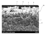
- FIG. 1 is a photograph substituted for a drawing showing the structure of a heat transfer suppressing sheet according to a first embodiment of the present invention.
- FIG. 2 is a photograph substituted for a drawing showing an enlarged part of the heat transfer suppressing sheet according to the first embodiment of the present invention.
- FIG. 3 is a cross-sectional view schematically showing an assembled battery having a heat transfer suppressing sheet according to the first embodiment of the present invention.
- FIG. 4 is a photograph substituted for a drawing showing the structure of a heat transfer suppressing sheet according to the second embodiment of the present invention.
- the present inventors have conducted intensive studies on a heat transfer suppressing sheet that can solve the above problems. As a result, if the heat transfer suppressing sheet has three-dimensionally connected pores, it is possible to obtain excellent heat insulation due to air insulation, and the presence of pores in the sheet improves cushioning properties. Therefore, it has been found that the battery cell has the strength to withstand an increase in compressive stress when it expands, thereby maintaining high heat insulation performance.
- the heat transfer suppressing sheet has a plurality of three-dimensionally connected pores and these are connected to the surface of the heat transfer suppressing sheet, the heat transfer suppressing sheet will become hot and the organic fibers inside It has been found that even when the heat transfer suppressing sheet is decomposed, the decomposed gas is easily released to the outside through the pores, so that the heat transfer suppressing sheet can be prevented from being destroyed.
- FIG. 1 is a photograph substituted for a drawing showing the structure of the heat transfer suppressing sheet according to the first embodiment of the present invention
- FIG. 2 shows a part of the heat transfer suppressing sheet according to the first embodiment of the present invention. This is a photograph substituted for an enlarged drawing.
- FIG. 3 is a cross-sectional view schematically showing an assembled battery having a heat transfer suppressing sheet according to the first embodiment of the present invention.
- the heat transfer suppressing sheet 10 includes inorganic particles 4 and organic fibers 1. Furthermore, the heat transfer suppressing sheet 10 has a plurality of three-dimensionally connected pores 7 between the inorganic particles 4 and the organic fibers 1. Note that the organic fiber 1 has a welded part 5 that covers at least a part of the surface, and at least part of the inorganic particles 4 is welded to the surface of the organic fiber 1 by the welded part 5. Thereby, the surface of the organic fiber 1 is covered with inorganic particles 4.
- the heat transfer suppression sheet 10 can be used so as to be interposed between a plurality of battery cells 20a, 20b, and 20c .
- the assembled battery 100 is configured by storing the plurality of battery cells 20a, 20b, and 20c in a battery case 30 in a state in which they are connected in series or in parallel (the connected state is not shown).
- the battery cells 20a, 20b, and 20c are preferably lithium ion secondary batteries, for example, but are not particularly limited thereto, and can be applied to other secondary batteries as well.
- the heat transfer suppressing sheet 10 according to the first embodiment configured as described above has a plurality of three-dimensionally connected holes 7, the effect of air insulation can be obtained and the insulation performance can be improved. I can do it.
- the heat transfer suppressing sheet 10 according to the present embodiment includes organic fibers 1 having high flexibility, the flexibility of the heat transfer suppressing sheet 10 can be increased, and the organic fibers 1 are easily entangled with each other. Therefore, the effect of improving sheet strength can be obtained.
- the presence of the holes 7 in the heat transfer suppressing sheet 10 improves the cushioning properties of the entire sheet, so when the battery cells 20a, 20b, 20c expand during charging and discharging, the heat transfer suppressing sheet 10 It can absorb the expansion of battery cells. Therefore, destruction of the sheet can be suppressed.
- the holes 7 communicate with the surface of the heat transfer suppressing sheet and open outward. If the holes 7 are configured in this way, when the adjacent battery cells 20a, 20b, 20c undergo thermal runaway, the heat transfer suppressing sheet 10 becomes high temperature and the organic fibers 1 etc. are decomposed. However, the decomposed gas does not stay inside the sheet, but is released to the outside through the holes 7. Therefore, from this point as well, it is possible to obtain the effect of preventing the destruction of the sheet.
- the inorganic particles 4 are prevented from falling off (powder falling). effect can be obtained. Therefore, for example, even if some of the battery cells 20a, 20b, 20c expand and compressive stress or impact is applied to the heat transfer suppressing sheet 10, the effect of retaining the shape can be further enhanced, and the heat transfer It is possible to prevent the heat insulating effect from decreasing due to compressive deformation of the suppression sheet 10.
- the welded portion 5 refers to a portion where the surface of the organic fiber 1 is melted and then solidified again, and is formed in the manufacturing process of the heat transfer suppressing sheet 10, which will be described later.
- the inorganic particles 4 are welded to the surface of the organic fibers 1 by the welding part 5, the apparent fiber diameter of the organic fibers 1 becomes thicker and supports the shape of the heat transfer suppressing sheet 10. , high strength can be obtained.
- the welded portion 5 does not need to completely cover the outer peripheral surface of the organic fiber 1, and there may be a partial region where the welded portion 5 does not exist.
- a binder fiber having a core-sheath structure which will be described later, can be used as the material for the organic fibers 1.
- the core part may partially The organic fiber 1 may be exposed. Even in such a case, the effect of retaining the inorganic particles 4 can be sufficiently obtained.
- the heat transfer suppressing sheet 10 according to the first embodiment preferably contains inorganic fibers.
- inorganic fibers The effects obtained by including inorganic fibers will be explained in the second embodiment below.
- FIG. 4 is a photograph substituted for a drawing showing the structure of a heat transfer suppressing sheet according to the second embodiment of the present invention.
- the same components as those in the first embodiment shown in FIGS. 1 and 2 are denoted by the same reference numerals, and detailed description thereof will be omitted.
- the heat transfer suppressing sheet according to the second embodiment can be used in place of the heat transfer suppressing sheet 10 described in the assembled battery 100 shown in FIG. The sheet will be described below as applied to the assembled battery 100.
- the heat transfer suppressing sheet 40 has inorganic fibers 15. Further, the heat transfer suppressing sheet 40 has the fiber layer 11 formed on at least a portion of a first surface 40a and a second surface (not shown) that are orthogonal to the thickness direction.
- the fibrous layer 11 is formed by welding at least a portion of the plurality of organic fibers 1 to each other by a welding portion, and is formed in a layered manner on the surface (first surface and second surface) of the heat transfer suppressing sheet 40. That is, the fiber layer 11 is a layer formed by gathering ten or more organic fibers 1 on the surface of the heat transfer suppressing sheet 40, and extends in a direction substantially parallel to the surface, for example, in a stripe shape.
- the composite layer is a region including a plurality of organic fibers 1, at least some of which are welded to each other by a welded portion, and inorganic particles 4 welded to the organic fibers 1 by the welded portion.
- the inorganic fibers 15 are included in the base layer 13 that includes the inorganic particles 4 and the organic fibers 1, but they may also be included in the fiber layer 11. In FIG. 4, the inorganic fibers 15 in the fiber layer 11 cannot be distinguished and are therefore not shown.
- the heat transfer suppressing sheet 40 has a fiber bundle 6 formed by welding at least a portion of the plurality of organic fibers 1 to each other by the welding part 5.
- the fiber bundle 6 is formed by intertwining ten or more organic fibers 1 with each other and welding the organic fibers 1 to each other in some parts. It is located.
- the heat transfer suppressing sheet 40 according to the second embodiment configured as described above includes inorganic fibers 15 that are difficult to decompose even at high temperatures. Therefore, for example, when the battery cell 20a undergoes thermal runaway and the heat transfer suppressing sheet 40 disposed adjacent to the battery cell 20a is exposed to high temperature, even if the organic fiber 1 decomposes, the inorganic fiber 15 Since the heat transfer suppressing sheet 40 remains, the shape of the heat transfer suppressing sheet 40 can be maintained reliably. In addition, since the flexible organic fibers 1 are likely to get entangled with the relatively hard inorganic fibers 15, the inorganic fibers 15 and the organic fibers 1 form a three-dimensional skeleton, thereby increasing the strength of the heat transfer suppressing sheet 40. This can be further improved.
- the sheet strength is much higher than when the organic fibers 1 are disposed in a dispersed manner.
- the fibrous layer 11 is not simply disposed on the base layer 13, but is a composite in which a part of the fibrous layer 11 and a part of the inorganic particles 4 are mixed between the fibrous layer 11 and the base layer 13. Since the fiber layer 11 has a layer, the fiber layer 11 is reliably bound to the surface of the heat transfer suppressing sheet 10. Therefore, only the fiber layer 11 does not fall off, and a heat transfer suppressing sheet 40 having high strength can be obtained.
- this fibrous layer 11 when the fibrous layer 11 is formed on the surface of the heat transfer suppressing sheet 40, this fibrous layer 11 can absorb the impact given to the heat transfer suppressing sheet 10. The effect of preventing this can be improved.
- the materials constituting the heat transfer suppressing sheet according to the present embodiment will be described in detail using the heat transfer suppressing sheet 10 as an example.
- the same material as the heat transfer suppressing sheet 10 is used for the heat transfer suppressing sheet 40 as well.
- the organic fibers 1 provide flexibility to the heat transfer suppressing sheet 10, and have the effect of maintaining the strength and shape of the sheet by welding the inorganic particles 4 and other organic fibers 1 to the surface thereof.
- single-component organic fibers can be used as the material for the organic fibers 1 in the heat transfer suppressing sheet 10, it is preferable to use binder fibers with a core-sheath structure.
- a binder fiber having a core-sheath structure has a core portion extending in the longitudinal direction of the fiber and a sheath portion formed to cover the outer peripheral surface of the core portion.
- the core portion is made of a first organic material
- the sheath portion is made of a second organic material
- the melting point of the first organic material is higher than the melting point of the second organic material.
- the core portion corresponds to the organic fiber 1 in the heat transfer suppressing sheet 10 .
- the second organic material constituting the sheath portion is melted and then solidified again, so in the heat transfer suppressing sheet 10, the sheath portion becomes the welded portion 5.
- the core that is, the first organic material constituting the organic fiber 1
- the sheath portion that is, the first organic material that is present on the outer peripheral surface of the organic fiber 1. It is not particularly limited as long as it has a melting point higher than the melting point of organic material No. 2.
- the first organic material includes at least one selected from polyethylene terephthalate, polypropylene, and nylon.
- the content of the organic fibers 1 is preferably 2% by mass or more, more preferably 4% by mass or more based on the total mass of the heat transfer suppressing sheet 10. Furthermore, if the content of the organic fibers 1 becomes too large, the content of the inorganic particles 4 will be relatively reduced, so in order to obtain the desired heat insulation performance, the content of the organic fibers must be It is preferably 10% by mass or less, more preferably 8% by mass or less, based on the total mass of.
- the fiber length of the organic fiber 1 is not particularly limited, but from the viewpoint of ensuring moldability and processability, the average fiber length of the organic fiber is preferably 10 mm or less. On the other hand, from the viewpoint of making the organic fibers 1 function as a skeleton and ensuring the compressive strength of the heat transfer suppressing sheet, the average fiber length of the organic fibers 1 is preferably 0.5 mm or more.
- the welded part 5 is formed by once melting the surface of the organic fiber 1 or the sheath part of the binder fiber having a core-sheath structure by heating and then cooling it. In addition to welding, the organic fibers 1 are also welded together.
- the welded portion 5 includes the second organic material forming the sheath portion.
- the second organic material is not particularly limited as long as it has a melting point lower than that of the first organic material constituting the organic fiber 1.
- the second organic material includes at least one selected from polyethylene terephthalate, polyethylene, polypropylene, and nylon. Note that the melting point of the second organic material is preferably 90°C or higher, more preferably 100°C or higher. Further, the melting point of the second organic material is preferably 150°C or lower, more preferably 130°C or lower.
- the inorganic particles a single inorganic particle may be used, or two or more types of inorganic particles may be used in combination.
- the type of inorganic particles it is preferable to use particles made of at least one inorganic material selected from oxide particles, carbide particles, nitride particles, and inorganic hydrate particles from the viewpoint of heat transfer suppressing effect. , it is more preferable to use oxide particles.
- the shape is not particularly limited, but it is preferable to include at least one selected from nanoparticles, hollow particles, and porous particles, and specifically, silica nanoparticles, metal oxide particles, microporous particles, and hollow particles.
- Inorganic balloons such as silica particles, particles made of a thermally expandable inorganic material, particles made of a hydrous porous material, etc. can also be used.
- the average secondary particle diameter of the inorganic particles is 0.01 ⁇ m or more, they are easily available and can suppress an increase in manufacturing costs. Further, when the thickness is 200 ⁇ m or less, a desired heat insulation effect can be obtained. Therefore, the average secondary particle diameter of the inorganic particles is preferably 0.01 ⁇ m or more and 200 ⁇ m or less, more preferably 0.05 ⁇ m or more and 100 ⁇ m or less.
- the heating element can be cooled in multiple stages, and the endothermic effect can be exerted over a wider temperature range.
- a mixture of large diameter particles and small diameter particles it is preferable to use a mixture of large diameter particles and small diameter particles.
- the other inorganic particles include inorganic particles made of a metal oxide.
- the inorganic particles will be described in more detail, with small-diameter inorganic particles being referred to as first inorganic particles and large-diameter inorganic particles being referred to as second inorganic particles.
- Oxide particles have a high refractive index and have a strong effect of diffusely reflecting light, so when oxide particles are used as the first inorganic particles, radiant heat transfer can be suppressed, particularly in high temperature regions such as abnormal heat generation.
- oxide particles at least one particle selected from silica, titania, zirconia, zircon, barium titanate, zinc oxide, and alumina can be used. That is, among the above-mentioned oxide particles that can be used as inorganic particles, only one type or two or more types of oxide particles may be used.
- silica is a component with high heat insulation properties
- titania is a component with a high refractive index compared to other metal oxides, and is highly effective in diffusely reflecting light and blocking radiant heat in high temperature regions of 500 degrees Celsius or higher. Therefore, it is most preferable to use silica and titania as the oxide particles.
- Average primary particle diameter of oxide particles 0.001 ⁇ m or more and 50 ⁇ m or less
- the average primary particle diameter of the oxide particles is 0.001 ⁇ m or more, it is sufficiently larger than the wavelength of the light that contributes to heating, and in order to diffusely reflect light efficiently, it is difficult to transfer heat in the high temperature region of 500°C or more. The radiant heat transfer within the suppression sheet is suppressed, and the heat insulation properties can be further improved.
- the average primary particle diameter of the oxide particles is 50 ⁇ m or less, the number of contact points between the particles does not increase even when the particles are compressed, and it is difficult to form a path for conductive heat transfer, so conductive heat transfer is particularly dominant. The influence on the heat insulation properties in the normal temperature range can be reduced.
- the average primary particle diameter can be determined by observing the particles with a microscope, comparing them with a standard scale, and taking the average of 10 arbitrary particles.
- nanoparticles refer to nanometer-order particles having a spherical or nearly spherical average primary particle diameter of less than 1 ⁇ m. Because nanoparticles have a low density, they suppress conductive heat transfer, and when nanoparticles are used as the first inorganic particles, the three-dimensionally connected pores 7 become even finer, resulting in excellent heat insulation that suppresses convective heat transfer. You can get sex. For this reason, it is preferable to use nanoparticles because they can suppress the conduction of heat between adjacent nanoparticles during normal use of the battery in the normal temperature range.
- the heat transfer suppressing sheet will be compressed by the expansion caused by thermal runaway of the battery cell, and even if the internal density increases, the heat transfer will be reduced. It is possible to suppress an increase in conductive heat transfer of the suppression sheet. This is thought to be because nanoparticles tend to form fine voids between particles due to the repulsive force caused by static electricity, and because their bulk density is low, the particles are filled so as to provide cushioning properties.
- the material when using nanoparticles as the first inorganic particles, is not particularly limited as long as it meets the above definition of nanoparticles.
- silica nanoparticles in addition to being a highly insulating material, silica nanoparticles have small contact points between particles, so the amount of heat conducted by silica nanoparticles is smaller than when using silica particles with a large particle size.
- commonly available silica nanoparticles have a bulk density of about 0.1 (g/cm 3 ), so for example, battery cells placed on both sides of the heat transfer suppressing sheet may thermally expand, resulting in heat transfer.
- silica nanoparticles As the nanoparticles.
- silica nanoparticles include wet silica, dry silica, and airgel, and silica nanoparticles that are particularly suitable for this embodiment will be described below.
- wet silica particles are aggregated, whereas dry silica particles can be dispersed.
- conductive heat transfer is dominant, so dry silica, which allows particles to be dispersed, provides better heat insulation performance than wet silica. can.
- the heat transfer suppressing sheet according to the present embodiment preferably uses a manufacturing method in which a mixture containing the materials is processed into a sheet shape by a dry method. Therefore, as the inorganic particles, it is preferable to use dry silica, silica airgel, etc., which have low thermal conductivity.
- Average primary particle diameter of nanoparticles 1 nm or more and 100 nm or less
- the average primary particle diameter of the nanoparticles is set to 1 nm or more and 100 nm or less, convective heat transfer and conductive heat transfer within the heat transfer suppressing sheet can be suppressed, especially in the temperature range below 500°C, and the heat insulation property is improved. can be further improved.
- the voids remaining between nanoparticles and the many contact points between particles suppress conductive heat transfer, and the heat insulation properties of the heat transfer suppressing sheet can be maintained. .
- the average primary particle diameter of the nanoparticles is more preferably 2 nm or more, and even more preferably 3 nm or more.
- the average primary particle diameter of the nanoparticles is more preferably 50 nm or less, and even more preferably 10 nm or less.
- Inorganic hydrate particles thermally decompose when they receive heat from a heating element and reach a thermal decomposition start temperature, releasing their own water of crystallization and lowering the temperature of the heating element and its surroundings, a so-called "endothermic action.” Express. Furthermore, after releasing the crystal water, it becomes a porous body and exhibits a heat insulating effect due to its countless air holes.
- Specific examples of inorganic hydrates include aluminum hydroxide (Al(OH) 3 ), magnesium hydroxide (Mg(OH) 2 ), calcium hydroxide (Ca(OH) 2 ), and zinc hydroxide (Zn(OH)).
- aluminum hydroxide has about 35% water of crystallization, and as shown in the following formula, it thermally decomposes to release water of crystallization and exhibits an endothermic action. After releasing the crystal water, it becomes porous alumina (Al 2 O 3 ), which functions as a heat insulator. 2Al(OH) 3 ⁇ Al 2 O 3 +3H 2 O
- the heat transfer suppressing sheet 10 is preferably interposed between, for example, battery cells; however, in battery cells that have undergone thermal runaway, The temperature rises rapidly and continues to rise to around 700°C. Therefore, the inorganic particles are preferably composed of inorganic hydrates whose thermal decomposition initiation temperature is 200° C. or higher.
- the thermal decomposition starting temperatures of the inorganic hydrates listed above are approximately 200°C for aluminum hydroxide, approximately 330°C for magnesium hydroxide, approximately 580°C for calcium hydroxide, approximately 200°C for zinc hydroxide, and approximately 200°C for iron hydroxide.
- the average secondary particle diameter of the inorganic hydrate particles is preferably 0.01 ⁇ m or more and 200 ⁇ m or less, more preferably 0.05 ⁇ m or more and 100 ⁇ m or less.
- thermally expandable inorganic material examples include vermiculite, bentonite, mica, pearlite, and the like.
- Water-containing porous material particles made of water-containing porous material
- water-containing porous material include zeolite, kaolinite, montmorillonite, acid clay, diatomaceous earth, wet silica, dry silica, aerogel, mica, and vermiculite.
- the heat insulating material used in the present invention may contain an inorganic balloon as the first inorganic particles.
- an inorganic balloon When an inorganic balloon is included, convection heat transfer or conductive heat transfer within the heat insulating material can be suppressed in a temperature range of less than 500° C., and the heat insulating properties of the heat insulating material can be further improved.
- the inorganic balloon at least one selected from a shirasu balloon, a silica balloon, a fly ash balloon, a barite balloon, and a glass balloon can be used.
- Inorganic balloon content 60% by mass or less based on the total mass of the insulation material
- the content of the inorganic balloon is preferably 60% by mass or less based on the total mass of the heat insulating material.
- the average particle diameter of the inorganic balloon is preferably 1 ⁇ m or more and 100 ⁇ m or less.
- the second inorganic particles are not particularly limited as long as they are different from the first inorganic particles in material, particle size, etc.
- the second inorganic particles include oxide particles, carbide particles, nitride particles, inorganic hydrate particles, silica nanoparticles, metal oxide particles, inorganic balloons such as microporous particles and hollow silica particles, and thermally expandable inorganic materials. Particles made of a water-containing porous material, particles made of a water-containing porous material, etc. can be used, and the details thereof are as described above.
- nanoparticles have extremely low conductive heat transfer and can maintain excellent heat insulation properties even when compressive stress is applied to the heat transfer suppressing sheet. Furthermore, metal oxide particles such as titania are highly effective in blocking radiant heat. Furthermore, when large-diameter inorganic particles and small-diameter inorganic particles are used, the small-diameter inorganic particles enter the gaps between the large-diameter inorganic particles, resulting in a more dense structure and improving the heat transfer suppression effect. can. Therefore, when nanoparticles, for example, are used as the first inorganic particles, particles made of a metal oxide having a larger diameter than the first inorganic particles are further used as the second inorganic particles to suppress heat transfer. It is preferable to include it in the sheet.
- metal oxides examples include silicon oxide, titanium oxide, aluminum oxide, barium titanate, zinc oxide, zircon, and zirconium oxide.
- titanium oxide titanium oxide (titania) is a component with a high refractive index compared to other metal oxides, and is highly effective in diffusely reflecting light and blocking radiant heat in the high temperature range of 500°C or higher, so titania can be used. Most preferred.
- At least one particle selected from dry silica particles and silica aerogel was used as the first inorganic particle, and the second inorganic particle was selected from titania, zircon, zirconia, silicon carbide, zinc oxide, and alumina.
- the first inorganic particles in order to obtain excellent heat insulation performance within a temperature range of 300°C or less, the first inorganic particles must be present in an amount of 50% by mass or more based on the total mass of the inorganic particles. It is preferably at least 60% by mass, more preferably at least 70% by mass.
- the content of the first inorganic particles is preferably 95% by mass or less, more preferably 90% by mass or less, and even more preferably 80% by mass or less, based on the total mass of the inorganic particles.
- the second inorganic particles are preferably 5% by mass or more, and 10% by mass or more based on the total mass of the inorganic particles. More preferably, it is 20% by mass or more. Further, the second inorganic particles account for preferably 50% by mass or less, more preferably 40% by mass or less, and even more preferably 30% by mass or less, based on the total mass of the inorganic particles.
- the heat transfer suppressing sheet contains second inorganic particles made of a metal oxide, if the average primary particle diameter of the second inorganic particles is 1 ⁇ m or more and 50 ⁇ m or less, efficiency is improved in a high temperature region of 500°C or higher. Radiation heat transfer can be well suppressed.
- the average primary particle diameter of the second inorganic particles is more preferably 5 ⁇ m or more and 30 ⁇ m or less, and most preferably 10 ⁇ m or less.
- the total content of inorganic particles 4 in the heat transfer suppressing sheet 10 is appropriately controlled, the heat insulation properties of the heat transfer suppressing sheet 10 can be sufficiently ensured.
- the total content of the inorganic particles 4 is preferably 60% by mass or more, more preferably 70% by mass or more based on the total mass of the heat transfer suppressing sheet 10. Furthermore, if the total content of inorganic particles 4 becomes too large, the content of organic fibers will be relatively reduced.
- the total content of is preferably 95% by mass or less, more preferably 90% by mass or less based on the total mass of the heat transfer suppressing sheet 10.
- the content of the inorganic particles 4 in the heat transfer suppressing sheet 10 can be calculated, for example, by heating the heat transfer suppressing sheet 10 at 800° C., decomposing the organic components, and then measuring the mass of the remaining portion. can.
- the heat transfer suppressing sheets 10 and 40 according to the first and second embodiments of the present invention include inorganic fibers 15 in addition to the organic fibers 1, welded portions 5, and inorganic particles 4. Inorganic fibers that are preferably contained in the heat transfer suppressing sheet according to the above-described embodiments will be described below.
- inorganic fiber a single inorganic fiber may be used, or two or more types of inorganic fibers may be used in combination.
- inorganic fibers include silica fibers, alumina fibers, alumina silicate fibers, zirconia fibers, carbon fibers, soluble fibers, refractory ceramic fibers, airgel composites, magnesium silicate fibers, alkali earth silicate fibers, potassium titanate fibers, Ceramic fibers such as silicon carbide fibers and potassium titanate whisker fibers, glass fibers such as glass fibers, glass wool, and slag wool, rock wool, basalt fibers, mullite fibers, mineral fibers other than the above, such as wollastonite, etc.
- Examples include natural mineral fibers. These inorganic fibers are preferable in terms of heat resistance, strength, easy availability, and the like. Among inorganic fibers, from the viewpoint of ease of handling, silica-alumina fibers, alumina fibers, silica fibers, rock wool, alkali earth silicate fibers, and glass fibers are particularly preferred.
- the cross-sectional shape of the inorganic fiber is not particularly limited, and examples thereof include a circular cross-section, a flat cross-section, a hollow cross-section, a polygonal cross-section, a core cross-section, and the like.
- irregular cross-section fibers having a hollow cross-section, a flat cross-section, or a polygonal cross-section can be preferably used because the heat insulation properties are slightly improved.
- a preferable lower limit of the average fiber length of the inorganic fibers is 0.1 mm, and a more preferable lower limit is 0.5 mm.
- a preferable upper limit of the average fiber length of the inorganic fibers is 50 mm, and a more preferable upper limit is 10 mm. If the average fiber length of the inorganic fibers is less than 0.1 mm, the inorganic fibers are unlikely to become entangled with each other, and the mechanical strength of the heat transfer suppressing sheet may decrease.
- the inorganic fibers may not be tightly intertwined with each other, or a single inorganic fiber may curl up, which tends to create continuous voids, resulting in poor insulation. This may lead to a decrease in
- a preferable lower limit of the average fiber diameter of the inorganic fibers is 1 ⁇ m, a more preferable lower limit is 2 ⁇ m, and an even more preferable lower limit is 3 ⁇ m.
- a preferable upper limit of the average fiber diameter of the inorganic fibers is 15 ⁇ m, and a more preferable upper limit is 10 ⁇ m. If the average fiber diameter of the inorganic fibers is less than 1 ⁇ m, the mechanical strength of the inorganic fibers themselves may decrease. Further, from the viewpoint of the influence on human health, it is preferable that the average fiber diameter of the inorganic fibers is 3 ⁇ m or more.
- the average fiber diameter of the inorganic fibers is larger than 15 ⁇ m, solid heat transfer using the inorganic fibers as a medium may increase, leading to a decrease in heat insulation properties, and the formability and strength of the heat transfer suppressing sheet may deteriorate. There is a risk of
- the content of the inorganic fibers is preferably 3% by mass or more and 15% by mass or less based on the total mass of the heat transfer suppressing sheet.
- the content of the inorganic fibers is more preferably 5% by mass or more and 10% by mass or less based on the total mass of the heat transfer suppressing sheet. With such a content, the shape retention, pressure resistance, wind pressure resistance, and inorganic particle retention ability of the inorganic fibers are expressed in a well-balanced manner.
- the organic fibers 1 and inorganic fibers intertwine with each other to form a three-dimensional network, which improves the effect of retaining the inorganic particles 4 and other compounded materials described below. This can be further improved.
- the heat transfer suppressing sheet according to the present embodiment can further contain a binder, a coloring agent, and the like, if necessary. All of these are useful for purposes such as reinforcing the heat transfer suppressing sheet and improving formability, and the total amount is preferably 10% by mass or less based on the total mass of the heat transfer suppressing sheet.
- a binder fiber (not shown) having a core-sheath structure, inorganic particles 4, and inorganic fibers 15 are put into a mixer such as a V-type mixer at a predetermined ratio to produce a mixture.
- a mixer such as a V-type mixer
- fibers with a core-sheath structure which have a core made of a first organic material and a sheath made of a second organic material, as the binder fibers.
- the melting point of the first organic material is higher than the melting point of the second organic material.
- the obtained mixture is put into a predetermined mold and pressurized by a press or the like, and the obtained molded body is heated, thereby melting the sheath portion of the binder fibers.
- the second organic material constituting the molten sheath part and the inorganic particles 4 existing around the binder fibers are dissolved in the core part (organic fibers 1 ), and the areas where the binder fibers were in contact with each other are also welded to each other. Thereby, the heat transfer suppressing sheet 40 processed into a sheet shape can be obtained.
- the heat transfer suppressing sheet 10 according to the first embodiment can also be produced in the same manner as the heat transfer suppressing sheet 40 described above, and the use of the inorganic fibers 15 can be arbitrarily selected.
- the intertwined organic fibers 1 exposed on the surface are heated and formed as the fiber layer 11 on the surface of the heat transfer suppressing sheet 40.
- the fiber layer 11 obtained in this way has the effect of improving the strength of the heat transfer suppressing sheet 40 and mitigating the impact on the surface of the heat transfer suppressing sheet 40.
- the heat transfer suppressing sheets 10 and 40 according to the first and second embodiments described above are preferably manufactured by a dry method.
- a dry method inorganic particles 4 suitable for the dry method are used, and a solvent such as water, which is required when molding by the wet method, is not added to the mixture.
- a small amount of solvent such as water is added within the range of the dry method. It can also be added. For example, by adding a small amount of a solvent such as water to the mixture, scattering of inorganic particles during production can be suppressed.
- a binder fiber having a core-sheath structure is used as a material, and the melting point of the first organic material constituting the core is higher than the melting point of the second organic material constituting the sheath.
- the sheath can be melted leaving the core.
- the outer circumferential surface of the core (organic fiber 1) is covered with the second organic material containing the inorganic particles 4, so that the inorganic particles 4 can be retained.
- the organic fiber 1 to which the inorganic particles 4 are welded has an apparently large fiber diameter, and therefore has higher strength than the strength of the organic fiber 1 alone.
- the binder fibers are present in the mixture in irregular directions, the organic fibers 1 are welded to each other in areas where the binder fibers are in contact with each other, forming a three-dimensional skeleton. As a result, the shape of the entire heat transfer suppressing sheet can be maintained with even higher strength.
- the core can be easily separated.
- the temperature can be set to melt the sheath.
- the obtained heat transfer suppressing sheet has organic fibers 1 welded to each other on both the surface side and the center side to form a skeleton that maintains the strength of the sheet, and contains inorganic particles 4 on the surface of the organic fibers 1. It has an ideal structure in which the welded portion 5 is formed. Therefore, it is preferable to use binder fibers having a core-sheath structure as described above as the material for the heat transfer suppressing sheet.
- an adhesive such as hot melt powder may be included in the mixture as a raw material for the heat transfer suppressing sheet.
- the skeleton formed by the organic fibers 1 can be sufficiently fixed, and the holding power of the inorganic particles 4 can be improved to prevent powder falling. This can be further suppressed.
- the heat transfer suppressing sheet manufactured by the manufacturing method according to the present embodiment has an even stronger skeleton, and even when a pressing force or impact is applied to the heat transfer suppressing sheet, its shape remains unchanged. can be maintained, powder falling can be suppressed, and excellent heat insulation performance can be maintained.
- the surface of the heat transfer suppressing sheet may be covered with a film or the like.
- Polymer films include polyimide, polycarbonate, PET, p-phenylene sulfide, polyetherimide, crosslinked polyethylene, flame-retardant chloroprene rubber, polyvinyldenfluoride, hard vinyl chloride, polybutylene terephthalate, PTFE, PFA, FEP, ETFE, Examples include films made of rigid PCV, flame-retardant PET, polystyrene, polyethersulfone, polyamideimide, polyacrylonitrile, polyethylene, polypropylene, polyamide, and the like.
- the method of covering the surface of the heat transfer suppressing sheet with a film is not particularly limited, and methods include pasting with adhesive, wrapping the heat transfer suppressing sheet with a film, and wrapping the heat transfer suppressing sheet in a bag-like film. Examples include a method of accommodating.
- binder fibers and heating conditions that are preferably used in the method for manufacturing a heat transfer suppressing sheet according to the present embodiment will be described.
- ⁇ Binder fiber> when using a binder fiber with a core-sheath structure, if the melting point of the first organic material constituting the core is higher than the melting point of the second organic material constituting the sheath.
- the first organic material serving as the core at least one selected from polyethylene terephthalate, polypropylene, and nylon can be selected.
- the second organic material that becomes the sheath at least one selected from polyethylene terephthalate, polyethylene, polypropylene, and nylon can be selected.
- the melting point of the first organic material constituting the core is sufficiently higher than the melting point of the second organic material constituting the sheath, the setting latitude for the heating temperature in the heating process can be expanded, and It is possible to more easily set the temperature to obtain a desired structure.
- the melting point of the first organic material is preferably 60°C or more higher than the melting point of the second organic material, more preferably 70°C or more higher, and even more preferably 80°C or more higher.
- binder fibers having a core-sheath structure as described above are generally commercially available, and the materials constituting the core portion and the sheath portion may be the same or different from each other.
- binder fibers in which the core and sheath are made of the same material and have different melting points include those in which the core and sheath are made of polyethylene terephthalate, polypropylene, nylon, etc. It will be done.
- binder fibers in which the core and sheath parts are made of different materials include those in which the core part is made of polyethylene terephthalate and the sheath part is made of polyethylene, and those in which the core part is made of polypropylene and the sheath part is made of polyethylene. Can be mentioned.
- the melting point of the second organic material constituting the sheath of the binder fibers refers to the melting temperature at which the second organic material begins to melt and deform. Judging to be a species.
- the melting point of the sheath portion of the binder fiber can be measured, for example, by the following method. A binder fiber to be measured is placed in contact with a glass fiber having a higher melting point, heated from room temperature to 200° C. at a heating rate of 5° C./min, and then cooled to room temperature.
- the second organic It can be determined that the melting point of the material is 200°C or lower.
- the sheath portion is constructed by varying the heating temperature and observing the fused state of the binder fibers and glass fibers after cooling by the above method, or the cross-sectional shape of the binder fibers. The melting point of the second organic material can be determined.
- Binder fiber content In this embodiment, when using binder fibers with a core-sheath structure as the material, if the content of the binder fibers in the mixture is appropriately controlled, the reinforcing effect of the skeleton in the resulting heat transfer suppressing sheet can be sufficiently enhanced. Obtainable.
- the binder fiber content is preferably 5% by mass or more, more preferably 10% by mass or more based on the total mass of the mixture.
- the content of binder fiber should be adjusted based on the total mass of the mixture. It is preferably 25% by mass or less, more preferably 20% by mass or less.
- hot melt powder in addition to the binder fibers and inorganic particles 4 described above, hot melt powder may be included in the mixture.
- the hot melt powder is a powder that contains, for example, a third organic material different from the first organic material and the second organic material, and has the property of being melted by heating.
- the hot melt powder is melted, and then when it is cooled, it hardens while containing the surrounding inorganic particles 4. Therefore, falling off of the inorganic particles 4 from the heat transfer suppressing sheet can be further suppressed.
- Hot melt powders include those having various melting points, but a hot melt powder having an appropriate melting point may be selected in consideration of the melting points of the core and sheath portions of the binder fibers used. Specifically, if the third organic material that is a component of the hot melt powder has a melting point lower than that of the first organic material that makes up the organic fiber, the third organic material that is a component of the hot melt powder can be used to leave the core portion and the sheath portion and The heating temperature for melting the hot melt powder can be set. For example, if the melting point of the hot melt powder is lower than the melting point of the sheath, the heating temperature during manufacturing can be set between the melting point of the core and the melting point of the sheath, making it easier to heat the powder. can be set.
- the type of hot melt powder to be used can also be selected so that the melting point of the hot melt powder is between the melting point of the core and the melting point of the sheath.
- hot melt powder having such a melting point when used, when the sheath and the hot melt powder are both melted and then cooled and hardened, the organic fiber (core) 1 and the molten sheath around it first melt. , and the hot melt powder present in the gaps between the inorganic particles 4 is cured. As a result, the position of the organic fiber 1 can be fixed, and then the molten sheath portion is welded to the organic fiber, making it easier to form a three-dimensional skeleton. Therefore, the strength of the entire sheet can be further improved.
- the melting point of the third organic material constituting the hot melt powder is sufficiently lower than the melting point of the first organic material constituting the core, the setting latitude for the heating temperature in the heating process can be expanded, It is possible to more easily set the temperature to obtain a desired structure.
- the melting point of the first organic material is preferably 60°C or more higher than the melting point of the third organic material, more preferably 70°C or more higher, and even more preferably 80°C or more higher.
- the melting point of the hot melt powder (third organic material) is preferably 80°C or higher, more preferably 90°C or higher. Further, the melting point of the hot melt powder (third organic material) is preferably 180°C or lower, more preferably 150°C or lower.
- Components constituting the hot melt powder include polyethylene, polyester, polyamide, ethylene vinyl acetate, and the like.
- the content of the hot melt powder is preferably 0.5% by mass or more, more preferably 1% by mass or more based on the total mass of the mixture.
- the content of hot melt powder is increased, the content of inorganic particles 4 etc. is relatively reduced, so in order to obtain the desired heat insulation performance, the content of hot melt powder must be adjusted to the total mass of the mixture. It is preferably 5% by mass or less, more preferably 4% by mass or less.
- the process of processing the mixture into a sheet shape includes a process of pressurizing the mixture and a process of heating the mixture.
- the heating temperature in the heating step is higher than the melting point of the second organic material forming the sheath, and the heating temperature is higher than the melting point of the second organic material forming the core.
- the temperature is preferably lower than the melting point of the organic material No. 1.
- the heating temperature in the heating step is preferably set to be 10° C. or more higher than the melting point of the second organic material forming the sheath, and more preferably 20° C. or more higher.
- the heating temperature is preferably set at least 10°C lower than the melting point of the first organic material constituting the core, and more preferably set at least 20°C lower.
- the heating time is not particularly limited, but it is preferable to set the heating time so that the sheath can be sufficiently melted. For example, it can be set to 3 minutes or more and 15 minutes or less.
- the heating temperature in the heating step is the melting point of the second organic material that makes up the sheath and the melting point of the third organic material that makes up the hot melt powder. It is preferable to set the temperature at least 10°C higher than whichever is higher, and more preferably set it at least 20°C higher. On the other hand, the heating temperature is preferably set at least 10°C lower than the melting point of the first organic material constituting the core, and more preferably set at least 20°C lower. By setting the heating temperature to such a temperature, a strong skeleton can be formed, the strength of the sheet can be further improved, and the inorganic particles 4 can be prevented from falling off by the welded parts 5 and the like. .
- the thickness of the heat transfer suppressing sheet according to this embodiment is not particularly limited, it is preferably 0.05 mm or more and 10 mm or less. When the thickness is 0.05 mm or more, sufficient compressive strength can be obtained. On the other hand, when the thickness is 10 mm or less, good heat insulation properties of the heat transfer suppressing sheet can be obtained.
- FIG. 3 An example of an assembled battery to which the heat transfer suppressing sheet 10 according to the embodiment of the present invention is applied is as illustrated in FIG. 3 above.
- the configuration and effects of the assembled battery will be specifically explained using FIG. 3.
- the heat transfer suppressing sheet 10 shown in FIG. 3 can be replaced with the heat transfer suppressing sheet 40, and can also be replaced with other heat transfer suppressing sheets within the scope of the present invention.
- the assembled battery 100 includes a plurality of battery cells 20a, 20b, 20c and a heat transfer suppression sheet according to the present embodiment, and the plurality of battery cells are connected in series or in parallel.
- the heat transfer suppressing sheet 10 according to the present embodiment is interposed between a battery cell 20a and a battery cell 20b, and between a battery cell 20b and a battery cell 20c.
- the battery cells 20a, 20b, 20c and the heat transfer suppression sheet 10 are housed in a battery case 30. Note that the heat transfer suppressing sheet 10 is as described above.
- the heat transfer suppressing sheet 10 having a heat transfer suppressing effect exists between it and the battery cell 20b. , it is possible to suppress the propagation of heat to the battery cell 20b. Moreover, since the heat transfer suppressing sheet 10 according to the present embodiment has high compressive strength, it is possible to suppress thermal expansion of the battery cells 20a, 20b, and 20c even during charging and discharging of these battery cells. Therefore, the distance between the battery cells can be ensured, excellent heat insulation performance can be maintained, and thermal runaway of the battery cells can be prevented. Moreover, since it has the effect of suppressing powder falling, it can be easily handled.
- the assembled battery 100 of this embodiment is not limited to the assembled battery illustrated in FIG. 3.
- the heat transfer suppressing sheet 10 is applied not only between the battery cells 20a and 20b and between the battery cells 20b and 20c, but also between the battery cells 20a, 20b, 20c and the battery case 30. It may be arranged or attached to the inner surface of the battery case 30.
- the assembled battery 100 configured in this way, when a certain battery cell ignites, it is possible to suppress the flame from spreading to the outside of the battery case 30.
- the assembled battery 100 according to this embodiment is used in an electric vehicle (EV) or the like, and may be placed under a passenger's floor. In this case, even if the battery cell catches fire, the safety of the passenger can be ensured.
- the heat transfer suppressing sheet 10 can be placed not only between each battery cell but also between the battery cells 20a, 20b, 20c and the battery case 30, a new flame retardant material etc. can be prepared. There is no need to do so, and the assembled battery 100 can be easily configured at low cost and safe.
- the heat transfer suppressing sheet 10 according to the present embodiment can be manufactured into various shapes depending on the manufacturing method. Therefore, it is not affected by the shapes of the battery cells 20a, 20b, 20c and the battery case 30, and can be adapted to any shape. Specifically, it can be applied to cylindrical batteries, flat batteries, etc. in addition to prismatic batteries.
Landscapes
- Engineering & Computer Science (AREA)
- General Chemical & Material Sciences (AREA)
- Manufacturing & Machinery (AREA)
- Chemical & Material Sciences (AREA)
- Chemical Kinetics & Catalysis (AREA)
- Electrochemistry (AREA)
- General Engineering & Computer Science (AREA)
- Physics & Mathematics (AREA)
- Mechanical Engineering (AREA)
- Algebra (AREA)
- General Physics & Mathematics (AREA)
- Mathematical Analysis (AREA)
- Mathematical Optimization (AREA)
- Pure & Applied Mathematics (AREA)
- Secondary Cells (AREA)
- Thermal Insulation (AREA)
- Laminated Bodies (AREA)
- Cell Separators (AREA)
Abstract
L'invention concerne : une feuille de commande de transmission de chaleur qui, même si une contrainte de compression appliquée à la feuille de commande de transmission de chaleur est augmentée, peut maintenir des propriétés d'isolation thermique et empêcher la rupture de la feuille lorsqu'une cellule de batterie adjacente subit un emballement thermique ; et un bloc-batterie comprenant la feuille de commande de transmission de chaleur. Une feuille de commande de transmission de chaleur (10) comprend des particules inorganiques (4) et des particules organiques (1), et comprend également une pluralité de vides (7) qui sont liés de manière tridimensionnelle.
Applications Claiming Priority (2)
| Application Number | Priority Date | Filing Date | Title |
|---|---|---|---|
| JP2022086809A JP7364742B1 (ja) | 2022-05-27 | 2022-05-27 | 熱伝達抑制シート及び組電池 |
| JP2022-086809 | 2022-05-27 |
Publications (1)
| Publication Number | Publication Date |
|---|---|
| WO2023229044A1 true WO2023229044A1 (fr) | 2023-11-30 |
Family
ID=88328418
Family Applications (1)
| Application Number | Title | Priority Date | Filing Date |
|---|---|---|---|
| PCT/JP2023/019812 WO2023229044A1 (fr) | 2022-05-27 | 2023-05-26 | Feuille de commande de transmission de chaleur et bloc-batterie |
Country Status (2)
| Country | Link |
|---|---|
| JP (2) | JP7364742B1 (fr) |
| WO (1) | WO2023229044A1 (fr) |
Citations (2)
| Publication number | Priority date | Publication date | Assignee | Title |
|---|---|---|---|---|
| JP2012081701A (ja) * | 2010-10-14 | 2012-04-26 | Nichias Corp | 断熱材および断熱材の製造方法 |
| JP2021140968A (ja) * | 2020-03-06 | 2021-09-16 | ニチアス株式会社 | 電池用断熱材及び電池 |
-
2022
- 2022-05-27 JP JP2022086809A patent/JP7364742B1/ja active Active
-
2023
- 2023-05-26 WO PCT/JP2023/019812 patent/WO2023229044A1/fr unknown
- 2023-09-29 JP JP2023170327A patent/JP2023174628A/ja active Pending
Patent Citations (2)
| Publication number | Priority date | Publication date | Assignee | Title |
|---|---|---|---|---|
| JP2012081701A (ja) * | 2010-10-14 | 2012-04-26 | Nichias Corp | 断熱材および断熱材の製造方法 |
| JP2021140968A (ja) * | 2020-03-06 | 2021-09-16 | ニチアス株式会社 | 電池用断熱材及び電池 |
Also Published As
| Publication number | Publication date |
|---|---|
| JP2023174628A (ja) | 2023-12-07 |
| JP2023174129A (ja) | 2023-12-07 |
| JP7364742B1 (ja) | 2023-10-18 |
Similar Documents
| Publication | Publication Date | Title |
|---|---|---|
| WO2023127904A1 (fr) | Feuille de suppression de transfert de chaleur et bloc-batterie | |
| JP7364742B1 (ja) | 熱伝達抑制シート及び組電池 | |
| WO2023229042A1 (fr) | Feuille de suppression de transfert de chaleur et bloc-batterie | |
| WO2023229047A1 (fr) | Feuille de suppression de transfert de chaleur et bloc-batterie | |
| JP7414888B2 (ja) | 熱伝達抑制シート及び組電池 | |
| WO2023229046A1 (fr) | Feuille de suppression de transfert de chaleur et bloc-batterie | |
| JP7364722B2 (ja) | 熱伝達抑制シートの製造方法、熱伝達抑制シート及び組電池 | |
| JP7436582B1 (ja) | 熱伝達抑制シート及び組電池 | |
| WO2023171818A1 (fr) | Procédé de production de feuille de suppression de transfert de chaleur, feuille de suppression de transfert de chaleur et bloc-batterie | |
| WO2024101455A1 (fr) | Feuille de suppression de transfert de chaleur et bloc-batterie | |
| JP7364739B2 (ja) | 熱伝達抑制シート及び組電池 | |
| WO2024004968A1 (fr) | Feuille de suppression de transfert de chaleur et bloc-batterie | |
| WO2023120545A1 (fr) | Feuille isolante et bloc-batterie | |
| JP2024070502A (ja) | 熱伝達抑制シート及び組電池 | |
| JP2024070861A (ja) | 熱伝達抑制シート及び組電池 | |
| WO2023127905A1 (fr) | Feuille de suppression de transfert thermique, et ensemble batterie | |
| WO2023182384A1 (fr) | Structure ignifuge, son procédé de fabrication et module de batterie | |
| WO2023120340A1 (fr) | Feuille de suppresion de transfert de chaleur et bloc-batterie | |
| JP2023170065A (ja) | 防炎シート及びその製造方法、並びに電池モジュール | |
| JP2023092423A (ja) | 断熱シート及び組電池 | |
| CN116266653A (zh) | 热传递抑制片及其制造方法、以及电池组 |
Legal Events
| Date | Code | Title | Description |
|---|---|---|---|
| 121 | Ep: the epo has been informed by wipo that ep was designated in this application |
Ref document number: 23811916 Country of ref document: EP Kind code of ref document: A1 |