WO2023223750A1 - 表示装置 - Google Patents
表示装置 Download PDFInfo
- Publication number
- WO2023223750A1 WO2023223750A1 PCT/JP2023/015469 JP2023015469W WO2023223750A1 WO 2023223750 A1 WO2023223750 A1 WO 2023223750A1 JP 2023015469 W JP2023015469 W JP 2023015469W WO 2023223750 A1 WO2023223750 A1 WO 2023223750A1
- Authority
- WO
- WIPO (PCT)
- Prior art keywords
- virtual object
- user
- guide image
- display
- glasses
- Prior art date
- Legal status (The legal status is an assumption and is not a legal conclusion. Google has not performed a legal analysis and makes no representation as to the accuracy of the status listed.)
- Ceased
Links
Images


Classifications
-
- G—PHYSICS
- G06—COMPUTING OR CALCULATING; COUNTING
- G06F—ELECTRIC DIGITAL DATA PROCESSING
- G06F3/00—Input arrangements for transferring data to be processed into a form capable of being handled by the computer; Output arrangements for transferring data from processing unit to output unit, e.g. interface arrangements
- G06F3/01—Input arrangements or combined input and output arrangements for interaction between user and computer
- G06F3/048—Interaction techniques based on graphical user interfaces [GUI]
- G06F3/0481—Interaction techniques based on graphical user interfaces [GUI] based on specific properties of the displayed interaction object or a metaphor-based environment, e.g. interaction with desktop elements like windows or icons, or assisted by a cursor's changing behaviour or appearance
-
- G—PHYSICS
- G06—COMPUTING OR CALCULATING; COUNTING
- G06F—ELECTRIC DIGITAL DATA PROCESSING
- G06F3/00—Input arrangements for transferring data to be processed into a form capable of being handled by the computer; Output arrangements for transferring data from processing unit to output unit, e.g. interface arrangements
- G06F3/16—Sound input; Sound output
-
- G—PHYSICS
- G06—COMPUTING OR CALCULATING; COUNTING
- G06T—IMAGE DATA PROCESSING OR GENERATION, IN GENERAL
- G06T19/00—Manipulating three-dimensional [3D] models or images for computer graphics
-
- G—PHYSICS
- G10—MUSICAL INSTRUMENTS; ACOUSTICS
- G10L—SPEECH ANALYSIS TECHNIQUES OR SPEECH SYNTHESIS; SPEECH RECOGNITION; SPEECH OR VOICE PROCESSING TECHNIQUES; SPEECH OR AUDIO CODING OR DECODING
- G10L15/00—Speech recognition
Definitions
- the present invention relates to a display device.
- a display device that provides a virtual space to a user displays a portion of the virtual space that is visible from the user's viewpoint.
- Patent Document 1 discloses a program that displays a controller object indicating the position of a game controller in real space in virtual space. This program displays a direction guide object pointing in the direction of the controller object in the virtual space when the controller object is not within the imaging range of the virtual stereo camera.
- the conventional technology has a problem in that the visibility of the virtual space decreases.
- An object of the present disclosure is to provide a display device that guides a user's line of sight in the direction of a virtual object that exists outside the display area of the display device while suppressing a decrease in the visibility of a virtual space.
- a display device is a display device that displays a part of an augmented reality space or a mixed reality space in which a virtual object placed in a virtual space is superimposed on a real space in a display area. , an image that generates a guide image that guides the user's line of sight to the position of the virtual object based on the position of the virtual object arranged in the virtual space when the virtual object is not displayed in the display area;
- the display device includes a generation unit and a display control unit that displays the guide image at a position adjacent to an outer edge of the display area.
- the present invention compared to the prior art, it is possible to guide the user's line of sight in the direction of a virtual object that exists outside the display area of the display device without reducing the visibility of the virtual space. .
- FIG. 1 is a block diagram showing the overall configuration of an information processing system 1.
- FIG. FIG. 3 is a schematic diagram of a virtual object VO and a guide image GP that guides the position of the virtual object VO.
- FIG. 3 is a diagram showing mutually orthogonal X-axis, Y-axis, and Z-axis assumed in virtual space.
- FIG. 2 is a block diagram showing a configuration example of a management server 50.
- FIG. Flowchart showing the contents of display processing. Flowchart showing the contents of display processing.
- FIG. 3 is a schematic diagram of a virtual object VO and a guide image GP that guides the user's line of sight to the position of the virtual object VO.
- An example of the appearance of the guide image GP An example of the appearance of the guide image GP.
- FIG. 1 is a block diagram showing the overall configuration of the information processing system 1.
- the information processing system 1 includes XR glasses 10-1, 10-2, ... 10-k, ... 10-j, and a management server that manages data related to augmented reality space or mixed reality space.
- 50. j is any integer greater than or equal to 1.
- k is any integer from 1 to j.
- the XR glasses 10-1, 10-2, . . . 10-k, . . . 10-j have the same configuration.
- the information processing system 1 may include XR glasses with different configurations.
- the management server 50 and the XR glasses 10-k are communicably connected to each other via the communication network NET.
- user U[k] uses XR glasses 10-k.
- the XR glasses 10-k are so-called transmissive display glasses, and are an example of a display device that displays an augmented reality space or a mixed reality space that includes virtual objects.
- Augmented reality space means a virtual space in which virtual objects can be displayed superimposed on real objects in real space.
- Mixed reality space refers to a virtual space in which real objects in real space and virtual objects are related to each other.
- virtual objects are simply displayed superimposed on real objects.
- the interaction between virtual objects and real objects can be expressed by using a physical model of the virtual object. For example, when a user throws a virtual ball object at a wall, which is a real object, the ball bounces off the wall.
- the user U[k] views the virtual object while viewing the real-world view through the XR glasses 10-k.
- a virtual object is arranged in virtual space in correspondence with a position in real space.
- the user U[k] recognizes an augmented reality space or a mixed reality space that is a combination of a real space and a virtual space.
- FIG. 2 shows a virtual object VO existing in an augmented reality space or a mixed reality space, which the user U[k] recognizes by using the XR glasses 10-k, and the user's line of sight toward the position of the virtual object VO.
- It is a schematic diagram of a guide image GP for guiding.
- the display area AR of the XR glasses 10-k the area visible to the user U[k] through the XR glasses 10-k will be referred to as the display area AR of the XR glasses 10-k.
- the display area AR of the XR glasses 10-k is a rectangle with four vertices at points A to D.
- the virtual object VO is located outside the range of the display area AR, and that the center of gravity F of the virtual object VO is located in the direction of the vertex B when viewed from the center E of the display area AR.
- the guide image GP consists of a first rectangle P1 with vertex B as an end point and a part of side AB as a long side, and a first rectangle P1 with vertex B as an end point and a part of side BD as a long side. It has an L-shaped shape including two rectangles P2.
- FIG. 3 is a block diagram showing an example of the configuration of the XR glasses 10-k.
- the XR glasses 10-k include a processing device 11, a storage device 12, an imaging device 13, a sound collection device 14, a detection device 15, a communication device 16, and a projection device 17.
- Each element included in the XR glasses 10-k is interconnected by one or more buses for communicating information.
- the processing device 11 is a processor that controls the entire XR glasses 10-k.
- the processing device 11 is configured using, for example, a single chip or a plurality of chips. Further, the processing device 11 is configured using, for example, a central processing unit (CPU) including an interface with a peripheral device, an arithmetic unit, a register, and the like. Note that some or all of the functions of the processing device 11 may be realized by hardware such as DSP (Digital Signal Processor), ASIC (Application Specific Integrated Circuit), PLD (Programmable Logic Device), FPGA (Field Programmable Gate Array), etc. You may.
- the processing device 11 executes various processes in parallel or sequentially.
- the storage device 12 is a recording medium that can be read and written by the processing device 11. Furthermore, the storage device 12 stores a plurality of programs including the control program PR1 executed by the processing device 11. The storage device 12 functions as a work area for the processing device 11. The storage device 12 also stores data used by an image generation unit 111 (described later) to render a virtual object VO, a guide image GP, and a virtual space in which the virtual object VO exists.
- the imaging device 13 outputs a captured image obtained by capturing an image of the outside world. Further, the imaging device 13 includes, for example, a lens, an imaging element, an amplifier, and an AD converter.
- the light collected through the lens is converted into an image signal, which is an analog signal, by an image sensor.
- the amplifier amplifies the imaging signal and outputs it to the AD converter.
- the AD converter converts the amplified imaging signal, which is an analog signal, into imaging information, which is a digital signal.
- the converted imaging information is output to the processing device 11.
- the captured image output to the processing device 11 is output to the management server 50 via the communication device 16.
- the shape of the XR glasses 10-k is similar to that of general eyeglasses.
- the XR glasses 10-k have a left lens, a right lens, and a frame that supports the left lens and the right lens.
- the frame has a bridge provided between the left lens and the right lens, and a pair of temples spanning the left and right ears of a person.
- the imaging device 13 is provided on the bridge. Therefore, the imaging device 13 images the outside world in the direction in which the face of the user U[k] is facing.
- the sound collection device 14 is a microphone that includes a sound collection section that collects sounds around the XR glasses 10-k and converts the collected sounds into electrical signals.
- the sound collection section may have any structure as long as it is configured to collect sound, and for example, a windproof structure is applicable.
- the sound collection device 14 collects the voice of the user U[k] as the surrounding sound.
- the detection device 15 detects the state of the XR glasses 10-k.
- the detection device 15 includes, for example, an inertial sensor such as an acceleration sensor that detects acceleration and a gyro sensor that detects angular acceleration, a geomagnetic sensor that detects orientation, and a GPS device that detects the position of the XR glasses 10-k in real space. This applies to positioning devices such as The acceleration sensor detects acceleration on orthogonal X, Y, and Z axes.
- the gyro sensor detects angular acceleration with the X-axis, Y-axis, and Z-axis as central axes of rotation.
- the detection device 15 can generate posture information regarding the posture of the XR glasses 10-k based on the output information of the gyro sensor.
- the motion information includes acceleration information indicating the acceleration of each of the three axes and angular acceleration information indicating the angular acceleration of the three axes.
- the detection device 15 also provides posture information regarding the posture of the XR glasses 10-k, movement information regarding the movement of the XR glasses 10-k, azimuth information regarding the orientation of the XR glasses 10-k, and position information regarding the position of the XR glasses 10-k.
- the information is output to the processing device 11.
- the communication device 16 is hardware as a transmitting/receiving device for communicating with other devices. Further, the communication device 16 is also called, for example, a network device, a network controller, a network card, a communication module, or the like. Furthermore, the communication device 16 may include a wireless communication interface. Examples of connectors and interface circuits for wired connections include products compliant with wired LAN, IEEE1394, and USB. Furthermore, examples of wireless communication interfaces include products compliant with wireless LAN, Bluetooth (registered trademark), and the like.
- the projection device 17 is a device that displays images.
- the projection device 17 displays various images under the control of the processing device 11.
- the left temple of the XR glasses 10-k is provided with a display panel for the left eye and an optical member that guides light emitted from the display panel for the left eye to a lens.
- the half mirror provided on the left lens transmits external light and guides it to the left eye, and also reflects the light guided by the optical member and makes it enter the left eye.
- the right temple and right lens are similarly configured.
- the projection device 17 includes a left lens, a right lens, a display panel for the left eye, a display panel for the right eye, an optical member for the left eye, and an optical member for the right eye.
- the user U[k] can observe the image displayed on the display panel in a see-through state superimposed on the outside world. Furthermore, the XR glasses 10-k display the left-eye image on the left-eye display panel and the right-eye image on the right-eye display panel among the binocular images with parallax. Therefore, the XR glasses 10-k allow the user U[k] to perceive the displayed image as if it had depth and stereoscopic effect.
- the processing device 11 reads the control program PR1 from the storage device 12 and executes the read control program PR1, thereby controlling the image generation section 111, the display control section 112, the detection section 113, and the voice recognition section. 114.
- the image generation unit 111 generates an image showing the virtual space in which the virtual object VO is placed. Furthermore, when the virtual object VO is not displayed in the display area AR, the image generation unit 111 guides the user's line of sight to the position of the virtual object VO based on the position of the virtual object VO placed in the virtual space. A guide image GP is generated. Each of the image showing the virtual object VO and the guide image GP may be a two-dimensional image or a three-dimensional image. The image generation unit 111 generates a guide image GP in response to user U[k]'s input to the XR glasses 10-k.
- the display control unit 112 causes the projection device 17 to display an image showing the virtual space in which the virtual object VO is placed. As a result, a portion of the augmented reality space or mixed reality space, in which the real space and the virtual space displayed by the display control unit 112 are superimposed, is displayed in the display area of the XR glasses 10-k.
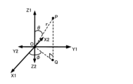
- FIG. 4 is a diagram showing the mutually orthogonal X-axis, Y-axis, and Z-axis assumed in the virtual space.
- the X-axis, Y-axis, and Z-axis are common to all the figures illustrated in the following description.
- one direction along the X axis viewed from an arbitrary point is referred to as the X1 direction
- a direction opposite to the X1 direction is referred to as the X2 direction.
- the X-axis direction is a direction including both the X1 direction and the X2 direction.
- mutually opposite directions along the Y-axis from an arbitrary point are expressed as the Y1 direction and the Y2 direction.
- the Y-axis direction includes both the Y1 direction and the Y2 direction. Further, mutually opposite directions along the Z-axis from an arbitrary point are expressed as Z1 direction and Z2 direction.
- the Z-axis direction includes both the Z1 direction and the Z2 direction.
- the XR glasses 10-k are located at the origin O. Further, the depth direction of the XR glasses 10-k is defined as the Y1 direction, and the near side direction as seen from the user U[k] facing the XR glasses 10-k is defined as the Y2 direction. Further, the right hand direction as viewed from the user U[k] facing the XR glasses 10-k is defined as the X1 direction, and the left hand direction is defined as the X2 direction. Furthermore, when viewed from the user U[k] facing the XR glasses 10-k, the upward direction is defined as the Z1 direction, and the downward direction is defined as the Z2 direction.
- an r ⁇ coordinate system which is a three-dimensional polar coordinate system, is assumed to be superimposed on the XYZ coordinate system.
- the position of any point P is indicated by a distance r from the origin O and two angular parameters ⁇ and ⁇ .
- ⁇ is the angle between the Z1 direction and the straight line OP, and satisfies 0 ⁇ . If the foot of the perpendicular drawn from point P to the XY plane is point Q, ⁇ is the angle between the X1 direction and straight line OQ, and 0 ⁇ 2 ⁇ .
- FIG. 5 shows an example of the position of the display area AR in the r ⁇ coordinate system.
- the display area AR is a part of a spherical surface centered at the origin O and having a radius r1 , and has four vertices, which are vertices A to D.
- a region where 0 ⁇ 1 and ⁇ 2 ⁇ 2 ⁇ is defined as a region ⁇ .
- the region where 0 ⁇ 1 and ⁇ 1 ⁇ 2 is defined as region ⁇ .
- a region where 0 ⁇ ⁇ 1 and 0 ⁇ ⁇ 1 is defined as a region ⁇ .
- the region where ⁇ 1 ⁇ 2 and ⁇ 2 ⁇ 2 ⁇ is defined as a region ⁇ .
- the region where ⁇ 1 ⁇ 2 and ⁇ 1 ⁇ 2 is defined as a region ⁇ .
- the region where ⁇ 1 ⁇ 2 and 0 ⁇ 1 is defined as region ⁇ .
- the region where ⁇ 2 ⁇ and ⁇ 2 ⁇ 2 ⁇ is defined as a region ⁇ .
- the region where ⁇ 2 ⁇ and ⁇ 1 ⁇ 2 is defined as a region ⁇ .
- the region where ⁇ 2 ⁇ and ⁇ 1 is defined as a region ⁇ .
- the region where ⁇ 2 ⁇ and 0 ⁇ 1 is defined as a region ⁇ .
- the display control unit 112 displays the guide image GP at a position adjacent to the outer edge of the display area AR of the XR glasses 10-k.
- 6A and 6B are examples of display positions of the guide image GP. The operation of the display control unit 112 will be described below with reference to FIG. 2 described above in addition to FIGS. 6A and 6B.
- the display control unit 112 displays a guide image GP that is in contact with the side AB and whose long side is in the direction of the side AB.
- a rectangle is displayed in the display area AR. The rectangle corresponds to the first rectangle P1 of the guide image GP shown in FIG. 2. If the foot of the perpendicular drawn from the center of gravity F of the virtual object VO to the side AB is a point FAB , then the center of the long side of the first rectangle P1 included in the side AB is the point FAB .
- the length L1 in the long side direction of the first rectangle P1 changes depending on the distance from the origin O to the center of gravity F.
- the longer the distance from the origin O to the center of gravity F the longer L1 may be.
- the shorter the distance from the origin O to the center of gravity F the longer L1 may be.
- l 11 ⁇ l 12 ⁇ l 13 may be satisfied, or l 11 >l 12 >l 13 may be satisfied. Note that if the position of point FAB is too close to vertex A, the distance between point FAB and vertex A becomes shorter than half of the length L1 in the long side direction of first rectangle P1. , the display control unit 112 displays the first rectangle P1 at a position touching the vertex A while maintaining the length L1 in the long side direction.
- the display control unit 112 displays the first rectangle P1 at a position adjacent to the vertex B while maintaining the length L1 in the long side direction.
- the display control unit 112 similarly displays a guide image GP that is in contact with the side CD and whose long side is aligned with the side CD. A rectangle with a direction is displayed in the display area AR.
- the display control unit 112 displays a guide image GP that is in contact with the side BD and whose long side direction is the direction of the side BD.
- a rectangle is displayed in the display area AR. The rectangle corresponds to the second rectangle P2 of the guide image GP shown in FIG. 2. If the foot of the perpendicular line drawn from the center of gravity F of the virtual object VO to the side BD is a point FBD , then the center of the long side of the second rectangle P2 included in the side BD is the point FBD .
- the length L2 in the long side direction of the second rectangle P2 changes depending on the distance from the origin O to the center of gravity F.
- the longer the distance from the origin O to the center of gravity F the longer L2 may be.
- the shorter the distance from the origin O to the center of gravity F the longer L2 may be.
- l 21 ⁇ l 22 ⁇ l 23 may be satisfied, or l 21 >l 22 >l 23 may be satisfied.
- the display control unit 112 displays the second rectangle P2 at a position touching the vertex B while maintaining the length L2 in the long side direction.
- the display control unit 112 displays the second rectangle P2 at a position adjacent to the vertex D while maintaining the length L2 in the long side direction.
- the display control unit 112 when the position of the center of gravity F of the virtual object VO is located within the area ⁇ , the display control unit 112 similarly displays a guide image GP that is in contact with the side AC and whose long side direction is the side AC. A rectangle with a direction is displayed in the display area AR.
- the display control unit 112 sets the vertex B as the end point and the area touching the side AB as the guide image GP.
- a first rectangle P1 whose long side is in the side AB direction is displayed in the display area AR.
- the display control unit 112 displays a second rectangle P2 having the vertex B as the end point, touching the side BD, and having the long side direction as the side BD direction, as the guide image GP.
- the display control unit 112 displays an L-shaped guide image GP in which the first rectangle P1 and the second rectangle P2 are superimposed. Display. Further, the length L1 in the long side direction of the first rectangle P1 changes depending on the distance from the origin O to the center of gravity F. For example, the longer the distance from the origin O to the center of gravity F, the longer L1 may be. Alternatively, the shorter the distance from the origin O to the center of gravity F, the longer L1 may be.
- l 11 ⁇ l 12 ⁇ l 13 may be satisfied, or l 11 >l 12 >l 13 may be satisfied.
- the length L2 of the second rectangle P2 in the long side direction changes depending on the distance from the origin O to the center of gravity F.
- the longer the distance from the origin O to the center of gravity F the longer L2 may be.
- the shorter the distance from the origin O to the center of gravity F the longer L2 may be.
- l 21 ⁇ l 22 ⁇ l 23 may be satisfied, or l 21 >l 22 >l 23 may be satisfied.
- the display control unit 112 when the center of gravity F of the virtual object VO is located within the area ⁇ , the display control unit 112 similarly displays an L-shaped guide image GP including the vertex A as the guide image GP. Display. Similarly, when the center of gravity F of the virtual object VO is located within the region ⁇ , the display control unit 112 displays an L-shaped guide image GP including the apex C as the guide image GP. Similarly, when the center of gravity F of the virtual object VO is located within the region ⁇ , the display control unit 112 similarly displays an L-shaped guide image GP including the vertex D as the guide image GP.
- the XR glasses 10-k can direct the user U[k]'s line of sight in the direction of the virtual object VO existing outside the display area AR without reducing the visibility of the virtual space VS. It becomes possible to induce Furthermore, the user U[k] can recognize the sense of distance from the XR glasses 10-k to the virtual object VO.
- the display control unit 112 changed the length of the first rectangle P1 and the second rectangle P2 in the long side direction included in the guide image GP according to the distance from the origin O to the center of gravity F.
- the display control unit 112 may change the shape of the guide image GP using other methods.
- the display control unit 112 may change the length in the short side direction of the first rectangle P1 and the second rectangle P2 included in the guide image GP, depending on the distance from the origin O to the center of gravity F. .
- the outline of the guide image GP may be changed to either a rectangle or a triangle, one side of which coincides with one of the four sides of the display area AR.
- the display control unit 112 may change at least one of the color and brightness of the guide image GP depending on the distance from the origin O to the center of gravity F.
- the display control unit 112 controls the color of the guide image GP. is red.
- the display control unit 112 sets the color of the guide image GP to yellow.
- the display control unit 112 sets the color of the guide image GP to blue.
- the display control unit 112 sets the brightness of the guide image GP to xu 1 .
- the display control unit 112 sets the brightness of the guide image GP to xu 2 .
- the display control unit 112 sets the brightness of the guide image GP to xu3 .
- xu 1 ⁇ xu 2 ⁇ xu 3 may be satisfied, or xu 1 >xu 2 >xu 3 may be satisfied.
- the user U[k] can recognize the sense of distance from the XR glasses 10-k to the virtual object VO.
- the display control unit 112 may change the appearance of the guide image GP in the display area AR according to changes in the real space on which the virtual space VS is superimposed. For example, when the real space is a bright space, the display control unit 112 makes the guide image GP a low brightness image, while when the real space is a dark space, the display control unit 112 makes the guide image GP a low brightness image. It may be an image with high brightness.
- the contrast between the real space and the guide image GP becomes high, and the high visibility of the guide image GP for the user U[k] can be maintained.
- the display control unit 112 changes the appearance of the guide image GP in real time according to the movement of the virtual object VO by using the above method.
- user U[k] can recognize changes in position due to movement of virtual object VO in real time.
- the detection unit 113 detects the movement of the user U[k]'s body. Specifically, the detection unit 113 acquires the gesture of the user U[k] based on the video of the user U[k] acquired from the imaging device 13. For example, the detection unit 113 acquires, as the gesture of the user U[k], a specific body movement such as the user U[k] shaking his head or waving his hand in order to search for the virtual object VO.
- the image generation unit 111 receives the specific body movement of the user U[k] detected by the detection unit 113 as an input from the user U[k], and generates a guide image GP in accordance with the input.
- the XR glasses 10-k can display the guide image GP in the display area AR of the XR glasses 10-k when the user U[k] makes a specific gesture. For example, when the user U[k] shakes his head to search for the virtual object VO in the augmented reality space or the mixed reality space, the XR glasses 10-k display the guide image GP in the display area AR. becomes possible.
- the voice recognition unit 114 recognizes the voice of the user U[k] collected by the sound collection device 14. Specifically, when the user U[k] pronounces the name of the virtual object VO, the speech recognition unit 114 recognizes the name as the user U[k]'s voice. For example, if the virtual object VO is a dog, the speech recognition unit 114 recognizes the name of the dog pronounced by the user U[k].
- the image generation unit 111 inputs the recognition result of the voice in which the user U[k] pronounces the name of the virtual object VO, which is recognized by the voice recognition unit 114, as an input to the user U[k], and also inputs the recognition result of the voice in which the user U[k] pronounces the name of the virtual object VO. , generates a guide image GP.
- the XR glasses 10-k can display the guide image GP when the user U[k] pronounces a specific name. For example, when the user U[k] pronounces the name of the dog in order to search for the dog as the virtual object VO in the augmented reality space or the mixed reality space, the XR glasses 10-k guide the dog to the display area AR. It becomes possible to display the image GP.
- FIG. 7 is a block diagram showing an example of the configuration of the management server 50.
- the management server 50 includes a processing device 51, a storage device 52, an input device 53, a communication device 54, and a display 55. Each element included in the management server 50 is interconnected by one or more buses for communicating information.
- the processing device 51 is a processor that controls the entire management server 50.
- the processing device 51 is configured using, for example, a single chip or a plurality of chips. Further, the processing device 51 is configured using, for example, a central processing unit (CPU) that includes an interface with peripheral devices, an arithmetic unit, registers, and the like. Note that some or all of the functions of the processing device 51 may be realized by hardware such as DSP (Digital Signal Processor), ASIC (Application Specific Integrated Circuit), PLD (Programmable Logic Device), FPGA (Field Programmable Gate Array), etc. You may.
- the processing device 51 executes various processes in parallel or sequentially.
- the storage device 52 is a recording medium that can be read and written by the processing device 51. Furthermore, the storage device 52 stores a plurality of programs including the control program PR2 executed by the processing device 51. The storage device 52 functions as a work area for the processing device 51. The storage device 52 also stores data used by the XR glasses 10-k to render the virtual object VO and the virtual space VS in which the virtual object VO exists.
- the input device 53 accepts operations from the administrator of the management server 50.
- the input device 53 includes a keyboard, a touch pad, a touch panel, or a pointing device such as a mouse.
- the input device 53 may also serve as the display 55.
- the communication device 54 is hardware as a transmitting/receiving device for communicating with other devices. Further, the communication device 54 is also called, for example, a network device, a network controller, a network card, a communication module, or the like.
- the communication device 54 may include a connector for wired connection.
- the communication device 54 may include a wireless communication interface. Examples of connectors and interface circuits for wired connections include products compliant with wired LAN, IEEE1394, and USB. Furthermore, examples of wireless communication interfaces include products compliant with wireless LAN, Bluetooth (registered trademark), and the like.
- the display 55 is a device that displays images.
- the display 55 displays various images under the control of the processing device 51.
- the processing device 51 functions as the communication control unit 511 and the acquisition unit 512 by reading the control program PR2 from the storage device 52 and executing the read control program PR2.
- the communication control unit 511 receives posture information regarding the posture of the XR glasses 10-k, movement information regarding the movement of the XR glasses 10-k, azimuth information regarding the orientation of the XR glasses 10-k, and azimuth information regarding the orientation of the XR glasses 10-k, from the XR glasses 10-k. -The communication device 54 is caused to receive position information regarding the position of k.
- the communication control unit 511 uses the communication device 54 to render the virtual object VO and the augmented reality space or mixed reality space in which the XR glasses 10-k include the virtual object VO, which has been acquired by the acquisition unit 512 described below.
- the data used for this purpose is transmitted to the XR glasses 10-k.
- the acquisition unit 512 acquires data used by the XR glasses 10-k to render the virtual object VO and the augmented reality space or mixed reality space including the virtual object VO from the storage device 52. Specifically, the acquisition unit 512 receives posture information regarding the posture of the XR glasses 10-k, movement information regarding the movement of the XR glasses 10-k, and information about the movement of the XR glasses 10-k that the communication control unit 511 causes the communication device 54 to receive. The above data is acquired in accordance with azimuth information regarding the azimuth and position information regarding the position of the XR glass 10-k.
- FIG. 8 is a flowchart showing the details of a display process in which the XR glasses 10-k according to the first embodiment display the guide image GP in the display area AR.
- step S10 when the virtual object VO is not displayed in the display area AR, the processing device 11 determines the position of the virtual object VO placed in the virtual space VS in response to the input from the user U[k]. , generates a guide image GP that guides the user's line of sight to the position of the virtual object VO.
- step S11 the processing device 11 displays the guide image GP at a position adjacent to the outer edge of the display area AR.
- the processing device 11 functions as the image generation unit 111 in step S10. Furthermore, the processing device 11 functions as the display control unit 112 in step S11.
- the XR glasses 10-k can display part of an augmented reality space or a mixed reality space in which a virtual object VO placed in a virtual space VS is superimposed on a real space. Display in display area AR.
- the XR glasses 10-k include an image generation section 111 and a display control section 112.
- the image generation unit 111 generates a guide that guides the user's line of sight to the position of the virtual object VO based on the position of the virtual object VO arranged in the virtual space VS when the virtual object VO is not displayed in the display area AR.
- Generate image GP The display control unit 112 displays the guide image GP at a position adjacent to the outer edge of the display area AR.
- the image generation unit 111 Since the XR glasses 10-k have the above configuration, compared to the prior art, the user U [ k] can be guided.
- the image generation unit 111 generates the guide image GP in response to user U[k]'s input to the XR glasses 10A-k.
- the load on the processing device 11 is reduced by generating the guide image GP in response to the input from the user U[k] instead of always generating the guide image GP.
- the guide image GP is used to guide the line of sight in the direction of the virtual object VO only when necessary for the user U[k].
- Guide image GP can be displayed.
- the XR glasses 10-k further include a detection section 113.
- the input of the user U[k] described above is a specific body movement of the user U[k] detected by the detection unit 113.
- the XR glasses 10-k have the above configuration, it is possible to display the guide image GP in the display area AR when the user U[k] makes a specific gesture. For example, when the user U[k] shakes his head to search for the virtual object VO in the augmented reality space or the mixed reality space, the XR glasses 10-k display the guide image GP in the display area AR. becomes possible.
- the XR glasses 10-k further include a voice recognition section 114.
- the input of the user U[k] is a voice representing the name of the virtual object VO pronounced by the user U[k], which is recognized by the voice recognition unit 114.
- the XR glasses 10-k Since the XR glasses 10-k have the above configuration, it is possible to display the guide image GP in the display area AR when the user U[k] pronounces a specific name. For example, when the user U[k] pronounces the name of the virtual object VO in order to search for the virtual object VO in the augmented reality space or the mixed reality space, the XR glasses 10-k display a guide image in the display area AR. It becomes possible to display GP.
- the display control unit 112 changes at least one of the color and brightness of the guide image GP depending on the distance from the XR glasses 10-k to the virtual object VO.
- the user U[k] can recognize the sense of distance from the XR glasses 10-k to the virtual object VO.
- the display control unit 112 changes the shape of the guide image GP depending on the distance from the XR glasses 10-k to the virtual object VO.
- the user U[k] can recognize the sense of distance from the XR glasses 10-k to the virtual object VO.
- the display control unit 112 changes the shape of the guide image GP according to the movement of the virtual object VO.
- the user U[k] can recognize changes in position due to the movement of the virtual object VO in real time.
- the display control unit 112 changes the appearance of the guide image GP according to changes in the real space displayed on the XR glasses 10-k.
- the information processing system 1A includes XR glasses 10A-1, 10A-2, ... 10A-k, instead of the XR glasses 10-1, 10-2, ... 10-k, ... 10-j provided in the information processing system 1. ...Equipped with 10A-j.
- the XR glasses 10A-k includes a processing device 11A instead of the processing device 11 provided in the XR glasses 10-k, and a storage device 12A instead of the storage device 12 provided in the XR glasses 10-k. Note that the configuration of the XR glasses 10A-k is the same as the configuration of the XR glasses 10-k shown in FIG. 3, so illustration thereof is omitted.
- the storage device 12A stores a control program PR1A instead of the control program PR1 stored in the storage device 12.
- the processing device 11A reads the control program PR1A from the storage device 12A, and executes the read control program PR1A to activate the detection unit 113 and voice recognition unit 114, which are the same as those of the XR glasses 10-k according to the first embodiment.
- it functions as an image generation section 111A and a display control section 112A.
- the image generation unit 111A generates an image showing the virtual space VS in which the virtual object VO is placed. Furthermore, when the virtual object VO is not displayed in the display area AR, the image generation unit 111A guides the user's line of sight to the position of the virtual object VO based on the position of the virtual object VO placed in the virtual space VS. A guide image GP is generated.
- the image generating unit 111 generates the guide image GP in response to the user U[k]'s input to the XR glasses 10-k.
- the image generation unit 111A according to the present embodiment generates the guide image GP regardless of the user U[k]'s input to the XR glasses 10-k.
- the display control unit 112A causes an image showing the virtual space VS in which the virtual object VO is arranged to be displayed in the display area AR in response to user U[k]'s input to the XR glasses 10-k.
- the "input of user U[k]” refers to a specific body movement of user U[k] detected by the detection unit 113, similar to the input of user U[k] in the first embodiment. It's good.
- "user U[k]'s input” means that user U[k] is the name of the virtual object VO recognized by the speech recognition unit 114, similar to the user U[k]'s input in the first embodiment. It may be the recognition result of the voice pronounced.
- the image generation unit 111 generates the guide image GP in response to the input from the user U[k], and the display control unit 112 displays the guide image GP in the display area AR.
- the image generation unit 111A generates the guide image GP regardless of whether there is an input from the user U[k]
- the display control unit 112A generates the guide image GP in response to the input from the user U[k]. GP is displayed in the display area AR.
- FIG. 9 is a flowchart showing the details of a display process in which the XR glasses 10A-k according to the second embodiment display the guide image GP in the display area AR.
- step S20 when the virtual object VO is not displayed in the display area AR, the processing device 11A directs the user's line of sight to the position of the virtual object VO based on the position of the virtual object VO placed in the virtual space VS.
- a guide image GP for guiding is generated.
- step S21 the processing device 11 displays the guide image GP at a position adjacent to the outer edge of the display area AR in response to the input from the user U[k].
- the processing device 11A functions as the image generation unit 111A in step S20. Furthermore, the processing device 11A functions as the display control section 112A in step S21.
- the XR glasses 10A-k can display a part of an augmented reality space or a mixed reality space in which a virtual object VO placed in a virtual space VS is superimposed on a real space. Display in display area AR.
- the XR glasses 10A-k include an image generation section 111A and a display control section 112A.
- the image generation unit 111A generates a guide that guides the user's line of sight to the position of the virtual object VO based on the position of the virtual object VO placed in the virtual space VS when the virtual object VO is not displayed in the display area AR. Generate image GP.
- the display control unit 112A displays the guide image GP at a position adjacent to the outer edge of the display area AR.
- the display control unit 112A displays the guide image GP in response to the user U[k]'s input to the XR glasses 10A-k.
- the XR glasses 10A-k have the above configuration, compared to the conventional technology, the user U [ k] can be guided.
- the XR glasses 10A-k display the guide image GP in response to the input of the user U[k], the guide image GP is displayed only when necessary for the user U[k] to guide the line of sight in the direction of the virtual object VO. Guide image GP can be displayed.
- the display control unit 112 controls the length and shortness of the first rectangle P1 and the second rectangle P2 included in the guide image GP in the long side direction according to the distance from the origin O to the center of gravity F. One or more of the length in the side direction and the external shape had been changed. However, the display control unit 112 determines the length in the long side direction, the length in the short side direction, and the outer shape of the first rectangle P1 and the second rectangle P2 included in the guide image GP, based on other parameters. Any one or more of them may be changed.
- the display area AR is a part of a spherical surface whose center is the origin O and whose radius is r1 .
- the display control unit 112 displays the first rectangle included in the guide image GP based on the distance between the display area AR and the point where a straight line connecting the origin O and the center of gravity F of the virtual object VO intersects with the spherical surface. Any one or more of the length in the long side direction, the length in the short side direction, the outer shape, the color, and the brightness of P1 and the second rectangle P2 may be changed. That is, the display control unit 112 may change the appearance of the guide image GP based on the distance between the display area AR and a point projected onto the spherical surface with the center of gravity F toward the origin O.
- FIG. 10 shows a virtual object VO existing in the augmented reality space or mixed reality space, which the user U[k] recognizes by using the XR glasses 10-k, and the virtual object VO.
- FIG. 3 is a schematic diagram of a guide image GP that guides the user's line of sight to a position.
- the distance between the vertex B of the display area AR and a point F' obtained by projecting the center of gravity F onto the above-mentioned spherical surface is assumed to be D1.
- the distance between the vertex B of the display area AR and a point F' obtained by projecting the center of gravity F onto the above-mentioned spherical surface is assumed to be D2.
- D2 is longer than D1. Accordingly, the length L1 in the long side direction of the first rectangle P1 in FIG. 10 is longer than the length L1 in the long side direction of the first rectangle P1 in FIG. Similarly, the length L2 in the long side direction of the second rectangle P2 in FIG. 10 is longer than the length L2 in the long side direction of the second rectangle P2 in FIG.
- the user U[k] can grasp how close the position of the virtual object VO is to the display area AR.
- the display control unit 112 selects at least one of a first rectangle P1 and a second rectangle P2 whose sides are part of the outer edge of the display area AR, depending on the distance from the origin O to the center of gravity F.
- a guide image GP including one of the images was displayed.
- the appearance of the guide image GP displayed by the display control unit 112 is not limited to this.
- FIG. 11 shows an example of the appearance of another guide image GP.
- the guide image GP is a rectangular frame that includes the outer edge of the display area AR.
- the display control unit 112 changes at least one of the color and brightness of a portion Q1 corresponding to the direction in which the virtual object VO exists in the virtual space VS to other portions of the guide image GP.
- the color and brightness of the image may be different from at least one of the color and brightness of the image.
- the user U[k] can recognize the direction of the virtual object VO seen from the XR glasses 10-k without reducing the visibility of the virtual space VS, compared to the conventional technology.
- the display control unit 112 selects at least one of a first rectangle P1 and a second rectangle P2 whose sides are part of the outer edge of the display area AR, depending on the distance from the origin O to the center of gravity F. A guide image GP including one of the images was displayed.
- the display control unit 112 may also display other images together. For example, assume that the virtual object VO is projected toward the display area AR perpendicularly to the first rectangle P1 and the second rectangle P2. In this case, the display control unit 112 changes at least one of the color and brightness of the portion where the virtual object VO overlaps the first rectangle P1 and the second rectangle P2 to the first rectangle P1 and the second rectangle P2. Among them, at least one of the color and brightness of other parts may be made different.
- FIG. 12 shows an example of the appearance of the guide image GP according to this modification.
- the virtual object VO is projected perpendicularly to the first rectangle P1.
- the display control unit 112 sets at least one of the color and brightness of a portion Q2 where the virtual object VO overlaps the first rectangle P1, and at least one of the color and brightness of another portion of the first rectangle P1. make it different.
- user U[k] can recognize the approximate size of virtual object VO before visually recognizing virtual object VO.
- the information processing system 1 includes XR glasses 10-1, 10-2, ... 10-k, ... 10-j, and a management server 50.
- the information processing system 1 may include, in addition to the XR glasses 10, a terminal device connected to the XR glasses 10.
- the terminal device may serve as part or all of the image generation section 111, display control section 112, detection section 113, and voice recognition section 114.
- the XR glasses 10 are an example of a display device that displays a part of an augmented reality space or a mixed reality space in which a virtual object placed in a virtual space is superimposed on a real space in a display area, but is not limited thereto.
- the display device may be a terminal device that displays the augmented reality space in a display area. Examples of this terminal device include a smartphone and a tablet.
- the storage device 12, the storage device 12A, and the storage device 52 are exemplified as ROM, RAM, etc. discs, Blu-ray discs), smart cards, flash memory devices (e.g. cards, sticks, key drives), CD-ROMs (Compact Disc-ROMs), registers, removable disks, hard disks, floppies ) disk, magnetic strip, database, server, or other suitable storage medium.
- the program may also be transmitted from a network via a telecommunications line. Further, the program may be transmitted from the communication network NET via a telecommunications line.
- the information, signals, etc. described may be represented using any of a variety of different technologies.
- data, instructions, commands, information, signals, bits, symbols, chips, etc. which may be referred to throughout the above description, may refer to voltages, currents, electromagnetic waves, magnetic fields or magnetic particles, light fields or photons, or any of these. It may also be represented by a combination of
- the input/output information may be stored in a specific location (for example, memory) or may be managed using a management table. Information etc. to be input/output may be overwritten, updated, or additionally written. The output information etc. may be deleted. The input information etc. may be transmitted to other devices.
- the determination may be made using a value expressed using 1 bit (0 or 1) or a truth value (Boolean: true or false).
- the comparison may be performed by comparing numerical values (for example, comparing with a predetermined value).
- each of the functions illustrated in FIGS. 1 to 12 is realized by an arbitrary combination of at least one of hardware and software.
- the method for realizing each functional block is not particularly limited. That is, each functional block may be realized using one physically or logically coupled device, or may be realized using two or more physically or logically separated devices directly or indirectly (e.g. , wired, wireless, etc.) and may be realized using a plurality of these devices.
- the functional block may be realized by combining software with the one device or the plurality of devices.
- the programs exemplified in the above-described embodiments are instructions, instruction sets, codes, codes, regardless of whether they are called software, firmware, middleware, microcode, hardware description language, or by other names. Should be broadly construed to mean a segment, program code, program, subprogram, software module, application, software application, software package, routine, subroutine, object, executable, thread of execution, procedure, function, etc.
- software, instructions, information, etc. may be sent and received via a transmission medium.
- a transmission medium For example, if the software uses wired technology (coaxial cable, fiber optic cable, twisted pair, digital subscriber line (DSL), etc.) and/or wireless technology (infrared, microwave, etc.) to create a website, When transmitted from a server or other remote source, these wired and/or wireless technologies are included within the definition of transmission medium.
- wired technology coaxial cable, fiber optic cable, twisted pair, digital subscriber line (DSL), etc.
- wireless technology infrared, microwave, etc.
- the information, parameters, etc. described in this disclosure may be expressed using absolute values, relative values from a predetermined value, or other corresponding information. It may also be expressed as
- the XR glasses 10-1 to 10-j, the XR glasses 10A-1 to 10A-j, and the management server 50 may be mobile stations (MS).
- a mobile station is defined by a person skilled in the art as a subscriber station, mobile unit, subscriber unit, wireless unit, remote unit, mobile device, wireless device, wireless communication device, remote device, mobile subscriber station, access terminal, mobile terminal, wireless It may also be referred to as a terminal, remote terminal, handset, user agent, mobile client, client, or some other suitable terminology. Further, in the present disclosure, terms such as “mobile station,” “user terminal,” “user equipment (UE),” and “terminal” may be used interchangeably.
- connection refers to direct or indirect connections between two or more elements. Refers to any connection or combination and may include the presence of one or more intermediate elements between two elements that are “connected” or “coupled” to each other.
- the coupling or connection between elements may be a physical coupling or connection, a logical coupling or connection, or a combination thereof.
- connection may be replaced with "access.”
- two elements may include one or more wires, cables, and/or printed electrical connections, as well as in the radio frequency domain, as some non-limiting and non-inclusive examples. , electromagnetic energy having wavelengths in the microwave and optical (both visible and non-visible) ranges.
- determining and “determining” used in this disclosure may encompass a wide variety of operations.
- “Judgment” and “decision” include, for example, judging, calculating, computing, processing, deriving, investigating, looking up, search, and inquiry. (e.g., searching in a table, database, or other data structure), and regarding an ascertaining as a “judgment” or “decision.”
- judgment and “decision” refer to receiving (e.g., receiving information), transmitting (e.g., sending information), input, output, and access.
- (accessing) may include considering something as a “judgment” or “decision.”
- judgment and “decision” refer to resolving, selecting, choosing, establishing, comparing, etc. as “judgment” and “decision”. may be included.
- judgment and “decision” may include regarding some action as having been “judged” or “determined.”
- judgment (decision) may be read as “assuming", “expecting", “considering”, etc.
- notification of prescribed information is not limited to explicit notification, but may also be done implicitly (for example, by not notifying the prescribed information). Good too.
- the term "at least one of A and B" or “at least one of A or B” means “A), (B), or (A and B)". That is, the term “at least one of A and B” means “one or more of A and B” or “at least one selected from the group A and B”. ” (at least one selected from the group of A and B).
Landscapes
- Engineering & Computer Science (AREA)
- Theoretical Computer Science (AREA)
- General Engineering & Computer Science (AREA)
- Physics & Mathematics (AREA)
- Human Computer Interaction (AREA)
- General Physics & Mathematics (AREA)
- Health & Medical Sciences (AREA)
- Audiology, Speech & Language Pathology (AREA)
- General Health & Medical Sciences (AREA)
- Multimedia (AREA)
- Acoustics & Sound (AREA)
- Computational Linguistics (AREA)
- Computer Graphics (AREA)
- Computer Hardware Design (AREA)
- Software Systems (AREA)
- User Interface Of Digital Computer (AREA)
Priority Applications (1)
| Application Number | Priority Date | Filing Date | Title |
|---|---|---|---|
| JP2024521623A JP7829680B2 (ja) | 2022-05-18 | 2023-04-18 | 表示装置 |
Applications Claiming Priority (2)
| Application Number | Priority Date | Filing Date | Title |
|---|---|---|---|
| JP2022-081656 | 2022-05-18 | ||
| JP2022081656 | 2022-05-18 |
Publications (1)
| Publication Number | Publication Date |
|---|---|
| WO2023223750A1 true WO2023223750A1 (ja) | 2023-11-23 |
Family
ID=88834948
Family Applications (1)
| Application Number | Title | Priority Date | Filing Date |
|---|---|---|---|
| PCT/JP2023/015469 Ceased WO2023223750A1 (ja) | 2022-05-18 | 2023-04-18 | 表示装置 |
Country Status (2)
| Country | Link |
|---|---|
| JP (1) | JP7829680B2 (https=) |
| WO (1) | WO2023223750A1 (https=) |
Citations (6)
| Publication number | Priority date | Publication date | Assignee | Title |
|---|---|---|---|---|
| WO2014162825A1 (ja) * | 2013-04-04 | 2014-10-09 | ソニー株式会社 | 表示制御装置、表示制御方法およびプログラム |
| WO2017098822A1 (ja) * | 2015-12-10 | 2017-06-15 | ソニー株式会社 | 情報処理装置、情報処理方法、及びプログラム |
| JP2018094189A (ja) * | 2016-12-15 | 2018-06-21 | 株式会社コナミデジタルエンタテインメント | 表示制御装置、及びプログラム |
| JP2019057057A (ja) * | 2017-09-20 | 2019-04-11 | 富士ゼロックス株式会社 | 情報処理装置、情報処理システム及びプログラム |
| JP2019145008A (ja) * | 2018-02-23 | 2019-08-29 | セイコーエプソン株式会社 | 頭部装着型表示装置、及び頭部装着型表示装置の制御方法 |
| WO2021256241A1 (ja) * | 2020-06-15 | 2021-12-23 | Necソリューションイノベータ株式会社 | ガイド装置、ガイドシステム、ガイド方法、プログラム、及び、記録媒体 |
-
2023
- 2023-04-18 WO PCT/JP2023/015469 patent/WO2023223750A1/ja not_active Ceased
- 2023-04-18 JP JP2024521623A patent/JP7829680B2/ja active Active
Patent Citations (6)
| Publication number | Priority date | Publication date | Assignee | Title |
|---|---|---|---|---|
| WO2014162825A1 (ja) * | 2013-04-04 | 2014-10-09 | ソニー株式会社 | 表示制御装置、表示制御方法およびプログラム |
| WO2017098822A1 (ja) * | 2015-12-10 | 2017-06-15 | ソニー株式会社 | 情報処理装置、情報処理方法、及びプログラム |
| JP2018094189A (ja) * | 2016-12-15 | 2018-06-21 | 株式会社コナミデジタルエンタテインメント | 表示制御装置、及びプログラム |
| JP2019057057A (ja) * | 2017-09-20 | 2019-04-11 | 富士ゼロックス株式会社 | 情報処理装置、情報処理システム及びプログラム |
| JP2019145008A (ja) * | 2018-02-23 | 2019-08-29 | セイコーエプソン株式会社 | 頭部装着型表示装置、及び頭部装着型表示装置の制御方法 |
| WO2021256241A1 (ja) * | 2020-06-15 | 2021-12-23 | Necソリューションイノベータ株式会社 | ガイド装置、ガイドシステム、ガイド方法、プログラム、及び、記録媒体 |
Also Published As
| Publication number | Publication date |
|---|---|
| JPWO2023223750A1 (https=) | 2023-11-23 |
| JP7829680B2 (ja) | 2026-03-13 |
Similar Documents
| Publication | Publication Date | Title |
|---|---|---|
| US12585337B2 (en) | Augmented reality experiences with object manipulation | |
| US20240296633A1 (en) | Augmented reality experiences using speech and text captions | |
| US11854147B2 (en) | Augmented reality guidance that generates guidance markers | |
| US12249036B2 (en) | Augmented reality eyewear with speech bubbles and translation | |
| US12169968B2 (en) | Augmented reality eyewear with mood sharing | |
| US11580300B1 (en) | Ring motion capture and message composition system | |
| US12601912B2 (en) | Augmented reality gaming using virtual eyewear beams | |
| KR20240008892A (ko) | 생체인식 신호로서의 굽힘 추정 | |
| KR102864505B1 (ko) | 헤드-웨어러블 장치를 사용하여 캡처된 신호들의 신호 대 잡음비를 개선하기 위한 동적 빔포밍 | |
| CN112578983A (zh) | 手指取向触摸检测 | |
| JP7749034B2 (ja) | 表示制御装置 | |
| JP7794852B2 (ja) | 情報処理装置 | |
| WO2023223750A1 (ja) | 表示装置 | |
| JP7713541B2 (ja) | 表示制御装置及びサーバ | |
| US20250157090A1 (en) | Display control apparatus | |
| US11902534B2 (en) | Device with dynamic transcode throttling | |
| WO2023204159A1 (ja) | 表示制御装置 | |
| WO2023199627A1 (ja) | ガイド画像管理装置 | |
| JP2025145162A (ja) | 制御装置及び制御方法 | |
| JP2025179980A (ja) | 表示制御装置及び表示制御方法 | |
| JP2024089241A (ja) | 表示制御装置 | |
| WO2022201739A1 (ja) | 表示制御装置 | |
| WO2023162499A1 (ja) | 表示制御装置 | |
| CN118429578A (zh) | 基于扩展现实的控制方法、装置、终端和存储介质 |
Legal Events
| Date | Code | Title | Description |
|---|---|---|---|
| 121 | Ep: the epo has been informed by wipo that ep was designated in this application |
Ref document number: 23807362 Country of ref document: EP Kind code of ref document: A1 |
|
| WWE | Wipo information: entry into national phase |
Ref document number: 2024521623 Country of ref document: JP |
|
| NENP | Non-entry into the national phase |
Ref country code: DE |
|
| 122 | Ep: pct application non-entry in european phase |
Ref document number: 23807362 Country of ref document: EP Kind code of ref document: A1 |