WO2023218802A1 - Hydraulic valve and hydraulic circuit - Google Patents
Hydraulic valve and hydraulic circuit Download PDFInfo
- Publication number
- WO2023218802A1 WO2023218802A1 PCT/JP2023/013977 JP2023013977W WO2023218802A1 WO 2023218802 A1 WO2023218802 A1 WO 2023218802A1 JP 2023013977 W JP2023013977 W JP 2023013977W WO 2023218802 A1 WO2023218802 A1 WO 2023218802A1
- Authority
- WO
- WIPO (PCT)
- Prior art keywords
- port
- region
- passage
- meter
- spool
- Prior art date
Links
- 230000007423 decrease Effects 0.000 claims abstract description 12
- 230000002093 peripheral effect Effects 0.000 claims description 3
- 230000003247 decreasing effect Effects 0.000 claims 1
- 230000008929 regeneration Effects 0.000 description 14
- 238000011069 regeneration method Methods 0.000 description 14
- 238000010586 diagram Methods 0.000 description 6
- 239000011796 hollow space material Substances 0.000 description 4
- 230000003628 erosive effect Effects 0.000 description 3
- 238000005452 bending Methods 0.000 description 2
- 230000007935 neutral effect Effects 0.000 description 2
- 238000007789 sealing Methods 0.000 description 2
- 238000006073 displacement reaction Methods 0.000 description 1
- 230000001771 impaired effect Effects 0.000 description 1
- 239000007788 liquid Substances 0.000 description 1
Images


Classifications
-
- F—MECHANICAL ENGINEERING; LIGHTING; HEATING; WEAPONS; BLASTING
- F16—ENGINEERING ELEMENTS AND UNITS; GENERAL MEASURES FOR PRODUCING AND MAINTAINING EFFECTIVE FUNCTIONING OF MACHINES OR INSTALLATIONS; THERMAL INSULATION IN GENERAL
- F16K—VALVES; TAPS; COCKS; ACTUATING-FLOATS; DEVICES FOR VENTING OR AERATING
- F16K11/00—Multiple-way valves, e.g. mixing valves; Pipe fittings incorporating such valves
- F16K11/02—Multiple-way valves, e.g. mixing valves; Pipe fittings incorporating such valves with all movable sealing faces moving as one unit
- F16K11/06—Multiple-way valves, e.g. mixing valves; Pipe fittings incorporating such valves with all movable sealing faces moving as one unit comprising only sliding valves, i.e. sliding closure elements
- F16K11/065—Multiple-way valves, e.g. mixing valves; Pipe fittings incorporating such valves with all movable sealing faces moving as one unit comprising only sliding valves, i.e. sliding closure elements with linearly sliding closure members
- F16K11/07—Multiple-way valves, e.g. mixing valves; Pipe fittings incorporating such valves with all movable sealing faces moving as one unit comprising only sliding valves, i.e. sliding closure elements with linearly sliding closure members with cylindrical slides
-
- F—MECHANICAL ENGINEERING; LIGHTING; HEATING; WEAPONS; BLASTING
- F16—ENGINEERING ELEMENTS AND UNITS; GENERAL MEASURES FOR PRODUCING AND MAINTAINING EFFECTIVE FUNCTIONING OF MACHINES OR INSTALLATIONS; THERMAL INSULATION IN GENERAL
- F16K—VALVES; TAPS; COCKS; ACTUATING-FLOATS; DEVICES FOR VENTING OR AERATING
- F16K3/00—Gate valves or sliding valves, i.e. cut-off apparatus with closing members having a sliding movement along the seat for opening and closing
- F16K3/22—Gate valves or sliding valves, i.e. cut-off apparatus with closing members having a sliding movement along the seat for opening and closing with sealing faces shaped as surfaces of solids of revolution
- F16K3/24—Gate valves or sliding valves, i.e. cut-off apparatus with closing members having a sliding movement along the seat for opening and closing with sealing faces shaped as surfaces of solids of revolution with cylindrical valve members
- F16K3/26—Gate valves or sliding valves, i.e. cut-off apparatus with closing members having a sliding movement along the seat for opening and closing with sealing faces shaped as surfaces of solids of revolution with cylindrical valve members with fluid passages in the valve member
Definitions
- the present invention relates to a hydraulic valve and a hydraulic circuit that include a spool inside the valve body.
- JP2020-20446A Japanese Patent Application Publication No. 2007-107677
- a hydraulic valve in order to achieve the above object, includes a valve body having a first port and a second port independent of each other, and a spool disposed movably along an axis with respect to the valve body.
- the spool includes: a main passage section provided in the axial center portion; a first passage section provided between the main passage section and the outer circumferential surface and capable of communicating with the first port; A second passage is provided between the main passage and the outer circumferential surface and is capable of communicating with the second port, and as the spool moves, the first passage is connected to the first port.
- a hydraulic valve that controls the flow rate of oil from the first port to the second port via the main passage by changing an opening area, wherein the main passage of the spool is connected to the first passage.
- the influence of flow force can be reduced without causing problems with the rigidity of the spool. Moreover, since there is a third region where the inner diameter gradually decreases between the first region and the second region, even if air bubbles are generated in the oil flowing into the main passage from the first port, the third region can be smoothly moved. The liquid passes through the air, reaches the second area without being turned over to the first area, and is discharged to the second port.
- FIG. 1 is a circuit diagram showing a hydraulic circuit to which a hydraulic valve according to an embodiment of the present invention is applied.
- FIG. 2 is a diagram showing a state in which the hydraulic cylinder in the circuit diagram shown in FIG. 1 is in an extending operation.
- FIG. 3 is a diagram showing a state in which the hydraulic cylinder is retracted in the circuit diagram shown in FIG. 1.
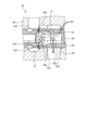
- FIG. 4 is a sectional view showing the structure of a hydraulic valve applied to the circuit diagram shown in FIG.
- FIG. 5 is an enlarged sectional view of a main part of the hydraulic valve shown in FIG. 4.
- the hydraulic circuit illustrated here is for operating the hydraulic cylinder 1 with oil supplied from a hydraulic pump.
- the hydraulic cylinder 1 is a single-rod double-acting type equipped with a single piston 2.
- a hydraulic cylinder 1 for operating a boom 3 in a working machine is illustrated.
- the working machine has an upper revolving body 5 disposed above a lower traveling body 4 so as to be rotatable around a vertical pivot axis, and the upper revolving body 5 is equipped with a boom 3.
- the boom 3 is rotatably supported by the upper revolving body 5 via its base end by a boom support shaft extending in the horizontal direction.
- Reference numeral 6 in the figure is an arm provided at the tip of the boom 3, and reference numeral 7 is a bucket provided at the tip of the arm.
- the hydraulic cylinder 1 is connected to the upper revolving body 5 via a cylinder body 8 and to the boom 3 via a rod 9.
- a bottom oil passage 11 is connected to a bottom chamber 1a
- a rod oil passage 12 is connected to a rod chamber 1b.
- the bottom oil passage 11 branches into a first bottom oil passage 11A and a second bottom oil passage (meter-out oil passage) 11B in the middle.
- the rod oil passage 12 is bifurcated into a first rod oil passage 12A and a second rod oil passage 12B.
- the hydraulic circuit includes a hydraulic pump 20, a direction switching valve 30 for operating the hydraulic cylinder 1, and a flow rate control valve (hydraulic valve) 40.
- the hydraulic pump 20 is of a variable displacement type driven by an engine (not shown).
- a pump oil passage 22 having a check valve 21 is connected to a discharge port of the hydraulic pump 20.
- the directional switching valve 30 is operated by pilot pressure from an operation valve (not shown), and is configured to switch the connection state of the pump port 33 and the tank port 34 with respect to the first input/output port 31 and the second input/output port 32. It has been done. To explain in more detail, when the directional switching valve 30 is placed in the neutral position shown in FIG. 1, the two input/output ports 31 and 32, the pump port 33, and the tank port 34 are respectively blocked. When moved from this state to the left and placed in the extended position as shown in FIG. It is now connected to the tank port 34. On the other hand, when the neutral position is moved to the right and placed in the retracted position as shown in FIG. It will be connected.
- a first bottom oil passage 11A is connected to a first input/output port 31, and a first rod oil passage 12A is connected to a second input/output port 32.
- a pump oil passage 22 is connected to the pump port 33, and a tank oil passage 51 leading to an oil tank 50 is connected to the tank port 34.
- the flow rate control valve 40 is operated by pilot pressure from an operation valve (not shown), and switches the connection state of the drain port (second port) 42 and regeneration port 43 to the meter out port (first port) 41. It is structured as follows. More specifically, when the flow control valve 40 is placed in the closed position shown in the figure, the meter out port 41, the drain port 42, and the regeneration port 43 are each cut off. When moved from this state to the left and placed at the control position as shown in the figure, the flow rate control valve 40 will be in a state where the meter out port 41 is connected to the drain port 42 and the regeneration port 43.
- a meter-out throttle 44 is provided between the meter-out port 41, the drain port 42, and the regeneration port 43 so that the opening area increases as the pilot pressure applied from the operating valve (not shown) increases.
- a drain-side fixed throttle 45 is provided between the meter-out port 41 and the drain port 42 downstream of the meter-out throttle 44.
- a check valve 46 and a regeneration-side fixed throttle 47 are provided downstream of the meter-out throttle 44 between the meter-out port 41 and the regeneration port 43 .
- a second bottom oil passage 11B is connected to a meter out port 41, and a tank oil passage 51 is connected to a drain port 42.
- the regeneration port 43 is connected to the second rod oil passage 12B.
- the flow control valve 40 includes a valve body 60 configured in a block shape.
- the valve body 60 is provided with a spool hole 61, and the above-mentioned meter out port 41, drain port 42, and regeneration port 43 are provided so as to communicate with the spool hole 61.
- the spool hole 61 is a through hole with a circular cross section and a straight axis, and includes a spool 62 therein.
- the spool 62 is a cylindrical member having an outer diameter that fits into the spool hole 61, and is disposed in the valve body 60 so as to be movable along the axis of the spool hole 61.
- a return spring between the end of the spool 62 and the valve body 60 that biases the spool 62 to the right side in FIG. 48 (see FIG. 1), and a pressure chamber 49 (see FIG. 1) to which pilot pressure is supplied from an operating valve (not shown).
- the pressure chamber 49 moves the spool 62 against the spring force of the return spring 48 when pilot pressure is supplied from an operation valve (not shown) to place the directional control valve 30 in the retracted position. It functions to move it to the left.
- the meter out port 41, the drain port 42, and the regeneration port 43 are configured to have a portion surrounding the spool hole 61, and are provided at positions separated from each other in the axial direction of the spool 62.
- a drain port 42 and a regeneration port 43 are provided on both sides of the meter out port 41.
- the spool 62 is provided with a main passage portion 63.
- the main passage section 63 is a through hole formed in the axial center of the spool 62, and includes a reference area 63a, a meter-out area (first area) 63b, a tapered area (third area) 63c, and a drain area (second area). 63d and a valve region 63e.
- the reference region 63a is a hollow space with a circular cross section, and is configured to have a constant inner diameter.
- the meter-out area 63b is a hollow space with a circular cross section and a constant inner diameter, and is provided adjacent to the right side of the reference area 63a in FIG.
- the meter-out area 63b has an inner diameter larger than the reference area 63a.
- a meter-out passage portion (first passage portion) 63f for forming the meter-out throttle 44 described above is formed in the meter-out region 63b.
- the meter-out passage section 63f is a through hole with a circular cross section formed along the radial direction of the spool 62, and a plurality of through holes having different cross sectional areas are formed in parallel in the circumferential direction and the axial direction. There is.
- meter-out passage portions 63f are completely covered by the land portion 60a located between the meter-out port 41 and the drain port 42 in the valve body 60 when the spool 62 is placed in the normal position. Become. On the other hand, when the spool 62 moves to the left with respect to the valve body 60, the meter-out passage section 63f opens to the meter-out port 41, and the opening area between the main passage section 63 and the meter-out port 41 It functions to gradually increase the
- the tapered region 63c is a space provided adjacent to the right side of the meter-out region 63b, and is formed in a tapered shape whose inner diameter gradually decreases toward the right side.
- the inner diameter of the tapered region 63c decreases at a constant rate, and the inner circumferential surface extends linearly in a cross section including the axis.
- the tapered region 63c is formed such that the inclination angle ⁇ with respect to the meter-out region 63b is 21°.
- the inclination angle ⁇ of the tapered region 63c is preferably in the range of 15 to 30 degrees.
- the rate at which the inner diameter decreases toward the right side along the axial direction is in the range of tan 15° to tan 30°.
- the inner diameter of the rightmost portion of the tapered region 63c is set to be larger than the reference region 63a and smaller than the meter-out region 63b.
- the drain region 63d is a hollow space with a circular cross section and a constant inner diameter provided adjacent to the right side of the tapered region 63c.
- the inner diameter of the drain region 63d is the same as the narrowest diameter portion of the tapered region 63c.
- This drain region 63d is provided with a drain passage portion (second passage portion) 63g for forming the above-mentioned drain side fixed throttle 45.
- the drain passage portions 63g are through holes formed along the radial direction of the spool 62 and have a circular cross section, and are formed in plurality so as to be equally spaced from each other along the circumferential direction.
- drain passage portions 63g are always connected to the drain port 42 from the state in which the spool 62 is placed in the normal position to the state in which the spool 62 moves to the left and all meter-out passage portions 63f open to the meter-out port 41. It is set up so that it communicates with the.
- a plug 64 is attached to a portion of the main passage portion 63 on the right side of the drain region 63d.
- the valve region 63e is a hollow space with a circular cross section provided adjacent to the left side of the reference region 63a.
- This valve region 63e accommodates a valve body 65 and a return spring 66 for forming the above-mentioned check valve 46, and is also provided with a regeneration passage portion 63h for forming the above-mentioned regeneration-side fixed throttle 47. be.
- the valve body 65 blocks the flow of oil between the reference region 63a and the valve seat portion 63i when it comes into contact with the valve seat portion 63i provided between the reference region 63a and the valve region 63e. Allow oil to flow between them when separated.
- the return spring 66 is interposed between the valve body 65 and a plug 67 attached to the left side of the valve region 63e in the main passage section 63, and is attached so that the valve body 65 is always in contact with the valve seat section 63i. It is something that strengthens.
- the regeneration passage portion 63h is a through hole formed along the radial direction of the spool 62 and has a circular cross section, and a plurality of regeneration passage portions 63h are formed at equal intervals from each other along the circumferential direction.
- the flow rate of oil passing through the flow control valve 40 can be accurately and finely controlled, and the operability of the boom 3 in the working machine can be improved.
- the bubbles generated in the oil in the meter-out area 63b move to the taper area 63c and the drain area 63d, are discharged from the drain passage part 63g, and may remain in the meter-out area 63b and the meter-out passage part 63f. do not have. Thereby, it is possible to prevent erosion from occurring in the land portion 60a of the valve body 60, and there is no possibility that the sealing performance between the spool 62 and the valve body 60 will be impaired.
- a hydraulic cylinder for operating a boom of a working machine is exemplified, but the present invention is not limited thereto.
- the first port does not need to be a meter-out port
- the second port does not need to be a drain port.
- a tapered portion in which the inner diameter decreases at a constant rate is illustrated as the third region, the rate at which the inner diameter decreases from the first region to the second region changes and may be curved in a convex shape. It is also possible to configure the tapered portion to be curved concavely.
Abstract
In order to implement fine flow rate control while maintaining rigidity of a spool, the present invention provides a flow rate control valve 40 that performs control of the flow rate of oil reaching a drain port 42 via a main passage 63 from a meter-out port 41 by changing the surface area of an opening in a meter-out passage 63f relative to the meter-out port 41 in conjunction with the movement of a spool 62. The main passage 63 of the spool 62 includes: a meter-out region 63b where the meter-out passage 63f is provided; a drain region 63d where a drain passage 63g is provided; and a tapered region 63c that is continuous between the meter-out region 63b and the drain region 63d. The inner diameter of the meter-out region 63b is formed larger than the drain region 63d. The tapered region 63c is constituted in a tapered shape the inner diameter of which gradually decreases toward the drain region 63d.
Description
本発明は、バルブ本体の内部にスプールを備えた油圧バルブ及び油圧回路に関するものである。
The present invention relates to a hydraulic valve and a hydraulic circuit that include a spool inside the valve body.
この種の油圧バルブとしては、スプールの外周に溝部を設けたものが多く提供されている(例えば、特許文献1参照)。この油圧バルブでは、バルブ本体に対してスプールが軸方向に移動するものであるため、フローフォースの影響を受け易いという一面がある。すなわち、スプールの移動によってバルブ本体のポートが開き始めた場合、油が斜め方向に通過する。このため、スプールがポートを閉じる方向にフローフォースが発生し、微細な流量制御が困難になる等の問題を招来するおそれがある。
Many hydraulic valves of this type have a groove provided on the outer periphery of the spool (for example, see Patent Document 1). In this hydraulic valve, since the spool moves in the axial direction with respect to the valve body, it is easily affected by flow force. That is, when a port in the valve body begins to open due to movement of the spool, oil passes diagonally. Therefore, a flow force is generated in the direction in which the spool closes the port, which may cause problems such as making fine flow control difficult.
こうしたフローフォースの影響を小さくするため、スプールの内部に油通路を設けるようにしたものも提供されている。すなわち、この油圧バルブでは、スプールの内部に軸方向に沿った主通路を設けるとともに、主通路からスプールの外周面に開口するように径方向に沿って副通路を設けることにより、フローフォースを低減するようにしている(例えば、特許文献2参照)。
In order to reduce the influence of such flow force, there are also models in which an oil passage is provided inside the spool. In other words, this hydraulic valve reduces flow force by providing a main passage along the axial direction inside the spool and a sub passage along the radial direction opening from the main passage to the outer peripheral surface of the spool. (For example, see Patent Document 2).
ところで、流量制御を微細に行うには、スプールの外周面に多数の独立した副通路を開口させることが好ましい。スプールに多数の副通路を設けるには、加工上の問題から主通路の内径を増大させる必要がある。しかしながら、主通路の内径を増大させたスプールにあっては、十分な剛性を確保することが難しく、大きな油圧が作用した場合に撓む等の変形を来す懸念がある。
Incidentally, in order to finely control the flow rate, it is preferable to open a large number of independent sub passages on the outer peripheral surface of the spool. In order to provide a large number of sub passages in the spool, it is necessary to increase the inner diameter of the main passage due to processing problems. However, in a spool with an increased inner diameter of the main passage, it is difficult to ensure sufficient rigidity, and there is a concern that deformation such as bending may occur when a large hydraulic pressure is applied.
本発明は、上記実情に鑑みて、スプールの剛性を確保しつつ流量制御を微細に実施することのできる油圧バルブ及び油圧回路を提供することを目的とする。
In view of the above circumstances, it is an object of the present invention to provide a hydraulic valve and a hydraulic circuit that can finely control the flow rate while ensuring the rigidity of the spool.
上記目的を達成するため、本発明に係る油圧バルブは、互いに独立した第1ポート及び第2ポートを有するバルブ本体と、前記バルブ本体に対して軸心に沿って移動可能に配設されたスプールとを備え、前記スプールには、軸心部分に設けられた主通路部と、前記主通路部から外周面までの間に設けられ、前記第1ポートに連通可能となる第1通路部と、前記主通路部から外周面までの間に設けられ、前記第2ポートに連通可能となる第2通路部とが設けられ、前記スプールの移動に伴って前記第1ポートに対する前記第1通路部の開口面積を変化させることにより前記第1ポートから前記主通路部を経由して前記第2ポートに至る油の流量制御を行う油圧バルブであって、前記スプールの主通路部は、前記第1通路部が設けられる第1領域と、前記第2通路部が設けられる第2領域と、これら前記第1領域及び前記第2領域の間を連続させる第3領域とを有し、前記第1領域の内径が前記第2領域よりも大きく形成され、前記第3領域が前記第2領域に向けて内径が漸次減少するテーパ状に構成されていることを特徴とする。
In order to achieve the above object, a hydraulic valve according to the present invention includes a valve body having a first port and a second port independent of each other, and a spool disposed movably along an axis with respect to the valve body. The spool includes: a main passage section provided in the axial center portion; a first passage section provided between the main passage section and the outer circumferential surface and capable of communicating with the first port; A second passage is provided between the main passage and the outer circumferential surface and is capable of communicating with the second port, and as the spool moves, the first passage is connected to the first port. A hydraulic valve that controls the flow rate of oil from the first port to the second port via the main passage by changing an opening area, wherein the main passage of the spool is connected to the first passage. a first region in which the passage portion is provided, a second region in which the second passage portion is provided, and a third region that connects the first region and the second region; It is characterized in that the inner diameter is formed larger than the second region, and the third region has a tapered shape in which the inner diameter gradually decreases toward the second region.
本発明によれば、スプールにおいて第1通路部を形成する第1領域のみを太径に構成しているため、スプールに剛性上の問題を招来することなくフローフォースの影響を低減することができる。しかも、第1領域から第2領域に至る間に内径が漸次減少する第3領域が設けてあるため、第1ポートから主通路部に流入した油に気泡が生じたとしても第3領域をスムースに通過し、第1領域側に反転することなく第2領域に到達して第2ポートに排出されることになる。従って、第1領域に気泡が停滞したり、気泡が第1通路部を介してバルブ本体のランド部に到達するおそれがなく、バルブ本体のランド部にエロージョンが発生する懸念もない。これらの結果、スプールの位置を精度良く制御することができ、微細な流量制御が可能となる。
According to the present invention, since only the first region forming the first passage portion of the spool is configured to have a large diameter, the influence of flow force can be reduced without causing problems with the rigidity of the spool. . Moreover, since there is a third region where the inner diameter gradually decreases between the first region and the second region, even if air bubbles are generated in the oil flowing into the main passage from the first port, the third region can be smoothly moved. The liquid passes through the air, reaches the second area without being turned over to the first area, and is discharged to the second port. Therefore, there is no risk that air bubbles will stagnate in the first region or that air bubbles will reach the land portion of the valve body via the first passage portion, and there is no fear that erosion will occur in the land portion of the valve body. As a result, the position of the spool can be controlled with high precision, and fine flow control becomes possible.
以下、添付図面を参照しながら本発明に係る油圧バルブ及び油圧回路の好適な実施の形態について詳細に説明する。
Hereinafter, preferred embodiments of a hydraulic valve and a hydraulic circuit according to the present invention will be described in detail with reference to the accompanying drawings.
図1~図3は、本発明の実施の形態である油圧回路を示したものである。ここで例示する油圧回路は、油圧ポンプから供給された油によって油圧シリンダ1を動作させるためのものである。油圧シリンダ1は、単一のピストン2を備えた片ロッド複動型のものである。本実施の形態では、作業機械においてブーム3を動作させるための油圧シリンダ1を例示している。作業機械は、下部走行体4の上部に上部旋回体5が上下に沿った旋回軸回りに回転可能に配設されたもので、上部旋回体5にブーム3を備えている。ブーム3は、水平方向に沿ったブーム支持軸により、基端部を介して上部旋回体5に回転可能に支持させたものである。図中の符号6は、ブーム3の先端部に設けたアーム、符号7はアームの先端部に設けたバケットである。
1 to 3 show a hydraulic circuit according to an embodiment of the present invention. The hydraulic circuit illustrated here is for operating the hydraulic cylinder 1 with oil supplied from a hydraulic pump. The hydraulic cylinder 1 is a single-rod double-acting type equipped with a single piston 2. In this embodiment, a hydraulic cylinder 1 for operating a boom 3 in a working machine is illustrated. The working machine has an upper revolving body 5 disposed above a lower traveling body 4 so as to be rotatable around a vertical pivot axis, and the upper revolving body 5 is equipped with a boom 3. The boom 3 is rotatably supported by the upper revolving body 5 via its base end by a boom support shaft extending in the horizontal direction. Reference numeral 6 in the figure is an arm provided at the tip of the boom 3, and reference numeral 7 is a bucket provided at the tip of the arm.
油圧シリンダ1は、シリンダ本体8を介して上部旋回体5に連結してあり、かつロッド9を介してブーム3に連結してある。油圧シリンダ1が伸張動作した場合には、上部旋回体5に対してブーム3の先端部が上方に移動し、油圧シリンダ1が縮退動作した場合には、上部旋回体5に対してブーム3の先端部が下方に移動する。油圧シリンダ1には、ボトム室1aにボトム油路11が接続してあり、ロッド室1bにロッド油路12が接続してある。ボトム油路11は、途中で第1ボトム油路11A及び第2ボトム油路(メータアウト油路)11Bに2分岐している。同様に、ロッド油路12は、途中で第1ロッド油路12A及び第2ロッド油路12Bに2分岐している。
The hydraulic cylinder 1 is connected to the upper revolving body 5 via a cylinder body 8 and to the boom 3 via a rod 9. When the hydraulic cylinder 1 extends, the tip of the boom 3 moves upward relative to the upper rotating structure 5, and when the hydraulic cylinder 1 retracts, the tip of the boom 3 moves upward relative to the upper rotating structure 5. The tip moves downward. In the hydraulic cylinder 1, a bottom oil passage 11 is connected to a bottom chamber 1a, and a rod oil passage 12 is connected to a rod chamber 1b. The bottom oil passage 11 branches into a first bottom oil passage 11A and a second bottom oil passage (meter-out oil passage) 11B in the middle. Similarly, the rod oil passage 12 is bifurcated into a first rod oil passage 12A and a second rod oil passage 12B.
油圧回路は、油圧ポンプ20と、油圧シリンダ1を操作するための方向切換バルブ30と、流量制御バルブ(油圧バルブ)40とを有している。
The hydraulic circuit includes a hydraulic pump 20, a direction switching valve 30 for operating the hydraulic cylinder 1, and a flow rate control valve (hydraulic valve) 40.
油圧ポンプ20は、エンジン(図示せず)によって駆動される可変容量型のものである。油圧ポンプ20の吐出口には、チェックバルブ21を有したポンプ油路22が接続してある。
The hydraulic pump 20 is of a variable displacement type driven by an engine (not shown). A pump oil passage 22 having a check valve 21 is connected to a discharge port of the hydraulic pump 20.
方向切換バルブ30は、図示せぬ操作バルブからのパイロット圧によって動作し、第1入出力ポート31及び第2入出力ポート32に対してポンプポート33及びタンクポート34の接続状態を切り換えるように構成してある。より詳細に説明すると、方向切換バルブ30は、図1に示す中立位置に配置された場合、2つの入出力ポート31,32、ポンプポート33及びタンクポート34がそれぞれ遮断された状態となる。この状態から図2に示すように左に移動して伸長位置に配置されると、方向切換バルブ30は、第1入出力ポート31がポンプポート33に接続され、かつ第2入出力ポート32がタンクポート34に接続された状態となる。一方、中立位置から図3に示すように右に移動して縮退位置に配置されると、第1入出力ポート31がタンクポート34に接続され、かつ第2入出力ポート32がポンプポート33に接続された状態となる。この方向切換バルブ30には、第1入出力ポート31に第1ボトム油路11Aが接続してあり、第2入出力ポート32に第1ロッド油路12Aが接続してある。ポンプポート33には、ポンプ油路22が接続してあり、タンクポート34には油タンク50に至るタンク油路51が接続してある。
The directional switching valve 30 is operated by pilot pressure from an operation valve (not shown), and is configured to switch the connection state of the pump port 33 and the tank port 34 with respect to the first input/output port 31 and the second input/output port 32. It has been done. To explain in more detail, when the directional switching valve 30 is placed in the neutral position shown in FIG. 1, the two input/ output ports 31 and 32, the pump port 33, and the tank port 34 are respectively blocked. When moved from this state to the left and placed in the extended position as shown in FIG. It is now connected to the tank port 34. On the other hand, when the neutral position is moved to the right and placed in the retracted position as shown in FIG. It will be connected. In this directional switching valve 30, a first bottom oil passage 11A is connected to a first input/output port 31, and a first rod oil passage 12A is connected to a second input/output port 32. A pump oil passage 22 is connected to the pump port 33, and a tank oil passage 51 leading to an oil tank 50 is connected to the tank port 34.
流量制御バルブ40は、操作バルブ(図示せず)からのパイロット圧によって動作し、メータアウトポート(第1ポート)41に対してドレンポート(第2ポート)42及び再生ポート43の接続状態を切り替えるように構成してある。より具体的に説明すると、流量制御バルブ40は、図に示す閉止位置に配置された場合、メータアウトポート41、ドレンポート42及び再生ポート43がそれぞれ遮断された状態となる。この状態から図に示すように左に移動して制御位置に配置されると、流量制御バルブ40は、メータアウトポート41がドレンポート42及び再生ポート43に接続された状態となる。メータアウトポート41とドレンポート42及び再生ポート43との間には、操作バルブ(図示せず)から加えられるパイロット圧が増大するに従って開口面積が増大するようにメータアウト絞り44が設けてある。メータアウトポート41とドレンポート42との間には、メータアウト絞り44の下流にドレン側固定絞り45が設けてある。メータアウトポート41と再生ポート43との間には、メータアウト絞り44の下流にチェックバルブ46及び再生側固定絞り47が設けてある。この流量制御バルブ40には、メータアウトポート41に第2ボトム油路11Bが接続してあり、ドレンポート42にタンク油路51が接続してある。再生ポート43には、第2ロッド油路12Bが接続してある。
The flow rate control valve 40 is operated by pilot pressure from an operation valve (not shown), and switches the connection state of the drain port (second port) 42 and regeneration port 43 to the meter out port (first port) 41. It is structured as follows. More specifically, when the flow control valve 40 is placed in the closed position shown in the figure, the meter out port 41, the drain port 42, and the regeneration port 43 are each cut off. When moved from this state to the left and placed at the control position as shown in the figure, the flow rate control valve 40 will be in a state where the meter out port 41 is connected to the drain port 42 and the regeneration port 43. A meter-out throttle 44 is provided between the meter-out port 41, the drain port 42, and the regeneration port 43 so that the opening area increases as the pilot pressure applied from the operating valve (not shown) increases. A drain-side fixed throttle 45 is provided between the meter-out port 41 and the drain port 42 downstream of the meter-out throttle 44. A check valve 46 and a regeneration-side fixed throttle 47 are provided downstream of the meter-out throttle 44 between the meter-out port 41 and the regeneration port 43 . In this flow rate control valve 40, a second bottom oil passage 11B is connected to a meter out port 41, and a tank oil passage 51 is connected to a drain port 42. The regeneration port 43 is connected to the second rod oil passage 12B.
図4、図5は、流量制御バルブ40の具体的な構成を示したものである。以下、図4、図5を適宜参照しながら流量制御バルブ40の構成について詳述し、併せて本願発明の特徴部分について説明する。図からも明らかなように、この流量制御バルブ40は、ブロック状に構成したバルブ本体60を備えている。バルブ本体60には、スプール孔61が設けてあるとともに、スプール孔61に連通するように上述したメータアウトポート41、ドレンポート42、再生ポート43が設けてある。スプール孔61は、断面が円形で、軸心が直線に沿った貫通孔であり、内部にスプール62を備えている。スプール62は、スプール孔61に嵌合する外径を有した円柱状部材であり、スプール孔61の軸心に沿って移動可能となる状態でバルブ本体60に配設してある。図には明示していないが、スプール62の端部とバルブ本体60との間には、バルブ本体60に対してスプール62を図4中の右側に付勢して常態位置に維持するリターンバネ48(図1参照)が設けてあるとともに、操作バルブ(図示せず)からパイロット圧が供給される圧力室49(図1参照)が設けてある。圧力室49は、操作バルブ(図示せず)から方向切換バルブ30を縮退位置に配置するようにパイロット圧が供給された場合にリターンバネ48のバネ力に抗してスプール62を図4中の左側に移動させるように機能するものである。メータアウトポート41、ドレンポート42、再生ポート43は、スプール孔61の周囲を取り囲む部分を有するように構成したもので、スプール62の軸心方向において互いに離隔した位置に設けてある。図示の例では、メータアウトポート41を挟んで両側となる部分にドレンポート42及び再生ポート43が設けてある。
4 and 5 show the specific configuration of the flow rate control valve 40. Hereinafter, the configuration of the flow rate control valve 40 will be described in detail with reference to FIGS. 4 and 5 as appropriate, and the characteristic portions of the present invention will also be described. As is clear from the figure, the flow control valve 40 includes a valve body 60 configured in a block shape. The valve body 60 is provided with a spool hole 61, and the above-mentioned meter out port 41, drain port 42, and regeneration port 43 are provided so as to communicate with the spool hole 61. The spool hole 61 is a through hole with a circular cross section and a straight axis, and includes a spool 62 therein. The spool 62 is a cylindrical member having an outer diameter that fits into the spool hole 61, and is disposed in the valve body 60 so as to be movable along the axis of the spool hole 61. Although not clearly shown in the figure, there is a return spring between the end of the spool 62 and the valve body 60 that biases the spool 62 to the right side in FIG. 48 (see FIG. 1), and a pressure chamber 49 (see FIG. 1) to which pilot pressure is supplied from an operating valve (not shown). The pressure chamber 49 moves the spool 62 against the spring force of the return spring 48 when pilot pressure is supplied from an operation valve (not shown) to place the directional control valve 30 in the retracted position. It functions to move it to the left. The meter out port 41, the drain port 42, and the regeneration port 43 are configured to have a portion surrounding the spool hole 61, and are provided at positions separated from each other in the axial direction of the spool 62. In the illustrated example, a drain port 42 and a regeneration port 43 are provided on both sides of the meter out port 41.
スプール62には、主通路部63が設けてある。主通路部63は、スプール62の軸心部分に形成した貫通孔であり、基準領域63a、メータアウト領域(第1領域)63b、テーパ領域(第3領域)63c、ドレン領域(第2領域)63d、バルブ領域63eを有している。基準領域63aは、断面が円形の空所であり、一定の内径を有するように構成してある。
The spool 62 is provided with a main passage portion 63. The main passage section 63 is a through hole formed in the axial center of the spool 62, and includes a reference area 63a, a meter-out area (first area) 63b, a tapered area (third area) 63c, and a drain area (second area). 63d and a valve region 63e. The reference region 63a is a hollow space with a circular cross section, and is configured to have a constant inner diameter.
メータアウト領域63bは、一定の内径を有した断面が円形の空所であり、図4中において基準領域63aの右側に隣接して設けてある。メータアウト領域63bの内径は、基準領域63aよりも大きくなるように形成してある。このメータアウト領域63bには、上述したメータアウト絞り44を構成するためのメータアウト通路部(第1通路部)63fが形成してある。メータアウト通路部63fは、スプール62の径方向に沿って形成した断面が円形の貫通孔であり、互いに断面積が異なるものが周方向及び軸心方向に並設するように複数個ずつ形成してある。これらのメータアウト通路部63fは、スプール62が常態位置に配置された場合に、バルブ本体60においてメータアウトポート41とドレンポート42との間に位置するランド部60aによってすべてが覆われた状態となる。これに対してスプール62がバルブ本体60に対して左側に移動すると、メータアウト通路部63fは、メータアウトポート41に対して開口し、主通路部63とメータアウトポート41との間の開口面積を漸次増大するように機能する。
The meter-out area 63b is a hollow space with a circular cross section and a constant inner diameter, and is provided adjacent to the right side of the reference area 63a in FIG. The meter-out area 63b has an inner diameter larger than the reference area 63a. A meter-out passage portion (first passage portion) 63f for forming the meter-out throttle 44 described above is formed in the meter-out region 63b. The meter-out passage section 63f is a through hole with a circular cross section formed along the radial direction of the spool 62, and a plurality of through holes having different cross sectional areas are formed in parallel in the circumferential direction and the axial direction. There is. These meter-out passage portions 63f are completely covered by the land portion 60a located between the meter-out port 41 and the drain port 42 in the valve body 60 when the spool 62 is placed in the normal position. Become. On the other hand, when the spool 62 moves to the left with respect to the valve body 60, the meter-out passage section 63f opens to the meter-out port 41, and the opening area between the main passage section 63 and the meter-out port 41 It functions to gradually increase the
テーパ領域63cは、メータアウト領域63bの右側に隣接して設けた空所であり、右側に向けて内径が漸次減少するテーパ状に形成してある。このテーパ領域63cは、一定の割合で内径が減少しており、軸心を含む断面において内周面が直線状に延在している。図示の例では、メータアウト領域63bに対する傾斜角度θが21°となるようにテーパ領域63cが形成してある。テーパ領域63cの傾斜角度θは、15~30°の範囲であることが好ましい。換言すれば、軸心方向に沿って右側に行くに従って内径が減少する割合がtan15°~tan30°の範囲にあることが好ましい。テーパ領域63cのもっとも右側に位置する部分の内径は、基準領域63aよりも太径、かつメータアウト領域63bよりも細径となるように設定してある。
The tapered region 63c is a space provided adjacent to the right side of the meter-out region 63b, and is formed in a tapered shape whose inner diameter gradually decreases toward the right side. The inner diameter of the tapered region 63c decreases at a constant rate, and the inner circumferential surface extends linearly in a cross section including the axis. In the illustrated example, the tapered region 63c is formed such that the inclination angle θ with respect to the meter-out region 63b is 21°. The inclination angle θ of the tapered region 63c is preferably in the range of 15 to 30 degrees. In other words, it is preferable that the rate at which the inner diameter decreases toward the right side along the axial direction is in the range of tan 15° to tan 30°. The inner diameter of the rightmost portion of the tapered region 63c is set to be larger than the reference region 63a and smaller than the meter-out region 63b.
ドレン領域63dは、テーパ領域63cの右側に隣接して設けた一定の内径を有する断面が円形の空所である。ドレン領域63dの内径は、テーパ領域63cのもっとも細径となる部分と同一である。このドレン領域63dには、上述したドレン側固定絞り45を構成するためのドレン通路部(第2通路部)63gが設けてある。ドレン通路部63gは、スプール62の径方向に沿って形成した断面が円形の貫通孔であり、周方向に沿って互いに等間隔となるように複数形成してある。これらのドレン通路部63gは、スプール62が常態位置に配置された状態からスプール62が左側に移動してメータアウト通路部63fがすべてメータアウトポート41に開口した状態までの間、常時ドレンポート42に連通するように設けてある。主通路部63においてドレン領域63dよりも右側となる部分には、プラグ64が装着してある。
The drain region 63d is a hollow space with a circular cross section and a constant inner diameter provided adjacent to the right side of the tapered region 63c. The inner diameter of the drain region 63d is the same as the narrowest diameter portion of the tapered region 63c. This drain region 63d is provided with a drain passage portion (second passage portion) 63g for forming the above-mentioned drain side fixed throttle 45. The drain passage portions 63g are through holes formed along the radial direction of the spool 62 and have a circular cross section, and are formed in plurality so as to be equally spaced from each other along the circumferential direction. These drain passage portions 63g are always connected to the drain port 42 from the state in which the spool 62 is placed in the normal position to the state in which the spool 62 moves to the left and all meter-out passage portions 63f open to the meter-out port 41. It is set up so that it communicates with the. A plug 64 is attached to a portion of the main passage portion 63 on the right side of the drain region 63d.
バルブ領域63eは、基準領域63aの左側となる部分に隣接して設けた断面が円形の空所である。このバルブ領域63eには、上述したチェックバルブ46を構成するためのバルブボディ65及びリターンスプリング66が収容してあるとともに、上述した再生側固定絞り47を構成するための再生通路部63hが設けてある。バルブボディ65は、基準領域63aとバルブ領域63eとの間に設けたバルブシート部63iに当接した場合に互いの間の油の流通を阻止する一方、左側に移動してバルブシート部63iから離隔した場合に互いの間の油の流通を許容する。リターンスプリング66は、主通路部63においてバルブ領域63eよりも左側となる部分に装着したプラグ67とバルブボディ65との間に介在し、バルブボディ65を常時バルブシート部63iに当接するように付勢するものである。再生通路部63hは、スプール62の径方向に沿って形成した断面が円形の貫通孔であり、周方向に沿って互いに等間隔となるように複数形成してある。
The valve region 63e is a hollow space with a circular cross section provided adjacent to the left side of the reference region 63a. This valve region 63e accommodates a valve body 65 and a return spring 66 for forming the above-mentioned check valve 46, and is also provided with a regeneration passage portion 63h for forming the above-mentioned regeneration-side fixed throttle 47. be. The valve body 65 blocks the flow of oil between the reference region 63a and the valve seat portion 63i when it comes into contact with the valve seat portion 63i provided between the reference region 63a and the valve region 63e. Allow oil to flow between them when separated. The return spring 66 is interposed between the valve body 65 and a plug 67 attached to the left side of the valve region 63e in the main passage section 63, and is attached so that the valve body 65 is always in contact with the valve seat section 63i. It is something that strengthens. The regeneration passage portion 63h is a through hole formed along the radial direction of the spool 62 and has a circular cross section, and a plurality of regeneration passage portions 63h are formed at equal intervals from each other along the circumferential direction.
上記のように構成した油圧回路では、ブーム3の先端部を上昇させるように操作バルブ(図示せず)を動作させると、図2に示すように、流量制御バルブ40が常態位置に配置された状態で方向切換バルブ30が伸長位置に配置される。これにより、油圧ポンプ20から吐出された油がポンプ油路22及びボトム油路11を介して油圧シリンダ1のボトム室1aに供給される。これにより、油圧シリンダ1が伸長動作し、ブーム3の先端部が上方に移動することになる。
In the hydraulic circuit configured as described above, when the operating valve (not shown) is operated to raise the tip of the boom 3, the flow control valve 40 is placed in the normal position as shown in FIG. In this state, the directional control valve 30 is placed in the extended position. Thereby, oil discharged from the hydraulic pump 20 is supplied to the bottom chamber 1a of the hydraulic cylinder 1 via the pump oil passage 22 and the bottom oil passage 11. This causes the hydraulic cylinder 1 to extend and the tip of the boom 3 to move upward.
一方、ブーム3の先端部を下降させるように操作バルブ(図示せず)を動作させると、図3に示すように、方向切換バルブ30が縮退位置に配置されるとともに、流量制御バルブ40のスプール62がバルブ本体60に対して左側に移動し、操作バルブ(図示せず)から加えられるパイロット圧に応じてメータアウト通路部63f(メータアウト絞り44)の開口面積が変化する。これにより、ボトム油路11から排出される油の一部が第2ボトム油路11Bを介して流量制御バルブ40を経由し、メータアウト絞り44によって油タンク50に至る油の流量が制限されるとともに、流量制御バルブ40を経由した油の一部がチェックバルブ46、再生通路部63h(再生側固定絞り47)及び第2ロッド油路12Bを介して油圧シリンダ1のロッド室1bに再生されることになる。従って、流量制御バルブ40においてメータアウト通路部63fの開口面積を調整することにより、ブーム3やアーム6、バケット7の重量に抗して油圧シリンダ1が縮退する際の速度を制御することが可能となる。
On the other hand, when an operation valve (not shown) is operated to lower the tip of the boom 3, the directional control valve 30 is placed in the retracted position, and the spool of the flow control valve 40 is placed in the retracted position, as shown in FIG. 62 moves to the left with respect to the valve body 60, and the opening area of the meter-out passage portion 63f (meter-out throttle 44) changes depending on the pilot pressure applied from the operating valve (not shown). As a result, a part of the oil discharged from the bottom oil passage 11 passes through the second bottom oil passage 11B and the flow rate control valve 40, and the flow rate of the oil reaching the oil tank 50 is restricted by the meter-out throttle 44. At the same time, a part of the oil that has passed through the flow rate control valve 40 is recycled to the rod chamber 1b of the hydraulic cylinder 1 via the check valve 46, the regeneration passage section 63h (regeneration side fixed throttle 47), and the second rod oil passage 12B. It turns out. Therefore, by adjusting the opening area of the meter-out passage section 63f in the flow control valve 40, it is possible to control the speed at which the hydraulic cylinder 1 retracts against the weight of the boom 3, arm 6, and bucket 7. becomes.
この間、上述の流量制御バルブ40によれば、スプール62に設けた径方向のメータアウト通路部63fを通じて油が流通することになる。従って、第2ボトム油路11Bの油がスプール62の主通路部63に流入する際に生じるフローフォースの影響を低減することができ、メータアウト通路部63fの開口面積を正確に調整することが可能となる。しかも、メータアウト通路部63fを形成するためのメータアウト領域63bは、内径が大きく形成してあるため、多数のメータアウト通路部63fを相互に干渉することなく形成することが可能となる。加えて、スプール62においては、内径を大きく構成した部分がメータアウト領域63bのみであるため、大きな油圧が作用した場合にも撓む等の問題を招来するおそれがない。これらの結果、流量制御バルブ40を通過する油の流量を正確、かつ微細に制御することができ、作業機械におけるブーム3の操作性を向上させることが可能となる。
During this time, according to the above-described flow control valve 40, oil flows through the radial meter-out passage section 63f provided in the spool 62. Therefore, it is possible to reduce the influence of flow force that occurs when the oil in the second bottom oil passage 11B flows into the main passage part 63 of the spool 62, and it is possible to accurately adjust the opening area of the meter-out passage part 63f. It becomes possible. Furthermore, since the meter-out region 63b for forming the meter-out passage portion 63f is formed to have a large inner diameter, it is possible to form a large number of meter-out passage portions 63f without mutual interference. In addition, since the only part of the spool 62 that has a large inner diameter is the meter-out area 63b, there is no risk of problems such as bending even when a large hydraulic pressure is applied. As a result, the flow rate of oil passing through the flow control valve 40 can be accurately and finely controlled, and the operability of the boom 3 in the working machine can be improved.
ところで、第2ボトム油路11Bからスプール62の主通路部63に油が流入する際には圧力が低下するため、油に気泡が生じることになる。この気泡は、バルブ本体60のランド部60aによって閉塞されたメータアウト通路部63fにおいて崩壊すると、ランド部60aにエロージョンを招来する原因となり、スプール62とバルブ本体60との間のシール性に影響を及ぼす懸念がある。しかしながら、上述の流量制御バルブ40によれば、メータアウト領域63bとドレン領域63dとの間に内径が漸次減少するようにテーパ領域63cが設けてあるため、主通路部63においては油が反転することなくスムースに下流に流れることになる。従って、メータアウト領域63bにおいて油に生じた気泡は、テーパ領域63c及びドレン領域63dに移動してドレン通路部63gから外部に排出され、メータアウト領域63bやメータアウト通路部63fに滞留するおそれがない。これにより、バルブ本体60のランド部60aにエロージョンが生じる事態を防止することができ、スプール62とバルブ本体60との間のシール性が損なわれるおそれがなくなる。
By the way, when the oil flows into the main passage portion 63 of the spool 62 from the second bottom oil passage 11B, the pressure decreases, so air bubbles are generated in the oil. When these bubbles collapse in the meter-out passage section 63f that is blocked by the land section 60a of the valve body 60, they cause erosion in the land section 60a, which affects the sealing performance between the spool 62 and the valve body 60. There are concerns that However, according to the above-described flow control valve 40, since the tapered region 63c is provided between the meter-out region 63b and the drain region 63d so that the inner diameter gradually decreases, the oil is reversed in the main passage portion 63. It will flow smoothly downstream without any problems. Therefore, the bubbles generated in the oil in the meter-out area 63b move to the taper area 63c and the drain area 63d, are discharged from the drain passage part 63g, and may remain in the meter-out area 63b and the meter-out passage part 63f. do not have. Thereby, it is possible to prevent erosion from occurring in the land portion 60a of the valve body 60, and there is no possibility that the sealing performance between the spool 62 and the valve body 60 will be impaired.
なお、上述した実施の形態では、作業機械のブームを動作するための油圧シリンダを例示しているが、本発明はこれに限定されない。この場合、第1ポートがメータアウトポートである必要もなく、第2ポートがドレンポートである必要もない。また、第3領域として一定の割合で内径が減少するテーパ部を例示しているが、第1領域から第2領域に向けて内径が減少する割合が変化し、凸状に湾曲していても良いし、凹状に湾曲するようにテーパ部を構成することも可能である。
Note that in the embodiments described above, a hydraulic cylinder for operating a boom of a working machine is exemplified, but the present invention is not limited thereto. In this case, the first port does not need to be a meter-out port, and the second port does not need to be a drain port. In addition, although a tapered portion in which the inner diameter decreases at a constant rate is illustrated as the third region, the rate at which the inner diameter decreases from the first region to the second region changes and may be curved in a convex shape. It is also possible to configure the tapered portion to be curved concavely.
1 油圧シリンダ
1a ボトム室
11B 第2ボトム油路
40 流量制御バルブ
41 メータアウトポート
42 ドレンポート
50 油タンク
51 タンク油路
60 バルブ本体
62 スプール
63 主通路部
63b メータアウト領域
63c テーパ領域
63d ドレン領域
63f メータアウト通路部
63g ドレン通路部 1Hydraulic cylinder 1a Bottom chamber 11B 2nd bottom oil passage 40 Flow rate control valve 41 Meter out port 42 Drain port 50 Oil tank 51 Tank oil passage 60 Valve body 62 Spool 63 Main passage 63b Meter out area 63c Tapered area 63d Drain area 63f Meter out passage 63g Drain passage
1a ボトム室
11B 第2ボトム油路
40 流量制御バルブ
41 メータアウトポート
42 ドレンポート
50 油タンク
51 タンク油路
60 バルブ本体
62 スプール
63 主通路部
63b メータアウト領域
63c テーパ領域
63d ドレン領域
63f メータアウト通路部
63g ドレン通路部 1
Claims (4)
- 互いに独立した第1ポート及び第2ポートを有するバルブ本体と、
前記バルブ本体に対して軸心に沿って移動可能に配設されたスプールとを備え、
前記スプールには、軸心部分に設けられた主通路部と、前記主通路部から外周面までの間に設けられ、前記第1ポートに連通可能となる第1通路部と、前記主通路部から外周面までの間に設けられ、前記第2ポートに連通可能となる第2通路部とが設けられ、
前記スプールの移動に伴って前記第1ポートに対する前記第1通路部の開口面積を変化させることにより前記第1ポートから前記主通路部を経由して前記第2ポートに至る油の流量制御を行う油圧バルブであって、
前記スプールの主通路部は、前記第1通路部が設けられる第1領域と、前記第2通路部が設けられる第2領域と、これら前記第1領域及び前記第2領域の間を連続させる第3領域とを有し、前記第1領域の内径が前記第2領域よりも大きく形成され、前記第3領域が前記第2領域に向けて内径が漸次減少するテーパ状に構成されていることを特徴とする油圧バルブ。 a valve body having a first port and a second port independent of each other;
a spool disposed movably along the axis with respect to the valve body,
The spool includes a main passage section provided at the axial center portion, a first passage section provided between the main passage section and the outer peripheral surface and capable of communicating with the first port, and the main passage section. a second passage portion provided between the second port and the outer circumferential surface and capable of communicating with the second port;
The flow rate of oil from the first port to the second port via the main passage is controlled by changing the opening area of the first passage with respect to the first port as the spool moves. A hydraulic valve,
The main passage part of the spool includes a first area where the first passage part is provided, a second area where the second passage part is provided, and a second area that connects the first area and the second area. 3 regions, the first region has an inner diameter larger than the second region, and the third region has a tapered shape in which the inner diameter gradually decreases toward the second region. Features hydraulic valve. - 前記第3領域は、前記第1領域から前記第2領域に向けて一定の割合で内径が減少していることを特徴とする請求項1に記載の油圧バルブ。 The hydraulic valve according to claim 1, wherein the third region has an inner diameter decreasing at a constant rate from the first region to the second region.
- 前記第3領域は、前記主通路部の軸心方向の長さに対して内径が減少する割合がtan15°~tan30°の範囲にあることを特徴とする請求項2に記載の油圧バルブ。 The hydraulic valve according to claim 2, wherein the inner diameter of the third region decreases at a rate of tan 15° to tan 30° relative to the length of the main passage in the axial direction.
- 請求項1~請求項3のいずれか一つに記載した油圧バルブの前記第1ポートに油圧シリンダのボトム室との間を連通するメータアウト油路が接続され、前記第2ポートに油タンクとの間を連通するタンク油路が接続されていることを特徴とする油圧回路。 A meter-out oil passage communicating with a bottom chamber of a hydraulic cylinder is connected to the first port of the hydraulic valve according to any one of claims 1 to 3, and an oil tank and an oil tank are connected to the second port. A hydraulic circuit characterized in that a tank oil path communicating between the two is connected.
Applications Claiming Priority (2)
| Application Number | Priority Date | Filing Date | Title |
|---|---|---|---|
| JP2022079738A JP2023168090A (en) | 2022-05-13 | 2022-05-13 | Hydraulic valve and hydraulic circuit |
| JP2022-079738 | 2022-05-13 |
Publications (1)
| Publication Number | Publication Date |
|---|---|
| WO2023218802A1 true WO2023218802A1 (en) | 2023-11-16 |
Family
ID=88730016
Family Applications (1)
| Application Number | Title | Priority Date | Filing Date |
|---|---|---|---|
| PCT/JP2023/013977 WO2023218802A1 (en) | 2022-05-13 | 2023-04-04 | Hydraulic valve and hydraulic circuit |
Country Status (2)
| Country | Link |
|---|---|
| JP (1) | JP2023168090A (en) |
| WO (1) | WO2023218802A1 (en) |
Citations (2)
| Publication number | Priority date | Publication date | Assignee | Title |
|---|---|---|---|---|
| JPH09159036A (en) * | 1995-12-08 | 1997-06-17 | Hitachi Constr Mach Co Ltd | Directional control valve |
| JP2002181004A (en) * | 2000-12-11 | 2002-06-26 | Yanmar Diesel Engine Co Ltd | Selector valve for boom cylinder of excavating and turning work vehicle |
-
2022
- 2022-05-13 JP JP2022079738A patent/JP2023168090A/en active Pending
-
2023
- 2023-04-04 WO PCT/JP2023/013977 patent/WO2023218802A1/en unknown
Patent Citations (2)
| Publication number | Priority date | Publication date | Assignee | Title |
|---|---|---|---|---|
| JPH09159036A (en) * | 1995-12-08 | 1997-06-17 | Hitachi Constr Mach Co Ltd | Directional control valve |
| JP2002181004A (en) * | 2000-12-11 | 2002-06-26 | Yanmar Diesel Engine Co Ltd | Selector valve for boom cylinder of excavating and turning work vehicle |
Also Published As
| Publication number | Publication date |
|---|---|
| JP2023168090A (en) | 2023-11-24 |
Similar Documents
| Publication | Publication Date | Title |
|---|---|---|
| JP6600386B1 (en) | Valve device | |
| WO2021059614A1 (en) | Flow control valve | |
| US10107309B2 (en) | Load sensing valve device | |
| WO2023218802A1 (en) | Hydraulic valve and hydraulic circuit | |
| KR20180121958A (en) | Fluid pressure control device | |
| WO2023218803A1 (en) | Hydraulic valve and hydraulic circuit | |
| KR20170038160A (en) | Direction converter valve and hydraulic system | |
| JPH07103882B2 (en) | Hydraulic valve with pressure compensation | |
| JP7423189B2 (en) | Control valves and hydraulic systems for construction machinery | |
| JP2019056464A (en) | Flow control valve | |
| WO2023189986A1 (en) | Flow rate control valve | |
| WO2023105872A1 (en) | Valve device | |
| JP7316423B2 (en) | flow control valve | |
| JP7349974B2 (en) | Hydraulic control equipment and hydraulic equipment | |
| JP7397561B2 (en) | valve device | |
| WO2023189508A1 (en) | Directional control valve | |
| JP7290946B2 (en) | Flow control valve and working machine | |
| JP2019060373A (en) | Hydraulic motor control device | |
| JP6898834B2 (en) | Fluid pressure controller | |
| JPH109415A (en) | Control valve with flow control valve and control valve with pressure control valve | |
| WO2021172098A1 (en) | Fluid pressure drive unit | |
| JP6836487B2 (en) | Control valve | |
| JP2021110360A (en) | Hydraulic circuit, direction switch valve for hydraulic circuit, and construction machine | |
| JP5134925B2 (en) | Flow control valve, directional control valve unit and hydraulic circuit | |
| KR20200094091A (en) | Control valve and direction switching valve |
Legal Events
| Date | Code | Title | Description |
|---|---|---|---|
| 121 | Ep: the epo has been informed by wipo that ep was designated in this application |
Ref document number: 23803285 Country of ref document: EP Kind code of ref document: A1 |