WO2023218665A1 - セル装置に収容される端末の数の予測 - Google Patents
セル装置に収容される端末の数の予測 Download PDFInfo
- Publication number
- WO2023218665A1 WO2023218665A1 PCT/JP2022/020274 JP2022020274W WO2023218665A1 WO 2023218665 A1 WO2023218665 A1 WO 2023218665A1 JP 2022020274 W JP2022020274 W JP 2022020274W WO 2023218665 A1 WO2023218665 A1 WO 2023218665A1
- Authority
- WO
- WIPO (PCT)
- Prior art keywords
- prediction
- terminals
- cell
- learning
- accommodated
- Prior art date
- Legal status (The legal status is an assumption and is not a legal conclusion. Google has not performed a legal analysis and makes no representation as to the accuracy of the status listed.)
- Ceased
Links
Images









Classifications
-
- H—ELECTRICITY
- H04—ELECTRIC COMMUNICATION TECHNIQUE
- H04W—WIRELESS COMMUNICATION NETWORKS
- H04W24/00—Supervisory, monitoring or testing arrangements
- H04W24/02—Arrangements for optimising operational condition
-
- H—ELECTRICITY
- H04—ELECTRIC COMMUNICATION TECHNIQUE
- H04W—WIRELESS COMMUNICATION NETWORKS
- H04W4/00—Services specially adapted for wireless communication networks; Facilities therefor
- H04W4/02—Services making use of location information
- H04W4/029—Location-based management or tracking services
-
- H—ELECTRICITY
- H04—ELECTRIC COMMUNICATION TECHNIQUE
- H04W—WIRELESS COMMUNICATION NETWORKS
- H04W64/00—Locating users or terminals or network equipment for network management purposes, e.g. mobility management
Definitions
- the present invention relates to predicting the number of terminals accommodated in a cell device.
- Patent Document 1 describes calculating a predicted traffic value for a certain point in a network based on the traffic history at that point.
- the present invention has been made in view of the above circumstances, and one of its purposes is to improve the accuracy of predicting the number of terminals accommodated in a cell device.
- a prediction device includes a terminal number information acquisition means, a movement direction information acquisition means, and a prediction means.
- the terminal number information obtaining means obtains terminal number information indicating the number of terminals accommodated in each of a plurality of cell devices constituting the wireless communication system at a first time point.
- the movement direction information acquisition means acquires movement direction information indicating the movement direction of each terminal at the first time point.
- the prediction means predicts the number of terminals accommodated in each of the plurality of cell devices at a second time point that is a predetermined time after the first time point, based on the terminal number information and the moving direction information. do.
- a prediction method includes acquiring terminal number information indicating the number of terminals accommodated in each of a plurality of cell devices constituting a wireless communication system at a first point in time; acquiring moving direction information indicating the moving direction of the terminal; and based on the terminal number information and the moving direction information, each of the plurality of cell devices at a second time point that is a predetermined time after the first time point; and predicting the number of the terminals accommodated in the terminal.
- An information storage medium includes a procedure for acquiring terminal number information indicating the number of terminals accommodated in each of a plurality of cell devices constituting a wireless communication system at a first time point, A procedure for acquiring moving direction information indicating the moving direction of a terminal, based on the terminal number information and the moving direction information, to each of the plurality of cell devices at a second point in time that is a predetermined time after the first point in time.
- the information storage medium stores a program that causes a computer to execute a procedure for predicting the number of terminals to be accommodated.
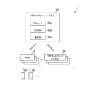
- FIG. 1 is a diagram showing an example of a communication system according to an embodiment of the present invention.
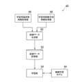
- FIG. 2 is a functional block diagram showing an example of functions implemented in a learning device according to an embodiment of the present invention.
- FIG. 2 is a functional block diagram showing an example of functions implemented in a prediction device according to an embodiment of the present invention. It is a figure showing an example of training data.
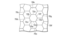
- FIG. 3 is a diagram schematically showing an example of a cell.
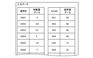
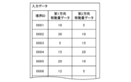
- FIG. 2 is a diagram schematically showing an example of learning of a machine learning model. It is a figure showing an example of input data.
- FIG. 3 is a diagram schematically showing an example of prediction using a trained machine learning model.
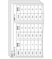
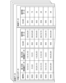
- FIG. 3 is a diagram showing an example of estimated output data. It is a figure showing an example of training data. It is a figure showing an example of input data. It is a figure showing an example of training data. It is a figure showing an example of input data. It is a figure showing an example of training data. It is a figure showing an example of input data. It is a figure showing an example of input data. It is a figure showing an example of input data. It is a figure showing an example of input data.
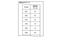
- FIG. 3 is a diagram showing an example of estimated output data.
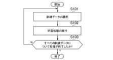
- FIG. 2 is a flow diagram showing an example of the flow of processing performed by the learning device according to an embodiment of the present invention. It is a flow diagram showing an example of the flow of processing performed by the prediction device concerning one embodiment of the present invention.
- FIG. 1 and 2 are diagrams showing an example of a communication system 1 according to an embodiment of the present invention.
- the communication system 1 according to this embodiment includes a wireless communication system.
- FIG. 1 is a diagram focusing on the locations of a data center group included in a communication system 1.
- FIG. 2 is a diagram focusing on various computer systems implemented in a data center group included in the communication system 1.
- the data center group included in the communication system 1 is classified into a central data center 10, a regional data center 12, and an edge data center 14.
- central data centers 10 are distributed within the area covered by the communication system 1 (for example, within Japan).
- regional data centers 12 are distributed within the area covered by the communication system 1. For example, if the area covered by the communication system 1 is the entire country of Japan, one to two regional data centers 12 may be placed in each prefecture.
- each of the edge data centers 14 is capable of communicating with a communication facility 18 equipped with an antenna 16.
- Communication equipment 18 may include a computer such as a server computer.
- the communication equipment 18 according to the present embodiment performs wireless communication with a UE (User Equipment) 20 via the antenna 16.
- the communication equipment 18 equipped with the antenna 16 corresponds to an example of a cell device according to the present embodiment, and the communication equipment 18 is provided with, for example, an RU (Radio Unit).
- a plurality of servers are arranged in each of the central data center 10, regional data center 12, and edge data center 14 according to this embodiment.
- the central data center 10, the regional data center 12, and the edge data center 14 can communicate with each other.
- the central data centers 10, the regional data centers 12, and the edge data centers 14 can also communicate with each other.
- the communication system 1 includes a platform system 30, multiple radio access networks (RAN) 32, multiple core network systems 34, and multiple terminals (UE 20). .
- the core network system 34, RAN 32, and UE 20 cooperate with each other to realize a mobile communication network.
- the RAN 32 is an antenna that corresponds to an eNB (eNodeB) in a fourth generation mobile communication system (hereinafter referred to as 4G) or a gNB (NR base station) in a fifth generation mobile communication system (hereinafter referred to as 5G). It is a computer system equipped with 16.
- the RAN 32 according to this embodiment is mainly implemented by a server group and communication equipment 18 located in the edge data center 14. Note that a part of the RAN 32 (for example, DU (Distributed Unit), CU (Central Unit), vDU (virtual Distributed Unit), vCU (virtual Central Unit)) is located not in the edge data center 14 but in the central data center 10 or regional It may also be implemented at data center 12.
- DU Distributed Unit
- CU Central Unit
- vDU virtual Distributed Unit
- vCU virtual Central Unit
- the core network system 34 is a system equivalent to EPC (Evolved Packet Core) in 4G and 5G core (5GC) in 5G.
- the core network system 34 according to this embodiment is mainly implemented by a group of servers located in the central data center 10 and the regional data center 12.
- the platform system 30 is configured on a cloud infrastructure, for example, and includes a processor 30a, a storage section 30b, and a communication section 30c, as shown in FIG.
- the processor 30a is a program-controlled device such as a microprocessor that operates according to a program installed in the platform system 30.
- the storage unit 30b is, for example, a storage element such as ROM or RAM, a solid state drive (SSD), a hard disk drive (HDD), or the like.
- the storage unit 30b stores programs and the like executed by the processor 30a.
- the communication unit 30c is, for example, a communication interface such as a NIC (Network Interface Controller) or a wireless LAN (Local Area Network) module. Note that SDN (Software-Defined Networking) may be implemented in the communication unit 30c.
- the communication unit 30c exchanges data with the RAN 32 and the core network system 34.
- the platform system 30 is implemented by a group of servers located in the central data center 10 or the regional data center 12.
- the requested network service is constructed in the RAN 32 or the core network system 34.
- the constructed network service is then provided to the purchaser.
- network services such as voice communication services and data communication services are provided to purchasers who are MVNOs (Mobile Virtual Network Operators).
- the voice communication service and data communication service provided by this embodiment are ultimately provided to the customer (end user) of the purchaser (MVNO in the above example) using the UE20 shown in FIGS. 1 and 2.
- the end user can perform voice communication and data communication with other users via the RAN 32 and the core network system 34. Further, the end user's UE 20 can access a data network such as the Internet via the RAN 32 and the core network system 34.
- IoT Internet of Things
- end users who use robot arms, connected cars, and the like.
- an end user who uses a robot arm, a connected car, etc. may become a purchaser of the network service according to this embodiment.
- a container-type virtualization application execution environment such as Docker (registered trademark) is installed on the servers located in the central data center 10, regional data center 12, and edge data center 14. It is now possible to deploy and run containers on these servers.
- a cluster composed of one or more containers generated by such virtualization technology may be constructed.
- a Kubernetes cluster managed by a container management tool such as Kubernetes (registered trademark) may be constructed.
- processors on the constructed cluster may execute container-type applications.
- the network service provided to the purchaser is composed of one or more functional units (for example, a network function (NF)).
- the functional unit is implemented as an NF realized by virtualization technology.
- NF realized by virtualization technology is called VNF (Virtualized Network Function).
- VNF Virtualized Network Function
- CNF Containerized Network Function
- container-type virtualization technology is also included in the VNF in this description.
- the network service is implemented by one or more CNFs.
- the functional unit according to this embodiment may correspond to a network node.
- the platform system 30 predicts, for example, the number of UEs 20 accommodated in each of a plurality of cell devices that constitute a wireless communication system.
- the elements included in the communication system 1 are controlled. For example, based on the prediction result for a certain cell device, scale-out or scale-in of the functional unit associated with the cell device is executed. For example, when the predicted number of UEs 20 for a certain cell device satisfies a predetermined scale-out condition, the DUs and CUs that process communication by the UEs 20 accommodated in the cell device are scaled out. Further, when the predicted number of UEs 20 for a certain cell device satisfies a predetermined scale-in condition, DUs and CUs that process communication by the UEs 20 accommodated in the cell device are scaled in.
- the functions of the platform system 30 according to the present embodiment and the platform system 30 according to the present embodiment will be described, focusing on prediction of the number of UEs 20 accommodated in a cell device and control of elements included in the communication system 1. The processing executed in will be further explained.
- the platform system 30 includes, for example, a learning device 40 shown in FIG. 3 and a prediction device 42 shown in FIG. 4.
- the prediction device 42 uses the machine learning model 44 (learned model) that has been trained by the learning device 40 to predict the cell of each of the plurality of cell devices included in the communication system 1. Predict the number of UEs 20 accommodated in the device.
- FIG. 3 is a functional block diagram showing an example of functions implemented in the learning device 40 included in the platform system 30 according to the present embodiment. Note that the platform system 30 according to this embodiment does not need to implement all of the functions shown in FIG. 3, and functions other than those shown in FIG. 3 may be implemented.
- the learning device 40 functionally includes, for example, a machine learning model 44, a learning terminal number information acquisition unit 46, a learning movement direction information acquisition unit 48, and a training data generation unit.
- a training data storage section 52, a learning section 54 are included.
- the machine learning model 44 is mainly implemented using the processor 30a and the storage unit 30b.
- the learning terminal number information acquisition section 46 and the learning movement direction information acquisition section 48 are mainly implemented using the storage section 30b and the communication section 30c.
- the training data generation section 50 and the learning section 54 are mainly implemented in the processor 30a.
- the training data storage section 52 is mainly implemented using the storage section 30b.
- the functions shown in FIG. 3 may be installed in the learning device 40, which is one or more computers, and implemented by the processor 30a executing a program containing instructions corresponding to the functions.
- This program may be supplied to the learning device 40 via a computer-readable information storage medium such as an optical disk, a magnetic disk, a magnetic tape, a magneto-optical disk, or a flash memory, or via the Internet.
- the functions shown in FIG. 3 may be implemented using circuit blocks, memories, or other LSIs. Further, those skilled in the art will understand that the functionality shown in FIG. 3 can be implemented in various forms, such as only hardware, only software, or a combination thereof.
- FIG. 4 is a functional block diagram showing an example of functions implemented in the prediction device 42 included in the platform system 30 according to the present embodiment. Note that the prediction device 42 according to this embodiment does not need to implement all of the functions shown in FIG. 4, and functions other than those shown in FIG. 4 may be implemented.
- the prediction device 42 functionally includes, for example, a machine learning model 44, a prediction terminal number information acquisition unit 56, a prediction movement direction information acquisition unit 58, an input data generation A prediction unit 60, a prediction unit 62, a determination unit 64, and a control unit 66 are included.
- the machine learning model 44 is mainly implemented using the processor 30a and the storage unit 30b.
- the prediction terminal number information acquisition section 56 and the prediction movement direction information acquisition section 58 are mainly implemented in the communication section 30c.
- the input data generation section 60, the prediction section 62, and the determination section 64 are mainly implemented in the processor 30a.
- the control unit 66 is mainly implemented with a processor 30a and a communication unit 30c.
- the functions shown in FIG. 4 may be installed in the prediction device 42, which is one or more computers, and implemented by the processor 30a executing a program containing instructions corresponding to the functions.
- This program may be supplied to the prediction device 42 via a computer-readable information storage medium such as an optical disk, a magnetic disk, a magnetic tape, a magneto-optical disk, or a flash memory, or via the Internet.
- the functions shown in FIG. 4 may be implemented using circuit blocks, memories, or other LSIs. Further, those skilled in the art will understand that the functionality shown in FIG. 4 can be implemented in various forms, such as only hardware, only software, or a combination thereof.
- the learning device 40 is located in the central data center 10. Further, it is assumed that the prediction device 42 is placed in each of the plurality of regional data centers 12, for example.
- the learning device 40 may be placed in the regional data center 12 or the edge data center 14, and the prediction device 42 may be placed in the central data center 10 or the edge data center 14.
- the machine learning model 44 is, for example, a machine learning model such as a neural network or a decision tree. Note that the machine learning model 44 according to this embodiment does not need to be a neural network or a decision tree.
- the learning terminal number information acquisition unit 46 acquires, for example, learning terminal number information indicating the number of UEs 20 accommodated in each of a plurality of cell devices configuring a wireless communication system.
- an element such as an RU, DU, or CU may monitor the number of UEs 20 accommodated in the cell device within the coverage area of the element. Then, learning terminal number information indicating the number of UEs 20 in which the element is accommodated in the cell device may be transmitted to the learning device 40. Then, the learning terminal number information acquisition unit 46 may receive the learning terminal number information transmitted in this manner. Note that the learning terminal number information may be transmitted and received repeatedly. Further, the information on the number of learning terminals may be transmitted and received at predetermined time intervals.
- the learning movement direction information acquisition unit 48 acquires learning movement direction information indicating the movement direction of each UE 20, for example.
- the learning movement direction information is information indicating the cell device in which the UE 20 was accommodated before the movement and the cell device in which the UE 20 was accommodated after the movement, when the UE 20 moves across the cell boundary. Good too.
- an element of the RAN 32 such as an RU, DU, or CU may transmit a copy of signaling information for handover between cells included in the coverage area of the element to the learning device 40 as learning movement direction information. good. Then, the learning moving direction information acquisition unit 48 may receive the learning moving direction information transmitted in this manner.
- elements of the core network system 34 such as MME (Mobility Management Entity), AMF (Access and Mobility Management Function), and SMF (Session Management Function), provide handover signaling information between cells included in the coverage area of the element.
- MME Mobility Management Entity
- AMF Access and Mobility Management Function
- SMF Session Management Function
- Inter-cell handover signaling information is used for learning when the UE 20 moves across cell boundaries, indicating the cell device in which the UE 20 was accommodated before the movement and the cell device in which the UE 20 was accommodated after the movement. This corresponds to an example of movement direction information.
- the learning terminal number information and the learning moving direction information are acquired over a certain length of time (for example, one week, one month, one year, etc.). Then, the learning terminal number information acquisition unit 46 holds the acquired learning terminal number information. Further, the learning moving direction information acquisition unit 48 holds the acquired learning moving direction information.
- the training data generation unit 50 generates, for example, the learning terminal number information acquired by the learning terminal number information acquisition unit 46 and the learning movement direction information acquired by the learning movement direction information acquisition unit 48. Based on this, training data illustrated in FIG. 5 is generated.
- the training data according to this embodiment includes learning input data and teacher data.
- the learning input data includes terminal number data associated with the cell ID and movement amount data associated with the boundary ID.
- the movement amount data includes first direction movement amount data and second direction movement amount data.
- the teacher data includes terminal number data associated with the cell ID.
- the cell ID is cell identification information (which can also be said to be cell device identification information).
- the boundary ID is identification information of the boundary between cells.
- FIG. 6 is a diagram schematically showing an example of the cell 70 according to the present embodiment.
- One cell 70 shown in FIG. 6 corresponds to the coverage area of one cell device associated with the cell 70, for example.
- cell 70a is adjacent to cell 70b via boundary 72a. Furthermore, the cell 70a is adjacent to the cell 70c via a boundary 72b. Furthermore, the cell 70a is adjacent to the cell 70d via a boundary 72c. Furthermore, the cell 70a is adjacent to the cell 70e via a boundary 72d. Furthermore, the cell 70a is adjacent to the cell 70f via a boundary 72e. Furthermore, the cell 70a is adjacent to the cell 70g via a boundary 72f.
- the cell ID is the identification information of the cell 70 shown in FIG. 6, that is, the identification information of the cell device whose coverage area is the cell 70.
- the boundary ID is identification information of the boundary 72 shown in FIG. 6.
- cell IDs of cell 70a, cell 70b, cell 70c, cell 70d, cell 70e, cell 70f, and cell 70g are 001, 002, 003, 004, 005, 006, and 007, respectively.
- boundary IDs of the boundary 72a, boundary 72b, boundary 72c, boundary 72d, boundary 72e, and boundary 72f are 0001, 0002, 0003, 0004, 0005, and 0006, respectively.
- Each of the plurality of training data according to the present embodiment is associated with a different point in time, for example.
- the time point associated with the training data will be referred to as a learning reference time point.
- a time point after a predetermined time for example, 30 minutes, 1 hour, etc.
- a learning comparison time point for example, 30 minutes, 1 hour, etc.
- the training data generation unit 50 selects information on the number of learning terminals held by the learning terminal number information acquisition unit 46 that is accommodated in each of a plurality of cell devices constituting the wireless communication system at the learning reference time. Terminal number information indicating the number of UEs 20 that are present is extracted.
- the training data generation unit 50 identifies the number of UEs 20 accommodated in each of the plurality of cell devices at the learning reference time based on the extracted terminal number information.
- the number of UEs 20 identified at the learning reference time in this way will be referred to as the number of terminals at the learning reference time.
- the training data generation unit 50 generates data for a predetermined period (for example, 30 minutes, 1 hour, etc.) up to the learning reference time from the learning terminal number information held by the learning terminal number information acquisition unit 46.
- the number of terminals information indicating the number of UEs 20 accommodated in each of the plurality of cell devices constituting the wireless communication system may be extracted.
- the training data generation unit 50 Based on the extracted terminal number information, the training data generation unit 50 generates a representative value of the number of UEs 20 accommodated in each of the plurality of cell devices (for example, , average value, maximum value, minimum value, etc.) may be calculated.
- the training data generation unit 50 may treat the representative value calculated in this manner as the value of the number of terminals at the learning reference point.
- the training data generation unit 50 extracts learning movement direction information indicating the movement direction of each UE 20 at the learning reference time from among the learning movement direction information held by the learning movement direction information acquisition unit 48.
- learning movement direction information indicating the movement direction of each UE 20 during a predetermined period up to the learning reference time is extracted as learning movement direction information indicating the movement direction of each UE 20 at the learning reference time. Good too.
- the training data generation unit 50 identifies the number of UEs 20 that have moved between cells at the learning reference time point based on the extracted learning movement direction information.
- the number of UEs 20 that moved between cells during a predetermined period of time (for example, 30 minutes, 1 hour, etc.) up to the relevant learning reference time is specified as the number of UEs 20 that moved between cells at the relevant learning reference time. It's okay.
- the number of UEs 20 that have moved across the boundary 72 is specified for each boundary 72.
- the number of UEs that have moved from a cell with a large cell ID value to a cell with a small cell ID value is specified as the number of learning reference first direction movements associated with the boundary 72.
- the number of UEs that have moved from a cell with a small cell ID value to a cell with a large cell ID value is specified as the learning reference second direction movement number associated with the boundary 72.
- the training data generation unit 50 selects, for example, each of the plurality of cell devices constituting the wireless communication system at the time of the learning comparison from among the learning terminal number information held by the learning terminal number information acquisition unit 46. Extract terminal number information indicating the number of accommodated terminals.
- the training data generation unit 50 identifies the number of UEs 20 accommodated in each of the plurality of cell devices at the time of the learning comparison based on the extracted terminal number information.
- the number of UEs 20 identified at the learning comparison time point in this way will be referred to as the number of terminals at the learning comparison time point.
- the training data generation unit 50 generates data for a predetermined period (for example, 30 minutes, 1 hour, etc.) up to the learning comparison time from the learning terminal number information held by the learning terminal number information acquisition unit 46.
- the number of terminals information indicating the number of UEs 20 accommodated in each of the plurality of cell devices constituting the wireless communication system may be extracted.
- the training data generation unit 50 Based on the extracted terminal number information, the training data generation unit 50 generates a representative value of the number of UEs 20 accommodated in each of the plurality of cell devices (for example, , average value, maximum value, minimum value, etc.) may be calculated.
- the training data generation unit 50 may treat the representative value calculated in this manner as the value of the number of terminals at the time of learning comparison.
- the training data generation unit 50 then associates the terminals with the learning reference time based on the number of terminals at the learning reference time, the number of learning reference movements in the first direction, the number of learning reference movements in the second direction, and the number of terminals at the learning comparison time. Generate training data to be used.
- the value of the number of terminals associated with a certain cell ID in the learning input data included in the training data associated with a certain learning reference time may include the learning information specified or calculated for the cell 70 corresponding to the cell ID.
- the value of the number of terminals at the reference time is set.
- the learning input data in FIG. 5 shows terminal number data in which the values of the number of terminals at the learning reference time point are set for cells 70a, 70b, 70c, 70d, 70e, and 70f. Note that in the learning input data shown in FIG. 5, the number of terminals data in which the value of the number of terminals at the learning reference point in time for the cell 70g is set is omitted.
- the value of the learning reference first direction movement amount calculated for the boundary 72 corresponding to the boundary ID is set to the value of the first direction movement amount data associated with a certain boundary ID of the learning input data. Ru.
- the value of the learning reference second direction movement amount calculated for the boundary 72 corresponding to the boundary ID is set to the value of the second direction movement amount data associated with a certain boundary ID of the learning input data. Ru.
- the learning input data in FIG. 5 includes first direction movement amount data in which learning reference first direction movement numbers are set for the boundaries 72a, 72b, 72c, 72d, 72e, and 72f. It is shown. Further, in the learning input data of FIG. 5, the second direction movement amount in which the value of the learning reference second direction movement number for the boundary 72a, boundary 72b, boundary 72c, boundary 72d, boundary 72e, and boundary 72f is set. Data are shown.
- the value of the number of terminals associated with a certain cell ID in the teacher data included in the training data is set to the value of the number of terminals at the time of learning comparison, which is specified or calculated for the cell 70 corresponding to the cell ID. be done.
- the teacher data shown in FIG. 5 includes terminal number data in which values of the number of terminals at the time of learning comparison are set for cells 70a, 70b, 70c, 70d, 70e, and 70f. ing.
- the number of terminals data in which the value of the number of terminals at the time of learning comparison for the cell 70g is set is omitted.
- the training data generation unit 50 causes the training data storage unit 52 to store the training data generated as described above.
- the training data storage unit 52 stores, for example, a plurality of pieces of training data generated by the training data generation unit 50.
- the learning unit 54 executes learning of the machine learning model 44 using, for example, training data stored in the training data storage unit 52.
- the learning unit 54 inputs learning input data included in the training data to the machine learning model 44. Then, the learning unit 54 acquires learning output data indicating the output from the machine learning model 44 according to the input. The learning unit 54 then identifies the difference between the value of the learning output data and the value of the teacher data included in the training data. The learning unit 54 then performs supervised learning to update the parameter values of the machine learning model 44 using the error backpropagation method so that the value of the loss function associated with the identified difference is minimized.
- the learning unit 54 may perform learning of the machine learning model 44 using a learning method other than the learning method described above.
- a copy of the machine learning model 44 (trained model) that has been trained by the learning unit 54 as described above is stored in the prediction device 42.
- a part of the copy of the machine learning model 44 may be stored in the prediction device 42.
- a portion of the learned model related to the cells 70 and boundaries 72 included in the coverage area of the regional data center 12 where the prediction device 42 is located may be stored in the prediction device 42.
- the machine learning model 44 stored in the prediction device 42 includes information indicating the number of UEs 20 accommodated in each of a plurality of cell devices and information indicating the direction of movement of each UE 20.
- the learned model may be a trained model that outputs information indicating the number of UEs 20 accommodated in each of the plurality of cell devices in response to input data generated based on the input data.
- the machine learning model 44 shown in FIG. 4 may be a copy of the machine learning model 44 shown in FIG. 3, or one of the copies of the machine learning model 44 shown in FIG. It may be a department.
- the prediction terminal number information acquisition unit 56 acquires prediction terminal number information indicating the number of UEs 20 accommodated in each of the plurality of cell devices configuring the wireless communication system, for example.
- an element such as an RU, DU, or CU may monitor the number of UEs 20 accommodated in the cell device within the coverage area of the element. Then, prediction terminal number information indicating the number of UEs 20 in which the element is accommodated in the cell device may be transmitted to the prediction device 42. Then, the prediction terminal number information acquisition unit 56 may receive the prediction terminal number information transmitted in this manner. Note that the transmission and reception of the prediction terminal number information may be repeated. Further, the transmission and reception of the prediction terminal number information may be performed at predetermined time intervals.
- the predictive moving direction information acquisition unit 58 acquires predictive moving direction information indicating the moving direction of each UE 20, for example.
- the predicted movement direction information is information indicating, when the UE 20 moves across a cell boundary, the cell device in which the UE 20 was accommodated before the movement and the cell device in which the UE 20 was accommodated after the movement. Good too.
- an element of the RAN 32 such as an RU, DU, or CU may transmit a copy of signaling information for handover between cells included in the coverage area of the element to the prediction device 42 as prediction movement direction information. good. Then, the predictive moving direction information acquisition unit 58 may receive the predictive moving direction information transmitted in this manner.
- the predictive moving direction information acquisition unit 58 may receive the predictive moving direction information transmitted in this manner.
- Inter-cell handover signaling information is used for prediction, when the UE 20 moves across cell boundaries, indicating the cell device in which the UE 20 was accommodated before the movement and the cell device in which the UE 20 was accommodated after the movement. This corresponds to an example of movement direction information.
- the type of prediction terminal number information is the same as the type of learning terminal number information. Further, it is assumed that the type of prediction movement direction information is the same as the type of learning movement direction information. Note that the type of prediction terminal number information may be different from the type of learning terminal number information. Further, the type of prediction moving direction information may be different from the type of learning moving direction information.
- the input data generation unit 60 includes, for example, terminal number information indicating the number of UEs 20 accommodated in each of a plurality of cell devices constituting a wireless communication system at a certain point in time, and the movement of each UE 20 at that point in time.
- the input data illustrated in FIG. 8 is generated based on the moving direction information indicating the direction.
- this point in time will be referred to as the prediction reference point. Note that the prediction reference time corresponds to the first time in the claims.
- the input data generation unit 60 performs wireless communication at the prediction reference time based on predicted terminal number information indicating the number of UEs 20 accommodated in each of a plurality of cell devices configuring the wireless communication system at the prediction reference time.
- the number of UEs 20 accommodated in each of the plurality of cell devices making up the system is specified.
- the number of UEs 20 identified at the prediction reference time in this way will be referred to as the number of terminals at the prediction reference time.
- the input data generation unit 60 calculates the number of UEs 20 accommodated in each of the plurality of cell devices constituting the wireless communication system for a predetermined period (for example, 30 minutes, 1 hour, etc.) up to the prediction reference time. Based on the predicted number of terminals information indicating the predicted number of terminals, the representative value (for example, average value, maximum value, minimum value etc.) may be calculated. Then, the input data generation unit 60 may treat the representative value calculated in this manner as the value of the number of terminals at the prediction reference time.
- a predetermined period for example, 30 minutes, 1 hour, etc.
- the input data generation unit 60 identifies the number of UEs 20 that have moved between cells at the prediction reference time based on the prediction movement direction information indicating the movement direction of each UE 20 at the prediction reference time.
- the number of UEs 20 that have moved between cells at the prediction reference time may be specified based on prediction movement direction information indicating the movement direction of each UE 20 during a predetermined period up to the prediction reference time.
- the predictive moving direction information indicating the moving direction of each UE 20 during a predetermined period up to the prediction reference time corresponds to an example of the predictive moving direction information indicating the moving direction of each UE 20 at the prediction reference time.
- the number of UEs 20 that have moved between cells during a predetermined period of time (for example, 30 minutes, 1 hour, etc.) up to the prediction reference time is specified as the number of UEs 20 that have moved between cells at the prediction reference time. may be done. In this embodiment, for example, for each boundary 72, the number of UEs 20 that have moved across the boundary 72 is specified.
- the number of UEs that have moved from a cell with a larger cell ID value to a cell with a smaller cell ID is specified as the prediction reference number of movements in the first direction associated with the boundary 72.
- the number of UEs that have moved from a cell with a small cell ID value to a cell with a large cell ID value is specified as the prediction reference second direction movement number associated with the boundary 72.
- the input data generation unit 60 generates input data associated with the prediction reference time based on the number of terminals at the prediction reference time, the number of prediction reference first direction movements, and the prediction reference second direction movement number. generate.
- the value of the number of terminals data associated with a certain cell ID in the input data is set to the value of the number of terminals at the prediction reference point specified or calculated for the cell 70 corresponding to the cell ID.
- the input data in FIG. 8 shows the number of terminals data in which the values of the number of terminals at the prediction reference point are set for the cell 70a, cell 70b, cell 70c, cell 70d, cell 70e, and cell 70f. Note that in the input data shown in FIG. 8, the number of terminals data in which the value of the number of terminals at the prediction reference point in time for the cell 70g is set is omitted.
- the value of the prediction standard first direction movement amount calculated for the boundary 72 corresponding to the boundary ID is set to the value of the first direction movement amount data associated with a certain boundary ID of the input data. .
- the value of the prediction standard second direction movement amount calculated for the boundary 72 corresponding to the boundary ID is set to the value of the second direction movement amount data associated with a certain boundary ID of the input data.
- the input data in FIG. 8 includes first direction movement amount data in which the values of the prediction reference first direction movement numbers are set for the boundaries 72a, 72b, 72c, 72d, 72e, and 72f. has been done.
- the input data in FIG. 8 includes second direction movement amount data in which values of prediction reference second direction movement numbers are set for the boundary 72a, boundary 72b, boundary 72c, boundary 72d, boundary 72e, and boundary 72f. It is shown.
- the prediction unit 62 selects a prediction target that is a predetermined time after the prediction reference time, based on, for example, prediction terminal number information related to the prediction reference time and prediction travel direction information related to the prediction reference time.
- the number of UEs 20 accommodated in each of a plurality of cell devices at a time is predicted. Note that the prediction target time point corresponds to the second time point in the claims.
- the prediction number of terminals information related to the prediction reference time refers to the prediction number of terminals information indicating the number of UEs 20 accommodated in each of the plurality of cell devices configuring the wireless communication system at the prediction reference time.
- the prediction movement direction information related to the prediction reference time refers to prediction movement direction information indicating the movement direction of each UE 20 at the prediction reference time.
- the prediction unit 62 inputs the above-mentioned input data generated based on the prediction terminal number information and the prediction movement direction information to the machine learning model 44, which is a trained model. Enter. Then, the prediction unit 62 obtains estimated output data that is an output from the trained model in accordance with the input of the input data to the trained model. The prediction unit 62 then predicts the number of UEs 20 accommodated in each of the plurality of cell devices at the prediction target time point based on the estimated output data.
- FIG. 10 is a diagram showing an example of estimated output data according to this embodiment.
- the estimated output data includes data on the number of terminals associated with the cell ID.
- This terminal number data indicates an estimated value of the number of UEs 20 accommodated in the cell device associated with the cell ID associated with the terminal number data at the prediction target time point.
- the prediction unit 62 converts the value of the number of terminals data associated with the cell ID included in the estimated output data into the number of UEs 20 accommodated in the cell device associated with the cell ID at the prediction target time. determined as the predicted value.
- the estimated output data shown in FIG. 10 includes the UE 20 accommodated in the cell device associated with each of the cell 70a, cell 70b, cell 70c, cell 70d, cell 70e, and cell 70f at the prediction target time. Terminal number data indicating the predicted value of the number of terminals is shown. Note that in the estimated output data shown in FIG. 10, terminal number data indicating the predicted value of the number of UEs 20 accommodated in the cell device associated with the cell 70g is omitted.
- the number of UEs 20 accommodated in each cell device is determined based on global data such as the number of UEs 20 accommodated in each of a plurality of cell devices and the movement direction of the UEs 20. number is predicted. In this way, according to the present embodiment, the number of UEs 20 accommodated in a single cell device is predicted using local data such as the history of the number of UEs 20 accommodated in the cell device. The prediction accuracy of the number of UEs 20 accommodated in the cell device will be improved compared to the case.
- information such as information indicating the position (latitude, longitude, etc.) of the cells 70 and the boundary 72, information related to the adjacency of the cells 70, information indicating the distance between the cells 70, etc.
- the number of UEs 20 accommodated in each cell device can be predicted without using.
- the determination unit 64 determines, for example, whether the prediction result of the number of UEs 20 accommodated in each of a plurality of cell devices at the prediction target time point by the prediction unit 62 satisfies a predetermined condition.
- scale-out conditions and scale-in conditions are determined in advance.
- the scale-out conditions and scale-in conditions may be determined for each cell device.
- the determination unit 64 determines whether the predicted value of the number of UEs 20 accommodated in the cell device at the prediction target time satisfies the scale-out condition for the cell device. Good too. Further, the determination unit 64 determines, for each of the plurality of cell devices, whether the predicted value of the number of UEs 20 accommodated in the cell device at the prediction target time satisfies the scale-in condition for the cell device. Good too.
- control unit 66 determines the number of functional units included in the wireless communication system based on the prediction result of the number of UEs 20 accommodated in each of the plurality of cell devices at the prediction target time point by the prediction unit 62, for example. control.
- the control unit 66 controls a functional unit that processes communication by the UEs 20 accommodated in the cell device based on the prediction result of the number of UEs 20 accommodated in each of the plurality of cell devices at the prediction target time point by the prediction unit 62.
- the number may be controlled.
- the functional units (DU, CU, etc.) of the RAN 32 that are scaled out when the predicted value of the number of UEs 20 accommodated in a cell device satisfies the scale-out conditions for the cell device are determined in advance. It's okay. Then, the control unit 66 may scale out the functional unit when the predicted value of the number of UEs 20 accommodated in the cell device at the prediction target time satisfies the scale-out condition for the cell device. For example, if the predicted value of the number of UEs 20 accommodated in the cell device at the prediction target time satisfies the scale-out condition for the cell device, the control unit 66 controls the communication by the UEs 20 accommodated in the cell device. The functional units (DU, CU, etc.) that process the data may be scaled out.
- the functional units (DU, CU, etc.) of the RAN 32 that are scaled in when the predicted value of the number of UEs 20 accommodated in the cell device satisfies the scale-in conditions for the cell device may be determined in advance. . Then, the control unit 66 may scale in the functional unit when the predicted value of the number of UEs 20 accommodated in the cell device at the prediction target time satisfies the scale-in condition for the cell device. For example, if the predicted value of the number of UEs 20 accommodated in the cell device at the time of prediction target satisfies the scale-in condition for the cell device, the control unit 66 controls the communication by the UEs 20 accommodated in the cell device.
- the functional units (DU, CU, etc.) that process the data may be scaled in.
- the number of functional units included in the wireless communication system such as the number of functional units that process communication by the UE 20 accommodated in the cell device, is determined based on the result of prediction using global data by the prediction unit 62.
- the number of functional units is controlled. In this manner, according to this embodiment, the number of functional units included in the wireless communication system can be accurately controlled.
- the learning input data includes movement amount data instead of the combination of first direction movement amount data and second direction movement amount data shown in FIG. You can do it like this.
- the value of the movement amount data may be set to, for example, a value obtained by subtracting the value of the learning reference first direction movement number from the value of the learning reference second direction movement number.
- the input data includes movement amount data instead of the combination of first direction movement amount data and second direction movement amount data shown in FIG. It's okay.
- the value of the movement amount data may be set to, for example, a value obtained by subtracting the value of the prediction reference first direction movement number from the value of the prediction reference second direction movement number.
- learning terminal number information indicating the number of UEs 20 accommodated in each of the plurality of cell devices at a plurality of time points, and a learning movement direction indicating the moving direction of each of the UEs 20 at a plurality of time points.
- Training data may be generated based on the information.
- predictive terminal number information indicating the number of UEs 20 accommodated in each of the plurality of cell devices at a plurality of time points, and a prediction movement direction indicating the moving direction of each of the UEs 20 at a plurality of time points.
- Input data may be generated based on the information.
- multiple values may be set for the terminal number data included in the learning input data.
- the value of the number of terminals at the learning reference time point when each of a plurality of mutually different time points is set as the learning reference time point may be set in the terminal number data.
- the second learning reference time that is 30 minutes after the first learning reference time
- the third learning reference time that is 30 minutes after the second learning reference time.
- the value of the specified or calculated number of terminals at the learning reference point may be set as the value of the number of terminals data.
- the number of terminals at the learning reference time specified or calculated for each of the first learning reference time, the second learning reference time, and the third learning reference time is separated by commas from the left. It is shown.
- a plurality of values may be set in the first direction movement amount data included in the learning input data.
- the value of the number of learning reference movements in the first direction when each of a plurality of mutually different time points is set as the learning reference time may be set in the first direction movement amount data.
- the second learning reference time that is 30 minutes after the first learning reference time
- the third learning reference time that is 30 minutes after the second learning reference time.
- the value of the calculated learning reference first direction movement number may be set as the value of the first direction movement amount data.
- the learning reference first direction is calculated for each of the first learning reference time, the second learning reference time, and the third learning reference time, separated by commas from the left. The number of moves is shown.
- a plurality of values may be set in the second direction movement amount data included in the learning input data.
- the value of the learning reference number of movements in the second direction when each of a plurality of mutually different time points is set as the learning reference time may be set in the second direction movement amount data.
- the second learning reference time that is 30 minutes after the first learning reference time
- the third learning reference time that is 30 minutes after the second learning reference time.
- the value of the calculated learning reference second direction movement number may be set as the value of the second direction movement amount data.
- the learning reference second direction is calculated for each of the first learning reference time, the second learning reference time, and the third learning reference time, separated by commas from the left. The number of moves is shown.
- the value of the number of terminals data included in the teacher data may be set to the value of the number of terminals at the learning comparison time point for a learning comparison time point that is a predetermined time after the learning corresponding time point associated with the plurality of time points.
- the corresponding learning time point may be, for example, any learning reference time point (for example, the third learning reference time point).
- a plurality of values may be set in the first direction movement amount data included in the input data.
- the value of the prediction reference first direction movement number when each of a plurality of mutually different time points is set as the prediction reference time may be set in the first direction movement amount data.
- the second prediction reference time that is 30 minutes after the first prediction reference time
- the third prediction reference time that is 30 minutes after the second prediction reference time.
- the value of the calculated prediction reference first direction movement number may be set as the value of the first direction movement amount data.
- the prediction reference first direction is calculated for each of the first prediction reference time, the second prediction reference time, and the third prediction reference time, separated by commas from the left. The number of moves is shown.
- a plurality of values may be set in the second direction movement amount data included in the input data.
- the second direction movement amount data may be set with a value of the prediction reference second direction movement number when each of a plurality of mutually different time points is set as the prediction reference time. For example, for each of the first prediction reference time, the second prediction reference time that is 30 minutes after the first prediction reference time, and the third prediction reference time that is 30 minutes after the second prediction reference time.
- the value of the calculated prediction reference second direction movement number may be set as the value of the second direction movement amount data.
- the prediction reference second direction calculated for each of the first prediction reference time, the second prediction reference time, and the third prediction reference time separated by commas from the left. The number of moves is shown.
- the prediction unit 62 may predict the number of UEs 20 accommodated in each of the plurality of cell devices at the prediction target time point based on the input data illustrated in FIG. 14.
- the prediction unit 62 uses prediction terminal number information indicating the number of UEs 20 accommodated in each of a plurality of cell devices at a plurality of time points, and prediction movement information indicating the movement direction of each UE 20 at a plurality of time points. Based on the direction information, the number of UEs 20 accommodated in each of the plurality of cell devices may be predicted at a prediction target time point that is a predetermined time after the prediction corresponding time point associated with the plurality of time points.
- the prediction corresponding time point corresponds to the third prediction reference time point.
- the learning input data may not include the number of terminals data.
- the teacher data may include increase/decrease data on the number of terminals set to a value obtained by subtracting the number of terminals at the learning reference point from the number of terminals at the time of learning comparison.
- the input data may not include the terminal number data.
- the estimated output data includes increase/decrease data on the number of terminals, which indicates the predicted value of the number of terminals at the prediction target time minus the number of terminals at the prediction reference time, instead of the number of terminals data. You can do it like this.
- the prediction unit 62 determines whether the prediction unit 62 accommodates each cell device at the prediction target time point based on the prediction reference time point based on the movement direction information indicating the movement direction of each UE 20 at the prediction reference time point. It is also possible to predict an increase or decrease in the number of UEs 20 being used.
- the learning unit 54 selects one training data that has not been subjected to the process shown in S102 from among the training data stored in the training data storage unit 52 (S101).
- the learning unit 54 executes learning of the machine learning model 44 using the training data selected in the process shown in S101 (S102).
- the learning unit 54 checks whether the process shown in S102 has been executed for all training data stored in the training data storage unit 52 (S103). Here, if it is confirmed that the process has not been executed (S103: N), the process returns to S101. On the other hand, if it is confirmed that the process has been executed (S103: Y), the process shown in this process example is ended.
- the learned machine learning model 44 may be sequentially updated by sequentially performing additional learning on the learned machine learning model 44. Then, in response to updating of the trained machine learning model 44, the machine learning model 44 stored in the prediction device 42 may be updated to the updated machine learning model 44.
- a new trained model may be generated by sequentially performing learning using new training data on the machine learning model 44 in a given initial state. Then, each time a new trained model is generated, the trained model stored in the prediction device 42 may be updated to the newly generated trained model.
- the input data generation unit 60 monitors the arrival of the prediction timing (S201).
- the input data generation unit 60 When the prediction timing arrives, the input data generation unit 60 generates input data that uses the prediction timing as the prediction reference time (S202).
- the prediction unit 62 inputs the input data generated in the process shown in S202 to the trained machine learning model 44 (S203).
- the prediction unit 62 acquires estimated output data that is the output from the machine learning model 44 according to the input in the process shown in S203 (S204).
- the determination unit 64 determines whether there is a cell device that satisfies at least one predetermined condition (for example, the scale-out condition or the scale-in condition described above). S205).
- control unit 66 executes the control associated with the combination of the cell device that satisfies the condition and the condition that the cell device satisfies (S206), and this processing example ends. be done.
- the training data and input data may include position information indicating the latitude and longitude of the boundary 72 instead of the boundary ID. Further, the training data and input data may include position information indicating the latitude and longitude of the center of the cell 70 instead of the cell ID.
- the UE 20 may include a GPS module. Then, the GPS module may repeatedly transmit the position information of the UE 20 to the learning device 40. Then, the learning movement direction information acquisition unit 48 may acquire the position information repeatedly transmitted from the GPS module of the UE 20 as the learning movement direction information.
- the position information that is repeatedly transmitted in this case corresponds to an example of learning movement direction information according to the present embodiment.
- the learning movement direction information is not limited to inter-cell handover signaling information or repeatedly transmitted position information.
- the GPS module included in the UE 20 may repeatedly transmit the position information of the UE 20 to the prediction device 42. Then, the prediction movement direction information acquisition unit 58 may acquire the position information repeatedly transmitted from the GPS module of the UE 20 as the prediction movement direction information.
- the position information that is repeatedly transmitted in this case corresponds to an example of the predictive moving direction information according to the present embodiment.
- the predictive movement direction information is not limited to inter-cell handover signaling information or repeatedly transmitted position information.
- a plurality of machine learning models 44 may be generated that are respectively associated with days of the week and time slots. Then, the number of UEs 20 accommodated in each of the plurality of cell devices at the prediction target time may be predicted using the machine learning model 44 that is associated with the day of the week and time zone that are associated with the prediction reference time.
- the functional unit according to this embodiment may be realized using hypervisor-type or host-type virtualization technology instead of container-type virtualization technology. Further, the functional unit according to this embodiment does not need to be implemented by software, and may be implemented by hardware such as an electronic circuit. Further, the functional unit according to this embodiment may be implemented by a combination of an electronic circuit and software.
- Terminal number information acquisition means for acquiring terminal number information indicating the number of terminals accommodated in each of a plurality of cell devices constituting a wireless communication system at a first time point; movement direction information acquisition means for acquiring movement direction information indicating the movement direction of each of the terminals at the first time point; prediction means for predicting the number of terminals accommodated in each of the plurality of cell devices at a second time point that is a predetermined time after the first time point, based on the terminal number information and the moving direction information;
- a prediction device comprising: [2] of the plurality of cell devices in response to input data generated based on information indicating the number of terminals accommodated in each of the plurality of cell devices and information indicating the moving direction of each of the terminals.
- the prediction means is configured to predict the prediction at the second time point based on an output from the trained model in response to input of input data generated based on the terminal number information and the movement direction information into the trained model. predicting the number of the terminals accommodated in each of the plurality of cell devices;
- the prediction device according to [1], characterized in that: [3]
- the movement direction information is information indicating, when the terminal moves across a cell boundary, the cell device in which the terminal was accommodated before movement and the cell device in which the terminal was accommodated after movement.
- the prediction device be, The prediction device according to [1] or [2], characterized in that: [4] The movement direction information is handover signaling information, The prediction device according to [3], characterized in that: [5] further comprising control means for controlling the number of functional units included in the wireless communication system based on the result of the prediction; The prediction device according to any one of [1] to [4], characterized in that: [6] The control means controls the number of functional units that process communications by terminals accommodated in the cell device.
- the prediction device characterized in that: [7]
- the terminal number information acquisition means obtains the terminal number information indicating the number of terminals accommodated in each of the plurality of cell devices at a plurality of time points
- the movement direction information acquisition means acquires the movement direction information indicating the movement direction of each of the terminals at the plurality of points in time
- the prediction means is configured to be configured to be installed in each of the plurality of cell devices at the second time point, which is a predetermined time after a corresponding time point associated with the plurality of time points, based on the terminal number information and the moving direction information.
- the prediction device according to any one of [1] to [6], characterized in that: [8] acquiring terminal number information indicating the number of terminals accommodated in each of the plurality of cell devices constituting the wireless communication system at the first time point; acquiring movement direction information indicating the movement direction of each of the terminals at the first time point; predicting the number of terminals accommodated in each of the plurality of cell devices at a second time point that is a predetermined time after the first time point, based on the terminal number information and the moving direction information; A prediction method characterized by comprising: [9] A step of acquiring terminal number information indicating the number of terminals accommodated in each of a plurality of cell devices constituting a wireless communication system at a first time point; a step of acquiring movement direction information indicating the movement direction of each of the terminals at the first time point; a step of predicting the number of terminals accommodated in each of the plurality of cell devices at a second point in time that is a predetermined time
Landscapes
- Engineering & Computer Science (AREA)
- Computer Networks & Wireless Communication (AREA)
- Signal Processing (AREA)
- Mobile Radio Communication Systems (AREA)
Abstract
セル装置に収容される端末の数の予測精度を向上させる。予測用端末数情報取得部(56)は、第1時点において無線通信システムを構成する複数のセル装置のそれぞれに収容されている端末の数を示す端末数情報を取得する。予測用移動方向情報取得部(58)は、第1時点における各端末の移動方向を示す移動方向情報を取得する。予測部(62)は、端末数情報及び移動方向情報に基づいて、第2時点における複数のセル装置のそれぞれに収容される端末の数を予測する。
Description
本発明は、セル装置に収容される端末の数の予測に関する。
特許文献1には、ネットワーク内のある地点におけるトラフィックの履歴に基づいて、当該地点のトラフィック予測値を算出することが記載されている。
特許文献1に記載の技術のように、あるセル装置に収容されている端末数の履歴のような局所的なデータを用いて当該セル装置に収容されている端末数の予測を行うと、充分な精度が得られないことがある。
本発明は上記実情に鑑みてなされたものであって、その目的の一つは、セル装置に収容される端末の数の予測精度を向上させることにある。
上記課題を解決するために、本開示に係る予測装置は、端末数情報取得手段と、移動方向情報取得手段と、予測手段と、を含む。前記端末数情報取得手段は、第1時点において無線通信システムを構成する複数のセル装置のそれぞれに収容されている端末の数を示す端末数情報を取得する。前記移動方向情報取得手段は、前記第1時点における前記各端末の移動方向を示す移動方向情報を取得する。前記予測手段は、前記端末数情報及び前記移動方向情報に基づいて、前記第1時点の所定時間後である第2時点における前記複数の前記セル装置のそれぞれに収容される前記端末の数を予測する。
本開示に係る予測方法は、第1時点において無線通信システムを構成する複数のセル装置のそれぞれに収容されている端末の数を示す端末数情報を取得することと、前記第1時点における前記各端末の移動方向を示す移動方向情報を取得することと、前記端末数情報及び前記移動方向情報に基づいて、前記第1時点の所定時間後である第2時点における前記複数の前記セル装置のそれぞれに収容される前記端末の数を予測することと、を含む。
本開示に係る情報記憶媒体は、第1時点において無線通信システムを構成する複数のセル装置のそれぞれに収容されている端末の数を示す端末数情報を取得する手順、前記第1時点における前記各端末の移動方向を示す移動方向情報を取得する手順、前記端末数情報及び前記移動方向情報に基づいて、前記第1時点の所定時間後である第2時点における前記複数の前記セル装置のそれぞれに収容される前記端末の数を予測する手順、をコンピュータに実行させるプログラムを記憶した情報記憶媒体である。
以下、本発明の一実施形態について図面に基づき詳細に説明する。
図1及び図2は、本発明の一実施形態に係る通信システム1の一例を示す図である。本実施形態に係る通信システム1には、無線通信システムが含まれる。図1は、通信システム1に含まれるデータセンタ群のロケーションに着目した図となっている。図2は、通信システム1に含まれるデータセンタ群で実装されている各種のコンピュータシステムに着目した図となっている。
図1に示すように、通信システム1に含まれるデータセンタ群は、セントラルデータセンタ10、リージョナルデータセンタ12、エッジデータセンタ14に分類される。
セントラルデータセンタ10は、例えば、通信システム1がカバーするエリア内(例えば、日本国内)に分散して数個配置されている。
リージョナルデータセンタ12は、例えば、通信システム1がカバーするエリア内に分散して数十個配置されている。例えば、通信システム1がカバーするエリアが日本国内全域である場合に、リージョナルデータセンタ12が、各都道府県に1から2個ずつ配置されてもよい。
エッジデータセンタ14は、例えば、通信システム1がカバーするエリア内に分散して数千個配置される。また、エッジデータセンタ14のそれぞれは、アンテナ16を備えた通信設備18と通信可能となっている。ここで図1に示すように、1つのエッジデータセンタ14が数個の通信設備18と通信可能になっていてもよい。通信設備18は、サーバコンピュータなどのコンピュータを含んでいてもよい。本実施形態に係る通信設備18は、アンテナ16を介してUE(User Equipment)20との間で無線通信を行う。アンテナ16を備えた通信設備18は、本実施形態に係るセル装置の一例に相当し、通信設備18には、例えば、RU(Radio Unit)が設けられている。
本実施形態に係るセントラルデータセンタ10、リージョナルデータセンタ12、エッジデータセンタ14には、それぞれ、複数のサーバが配置されている。
本実施形態では例えば、セントラルデータセンタ10、リージョナルデータセンタ12、エッジデータセンタ14は、互いに通信可能となっている。また、セントラルデータセンタ10同士、リージョナルデータセンタ12同士、エッジデータセンタ14同士も互いに通信可能になっている。
図2に示すように、本実施形態に係る通信システム1には、プラットフォームシステム30、複数の無線アクセスネットワーク(RAN)32、複数のコアネットワークシステム34、複数の端末(UE20)が含まれている。コアネットワークシステム34、RAN32、UE20は、互いに連携して、移動通信ネットワークを実現する。
RAN32は、第4世代移動通信システム(以下、4Gと呼ぶ。)におけるeNB(eNodeB)や、第5世代移動通信システム(以下、5Gと呼ぶ。)におけるgNB(NR基地局)に相当する、アンテナ16を備えたコンピュータシステムである。本実施形態に係るRAN32は、主に、エッジデータセンタ14に配置されているサーバ群及び通信設備18によって実装される。なお、RAN32の一部(例えば、DU(Distributed Unit)、CU(Central Unit)、vDU(virtual Distributed Unit)、vCU(virtual Central Unit))は、エッジデータセンタ14ではなく、セントラルデータセンタ10やリージョナルデータセンタ12で実装されてもよい。
コアネットワークシステム34は、4GにおけるEPC(Evolved Packet Core)や、5Gにおける5Gコア(5GC)に相当するシステムである。本実施形態に係るコアネットワークシステム34は、主に、セントラルデータセンタ10やリージョナルデータセンタ12に配置されているサーバ群によって実装される。
本実施形態に係るプラットフォームシステム30は、例えば、クラウド基盤上に構成されており、図2に示すように、プロセッサ30a、記憶部30b、通信部30c、が含まれる。プロセッサ30aは、プラットフォームシステム30にインストールされるプログラムに従って動作するマイクロプロセッサ等のプログラム制御デバイスである。記憶部30bは、例えばROMやRAM等の記憶素子や、ソリッドステートドライブ(SSD)、ハードディスクドライブ(HDD)などである。記憶部30bには、プロセッサ30aによって実行されるプログラムなどが記憶される。通信部30cは、例えば、NIC(Network Interface Controller)や無線LAN(Local Area Network)モジュールなどといった通信インタフェースである。なお、通信部30cにおいて、SDN(Software-Defined Networking)が実装されていてもよい。通信部30cは、RAN32、コアネットワークシステム34、との間でデータを授受する。
本実施形態では、プラットフォームシステム30は、セントラルデータセンタ10、又は、リージョナルデータセンタ12に配置されているサーバ群によって実装されている。
本実施形態では例えば、購入者によるネットワークサービス(NS)の購入要求に応じて、購入要求がされたネットワークサービスがRAN32やコアネットワークシステム34に構築される。そして、構築されたネットワークサービスが購入者に提供される。
例えば、MVNO(Mobile Virtual Network Operator)である購入者に、音声通信サービスやデータ通信サービス等のネットワークサービスが提供される。本実施形態によって提供される音声通信サービスやデータ通信サービスは、図1及び図2に示すUE20を利用する、購入者(上述の例ではMVNO)にとっての顧客(エンドユーザ)に対して最終的に提供されることとなる。当該エンドユーザは、RAN32やコアネットワークシステム34を介して他のユーザとの間で音声通信やデータ通信を行うことが可能である。また、当該エンドユーザのUE20は、RAN32やコアネットワークシステム34を介してインターネット等のデータネットワークにアクセスできるようになっている。
また、本実施形態において、ロボットアームやコネクテッドカーなどを利用するエンドユーザに対して、IoT(Internet of Things)サービスが提供されても構わない。そして、この場合において、例えば、ロボットアームやコネクテッドカーなどを利用するエンドユーザが本実施形態に係るネットワークサービスの購入者となっても構わない。
本実施形態では、セントラルデータセンタ10、リージョナルデータセンタ12、及び、エッジデータセンタ14に配置されているサーバには、ドッカー(Docker(登録商標))などのコンテナ型の仮想化アプリケーション実行環境がインストールされており、これらのサーバにコンテナをデプロイして稼働させることができるようになっている。これらのサーバにおいて、このような仮想化技術によって生成される1以上のコンテナから構成されるクラスタが構築されてもよい。例えば、クバネテス(Kubernetes(登録商標))等のコンテナ管理ツールによって管理されるクバネテスクラスタが構築されていてもよい。そして、構築されたクラスタ上のプロセッサがコンテナ型のアプリケーションを実行してもよい。
そして本実施形態において購入者に提供されるネットワークサービスは、1又は複数の機能ユニット(例えば、ネットワークファンクション(NF))から構成される。本実施形態では、当該機能ユニットは、仮想化技術によって実現されたNFで実装される。仮想化技術によって実現されたNFは、VNF(Virtualized Network Function)と称される。なお、どのような仮想化技術によって仮想化されたかは問わない。例えば、コンテナ型の仮想化技術によって実現されたCNF(Containerized Network Function)も、本説明においてVNFに含まれる。本実施形態では、ネットワークサービスが1又は複数のCNFによって実装されるものとして説明する。また、本実施形態に係る機能ユニットは、ネットワークノードに相当するものであってもよい。
本実施形態に係るプラットフォームシステム30は、例えば、無線通信システムを構成する複数のセル装置のそれぞれについて、当該セル装置に収容されるUE20の数を予測する。
そして、当該予測の結果に基づいて、通信システム1に含まれる要素が制御される。例えば、あるセル装置についての予測の結果に基づいて、当該セル装置に対応付けられている機能ユニットのスケールアウトやスケールインが実行される。例えば、あるセル装置について予測されるUE20の数が所定のスケールアウト条件を満たすと、当該セル装置に収容されているUE20による通信を処理するDUやCUがスケールアウトされる。また、あるセル装置について予測されるUE20の数が所定のスケールイン条件を満たすと、当該セル装置に収容されているUE20による通信を処理するDUやCUがスケールインされる。
以下、セル装置に収容されるUE20の数の予測、及び、通信システム1に含まれる要素の制御を中心に、本実施形態に係るプラットフォームシステム30の機能、及び、本実施形態に係るプラットフォームシステム30で実行される処理について、さらに説明する。
本実施形態に係るプラットフォームシステム30には、例えば、図3に示す学習装置40と、図4に示す予測装置42と、が含まれている。
本実施形態に係る学習装置40では、図3に示す機械学習モデル44の学習が実行される。そして、本実施形態に係る予測装置42は、学習装置40による学習が実行された機械学習モデル44(学習済モデル)を用いて、通信システム1に含まれる複数のセル装置のそれぞれについて、当該セル装置に収容されるUE20の数を予測する。
図3は、本実施形態に係るプラットフォームシステム30に含まれる学習装置40で実装される機能の一例を示す機能ブロック図である。なお、本実施形態に係るプラットフォームシステム30で、図3に示す機能のすべてが実装される必要はなく、また、図3に示す機能以外の機能が実装されていても構わない。
図3に示すように、本実施形態に係る学習装置40には、機能的には例えば、機械学習モデル44、学習用端末数情報取得部46、学習用移動方向情報取得部48、訓練データ生成部50、訓練データ記憶部52、学習部54が、含まれる。
機械学習モデル44は、プロセッサ30a、及び、記憶部30bを主として実装される。学習用端末数情報取得部46、学習用移動方向情報取得部48は、記憶部30b、及び、通信部30cを主として実装される。訓練データ生成部50、学習部54は、プロセッサ30aを主として実装される。訓練データ記憶部52は、記憶部30bを主として実装される。
図3に示す機能は、1又は複数のコンピュータである学習装置40にインストールされ、当該機能に対応する指令を含むプログラムをプロセッサ30aが実行することにより、実装されてもよい。このプログラムは、例えば、光ディスク、磁気ディスク、磁気テープ、光磁気ディスク、フラッシュメモリ等のコンピュータ読み取り可能な情報記憶媒体を介して、あるいは、インターネットなどを介して学習装置40に供給されてもよい。また、図3に示す機能が、回路ブロック、メモリ、その他のLSIで実装されてもよい。また、図3に示す機能が、ハードウェアのみ、ソフトウェアのみ、又はそれらの組合せといった様々な形態で実現できることは、当業者には理解されるところである。
図4は、本実施形態に係るプラットフォームシステム30に含まれる予測装置42で実装される機能の一例を示す機能ブロック図である。なお、本実施形態に係る予測装置42で、図4に示す機能のすべてが実装される必要はなく、また、図4に示す機能以外の機能が実装されていても構わない。
図4に示すように、本実施形態に係る予測装置42には、機能的には例えば、機械学習モデル44、予測用端末数情報取得部56、予測用移動方向情報取得部58、入力データ生成部60、予測部62、判定部64、制御部66が、含まれる。
機械学習モデル44は、プロセッサ30a、及び、記憶部30bを主として実装される。予測用端末数情報取得部56、予測用移動方向情報取得部58は、通信部30cを主として実装される。入力データ生成部60、予測部62、判定部64は、プロセッサ30aを主として実装される。制御部66は、プロセッサ30a、及び、通信部30cを主として実装される。
図4に示す機能は、1又は複数のコンピュータである予測装置42にインストールされ、当該機能に対応する指令を含むプログラムをプロセッサ30aが実行することにより、実装されてもよい。このプログラムは、例えば、光ディスク、磁気ディスク、磁気テープ、光磁気ディスク、フラッシュメモリ等のコンピュータ読み取り可能な情報記憶媒体を介して、あるいは、インターネットなどを介して予測装置42に供給されてもよい。また、図4に示す機能が、回路ブロック、メモリ、その他のLSIで実装されてもよい。また、図4に示す機能が、ハードウェアのみ、ソフトウェアのみ、又はそれらの組合せといった様々な形態で実現できることは、当業者には理解されるところである。
以下の説明では、学習装置40は、セントラルデータセンタ10に配置されていることとする。また、予測装置42は、例えば、複数のリージョナルデータセンタ12のそれぞれに配置されていることとする。
なお、学習装置40が、リージョナルデータセンタ12やエッジデータセンタ14に配置されてもよく、予測装置42が、セントラルデータセンタ10やエッジデータセンタ14に配置されてもよい。
機械学習モデル44は、本実施形態では例えば、ニューラルネットワークや決定木などといった機械学習モデルである。なお、本実施形態に係る機械学習モデル44が、ニューラルネットワークや決定木でなくても構わない。
学習用端末数情報取得部46は、本実施形態では例えば、無線通信システムを構成する複数のセル装置のそれぞれに収容されているUE20の数を示す学習用端末数情報を取得する。
本実施形態において例えば、RU、DU、CUなどの要素が、当該要素のカバレッジエリア内のセル装置について、当該セル装置に収容されているUE20の数を監視してもよい。そして、当該要素が当該セル装置に収容されているUE20の数を示す学習用端末数情報を学習装置40に送信してもよい。そして、学習用端末数情報取得部46が、このようにして送信される学習用端末数情報を受信してもよい。なお、学習用端末数情報の送受信が繰り返し行われるようにしてもよい。また、学習用端末数情報の送受信が所定時間間隔で行われるようにしてもよい。
学習用移動方向情報取得部48は、本実施形態では例えば、各UE20の移動方向を示す学習用移動方向情報を取得する。学習用移動方向情報は、UE20がセルの境界を越えて移動した場合における、移動前に当該UE20が収容されていたセル装置と移動後に当該UE20が収容されたセル装置とを示す情報であってもよい。
本実施形態において例えば、RU、DU、CUなどのRAN32の要素が、当該要素のカバレッジエリアに含まれるセル間のハンドオーバのシグナリング情報のコピーを学習用移動方向情報として学習装置40に送信してもよい。そして、学習用移動方向情報取得部48が、このようにして送信される学習用移動方向情報を受信してもよい。
また、MME(Mobility Management Entity)、AMF(Access and Mobility Management Function)、SMF(Session Management Function)などといった、コアネットワークシステム34の要素が、当該要素のカバレッジエリアに含まれるセル間のハンドオーバのシグナリング情報のコピーを学習用移動方向情報として学習装置40に送信してもよい。そして、学習用移動方向情報取得部48が、このようにして送信される学習用移動方向情報を受信してもよい。
セル間のハンドオーバのシグナリング情報は、UE20がセルの境界を越えて移動した場合における、移動前に当該UE20が収容されていたセル装置と移動後に当該UE20が収容されたセル装置とを示す学習用移動方向情報の一例に相当する。
本実施形態では例えば、学習用端末数情報や、学習用移動方向情報は、ある程度の長さの時間(例えば、1週間、1ヶ月、1年など)にわたって取得される。そして、学習用端末数情報取得部46は、取得した学習用端末数情報を保持する。また、学習用移動方向情報取得部48は、取得した学習用移動方向情報を保持する。
訓練データ生成部50は、本実施形態では例えば、学習用端末数情報取得部46が取得する学習用端末数情報と、学習用移動方向情報取得部48が取得する学習用移動方向情報と、に基づいて、図5に例示されている訓練データを生成する。
図5に示すように、本実施形態に係る訓練データには、学習入力データと、教師データと、が含まれる。
学習入力データには、セルIDに関連付けられている端末数データと、境界IDに関連付けられている移動量データと、が含まれる。そして、図5の例では、移動量データに、第1方向移動量データと、第2方向移動量データと、が含まれる。教師データには、セルIDに関連付けられている端末数データが含まれる。
ここで、セルIDはセルの識別情報(セル装置の識別情報であるともいえる。)である。また、境界IDは、セル間の境界の識別情報である。
図6は、本実施形態に係るセル70の一例を模式的に示す図である。図6に示されている1つのセル70は、例えば、当該セル70に対応付けられる1つのセル装置のカバレッジエリアに相当する。
図6の例では、セル70aは、境界72aを介してセル70bと隣接している。また、セル70aは、境界72bを介してセル70cと隣接している。また、セル70aは、境界72cを介してセル70dと隣接している。また、セル70aは、境界72dを介してセル70eと隣接している。また、セル70aは、境界72eを介してセル70fと隣接している。また、セル70aは、境界72fを介してセル70gと隣接している。
そして、セルIDは、図6に示されているセル70の識別情報、すなわち、セル70をカバレッジエリアとするセル装置の識別情報である。そして、境界IDは、図6に示されている境界72の識別情報である。
ここでは、例えば、セル70a、セル70b、セル70c、セル70d、セル70e、セル70f、セル70gのセルIDが、それぞれ、001、002、003、004、005、006、007であることとする。また、境界72a、境界72b、境界72c、境界72d、境界72e、境界72fの境界IDが、それぞれ、0001、0002、0003、0004、0005、0006であることとする。
本実施形態に係る複数の訓練データのそれぞれは、例えば、互いに異なる時点に対応付けられている。以下、訓練データに対応付けられる時点を学習基準時点と呼ぶこととする。また、訓練データに対応付けられる学習基準時点から所定時間後(例えば、30分後、1時間後など)の時点を学習比較時点と呼ぶこととする。
訓練データ生成部50は、例えば、学習用端末数情報取得部46が保持している学習用端末数情報のうちから、学習基準時点において無線通信システムを構成する複数のセル装置のそれぞれに収容されているUE20の数を示す端末数情報を抽出する。
そして、訓練データ生成部50は、抽出された端末数情報に基づいて、学習基準時点における、複数のセル装置のそれぞれに収容されているUE20の数を特定する。以下、このようにして学習基準時点について特定されるUE20の数を、学習基準時点端末数と呼ぶこととする。
なお、訓練データ生成部50は、学習用端末数情報取得部46が保持している学習用端末数情報のうちから、学習基準時点までの所定長の期間(例えば30分、1時間など)についての、無線通信システムを構成する複数のセル装置のそれぞれに収容されているUE20の数を示す端末数情報を抽出してもよい。そして、訓練データ生成部50は、抽出された端末数情報に基づいて、学習基準時点までの所定長の期間についての、複数のセル装置のそれぞれに収容されているUE20の数の代表値(例えば、平均値、最大値、最小値など)を算出してもよい。そして、訓練データ生成部50は、このようにして算出される代表値を、学習基準時点端末数の値として取り扱うようにしてもよい。
また、訓練データ生成部50は、学習用移動方向情報取得部48が保持している学習用移動方向情報のうちから、学習基準時点における各UE20の移動方向を示す学習用移動方向情報を抽出する。ここで例えば、当該学習基準時点までの所定長の期間における各UE20の移動方向を示す学習用移動方向情報が、当該学習基準時点における各UE20の移動方向を示す学習用移動方向情報として抽出されてもよい。
そして、訓練データ生成部50は、抽出された学習用移動方向情報に基づいて、当該学習基準時点にセル間を移動したUE20の数を特定する。ここで例えば、当該学習基準時点までの所定長の期間(例えば30分、1時間など)にセル間を移動したUE20の数が、当該学習基準時点にセル間を移動したUE20の数として特定されてもよい。本実施形態では例えば、境界72ごとに、当該境界72を越えて移動したUE20の数が特定される。
例えば、境界72を挟む2つのセル70の間について、セルIDの値が大きいセルから小さいセルに移動したUEの数が、当該境界72に対応付けられる学習基準第1方向移動数として特定される。また、セルIDの値が小さいセルから大きいセルに移動したUEの数が、当該境界72に対応付けられる学習基準第2方向移動数として特定される。
そして、訓練データ生成部50は、例えば、学習用端末数情報取得部46が保持している学習用端末数情報のうちから、学習比較時点において無線通信システムを構成する複数のセル装置のそれぞれに収容されている端末の数を示す端末数情報を抽出する。
そして、訓練データ生成部50は、抽出された端末数情報に基づいて、学習比較時点における、複数のセル装置のそれぞれに収容されているUE20の数を特定する。以下、このようにして学習比較時点について特定されるUE20の数を、学習比較時点端末数と呼ぶこととする。
なお、訓練データ生成部50は、学習用端末数情報取得部46が保持している学習用端末数情報のうちから、学習比較時点までの所定長の期間(例えば30分、1時間など)についての、無線通信システムを構成する複数のセル装置のそれぞれに収容されているUE20の数を示す端末数情報を抽出してもよい。そして、訓練データ生成部50は、抽出された端末数情報に基づいて、学習比較時点までの所定長の期間についての、複数のセル装置のそれぞれに収容されているUE20の数の代表値(例えば、平均値、最大値、最小値など)を算出してもよい。そして、訓練データ生成部50は、このようにして算出される代表値を、学習比較時点端末数の値として取り扱うようにしてもよい。
そして、訓練データ生成部50は、学習基準時点端末数、学習基準第1方向移動数、学習基準第2方向移動数、及び、学習比較時点端末数、に基づいて、当該学習基準時点に対応付けられる訓練データを生成する。
例えば、ある学習基準時点に対応付けられる訓練データに含まれる学習入力データの、あるセルIDに関連付けられた端末数データの値には、当該セルIDに対応するセル70について特定又は算出された学習基準時点端末数の値が設定される。
図5の学習入力データには、セル70a、セル70b、セル70c、セル70d、セル70e、及び、セル70fについての学習基準時点端末数の値が設定された端末数データが示されている。なお、図5に示されている学習入力データでは、セル70gについての学習基準時点端末数の値が設定された端末数データは省略されている。
また、当該学習入力データの、ある境界IDに関連付けられた第1方向移動量データの値には、当該境界IDに対応する境界72について算出された学習基準第1方向移動数の値が設定される。
また、当該学習入力データの、ある境界IDに関連付けられた第2方向移動量データの値には、当該境界IDに対応する境界72について算出された学習基準第2方向移動数の値が設定される。
図5の学習入力データには、境界72a、境界72b、境界72c、境界72d、境界72e、及び、境界72fについての学習基準第1方向移動数の値が設定された第1方向移動量データが示されている。また、図5の学習入力データには、境界72a、境界72b、境界72c、境界72d、境界72e、及び、境界72fについての学習基準第2方向移動数の値が設定された第2方向移動量データが示されている。
また、当該訓練データに含まれる教師データの、あるセルIDに関連付けられた端末数データの値には、当該セルIDに対応するセル70について特定又は算出された学習比較時点端末数の値が設定される。
図5に示されている教師データには、セル70a、セル70b、セル70c、セル70d、セル70e、及び、セル70fについての学習比較時点端末数の値が設定された端末数データが示されている。なお、図5に示されている教師データでは、セル70gについての学習比較時点端末数の値が設定された端末数データは省略されている。
そして、訓練データ生成部50は、以上のようにして生成される訓練データを訓練データ記憶部52に記憶させる。
訓練データ記憶部52は、本実施形態では例えば、訓練データ生成部50が生成する訓練データを複数記憶する。
学習部54は、本実施形態では例えば、訓練データ記憶部52に記憶されている訓練データを用いて、機械学習モデル44の学習を実行する。
例えば、図7に示すように、学習部54は、訓練データに含まれる学習入力データを、機械学習モデル44に入力する。そして、学習部54は、当該入力に応じた機械学習モデル44からの出力を示す学習出力データを取得する。そして、学習部54は、学習出力データの値と、当該訓練データに含まれる教師データの値と、の差を特定する。そして、学習部54は、特定された差に対応付けられるロス関数の値が最小となるよう、誤差逆伝搬法により機械学習モデル44のパラメータの値を更新する教師あり学習を実行する。
なお、上述した学習手法は、ニューラルネットワークの典型的な学習手法であるが、学習部54が上述の学習手法以外の学習手法により機械学習モデル44の学習を実行してもよい。
本実施形態では、以上のようにして学習部54による学習が実行された機械学習モデル44(学習済モデル)のコピーが、予測装置42に格納される。
例えば、予測装置42がリージョナルデータセンタ12に配置されている場合に、機械学習モデル44(学習済モデル)のコピーの一部が当該予測装置42に格納されてもよい。例えば、予測装置42が配置されているリージョナルデータセンタ12のカバレッジエリアに含まれるセル70や境界72に係る、学習済モデルの一部が当該予測装置42に格納されるようにしてもよい。
このようにして予測装置42に格納される機械学習モデル44は、以上で説明したように、複数のセル装置のそれぞれに収容されているUE20の数を示す情報及び各UE20の移動方向を示す情報に基づいて生成される入力データの入力に応じて、当該複数のセル装置のそれぞれに収容されるUE20の数を示す情報を出力する学習済モデルであってもよい。なお、図4に示されている機械学習モデル44は、図3に示されている機械学習モデル44のコピーであってもよいし、図3に示されている機械学習モデル44のコピーの一部であってもよい。
予測用端末数情報取得部56は、本実施形態では例えば、無線通信システムを構成する複数のセル装置のそれぞれに収容されているUE20の数を示す予測用端末数情報を取得する。
本実施形態において例えば、RU、DU、CUなどの要素が、当該要素のカバレッジエリア内のセル装置について、当該セル装置に収容されているUE20の数を監視してもよい。そして、当該要素が当該セル装置に収容されているUE20の数を示す予測用端末数情報を予測装置42に送信してもよい。そして、予測用端末数情報取得部56が、このようにして送信される予測用端末数情報を受信してもよい。なお、予測用端末数情報の送受信が繰り返し行われるようにしてもよい。また、予測用端末数情報の送受信が所定時間間隔で行われるようにしてもよい。
予測用移動方向情報取得部58は、本実施形態では例えば、各UE20の移動方向を示す予測用移動方向情報を取得する。予測用移動方向情報は、UE20がセルの境界を越えて移動した場合における、移動前に当該UE20が収容されていたセル装置と移動後に当該UE20が収容されたセル装置とを示す情報であってもよい。
本実施形態において例えば、RU、DU、CUなどのRAN32の要素が、当該要素のカバレッジエリアに含まれるセル間のハンドオーバのシグナリング情報のコピーを予測用移動方向情報として予測装置42に送信してもよい。そして、予測用移動方向情報取得部58が、このようにして送信される予測用移動方向情報を受信してもよい。
また、MME、AMF、SMFなどといった、コアネットワークシステム34の要素が、当該要素のカバレッジエリアに含まれるセル間のハンドオーバのシグナリング情報のコピーを予測用移動方向情報として予測装置42に送信してもよい。そして、予測用移動方向情報取得部58が、このようにして送信される予測用移動方向情報を受信してもよい。
セル間のハンドオーバのシグナリング情報は、UE20がセルの境界を越えて移動した場合における、移動前に当該UE20が収容されていたセル装置と移動後に当該UE20が収容されたセル装置とを示す予測用移動方向情報の一例に相当する。
以下の説明では、予測用端末数情報の種類は、学習用端末数情報の種類と同じであることとする。また、予測用移動方向情報の種類は、学習用移動方向情報の種類と同じであることとする。なお、予測用端末数情報の種類は、学習用端末数情報の種類と異なっていてもよい。また、予測用移動方向情報の種類は、学習用移動方向情報の種類と異なっていてもよい。
入力データ生成部60は、本実施形態では例えば、ある時点において無線通信システムを構成する複数のセル装置のそれぞれに収容されているUE20の数を示す端末数情報と、当該時点における各UE20の移動方向を示す移動方向情報と、に基づいて、図8に例示されている入力データを生成する。以下、当該時点を予測基準時点と呼ぶこととする。なお、予測基準時点は、請求の範囲の記載における第1時点に相当する。
入力データ生成部60は、例えば、予測基準時点において無線通信システムを構成する複数のセル装置のそれぞれに収容されているUE20の数を示す予測端末数情報に基づいて、当該予測基準時点において無線通信システムを構成する複数のセル装置のそれぞれに収容されているUE20の数を特定する。以下、このようにして予測基準時点について特定されるUE20の数を、予測基準時点端末数と呼ぶこととする。
なお、入力データ生成部60は、予測基準時点までの所定長の期間(例えば30分、1時間など)についての、無線通信システムを構成する複数のセル装置のそれぞれに収容されているUE20の数を示す予測端末数情報に基づいて、予測基準時点までの所定長の期間についての、複数のセル装置のそれぞれに収容されているUE20の数の代表値(例えば、平均値、最大値、最小値など)を算出してもよい。そして、入力データ生成部60は、このようにして算出される代表値を、予測基準時点端末数の値として取り扱うようにしてもよい。
また、入力データ生成部60は、予測基準時点における各UE20の移動方向を示す予測用移動方向情報に基づいて、当該予測基準時点にセル間を移動したUE20の数を特定する。ここで、当該予測基準時点までの所定長の期間における各UE20の移動方向を示す予測用移動方向情報に基づいて、当該予測基準時点にセル間を移動したUE20の数が特定されてもよい。この場合、予測基準時点までの所定長の期間における各UE20の移動方向を示す予測用移動方向情報が、予測基準時点における各UE20の移動方向を示す予測用移動方向情報の一例に相当する。また、この場合、当該予測基準時点までの所定長の期間(例えば30分、1時間など)にセル間を移動したUE20の数が、当該予測基準時点にセル間を移動したUE20の数として特定されてもよい。本実施形態では例えば、境界72ごとに、当該境界72をまたいで移動したUE20の数が特定される。
例えば、境界72を挟む2つのセル70の間について、セルIDの値が大きいセルから小さいセルに移動したUEの数が、当該境界72に対応付けられる予測基準第1方向移動数として特定される。また、セルIDの値が小さいセルから大きいセルに移動したUEの数が、当該境界72に対応付けられる予測基準第2方向移動数として特定される。
そして、入力データ生成部60は、上述の、予測基準時点端末数、予測基準第1方向移動数、及び、予測基準第2方向移動数、に基づいて、予測基準時点に対応付けられる入力データを生成する。
例えば、当該入力データの、あるセルIDに関連付けられた端末数データの値には、当該セルIDに対応するセル70について特定又は算出された予測基準時点端末数の値が設定される。
図8の入力データには、セル70a、セル70b、セル70c、セル70d、セル70e、及び、セル70fについての予測基準時点端末数の値が設定された端末数データが示されている。なお、図8に示されている入力データでは、セル70gについての予測基準時点端末数の値が設定された端末数データは省略されている。
また、当該入力データの、ある境界IDに関連付けられた第1方向移動量データの値には、当該境界IDに対応する境界72について算出された予測基準第1方向移動数の値が設定される。
また、当該入力データの、ある境界IDに関連付けられた第2方向移動量データの値には、当該境界IDに対応する境界72について算出された予測基準第2方向移動数の値が設定される。
図8の入力データには、境界72a、境界72b、境界72c、境界72d、境界72e、及び、境界72fについての予測基準第1方向移動数の値が設定された第1方向移動量データが示されている。また、図8の入力データには、境界72a、境界72b、境界72c、境界72d、境界72e、及び、境界72fについての予測基準第2方向移動数の値が設定された第2方向移動量データが示されている。
予測部62は、本実施形態では例えば、予測基準時点に係る予測用端末数情報と、予測基準時点に係る予測用移動方向情報と、に基づいて、予測基準時点の所定時間後である予測対象時点における複数のセル装置のそれぞれに収容されるUE20の数を予測する。なお、予測対象時点は、請求の範囲の記載における第2時点に相当する。
ここで、予測基準時点に係る予測用端末数情報とは、予測基準時点において無線通信システムを構成する複数のセル装置のそれぞれに収容されているUE20の数を示す予測用端末数情報を指す。また、予測基準時点に係る予測用移動方向情報とは、予測基準時点における各UE20の移動方向を示す予測用移動方向情報を指す。
図9に示すように、本実施形態では例えば、予測部62が、学習済モデルである機械学習モデル44に、予測用端末数情報及び予測用移動方向情報に基づいて生成される上述の入力データを入力する。そして、予測部62は、当該入力データの当該学習済モデルへの入力に応じた当該学習済モデルからの出力である推定出力データを取得する。そして、予測部62は、当該推定出力データに基づいて、予測対象時点における当該複数のセル装置のそれぞれに収容されるUE20の数を予測する。
図10は、本実施形態に係る推定出力データの一例を示す図である。図10に示すように、推定出力データには、セルIDに関連付けられている端末数データが含まれる。この端末数データは、予測対象時点における、当該端末数データに関連付けられているセルIDに対応付けられるセル装置に収容されるUE20の数の推定値を示す。この場合は、予測部62は、推定出力データに含まれる、セルIDに関連付けられている端末数データの値を、予測対象時点における当該セルIDに対応付けられるセル装置に収容されるUE20の数の予測値として決定する。
図10に示されている推定出力データには、予測対象時点における、セル70a、セル70b、セル70c、セル70d、セル70e、及び、セル70fのそれぞれに対応付けられるセル装置に収容されるUE20の数の予測値を示す端末数データが示されている。なお、図10に示されている推定出力データでは、セル70gに対応付けられるセル装置に収容されるUE20の数の予測値を示す端末数データは省略されている。
以上で説明したように、本実施形態では、複数のセル装置のそれぞれに収容されているUE20の数やUE20の移動方向などといった大局的なデータに基づいて、各セル装置に収容されるUE20の数が予測される。このようにして本実施形態によれば、単一のセル装置に収容されているUE20の数の履歴のような局所的なデータを用いて当該セル装置に収容されているUE20の数を予測する場合よりも、セル装置に収容されるUE20の数の予測精度が向上することとなる。
また、以上で説明した例によれば、セル70や境界72についての位置(緯度、経度など)を示す情報、セル70同士の隣接に係る情報、セル70間の距離を示す情報、などの情報を用いることなく、各セル装置に収容されるUE20の数を予測できる。
判定部64は、本実施形態では例えば、予測部62による予測対象時点における複数のセル装置のそれぞれに収容されるUE20の数の予測の結果が所定の条件を満たすか否かを判定する。
本実施形態では例えば、スケールアウト条件及びスケールイン条件が予め定められている。なお、スケールアウト条件及びスケールイン条件はセル装置ごとに定められていてもよい。
そして、判定部64は、複数のセル装置のそれぞれについて、予測対象時点における当該セル装置に収容されるUE20の数の予測値が当該セル装置についてのスケールアウト条件を満たすか否かを判定してもよい。また、判定部64は、複数のセル装置のそれぞれについて、予測対象時点における当該セル装置に収容されるUE20の数の予測値が当該セル装置についてのスケールイン条件を満たすか否かを判定してもよい。
制御部66は、本実施形態では例えば、予測部62による予測対象時点における複数のセル装置のそれぞれに収容されるUE20の数の予測の結果に基づいて、無線通信システムに含まれる機能ユニットの数を制御する。制御部66は、予測部62による予測対象時点における複数のセル装置のそれぞれに収容されるUE20の数の予測の結果に基づいて、セル装置に収容されているUE20による通信を処理する機能ユニットの数を制御してもよい。
本実施形態において、セル装置に収容されるUE20の数の予測値が当該セル装置についてのスケールアウト条件を満たした場合にスケールアウトされるRAN32の機能ユニット(DU、CUなど)が予め定められていてもよい。そして、制御部66は、予測対象時点における当該セル装置に収容されるUE20の数の予測値が当該セル装置についてのスケールアウト条件を満たした場合に、当該機能ユニットをスケールアウトさせてもよい。例えば、制御部66は、予測対象時点における当該セル装置に収容されるUE20の数の予測値が当該セル装置についてのスケールアウト条件を満たした場合に、当該セル装置に収容されているUE20による通信を処理する機能ユニット(DU、CUなど)をスケールアウトさせてもよい。
また、セル装置に収容されるUE20の数の予測値が当該セル装置についてのスケールイン条件を満たした場合にスケールインされるRAN32の機能ユニット(DU、CUなど)が予め定められていてもよい。そして、制御部66は、予測対象時点における当該セル装置に収容されるUE20の数の予測値が当該セル装置についてのスケールイン条件を満たした場合に、当該機能ユニットをスケールインさせてもよい。例えば、制御部66は、予測対象時点における当該セル装置に収容されるUE20の数の予測値が当該セル装置についてのスケールイン条件を満たした場合に、当該セル装置に収容されているUE20による通信を処理する機能ユニット(DU、CUなど)をスケールインさせてもよい。
本実施形態では、予測部62による大局的なデータを用いた予測の結果に基づいて、セル装置に収容されているUE20による通信を処理する機能ユニットの数のような、無線通信システムに含まれる機能ユニットの数が制御される。このようにして本実施形態によれば、無線通信システムに含まれる機能ユニットの数を的確に制御できることとなる。
本実施形態において、図11に示すように、学習入力データに、図5に示されている第1方向移動量データと第2方向移動量データとの組合せの代わりに、移動量データが含まれるようにしてもよい。ここで当該移動量データの値には、例えば、学習基準第2方向移動数の値から学習基準第1方向移動数の値を引いた値が設定されてもよい。
そしてこの場合、図12に示すように、入力データに、図8に示されている第1方向移動量データと第2方向移動量データとの組合せの代わりに、移動量データが含まれるようにしてもよい。ここで当該移動量データの値には、例えば、予測基準第2方向移動数の値から予測基準第1方向移動数の値を引いた値が設定されてもよい。
また、本実施形態において、複数の時点において複数のセル装置のそれぞれに収容されているUE20の数を示す学習用端末数情報と、複数の時点における前記各UE20の移動方向を示す学習用移動方向情報と、に基づいて、訓練データが生成されてもよい。
また、本実施形態において、複数の時点において複数のセル装置のそれぞれに収容されているUE20の数を示す予測用端末数情報と、複数の時点における前記各UE20の移動方向を示す予測用移動方向情報と、に基づいて、入力データが生成されてもよい。
例えば、図13に示すように、学習入力データに含まれる端末数データに複数の値が設定されていてもよい。例えば、当該端末数データに、互いに異なる複数の時点のそれぞれを学習基準時点とした場合における学習基準時点端末数の値が設定されてもよい。例えば、第1の学習基準時点、第1の学習基準時点の30分後である第2の学習基準時点、第2の学習基準時点の30分後である第3の学習基準時点、のそれぞれについて特定又は算出された学習基準時点端末数の値が、端末数データの値に設定されてもよい。図13の端末数データの例では、カンマ区切りで左から、第1の学習基準時点、第2の学習基準時点、第3の学習基準時点のそれぞれについて特定又は算出された学習基準時点端末数が示されている。
また、図13に示すように、学習入力データに含まれる第1方向移動量データに複数の値が設定されていてもよい。例えば、当該第1方向移動量データに、互いに異なる複数の時点のそれぞれを学習基準時点とした場合における学習基準第1方向移動数の値が設定されてもよい。例えば、第1の学習基準時点、第1の学習基準時点の30分後である第2の学習基準時点、第2の学習基準時点の30分後である第3の学習基準時点、のそれぞれについて算出された学習基準第1方向移動数の値が、第1方向移動量データの値に設定されてもよい。図13の第1方向移動量データの例では、カンマ区切りで左から、第1の学習基準時点、第2の学習基準時点、第3の学習基準時点のそれぞれについて算出された学習基準第1方向移動数が示されている。
同様に、学習入力データに含まれる第2方向移動量データに複数の値が設定されていてもよい。例えば、当該第2方向移動量データに、互いに異なる複数の時点のそれぞれを学習基準時点とした場合における学習基準第2方向移動数の値が設定されてもよい。例えば、第1の学習基準時点、第1の学習基準時点の30分後である第2の学習基準時点、第2の学習基準時点の30分後である第3の学習基準時点、のそれぞれについて算出された学習基準第2方向移動数の値が、第2方向移動量データの値に設定されてもよい。図13の第2方向移動量データの例では、カンマ区切りで左から、第1の学習基準時点、第2の学習基準時点、第3の学習基準時点のそれぞれについて算出された学習基準第2方向移動数が示されている。
そして、教師データに含まれる端末数データの値には、当該複数の時点に対応付けられる学習対応時点の所定時間後である学習比較時点についての学習比較時点端末数の値が設定されてもよい。当該学習対応時点は、例えば、いずれかの学習基準時点(例えば、第3の学習基準時点)であってもよい。
そして、この場合、図14に示すように、入力データに含まれる第1方向移動量データに複数の値が設定されていてもよい。例えば、当該第1方向移動量データに、互いに異なる複数の時点のそれぞれを予測基準時点とした場合における予測基準第1方向移動数の値が設定されてもよい。例えば、第1の予測基準時点、第1の予測基準時点の30分後である第2の予測基準時点、第2の予測基準時点の30分後である第3の予測基準時点、のそれぞれについて算出された予測基準第1方向移動数の値が、第1方向移動量データの値に設定されてもよい。図14の第1方向移動量データの例では、カンマ区切りで左から、第1の予測基準時点、第2の予測基準時点、第3の予測基準時点のそれぞれについて算出された予測基準第1方向移動数が示されている。
また、入力データに含まれる第2方向移動量データに複数の値が設定されていてもよい。例えば、当該第2方向移動量データに、互いに異なる複数の時点のそれぞれを予測基準時点とした場合における予測基準第2方向移動数の値が設定されてもよい。例えば、第1の予測基準時点、第1の予測基準時点の30分後である第2の予測基準時点、第2の予測基準時点の30分後である第3の予測基準時点、のそれぞれについて算出された予測基準第2方向移動数の値が、第2方向移動量データの値に設定されてもよい。図14の第2方向移動量データの例では、カンマ区切りで左から、第1の予測基準時点、第2の予測基準時点、第3の予測基準時点のそれぞれについて算出された予測基準第2方向移動数が示されている。
そしてこの場合、予測部62が、図14に例示されている入力データに基づいて、予測対象時点における複数のセル装置のそれぞれに収容される前記UE20の数を予測してもよい。
このように、予測部62が、複数の時点において複数のセル装置のそれぞれに収容されているUE20の数を示す予測用端末数情報と、複数の時点における各UE20の移動方向を示す予測用移動方向情報と、に基づいて、当該複数の時点に対応付けられる予測対応時点の所定時間後である予測対象時点における複数のセル装置のそれぞれに収容されるUE20の数を予測してもよい。ここで学習対応時点が第3の学習基準時点に相当する場合には、当該予測対応時点は第3の予測基準時点に相当する。
このように複数の時点における予測用端末数情報や複数の時点における予測用移動方向情報を用いた予測を行うことで、セル装置に収容されるUE20の数の予測精度がより向上することとなる。
また、本実施形態において、図15に示すように、学習入力データに端末数データが含まれないようにしてもよい。そして、教師データに、端末数データの代わりに、学習比較時点端末数の値から学習基準時点端末数の値を引いた値が設定された端末数増減データが含まれるようにしてもよい。
この場合、図16に示すように、入力データに端末数データが含まれないようにしてもよい。そして、図17に示すように、推定出力データに、端末数データの代わりに、予測対象時点における端末数から予測基準時点における端末数を引いた数の予測値を示す端末数増減データが含まれるようにしてもよい。
このように、本実施形態において、予測部62が、予測基準時点における各UE20の移動方向を示す移動方向情報に基づいて、予測基準時点を基準とした、予測対象時点におけるセル装置のそれぞれに収容されているUE20の数の増減を予測してもよい。
ここで、本実施形態に係る学習装置40で行われる学習処理の流れの一例を、図18に例示するフロー図を参照しながら説明する。なお本処理例では、予め、訓練データ記憶部52に複数の訓練データが記憶されていることとする。
まず、学習部54が、訓練データ記憶部52に記憶されている訓練データのうちから、S102に示す処理が実行されていない訓練データを1つ選択する(S101)。
そして、学習部54が、S101に示す処理で選択された訓練データを用いて、機械学習モデル44の学習を実行する(S102)。
そして、学習部54が、訓練データ記憶部52に記憶されているすべての訓練データについて、S102に示す処理が実行されたか否かを確認する(S103)。ここで、実行されていないことが確認された場合は(S103:N)、S101に示す処理に戻る。一方、実行されたことが確認された場合は(S103:Y)、本処理例に示す処理は終了される。
なお、本実施形態において、逐次、学習済の機械学習モデル44に対する追加学習を実行することで、学習済の機械学習モデル44が逐次更新されてもよい。そして、学習済の機械学習モデル44の更新がされたことに応じて、予測装置42に格納されている機械学習モデル44が、更新後の機械学習モデル44に更新されるようにしてもよい。
また、本実施形態において、逐次、所与の初期状態の機械学習モデル44に対して新規の訓練データによる学習を実行することで、新たな学習済モデルが生成されるようにしてもよい。そして、新たな学習済モデルが生成される度に、予測装置42に格納されている学習済モデルが、新たに生成された学習済モデルに更新されるようにしてもよい。
次に、本実施形態に係る予測装置42で行われる学習処理の流れの一例を、図19に例示するフロー図を参照しながら説明する。本処理例では例えば、所定の時間間隔で、予測タイミングが到来することとする。
まず、入力データ生成部60は、予測タイミングの到来を監視する(S201)。
予測タイミングが到来すると、入力データ生成部60は、当該予測タイミングを予測基準時点とする入力データを生成する(S202)。
そして、予測部62は、S202に示す処理で生成された入力データを学習済の機械学習モデル44に入力する(S203)。
そして、予測部62は、S203に示す処理での入力に応じた機械学習モデル44からの出力である推定出力データを取得する(S204)。
そして、判定部64は、予め定められた少なくとも1つの条件(例えば、上述のスケールアウト条件やスケールイン条件など)のうちのいずれかの条件を満たすセル装置が存在するか否かを判定する(S205)。
存在しない場合は(S205:N)、本処理例に示す処理は終了される。
存在する場合は(S205:Y)、制御部66が、条件を満たしたセル装置と当該セル装置が満たした条件との組合せに対応付けられる制御を実行して(S206)、本処理例は終了される。
なお、本発明は上述の実施形態に限定されるものではない。
例えば、訓練データや入力データが、境界IDの代わりに、境界72の緯度や経度を示す位置情報を含んでいてもよい。また、訓練データや入力データが、セルIDの代わりに、セル70の中心の緯度や経度を示す位置情報を含んでいてもよい。
また、UE20が、GPSモジュールを備えていてもよい。そして、当該GPSモジュールが当該UE20の位置情報を学習装置40に繰り返し送信してもよい。そして、学習用移動方向情報取得部48が、UE20のGPSモジュールから繰り返し送信される位置情報を学習用移動方向情報として取得してもよい。
あるタイミングに送信された位置情報が示す位置と次のタイミングに送信された位置情報が示す位置との差分は、UE20の移動方向を示しているといえる。よって、この場合において繰り返し送信される位置情報は、本実施形態に係る学習用移動方向情報の一例に相当する。
なお、学習用移動方向情報は、セル間のハンドオーバのシグナリング情報や繰り返し送信される位置情報には限定されない。
また、例えば、UE20が備えるGPSモジュールが当該UE20の位置情報を予測装置42に繰り返し送信してもよい。そして、予測用移動方向情報取得部58が、UE20のGPSモジュールから繰り返し送信される位置情報を予測用移動方向情報として取得してもよい。
あるタイミングに送信された位置情報が示す位置と次のタイミングに送信された位置情報が示す位置との差分は、UE20の移動方向を示しているといえる。よって、この場合において繰り返し送信される位置情報は、本実施形態に係る予測用移動方向情報の一例に相当する。
なお、予測用移動方向情報は、セル間のハンドオーバのシグナリング情報や繰り返し送信される位置情報には限定されない。
また、本実施形態において、曜日や時間帯にそれぞれ対応付けられる複数の機械学習モデル44が生成されてもよい。そして、予測基準時点に対応付けられる曜日や時間帯に対応付けられる機械学習モデル44を用いて、予測対象時点における複数のセル装置のそれぞれに収容されるUE20の数が予測されてもよい。
また、本実施形態に係る機能ユニットが、コンテナ型の仮想化技術でなく、ハイパーバイザ型やホスト型の仮想化技術を用いて実現されてもよい。また、本実施形態に係る機能ユニットがソフトウェアによって実装されている必要はなく、電子回路等のハードウェアによって実装されていてもよい。また、本実施形態に係る機能ユニットが、電子回路とソフトウェアとの組合せによって実装されていてもよい。
上述した実施形態および変形例の任意の組み合わせもまた本開示の実施形態として有用である。組み合わせによって生じる新たな実施形態は、組み合わされる実施形態および変形例それぞれの効果をあわせもつ。また、請求項に記載の各構成要件が果たすべき機能は、実施形態および変形例において示された各構成要素の単体もしくはそれらの連携によって実現されることも当業者には理解されるところである。
[付記]
[1]
第1時点において無線通信システムを構成する複数のセル装置のそれぞれに収容されている端末の数を示す端末数情報を取得する端末数情報取得手段と、
前記第1時点における前記各端末の移動方向を示す移動方向情報を取得する移動方向情報取得手段と、
前記端末数情報及び前記移動方向情報に基づいて、前記第1時点の所定時間後である第2時点における前記複数の前記セル装置のそれぞれに収容される前記端末の数を予測する予測手段と、
を含むことを特徴とする予測装置。
[2]
前記複数の前記セル装置のそれぞれに収容されている端末の数を示す情報及び前記各端末の移動方向を示す情報に基づいて生成される入力データの入力に応じて、前記複数の前記セル装置のそれぞれに収容される前記端末の数を示す情報を出力する学習済モデル、をさらに含み、
前記予測手段は、前記端末数情報及び前記移動方向情報に基づいて生成される入力データの前記学習済モデルへの入力に応じた当該学習済モデルからの出力に基づいて、前記第2時点における前記複数の前記セル装置のそれぞれに収容される前記端末の数を予測する、
ことを特徴とする[1]に記載の予測装置。
[3]
前記移動方向情報は、前記端末がセルの境界を越えて移動した場合における、移動前に当該端末が収容されていた前記セル装置と移動後に当該端末が収容された前記セル装置とを示す情報である、
ことを特徴とする[1]又は[2]に記載の予測装置。
[4]
前記移動方向情報は、ハンドオーバのシグナリング情報である、
ことを特徴とする[3]に記載の予測装置。
[5]
前記予測の結果に基づいて、前記無線通信システムに含まれる機能ユニットの数を制御する制御手段、をさらに含む、
ことを特徴とする[1]から[4]のいずれか一項に記載の予測装置。
[6]
前記制御手段は、前記セル装置に収容されている端末による通信を処理する機能ユニットの数を制御する、
ことを特徴とする[5]に記載の予測装置。
[7]
前記端末数情報取得手段は、複数の時点において前記複数の前記セル装置のそれぞれに収容されている端末の数を示す前記端末数情報を取得し、
前記移動方向情報取得手段は、前記複数の時点における前記各端末の移動方向を示す前記移動方向情報を取得し、
前記予測手段は、前記端末数情報及び前記移動方向情報に基づいて、前記複数の時点に対応付けられる対応時点の所定時間後である前記第2時点における前記複数の前記セル装置のそれぞれに収容される前記端末の数を予測する、
ことを特徴とする[1]から[6]のいずれか一項に記載の予測装置。
[8]
第1時点において無線通信システムを構成する複数のセル装置のそれぞれに収容されている端末の数を示す端末数情報を取得するステップと、
前記第1時点における前記各端末の移動方向を示す移動方向情報を取得するステップと、
前記端末数情報及び前記移動方向情報に基づいて、前記第1時点の所定時間後である第2時点における前記複数の前記セル装置のそれぞれに収容される前記端末の数を予測するステップと、
を含むことを特徴とする予測方法。
[9]
第1時点において無線通信システムを構成する複数のセル装置のそれぞれに収容されている端末の数を示す端末数情報を取得する手順、
前記第1時点における前記各端末の移動方向を示す移動方向情報を取得する手順、
前記端末数情報及び前記移動方向情報に基づいて、前記第1時点の所定時間後である第2時点における前記複数の前記セル装置のそれぞれに収容される前記端末の数を予測する手順、
をコンピュータに実行させることを特徴とするプログラム。
[付記]
[1]
第1時点において無線通信システムを構成する複数のセル装置のそれぞれに収容されている端末の数を示す端末数情報を取得する端末数情報取得手段と、
前記第1時点における前記各端末の移動方向を示す移動方向情報を取得する移動方向情報取得手段と、
前記端末数情報及び前記移動方向情報に基づいて、前記第1時点の所定時間後である第2時点における前記複数の前記セル装置のそれぞれに収容される前記端末の数を予測する予測手段と、
を含むことを特徴とする予測装置。
[2]
前記複数の前記セル装置のそれぞれに収容されている端末の数を示す情報及び前記各端末の移動方向を示す情報に基づいて生成される入力データの入力に応じて、前記複数の前記セル装置のそれぞれに収容される前記端末の数を示す情報を出力する学習済モデル、をさらに含み、
前記予測手段は、前記端末数情報及び前記移動方向情報に基づいて生成される入力データの前記学習済モデルへの入力に応じた当該学習済モデルからの出力に基づいて、前記第2時点における前記複数の前記セル装置のそれぞれに収容される前記端末の数を予測する、
ことを特徴とする[1]に記載の予測装置。
[3]
前記移動方向情報は、前記端末がセルの境界を越えて移動した場合における、移動前に当該端末が収容されていた前記セル装置と移動後に当該端末が収容された前記セル装置とを示す情報である、
ことを特徴とする[1]又は[2]に記載の予測装置。
[4]
前記移動方向情報は、ハンドオーバのシグナリング情報である、
ことを特徴とする[3]に記載の予測装置。
[5]
前記予測の結果に基づいて、前記無線通信システムに含まれる機能ユニットの数を制御する制御手段、をさらに含む、
ことを特徴とする[1]から[4]のいずれか一項に記載の予測装置。
[6]
前記制御手段は、前記セル装置に収容されている端末による通信を処理する機能ユニットの数を制御する、
ことを特徴とする[5]に記載の予測装置。
[7]
前記端末数情報取得手段は、複数の時点において前記複数の前記セル装置のそれぞれに収容されている端末の数を示す前記端末数情報を取得し、
前記移動方向情報取得手段は、前記複数の時点における前記各端末の移動方向を示す前記移動方向情報を取得し、
前記予測手段は、前記端末数情報及び前記移動方向情報に基づいて、前記複数の時点に対応付けられる対応時点の所定時間後である前記第2時点における前記複数の前記セル装置のそれぞれに収容される前記端末の数を予測する、
ことを特徴とする[1]から[6]のいずれか一項に記載の予測装置。
[8]
第1時点において無線通信システムを構成する複数のセル装置のそれぞれに収容されている端末の数を示す端末数情報を取得するステップと、
前記第1時点における前記各端末の移動方向を示す移動方向情報を取得するステップと、
前記端末数情報及び前記移動方向情報に基づいて、前記第1時点の所定時間後である第2時点における前記複数の前記セル装置のそれぞれに収容される前記端末の数を予測するステップと、
を含むことを特徴とする予測方法。
[9]
第1時点において無線通信システムを構成する複数のセル装置のそれぞれに収容されている端末の数を示す端末数情報を取得する手順、
前記第1時点における前記各端末の移動方向を示す移動方向情報を取得する手順、
前記端末数情報及び前記移動方向情報に基づいて、前記第1時点の所定時間後である第2時点における前記複数の前記セル装置のそれぞれに収容される前記端末の数を予測する手順、
をコンピュータに実行させることを特徴とするプログラム。
Claims (9)
- 1以上のプロセッサを備え、
前記1以上のプロセッサのうちの少なくとも1つによって、
第1時点において無線通信システムを構成する複数のセル装置のそれぞれに収容されている端末の数を示す端末数情報を取得する端末数情報取得処理と、
前記第1時点における前記各端末の移動方向を示す移動方向情報を取得する移動方向情報取得処理と、
前記端末数情報及び前記移動方向情報に基づいて、前記第1時点の所定時間後である第2時点における前記複数の前記セル装置のそれぞれに収容される前記端末の数を予測する予測処理と、
が実行される予測装置。 - 前記複数の前記セル装置のそれぞれに収容されている端末の数を示す情報及び前記各端末の移動方向を示す情報に基づいて生成される入力データの入力に応じて、前記複数の前記セル装置のそれぞれに収容される前記端末の数を示す情報を出力する学習済モデル、をさらに含み、
前記予測処理では、前記端末数情報及び前記移動方向情報に基づいて生成される入力データの前記学習済モデルへの入力に応じた当該学習済モデルからの出力に基づいて、前記第2時点における前記複数の前記セル装置のそれぞれに収容される前記端末の数を予測する処理が実行される、
請求項1に記載の予測装置。 - 前記移動方向情報は、前記端末がセルの境界を越えて移動した場合における、移動前に当該端末が収容されていた前記セル装置と移動後に当該端末が収容された前記セル装置とを示す情報である、
請求項1に記載の予測装置。 - 前記移動方向情報は、ハンドオーバのシグナリング情報である、
請求項3に記載の予測装置。 - 前記1以上のプロセッサのうちの少なくとも1つによって、さらに、前記予測の結果に基づいて、前記無線通信システムに含まれる機能ユニットの数を制御する制御処理が実行される、
請求項1に記載の予測装置。 - 前記制御処理では、前記セル装置に収容されている端末による通信を処理する機能ユニットの数を制御する処理が実行される、
請求項5に記載の予測装置。 - 前記端末数情報取得処理では、複数の時点において前記複数の前記セル装置のそれぞれに収容されている端末の数を示す前記端末数情報を取得する処理が実行され、
前記移動方向情報取得処理では、前記複数の時点における前記各端末の移動方向を示す前記移動方向情報を取得する処理が実行され、
前記予測処理では、前記端末数情報及び前記移動方向情報に基づいて、前記複数の時点に対応付けられる対応時点の所定時間後である前記第2時点における前記複数の前記セル装置のそれぞれに収容される前記端末の数を予測する処理が実行される、
請求項1に記載の予測装置。 - 第1時点において無線通信システムを構成する複数のセル装置のそれぞれに収容されている端末の数を示す端末数情報を取得することと、
前記第1時点における前記各端末の移動方向を示す移動方向情報を取得することと、
前記端末数情報及び前記移動方向情報に基づいて、前記第1時点の所定時間後である第2時点における前記複数の前記セル装置のそれぞれに収容される前記端末の数を予測することと、
を含む予測方法。 - 第1時点において無線通信システムを構成する複数のセル装置のそれぞれに収容されている端末の数を示す端末数情報を取得する手順、
前記第1時点における前記各端末の移動方向を示す移動方向情報を取得する手順、
前記端末数情報及び前記移動方向情報に基づいて、前記第1時点の所定時間後である第2時点における前記複数の前記セル装置のそれぞれに収容される前記端末の数を予測する手順、
をコンピュータに実行させるプログラムを記憶した情報記憶媒体。
Priority Applications (1)
| Application Number | Priority Date | Filing Date | Title |
|---|---|---|---|
| PCT/JP2022/020274 WO2023218665A1 (ja) | 2022-05-13 | 2022-05-13 | セル装置に収容される端末の数の予測 |
Applications Claiming Priority (1)
| Application Number | Priority Date | Filing Date | Title |
|---|---|---|---|
| PCT/JP2022/020274 WO2023218665A1 (ja) | 2022-05-13 | 2022-05-13 | セル装置に収容される端末の数の予測 |
Publications (1)
| Publication Number | Publication Date |
|---|---|
| WO2023218665A1 true WO2023218665A1 (ja) | 2023-11-16 |
Family
ID=88730227
Family Applications (1)
| Application Number | Title | Priority Date | Filing Date |
|---|---|---|---|
| PCT/JP2022/020274 Ceased WO2023218665A1 (ja) | 2022-05-13 | 2022-05-13 | セル装置に収容される端末の数の予測 |
Country Status (1)
| Country | Link |
|---|---|
| WO (1) | WO2023218665A1 (ja) |
Citations (3)
| Publication number | Priority date | Publication date | Assignee | Title |
|---|---|---|---|---|
| JP2018128866A (ja) * | 2017-02-08 | 2018-08-16 | 富士通株式会社 | 情報処理装置、情報処理プログラム、情報処理方法及び情報処理システム |
| JP2019062510A (ja) * | 2017-09-28 | 2019-04-18 | Kddi株式会社 | 管理装置及びその制御方法、並びにプログラム |
| JP2021047811A (ja) * | 2019-09-20 | 2021-03-25 | 株式会社unerry | プログラム、情報処理装置、及びシステム |
-
2022
- 2022-05-13 WO PCT/JP2022/020274 patent/WO2023218665A1/ja not_active Ceased
Patent Citations (3)
| Publication number | Priority date | Publication date | Assignee | Title |
|---|---|---|---|---|
| JP2018128866A (ja) * | 2017-02-08 | 2018-08-16 | 富士通株式会社 | 情報処理装置、情報処理プログラム、情報処理方法及び情報処理システム |
| JP2019062510A (ja) * | 2017-09-28 | 2019-04-18 | Kddi株式会社 | 管理装置及びその制御方法、並びにプログラム |
| JP2021047811A (ja) * | 2019-09-20 | 2021-03-25 | 株式会社unerry | プログラム、情報処理装置、及びシステム |
Similar Documents
| Publication | Publication Date | Title |
|---|---|---|
| US11410046B2 (en) | Learning-based service migration in mobile edge computing | |
| Kar et al. | Offloading using traditional optimization and machine learning in federated cloud–edge–fog systems: A survey | |
| Martinez et al. | Design, resource management, and evaluation of fog computing systems: a survey | |
| EP4038832B1 (en) | Performance modeling for cloud applications | |
| US12518157B2 (en) | Dynamic network configuration | |
| EP3089032A1 (en) | Management system, overall management node, and management method | |
| US11689961B2 (en) | Systems and methods for distribution of application logic in digital networks | |
| US10171973B2 (en) | Method and system for MTC event management | |
| US12531791B2 (en) | Validation system and validation method | |
| Shah et al. | Toward network-slicing-enabled edge computing: A cloud-native approach for slice mobility | |
| Chang et al. | Adaptive replication for mobile edge computing | |
| WO2023058136A1 (ja) | ネットワークサービス構築システム及びネットワークサービス構築方法 | |
| Bilen et al. | Digital twin evolution for hard-to-follow aeronautical ad-hoc networks in beyond 5g | |
| Malazi et al. | Distributed Service Placement and Workload Orchestration in a Multi-access Edge Computing Environment. | |
| WO2023218665A1 (ja) | セル装置に収容される端末の数の予測 | |
| US11622322B1 (en) | Systems and methods for providing satellite backhaul management over terrestrial fiber | |
| WO2023105708A1 (ja) | デプロイ制御システム、デプロイ制御方法、及び、デプロイ制御プログラム | |
| WO2024047775A1 (ja) | 通信システムに係る所与の予測目的で用いられる機械学習モデルの決定 | |
| JP7791128B2 (ja) | 基地局機能配置決定装置、方法及びプログラム | |
| TWI814629B (zh) | 行動網路用戶交遞預估與異常預測系統及方法 | |
| CN118264670B (zh) | 一种基于优先级与时空轨迹预测的服务迁移方法 | |
| CN115883568B (zh) | 一种隧道边缘计算节点部署方法和系统 | |
| CN119497098A (zh) | 一种模型训练方法、装置、电子设备和存储介质 | |
| CN120263662A (zh) | 孪生任务处理方法、通信装置及计算机可读存储介质 | |
| WO2023058137A1 (ja) | アクション実行システム及びその制御方法 |
Legal Events
| Date | Code | Title | Description |
|---|---|---|---|
| 121 | Ep: the epo has been informed by wipo that ep was designated in this application |
Ref document number: 22941741 Country of ref document: EP Kind code of ref document: A1 |
|
| NENP | Non-entry into the national phase |
Ref country code: DE |
|
| 122 | Ep: pct application non-entry in european phase |
Ref document number: 22941741 Country of ref document: EP Kind code of ref document: A1 |
|
| NENP | Non-entry into the national phase |
Ref country code: JP |