WO2023218638A1 - 二次電池 - Google Patents
二次電池 Download PDFInfo
- Publication number
- WO2023218638A1 WO2023218638A1 PCT/JP2022/020214 JP2022020214W WO2023218638A1 WO 2023218638 A1 WO2023218638 A1 WO 2023218638A1 JP 2022020214 W JP2022020214 W JP 2022020214W WO 2023218638 A1 WO2023218638 A1 WO 2023218638A1
- Authority
- WO
- WIPO (PCT)
- Prior art keywords
- positive electrode
- secondary battery
- negative electrode
- cystine
- active material
- Prior art date
- Legal status (The legal status is an assumption and is not a legal conclusion. Google has not performed a legal analysis and makes no representation as to the accuracy of the status listed.)
- Ceased
Links
Images


Classifications
-
- H—ELECTRICITY
- H01—ELECTRIC ELEMENTS
- H01M—PROCESSES OR MEANS, e.g. BATTERIES, FOR THE DIRECT CONVERSION OF CHEMICAL ENERGY INTO ELECTRICAL ENERGY
- H01M10/00—Secondary cells; Manufacture thereof
- H01M10/05—Accumulators with non-aqueous electrolyte
- H01M10/054—Accumulators with insertion or intercalation of metals other than lithium, e.g. with magnesium or aluminium
-
- H—ELECTRICITY
- H01—ELECTRIC ELEMENTS
- H01M—PROCESSES OR MEANS, e.g. BATTERIES, FOR THE DIRECT CONVERSION OF CHEMICAL ENERGY INTO ELECTRICAL ENERGY
- H01M4/00—Electrodes
- H01M4/02—Electrodes composed of, or comprising, active material
- H01M4/13—Electrodes for accumulators with non-aqueous electrolyte, e.g. for lithium-accumulators; Processes of manufacture thereof
-
- H—ELECTRICITY
- H01—ELECTRIC ELEMENTS
- H01M—PROCESSES OR MEANS, e.g. BATTERIES, FOR THE DIRECT CONVERSION OF CHEMICAL ENERGY INTO ELECTRICAL ENERGY
- H01M4/00—Electrodes
- H01M4/02—Electrodes composed of, or comprising, active material
- H01M4/13—Electrodes for accumulators with non-aqueous electrolyte, e.g. for lithium-accumulators; Processes of manufacture thereof
- H01M4/134—Electrodes based on metals, Si or alloys
-
- H—ELECTRICITY
- H01—ELECTRIC ELEMENTS
- H01M—PROCESSES OR MEANS, e.g. BATTERIES, FOR THE DIRECT CONVERSION OF CHEMICAL ENERGY INTO ELECTRICAL ENERGY
- H01M4/00—Electrodes
- H01M4/02—Electrodes composed of, or comprising, active material
- H01M4/13—Electrodes for accumulators with non-aqueous electrolyte, e.g. for lithium-accumulators; Processes of manufacture thereof
- H01M4/137—Electrodes based on electro-active polymers
-
- H—ELECTRICITY
- H01—ELECTRIC ELEMENTS
- H01M—PROCESSES OR MEANS, e.g. BATTERIES, FOR THE DIRECT CONVERSION OF CHEMICAL ENERGY INTO ELECTRICAL ENERGY
- H01M4/00—Electrodes
- H01M4/02—Electrodes composed of, or comprising, active material
- H01M4/36—Selection of substances as active materials, active masses, active liquids
- H01M4/38—Selection of substances as active materials, active masses, active liquids of elements or alloys
-
- H—ELECTRICITY
- H01—ELECTRIC ELEMENTS
- H01M—PROCESSES OR MEANS, e.g. BATTERIES, FOR THE DIRECT CONVERSION OF CHEMICAL ENERGY INTO ELECTRICAL ENERGY
- H01M4/00—Electrodes
- H01M4/02—Electrodes composed of, or comprising, active material
- H01M4/36—Selection of substances as active materials, active masses, active liquids
- H01M4/38—Selection of substances as active materials, active masses, active liquids of elements or alloys
- H01M4/40—Alloys based on alkali metals
-
- H—ELECTRICITY
- H01—ELECTRIC ELEMENTS
- H01M—PROCESSES OR MEANS, e.g. BATTERIES, FOR THE DIRECT CONVERSION OF CHEMICAL ENERGY INTO ELECTRICAL ENERGY
- H01M4/00—Electrodes
- H01M4/02—Electrodes composed of, or comprising, active material
- H01M4/36—Selection of substances as active materials, active masses, active liquids
- H01M4/38—Selection of substances as active materials, active masses, active liquids of elements or alloys
- H01M4/46—Alloys based on magnesium or aluminium
-
- H—ELECTRICITY
- H01—ELECTRIC ELEMENTS
- H01M—PROCESSES OR MEANS, e.g. BATTERIES, FOR THE DIRECT CONVERSION OF CHEMICAL ENERGY INTO ELECTRICAL ENERGY
- H01M4/00—Electrodes
- H01M4/02—Electrodes composed of, or comprising, active material
- H01M4/36—Selection of substances as active materials, active masses, active liquids
- H01M4/60—Selection of substances as active materials, active masses, active liquids of organic compounds
-
- H—ELECTRICITY
- H01—ELECTRIC ELEMENTS
- H01M—PROCESSES OR MEANS, e.g. BATTERIES, FOR THE DIRECT CONVERSION OF CHEMICAL ENERGY INTO ELECTRICAL ENERGY
- H01M4/00—Electrodes
- H01M4/02—Electrodes composed of, or comprising, active material
- H01M4/64—Carriers or collectors
- H01M4/70—Carriers or collectors characterised by shape or form
- H01M4/80—Porous plates, e.g. sintered carriers
-
- H—ELECTRICITY
- H01—ELECTRIC ELEMENTS
- H01M—PROCESSES OR MEANS, e.g. BATTERIES, FOR THE DIRECT CONVERSION OF CHEMICAL ENERGY INTO ELECTRICAL ENERGY
- H01M10/00—Secondary cells; Manufacture thereof
- H01M10/05—Accumulators with non-aqueous electrolyte
- H01M10/056—Accumulators with non-aqueous electrolyte characterised by the materials used as electrolytes, e.g. mixed inorganic/organic electrolytes
- H01M10/0564—Accumulators with non-aqueous electrolyte characterised by the materials used as electrolytes, e.g. mixed inorganic/organic electrolytes the electrolyte being constituted of organic materials only
- H01M10/0566—Liquid materials
-
- H—ELECTRICITY
- H01—ELECTRIC ELEMENTS
- H01M—PROCESSES OR MEANS, e.g. BATTERIES, FOR THE DIRECT CONVERSION OF CHEMICAL ENERGY INTO ELECTRICAL ENERGY
- H01M10/00—Secondary cells; Manufacture thereof
- H01M10/05—Accumulators with non-aqueous electrolyte
- H01M10/058—Construction or manufacture
- H01M10/0585—Construction or manufacture of accumulators having only flat construction elements, i.e. flat positive electrodes, flat negative electrodes and flat separators
-
- Y—GENERAL TAGGING OF NEW TECHNOLOGICAL DEVELOPMENTS; GENERAL TAGGING OF CROSS-SECTIONAL TECHNOLOGIES SPANNING OVER SEVERAL SECTIONS OF THE IPC; TECHNICAL SUBJECTS COVERED BY FORMER USPC CROSS-REFERENCE ART COLLECTIONS [XRACs] AND DIGESTS
- Y02—TECHNOLOGIES OR APPLICATIONS FOR MITIGATION OR ADAPTATION AGAINST CLIMATE CHANGE
- Y02E—REDUCTION OF GREENHOUSE GAS [GHG] EMISSIONS, RELATED TO ENERGY GENERATION, TRANSMISSION OR DISTRIBUTION
- Y02E60/00—Enabling technologies; Technologies with a potential or indirect contribution to GHG emissions mitigation
- Y02E60/10—Energy storage using batteries
Definitions
- the present invention relates to a secondary battery.
- secondary batteries such as lead-acid batteries, lithium-ion secondary batteries, lithium-ion polymer secondary batteries, nickel-metal hydride batteries, or nickel-cadmium batteries have been widely used in small devices, sensors, mobile devices, etc. It is used.
- IoT Internet of Things
- Patent Document 1 Furthermore, air batteries with low environmental impact are being considered.
- Patent Document 1 The battery principle of Patent Document 1 is an air battery, and since oxygen in the air is used as a positive electrode active material, an air intake port is essential to the battery. Therefore, air batteries have the disadvantage that they are unsuitable for long-term use because the electrolyte evaporates from the air intake port. Therefore, there is a need for a new battery that does not require oxygen in the positive electrode active material and has a low environmental impact.
- Secondary batteries can be charged and discharged and used repeatedly. Therefore, compared to primary batteries of the same capacity and voltage, the amount of waste can be reduced and the environmental impact is low.
- the present invention has been made in view of the above circumstances, and aims to provide a secondary battery that has a low environmental impact and can be used for a long period of time.
- a secondary battery includes a positive electrode containing cystine, a negative electrode containing magnesium, sodium, or calcium, and an electrolyte disposed between the positive electrode and the negative electrode.
- FIG. 1 is a schematic diagram of the secondary battery of this embodiment.
- FIG. 2 is a schematic cross-sectional view showing the structure of a coin-type secondary battery.
- FIG. 1 is a configuration diagram showing the configuration of a secondary battery 100 in an embodiment of the present invention.
- This secondary battery 100 includes a positive electrode 101 containing cystine, a negative electrode 103 containing magnesium, sodium, or calcium, and an electrolyte 102 disposed between the positive electrode 101 and the negative electrode 103.
- the electrolyte 102 it is preferable to use a non-aqueous electrolyte.
- an example will be described in which magnesium is used for the negative electrode 103 and a non-aqueous electrolyte is used for the electrolyte 102, but the present invention is not limited thereto.
- the charging/discharging reaction at the negative electrode 103 is shown in equation (1).
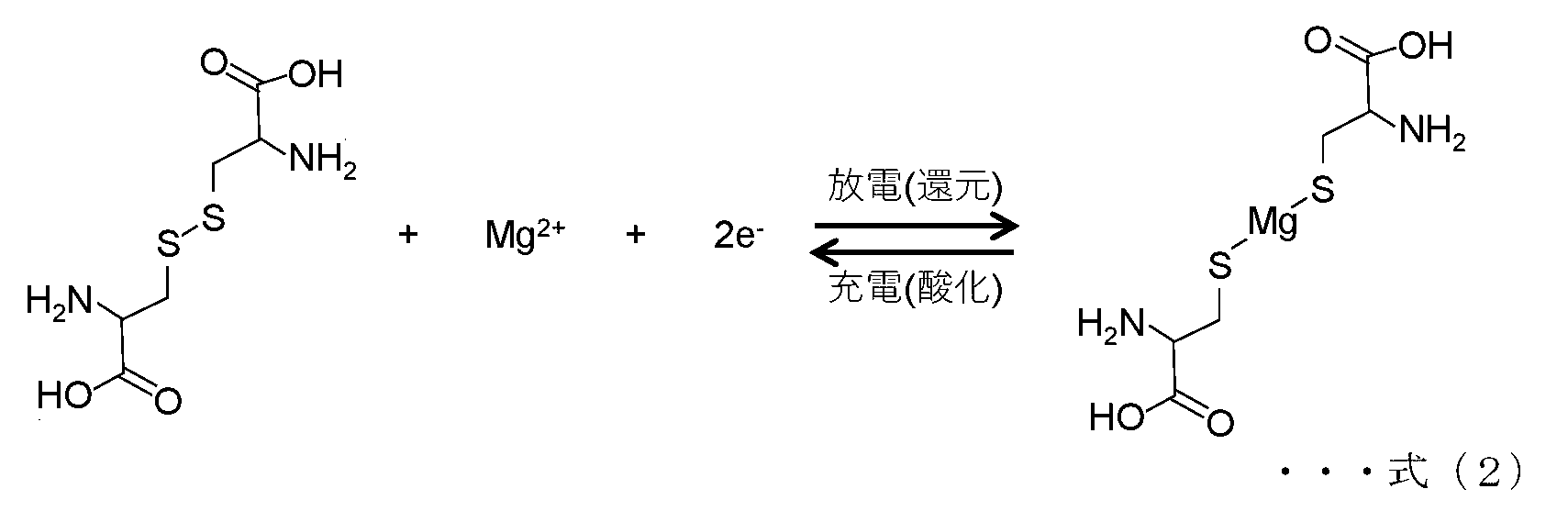
- the charging/discharging reaction at the positive electrode 101 is shown in equation (2).
- the disulfide bonds of cystine contained in the positive electrode 101 are cleaved by electrochemical reduction during discharging, and are regenerated by electrochemical oxidation during charging.
- the reaction progresses in the opposite direction. Specifically, electrochemical oxidation occurs at the positive electrode 101 and the magnesium salt returns to cystine. Electrochemical reduction occurs at the negative electrode 103, and the magnesium ions return to magnesium.
- the cystine contained in the positive electrode 101 may be in a polymerized state.
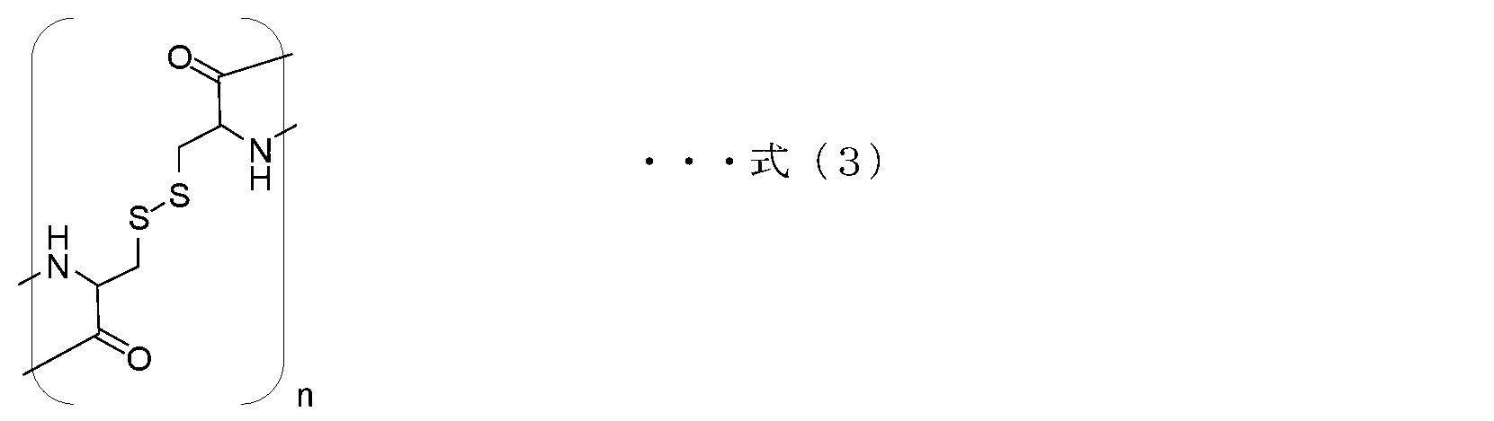
- Examples of polymerized cystine include the polymer shown in formula (3).
- the positive electrode 101 contains a polymer containing a repeating unit represented by formula (4) as polymerized cystine shown in formula (3).
- the positive electrode 101 can be expected to have excellent stability with little deterioration over a long period of time.
- the molecular weight of the cystine polymer compound is preferably 10,000 or more, more preferably 100,000 or more.
- the theoretical electromotive force is approximately 2.5 V when cystine is used as the positive electrode active material and Mg is used as the negative electrode active material.
- the theoretical electromotive force is approximately 3.0 V when cystine is used as the positive electrode active material and Na or Ca is used as the negative electrode active material.
- the secondary battery 100 of this embodiment has a low environmental impact by using cystine as the positive electrode active material, magnesium, sodium, or calcium as the negative electrode active material, and using a nonaqueous electrolyte that does not contain fluorine compounds as the electrolyte. It can be expected to be a good battery.
- the positive electrode 101 can include a positive electrode active material and a conductive aid as constituent elements
- the negative electrode 103 can contain a negative electrode active material and a conductive aid as constituent elements.
- the positive electrode 101 contains at least cystine, which is a positive electrode active material, and can contain a current collector as necessary. Further, the positive electrode 101 is preferably formed of a porous body containing at least one selected from the group consisting of aluminum, copper, and iron, or a nonwoven fabric-like current collector containing carbon. Alternatively, the positive electrode 101 may be formed into a co-continuum in which a plurality of integrated nanostructures have branches to form a three-dimensional network structure.
- the positive electrode 101 is preferably formed without containing a binder.
- a binder is used to stabilize the positive electrode structure (ensuring discharge stability), but the binder has the disadvantage of increasing internal resistance.
- cystine is directly supported on the network structure such as a nonwoven current collector or a co-continuum, so that the positive electrode structure can be stabilized without using a binder. Compared to manufacturing methods using conventional binders, it is expected that the internal resistance of the battery will be reduced.
- the positive electrode 101 containing cystine which is a positive electrode active material
- the positive electrode 101 of the secondary battery configured as described above can fully bring out the potential of cystine, which is the positive electrode active material.
- the positive electrode active material of this embodiment contains at least cystine. Since cystine is derived from living organisms, it has a low environmental impact and is also inexpensive.
- the positive electrode active material is preferably in a polymer state. This is because when the molecular weight of the positive electrode active material is small, it easily dissolves in the electrolytic solution.
- the molecular weight of the positive electrode active material is preferably 10,000 or more, more preferably 100,000 or more.
- Cystine can be obtained, for example, as a commercial product or by known synthesis, and high molecular compounds of cystine can be obtained by known synthesis.
- the positive electrode 101 containing cystine may contain a conductive additive and a binder.
- a conductive additive for example, carbon or the like can be used as the conductive aid.
- the conductive aid include carbon blacks such as Ketjen black and acetylene black, activated carbons, graphites, and carbon fibers.
- carbon with small particles is suitable.
- particles with a particle diameter of 1 ⁇ m or less are desirable. These carbons can be obtained, for example, as commercial products or by known synthesis.
- the binder include polytetrafluoroethylene (PTFE), polyvinylidene fluoride (PVDF), styrene butadiene rubber, ethylene propylene diene rubber, and natural rubber.
- cystine powder which is a positive electrode active material
- a conductive additive and a binder are mixed together, and this mixture is bonded to a conductive material, similar to the conventional method for producing a positive electrode. Then, the positive electrode 101 may be prepared.
- the current collector is a porous body containing at least one selected from the group consisting of aluminum, copper, and iron, or a nonwoven fabric containing carbon. may directly support the positive electrode active material.
- the porous body or nonwoven fabric-like current collector described above can be obtained, for example, as a commercial product.
- a three-dimensional network structure co-continuum in which multiple nanostructures are integrated by non-covalent bonds may directly support the positive electrode active material without using a binder.
- the co-continuum has a deformable bonding portion between the nanostructures, and is an integral structure having elasticity.
- the co-continuum preferably has an average pore diameter of 0.1 to 50 ⁇ m.
- the nanostructure is a nanosheet or nanofiber, and has electrical conductivity. This nanosheet is, for example, graphene.
- Nanofibers are, for example, iron oxide, manganese oxide, silicon or carbonized cellulose. Nanofibers are fibrous substances with a diameter of 1 nm to 1 ⁇ m and a length 100 times or more the diameter.
- carbonized cellulose can be produced by heating and carbonizing a gel in which cellulose nanofibers are dispersed in an inert gas atmosphere.
- the co-continuum can be produced by drying in vacuum a frozen body obtained by freezing a sol or gel in which nanostructures such as nanosheets and nanofibers are dispersed.
- the dispersion medium of the sol is aqueous such as water, carboxylic acid, methanol, ethanol, propanol, n-butanol, isobutanol, n-butylamine, dodecane, unsaturated fatty acid, ethylene glycol, heptane, hexadecane, Organic systems such as isoamyl alcohol, octanol, isopropanol, acetone or glycerin.
- the dispersion medium of the sol may be a mixture of two or more types selected from these organic systems.
- the dispersion medium of the gel is aqueous such as water (H 2 O), carboxylic acid, methanol (CH 3 OH), ethanol (C 2 H 5 OH), propanol (C 3 H 7 OH), Organic systems such as n-butanol, isobutanol, n-butylamine, dodecane, unsaturated fatty acids, ethylene glycol, heptane, hexadecane, isoamyl alcohol, octanol, isopropanol, acetone or glycerin.
- the gel dispersion medium may be a mixture of two or more types selected from these aqueous or organic types.
- the degree of vacuum in the drying step varies depending on the dispersion medium used, but is not particularly limited as long as the degree of vacuum allows the dispersion medium to sublimate.
- the degree of vacuum is preferably 1.0 ⁇ 10 ⁇ 6 to 1.0 ⁇ 10 ⁇ 2 Pa.
- heat may be applied using a heater or the like during drying.
- This co-continuum can have a larger specific surface area than commercially available conductive porous bodies or non-woven fabric current collectors. The specific surface area of this co-continuum is preferably 200 m 2 /g or more.
- the method of supporting the positive electrode active material on the above porous body or nonwoven current collector or co-continuum includes physical methods such as vapor deposition, sputtering, planetary ball mill, etc. There are a method of immersing a body or a co-continuum in a liquid in which a positive electrode active material is dissolved and drying it, a chemical method such as a sol-gel method, or a known method.
- a chemical method such as a sol-gel method, or a known method.
- the porous or nonwoven current collector or co-continuum described above is immersed in a liquid in which the positive electrode active material is dissolved, and then the liquid in which the positive electrode active material is dissolved is immersed in the liquid in which the positive electrode active material is dissolved.
- a preferred method is to support the positive electrode active material by drying the co-continuous pair immersed in water.
- the solvent for dissolving the positive electrode active material is an aqueous solvent such as water, or tetrahydrofuran (THF), tetrahydropran (THP), dioxane, diethyl ether, N-methyl-2-pyrrolidone (NMP), or hexamethyl.
- HMPA phosphoric acid amide
- TMU tetramethylurea
- DMAc dimethylacetamide
- DMF dimethylformaldehyde
- DMSO dimethylsulfoxide
- m-cresol chloroform.
- the solvent may be a mixture of two or more selected from these aqueous or organic solvents.
- the reaction represented by formula (2) proceeds on the surface of the positive electrode 101, it is preferable to generate a large amount of reaction sites inside the positive electrode 101.
- the positive electrode 101 molded using the porous material, non-woven fabric-like current collector, or co-continuum can secure a large amount of reaction sites and solve the conventional problems described above. It becomes possible to increase the discharge capacity.
- the co-continuum has a high bulk density and can support a larger amount of positive electrode active material, thereby increasing the efficiency of the battery.
- the secondary battery 100 of this embodiment contains at least magnesium (Mg), sodium (Na), or calcium (Ca) as a negative electrode active material.
- This negative electrode active material may contain magnesium (Mg), sodium (Na), or calcium (Ca) as a main component.
- negative electrode active materials include lithium (Li), zinc (Zn), aluminum (Al), iron (Fe), tin (Sn), and carbon (C). ) may be an alloy containing at least one component selected from the group.
- the secondary battery 100 of this embodiment includes a non-aqueous electrolyte as the electrolyte 102.
- This non-aqueous electrolyte is a solution containing an electrolyte that allows movement of magnesium ions (Mg 2+ ), sodium ions (Na + ), or calcium ions (Ca 2+ ).
- the non-aqueous electrolyte uses an organic solvent as a main solvent, and may also contain, for example, water in addition to the organic solvent.
- an electrolytic solution in which a magnesium salt, sodium salt, or calcium salt is dissolved in an organic solvent can be used as the non-aqueous electrolytic solution.
- organic solvents examples include dimethyl carbonate (DMC), methylethyl carbonate (MEC), methylpropyl carbonate (MPC), methylisopropyl carbonate (MIPC), methylbutyl carbonate (MBC), diethyl carbonate (DEC), and ethylpropyl carbonate (EPC).
- DMC dimethyl carbonate
- MEC methylethyl carbonate
- MPC methylpropyl carbonate
- MIPC methylisopropyl carbonate
- MMC methylbutyl carbonate
- DEC diethyl carbonate
- EPC ethylpropyl carbonate
- EIPC ethyl isopropyl carbonate
- EBC ethyl butyl carbonate
- DPC dipropyl carbonate
- DIPC diisopropyl carbonate
- DB dibutyl carbonate
- EC ethylene carbonate
- PC propylene carbonate
- 1,2-carbonate Carbonate solvents such as butylene (1,2-BC)
- ether solvents such as 1,2-dimethoxyethane (DME) and tetraethylene glycol dimethyl ether (TEGDME)
- lactone solvents such as ⁇ -butyrotactone (GBL)
- GBL ⁇ -butyrotactone
- DMSO dimethyl sulfoxide
- X is preferably Cl, Br, I, ClO 4 , AlCl, or N(CN) 2 which is not a fluorine compound. Further, as X, a metal salt obtained by mixing two or more of these metal salts can be used.
- the electrolyte 102 may be in any form such as liquid, cream, gel, or solid.
- the secondary battery 100 of this embodiment can include structural members such as a separator and a battery case, and other elements required for a secondary battery.
- Conventionally known elements can be used as these other elements, but from the viewpoint of environmental load and waste disposal, it is preferable that they do not contain harmful substances, precious metals, etc. Furthermore, it is more preferable that these other elements are biologically derived and biodegradable materials.
- the secondary battery 100 of this embodiment includes at least the positive electrode 101, the negative electrode 103, and the electrolyte 102. As illustrated in FIG. 1, an electrolyte 102 is placed between the positive electrode 101 and the negative electrode 103 so as to be in contact with the positive electrode 101 and the negative electrode 103.
- the secondary battery 100 having such a configuration can be prepared in the same manner as a conventional secondary battery.
- the secondary battery 100 includes a positive electrode 101 containing a positive electrode active material containing cystine as described above, a negative electrode 103 containing magnesium (Mg), sodium (Na), or calcium (Ca), and a positive electrode 101 and a negative electrode 103.
- a positive electrode 101 containing a positive electrode active material containing cystine as described above
- a negative electrode 103 containing magnesium (Mg), sodium (Na), or calcium (Ca)
- Mg magnesium
- Na sodium
- Ca calcium
- Each element of the electrolyte 102 which is placed in contact with the electrolyte 102, may be assembled according to conventional techniques.
- the positive electrode 101 may include a conductive additive and a binder.
- a coin-shaped secondary battery can be manufactured, for example.
- FIG. 2 is a schematic cross-sectional view showing the structure of the coin-type secondary battery 100a.
- the positive electrode 101 is placed in a circular positive electrode case 201 .
- a separator (not shown) is placed on the positive electrode 101, and a non-aqueous electrolyte is injected as the electrolyte 102 into the placed separator.
- a propylene gasket 203 is fitted into the outer peripheral edge of the circular negative electrode case 202.
- the negative electrode 103 is placed on the electrolyte 102, and the negative electrode case 202 fitted with the propylene gasket 203 is placed over the positive electrode case 201.
- the propylene gasket 203 comes into contact with the inner edge of the positive electrode case 201, and the negative electrode case 202 is placed over the positive electrode case 201 so that the positive electrode 101 and the negative electrode 103 do not come into contact with each other.
- the coin-shaped secondary battery 100a including the propylene gasket 203.
- the illustrated coin-type secondary battery 100a uses cystine as a positive electrode active material. Therefore, unlike an air battery that uses oxygen in the air as a positive electrode active material, the positive electrode case 201 of this embodiment does not need to be provided with an air intake port. That is, in this embodiment, a sealed battery can be manufactured. Therefore, the coin-type secondary battery 100a of this embodiment can be stored for a long period of time without the electrolytic solution volatilizing from the air intake port.
- the secondary battery 100 used in each example uses each of magnesium (Mg), sodium (Na), and calcium (Ca) for the negative electrode 103.
- the secondary battery 100 uses each of magnesium (Mg), sodium (Na), and calcium (Ca) in the negative electrode 103, and the electrolyte 102 contains each of Mg(ClO 4 ) 2 , NaClO 4 and Ca(ClO 4 ) 2 .
- Use a propylene carbonate solution containing It should be noted that the present invention is not limited to what is shown in the following examples, but can be implemented with appropriate changes.
- a coin-type secondary battery 100a shown in FIG. 2 was manufactured in the following procedure. Furthermore, cystine was used as a positive electrode active material. Magnesium (Mg) foil, sodium (Na) foil, and calcium (Ca) foil were used as negative electrode active materials. 0.5 mol/L of Mg(ClO 4 ) 2 , NaClO 4 and Propylene carbonate solutions each containing Ca(ClO 4 ) 2 were used.
- Cystine powder (Tokyo Kasei Kogyo Co., Ltd.), Ketjen black powder (EC600JD, Lion Specialty Chemicals), and polytetrafluoroethylene (PTFE) powder were mixed in a weight ratio of 80:10:10 using a crusher. The mixture was sufficiently pulverized and mixed, and then roll-molded to produce a sheet-like electrode (thickness: 0.5 mm).
- a positive electrode 101 was obtained by cutting out a circle with a diameter of 16 mm from this sheet-like electrode and pressing it onto a copper mesh.
- a negative electrode 103 was obtained by cutting out a circle with a diameter of 16 mm and joining each of these pieces to a copper foil (Nilaco Co., Ltd.) using an ultrasonic welding machine.
- a coin-type secondary battery 100a shown in FIG. 2 was produced using a coin battery case (Hosensha).
- a cellulose-based separator (Nippon Kokoshi Kogyo Co., Ltd.) cut out to a diameter of 18 mm was placed on the positive electrode case 201 in which the positive electrode 101 prepared by the above method was installed, and Mg(ClO 4 ) 2 , NaClO 4 was placed on the placed separator.
- a propylene carbonate solution (Kishida Chemical Co., Ltd.) containing each of Ca(ClO 4 ) 2 and Ca(ClO 4 ) 2 is injected as the electrolyte 102.
- the above negative electrode 103 is placed on top of the electrolyte 102, the negative electrode case 202 is placed over the positive electrode case 201, and the peripheral edges of the positive electrode case 201 and negative electrode case 202 are caulked using a coin cell crimping machine, thereby forming a coin-shaped double holder including a propylene gasket 203.
- a secondary battery 100a was obtained.
- the battery performance of the secondary battery 100 prepared according to the above procedure was measured.
- a charge/discharge measurement system manufactured by Bio Logic
- the battery voltage was determined to be 0.0 mA/cm 2 from the open circuit voltage.
- the discharge voltage was measured until it decreased to 10V.
- the battery discharge test was conducted under normal living conditions. The discharge capacity was expressed as a value per unit weight of the positive electrode active material (cystine) (mAh/g).
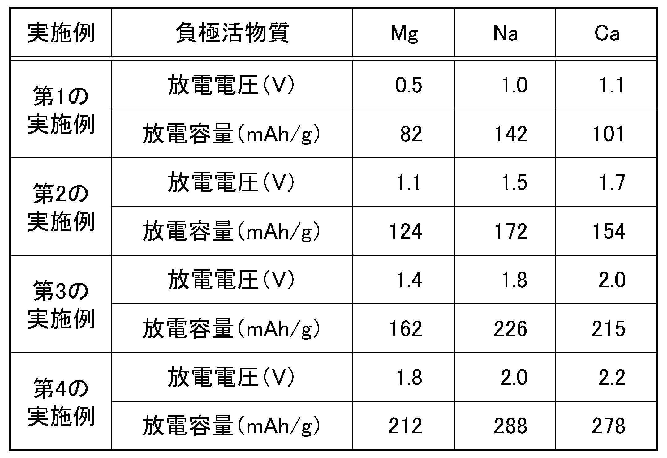
- Table 1 shows the discharge capacity and discharge voltage of the secondary battery of the first example.
- the discharge voltages of the first example of the battery using magnesium (Mg), sodium (Na), and calcium (Ca) in the negative electrode 103 were 0.5V, 1.0V, and 1V, respectively.
- the discharge capacities were 82 mAh/g, 142 mAh/g, and 101 mAh/g, respectively.
- the discharge voltage is defined as the discharge voltage when the discharge capacity is 1/2 of the total discharge capacity.
- a coin-type secondary battery 100a shown in FIG. 2 was manufactured using the following procedure. Further, cystine was used as a positive electrode active material, and the positive electrode active material was prepared by supporting it on a nonwoven fabric-like current collector (carbon felt) containing carbon. Magnesium (Mg) foil, sodium (Na) foil, and calcium (Ca) foil were used as negative electrode active materials. 0.5 mol/L of Mg(ClO 4 ) 2 , NaClO 4 and A propylene carbonate solution containing each of Ca(ClO 4 ) 2 was used.
- the battery evaluation method is the same as in the first example.
- a negative electrode 103 was obtained by cutting out a circle with a diameter of 16 mm and joining each of these pieces to a copper foil (Nilaco Co., Ltd.) using an ultrasonic welder.
- a coin-type secondary battery 100a shown in FIG. 2 was produced using a coin battery case (Hosensha).
- a cellulose-based separator (Nippon Kokoshi Kogyo Co., Ltd.) cut out to a diameter of 18 mm was placed on the positive electrode case 201 in which the positive electrode 101 prepared by the above method was installed, and Mg(ClO 4 ) 2 , NaClO 4 was placed on the placed separator.
- a propylene carbonate solution (Kishida Chemical Co., Ltd.) containing each of Ca(ClO 4 ) 2 and Ca(ClO 4 ) 2 is injected as the electrolyte 102.
- the above negative electrode 103 is placed on top of the electrolyte 102, the negative electrode case 202 is placed over the positive electrode case 201, and the peripheral edges of the positive electrode case 201 and negative electrode case 202 are caulked using a coin cell crimping machine, thereby forming a coin-shaped double holder including a propylene gasket 203.
- a secondary battery 100a was obtained.
- Table 1 shows the discharge capacity and discharge voltage of the secondary battery of the second example.
- the discharge capacity of the second example of the battery using magnesium (Mg) for the negative electrode 103 was 124 mAh/g, which was a larger value than the first example.
- the discharge capacity of the battery using sodium (Na) and calcium (Ca) as the negative electrode was also larger than that of the first example.
- the discharge voltage of the second example is higher than the discharge voltage of the first example. That is, in the second example, the overvoltage was reduced more than in the first example, and the energy efficiency of discharge could be improved.
- a coin-type secondary battery 100a shown in FIG. 2 was manufactured using the following procedure.
- cystine was used as a positive electrode active material and was prepared by being supported on a co-continuum.
- Magnesium (Mg) foil, sodium (Na) foil, and calcium (Ca) foil were used as negative electrode active materials.
- 0.5 mol/L of Mg(ClO 4 ) 2 , NaClO 4 and A propylene carbonate solution containing each of Ca(ClO 4 ) 2 was used.
- the battery evaluation method is the same as in the first example and the second example.
- the production of the above-mentioned co-continuum involves first placing a bacterial cellulose gel produced by the acetic acid bacterium Acetobacter The gel was completely frozen. Next, the frozen bacterial cellulose gel was taken out into an eggplant flask and dried in a vacuum of 10 Pa or less using a freeze dryer (Tokyo Rika Kikai Co., Ltd.). Thereafter, a co-continuum was manufactured by carbonizing it by firing at 1200° C. for 2 hours in a nitrogen atmosphere.
- a negative electrode 103 was obtained by cutting out a circle with a diameter of 16 mm and joining each of these pieces to a copper foil (Nilaco Co., Ltd.) using an ultrasonic welding machine.
- a coin-type secondary battery 100a shown in FIG. 2 was produced using a coin battery case (Hosensha).
- a cellulose separator cut out to a diameter of 18 mm was placed on the positive electrode case 201 in which the positive electrode 101 prepared by the above method was installed, and Mg(ClO 4 ) 2 , NaClO 4 and A propylene carbonate solution (Kishida Chemical Co., Ltd.) containing each of Ca(ClO 4 ) 2 is injected as the electrolyte 102.
- the above negative electrode 103 is placed on top of the electrolyte 102, the negative electrode case 202 is placed over the positive electrode case 201, and the peripheral edges of the positive electrode case 201 and negative electrode case 202 are caulked using a coin cell crimping machine, thereby forming a coin-shaped double holder including a propylene gasket 203.
- a secondary battery 100a was obtained.
- Table 1 shows the discharge capacity and discharge voltage of the secondary battery of the third example.
- the discharge capacity of the third example of the battery using magnesium (Mg) for the negative electrode 103 was 162 mAh/g, which is a larger value than the first example and the second example. there were.
- the discharge capacities were larger than those in the first example and the second example.
- the discharge voltage of the third example is higher than the discharge voltage of the first example and the second example. That is, in the third example, the overvoltage was reduced more than in the first and second examples, and it was possible to achieve an improvement in the energy efficiency of discharge.
- a coin-shaped secondary battery 100a shown in FIG. 2 was manufactured using the following procedure.
- a compound obtained by polymerizing cystine was used as a positive electrode active material, and was prepared by supporting it on a co-continuum.
- Magnesium (Mg) foil, sodium (Na) foil, and calcium (Ca) foil were used as negative electrode active materials.
- 0.5 mol/L of Mg(ClO 4 ) 2 , NaClO 4 and A propylene carbonate solution containing each of Ca(ClO 4 ) 2 was used.
- the battery evaluation method is the same as in the first example, second example, and third example. However, the measurement of the charge/discharge test was carried out until the discharge voltage decreased to 0.10V.
- the production of the above-mentioned cystine-polymerized compound starts with adding ethyl acetate (Tokyo Kasei Kogyo Co., Ltd.) to cystine powder (Tokyo Kasei Kogyo Co., Ltd.) and (1S)-(-)- ⁇ -pinene in an Ar atmosphere. (Tokyo Kasei Kogyo Co., Ltd.) and bis(trichloromethyl) carbonate (Tokyo Kasei Kogyo Co., Ltd.) were added, and after stirring at 90°C for 3 hours, insoluble matter in the solution was filtered off. Hexane was added to the solution, and after stirring for 30 minutes, the precipitated solid was collected by suction filtration.
- cystine N-carboxy anhydride NCA
- dichloromethane Tokyo Kasei Kogyo Co., Ltd.
- butylamine Tokyo Kasei Kogyo Co., Ltd.
- dichloromethane Tokyo Kasei Kogyo Co., Ltd.
- the production of the above-mentioned co-continuum involves first placing a bacterial cellulose gel produced by the acetic acid bacterium Acetobacter The gel was completely frozen. Next, the frozen bacterial cellulose gel was taken out into an eggplant flask and dried in a vacuum of 10 Pa or less using a freeze dryer (Tokyo Rika Kikai Co., Ltd.). Thereafter, a co-continuum was manufactured by carbonizing it by firing at 1200° C. for 2 hours in a nitrogen atmosphere.
- a negative electrode 103 was obtained by cutting out a circle with a diameter of 16 mm and joining each of these pieces to a copper foil (Nilaco Co., Ltd.) using an ultrasonic welding machine.
- a coin-type secondary battery 100a shown in FIG. 2 was produced using a coin battery case (Hosensha).
- a cellulose separator cut out to a diameter of 18 mm was placed on the positive electrode case 201 in which the positive electrode 101 prepared by the above method was installed, and Mg(ClO 4 ) 2 , NaClO 4 and A propylene carbonate solution (Kishida Chemical Co., Ltd.) containing each of Ca(ClO 4 ) 2 is injected as the electrolyte 102 .
- the above negative electrode 103 is placed on top of the electrolyte 102, the negative electrode case 202 is placed over the positive electrode case 201, and the peripheral edges of the positive electrode case 201 and negative electrode case 202 are caulked using a coin cell crimping machine, thereby forming a coin-shaped double holder including a propylene gasket 203.
- a secondary battery 100a was obtained.
- Table 1 shows the discharge capacity and discharge voltage of the secondary battery of the fourth example.
- the discharge capacity of the fourth example in the battery using magnesium (Mg) for the negative electrode was 212 mAh/g
- the discharge capacity of the battery using magnesium (Mg) for the negative electrode was 212 mAh/g.
- the value was larger than the example.
- the discharge capacities of the batteries using sodium (Na) and calcium (Ca) as negative electrodes were also larger than those of the first, second, and third examples.
- the discharge voltage of the fourth example is higher than those of the first example, the second example, and the third example. That is, in the fourth example, the overvoltage was reduced more than in the first, second, and third examples, and it was possible to improve the energy efficiency of discharge.
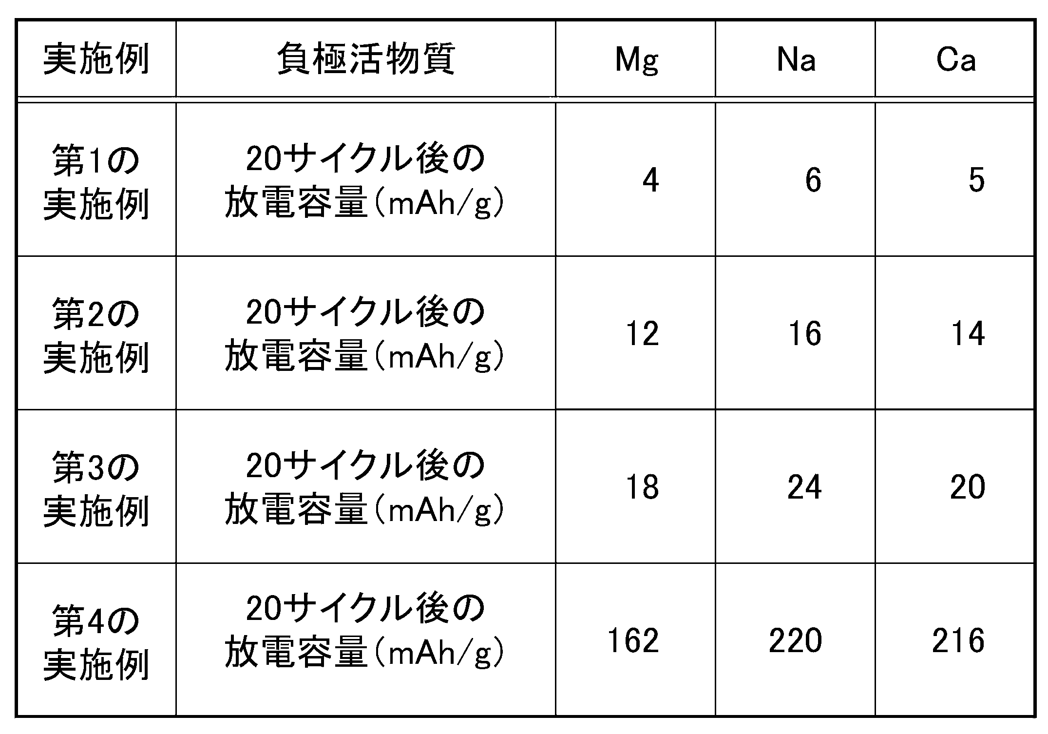
- the discharge capacity of the fourth example after 20 cycles was 162 mAh/g, which is a larger value than the first example, the second example, and the third example. there were.
- the secondary battery 100 of this embodiment is a sealed battery that does not require an air intake port, unlike an air battery. Therefore, the secondary battery 100 of this embodiment can be stored for a long period of time without the electrolytic solution volatilizing from the air intake port.
- the secondary battery 100 of this embodiment can be effectively used as a new driving source for various electronic devices such as small devices, sensors, and mobile devices.
Landscapes
- Chemical & Material Sciences (AREA)
- Chemical Kinetics & Catalysis (AREA)
- Electrochemistry (AREA)
- General Chemical & Material Sciences (AREA)
- Engineering & Computer Science (AREA)
- Materials Engineering (AREA)
- Manufacturing & Machinery (AREA)
- Battery Electrode And Active Subsutance (AREA)
Abstract
Description
図1は、本発明の実施の形態における二次電池100の構成を示す構成図である。この二次電池100は、シスチンを含む正極101と、マグネシウム、ナトリウムまたはカルシウムを含む負極103と、正極101と負極103との間に配置された電解質102と、を備える。電解質102は、非水系電解液を用いることが好ましい。以下に説明する本実施形態では、負極103にマグネシウム、電解質102に非水系電解液を用いた場合を一例として説明するが、これに限定されない。


正極101は、正極活物質であるシスチンを少なくとも含み、必要に応じて集電体を含むことができる。また、正極101は、アルミニウム、銅および鉄からなる群より選択される少なくとも1つを含む多孔質体またはカーボンを含む不織布状の集電体に形成されることが好ましい。あるいは正極101は、一体とされた複数のナノ構造体が分岐を有することで三次元ネットワーク構造とされた共連続体に形成されても良い。
本実施形態の正極活物質は、少なくともシスチンを含む。シスチンは生物由来であるため低環境負荷であり、さらに、安価である。
別の実施の形態において、シスチンを含む正極101に、導電助剤と結着剤を含んでもよい。導電助剤には、例えばカーボンなどを用いることができる。具体的に導電助剤は、ケッチェンブラック、アセチレンブラックなどのカーボンブラック類、活性炭類、グラファイト類またはカーボン繊維類などを挙げることができる。正極101中で反応部位を十分確保するために、カーボンは粒子が小さいものが適している。具体的には、粒子径が1μm以下のものが望ましい。これらのカーボンは、例えば市販品として、または公知の合成により入手することが可能である。結着剤は、具体的には、ポリテトラフルオロエチレン(PTFE)、ポリフッ化ビニリデン(PVDF)、スチレンブタジエンゴム、エチレンプロピレンジエンゴムまたは天然ゴムなどを例として挙げることができる。
本実施形態において、アルミニウム、銅および鉄からなる群より選択される少なくとも1つを含む多孔質体、またはカーボンを含む不織布状の集電体は、正極活物質を直接担持してもよい。上記の多孔質体または不織布状の集電体は、例えば市販品として入手することが可能である。
本実施形態の二次電池100は、負極活物質として、少なくともマグネシウム(Mg)、ナトリウム(Na)またはカルシウム(Ca)を含む。この負極活物質は、主成分としてマグネシウム(Mg)、ナトリウム(Na)またはカルシウム(Ca)を含めばよい。負極活物質は、マグネシウム(Mg)、ナトリウム(Na)またはカルシウム(Ca)のほか、リチウム(Li)、亜鉛(Zn)、アルミニウム(Al)、鉄(Fe)、錫(Sn)およびカーボン(C)からなら群から選ばれる少なくとも1つの成分を含む合金であっても良い。
本実施形態の二次電池100は、電解質102として非水系電解液を含む。この非水系電解液は、マグネシウムイオン(Mg2+)、ナトリウムイオン(Na+)またはカルシウムイオン(Ca2+)の移動が可能な電解質を含む溶液である。非水系電解液は、主溶媒として有機溶媒を用い、有機溶媒以外に、例えば、水を含んでもよい。非水系電解液は、有機溶媒にマグネシウム塩またはナトリウム塩またはカルシウム塩を溶解させた電解液を用いることができる。有機溶媒は、例えば、炭酸ジメチル(DMC)、炭酸メチルエチル(MEC)、炭酸メチルプロピル(MPC)、炭酸メチルイソプロピル(MIPC)、炭酸メチルブチル(MBC)、炭酸ジエチル(DEC)、炭酸エチルプロピル(EPC)、炭酸エチルイソプロピル(EIPC)、炭酸エチルブチル(EBC)、炭酸ジプロピル(DPC)、炭酸ジイソプロピル(DIPC)、炭酸ジブチル(DBC)、炭酸エチレン(EC)、炭酸プロピレン(PC)、炭酸1,2-ブチレン(1,2-BC)などの炭酸エステル系溶媒、1,2-ジメトキシエタン(DME)、テトラエチレングリコールジメチルエーテル(TEGDME)などのエーテル系溶媒、γ-ブチロタクトン(GBL)などのラクトン系溶媒、および、ジメチルスルホキシド(DMSO)などのスルホキシド系溶媒からなる群より少なくとも1つが選ばれる。マグネシウム塩、ナトリウム塩及びカルシウム塩は、それぞれMg-X2、Na-X及びCa-X2で表される。ここで、Xは例えば、Cl、Br、I、BF4、PF6、CF3SO3、ClO4、CF3CO2、AsF6、SbF6、AlCl4、N(CF3SO2)2、N(CF3CF2SO2)2、PF3(C2F5)3、N(FSO2)2、N(FSO2)(CF3SO2)、N(CF3CF2SO2)2、N(C2F4S2O4)、N(C3F6S2O4)、N(CN)2、N(CF3SO2)(CF3CO)またはR1FBF3(但し、R1F=n-CmF2m+1、m=1~4の自然数)およびR2BF3(但し、R2=n-CpH2p+1、p=1~5の自然数)を挙げることができる。Xは、環境負荷の観点からフッ素化合物ではない、Cl、Br、I、ClO4、AlCl、N(CN)2が好ましいましい。更にXは、これらの中から二種類以上を混合した金属塩を使用することができる。
本実施形態の二次電池100は、上記構成要素に加え、セパレータ、電池ケースなどの構造部材、その他二次電池に要求される要素を含むことができる。これらの他の要素は、従来公知のものが使用できるが、環境負荷及び廃棄処理の観点から、有害物質、貴金属等を含まないことが好ましい。更に、これらの他の要素は、生物由来、生分解性材料であることがより好適である。
本実施形態の二次電池100は、上述した通り、少なくとも正極101、負極103及び電解質102を含む。図1に例示されるように、正極101と負極103との間に、正極101および負極103に接するように電解質102が配置される。このような構成の二次電池100は、従来型の二次電池と同様に調製することができる。
以下に本実施形態に係る二次電池100の実施例を詳細に説明する。各実施例で用いる二次電池100は、負極103に、マグネシウム(Mg)、ナトリウム(Na)およびカルシウム(Ca)のそれぞれを用いる。負極103にマグネシウム(Mg)、ナトリウム(Na)およびカルシウム(Ca)のそれぞれを用いる二次電池100は、電解質102に、Mg(ClO4)2、NaClO4およびCa(ClO4)2のそれぞれを含む炭酸プロピレン溶液を用いる。なお、本発明は下記の実施例に示したものに限定されるものではなく、適宜変更して実施できるものである。
第1の実施例では、図2に示すコイン型二次電池100aを以下の手順で作製した。また、正極活物質としてシスチンを使用した。負極活物資として、マグネシウム(Mg)箔、ナトリウム(Na)箔およびカルシウム(Ca)箔のそれぞれを使用した。マグネシウム(Mg)箔、ナトリウム(Na)箔およびカルシウム(Ca)箔のそれぞれを使用したコイン型二次電池100aに、電解質102として、0.5mol/LのMg(ClO4)2、NaClO4およびCa(ClO4)2をそれぞれ含む炭酸プロピレン溶液を使用した。
シスチン粉末(東京化成工業株式会社)、ケッチェンブラック粉末(EC600JD、ライオン・スペシャリティ・ケミカルズ社)、ポリテトラフルオロエチレン(PTFE)粉末を、80:10:10の重量比で擂潰機を用いて十分に粉砕混合し、ロール成形して、シート状電極(厚さ:0.5mm)を作製した。このシート状電極を直径16mmの円形に切り抜き、銅メッシュ上にプレスすることにより、正極101を得た。
マグネシウム(Mg)箔(厚さ150μm、株式会社ニラコ)、ナトリウム(Na)箔(厚さ150μm、Sigma-Aldrich Co.LLC)およびカルシウム(Ca)箔(厚さ150μm、株式会社ニラコ)のそれぞれを、直径16mmの円形に切り抜き、これらのそれぞれを、超音波溶接機を使用して銅箔(株式会社ニラコ)に接合させることにより、負極103を得た。
コイン電池用ケース(宝泉社)を使用して、図2に示すコイン型二次電池100aを作製した。
以上の手順で調整した二次電池100の電池性能を測定した。電池のサイクル試験は、充放電測定システム(Bio Logic社製)を用いて、正極101の有効面積当たりの電流密度で1.0mA/cm2を通電し、開回路電圧から電池電圧が、0.10Vに低下するまで放電電圧の測定を行った。電池の放電試験は、通常の生活環境下で行った。放電容量は、正極活物質(シスチン)の単位重量当たりの値(mAh/g)で表した。
第2の実施例では、図2に示すコイン型二次電池100aを以下の手順で作製した。また、正極活物質としてシスチンを使用し、正極活物質を、カーボンを含む不織布状の集電体(カーボンフェルト)に担持して調製した。負極活物資として、マグネシウム(Mg)箔、ナトリウム(Na)箔およびカルシウム(Ca)箔のそれぞれを使用した。マグネシウム(Mg)箔、ナトリウム(Na)箔およびカルシウム(Ca)箔のそれぞれを使用したコイン型二次電池100aに、電解質102として、0.5mol/LのMg(ClO4)2、NaClO4およびCa(ClO4)2のそれぞれを含む炭酸プロピレン溶液を使用した。
シスチン粉末(東京化成工業株式会社)を1.0Mの塩酸(東京化成工業株式会社)で溶解した液体に、カーボンフェルト(東洋紡株式会社)を浸漬させた。このカーボンフェルトを80℃の真空乾燥機で30分乾燥させることで、シスチンをカーボンフェルトに析出させた後に、純水で洗浄した。そして、このシスチン含有カーボンフェルトを直径16mmの円形に切り抜き、正極101を得た。
マグネシウム(Mg)箔(厚さ150μm、株式会社ニラコ)、ナトリウム(Na)箔(厚さ150μm、Sigma-Aldrich Co.LLC)、およびカルシウム(Ca)箔(厚さ150μm、株式会社ニラコ)のそれぞれを、直径16mmの円形に切り抜き、これらのそれぞれを、超音波溶接機を使用して銅箔(株式会社ニラコ)に接合させることにより、負極103を得た。
コイン電池用ケース(宝泉社)を使用して、図2に示すコイン型二次電池100aを作製した。
第2の実施例の二次電池の放電容量及び放電電圧を、表1に示す。表1に示すように、負極103にマグネシウム(Mg)を用いた電池における第2の実施例の放電容量は124mAh/gを示し、第1の実施例よりも大きい値であった。負極にナトリウム(Na)およびカルシウム(Ca)をそれぞれ用いた電池においても、第1の実施例の放電容量よりも大きい値であった。
第3の実施例では、図2に示すコイン型二次電池100aを以下の手順で作製した。また、正極活物質としてシスチンを使用し、共連続体に担持して調製した。負極活物資として、マグネシウム(Mg)箔、ナトリウム(Na)箔およびカルシウム(Ca)箔のそれぞれを使用した。マグネシウム(Mg)箔、ナトリウム(Na)箔およびカルシウム(Ca)箔のそれぞれを使用したコイン型二次電池100aに、電解質102として、0.5mol/LのMg(ClO4)2、NaClO4およびCa(ClO4)2のそれぞれを含む炭酸プロピレン溶液を使用した。
シスチン粉末(東京化成工業株式会社)を1.0Mの塩酸(東京化成工業株式会社)で溶解した液体に、共連続体を浸漬させた。この共連続体を80℃の真空乾燥機で30分乾燥させることで、シスチンを共連続体に析出させた後に、純水で洗浄した。そして、このシスチン含有共連続体を、直径16mmの円形に切り抜き、正極101を得た。
マグネシウム(Mg)箔(厚さ150μm、株式会社ニラコ)、ナトリウム(Na)箔(厚さ150μm、Sigma-Aldrich Co.LLC)およびカルシウム(Ca)箔(厚さ150μm、株式会社ニラコ)のそれぞれを、直径16mmの円形に切り抜き、これらのそれぞれを、超音波溶接機を使用して銅箔(株式会社ニラコ)に接合させることにより、負極103を得た。
コイン電池用ケース(宝泉社)を使用して、図2に示すコイン型二次電池100aを作製した。
第3の実施例の二次電池の放電容量及び放電電圧を、表1に示す。表1に示すように、負極103にマグネシウム(Mg)を用いた電池における第3の実施例の放電容量は162mAh/gを示し、第1の実施例及び第2の実施例よりも大きい値であった。負極103にナトリウム(Na)およびカルシウム(Ca)をそれぞれ用いた電池においても、第1の実施例及び第2の実施例の放電容量よりも大きい値であった。
第4の実施例では、図2に示すコイン型二次電池100aを以下の手順で作製した。また、正極活物質としてシスチンを高分子化した化合物を使用し、共連続体に担持して調製した。負極活物資として、マグネシウム(Mg)箔、ナトリウム(Na)箔およびカルシウム(Ca)箔のそれぞれを使用した。マグネシウム(Mg)箔、ナトリウム(Na)箔およびカルシウム(Ca)箔のそれぞれを使用したコイン型二次電池100aに、電解質102として、0.5mol/LのMg(ClO4)2、NaClO4およびCa(ClO4)2のそれぞれを含む炭酸プロピレン溶液を使用した。
シスチンを高分子化した化合物をテトラヒドロフラン(THF)(東京化成工業株式会社)で溶解した液体に、共連続体を浸漬させた。この共連続体を80℃の真空乾燥機で30分乾燥させることで、シスチンを高分子化した化合物を共連続体に析出させた。その後、このシスチンを高分子化した化合物含有共連続体を直径16mmの円形に切り抜き、正極101を得た。
マグネシウム(Mg)箔(厚さ150μm、株式会社ニラコ)、ナトリウム(Na)箔(厚さ150μm、Sigma-Aldrich Co.LLC)およびカルシウム(Ca)箔(厚さ150μm、株式会社ニラコ)のそれぞれを、直径16mmの円形に切り抜き、これらのそれぞれを、超音波溶接機を使用して銅箔(株式会社ニラコ)に接合させることにより、負極103を得た。
コイン電池用ケース(宝泉社)を使用して、図2に示すコイン型二次電池100aを作製した。
第4の実施例の二次電池の放電容量及び放電電圧を、表1に示す。表1に示すように、負極にマグネシウム(Mg)を用いた電池における第4の実施例の放電容量は、212mAh/gを示し、第1の実施例、第2の実施例及び第3の実施例よりも大きい値であった。負極にナトリウム(Na)およびカルシウム(Ca)をそれぞれ用いた電池においても、第1の実施例、第2の実施例及び第3の実施例の放電容量よりも大きい値であった。
101:正極
102:電解質
103:負極
201:正極ケース
202:負極ケース
203:プロピレンガスケット
Claims (4)
- シスチンを含む正極と、
マグネシウム、ナトリウムまたはカルシウムを含む負極と、
前記正極と前記負極との間に配置された電解質と、を備える
二次電池。 - 前記正極は、式(1)で表される繰り返し単位を含むポリマーを含む
請求項1に記載の二次電池。

- 前記正極が、アルミニウム、銅および鉄からなる群より選択される少なくとも1つを含む多孔質体またはカーボンを含む不織布状の集電体に形成され、
結着剤を含まない
請求項1に記載の二次電池。 - 前記正極は、一体とされた複数のナノ構造体が分岐を有することで三次元ネットワーク構造とされた共連続体に形成され、
結着剤を含まない
請求項1に記載の二次電池。
Priority Applications (2)
| Application Number | Priority Date | Filing Date | Title |
|---|---|---|---|
| PCT/JP2022/020214 WO2023218638A1 (ja) | 2022-05-13 | 2022-05-13 | 二次電池 |
| JP2024520211A JP7755206B2 (ja) | 2022-05-13 | 2022-05-13 | 二次電池 |
Applications Claiming Priority (1)
| Application Number | Priority Date | Filing Date | Title |
|---|---|---|---|
| PCT/JP2022/020214 WO2023218638A1 (ja) | 2022-05-13 | 2022-05-13 | 二次電池 |
Publications (1)
| Publication Number | Publication Date |
|---|---|
| WO2023218638A1 true WO2023218638A1 (ja) | 2023-11-16 |
Family
ID=88730102
Family Applications (1)
| Application Number | Title | Priority Date | Filing Date |
|---|---|---|---|
| PCT/JP2022/020214 Ceased WO2023218638A1 (ja) | 2022-05-13 | 2022-05-13 | 二次電池 |
Country Status (2)
| Country | Link |
|---|---|
| JP (1) | JP7755206B2 (ja) |
| WO (1) | WO2023218638A1 (ja) |
Citations (2)
| Publication number | Priority date | Publication date | Assignee | Title |
|---|---|---|---|---|
| JPS5586074A (en) * | 1973-03-15 | 1980-06-28 | Hitachi Maxell Ltd | Air cell |
| CN102208599A (zh) * | 2011-05-13 | 2011-10-05 | 北京化工大学 | 一种锂-硫电池正极极片及其制备方法 |
-
2022
- 2022-05-13 WO PCT/JP2022/020214 patent/WO2023218638A1/ja not_active Ceased
- 2022-05-13 JP JP2024520211A patent/JP7755206B2/ja active Active
Patent Citations (2)
| Publication number | Priority date | Publication date | Assignee | Title |
|---|---|---|---|---|
| JPS5586074A (en) * | 1973-03-15 | 1980-06-28 | Hitachi Maxell Ltd | Air cell |
| CN102208599A (zh) * | 2011-05-13 | 2011-10-05 | 北京化工大学 | 一种锂-硫电池正极极片及其制备方法 |
Also Published As
| Publication number | Publication date |
|---|---|
| JP7755206B2 (ja) | 2025-10-16 |
| JPWO2023218638A1 (ja) | 2023-11-16 |
Similar Documents
| Publication | Publication Date | Title |
|---|---|---|
| CA2184792C (en) | Rechargeable lithium battery having an improved cathode and process for the production thereof | |
| JP5516578B2 (ja) | 蓄電デバイス | |
| US9525197B2 (en) | Stable non-aqueous electrolyte promoting ideal reaction process in rechargeable lithium-air batteries | |
| TW200305174A (en) | Material for electrolytic solutions and use thereof | |
| CN107004834A (zh) | 钙基二次电池用电解质和包含该电解质的钙基二次电池 | |
| JP7359156B2 (ja) | 活物質複合体形成用組成物、活物質複合体、および活物質複合体の製造方法 | |
| CN107112503A (zh) | 钙基二次电池及包含该钙基二次电池的蓄电池 | |
| JP2014191915A (ja) | 蓄電デバイス用電極およびそれを用いた蓄電デバイス | |
| JP7769268B2 (ja) | 二次電池 | |
| CN115868070B (zh) | 包含固体有机催化剂的可再充电的非含水锂-空气电池单元 | |
| CN114388793A (zh) | 非水电解质二次电池用负极及包括该负极的非水电解质二次电池 | |
| EP2835859B1 (en) | Electrolyte solution for lithium-air batteries, and lithium-air battery comprising the same | |
| JPWO2013084767A1 (ja) | 重合体およびそれを用いた二次電池 | |
| JP7755206B2 (ja) | 二次電池 | |
| JP7801636B2 (ja) | 二次電池 | |
| JP7817636B2 (ja) | 二次電池 | |
| JP7820672B2 (ja) | 二次電池 | |
| WO2014006973A1 (ja) | 蓄電デバイス用電極、それを用いた蓄電デバイスおよびその製法 | |
| JP7650016B2 (ja) | 二次電池用電極 | |
| JP2015032545A (ja) | 非水電解質二次電池 | |
| JP2011029136A (ja) | 二次電池用電極、二次電池、及び二次電池用電極の製造方法 | |
| WO2024142381A1 (ja) | 二次電池 | |
| EP4636861A1 (en) | Rechargeable zinc-quinone cell | |
| CA2296838C (en) | Method of producing a rechargeable lithium battery having an improved cathode | |
| WO2024166382A1 (ja) | 一次電池 |
Legal Events
| Date | Code | Title | Description |
|---|---|---|---|
| 121 | Ep: the epo has been informed by wipo that ep was designated in this application |
Ref document number: 22941715 Country of ref document: EP Kind code of ref document: A1 |
|
| WWE | Wipo information: entry into national phase |
Ref document number: 2024520211 Country of ref document: JP |
|
| WWE | Wipo information: entry into national phase |
Ref document number: 18863291 Country of ref document: US |
|
| NENP | Non-entry into the national phase |
Ref country code: DE |
|
| 122 | Ep: pct application non-entry in european phase |
Ref document number: 22941715 Country of ref document: EP Kind code of ref document: A1 |