WO2023218615A1 - 処理装置、処理方法及び処理プログラム - Google Patents
処理装置、処理方法及び処理プログラム Download PDFInfo
- Publication number
- WO2023218615A1 WO2023218615A1 PCT/JP2022/020103 JP2022020103W WO2023218615A1 WO 2023218615 A1 WO2023218615 A1 WO 2023218615A1 JP 2022020103 W JP2022020103 W JP 2022020103W WO 2023218615 A1 WO2023218615 A1 WO 2023218615A1
- Authority
- WO
- WIPO (PCT)
- Prior art keywords
- target
- information
- execution
- automatic operation
- unit
- Prior art date
- Legal status (The legal status is an assumption and is not a legal conclusion. Google has not performed a legal analysis and makes no representation as to the accuracy of the status listed.)
- Ceased
Links
Images













Classifications
-
- G—PHYSICS
- G06—COMPUTING OR CALCULATING; COUNTING
- G06F—ELECTRIC DIGITAL DATA PROCESSING
- G06F8/00—Arrangements for software engineering
- G06F8/30—Creation or generation of source code
Definitions
- the present invention relates to a processing device, a processing method, and a processing program.
- RPA Robot Process Automation
- Non-Patent Document 1 There is a method of describing automatic operation procedures in the form of a flowchart scenario (Non-Patent Document 1).
- actions such as "click” and "character string setting” are defined as blocks in a flowchart, and controls are described by connecting them.
- information to be automatically operated is included in each action block.
- Non-Patent Document 2 there is a method of writing automatic operation procedures in a dedicated script language or various programming languages (Non-Patent Document 2).
- control is described using syntax of each language, API (Application Programming Interface)/command, etc., and target information is hard-coded as an argument of the API/command.
- targets that are subject to automatic operation and are susceptible to environmental factors such as system screens, and controls such as how to process them are described as an integrated scenario or rule. .
- the present invention has been made in view of the above, and an object of the present invention is to provide a processing device, a processing method, and a processing program that can reduce the influence of environment changes on modification of scenarios and rules.
- a processing device specifies an automatic operation target displayed on a system screen, and converts the position information and alias of the specified automatic operation target into target information.
- a registration unit that registers and manages the system, and the target information registered by the registration unit, describes automatic operation control using low code and/or no code, and describes execution conditions when there are execution conditions.
- the present invention monitors information about a description part that converts into a predetermined script and an application on the desktop, determines whether or not the execution conditions set by the description part are satisfied, and when it is determined that the execution conditions are satisfied, a monitoring unit that outputs a corresponding script; and a script that is converted by the writing unit, which interprets the script, replaces the alias with object information to be automatically operated, sequentially processes the script, and automatically operates the system screen.
- the present invention is characterized by having an execution unit that performs the following.
- FIG. 1 is a diagram schematically showing an example of the configuration of a processing device according to an embodiment.
- FIG. 2 is a flowchart illustrating a processing procedure for automatic system screen operation processing according to the embodiment.
- FIG. 3 is a flowchart showing the processing procedure of the target registration process shown in FIG. 2.
- FIG. 4 is a flowchart showing the processing procedure of the control description process shown in FIG.
- FIG. 5 is a diagram showing an example of a menu screen displayed on the automatic operation target device.
- FIG. 6 is a diagram showing an example of a menu screen displayed on the automatic operation target device.
- FIG. 7 is a diagram showing an example of a menu screen displayed on the automatic operation target device.
- FIG. 8 is a diagram showing an example of a menu screen displayed on the automatic operation target device.
- FIG. 1 is a diagram schematically showing an example of the configuration of a processing device according to an embodiment.
- FIG. 2 is a flowchart illustrating a processing procedure for automatic system screen operation processing according to
- FIG. 9 is a diagram showing an example of a menu screen displayed on the automatic operation target device.
- FIG. 10 is a diagram showing an example of a menu screen displayed on the automatic operation target device.
- FIG. 11 is a diagram showing an example of a menu screen displayed on the automatic operation target device.
- FIG. 12 is a diagram showing an example of a menu screen displayed on the automatic operation target device.
- FIG. 13 is a diagram showing an example of a menu screen displayed on the automatic operation target device.
- FIG. 14 is a diagram showing an example of a menu screen displayed on the automatic operation target device.
- FIG. 15 is a diagram showing an example of a menu screen displayed on the automatic operation target device.
- FIG. 16 is a diagram showing an example of a menu screen displayed on the automatic operation target device.
- FIG. 17 is a diagram showing an example of a menu screen displayed on the automatic operation target device.
- FIG. 18 is a diagram showing an example of a menu screen displayed on the automatic operation target device.
- FIG. 19 is a diagram showing an example of a menu screen displayed on the automatic operation target device.
- FIG. 20 is a diagram showing an example of a menu screen displayed on the automatic operation target device.
- FIG. 21 is a diagram showing an example of a menu screen displayed on the automatic operation target device.
- FIG. 22 is a flowchart showing the procedure for updating the target list when the system screen changes.
- FIG. 23 is a diagram showing an example of a menu screen displayed on the automatic operation target device.
- FIG. 24 is a diagram showing an example of a menu screen displayed on the automatic operation target device.
- FIG. 25 is a diagram showing an example of a menu screen displayed on the automatic operation target device.
- FIG. 26 is a diagram showing an example of a menu screen displayed on the automatic operation target device.
- FIG. 27 is a diagram showing an example of a menu screen displayed on the automatic operation target device.
- FIG. 28 is a diagram showing an example of a menu screen displayed on the automatic operation target device.
- FIG. 29 is a diagram showing an example of a menu screen displayed on the automatic operation target device.
- FIG. 30 is a diagram showing an example of a menu screen displayed on the automatic operation target device.
- FIG. 31 is a diagram illustrating an example of a computer that implements a processing device by executing a program.
- control information and target information refers to an object that is subject to automatic operation, such as a button or text box on the system screen.
- Control refers to the process of setting a value for an automatic operation target, the process of acquiring a set value, the process of repeating these processes, and the process of branching depending on conditions.
- items that are easily affected by environment changes such as system updates are generated for each system as target information (aliases, monitoring conditions), and various controls for the same system are handled by common targets. Describe using information (alias, monitoring conditions).
- target information aliases, monitoring conditions
- Describe using information alias, monitoring conditions.
- the processing device 10 includes an input section 11, an output section 12, a communication section 13, a storage section 14, and a control section 15.
- the input unit 11 is realized using input devices such as a keyboard, mouse, microphone, etc., and inputs various instruction information such as starting processing to the control unit 15 in response to input operations by an operator.
- the output unit 12 is realized by a speaker, a display device (desktop) such as a liquid crystal display, a printing device such as a printer, and the like.
- the communication unit 13 is realized by a NIC (Network Interface Card) or the like, and controls communication between an external device and the control unit 15 via a telecommunication line such as a LAN (Local Area Network) or the Internet.
- NIC Network Interface Card
- LAN Local Area Network
- the storage unit 14 is a storage device such as an HDD (Hard Disk Drive), an SSD (Solid State Drive), or an optical disk.
- the storage unit 14 may be a data-rewritable semiconductor memory such as a RAM (Random Access Memory), a flash memory, or an NVSRAM (Non Volatile Static Random Access Memory).
- a processing program for operating the processing device 10 data used during execution of the processing program, and the like are stored in advance, or are temporarily stored each time processing is performed.
- the storage unit 14 may be configured to communicate with the control unit 15 via the communication unit 13.
- the storage unit 14 has a target list 141 and a condition list 142.
- the target list 141 is a list of target information in which position information and aliases of automatic operation targets are registered.
- the condition list 122 is a list of monitoring conditions set using aliases. Conditions include existence conditions, value conditions, and/or timing conditions.
- the control unit 15 controls the entire processing device 10.
- the control unit 15 includes, for example, electronic circuits such as a CPU (Central Processing Unit), an MPU (Micro Processing Unit), and a GPU (Graphics Processing Unit), an ASIC (Application Specific Integrated Circuit), and an FPGA (Field Programmable Gate). Array) etc. It is an integrated circuit.
- control unit 15 has an internal memory for storing programs and control data that define various processing procedures, and executes each process using the internal memory. Further, the control unit 15 functions as various processing units by running various programs.
- control unit 15 includes a target registration unit 151 (registration unit), a control description unit 152 (description unit), a target monitoring unit 153 (monitoring unit), and an execution unit 154.
- the target registration unit 151 specifies the automatic operation target displayed on the system screen, and registers and manages the position information and alias of the specified automatic operation target as target information.
- the target registration unit 151 generates information that is easily affected by environment changes such as system updates as target information (aliases, monitoring conditions) for each system, and various controls for the same system use common target information (aliases, monitoring conditions). monitoring conditions).
- the location information registered by the object registration unit 151 is expressed hierarchically using object information or an index.
- the target registration unit 151 defines a unique alias for each location information.
- the target registration unit 151 sets monitoring conditions (hereinafter referred to as conditions) using the alias. Conditions include existence conditions, value conditions, and/or timing conditions. The target registration unit 151 defines a unique condition name for each condition.
- the control description unit 152 uses the target information registered by the target registration unit 151 to describe automatic operation control using low code and/or no code.
- the control description section 152 describes execution conditions when there are execution conditions.
- control description section 152 converts it into a predetermined script that can be interpreted by the execution section 154 (described later).
- the control description section 152 describes control using one of the following execution methods: immediate execution and execution when an execution condition set by combining condition names is met.
- the target monitoring unit 153 monitors the information of the application displayed on the desktop and determines whether the execution conditions set by the control description unit 152 are satisfied. When the target monitoring unit 153 determines that the execution condition is satisfied, in other words, when a situation that matches the execution condition given by the control description unit 152 occurs, the target monitoring unit 153 outputs a script corresponding to the execution condition, and the execution unit 154 give it to
- the execution unit 154 is implemented by any script engine.
- the execution unit 154 interprets the script converted by the control description unit 152.
- the execution unit 154 performs automatic operation of the system screen by replacing the alias with object information to be automatically operated and sequentially processing the script.
- the execution unit 154 acquires location information from the alias of the target information written in the script, searches for an automatic operation target that matches the location information from among the applications displayed on the current desktop, and converts it into object information. Replace.
- the execution unit 154 sequentially processes the replaced scripts and executes automatic operations.
- FIG. 2 is a flowchart illustrating a processing procedure for automatic system screen operation processing according to the embodiment.
- the processing device 10 first specifies the automatic operation target displayed on the system screen, and performs target registration processing to register the position information and alias of the specified automatic operation target as target information (Ste S1).
- the processing device 10 uses the target information registered in the target registration process to describe the automatic operation control using low code and/or no code, describes the execution condition if there is an execution condition, and the execution unit 154 Control description processing is performed to convert it into an interpretable predetermined script (step S2).
- the target monitoring unit 153 determines whether the output in the control description process has an execution condition (step S3). If there is an execution condition (step S3: Yes), the target monitoring unit 153 performs target monitoring to monitor the application displayed on the desktop (step S4), and determines whether a situation satisfies the execution condition given in the control description process. It is determined whether or not this has occurred (step S5).
- step S5 determines that a situation that satisfies the execution conditions has not occurred (step S5: No).
- the process returns to step S4 and performs target monitoring. If the target monitoring unit 153 determines that a situation that satisfies the execution conditions has occurred (step S5: Yes), it passes the corresponding script to the execution unit 154 (step S6).
- step S3 If there is no execution condition (step S3: none), or after the processing in step S6, the execution unit 154 interprets the corresponding script, replaces the alias with object information to be automatically operated, and processes the script sequentially. Then, automatic operation of the system screen is executed (step S7).
- FIG. 3 is a flowchart showing the processing procedure of the target registration process shown in FIG. 2.
- the target registration unit 151 when an automatic operation target is specified by a mouse operation (step S11), the target registration unit 151 generates position information of the automatic operation target (step S12), and sets an alias for the automatic operation target. (Step S13). Then, the target registration unit 151 adds the position information and alias generated in steps S12 and S13 to the target list as a set of target information (step S14).
- the object registration unit 151 determines whether registration of the necessary automatic operation objects is completed (step S15). If the registration of the necessary automatic operation target is not completed (step S15: No), the target registration unit 151 returns to step S11.
- step S15 If the registration of the necessary automatic operation targets is completed (step S15: Yes), the target registration unit 151 determines whether the registration of the conditions to be monitored is completed (step S16).
- step S16 If the registration of the condition to be monitored is not completed (step S16: No), the target registration unit 151 specifies an alias and a condition (step S17), and sets a condition name (step S18). The target registration unit 151 adds the condition name and (alias, condition) specified and set in steps S17 and S18 to the condition list (step S19), and returns to step S16.
- step S16 If the registration of the conditions to be monitored is completed (step S16: Yes), the target registration unit 151 outputs a list of targets and a list of conditions (step S20).
- FIG. 4 is a flowchart showing the processing procedure of the control description process shown in FIG.
- control description unit 152 refers to the target list 141 and the condition list 142 (step S31).
- the control description unit 152 acquires an alias from the target list (step S32), and describes automatic operation control using an arbitrary low-code/no-code method and the alias (step S33).
- the control description unit 152 converts the low-code and/or no-code description into a predetermined script that can be interpreted by the execution unit 154 (step S34).
- the control description unit 152 determines whether there is an execution condition corresponding to this control (step S35). If there is no execution condition (step S35: none), the control description unit 152 outputs the corresponding script to the execution unit 154 (step S36).
- step S35 If there is an execution condition (step S35: yes), the control description unit 152 acquires a condition name from the condition list (step S37), and writes the execution condition by combining the acquired condition names (step S38). The control description unit 152 outputs the described execution conditions and script to the execution unit 154 (step S39).
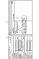
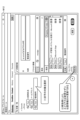
- 5 to 20 are diagrams showing examples of menu screens displayed on the automatic operation target device.
- the automatic operation target device may be a terminal device to which the processing device 10 is connected.
- the present embodiment is realized as software in which an execution unit 154, a target registration unit 151, and a target monitoring unit 153 are implemented as an application that resides in the task tray, for example.
- an execution unit 154, a target registration unit 151, and a target monitoring unit 153 are implemented as an application that resides in the task tray, for example.
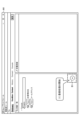
- a menu M1 is displayed as a developer tool.
- a list of targets is displayed in the left area R1 on the Dictionary screen of the menu M1 ((1) in FIG. 6).
- position information is displayed in the right area R2 ((2) in FIG. 6), and aliases are displayed in the right area R3 ((3) in FIG. 6).
- the Dictionary screen displays a registration process start button B1 and a registration update button B2.
- a dictionary acquisition start menu M2-2 is displayed.
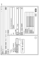
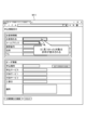
- the user performs an operation such as clicking an automatic operation target C1 to be registered with a mouse, the clicked event is observed and the target is highlighted in a red frame W1 ((2) in FIG. 8).
- the object C1 is a telephone number
- observed events are listed in the dictionary acquisition start menu M2-2 (in this example, an event of focusing on a telephone number is listed).
- the add button B3 ((3) in FIG. 8).
- the object registration unit 151 specifies the selected object C1 and generates position information of the specified object C1. As a result, the position information of the target C1 is automatically generated ((4) in FIG. 9) and displayed in the area R2 on the left side of the menu M1. Then, the object registration unit 151 sets the alias of this object C1 as "telephone number" ((5) in FIG. 9, area R3). Note that the telephone number of the target C1 selected in the application information reception menu M2-1 of FIG. 8 is displayed in the telephone number column C2 of "Customer Information".
- the target registration unit 151 stores the phone number of the target C1, the alias "telephone number”, and the location information of the target C1. are added to the target list as one set ((7) in FIG. 10, area R1-2).
- FIG. 11 illustrates a menu M2 for setting properties for automatic operation.
- the position information of target C1 is specified by object information (properties) ((1) in FIG. 11).
- the position information of the target C1 is specified by an index in each hierarchy of the automatic operation target ((2) in FIG. 12).
- the user can also specify what kind of object to pass through at the relay point of the hierarchy in the route setting area R2-2 of the position information of the menu M1 (FIG. 13 (1)).
- Specifying a relay point can speed up object identification. In this way, by combining object properties and indexes as target location information, and by making it possible to flexibly set relay points, it is possible to flexibly set the display position of the target object even when the display position of the target object cannot be determined in the first place. You can set and specify location information.
- conditions can be registered on the Condition screen of menu M1.
- a list of conditions is displayed in the left region R31 ((1) in FIG. 14).
- a condition name column in which a condition name can be defined is displayed in the right area R32 ((2) in FIG. 14).
- a setting column in which an alias can be set is displayed in the right area R33 ((3) in FIG. 14).
- a setting field in which conditions can be set is displayed in the right area R34 ((4) in FIG. 14).
- "when a telephone number including 070 is set” is set as the condition.
- a registration update button is displayed on the Condition screen.
- the object registration unit 151 sets the conditions for the object C1 registered on the Dictionary screen of the menu M1 according to the settings on the Condition screen.
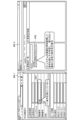
- the target monitoring unit 153 constantly monitors the system screen and determines whether the conditions are met (FIG. 15(2)). In this case, the condition "when a telephone number including 070 is set” set in FIG. 14 is not satisfied ((1) in FIG. 15). If the condition is not satisfied, the target monitoring unit 153 displays the condition name in red, for example, on the Condition screen of menu M4-2 (area R42 in FIG. 15).
- the target monitoring unit 153 constantly monitors the system screen and determines whether the conditions are met (FIG. 16(4)). In this case, the condition "when a telephone number including 070 is set” set in FIG. 14 is satisfied ((3) in FIG. 16). Therefore, when the condition is satisfied, the target monitoring unit 153 displays the condition name in green, for example, on the Condition screen of the menu M4-4 (area R44 in FIG. 16).
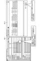
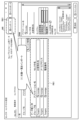
- FIG. 17 illustrates the Lua script language.
- the script is written using the alias set by the target registration unit 151 ((2) in FIG. 17, areas R51 and R52).
- the execution unit 154 replaces the alias with object information to be automatically operated. Then, the script is sequentially processed by the execution unit 154, and automatic operation of the system screen is executed ((3) in FIG. 17). As a result, "dummy@ntt.com" is automatically entered in the email address field C51 of the application information reception menu M5-1.
- the user can output (export) the target list in the area R11 by pulling down File in the menu M1 and selecting the Export column D1.
- the control description unit 152 describes automatic operation control using low-code and/or no-code for the targets in the target list ((1) in FIG. 20).
- FIG. 20 illustrates block-type visual programming.
- the control description section 152 sets the description content using the alias of the imported target list ((2) in FIG. 20 and areas R71 to R73). Then, the control description section 152 converts it into a script that can be interpreted by the execution section 154 ((3) in FIG. 21 and box M75 in FIG. 21).
- FIG. 22 is a flowchart showing the procedure for updating the target list when the system screen changes.
- the target registration unit 151 performs a target check on the system screen to be checked (step S41), and if there is any position information not found in the target list 141, , the target is highlighted (step S42).
- the target registration unit 151 reacquires the position information of the highlighted target on the system screen (step S44), and selects this target from the target list 141. Update the location information to the reacquired location information.
- the target registration unit 151 determines whether the necessary corrections have been completed for the system screen to be checked (step S45). If the necessary corrections have not been completed for the system screen to be checked (step S45: No), the target registration unit 151 returns to step S43. If the necessary corrections have been completed for the system screen to be checked (step S45: Yes), the process for updating the target list for this system screen is ended.
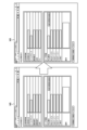
- FIGS. 23 to 28 are diagrams showing examples of menu screens displayed on the automatic operation target device. An example in which the system screen is changed from menu M8 to menu M9 in FIG. 23 will be described. In menu M9, the location information of the telephone number is different from that in menu M8.
- a frame for example, a red frame
- a change in position information is found ((2) in FIG. 25).
- the target that cannot be found (phone number in this case) will be displayed in red, for example. is displayed ((3) in FIG. 26).
- the target registration unit 151 updates only the location information for the target in red (phone number in this case) without changing the alias by re-acquiring the location information in the phone number field on the system screen after the change. ((2) in Figure 27).
- the target registration unit 151 updates only the position information without modifying the alias for those having the same target (phone number in this case) in the target list.
- the object registration unit 151 re-acquires the position information of this object,
- the location information of this target in the target list is updated to the reacquired location information.
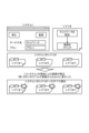
- FIG. 29 is a diagram explaining conventional RPA.
- existing RPA automatic operation targets and control information are written together in the form of scenarios and rules.
- the system screen that is the target of the operation is modified due to an update to the system 1 (for example, when the button label changes from "Register” to "Submit") ( (1) in Figure 29)
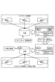
- FIG. 30 is a diagram illustrating the processing device 10 according to the embodiment. As shown in FIG. 29, the processing device 10 separates control and automatic operation targets and manages automatic operations. The processing device 10 aggregates information that is easily affected by the environment, such as system screens, into target information (aliases, monitoring conditions) and generates the information for each system ((1) in FIG. 30).
- target information aliases, monitoring conditions
- the processing device 10 even if the system screen that is the target of a dynamic operation is modified due to a system update ((2) in FIG. 30), the scope of modification is limited to only the target information ( (3) in Figure 30). In the processing device 10, since there is no need to modify the control of the system 1, the modified target information may be used in the description of the control.
- the position information of the automatic operation target registered by the target registration unit 151 is expressed hierarchically using object information or an index, so that the position information of the automatic operation target can be appropriately registered. Furthermore, in the processing device 10, since a unique alias is defined for each piece of positional information, it is possible to appropriately manage the positional information of the automatic operation target.
- control description unit 152 uses aliases to set conditions including existence conditions, value conditions, and/or timing conditions, and defines a unique condition name for each condition. Conditions can be managed appropriately.
- control description unit 152 describes control using one of the following execution methods: immediate execution and execution when an execution condition set by combining condition names is met. Therefore, compared to the conventional method of creating all scenarios and rules as one, the processing device 10 does not have to consider all the scenarios and rules, and the processing device 10 waits until the system screen transitions to the next screen to automatically It is also possible to easily describe procedures such as ⁇ waiting until a scenario or rule can be executed by monitoring the screen'' such as performing an operation.
- Each component of the processing device 10 is functionally conceptual, and does not necessarily need to be physically configured as illustrated.
- the specific form of distributing and integrating the functions of the processing device 10 is not limited to what is shown in the diagram, and all or part of it can be functionally or physically distributed in arbitrary units depending on various loads and usage conditions. It can be configured to be distributed or integrated.
- each process performed in the processing device 10 may be realized by a CPU, a GPU (Graphics Processing Unit), or a program that is analyzed and executed by the CPU or GPU.
- each process performed in the processing device 10 may be realized as hardware using wired logic.
- FIG. 31 is a diagram illustrating an example of a computer that implements the processing device 10 by executing a program.
- Computer 1000 includes, for example, a memory 1010 and a CPU 1020.
- the computer 1000 also includes a hard disk drive interface 1030, a disk drive interface 1040, a serial port interface 1050, a video adapter 1060, and a network interface 1070. These parts are connected by a bus 1080.
- the memory 1010 includes a ROM 1011 and a RAM 1012.
- the ROM 1011 stores, for example, a boot program such as BIOS (Basic Input Output System).
- Hard disk drive interface 1030 is connected to hard disk drive 1090.
- Disk drive interface 1040 is connected to disk drive 1100.
- Serial port interface 1050 is connected to, for example, mouse 1110 and keyboard 1120.
- Video adapter 1060 is connected to display 1130, for example.
- the hard disk drive 1090 stores, for example, an OS (Operating System) 1091, an application program 1092, a program module 1093, and program data 1094. That is, a program that defines each process of the processing device 10 is implemented as a program module 1093 in which code executable by the computer 1000 is written.
- Program module 1093 is stored in hard disk drive 1090, for example.
- a program module 1093 for executing processing similar to the functional configuration in the processing device 10 is stored in the hard disk drive 1090.
- the hard disk drive 1090 may be replaced by an SSD (Solid State Drive).
- the setting data used in the processing of the embodiment described above is stored as program data 1094 in, for example, the memory 1010 or the hard disk drive 1090. Then, the CPU 1020 reads out the program module 1093 and program data 1094 stored in the memory 1010 and the hard disk drive 1090 to the RAM 1012 as necessary and executes them.
- program module 1093 and the program data 1094 are not limited to being stored in the hard disk drive 1090, but may be stored in a removable storage medium, for example, and read by the CPU 1020 via the disk drive 1100 or the like.
- the program module 1093 and the program data 1094 may be stored in another computer connected via a network (LAN (Local Area Network), WAN (Wide Area Network), etc.). The program module 1093 and program data 1094 may then be read by the CPU 1020 from another computer via the network interface 1070.
- LAN Local Area Network
- WAN Wide Area Network
Landscapes
- Engineering & Computer Science (AREA)
- Software Systems (AREA)
- General Engineering & Computer Science (AREA)
- Theoretical Computer Science (AREA)
- Physics & Mathematics (AREA)
- General Physics & Mathematics (AREA)
- User Interface Of Digital Computer (AREA)
Abstract
Description
本実施の形態では、システム画面の自動操作を行う処理装置及び処理方法について説明する。
実施の形態に係る処理装置について説明する。図1は、図1に示すように、処理装置10は、入力部11、出力部12、通信部13、記憶部14及び制御部15を有する。
図2は、実施の形態に係るシステム画面の自動操作処理の処理手順を示すフローチャートである。
次に、対象登録処理(ステップS1)について説明する。図3は、図2に示す対象登録処理の処理手順を示すフローチャートである。
次に、制御記述処理(ステップS2)について説明する。図4は、図2に示す制御記述処理の処理手順を示すフローチャートである。
次に、本実施の形態における自動操作制御処理の実装例について説明する。図5~図20は、自動操作対象装置に表示されるメニュー画面の一例を示す図である。自動操作対象装置は、処理装置10のほか、処理装置10が接続する端末装置であってもよい。
まず、対象の登録処理について説明する。図7に示すように、まず、ユーザは、メニューM1のDictionary画面の開始ボタンB1を選択することで、登録処理の開始を指示する(図7の(1))。
続いて、対象監視部153の動作について説明する。例えば、図15に示すように、申込情報受付メニューM4-1の電話番号欄(領域R41)に、「090」が入力された場合を例に説明する。
次に、実行部154の動作について説明する。例えば、図17のconsole画面M5-2に示すように、実行部154は、対応するスクリプトを解釈して、処理する(図17の(1))。図17では、Luaスクリプト言語を例示する。スクリプトは、対象登録部151で設定したエイリアスを用いて記述される(図17の(2)、領域R51,R52)。
次に、制御記述部152を実装したソフトウェアの実装例について説明する。図19のメニューM6において、インポートボタンB61を選択することで、対象一覧をインポートする(図19の(1)及び領域R61)。
次に、システム画面が変わったときの対象一覧141の更新の手順について説明する。図22は、システム画面が変わったときの対象一覧の更新処理の手順を示すフローチャートである。
図29は、従来のRPAについて説明する図である。既存のRPAではシナリオやルールといった形で自動操作対象と制御の情報が一体として記述されている。このため、従来のRPAはでは、システム1の更改により、動操作の対象となるシステム画面の修正が行われた場合(例えば、ボタンのラベルが「登録」から「Submit」に変わった場合)(図29の(1))、該当のシステム画面に関連する全てのシナリオやルールの修正が必要であった(図29の(2))。
処理装置10の各構成要素は機能概念的なものであり、必ずしも物理的に図示のように構成されていることを要しない。すなわち、処理装置10の機能の分散及び統合の具体的形態は図示のものに限られず、その全部または一部を、各種の負荷や使用状況などに応じて、任意の単位で機能的または物理的に分散または統合して構成することができる。
図31は、プログラムが実行されることにより、処理装置10が実現されるコンピュータの一例を示す図である。コンピュータ1000は、例えば、メモリ1010、CPU1020を有する。また、コンピュータ1000は、ハードディスクドライブインタフェース1030、ディスクドライブインタフェース1040、シリアルポートインタフェース1050、ビデオアダプタ1060、ネットワークインタフェース1070を有する。これらの各部は、バス1080によって接続される。
11 入力部
12 出力部
13 通信部
14 記憶部
15 制御部
141 対象一覧
142 条件一覧
151 対象登録部
152 制御記述部
153 対象監視部
154 実行部
Claims (7)
- システム画面に表示された自動操作対象を指定し、指定した前記自動操作対象の位置情報とエイリアスとを対象情報として登録及び管理する登録部と、
前記登録部によって登録された前記対象情報を用いて、自動操作の制御をローコード及び/またはノーコードにより記述し、実行条件がある場合に実行条件を記述し、所定のスクリプトへと変換する記述部と、
デスクトップ上のアプリケーションの情報を監視し、前記記述部によって設定された実行条件を満たすか否かを判定し、前記実行条件を満たすと判定した場合、対応するスクリプトを出力する監視部と、
前記記述部によって変換されたスクリプトを解釈し、前記エイリアスを自動操作対象のオブジェクト情報に置換し、前記スクリプトを逐次的に処理し、前記システム画面の自動操作を行う実行部と、
を有することを特徴とする処理装置。 - 前記登録部が登録する前記自動操作対象の位置情報は、オブジェクト情報またはインデックスにより階層的に表現され、
前記登録部は、各位置情報に、一意なエイリアスを定義することを特徴とする請求項1に記載の処理装置。 - 前記登録部は、エイリアスを用いて、存在条件、値条件及び/またはタイミング条件を含む条件を設定し、各条件に一意な条件名を定義することを特徴とする請求項1に記載の処理装置。
- 前記記述部は、即時実行と、条件名を組み合わせて設定した実行条件を満たす場合に実行、とのいずれかの実行方法を用いて、制御を記述することを特徴とする請求項1に記載の処理装置。
- 前記登録部は、システム画面が変更された場合、変更後のシステム画面について、前記対象情報の中で位置情報が見つからない第1の対象がある場合、前記第1の対象の位置情報を再取得し、前記対象情報のうち、前記第1の対象の位置情報を、再取得した位置情報に更新することを特徴とする請求項1に記載の処理装置。
- 処理装置が実行する処理方法であって、
システム画面に表示された自動操作対象を指定し、指定した前記自動操作対象の位置情報とエイリアスとを対象情報として登録及び管理する登録工程と、
前記登録工程において登録された前記対象情報を用いて、自動操作の制御をローコード及び/またはノーコードにより記述し、実行条件がある場合に実行条件を記述し、所定のスクリプトへと変換する記述工程と、
デスクトップ上のアプリケーションの情報を監視し、前記記述工程において設定された実行条件を満たすか否かを判定し、前記実行条件を満たすと判定した場合、対応するスクリプトを出力する監視工程と、
前記記述工程において変換されたスクリプトを解釈し、前記エイリアスを自動操作対象のオブジェクト情報に置換し、前記スクリプトを逐次的に処理し、前記システム画面の自動操作を行う実行工程と、
を含んだことを特徴とする処理方法。 - システム画面に表示された自動操作対象を指定し、指定した前記自動操作対象の位置情報とエイリアスとを対象情報として登録及び管理する登録ステップと、
前記登録ステップにおいて登録された前記対象情報を用いて、自動操作の制御をローコード及び/またはノーコードにより記述し、実行条件がある場合に実行条件を記述し、所定のスクリプトへと変換する記述ステップと、
デスクトップ上のアプリケーションの情報を監視し、前記記述ステップにおいて設定された実行条件を満たすか否かを判定し、前記実行条件を満たすと判定した場合、対応するスクリプトを出力する監視ステップと、
前記記述ステップにおいて変換されたスクリプトを解釈し、前記エイリアスを自動操作対象のオブジェクト情報に置換し、前記スクリプトを逐次的に処理し、前記システム画面の自動操作を行う実行ステップと、
をコンピュータに実行させるための処理プログラム。
Priority Applications (2)
| Application Number | Priority Date | Filing Date | Title |
|---|---|---|---|
| PCT/JP2022/020103 WO2023218615A1 (ja) | 2022-05-12 | 2022-05-12 | 処理装置、処理方法及び処理プログラム |
| JP2024520192A JP7803409B2 (ja) | 2022-05-12 | 2022-05-12 | 処理装置、処理方法及び処理プログラム |
Applications Claiming Priority (1)
| Application Number | Priority Date | Filing Date | Title |
|---|---|---|---|
| PCT/JP2022/020103 WO2023218615A1 (ja) | 2022-05-12 | 2022-05-12 | 処理装置、処理方法及び処理プログラム |
Publications (1)
| Publication Number | Publication Date |
|---|---|
| WO2023218615A1 true WO2023218615A1 (ja) | 2023-11-16 |
Family
ID=88730155
Family Applications (1)
| Application Number | Title | Priority Date | Filing Date |
|---|---|---|---|
| PCT/JP2022/020103 Ceased WO2023218615A1 (ja) | 2022-05-12 | 2022-05-12 | 処理装置、処理方法及び処理プログラム |
Country Status (2)
| Country | Link |
|---|---|
| JP (1) | JP7803409B2 (ja) |
| WO (1) | WO2023218615A1 (ja) |
Citations (1)
| Publication number | Priority date | Publication date | Assignee | Title |
|---|---|---|---|---|
| JP2013152697A (ja) * | 2011-12-28 | 2013-08-08 | Alps Electric Co Ltd | 入力装置及び電子機器 |
-
2022
- 2022-05-12 JP JP2024520192A patent/JP7803409B2/ja active Active
- 2022-05-12 WO PCT/JP2022/020103 patent/WO2023218615A1/ja not_active Ceased
Patent Citations (1)
| Publication number | Priority date | Publication date | Assignee | Title |
|---|---|---|---|---|
| JP2013152697A (ja) * | 2011-12-28 | 2013-08-08 | Alps Electric Co Ltd | 入力装置及び電子機器 |
Non-Patent Citations (1)
| Title |
|---|
| HIDETAKA KOYA, MAKOTO KOMIYAMA, HAJIME NAKAJIMA, AKIRA KATAOKA, TAKESHI MASUDA: "Proposal and evaluation of the method for end-user configuration of the user interface augmentation", 2017 INTERNATIONAL SYMPOSIUM ON NONLINEAR THEORY AND ITS APPLICATIONS, NOLTA2017, CANCUN, MEXICO, DECEMBER 4-7, 2017, IEICE, JP, vol. 119, no. 52 (ICM2019-4), 16 May 2019 (2019-05-16), JP , pages 59 - 64, XP009537446 * |
Also Published As
| Publication number | Publication date |
|---|---|
| JP7803409B2 (ja) | 2026-01-21 |
| JPWO2023218615A1 (ja) | 2023-11-16 |
Similar Documents
| Publication | Publication Date | Title |
|---|---|---|
| US12206548B1 (en) | Dynamic application configuration techniques | |
| US9262237B2 (en) | Automating software availability management based on API versioning | |
| US9652220B2 (en) | Zero down-time deployment of new application versions | |
| US8332431B2 (en) | Configuration information management apparatus, configuration information management program, and configuration information management method | |
| CN110221899B (zh) | 一种用户界面的调节方法、装置及系统 | |
| CN114661375B (zh) | 应用集成方法及装置 | |
| US11921496B2 (en) | Information processing apparatus, information processing method and computer readable medium | |
| WO2019039255A1 (ja) | 端末装置、ui拡張方法及びui拡張プログラム | |
| CN111459376A (zh) | 产品引导方法、装置及设备 | |
| EP3819758A2 (en) | Instruction executing method and apparatus, electronic device, and computer-readable storage medium | |
| JP2020004280A (ja) | 表示制御装置、表示制御方法、および表示制御プログラム | |
| US9710495B2 (en) | Business rules manager | |
| US10339102B2 (en) | Automating script creation for a log file | |
| JP7803409B2 (ja) | 処理装置、処理方法及び処理プログラム | |
| US20080098379A1 (en) | System and method of configuring computer settings | |
| CN110502296B (zh) | 一种显示固件升级命令的方法、设备以及存储介质 | |
| US20050066016A1 (en) | Interface for configuring internet communications on a z series computer | |
| US11750458B1 (en) | Structured network change controls | |
| CN111124386A (zh) | 基于Unity的动画事件处理方法、装置、设备和存储介质 | |
| EP3418913A1 (en) | System and method for merging a source data from a source application into a target data of a target application | |
| CN102236583B (zh) | 现场装置管理设备 | |
| CN113626051A (zh) | 字节码的更新方法、装置及电子设备 | |
| JP7838644B2 (ja) | 表示制御システム、表示制御方法、および、表示制御プログラム | |
| JP2012108740A (ja) | 入力支援方法及びプログラム | |
| US20240378138A1 (en) | Software testing with multiple instances of policy management system |
Legal Events
| Date | Code | Title | Description |
|---|---|---|---|
| 121 | Ep: the epo has been informed by wipo that ep was designated in this application |
Ref document number: 22941695 Country of ref document: EP Kind code of ref document: A1 |
|
| ENP | Entry into the national phase |
Ref document number: 2024520192 Country of ref document: JP Kind code of ref document: A |
|
| WWE | Wipo information: entry into national phase |
Ref document number: 18863807 Country of ref document: US |
|
| NENP | Non-entry into the national phase |
Ref country code: DE |
|
| 122 | Ep: pct application non-entry in european phase |
Ref document number: 22941695 Country of ref document: EP Kind code of ref document: A1 |