WO2023218587A1 - 圧縮機及び冷凍サイクル装置 - Google Patents
圧縮機及び冷凍サイクル装置 Download PDFInfo
- Publication number
- WO2023218587A1 WO2023218587A1 PCT/JP2022/020021 JP2022020021W WO2023218587A1 WO 2023218587 A1 WO2023218587 A1 WO 2023218587A1 JP 2022020021 W JP2022020021 W JP 2022020021W WO 2023218587 A1 WO2023218587 A1 WO 2023218587A1
- Authority
- WO
- WIPO (PCT)
- Prior art keywords
- container
- compressor
- stator
- refrigerant
- muffler
- Prior art date
- Legal status (The legal status is an assumption and is not a legal conclusion. Google has not performed a legal analysis and makes no representation as to the accuracy of the status listed.)
- Ceased
Links
Images





Classifications
-
- F—MECHANICAL ENGINEERING; LIGHTING; HEATING; WEAPONS; BLASTING
- F04—POSITIVE - DISPLACEMENT MACHINES FOR LIQUIDS; PUMPS FOR LIQUIDS OR ELASTIC FLUIDS
- F04B—POSITIVE-DISPLACEMENT MACHINES FOR LIQUIDS; PUMPS
- F04B39/00—Component parts, details, or accessories, of pumps or pumping systems specially adapted for elastic fluids, not otherwise provided for in, or of interest apart from, groups F04B25/00 - F04B37/00
-
- F—MECHANICAL ENGINEERING; LIGHTING; HEATING; WEAPONS; BLASTING
- F04—POSITIVE - DISPLACEMENT MACHINES FOR LIQUIDS; PUMPS FOR LIQUIDS OR ELASTIC FLUIDS
- F04C—ROTARY-PISTON, OR OSCILLATING-PISTON, POSITIVE-DISPLACEMENT MACHINES FOR LIQUIDS; ROTARY-PISTON, OR OSCILLATING-PISTON, POSITIVE-DISPLACEMENT PUMPS
- F04C29/00—Component parts, details or accessories of pumps or pumping installations, not provided for in groups F04C18/00 - F04C28/00
- F04C29/12—Arrangements for admission or discharge of the working fluid, e.g. constructional features of the inlet or outlet
Definitions
- the present disclosure relates to a compressor and a refrigeration cycle device that include a fixture that connects a closed container and a suction muffler.
- compressors that include a suction muffler that is connected to a suction pipe and suppresses noise generated from refrigerant flowing through the suction pipe.
- the suction muffler is fixed to the closed container using a fixing fitting.
- Patent Document 1 discloses a compressor that includes a compression mechanism section that compresses a gaseous refrigerant in a closed container, and an electric mechanism section that drives the compression mechanism section.
- a closed container and a suction muffler are fixed via a suction muffler fixing fitting.
- the airtight container and the suction muffler are fixed by projection welding and joining the airtight container and the suction muffler, and by arc welding and joining the fixing metal fitting and the suction muffler. .
- the present disclosure solves the above-mentioned problems, and aims to provide a compressor and a refrigeration cycle device that suppress the generation of abnormal noise.
- a compressor includes an electric mechanism having an airtight container having an outer shell extending in a first direction, a stator provided inside the airtight container, and a rotor rotated by the stator; A shaft that is attached to the shaft and transmits the rotational force of the electric mechanism, a compression mechanism that rotates as the shaft rotates and compresses the refrigerant, a suction pipe that flows the refrigerant into the compression mechanism, and a suction pipe that is connected to the suction pipe and It includes a suction muffler that suppresses noise generated from refrigerant flowing through the pipes, and a fixing fitting that connects the suction muffler and the sealed container, the fixing fitting being joined to the sealed container and displacing with respect to the stator in the first direction.
- a base part having a container-side joint part that is provided at a position where the container side protrudes toward the closed container side; an extension part that extends from both ends of the base part; and an abutment that is provided at the tip of the extension part and that comes into contact with the suction muffler. It has a section and a.
- the container-side joint portion in the base portion of the fixture is provided at a position shifted from the stator in the first direction. Therefore, even if vibrations generated by the stator propagate to the sealed container, the vibrations propagated to the sealed container are unlikely to propagate to the suction muffler via the fixing fittings. Thereby, it is possible to suppress vibrations from propagating to the refrigerant piping. Therefore, generation of abnormal noise can be suppressed.
- FIG. 1 is a circuit diagram showing a refrigeration cycle device according to Embodiment 1.
- FIG. 1 is a sectional view showing a compressor according to the first embodiment.
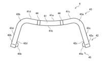
- FIG. 3 is a top view showing the fixture according to the first embodiment.
- FIG. 3 is a side view showing the fixture according to the first embodiment.
- 1 is a side view showing a compressor according to Embodiment 1.
- FIG. 1 is a side view showing a compressor according to Embodiment 1.
- FIG. 7 is a side view showing a fixture according to the second embodiment.
- FIG. 2 is a side view showing a compressor according to a second embodiment.
- FIG. 1 is a circuit diagram showing a refrigeration cycle device 12 according to the first embodiment.
- the refrigeration cycle device 12 is, for example, a water heater, and includes a heat source device 17 and utilization equipment 18, as shown in FIG.
- the heat source device 17 is provided with, for example, a compressor 1, a first heat exchanger 13, an expansion section 15, and a second heat exchanger 16.
- the compressor 1, the first heat exchanger 13, the expansion section 15, and the second heat exchanger 16 are connected by a refrigerant pipe 12b to form a refrigerant circuit 12a.
- the compressor 1 takes in refrigerant at low temperature and low pressure, compresses the sucked refrigerant, converts it into refrigerant at high temperature and high pressure, and discharges the refrigerant.
- the compressor 1 is, for example, a single rotary type compressor 1 whose capacity can be controlled.
- the first heat exchanger 13 exchanges heat between, for example, water flowing in the water circuit 14a and a refrigerant, and functions as a gas cooler.
- the expansion section 15 is a pressure reducing valve or an expansion valve that reduces the pressure of the refrigerant and expands it.
- the expansion section 15 is, for example, an electronic expansion valve whose opening degree is adjusted.
- the second heat exchanger 16 exchanges heat between air and refrigerant, for example, and functions as an evaporator.
- a water circuit 14a is configured by connecting the second heat exchanger 16 and the utilization equipment 18 through a water pipe 14b.
- the second heat exchanger 16 is for exchanging heat between, for example, the refrigerant flowing in the refrigerant circuit 12a and water.
- the utilization device 18 supplies hot water using the heat generated by the heat source device 17.
- hot water supply operation of refrigeration cycle device 12 Next, hot water supply operation will be explained.
- the refrigerant sucked into the compressor 1 is compressed by the compressor 1 and discharged in a high temperature and high pressure gas state.
- the high temperature and high pressure gaseous refrigerant discharged from the compressor 1 flows into the second heat exchanger 16 that acts as a gas cooler, and in the second heat exchanger 16 heat exchanges with the water flowing into the water circuit 14a. It condenses and liquefies. At this time, the water flowing into the water circuit 14a is warmed.
- the condensed liquid refrigerant flows into the expansion section 15, where it is expanded and depressurized to become a low-temperature, low-pressure gas-liquid two-phase refrigerant.
- the gas-liquid two-phase refrigerant flows into the first heat exchanger 13 that functions as an evaporator, where it exchanges heat with air, evaporates, and gasifies.
- the evaporated low-temperature, low-pressure gaseous refrigerant is sucked into the compressor 1 .
- the refrigeration cycle device 12 is not limited to a water heater, but may be a floor heating device, an air conditioner, or the like.
- the refrigeration cycle device 12 is an air conditioning device, if it has a flow path switching device, it can perform both cooling operation and heating operation.
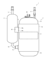
- FIG. 2 is a sectional view showing the compressor 1 according to the first embodiment.
- the compressor 1 is a rolling piston type single rotary compressor, and is a fluid machine that discharges a low-pressure gaseous refrigerant sucked into the compressor as a high-pressure gaseous refrigerant.
- the housing of the compressor 1 is constituted by an iron closed container 3 formed in a cylindrical shape.
- the closed container 3 has an outer shell extending in the first direction Z.
- the vertical direction will be referred to as a first direction Z.
- the airtight container 3 is composed of a hollow cylindrical body portion 3a, a bottom portion 3b having a U-shaped vertical section, and a lid portion 3c having an inverted U-shaped vertical cross section.
- the outer surface of the body portion 3a is fixed to the inner surface of the opening of the body portion 3a.
- the fixed portion between the body portion 3a and the bottom portion 3b and the fixed portion between the body portion 3a and the lid portion 3c are joined by, for example, arc welding or resistance welding.
- Refrigerating machine oil 90 is stored in the bottom 3b of the airtight container 3.
- a suction muffler 2 is arranged outside the body portion 3a of the closed container 3.
- the suction muffler 2 is fixed to the body portion 3a of the closed container 3 via a fixture 4 disposed on the outer surface of the closed container 3.
- the suction muffler 2 has an upper container 2a and a lower container 2b, and has a cylindrical shape.
- the upper container 2a and the lower container 2b are fixed by, for example, welding.
- a suction pipe 5 is fixed to the top of the upper container 2a constituting the suction muffler 2, passing through the upper container 2a.
- the suction pipe 5 is a refrigerant pipe 12b that allows a low-pressure gas refrigerant or a highly dry two-phase refrigerant to flow into the suction muffler 2. Further, one end of an inflow pipe 5a passes through the bottom part 3b of the lower container 2b constituting the suction muffler 2 and is fixed by welding or the like. It is fixed through the side part.
- the suction muffler 2 also has an accumulator function, and has a refrigerant storage function that stores excess refrigerant and separates the refrigerant into gas and liquid by retaining the liquid refrigerant that is temporarily generated when the operating condition changes. It has a gas-liquid separation function. Further, the suction muffler 2 also has a function as a muffler that reduces or eliminates noise generated by the refrigerant flowing from the suction pipe 5. The gas-liquid separation function of the suction muffler 2 can prevent a large amount of liquid refrigerant from flowing into the closed container 3 and from being compressed by the compressor 1. In addition, the detailed structure of the fixture 4 which connects the airtight container 3 and the suction muffler 2 will be described later.
- the inflow pipe 5a is a refrigerant pipe 12b that draws low-pressure gaseous refrigerant from the suction muffler 2 into the sealed container 3.
- a fixing member 5c is disposed in the suction hole 5b formed in the body portion 3a of the hermetic container 3, and the inflow pipe 5a is connected to the body of the hermetic container 3 via the fixing member 5c disposed in the suction hole 5b. It is fixed to part 3a.
- the connecting pipe 6a is inserted into the suction hole 5b, and communicates with the inside of the closed container 3.
- the inflow pipe 5a is inserted into the other end of the fixing member 5c.
- the fixing member 5c is joined to the suction hole 5b, the outer surface of the connecting pipe 6a, and the closed container 3, and seals the gap between the inflow pipe 5a and the suction hole 5b. In the compressor 1, the airtightness of the inside of the closed container 3 is ensured by the fixing member 5c.
- a discharge pipe 6 penetrates and is fixed to the upper surface of the lid 3c of the closed container 3.
- the discharge pipe 6 is a refrigerant pipe 12b that discharges high-pressure gaseous refrigerant to the outside of the closed container 3.
- the fixed portions of the discharge pipe 6 and the lid portion 3c are joined by, for example, brazing or resistance welding.
- a glass terminal 60 is arranged on the upper surface of the lid portion 3c of the closed container 3. Glass terminal 60 provides an interface to be connected to an external power source (not shown).
- the external power source is a power supply device that supplies power to the compressor 1, and uses a general commercial AC power source with an AC frequency of 50 Hz or 60 Hz, or an inverter power source that can change the AC frequency.
- the electric mechanism 7, the shaft 70, and the compression mechanism 10 are housed inside the closed container 3.
- the electric mechanism 7 is arranged above the position of the fixing member 5c in the closed container 3.
- the shaft 70 is disposed between the electric mechanism 7 and the compression mechanism 10 in the center of the closed container 3, and is provided so as to extend in the vertical direction between the electric mechanism 7 and the compression mechanism 10.
- the compression mechanism 10 is arranged so that the inside of the compression mechanism 10 communicates with the inflow pipe 5a. That is, inside the closed container 3, the electric mechanism 7 is arranged above the compression mechanism 10. Further, the hollow space inside the closed container 3 is filled with a high-pressure gaseous refrigerant compressed by the compression mechanism 10. That is, the compressor 1 is a high pressure shell type.
- the electric mechanism 7 is configured as a motor that generates rotational driving force on the shaft 70 using electric power supplied from an external power source, and transmits the rotational driving force to the compression mechanism 10 via the shaft 70.
- the electric mechanism 7 includes a stator 8 having a hollow cylindrical appearance when viewed from above, and a cylindrical rotor 9 rotatably disposed inside the inner surface of the stator 8.
- the stator 8 is fixed to the inner surface of the body portion 3a of the closed container 3 by shrink fitting or the like, and is connected to the glass terminal 60 via a conductive wire 61.
- the electric mechanism 7 operates the rotor 9 inside the inner surface of the stator 8 by supplying electric power from an external power source to the wound coils constituting the stator 8 via the conducting wire 61. It can be rotated.
- a DC brushless motor or the like is used as the electric mechanism 7, for example.
- a shaft 70 is fixed to the center of the rotor 9 so as to pass through the rotor 9.
- the shaft 70 is a rotating shaft that fixes the rotor 9 at a fixing surface 70 a that is a part of the outer surface of the shaft 70 and transmits the rotational force of the rotor 9 to the compression mechanism 10 .
- the shaft 70 is provided to extend in the vertical direction from the fixed surface 70a, that is, in the direction of the lid 3c of the closed container 3 and in the direction of the bottom 3b of the closed container 3.
- the shaft 70 has an eccentric portion 71 located below the fixed surface 70a and located at a position corresponding to the cylinder 73 inside the compression mechanism 10.
- a substantially cylindrical piston 72 is disposed on the outer periphery of the eccentric portion 71 and is rotatably attached along the outer surface of the eccentric portion 71 .
- the piston 72 rotates within the cylinder 73 along its inner peripheral surface.
- the compressor 1 may include a centrifugal pump (not shown) disposed at the lower end of the shaft 70.
- the centrifugal pump can suck up the refrigerating machine oil 90 stored in the bottom 3b of the closed container 3.
- the refrigerating machine oil 90 for example, mineral oil-based, alkylbenzene-based, polyalkylene glycol-based, polyvinyl ether-based, polyol ester-based lubricating oil, etc. are used.
- the compression mechanism 10 compresses the low-pressure gaseous refrigerant drawn into the low-pressure space of the closed container 3 from the inflow pipe 5a into a high-pressure gaseous refrigerant using the rotational driving force supplied from the electric mechanism 7. High pressure gaseous refrigerant is discharged above the compression mechanism 10.
- the compression mechanism 10 includes a hollow cylindrical cylinder 73.
- the outer surface of the cylinder 73 is fixed to the inner surface of the body portion 3a of the closed container 3 by arc welding such as arc spot welding or shrink fitting.
- the eccentric portion 71 of the shaft 70 and the piston 72 are housed in a hollow space surrounded by the inner surface of the cylinder 73 .
- the cylinder 73 is configured such that the eccentric portion 71 of the shaft 70 and the piston 72 can rotate eccentrically by rotation of the shaft 70 in the hollow portion of the cylinder 73 .
- a compression chamber is formed in the cylinder 73 by one end of a vane 74 that reciprocates in the radial direction within a groove formed in the cylinder 73 and comes into contact with the muffler outer circumferential wall 2c of the piston 72.
- the openings at both axial ends of the cylinder 73 are closed by an upper bearing 75 and a lower bearing 76. That is, an upper bearing 75 is arranged above the cylinder 73, and a lower bearing 76 is arranged below the cylinder 73.
- the shaft 70 passes through the upper bearing 75, the cylinder 73, and the lower bearing 76.
- the upper bearing 75 and the lower bearing 76 are sliding bearings that slidably support the shaft 70, and support the shaft 70 rotatably.
- the upper bearing 75, the cylinder 73, and the lower bearing 76 are stacked in this order, and the upper and lower openings of the hollow part of the cylinder 73 are closed by the upper bearing 75 and the lower bearing 76, thereby ensuring airtightness within the hollow part.
- the upper bearing 75 and the lower bearing 76 are fixed to the upper and lower sides of the cylinder 73, for example, with bolts or the like.
- a sealable space surrounded by the piston 72, the cylinder 73, the vane 74, the upper bearing 75, and the lower bearing 76 is a compression chamber that compresses the low-pressure gaseous refrigerant sucked in from the inflow pipe 5a.
- the compressor 1 is configured as a vertically installed compressor, but it may also be configured as a horizontally installed compressor. Further, in the first embodiment, the compressor 1 is configured as a rolling piston type rotary compressor, but it may also be configured as a swing vane type swing compressor, or as a screw compressor or scroll compressor. You may. Further, in the first embodiment, the compressor is configured as a single rotary type rotary compressor, but it may be configured as a twin rotary type rotary compressor. In addition, in the first embodiment, the compressor 1 is a single-stage compressor and has only one compression mechanism 10, but the compressor 1 is a multi-stage compressor, and the refrigerant is sequentially supplied by the plurality of compression mechanisms 10. It may also be configured to compress.
- the low-pressure gaseous refrigerant that has flowed into the compression mechanism 10 from the inflow pipe 5a through the suction muffler 2 is in a sealed space surrounded by the piston 72, cylinder 73, vane 74, upper bearing 75, and lower bearing 76. It flows into the compression chamber.
- the low-pressure gaseous refrigerant that has flowed into the compression chamber is compressed into high-pressure gaseous refrigerant as the volume of the compression chamber decreases due to the eccentric rotation of the piston 72.
- the high-pressure gaseous refrigerant is discharged into the hollow space inside the closed container 3 through a discharge port (not shown) provided in the upper bearing 75 .
- the high-pressure gaseous refrigerant discharged into the hollow space inside the sealed container 3 passes through, for example, a gap between the stator 8 and the rotor 9 of the electric mechanism 7, and is sealed via the discharge pipe 6. It is discharged outside the container 3.
- FIG. 3 is a top view showing the fixture 4 according to the first embodiment, and is a schematic top view of the fixture 4 fixed between the airtight container 3 and the suction muffler 2 in FIG.
- FIG. 4 is a side view showing the fixture 4 according to the first embodiment. The fixture 4 will be described in detail with reference to FIGS. 3 and 4.
- the fixing fitting 4 fixes the suction muffler 2 to the closed container 3 of the compressor 1.
- the fixture 4 is a metal plate, and is formed by, for example, press working.
- the fixture 4 has a base portion 41, an extension portion 43, and an abutment portion 42.
- the fixing fitting 4 includes a base portion 41, a contact portion 42, an extension portion 43, a container side joint portion 44 and a muffler side joint portion 45, which will be described later, are formed from a single press-formed plate. There is.
- the base portion 41 is a portion of the fixture 4 that is attached and fixed to the container outer peripheral wall three a 1 of the body portion 3 a of the hermetic container 3 of the compressor 1 .
- the base portion 41 is a rectangular plate-shaped portion when viewed from the front, and is a portion formed into a curved shape along the circumferential direction of the container outer peripheral wall three a 1 of the closed container 3 when viewed from the top.
- the base portion 41 formed in a plate shape has a first opposing surface portion 41a and a second opposing surface portion 41b that constitute the front and back surfaces of the wall that constitutes the base portion 41.
- the first facing surface portion 41 a constitutes a surface facing the closed container 3 in the compressor 1 .
- the second opposing surface portion 41b constitutes a surface that faces the suction muffler 2 in the compressor 1.
- the base portion 41 is provided with a container-side joint portion 44 for projection welding, which is used for fixing to the closed container 3.
- the container side joint portion 44 is a hemispherical projection.
- the container-side joint portion 44 is formed to bulge out from the first opposing surface portion 41a facing the closed container 3.
- the container side joint part 44 has four protrusions.
- the first container side joint part 44a, the second container side joint part 44b, the third container side joint part 44c, and the fourth container side joint part 44d are divided into two parts in the vertical direction and two parts in the circumferential direction. They are arranged so as to be located at each of the four corners of a virtual rectangle.
- the number of container-side joints 44 formed is not limited to four.
- the extending portion 43 is a portion of the fixture 4 that connects the base portion 41 and the contact portion 42 .
- the extending portions 43 are provided so as to rise from both ends of the base portion 41 in the circumferential direction of the closed container 3 .
- the extending portion 43 is provided in the compressor 1 so as to extend between the closed container 3 and the suction muffler 2.
- the extending portion 43 is bent from the end of the base portion 41 and is formed integrally with the base portion 41 .
- the extension part 43 is formed as a plate-like member continuously from the base part 41.
- the extending portion 43 has a first extending portion 43a and a second extending portion 43b.
- the first extending portion 43a is formed to extend in the circumferential direction of the closed container 3 from a first end portion 41c that is one end portion in the direction in which the base portion 41 extends.
- the second extending portion 43b is formed to extend from the second end portion 41d, which is the other end in the direction in which the base portion 41 extends, in the circumferential direction of the closed container 3.
- the first extending portion 43a and the base portion 41 are formed in an L-shape when viewed from above, and the second extending portion 43b and the base portion 41 are formed into an inverted L-shape when viewed from above. .
- the first extending portion 43a and the second extending portion 43b are formed such that the distance between them increases from the base portion 41 toward the distal end side.
- the first extending portion 43a and the second extending portion 43b are not limited to those formed such that the distance between them increases from the base portion 41 toward the tip side.
- the first extending portion 43a and the second extending portion 43b may be formed to be parallel to each other in the direction in which they rise and extend from the base portion 41.
- the extending portion 43 is disposed between the base portion 41 and the contact portion 42, and serves to connect the base portion 41 and the contact portion 42. That is, the extension part 43 has the base part 41 on one end side and has the contact part 42 on the other end side in the direction rising and extending from the base part 41.
- the contact portion 42 is a portion of the fixture 4 that is attached and fixed to the muffler outer peripheral wall 2c of the cylindrical suction muffler 2.
- the abutting portion 42 is provided at the end of the extending portion 43 that rises and extends from the base portion 41 on the tip side when viewed from above.
- the contact portion 42 is bent from an end of the extension portion 43 and is formed integrally with the extension portion 43 . Further, the contact portion 42 is continuous with the extension portion 43 and is formed as a plate-like member.
- the contact portion 42 is a rectangular plate-shaped member when viewed from the front from the side of the suction muffler 2, and is formed in a curved shape along the circumferential direction of the muffler outer peripheral wall 2c of the suction muffler 2 when viewed from above. .
- the contact portion 42 is fixed to the muffler outer peripheral wall 2c of the suction muffler 2 by projection welding.
- the third opposing surface portion 42c and the fourth opposing surface portion 42d which face the muffler outer peripheral wall 2c of the suction muffler 2, are in close contact with the muffler outer peripheral wall 2c. Even if a gap is formed between them, the gap is 1 mm or less. Note that the third opposing surface portion 42c and the fourth opposing surface portion 42d will be described later.
- the contact part 42 has a first contact part 42a and a second contact part 42b that are arranged on both sides with the base part 41 in between.
- the first contact portion 42a is formed to extend from a third end portion 43c, which is the tip in the direction in which the first extension portion 43a extends.
- the second contact portion 42b is formed to extend from a fourth end portion 43d, which is the tip in the direction in which the second extension portion 43b extends.
- the first contact portion 42a and the first extension portion 43a are formed in an inverted L shape when viewed from above, and the second contact portion 42b and the second extension portion 43b are formed into an L shape when viewed from above. formed into a shape. As shown in FIG.
- the first contact portion 42a and the second contact portion 42b are formed such that the distance between them increases from the extension portion 43 on the base portion 41 side toward the tip side. has been done. Further, the first contact portion 42a and the second contact portion 42b are attached to the muffler outer peripheral wall 2c of the suction muffler 2 so as to face the curved surface of the semi-cylindrical portion on the side of the closed container 3.
- the contact portion 42 is provided with a muffler side joint portion 45 for arc welding used for fixing to the suction muffler 2.
- the muffler side joint portion 45 is a linear projection provided between the extending portion 43 and the tip of the contact portion 42 .
- the muffler side joint portion 45 is formed to extend perpendicularly to the first direction Z, which is the axial direction of the suction muffler 2.
- the muffler side joint portion 45 is formed in a curved shape so as to bulge toward the suction muffler 2 side in a cross section perpendicular to the extending direction. Note that the extending direction of the muffler side joint portion 45 is formed in a twisted position perpendicular to the first direction Z, which is the axial direction of the suction muffler 2.
- the muffler side joint portion 45 is formed on the contact portion 42 by, for example, press processing.
- Two muffler side joints 45 are formed in the fixture 4: a first muffler side joint 45a and a second muffler side joint 45b.
- the first muffler side joint portion 45a is formed to bulge out from a third opposing surface portion 42c that faces the muffler outer peripheral wall 2c of the suction muffler 2 at the first contact portion 42a.
- the first contact portion 42a has a third opposing surface portion 42c that faces the muffler outer peripheral wall 2c of the suction muffler 2 and is formed in a curved shape along the circumferential direction of the muffler outer peripheral wall 2c.
- the third opposing surface portion 42c is formed with at least one protruding first muffler side joint portion 45a used for arc welding with the muffler outer peripheral wall 2c.
- the second muffler side joint portion 45b is formed to bulge out from the fourth opposing surface portion 42d facing the muffler outer peripheral wall 2c of the suction muffler 2 at the second contact portion 42b.
- the second contact portion 42b has a fourth opposing surface portion 42d that faces the muffler outer peripheral wall 2c of the suction muffler 2 and is formed in a curved shape along the circumferential direction of the muffler outer peripheral wall 2c.
- At least one protruding second muffler side joint portion 45b used for arc welding with the muffler outer peripheral wall 2c is formed on the fourth opposing surface portion 42d.
- the muffler side joint portion 45 is formed so that the height of the muffler side joint portion 45 protruding from the third opposing surface portion 42c and the fourth opposing surface portion 42d is less than the plate thickness of the contact portion 42.
- the number of muffler side joints 45 formed is not limited to two. Two or more muffler side joint parts 45 may be formed in each of the first contact part 42a and the second contact part 42b.
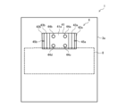
- FIG. 5 is a side view showing the compressor 1 according to the first embodiment.
- the container-side joint portion 44 is provided at a position shifted from the stator 8 in the first direction Z. That is, the container-side joint portion 44 is provided at a position that does not overlap with the stator 8 in the first direction Z.
- the base portion 41 is provided at a position partially overlapping the stator 8 in the first direction Z. Specifically, only the lower end portion of the base portion 41 where the container side joint portion 44 is not provided overlaps with the upper end portion of the stator 8.
- FIG. 6 is a side view showing the compressor 1 according to the first embodiment. Next, the position of the muffler side joint portion 45 will be explained. As shown in FIG. 6, the muffler side joint portion 45 is provided at a position shifted from the stator 8 in the first direction Z. That is, the muffler side joint portion 45 is provided at a position that does not overlap with the stator 8 in the first direction Z.
- the container-side joint portion 44 of the base portion 41 of the fixture 4 is provided at a position shifted from the stator 8 in the first direction Z. Therefore, even if the vibrations generated by the stator 8 propagate to the closed container 3, the vibrations propagated to the closed container 3 are difficult to propagate to the suction muffler 2 via the fixture 4. Thereby, it is possible to suppress vibrations from propagating to the refrigerant pipe 12b. Therefore, generation of abnormal noise can be suppressed.
- the container-side joint portion 44 is provided at a position that does not overlap with the stator 8 in the first direction Z. Therefore, vibrations generated by the stator 8 can be suppressed from propagating to the suction muffler 2, compared to the case where the container-side joint portion 44 is provided at a position overlapping the stator 8.
- the base portion 41 is provided at a position that faces the closed container 3 and partially overlaps the stator 8 in the first direction Z. Therefore, the space for arranging the components constituting the compressor 1 in the first direction Z can be reduced. Therefore, the length of the compressor 1 in the first direction Z can be shortened. In addition, even if a part of the base part 41 overlaps with the stator 8, since the container-side joint part 44 is provided at a position that does not overlap with the stator 8 in the first direction Z, the vibration generated by the stator 8 can be suppressed from propagating to the suction muffler 2.
- the contact part 42 is joined to the suction muffler 2, is provided at a position shifted from the stator 8 in the first direction Z, and has a muffler side joint part 45 that protrudes toward the suction muffler 2 side.
- a compressor in which a closed container and a suction muffler are fixed via a suction muffler fixing fitting.
- the eigenvalue decreases and vibration increases compared to when a copper wire is used as the conductor. Therefore, there is a risk that vibrations will propagate to the suction muffler via the closed container and the fixture.
- carbon dioxide is conventionally used as a refrigerant
- the operating pressure of the carbon dioxide refrigerant is approximately three times that of a common air conditioning refrigerant such as R32 or R410A.
- the torque fluctuations generated in the compression mechanism become large, and the generated vibrations may propagate to the suction muffler via the closed container and the fixing fittings.
- vibrations propagated to the suction muffler may be propagated to the suction pipe, causing abnormal noise or the like.
- the container-side joint portion 44 is provided at a position shifted from the stator 8 in the first direction Z. Therefore, even if an aluminum wire is used for the conductor of the stator 8 of the electric mechanism 7, propagation of vibration to the suction muffler 2 can be suppressed. Further, even if carbon dioxide is used as a refrigerant and the operating pressure increases, vibrations can be prevented from propagating to the suction muffler 2.
- FIG. 7 is a side view showing the fixture 4 according to the second embodiment.
- the second embodiment differs from the first embodiment in that a rib 11 is formed on the fixture 4.
- parts common to those in the first embodiment are given the same reference numerals and explanations are omitted, and differences from the first embodiment will be mainly explained.
- a concave rib 11 is formed in the fixing metal fitting 4 from the contact portion 42 to the extension portion 43.
- the rib 11 has a first rib 11a provided on the first extending portion 43a side and a second rib 11b provided on the second extending portion 43b side.
- the rib 11 is provided to ensure the strength of the fixture 4 itself, and has a rectangular shape.
- the rib 11 has two sides extending away from each other toward the contact portion 42 from a corner on the base side, and two sides extending toward the contact portion 42 from both corners toward each other. has been done.
- the portion where the two sides extending toward the contact portion 42 overlap is a corner portion on the contact portion 42 side.
- FIG. 8 is a side view showing the compressor 1 according to the second embodiment. As shown in FIG. 8, the rib 11 is provided at a position shifted from the stator 8 in the first direction Z. That is, the rib 11 is provided at a position that does not overlap the stator 8 in the first direction Z.
- the container-side joint 44 has an upper joint 50a and an equivalent joint 50b. At least a portion of the upper joint 50a is provided above the rib 11 in the first direction Z, and corresponds to the first container-side joint 44a and the second container-side joint 44b.
- the lower joint part is provided at the same position as the rib 11 in the first direction Z, and corresponds to the third container-side joint part 44c and the fourth container-side joint part 44d.
- the distance A between the first container-side joint 44a and the second container-side joint 44b is wider than the distance B between the third container-side joint 44c and the fourth container-side joint 44d. In this way, the distance A between the upper joints 50a is wider than the distance B between the lower joints.
- the concave rib 11 is formed in the fixing metal fitting 4 from the contact part 42 to the extension part 43, and the rib 11 is displaced from the stator 8 in the first direction Z. It is located in the same position. Therefore, even if vibrations generated from the stator 8 propagate to the closed container 3, the vibrations are difficult to propagate from the closed container 3 to the ribs 11. Therefore, propagation of vibration to the suction muffler 2 can be suppressed.
- the rib 11 is provided at a position that does not overlap the stator 8 in the first direction Z. Therefore, vibrations generated by the stator 8 can be suppressed from propagating to the suction muffler 2, compared to the case where the rib 11 is provided at a position overlapping the stator 8.
- the container side joint part 44 includes an upper joint part 50a provided above the rib 11 in the first direction Z, and an equivalent joint part 50b provided at the same position as the rib 11 in the first direction Z.
- the interval A between the plurality of upper joint parts 50a is wider than the interval B between the plurality of equivalent joint parts 50b.
- the interval A between the plurality of upper joint parts 50a is wider than the interval B between the plurality of equivalent joint parts 50b. Therefore, the fixture 4 can be fixed to the closed container 3 at a lower position than, for example, when welding is performed at a position that does not overlap the rib 11 in the first direction Z. Further, even if all of the equivalent joint portions 50b are provided at positions overlapping the ribs 11 in the first direction Z, the fixing fitting 4 and the airtight container 3 can be suitably fixed. Furthermore, propagation of vibrations can be suppressed.
Landscapes
- Engineering & Computer Science (AREA)
- Mechanical Engineering (AREA)
- General Engineering & Computer Science (AREA)
- Compressor (AREA)
Abstract
圧縮機は、第1方向に延びるように外郭を構成する密閉容器と、密閉容器の内部に設けられる固定子と、固定子によって回転する回転子とを有する電動機構と、電動機構に取り付けられ、電動機構の回転力を伝達するシャフトと、シャフトの回転に伴って回転して冷媒を圧縮する圧縮機構と、圧縮機構に冷媒を流入する吸入配管と、吸入配管に接続され、吸入配管に流れる冷媒から発生する音を抑制するサクションマフラーと、サクションマフラーと密閉容器とを接続する固定金具と、を備え、固定金具は、密閉容器に接合し、第1方向において固定子に対しずれた位置に設けられ、密閉容器側に突出する容器側接合部を有する基礎部と、基礎部の両端部から延びる延設部と、延設部の先端に設けられ、サクションマフラーに当接する当接部と、を有する。
Description
本開示は、密閉容器とサクションマフラーとを接続する固定金具を備える圧縮機及び冷凍サイクル装置に関する。
従来、吸入配管に接続され、吸入配管に流れる冷媒から発生する音を抑制するサクションマフラーを備える圧縮機が知られている。この場合、サクションマフラーは、固定金具を用いて密閉容器に固定されている。特許文献1には、密閉容器内にガス状の冷媒を圧縮する圧縮機構部と、圧縮機構部を駆動する電動機構部とを備えた圧縮機が開示されている。特許文献1は、密閉容器とサクションマフラーとが、サクションマフラー用の固定金具を介して固定されている。特許文献1の圧縮機は、密閉容器と固定金具とがプロジェクション溶接されて接合され、固定金具とサクションマフラーとがアーク溶接されて接合されることによって、密閉容器とサクションマフラーとが固定されている。
ここで、圧縮機構部及び電動機構部の振動がサクションマフラーに伝播すると、振動が冷媒配管に伝播することによって、冷媒配管の振動による異音が発生するおそれがある。特許文献1のような圧縮機においても、このような異音の発生を抑制することが望まれている。
本開示は、上述の課題を解決するものであり、異音の発生を抑制する圧縮機及び冷凍サイクル装置を提供することを目的とする。
本開示に係る圧縮機は、第1方向に延びるように外郭を構成する密閉容器と、密閉容器の内部に設けられる固定子と、固定子によって回転する回転子とを有する電動機構と、電動機構に取り付けられ、電動機構の回転力を伝達するシャフトと、シャフトの回転に伴って回転して冷媒を圧縮する圧縮機構と、圧縮機構に冷媒を流入する吸入配管と、吸入配管に接続され、吸入配管に流れる冷媒から発生する音を抑制するサクションマフラーと、サクションマフラーと密閉容器とを接続する固定金具と、を備え、固定金具は、密閉容器に接合し、第1方向において固定子に対しずれた位置に設けられ、密閉容器側に突出する容器側接合部を有する基礎部と、基礎部の両端部から延びる延設部と、延設部の先端に設けられ、サクションマフラーに当接する当接部と、を有する。
本開示によれば、固定金具の基礎部における容器側接合部は、第1方向において固定子に対しずれた位置に設けられている。このため、固定子によって発生する振動が密閉容器に伝播しても、密閉容器に伝播した振動が固定金具を介してサクションマフラーに伝播し難い。これにより、振動が冷媒配管に伝播することを抑制することができる。従って、異音の発生を抑制することができる。
以下、本開示の圧縮機及び冷凍サイクル装置の実施の形態について、図面を参照しながら説明する。なお、本開示は、以下に説明する実施の形態によって限定されるものではない。また、図1を含め、以下の図面では各構成部材の大きさの関係が実際のものとは異なる場合がある。また、以下の説明において、本開示の理解を容易にするために方向を表す用語を適宜用いるが、これは本開示を説明するためのものであって、これらの用語は本開示を限定するものではない。方向を表す用語としては、例えば、「上」、「下」、「右」、「左」、「前」又は「後」等が挙げられる。
実施の形態1.
[冷凍サイクル装置12の構成]
図1は、本実施の形態1に係る冷凍サイクル装置12を示す回路図である。冷凍サイクル装置12は、例えば給湯装置であり、図1に示すように、熱源機17と、利用機器18とを備えている。熱源機17には、例えば圧縮機1、第1の熱交換器13、膨張部15及び第2の熱交換器16が設けられている。
[冷凍サイクル装置12の構成]
図1は、本実施の形態1に係る冷凍サイクル装置12を示す回路図である。冷凍サイクル装置12は、例えば給湯装置であり、図1に示すように、熱源機17と、利用機器18とを備えている。熱源機17には、例えば圧縮機1、第1の熱交換器13、膨張部15及び第2の熱交換器16が設けられている。
圧縮機1、第1の熱交換器13、膨張部15及び第2の熱交換器16が冷媒配管12bにより接続されて冷媒回路12aが構成されている。圧縮機1は、低温且つ低圧の状態の冷媒を吸入し、吸入した冷媒を圧縮して高温且つ高圧の状態の冷媒にして吐出するものである。圧縮機1は、例えば容量制御可能なシングルロータリー式の圧縮機1である。第1の熱交換器13は、例えば水回路14aに流れる水と冷媒との間で熱交換するものであり、ガスクーラとして作用する。膨張部15は、冷媒を減圧して膨張する減圧弁又は膨張弁である。膨張部15は、例えば開度が調整される電子式膨張弁である。第2の熱交換器16は、例えば空気と冷媒との間で熱交換するものであり、蒸発器として作用する。
第2の熱交換器16及び利用機器18が水配管14bにより接続されて水回路14aが構成されている。第2の熱交換器16は、例えば冷媒回路12aに流れる冷媒と水との間で熱交換するものである。利用機器18は、熱源機17において生成された温熱を利用して給湯するものである。
[冷凍サイクル装置12の給湯運転]
次に、給湯運転について説明する。給湯運転において、圧縮機1に吸入された冷媒は、圧縮機1によって圧縮されて高温且つ高圧のガス状態で吐出する。圧縮機1から吐出された高温且つ高圧のガス状態の冷媒は、ガスクーラとして作用する第2の熱交換器16に流入し、第2の熱交換器16において、水回路14aに流れる水と熱交換されて凝縮して液化する。このとき、水回路14aに流れる水が暖められる。凝縮された液状態の冷媒は、膨張部15に流入し、膨張部15において膨張及び減圧されて低温且つ低圧の気液二相状態の冷媒となる。そして、気液二相状態の冷媒は、蒸発器として作用する第1の熱交換器13に流入し、第1の熱交換器13において、空気と熱交換されて蒸発してガス化する。蒸発した低温且つ低圧のガス状態の冷媒は、圧縮機1に吸入される。
次に、給湯運転について説明する。給湯運転において、圧縮機1に吸入された冷媒は、圧縮機1によって圧縮されて高温且つ高圧のガス状態で吐出する。圧縮機1から吐出された高温且つ高圧のガス状態の冷媒は、ガスクーラとして作用する第2の熱交換器16に流入し、第2の熱交換器16において、水回路14aに流れる水と熱交換されて凝縮して液化する。このとき、水回路14aに流れる水が暖められる。凝縮された液状態の冷媒は、膨張部15に流入し、膨張部15において膨張及び減圧されて低温且つ低圧の気液二相状態の冷媒となる。そして、気液二相状態の冷媒は、蒸発器として作用する第1の熱交換器13に流入し、第1の熱交換器13において、空気と熱交換されて蒸発してガス化する。蒸発した低温且つ低圧のガス状態の冷媒は、圧縮機1に吸入される。
なお、冷凍サイクル装置12は、給湯装置に限らず、床暖房装置でもよいし、空気調和装置等であってもよい。冷凍サイクル装置12が空機調和装置である場合、流路切替装置を有していれば、冷房運転及び暖房運転の両方を実施可能である。
[圧縮機1の構成]
図2は、本実施の形態1に係る圧縮機1を示す断面図である。次に、圧縮機1について詳細に説明する。図2に示すように、圧縮機1は、ローリングピストン型のシングルロータリー式圧縮機であり、内部に吸入した低圧のガス状態の冷媒を、高圧のガス状態の冷媒として吐出する流体機械である。圧縮機1の筐体は、シリンダ形状に形成された鉄製の密閉容器3によって構成されている。
図2は、本実施の形態1に係る圧縮機1を示す断面図である。次に、圧縮機1について詳細に説明する。図2に示すように、圧縮機1は、ローリングピストン型のシングルロータリー式圧縮機であり、内部に吸入した低圧のガス状態の冷媒を、高圧のガス状態の冷媒として吐出する流体機械である。圧縮機1の筐体は、シリンダ形状に形成された鉄製の密閉容器3によって構成されている。
密閉容器3は、第1方向Zに延びるように外郭を構成するものである。以下、上下方向を第1方向Zと呼称する。密閉容器3は、中空円筒形状の胴体部3aと、縦断面がU字形状の底部3bと、縦断面が逆U字形状の蓋部3cとにより構成され、底部3b及び蓋部3cの開口部の外側面は、胴体部3aの開口部の内側面に固定されている。胴体部3aと底部3bとの固定部分、及び、胴体部3aと蓋部3cとの固定部分は、例えばアーク溶接又は抵抗溶接等によって接合されている。密閉容器3の底部3bには、冷凍機油90が貯留している。
密閉容器3の胴体部3aの外側には、サクションマフラー2が配置されている。サクションマフラー2は、密閉容器3の外側面に配置された固定金具4を介して密閉容器3の胴体部3aに固定されている。サクションマフラー2は、上部容器2aと、下部容器2bとを有し、円筒形状を有している。上部容器2aと下部容器2bとは、例えば、溶接によって固定されている。サクションマフラー2を構成する上部容器2aの頂部には、吸入配管5が上部容器2aを貫通して固定されている。
吸入配管5は、低圧のガス状態の冷媒又は乾き度の高い二相状態の冷媒をサクションマフラー2の内部に流入させる冷媒配管12bである。また、サクションマフラー2を構成する下部容器2bの底部3bには、流入配管5aの一端が貫通して溶接等で固定されており、流入配管5aの他端は、密閉容器3の胴体部3aの側面部を貫通して固定されている。
サクションマフラー2は、アキュムレータ機能も有しており、余剰冷媒を貯留する冷媒貯留機能と、運転状態が変化する際に一時的に発生する液冷媒を滞留させることにより冷媒を気体と液体に分離する気液分離機能とを有している。また、サクションマフラー2は、吸入配管5から流入する冷媒により発生する騒音を低減又は除去する消音器としての機能も有している。サクションマフラー2の気液分離機能により、密閉容器3の内部に大量の液状態の冷媒が流入し、圧縮機1で液圧縮が行われるのを防ぐことができる。なお、密閉容器3とサクションマフラー2とを連結する固定金具4の詳細な構成については後述する。
流入配管5aは、低圧のガス状態の冷媒をサクションマフラー2から密閉容器3の内部に吸入させる冷媒配管12bである。密閉容器3の胴体部3aに形成された吸入穴5bには、固定部材5cが配置されており、流入配管5aは、吸入穴5bに配置された固定部材5cを介して、密閉容器3の胴体部3aに固定されている。
接続管6aは、一端側が吸入穴5bに挿入されており、密閉容器3の内部と連通している。流入配管5aは、固定部材5cの他端側に挿入されている。固定部材5cは、吸入穴5bに接合されており、接続管6aの外側面及び密閉容器3に接合され、流入配管5aと吸入穴5bとの間の隙間を密封している。圧縮機1は、固定部材5cによって、密閉容器3の内部の気密性が確保されている。
密閉容器3の蓋部3cの上面には、吐出配管6が貫通して固定されている。吐出配管6は、高圧のガス状態の冷媒を密閉容器3の外部に吐出させる冷媒配管12bである。吐出配管6と蓋部3cとの固定部分は、例えばろう付け又は抵抗溶接等によって接合されている。更に、密閉容器3の蓋部3cの上面には、ガラス端子60が配置されている。ガラス端子60は、外部電源(図示せず)と接続されるインタフェースを提供している。外部電源は、圧縮機1に電力を供給する電源装置であり、交流周波数が50Hz又は60Hzの一般商用交流電源、又は交流周波数を変化させることが可能なインバータ電源が用いられる。
密閉容器3の内部には、電動機構7と、シャフト70と、圧縮機構10とが収容されている。電動機構7は、密閉容器3における固定部材5cの配置位置より上方に配置されている。シャフト70は、密閉容器3の中心部において、電動機構7と圧縮機構10との間に配置され、電動機構7と圧縮機構10との間を上下方向に延びるように設けられている。圧縮機構10は、圧縮機構10の内部が流入配管5aと連通するように配置されている。すなわち、密閉容器3の内部においては、圧縮機構10の上方に電動機構7が配置されている。また、密閉容器3の内部の中空空間は、圧縮機構10で圧縮された高圧のガス状態の冷媒で満たされている。即ち、圧縮機1は、高圧シェルタイプである。
電動機構7は、外部電源から供給された電力を用いてシャフト70に回転駆動力を発生させ、シャフト70を介して圧縮機構10に回転駆動力を伝達するモータとして構成される。電動機構7は、上面視において中空円筒形状の外観を有する固定子8と、固定子8の内側面の内側に回転自在に配置された円筒状の回転子9とを備えている。固定子8は、焼き嵌め等により密閉容器3の胴体部3aの内側面に固定され、導線61を介してガラス端子60に接続されている。電動機構7は、外部電源から供給される電力が、固定子8を構成する巻回されたコイルに導線61を介して供給されることにより、固定子8の内側面の内側で回転子9を回転させることができる。圧縮機1においては、例えばDCブラシレスモータ等が電動機構7として用いられる。
回転子9の中心部には、シャフト70が回転子9を貫通して固定されている。シャフト70は、シャフト70の外側面の一部である固定面70aにて回転子9を固定し、圧縮機構10に回転子9の回転力を伝達する回転軸である。シャフト70は、固定面70aから上下方向、すなわち、密閉容器3の蓋部3cの方向と密閉容器3の底部3bの方向とに延びるように設けられている。
また、シャフト70は、固定面70aの下方に位置し、圧縮機構10の内部においてシリンダ73と対応する位置に配置される偏心部71を有している。偏心部71の外周には、偏心部71の外側面に沿って回転自在に取り付けられた略円筒状のピストン72が配置されている。ピストン72は、電動機構7によってシャフト70が回転すると、シリンダ73内をその内周面に沿って回転する。
また、圧縮機1は、シャフト70の下端部に遠心ポンプ(図示は省略)を配置してもよい。遠心ポンプは、密閉容器3の底部3bに貯留された冷凍機油90を吸い上げることができる。なお、冷凍機油90としては、例えば、鉱油系、アルキルベンゼン系、ポリアルキレングリコール系、ポリビニルエーテル系、ポリオールエステル系の潤滑油等が用いられる。
圧縮機構10は、電動機構7から供給された回転駆動力により、流入配管5aから密閉容器3の低圧空間に吸入された低圧のガス状態の冷媒を高圧のガス状態の冷媒に圧縮し、圧縮した高圧のガス状態の冷媒を圧縮機構10の上方に吐出するものである。
圧縮機構10は、中空円筒形状のシリンダ73を備えている。シリンダ73の外側面は、アークスポット溶接等のアーク溶接又は焼き嵌めによって、密閉容器3の胴体部3aの内側面に固定されている。シリンダ73の内側面に取り囲まれて構成された中空部分の空間には、シャフト70の偏心部71及びピストン72が収容されている。シリンダ73は、シリンダ73の中空部分において、シャフト70の回転により、シャフト70の偏心部71及びピストン72が偏心回転できるように構成されている。シリンダ73には、シリンダ73に形成された溝内を径方向に往復運動するベーン74の一端がピストン72のマフラ外周壁2cに当接することで圧縮室が形成されている。
シリンダ73の軸方向両端の開口部は、上軸受75及び下軸受76によって閉塞されている。すなわち、シリンダ73の上側には上軸受75が配置されており、シリンダ73の下側には下軸受76が配置されている。上軸受75、シリンダ73及び下軸受76には、シャフト70が貫通している。上軸受75及び下軸受76は、シャフト70を摺動自在に支持するすべり軸受であり、シャフト70を回転自在に支持している。上軸受75、シリンダ73及び下軸受76は、この順に積層され、シリンダ73の中空部分の上下開口を上軸受75と下軸受76とにより塞ぐことによって、中空部分内の気密性が確保されている。上軸受75及び下軸受76は、例えば、ボルト等によりシリンダ73の上側及び下側に固定されている。
圧縮機構10において、ピストン72、シリンダ73、ベーン74、上軸受75、及び下軸受76に囲まれた密閉自在な空間は、流入配管5aから吸入された低圧のガス状態の冷媒を圧縮する圧縮室を構成する。
本実施の形態1では、圧縮機1を縦置型の圧縮機として構成しているが、横置型の圧縮機として構成してもよい。また、本実施の形態1では、圧縮機1をローリングピストン型のロータリー式圧縮機として構成しているが、スイングベーン方式のスイング圧縮機として構成しても、スクリュ圧縮機又はスクロール圧縮機として構成してもよい。また、本実施の形態1では、シングルロータリー式のロータリー圧縮機として構成しているが、ツインロータリ式のロータリー圧縮機として構成してもよい。また、本実施の形態1では、圧縮機1を単段圧縮機とし、圧縮機構10を1つのみ有する構成としているが、圧縮機1を多段圧縮機とし、複数の圧縮機構10によって冷媒を順次圧縮する構成としてもよい。
[圧縮機1の動作]
次に、本実施の形態1の圧縮機1の動作について説明する。電動機構7の駆動によりシャフト70が回転すると、シャフト70と共に、シリンダ73の内部に収容された偏心部71及びピストン72が偏心回転する。ピストン72は、偏心部71及びピストン72の偏心回転によって、ピストン72の外周面をシリンダ73の中空部分におけるシリンダ73の内側面に接触させながら移動する。シリンダ73に配置されたベーン74は、ピストン72の偏心回転と連動してシリンダ73の径方向にピストン72運動する。
次に、本実施の形態1の圧縮機1の動作について説明する。電動機構7の駆動によりシャフト70が回転すると、シャフト70と共に、シリンダ73の内部に収容された偏心部71及びピストン72が偏心回転する。ピストン72は、偏心部71及びピストン72の偏心回転によって、ピストン72の外周面をシリンダ73の中空部分におけるシリンダ73の内側面に接触させながら移動する。シリンダ73に配置されたベーン74は、ピストン72の偏心回転と連動してシリンダ73の径方向にピストン72運動する。
サクションマフラー2を通って流入配管5aから圧縮機構10に流入した低圧のガス状態の冷媒は、ピストン72、シリンダ73、ベーン74、上軸受75、及び、下軸受76に囲まれた密閉空間である圧縮室に流入する。圧縮室の内部に流入した低圧のガス状態の冷媒は、ピストン72の偏心回転による圧縮室の容積の減少に伴い、高圧のガス状態の冷媒に圧縮される。高圧のガス状態の冷媒は、上軸受75に設けられた吐出口(図示は省略)を介して、密閉容器3の内部の中空空間に吐出される。密閉容器3の内部の中空空間に吐出された高圧のガス状態の冷媒は、例えば、電動機構7の固定子8と回転子9との間の隙間等を通過し、吐出配管6を介して密閉容器3の外へと吐出される。
[固定金具4の詳細]
図3は、本実施の形態1に係る固定金具4を示す上面図であり、図2の密閉容器3とサクションマフラー2との間に固定された固定金具4の上面視における概略図である。図4は、本実施の形態1に係る固定金具4を示す側面図である。図3及び図4を用いて、固定金具4について詳細に説明する。
図3は、本実施の形態1に係る固定金具4を示す上面図であり、図2の密閉容器3とサクションマフラー2との間に固定された固定金具4の上面視における概略図である。図4は、本実施の形態1に係る固定金具4を示す側面図である。図3及び図4を用いて、固定金具4について詳細に説明する。
固定金具4は、圧縮機1の密閉容器3にサクションマフラー2を固定するものである。固定金具4は、金属製の板材であり、例えば、プレス加工で成形される。固定金具4は、基礎部41と、延設部43と、当接部42とを有する。固定金具4は、基礎部41と、当接部42と、延設部43と、後述する容器側接合部44及びマフラ側接合部45とが、プレス加工された1枚の板材から形成されている。
[基礎部41]
基礎部41は、固定金具4において、圧縮機1の密閉容器3の胴体部3aの容器外周壁3a1に取り付けられて固定される部分である。基礎部41は、正面視で矩形の板状の部分であり、上面視で密閉容器3の容器外周壁3a1の周方向に沿って湾曲した形状に形成されている部分である。板状に形成された基礎部41は、基礎部41を構成する壁の表面と裏面とを構成する第1対向面部41aと第2対向面部41bとを有する。第1対向面部41aは、圧縮機1において、密閉容器3と対向する面を構成する。第2対向面部41bは、圧縮機1において、サクションマフラー2と対向する面を構成する。
基礎部41は、固定金具4において、圧縮機1の密閉容器3の胴体部3aの容器外周壁3a1に取り付けられて固定される部分である。基礎部41は、正面視で矩形の板状の部分であり、上面視で密閉容器3の容器外周壁3a1の周方向に沿って湾曲した形状に形成されている部分である。板状に形成された基礎部41は、基礎部41を構成する壁の表面と裏面とを構成する第1対向面部41aと第2対向面部41bとを有する。第1対向面部41aは、圧縮機1において、密閉容器3と対向する面を構成する。第2対向面部41bは、圧縮機1において、サクションマフラー2と対向する面を構成する。
[容器側接合部44]
基礎部41には、密閉容器3との固定に用いられるプロジェクション溶接用の容器側接合部44が設けられている。容器側接合部44は、半球状の突起である。図4に示すように、容器側接合部44は、密閉容器3と対向する第1対向面部41aから膨出するように形成されている。容器側接合部44は、4つの突起を有する。第1容器側接合部44a、第2容器側接合部44b、第3容器側接合部44c、第4容器側接合部44dは、上下方向に分かれて2つずつ、周方向に分かれて2つずつ配置されており、仮想の矩形状において4つの角部のそれぞれに位置するように配置されている。ただし、容器側接合部44の形成数は、4つに限定されるものではない。
基礎部41には、密閉容器3との固定に用いられるプロジェクション溶接用の容器側接合部44が設けられている。容器側接合部44は、半球状の突起である。図4に示すように、容器側接合部44は、密閉容器3と対向する第1対向面部41aから膨出するように形成されている。容器側接合部44は、4つの突起を有する。第1容器側接合部44a、第2容器側接合部44b、第3容器側接合部44c、第4容器側接合部44dは、上下方向に分かれて2つずつ、周方向に分かれて2つずつ配置されており、仮想の矩形状において4つの角部のそれぞれに位置するように配置されている。ただし、容器側接合部44の形成数は、4つに限定されるものではない。
[延設部43]
延設部43は、固定金具4において、基礎部41と当接部42とを繋ぐ部分である。延設部43は、密閉容器3の周方向において、基礎部41の両端部から立ち上がるように設けられている。延設部43は、圧縮機1において、密閉容器3とサクションマフラー2との間を延びるように設けられている。延設部43は、基礎部41の端部から屈曲して基礎部41と一体に形成されている。また、延設部43は、基礎部41と連続して板状部材として形成されている。
延設部43は、固定金具4において、基礎部41と当接部42とを繋ぐ部分である。延設部43は、密閉容器3の周方向において、基礎部41の両端部から立ち上がるように設けられている。延設部43は、圧縮機1において、密閉容器3とサクションマフラー2との間を延びるように設けられている。延設部43は、基礎部41の端部から屈曲して基礎部41と一体に形成されている。また、延設部43は、基礎部41と連続して板状部材として形成されている。
延設部43は、第1延設部43aと第2延設部43bとを有する。第1延設部43aは、密閉容器3の周方向において、基礎部41が延びる方向の一方の端部である第1端部41cから延びるように形成されている。第2延設部43bは、密閉容器3の周方向において、基礎部41が延びる方向の他方の端部である第2端部41dから延びるように形成されている。第1延設部43aと基礎部41とは、上面視でL字形状に形成されており、第2延設部43bと基礎部41とは、上面視で逆L字形状に形成されている。
第1延設部43aと第2延設部43bとは、図4に示すように、基礎部41から先端側に向かうに従って、互いの間の距離が広がるように形成されている。なお、第1延設部43aと第2延設部43bとは、基礎部41から先端側に向かうに従って、互いの間の距離が広がるように形成されたものに限定されない。たとえば、第1延設部43aと第2延設部43bとは、基礎部41から立ち上がり延びる方向に向かって、互いに平行となるように形成されてもよい。延設部43は、基礎部41と当接部42との間に配置され、基礎部41と当接部42とを繋ぐ役割を果たす。すなわち、延設部43は、基礎部41から立ち上がり延びる方向において、一方の端部側に基礎部41を有し、他方の端部側に当接部42を有する。
[当接部42]
当接部42は、固定金具4において、円筒形状のサクションマフラー2のマフラ外周壁2cに取り付けられて固定される部分である。当接部42は、上面視において、基礎部41から立ち上がって延びる延設部43の先端側の端部に設けられている。当接部42は、延設部43の端部から屈曲して延設部43と一体に形成されている。また、当接部42は、延設部43と連続して板状部材として形成されている。当接部42は、サクションマフラー2側から見た正面視で矩形の板状の部材であり、上面視でサクションマフラー2のマフラ外周壁2cの周方向に沿って湾曲した形状に形成されている。
当接部42は、固定金具4において、円筒形状のサクションマフラー2のマフラ外周壁2cに取り付けられて固定される部分である。当接部42は、上面視において、基礎部41から立ち上がって延びる延設部43の先端側の端部に設けられている。当接部42は、延設部43の端部から屈曲して延設部43と一体に形成されている。また、当接部42は、延設部43と連続して板状部材として形成されている。当接部42は、サクションマフラー2側から見た正面視で矩形の板状の部材であり、上面視でサクションマフラー2のマフラ外周壁2cの周方向に沿って湾曲した形状に形成されている。
当接部42は、プロジェクション溶接によって、サクションマフラー2のマフラ外周壁2cに固定されている。当接部42は、サクションマフラー2のマフラ外周壁2cと対向する第3対向面部42c及び第4対向面部42dが、マフラ外周壁2cと密着していることが望ましいが、マフラ外周壁2cとの間に隙間が形成されてもその隙間は1mm以下である。なお、第3対向面部42c及び第4対向面部42dについては後述する。
当接部42は、基礎部41を挟んで両側に配置される第1当接部42aと第2当接部42bとを有する。第1当接部42aは、第1延設部43aが延びる方向の先端部である第3端部43cから延びるように形成されている。第2当接部42bは、第2延設部43bが延びる方向の先端部である第4端部43dから延びるように形成されている。第1当接部42aと第1延設部43aとは、上面視で逆L字形状に形成されており、第2当接部42bと第2延設部43bとは、上面視でL字形状に形成されている。第1当接部42aと第2当接部42bとは、図4に示すように、基礎部41側である延設部43から先端側に向かうに従って、互いの間の距離が広がるように形成されている。また、第1当接部42aと第2当接部42bとは、サクションマフラー2のマフラ外周壁2cにおいて、密閉容器3側の半円筒部分の湾曲面と対向して取り付けられている。
[マフラ側接合部45]
当接部42には、サクションマフラー2との固定に用いられるアーク溶接用のマフラ側接合部45が設けられている。マフラ側接合部45は、延設部43から当接部42の先端部の間に設けられた線形状の突起である。マフラ側接合部45は、サクションマフラー2の軸方向である第1方向Zに対して垂直に延びるように形成されている。また、マフラ側接合部45は、延びる方向に対する垂直断面において、サクションマフラー2側に膨出するように湾曲した形状に形成されている。なお、マフラ側接合部45の延びる方向は、サクションマフラー2の軸方向である第1方向Zと垂直なねじれの位置にあるように形成されている。
当接部42には、サクションマフラー2との固定に用いられるアーク溶接用のマフラ側接合部45が設けられている。マフラ側接合部45は、延設部43から当接部42の先端部の間に設けられた線形状の突起である。マフラ側接合部45は、サクションマフラー2の軸方向である第1方向Zに対して垂直に延びるように形成されている。また、マフラ側接合部45は、延びる方向に対する垂直断面において、サクションマフラー2側に膨出するように湾曲した形状に形成されている。なお、マフラ側接合部45の延びる方向は、サクションマフラー2の軸方向である第1方向Zと垂直なねじれの位置にあるように形成されている。
マフラ側接合部45は、例えば、プレス加工等で当接部42に形成される。マフラ側接合部45は、固定金具4において第1マフラ側接合部45a及び第2マフラ側接合部45bの2つ形成されている。第1マフラ側接合部45aは、第1当接部42aにおいて、サクションマフラー2のマフラ外周壁2cと対向する第3対向面部42cから膨出するように形成されている。第1当接部42aは、サクションマフラー2のマフラ外周壁2cと対向する第3対向面部42cがマフラ外周壁2cの周方向に沿う湾曲した形状に形成されている。第3対向面部42cには、マフラ外周壁2cとのアーク溶接に用いられる少なくとも1つ以上の突出した第1マフラ側接合部45aが形成されている。
第2マフラ側接合部45bは、第2当接部42bにおいて、サクションマフラー2のマフラ外周壁2cと対向する第4対向面部42dから膨出するように形成されている。第2当接部42bは、サクションマフラー2のマフラ外周壁2cと対向する第4対向面部42dがマフラ外周壁2cの周方向に沿う湾曲した形状に形成されている。第4対向面部42dには、マフラ外周壁2cとのアーク溶接に用いられる少なくとも1つ以上の突出した第2マフラ側接合部45bが形成されている。マフラ側接合部45は、第3対向面部42c及び第4対向面部42dから突出する高さが、当接部42の板厚未満の高さとなるように形成されている。
ただし、マフラ側接合部45の形成数は、2つに限定されるものではない。マフラ側接合部45は、第1当接部42a及び第2当接部42bのそれぞれに2つ以上形成されてもよい。
[容器側接合部44の位置]
図5は、本実施の形態1に係る圧縮機1を示す側面図である。次に、容器側接合部44の位置について説明する。図5に示すように、容器側接合部44は、第1方向Zにおいて固定子8に対しずれた位置に設けられている。即ち、容器側接合部44は、第1方向Zにおいて固定子8と重ならない位置に設けられている。また、基礎部41は、第1方向Zにおいて固定子8に対し一部重なる位置に設けられている。具体的には、基礎部41のうち容器側接合部44が設けられていない下端部のみが、固定子8の上端部と重なっている。
図5は、本実施の形態1に係る圧縮機1を示す側面図である。次に、容器側接合部44の位置について説明する。図5に示すように、容器側接合部44は、第1方向Zにおいて固定子8に対しずれた位置に設けられている。即ち、容器側接合部44は、第1方向Zにおいて固定子8と重ならない位置に設けられている。また、基礎部41は、第1方向Zにおいて固定子8に対し一部重なる位置に設けられている。具体的には、基礎部41のうち容器側接合部44が設けられていない下端部のみが、固定子8の上端部と重なっている。
[マフラ側接合部45の位置]
図6は、本実施の形態1に係る圧縮機1を示す側面図である。次に、マフラ側接合部45の位置について説明する。図6に示すように、マフラ側接合部45は、第1方向Zにおいて固定子8に対しずれた位置に設けられている。即ち、マフラ側接合部45は、第1方向Zにおいて固定子8と重ならない位置に設けられている。
図6は、本実施の形態1に係る圧縮機1を示す側面図である。次に、マフラ側接合部45の位置について説明する。図6に示すように、マフラ側接合部45は、第1方向Zにおいて固定子8に対しずれた位置に設けられている。即ち、マフラ側接合部45は、第1方向Zにおいて固定子8と重ならない位置に設けられている。
本実施の形態1によれば、固定金具4の基礎部41における容器側接合部44は、第1方向Zにおいて固定子8に対しずれた位置に設けられている。このため、固定子8によって発生する振動が密閉容器3に伝播しても、密閉容器3に伝播した振動が固定金具4を介してサクションマフラー2に伝播し難い。これにより、振動が冷媒配管12bに伝播することを抑制することができる。従って、異音の発生を抑制することができる。このように、本実施の形態1は、容器側接合部44は、第1方向Zにおいて固定子8と重ならない位置に設けられている。このため、容器側接合部44が固定子8と重なる位置に設けられている場合に比べて、固定子8によって発生する振動がサクションマフラー2に伝播することを抑制することができる。
また、基礎部41は、密閉容器3に対向し、第1方向Zにおいて固定子8に対し一部重なる位置に設けられている。このため、圧縮機1を構成する部品の第1方向Zにおける配置スペースを少なくすることができる。従って、圧縮機1の第1方向Zの長さを短くすることができる。なお、基礎部41の一部が固定子8と重なっていても、容器側接合部44が第1方向Zにおいて固定子8と重ならない位置に設けられているため、固定子8によって発生する振動がサクションマフラー2に伝播することを抑制することができる。
当接部42は、サクションマフラー2に接合し、第1方向Zにおいて固定子8に対しずれた位置に設けられ、サクションマフラー2側に突出するマフラ側接合部45を有する。これにより、固定子8によって発生する振動が密閉容器3に伝播しても、密閉容器3に伝播した振動が、固定金具4の基礎部41、延設部43、当接部42及びその接着点である溶接部から、サクションマフラー2に伝播することをより抑制することができる。
従来、密閉容器とサクションマフラーとが、サクションマフラー用の固定金具を介して固定された圧縮機が知られている。この場合、電動機構の固定子の導線にアルミニウム線が使用されると、導線に銅線が使用されたものに比べて、固有値が減少して振動が増加する。このため、密閉容器及び固定金具を介して、振動がサクションマフラーに伝播するおそれがある。また、従来、冷媒として二酸化炭素が使用されると、二酸化炭素冷媒の動作圧力は、R32又はR410Aといった一般的な空調用冷媒の動作圧力に比べて約3倍となる。このため、圧縮機構において発生するトルク変動が大きくなって、発生する振動が密閉容器及び固定金具を介して、サクションマフラーに伝播するおそれがある。これにより、サクションマフラーに伝播した振動が、吸入配管に伝播して、異音等が発生するおそれがある。
これに対し、本実施の形態1は、容器側接合部44は、第1方向Zにおいて固定子8に対しずれた位置に設けられている。このため、電動機構7の固定子8の導線にアルミニウム線が使用されても、振動がサクションマフラー2に伝播することを抑制することができる。また、冷媒として二酸化炭素が使用されて動作圧力が増加しても、振動がサクションマフラー2に伝播することを抑制することができる。
実施の形態2.
図7は、本実施の形態2に係る固定金具4を示す側面図である。本実施の形態2は、固定金具4にリブ11が形成されている点で、実施の形態1と相違する。本実施の形態2では、実施の形態1と共通する部分は同一の符号を付して説明を省略し、実施の形態1との相違点を中心に説明する。
図7は、本実施の形態2に係る固定金具4を示す側面図である。本実施の形態2は、固定金具4にリブ11が形成されている点で、実施の形態1と相違する。本実施の形態2では、実施の形態1と共通する部分は同一の符号を付して説明を省略し、実施の形態1との相違点を中心に説明する。
[リブ11]
図7に示すように、固定金具4には、当接部42から延設部43にかけて凹状のリブ11が形成されている。リブ11は、第1延設部43a側に設けられた第1のリブ11a及び第2延設部43b側に設けられた第2のリブ11bを有している。リブ11は、固定金具4自体の強度を担保するために設けられるものであり、四角形状をなしている。リブ11は、基部側の角部から互いに離れるように当接部42側に延びるように2辺が形成され、両方の角部から互いに近付くように当接部42側に延びた2辺が形成されている。当接部42側に延びた2辺が重なる部分が当接部42側の角部となっている。
図7に示すように、固定金具4には、当接部42から延設部43にかけて凹状のリブ11が形成されている。リブ11は、第1延設部43a側に設けられた第1のリブ11a及び第2延設部43b側に設けられた第2のリブ11bを有している。リブ11は、固定金具4自体の強度を担保するために設けられるものであり、四角形状をなしている。リブ11は、基部側の角部から互いに離れるように当接部42側に延びるように2辺が形成され、両方の角部から互いに近付くように当接部42側に延びた2辺が形成されている。当接部42側に延びた2辺が重なる部分が当接部42側の角部となっている。
[リブ11の位置]
図8は、本実施の形態2に係る圧縮機1を示す側面図である。図8に示すように、リブ11は、第1方向Zにおいて固定子8に対しずれた位置に設けられている。即ち、リブ11は、第1方向Zにおいて固定子8と重ならない位置に設けられている。
図8は、本実施の形態2に係る圧縮機1を示す側面図である。図8に示すように、リブ11は、第1方向Zにおいて固定子8に対しずれた位置に設けられている。即ち、リブ11は、第1方向Zにおいて固定子8と重ならない位置に設けられている。
[容器側接合部44]
容器側接合部44は、上方接合部50aと同等接合部50bとを有している。上方接合部50aの少なくとも一部は、第1方向Zにおいてリブ11よりも上方に設けられたものであり、第1容器側接合部44a及び第2容器側接合部44bに相当する。下方接合部は、第1方向Zにおいてリブ11と同じ位置に設けられたものであり、第3容器側接合部44c及び第4容器側接合部44dに相当する。そして、第1容器側接合部44aと第2容器側接合部44bとの間の間隔Aは、第3容器側接合部44cと第4容器側接合部44dとの間の間隔Bよりも広い。このように、複数の上方接合部50a同士の間の間隔Aは、複数の下方接合部同士の間の間隔Bよりも広い。
容器側接合部44は、上方接合部50aと同等接合部50bとを有している。上方接合部50aの少なくとも一部は、第1方向Zにおいてリブ11よりも上方に設けられたものであり、第1容器側接合部44a及び第2容器側接合部44bに相当する。下方接合部は、第1方向Zにおいてリブ11と同じ位置に設けられたものであり、第3容器側接合部44c及び第4容器側接合部44dに相当する。そして、第1容器側接合部44aと第2容器側接合部44bとの間の間隔Aは、第3容器側接合部44cと第4容器側接合部44dとの間の間隔Bよりも広い。このように、複数の上方接合部50a同士の間の間隔Aは、複数の下方接合部同士の間の間隔Bよりも広い。
本実施の形態2によれば、固定金具4には、当接部42から延設部43にかけて凹状のリブ11が形成されており、リブ11は、第1方向Zにおいて固定子8に対しずれた位置に設けられている。このため、固定子8から発生する振動が密閉容器3に伝播しても、密閉容器3からリブ11に振動が伝播し難い。従って、振動がサクションマフラー2に伝播することを抑制することができる。このように、本実施の形態2は、リブ11が第1方向Zにおいて固定子8と重ならない位置に設けられている。このため、リブ11が固定子8と重なる位置に設けられている場合に比べて、固定子8によって発生する振動がサクションマフラー2に伝播することを抑制することができる。
また、容器側接合部44は、第1方向Zにおいてリブ11よりも上方に設けられた上方接合部50aと、第1方向Zにおいてリブ11と同じ位置に設けられた同等接合部50bと、を有する。そして、複数の上方接合部50a同士の間の間隔Aは、複数の同等接合部50b同士の間の間隔Bよりも広い。サクションマフラー2の長さが短い場合、固定金具4の位置が密閉容器3の低い位置に設けられる必要が生じる。
本実施の形態2は、複数の上方接合部50a同士の間の間隔Aは複数の同等接合部50b同士の間の間隔Bよりも広い。このため、例えばリブ11に対し第1方向Zにおいて重ならない位置において溶接が行われた場合と比較して低い位置で固定金具4を密閉容器3に固定することができる。また、同等接合部50bの全てが第1方向Zにおいてリブ11と重なる位置に設けられていても、固定金具4と密閉容器3とを好適に固定することができる。更に、振動の伝播を抑制することができる。
以上の実施の形態に示した構成は、一例を示すものであり、別の公知の技術と組み合わせることも可能であるし、要旨を逸脱しない範囲で、構成の一部を省略又は変更することも可能である。
1 圧縮機、2 サクションマフラー、2a 上部容器、2b 下部容器、2c マフラ外周壁、3 密閉容器、3a 胴体部、3a1 外周壁、3b 底部、3c 蓋部、4 固定金具、5 吸入配管、5a 流入配管、5b 吸入穴、5c 固定部材、6 吐出配管、7 電動機構、8 固定子、9 回転子、10 圧縮機構、11 リブ、11a 第1のリブ、11b 第2のリブ、12 冷凍サイクル装置、12a 冷媒回路、12b 冷媒配管、13 第1の熱交換器、14a 水回路、14b 水配管、15 膨張部、16 第2の熱交換器、17 熱源機、18 利用機器、41 基礎部、41a 第1対向面部、41b 第2対向面部、41c 第1端部、41d 第2端部、42 当接部、42a 第1当接部、42b 第2当接部、42c 第3対向面部、42d 第4対向面部、43 延設部、43a 第1延設部、43b 第2延設部、43c 第3端部、43d 第4端部、44 容器側接合部、44a 第1容器側接合部、44b 第2容器側接合部、44c 第3容器側接合部、44d 第4容器側接合部、45 マフラ側接合部、45a 第1マフラ側接合部、45b 第2マフラ側接合部、50a 上方接合部、50b 同等接合部、60 ガラス端子、61 導線、70 シャフト、70a 固定面、71 偏心部、72 ピストン、73 シリンダ、74 ベーン、75 上軸受、76 下軸受、90 冷凍機油。
Claims (7)
- 第1方向に延びるように外郭を構成する密閉容器と、
前記密閉容器の内部に設けられる固定子と、前記固定子によって回転する回転子とを有する電動機構と、
前記電動機構に取り付けられ、前記電動機構の回転力を伝達するシャフトと、
前記シャフトの回転に伴って回転して冷媒を圧縮する圧縮機構と、
前記圧縮機構に冷媒を流入する吸入配管と、
前記吸入配管に接続され、前記吸入配管に流れる冷媒から発生する音を抑制するサクションマフラーと、
前記サクションマフラーと前記密閉容器とを接続する固定金具と、を備え、
前記固定金具は、
前記密閉容器に接合し、前記第1方向において前記固定子に対しずれた位置に設けられ、前記密閉容器側に突出する容器側接合部を有する基礎部と、
前記基礎部の両端部から延びる延設部と、
前記延設部の先端に設けられ、前記サクションマフラーに当接する当接部と、を有する
圧縮機。 - 前記基礎部は、
前記密閉容器に対向し、前記第1方向において前記固定子に対し一部重なる位置に設けられている
請求項1記載の圧縮機。 - 前記当接部は、
前記サクションマフラーに接合し、前記第1方向において前記固定子に対しずれた位置に設けられ、前記サクションマフラー側に突出するマフラ側接合部を有する
請求項1又は2記載の圧縮機。 - 前記固定金具には、
前記当接部から前記延設部にかけて凹状のリブが形成されており、
前記リブは、
前記第1方向において前記固定子に対しずれた位置に設けられている
請求項1~3のいずれか1項に記載の圧縮機。 - 前記容器側接合部は、
前記第1方向において前記リブよりも上方に設けられた上方接合部と、
前記第1方向において前記リブと同じ位置に設けられた同等接合部と、を有する
請求項4記載の圧縮機。 - 複数の前記上方接合部同士の間の間隔は、
複数の前記同等接合部同士の間の間隔よりも広い
請求項5記載の圧縮機。 - 請求項1~6のいずれか1項に記載の圧縮機、第1の熱交換器、膨張部及び第2の熱交換器が冷媒配管により接続され、冷媒が流れる冷媒回路を備える
冷凍サイクル装置。
Priority Applications (2)
| Application Number | Priority Date | Filing Date | Title |
|---|---|---|---|
| JP2024520168A JP7774722B2 (ja) | 2022-05-12 | 2022-05-12 | 圧縮機及び冷凍サイクル装置 |
| PCT/JP2022/020021 WO2023218587A1 (ja) | 2022-05-12 | 2022-05-12 | 圧縮機及び冷凍サイクル装置 |
Applications Claiming Priority (1)
| Application Number | Priority Date | Filing Date | Title |
|---|---|---|---|
| PCT/JP2022/020021 WO2023218587A1 (ja) | 2022-05-12 | 2022-05-12 | 圧縮機及び冷凍サイクル装置 |
Publications (1)
| Publication Number | Publication Date |
|---|---|
| WO2023218587A1 true WO2023218587A1 (ja) | 2023-11-16 |
Family
ID=88730030
Family Applications (1)
| Application Number | Title | Priority Date | Filing Date |
|---|---|---|---|
| PCT/JP2022/020021 Ceased WO2023218587A1 (ja) | 2022-05-12 | 2022-05-12 | 圧縮機及び冷凍サイクル装置 |
Country Status (2)
| Country | Link |
|---|---|
| JP (1) | JP7774722B2 (ja) |
| WO (1) | WO2023218587A1 (ja) |
Citations (4)
| Publication number | Priority date | Publication date | Assignee | Title |
|---|---|---|---|---|
| JP2004293446A (ja) * | 2003-03-27 | 2004-10-21 | Mitsubishi Electric Corp | 密閉型圧縮機 |
| JP2011080377A (ja) * | 2009-10-05 | 2011-04-21 | Mitsubishi Electric Corp | 密閉型回転圧縮機 |
| JP2011127463A (ja) * | 2009-12-16 | 2011-06-30 | Denso Corp | 電動圧縮機 |
| WO2020202493A1 (ja) * | 2019-04-03 | 2020-10-08 | 三菱電機株式会社 | 固定金具、密閉型圧縮機、及び密閉型圧縮機の製造方法 |
-
2022
- 2022-05-12 JP JP2024520168A patent/JP7774722B2/ja active Active
- 2022-05-12 WO PCT/JP2022/020021 patent/WO2023218587A1/ja not_active Ceased
Patent Citations (4)
| Publication number | Priority date | Publication date | Assignee | Title |
|---|---|---|---|---|
| JP2004293446A (ja) * | 2003-03-27 | 2004-10-21 | Mitsubishi Electric Corp | 密閉型圧縮機 |
| JP2011080377A (ja) * | 2009-10-05 | 2011-04-21 | Mitsubishi Electric Corp | 密閉型回転圧縮機 |
| JP2011127463A (ja) * | 2009-12-16 | 2011-06-30 | Denso Corp | 電動圧縮機 |
| WO2020202493A1 (ja) * | 2019-04-03 | 2020-10-08 | 三菱電機株式会社 | 固定金具、密閉型圧縮機、及び密閉型圧縮機の製造方法 |
Also Published As
| Publication number | Publication date |
|---|---|
| JPWO2023218587A1 (ja) | 2023-11-16 |
| JP7774722B2 (ja) | 2025-11-21 |
Similar Documents
| Publication | Publication Date | Title |
|---|---|---|
| JP5117503B2 (ja) | 多気筒回転式圧縮機及び冷凍サイクル装置 | |
| CN103782036B (zh) | 具有两个气缸的旋转式压缩机 | |
| JP6548915B2 (ja) | 圧縮機 | |
| JP7520226B2 (ja) | 圧縮機 | |
| JP7774722B2 (ja) | 圧縮機及び冷凍サイクル装置 | |
| WO2020202493A1 (ja) | 固定金具、密閉型圧縮機、及び密閉型圧縮機の製造方法 | |
| JP2023037549A (ja) | スクロール圧縮機及び冷凍サイクル装置 | |
| WO2021106198A1 (ja) | 圧縮機および冷凍サイクル装置 | |
| JP6710348B1 (ja) | 圧縮機及びこの圧縮機を備えた空気調和機 | |
| JP2005054652A (ja) | 密閉型圧縮機 | |
| JP2017172346A (ja) | スクロール圧縮機、及び、空気調和機 | |
| WO2020183605A1 (ja) | 圧縮機及び冷凍サイクル装置 | |
| JP2017145795A (ja) | スクロール圧縮機及びそれを備えた空気調和装置 | |
| JP7469679B2 (ja) | スクロール圧縮機、および、それを備える冷凍サイクル装置 | |
| JP2022012527A (ja) | スクロール圧縮機、熱源ユニット | |
| KR102839986B1 (ko) | 압축기용 어큐뮬레이터 고정정치 및 이를 구비한 압축기 | |
| CN204783675U (zh) | 旋转压缩机及具有其的冷冻循环装置 | |
| JP3754213B2 (ja) | 回転式圧縮機 | |
| JP7376840B2 (ja) | インジェクション管を有する圧縮機 | |
| US20250109748A1 (en) | Hermetic compressor and refrigeration cycle apparatus | |
| JP5641801B2 (ja) | 冷媒圧縮機 | |
| JP2008008165A (ja) | 圧縮機 | |
| JP3291471B2 (ja) | 回転式圧縮機 | |
| WO2024218928A1 (ja) | 圧縮機及び冷凍サイクル装置 | |
| KR20090012866A (ko) | 로터리식 압축기 |
Legal Events
| Date | Code | Title | Description |
|---|---|---|---|
| 121 | Ep: the epo has been informed by wipo that ep was designated in this application |
Ref document number: 22941667 Country of ref document: EP Kind code of ref document: A1 |
|
| WWE | Wipo information: entry into national phase |
Ref document number: 2024520168 Country of ref document: JP |
|
| NENP | Non-entry into the national phase |
Ref country code: DE |
|
| 122 | Ep: pct application non-entry in european phase |
Ref document number: 22941667 Country of ref document: EP Kind code of ref document: A1 |