WO2023218569A1 - エンドエフェクタ - Google Patents
エンドエフェクタ Download PDFInfo
- Publication number
- WO2023218569A1 WO2023218569A1 PCT/JP2022/019978 JP2022019978W WO2023218569A1 WO 2023218569 A1 WO2023218569 A1 WO 2023218569A1 JP 2022019978 W JP2022019978 W JP 2022019978W WO 2023218569 A1 WO2023218569 A1 WO 2023218569A1
- Authority
- WO
- WIPO (PCT)
- Prior art keywords
- opening
- moving member
- closing
- contact
- treatment
- Prior art date
- Legal status (The legal status is an assumption and is not a legal conclusion. Google has not performed a legal analysis and makes no representation as to the accuracy of the status listed.)
- Ceased
Links
Images







Classifications
-
- B—PERFORMING OPERATIONS; TRANSPORTING
- B25—HAND TOOLS; PORTABLE POWER-DRIVEN TOOLS; MANIPULATORS
- B25J—MANIPULATORS; CHAMBERS PROVIDED WITH MANIPULATION DEVICES
- B25J15/00—Gripping heads and other end effectors
- B25J15/02—Gripping heads and other end effectors servo-actuated
- B25J15/0206—Gripping heads and other end effectors servo-actuated comprising articulated grippers
- B25J15/0226—Gripping heads and other end effectors servo-actuated comprising articulated grippers actuated by cams
-
- B—PERFORMING OPERATIONS; TRANSPORTING
- B25—HAND TOOLS; PORTABLE POWER-DRIVEN TOOLS; MANIPULATORS
- B25J—MANIPULATORS; CHAMBERS PROVIDED WITH MANIPULATION DEVICES
- B25J15/00—Gripping heads and other end effectors
- B25J15/0028—Gripping heads and other end effectors with movable, e.g. pivoting gripping jaw surfaces
-
- A—HUMAN NECESSITIES
- A01—AGRICULTURE; FORESTRY; ANIMAL HUSBANDRY; HUNTING; TRAPPING; FISHING
- A01D—HARVESTING; MOWING
- A01D46/00—Picking of fruits, vegetables, hops, or the like; Devices for shaking trees or shrubs
- A01D46/30—Robotic devices for individually picking crops
-
- B—PERFORMING OPERATIONS; TRANSPORTING
- B25—HAND TOOLS; PORTABLE POWER-DRIVEN TOOLS; MANIPULATORS
- B25J—MANIPULATORS; CHAMBERS PROVIDED WITH MANIPULATION DEVICES
- B25J11/00—Manipulators not otherwise provided for
- B25J11/005—Manipulators for mechanical processing tasks
- B25J11/0055—Cutting
-
- B—PERFORMING OPERATIONS; TRANSPORTING
- B25—HAND TOOLS; PORTABLE POWER-DRIVEN TOOLS; MANIPULATORS
- B25J—MANIPULATORS; CHAMBERS PROVIDED WITH MANIPULATION DEVICES
- B25J9/00—Program-controlled manipulators
- B25J9/06—Program-controlled manipulators characterised by multi-articulated arms
-
- A—HUMAN NECESSITIES
- A01—AGRICULTURE; FORESTRY; ANIMAL HUSBANDRY; HUNTING; TRAPPING; FISHING
- A01G—HORTICULTURE; CULTIVATION OF VEGETABLES, FLOWERS, RICE, FRUIT, VINES, HOPS OR SEAWEED; FORESTRY; WATERING
- A01G3/00—Cutting implements specially adapted for horticultural purposes; Delimbing standing trees
- A01G3/02—Secateurs; Flower or fruit shears
Definitions
- the present invention relates to an end effector.
- Fruits such as strawberries and grapes, and green and yellow vegetables such as asparagus and tomatoes are more delicate and easily damaged than grains such as rice and wheat, and their unit prices are higher. These delicate and expensive crops are harvested by hand, one by one, to avoid damage during harvest. Therefore, harvesting fruits, green and yellow vegetables, etc. places a greater physical burden on producers compared to grains, etc., which can be harvested efficiently and on a large scale using harvesting machines such as combines. Harvesting work is physically taxing, so securing labor is difficult, and the burden on producers tends to increase. Therefore, a crop harvesting system using an articulated robot arm is known.
- the crop harvesting system is provided with a working device for harvesting crops, an image processing device, etc. at the tip of an articulated robot arm.
- the harvesting system uses an image processing device to specify the position of a crop to be harvested, and uses a working device to perform harvesting work.
- Patent Document 1 discloses a robot harvesting system in which a picking head (end effector) for harvesting crops is provided at the tip of an articulated robot arm.
- the end effector described in Patent Document 1 includes a hook that captures a crop to be harvested, a gripper that grips the crop, a cutter that cuts the crop, and a camera that identifies the crop.
- the robot harvesting system identifies the crops to be harvested from images taken by a camera.
- the robotic harvesting system moves the hook along a predetermined circular arc by the articulated robot arm in order to capture the stalk of the crop to be harvested by the hook.
- the stem that has come into contact with the rod-shaped portion of the hook is captured by the semicircular tip of the hook as the hook moves in an arcuate trajectory.
- the robot harvesting system uses the cutter to cut the stem captured by the hook, and also grips the crop using the gripper.
- the portion that captures the crop be configured as compactly as possible in order to suppress interference between the end effector and crops surrounding the crop to be harvested.
- the robot harvesting system described in Patent Document 1 is configured to capture crops to be harvested using the hook, which has a semicircular tip end portion of a rod-like member. In other words, the robot harvesting system suppresses interference between the crop to be harvested and surrounding crops by using a hook whose semicircular tip has a function of capturing the crop to be harvested.
- each axis of an articulated robot arm which is a working machine that moves an end effector, is linked with high precision in order to move the hook along an arcuate trajectory.
- the robotic harvesting system improves the capture rate of crops by interlocking the articulated robot arm with even higher precision.
- the accuracy of the articulated robot arm that moves the end effector affects the rate at which the end effector captures crops.
- the robot harvesting system detects changes in the environment with high precision, and uses an articulated robot arm to control the end effector with high precision. You need to move it.
- the robot harvesting system configured in this way can improve the capture rate of crops to be harvested by interlocking the multi-joint robot arms with high precision, but the movement speed of the end effector by the multi-joint robot arms is limited. becomes slower and the number of crops per unit time decreases. Further, in the robot harvesting system, the entire end effector including the hook is moved along an arcuate trajectory in order to capture the crops to be harvested. That is, in the robot harvesting system, there is a movement space around the crops to be harvested, through which the entire end effector passes. Therefore, in the robot harvesting system, there is a possibility that the end effector, which moves along an arcuate trajectory, may come into contact with crops, etc. located around the crops to be harvested in the moving space, and damage the crops.
- the present invention provides robustness so that the object can be captured and treated even when the surrounding environment changes, without increasing the accuracy of movement of the working machine that moves the end effector.
- the purpose is to provide an improved end effector.
- the present inventors have improved the capture rate of the target object while reducing the time to move the end effector and the energy to move the end effector without increasing the accuracy of movement of the work machine that moves the end effector.
- An end effector includes a main body member supported by a movable working machine, and an end effector that is provided on the main body member and contacts a part of a target object to move a treatment region of the target object to a treatment position.
- an object positioning mechanism including a contact moving member and an opening/closing member positioned at the treatment position, and a treatment mechanism provided on the main body member to perform treatment on the treatment site of the object positioned at the treatment position.
- the object positioning mechanism is rotatably supported with respect to the main body member about a first axis perpendicular to the front-rear direction with the front direction being a direction from the main body member to the treatment position, and the first axis a first contact moving member extending further forward than the second axis; and a second contact member rotatably supported relative to the main body member about a second axis perpendicular to the front-rear direction and extending further forward than the second axis.
- a moving member, a portion of the first contacting and moving member, and a portion of the second contacting and moving member are located inside the main body member, the first contacting and moving member, and the second contacting and moving member;
- the cylindrical opening/closing member supported by the main body member so as to be movable in the front-rear direction, and elasticity that applies a rotational force to the first contact moving member and the second contact moving member in a direction in which their tips are separated from each other.
- an opening/closing member moving mechanism that moves the opening/closing member in the front-rear direction between a rear position where the object is positioned at a treatment position and a front position located forward of the rear position.
- the first contacting and moving member intersects with the second contacting and moving member inside the opening/closing member when viewed in the first axial direction, and is located at a portion in front of the portion intersecting with the second contacting and moving member.
- the contact portion contacts the first contacted portion, which is a part of the inner circumferential surface of the opening/closing member, by the elastic restoring force of the elastic member.
- a portion of the second contacting and moving member in front of a portion intersecting with the first contacting and moving member is caused by the elastic restoring force of the elastic member to cause the inner periphery of the opening/closing member to It contacts a second contacted portion, which is a portion of the surface that faces the portion that the first contacting and moving member contacts.
- the first contacted portion of the inner peripheral surface applies a forward force to the first contact moving member.
- the first contacting and moving member is rotated in a direction approaching the second contacting and moving member, and the second contacted portion of the inner peripheral surface applies a forward force to the second contacting and moving member to make the second contact.
- the moving member is rotated in a direction approaching the first contact moving member.
- the end effector by moving the opening/closing member in which a portion of the first contact moving member and a portion of the second contact moving member are located from the rear position to the front position, the first contact moving member and the second contact moving member are moved.
- the contact moving member and the second contact moving member are moved in a direction toward each other.
- the angle formed by the first contact-moving member and the second contact-moving member with respect to the front-rear direction becomes smaller. Become.
- the angle of the first contact moving member and the second contact moving member with respect to the front-rear direction is determined by the position of the rotatably supported portion of the first contact moving member and the second contact moving member, and the opening/closing angle of the first contact moving member and the second contact moving member. It is determined by the contact position at which the member is in contact with the first contacting and moving member and the second contacting and moving member.
- the first contact moving member and the second contact moving member intersect inside the opening/closing member.
- the inclination in the front-rear direction of the first contact-moving member and the second contact-moving member that intersect within the opening/closing member increases compared to the inclination when they do not intersect within the opening/closing member. Therefore, when the opening/closing member is located at the rear position, the distance between the tip of the first contacting and moving member and the tip of the second contacting and moving member is equal to the distance between the first contacting and moving member and the second contacting and moving member. The distance is wider than the distance when the contact moving members do not intersect.
- the end effector may be configured such that when an object exists within a distance between the tip of the first contact and movement member and the tip of the second contact and movement member, the work machine does not have to move the entire end effector.
- the object can be captured by the first contacting and moving member and the second contacting and moving member. Therefore, the end effector may have lower movement accuracy than when the first contacting and moving member and the second contacting and moving member do not intersect.
- the end effector can perform treatment on the target object even if the state of the environment around the target object changes, without increasing the precision of movement of the working machine that moves the end effector. . That is, the end effector has increased robustness due to the first contacting and moving member and the second contacting and moving member. Furthermore, since the end effector captures the object without significantly moving the main body member, when capturing the object, interference with other objects and obstacles located around the object is avoided. Can be suppressed.
- the end effector of the present invention preferably includes the following configuration.
- the opening/closing member contacts the object together with the first contacted portion and the second contact moving member while being positioned at the front position by the opening/closing member moving mechanism.
- the first contact moving member, the second contact moving member, and the opening/closing member contact the object in a state where the opening/closing member is positioned at the front position.
- the first contacting and moving member and the second contacting and moving member contact the object from the front.
- the opening/closing member contacts the object from behind. Therefore, even if the end effector is misaligned with respect to the object, the first contact movement member, the second contact movement member, and the opening/closing member capture the object in a posture that allows the treatment mechanism to easily treat the object.
- the end effector of the present invention preferably includes the following configuration.
- the first contacting and moving member and the second contacting and moving member are supported so as to be movable in the front and rear directions with respect to the main body member.
- the object positioning mechanism includes a contact moving member that moves the first contact moving member and the second contact moving member in the front-rear direction between the treatment position and a capture position located rearward than the treatment position.
- the first contact moving member and the second contact moving member are moved together with the opening/closing member by the contact moving member moving mechanism when the opening/closing member is moved from the front position to the rear position by the opening/closing member moving mechanism. Moving from the capture position to the treatment position.
- the end effector causes the first contact-moving member and the second contact-moving member to contact the object from the front, and causes the opening/closing member to contact the object from the rear. Furthermore, the end effector moves the first contact moving member, the second contact moving member, and the opening/closing member that have been brought into contact with the object to a rear position, thereby positioning the object at the treatment position. Therefore, the end effector can move the object to the treatment position using the first contact movement member, the second contact movement member, and the opening/closing member while maintaining the object in a posture that allows easy treatment by the treatment mechanism. That is, the end effector draws the object from the capture position to the treatment position using the first contact movement member, the second contact movement member, and the opening/closing member, so that objects around the object located at the capture position and the treatment mechanism interference can be suppressed.
- the end effector moves the object in a state where the first contact movement member and the second contact movement member are closest to each other, the end effector moves the object around the object when positioning the object at the treatment position. Interference with other located objects and obstacles can be suppressed.
- the end effector of the present invention preferably includes the following configuration.
- the first contacting and moving member has a first claw portion bent toward the second contacting and moving member at its front end.
- the second contacting and moving member has a second claw portion bent toward the first contacting and moving member at its front end.
- the first claw portion and the second claw portion at least partially overlap when viewed in the axial direction of the first axis when the opening/closing member is positioned at the front position.
- the first claw part of the first contact moving member and the second claw part of the second contact moving member when viewed in the axial direction of the first axis, They are configured so that at least a portion thereof overlaps. That is, when the first contact-moving member and the second contact-moving member surround and capture the object, and when the first contact-moving member and the second contact-moving member position the captured object at the treatment position, The first claw part and the second claw part are located adjacent to each other in the first axial direction. Therefore, the end effector moves the object to the treatment position with the object supported by both the first claw part and the second claw part.
- the target object is along the rearward facing surface of the first claw part and the rearward facing surface of the second claw part, the object is positioned at the treatment position in a posture that facilitates treatment by the treatment mechanism. Further, in the target part, since the first claw part and the second claw part are engaged with each other, the target object is difficult to come off from the first claw part and the second claw part when moving the target object. Thereby, the target object captured by the first contacting and moving member and the second contacting and moving member is unlikely to escape and can be efficiently treated by the treatment mechanism.
- the end effector of the present invention preferably includes the following configuration.
- the first claw part and the second claw part have a pair of end surfaces in the axial direction of the first axis.
- the opening/closing member positioned at the front position, at least one of the first claw part and the second claw part has an end face closer to the outer peripheral surface of the opening/closing member among the pair of end faces, When viewed from the rear, it overlaps with the end surface of the cylindrical opening/closing member.
- At least one of the first claw part and the second claw part has an end surface closer to the outer circumferential surface of the opening/closing member that does not protrude outward from the outer circumferential surface of the opening/closing member when viewed from the rear. In this state, it overlaps the end surface of the opening/closing member. Therefore, when the end effector captures the object with the first contact moving member and the second contact moving member, at least one of the first claw portion and the second claw portion is configured to engage the object from the front.
- the opening/closing member contacts the object from behind. That is, the end effector pinches the object from the front and rear directions between at least one of the first claw part and the second claw part and the opening/closing member. Thereby, the end effector can position the object at the treatment position using the end surface of the opening/closing member, the first claw part, and the second claw part.
- the end effector of the present invention preferably includes the following configuration.
- the first contacting and moving member has a first guide portion that is curved in a direction away from the second contacting and moving member.
- the second contacting and moving member has a second guide portion that is curved in a direction away from the first contacting and moving member.
- the opening/closing member moving forward contacts the first guide member and the second guide member, thereby rotating the first contact moving member and the second contact moving member, respectively.
- the end effector is configured such that the distal end portion of the first contacting and moving member and the distal end of the second contacting and moving member are connected to each other by the outwardly curved first guide portion of the first contacting and moving member and the second guide portion of the second contacting and moving member.
- the gap between the two departments is widened.
- the end effector is configured such that the first contact moving member having the first guide portion and the second contact moving member having the second guide portion allow the first contact moving member and the second contact moving member to capture the target object. Range increases.
- connection As used herein, “attached,” “connected,” “coupled,” and/or their equivalents are used in a broad sense, including “direct and indirect” attachment; Includes both connections and combinations. Additionally, “connected” and “coupled” are not limited to physical or mechanical connections or couplings, but can include direct or indirect electrical connections or couplings.
- an end effector means a device that performs any treatment on an object.
- the end effector is attached to the tip of a working machine such as a robot arm.
- the end effector has a structure capable of treating an object, and includes various devices that enable the treatment.
- target object refers to a natural object, an artificial object, a virus, a living thing (animal, plant), etc., which is a target to be treated by an end effector.
- the target object means agricultural products, marine products, industrial products, livestock, insects, people, etc.
- the target object includes both a treatment region, which is a portion treated by the end effector, and a contacted region, which is contacted by the contact portion of the end effector in order to be moved to a treatment position.
- the target objects include, for example, fruit stalks, fruits, trunks, stems, branches, leaves, stalks, and living things of agricultural crops.
- treatment refers to an operation performed on an object by an end effector.
- the treatment includes, for example, physical processing of the object, such as grasping, suction, cutting, heating, cooling, marking, measurement, injection, photographing, stimulation, manipulation, inspection, detection, etc. of the object.
- the treatment mechanism refers to a mechanism that performs treatment on an object in an end effector.
- the treatment mechanism performs physical processing such as grasping, suction, cutting, heating, cooling, marking, measurement, injection, photographing, stimulation, manipulation, inspection, detection, etc. on the object.
- the treatment mechanism includes, for example, a gripping mechanism that grips the object, a suction mechanism that sucks the object, a cutting mechanism that cuts the object, a heating and cooling mechanism that heats and cools the object, and a marking mechanism on the object.
- the marking mechanism includes a marking mechanism for measuring the object, a measuring mechanism for measuring the object, and the like.
- object positioning mechanism refers to a mechanism that positions an object at a treatment position in an end effector.
- the object positioning mechanism has a function of capturing the object at a capture position. Further, the object positioning mechanism has a function of moving the captured object from the capture position to the treatment position. Further, the object positioning mechanism has a function of holding the object.
- a treatment site refers to a portion of an object that is treated by a treatment mechanism of an end effector.
- the treatment region may be different from the contact position that is contacted by the contact movement member of the object positioning mechanism, or may include a part of the contact position.
- a treatment position means a position in the end effector where a treatment mechanism treats a target object in the end effector.
- the treatment position is included in at least a portion of a movement space of a contact movement member of the end effector.
- the time and energy for moving the end effector can be reduced without increasing the precision of the movement of the work machine that moves the end effector, and the target object can be moved easily.
- the capture rate can be improved.
- FIG. 1 is a perspective view of an end effector according to the present invention.
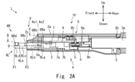
- FIG. 2A is a cross-sectional view of the end effector taken along line AA in FIG. 1.
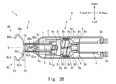
- FIG. 2B is a cross-sectional view of the end effector taken along line BB in FIG. 2A.
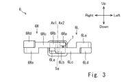
- FIG. 3 is a front view of the contact moving member moving mechanism of the end effector according to the present invention.
- FIG. 4 is a cross-sectional view taken along line BB in FIG. 2A when the end effector according to the present invention captures an object at a capture position.
- FIG. 5 is a cross-sectional view taken along line BB in FIG. 2A when the end effector according to the present invention moves the object to the treatment position.
- FIG. 1 is a perspective view of an end effector according to the present invention.
- FIG. 2A is a cross-sectional view of the end effector taken along line AA in FIG. 1.
- FIG. 2B is a cross-sectional view of the
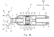
- FIG. 6A is a sectional view taken along line CC of the end effector in FIG. 2A when the contact moving member moving mechanism of the end effector according to the present invention is located at the capture position.
- FIG. 6B is a cross-sectional view taken along line AA in FIG. 1 when the contact moving member moving mechanism of the end effector according to the present invention is located at the capture position.
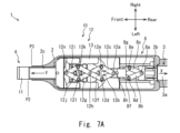
- FIG. 7A is a sectional view taken along line CC of the end effector in FIG. 2A when the contact moving member moving mechanism of the end effector according to the present invention has moved to the treatment position.
- FIG. 7B is a cross-sectional view taken along line AA in FIG. 1 when the contact moving member moving mechanism of the end effector according to the present invention moves to the treatment position.
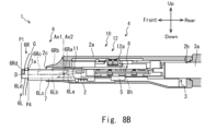
- FIG. 8A is a cross-sectional view of the end effector taken along line CC in FIG. 2A when the opening/closing member moves to the front position with the object positioning mechanism of the end effector according to the present invention located at the capture position.
- FIG. 8B is a cross-sectional view taken along line AA in FIG. 1 when the opening/closing member moves to the front position with the object positioning mechanism of the end effector according to the present invention located at the capture position.
- FIG. 9A is a perspective view of the contact moving member moving space in the contact moving member moving space of the end effector according to Embodiment 1 of the present invention.
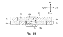
- FIG. 9B is a front view of the contact moving member in the contact moving member movement space of the end effector according to Embodiment 1 of the present invention.
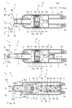
- FIG. 10 is a sectional view of the end effector taken along line CC in FIG. 2A when the contact moving member of the end effector according to Embodiment 1 of the present invention is located at the capturing position, and the contact moving member of the end effector is at the capturing position.
- FIG. 1 is a perspective view of an end effector 1 according to the present invention.
- FIG. 2A is a cross-sectional view of the end effector 1 taken along line AA in FIG. 1.
- FIG. 2B is a cross-sectional view of the end effector 1 taken along line BB in FIG. 2A.
- FIG. 3 is a front view of the contact moving member moving mechanism 6 of the end effector 1.
- FIG. 4 is a cross-sectional view taken along line BB in FIG. 2A when the end effector 1 captures the grape stalk G at the capture position P1.
- FIG. 5 is a cross-sectional view taken along line BB in FIG. 2A when the end effector 1 moves the grape stalk G to the treatment position P2.
- FIG. 6A is a cross-sectional view of the end effector 1 taken along line CC in FIG. 2A when the contact moving member moving mechanism 6 of the end effector 1 is located at the capture position P1.
- FIG. 6B is a sectional view taken along line AA in FIG. 1 when the contact moving member moving mechanism 6 of the end effector 1 is located at the capture position P1.
- FIG. 7A is a cross-sectional view of the end effector 1 taken along line CC in FIG. 2A when the contact moving member moving mechanism 6 of the end effector 1 moves to the treatment position P2.
- FIG. 7B is a sectional view taken along line AA in FIG. 1 when the contact moving member moving mechanism 6 of the end effector 1 moves to the treatment position P2.
- the arrow Front in the figure indicates the front direction of the end effector 1.
- the arrow Rear in the figure indicates the rear direction of the end effector 1.
- An arrow Up in the figure indicates the upward direction of the end effector 1.
- the arrow Down in the figure indicates the downward direction in the end effector 1.
- the front and back direction of the end effector 1 is the direction in which the direction in which the object positioning mechanism 4 moves toward the grape stalk G is the front direction of the end effector 1, that is, the direction in which the treatment blade 11 in the treatment mechanism 10 moves from the main body member 2. This is the direction of movement toward the treatment position P2.
- the left-right direction of the end effector 1 is a direction perpendicular to the front-back direction and the up-down direction of the end effector 1, when the vertical direction is defined as the up-down direction.
- clockwise means clockwise when viewed from above to below in the vertical direction.
- Counterclockwise means counterclockwise when viewed from above to below in the vertical direction.
- the end effector 1 is, for example, a device that harvests grapes by separating them from a fruit stalk G (see FIG. 4).
- the end effector 1 performs a treatment of cutting a treatment site Ta (see FIG. 6B) on the grape stalk G that is the target object using the treatment mechanism 10 (see FIG. 2A).
- the end effector 1 includes a main body member 2, an electric cylinder 3 that is an actuator, an object positioning mechanism 4 (see FIG. 2A), and a treatment mechanism 10.
- the main body member 2 is a component that constitutes the frame of the end effector 1.
- the main body member 2 is a substantially rectangular parallelepiped housing with one side open.
- the casing constituting the main body member 2 has a size that can accommodate the object positioning mechanism 4 and the treatment mechanism 10 therein.
- An electric cylinder 3, an object positioning mechanism 4, and a treatment mechanism 10 are housed inside the main body member 2 with the opening portion facing upward so that the longitudinal direction of the main body member 2 is along the front-rear direction. .
- a cover 2a is attached to the opening of the main body member 2 so as to close the opening.
- the rear surface of the main body member 2 has a rod insertion hole 2b into which the piston rod 3a of the electric cylinder 3 is inserted.
- the front surface of the main body member 2 has an opening/closing member insertion hole 2c into which the opening/closing member 7 of the object positioning mechanism 4 and the treatment blade 11 (see FIGS. 6A and 6B) of the treatment mechanism 10 are inserted.
- the opening/closing member insertion hole 2c extends forward from the front surface in a cylindrical shape.
- the electric cylinder 3 which is an actuator, is an actuator that moves the piston rod 3a in the axial direction by an electric motor 3b (see FIG. 1).
- the electric cylinder 3 includes an electric motor 3b and a piston rod 3a having a threaded portion.
- the electric motor 3b is configured to be able to reciprocate the piston rod 3a in the axial direction by rotating a movable core (not shown). In the electric cylinder 3, the moving direction of the piston rod 3a changes depending on the rotating direction of the movable core.
- the electric cylinder 3 is fixed to the rear surface of the main body member 2.
- the piston rod 3a of the electric cylinder 3 is inserted into the rod insertion hole 2b of the main body member 2.
- the piston rod 3a of the electric cylinder 3 is configured to be movable in the front-rear direction inside the main body member 2.
- the electric motor 3b of the electric cylinder 3 is configured to be fixed to a working machine that moves the end effector 1.
- the main body member 2 is configured to be supported by the working machine via an electric cylinder 3.
- the object positioning mechanism 4 is a mechanism for positioning the grape stalk G, which is the object.
- the object positioning mechanism 4 includes a connecting member 5, a contact moving member moving mechanism 6, an opening/closing member 7, an opening/closing member moving mechanism 8, and an opening/closing guide member 9.
- the connecting member 5 is a member that connects the opening/closing member 7 and the opening/closing member moving mechanism 8.
- the connecting member 5 is a rod-shaped member.
- the connecting member 5 is located within the main body member 2 so that the longitudinal direction of the connecting member 5 extends along the front-rear direction.
- the connecting member 5 is configured to be movable in the front-back direction.
- the rear end of the connecting member 5 is connected to the opening/closing intermediate shaft 8h of the opening/closing member moving mechanism 8.
- the front end of the connecting member 5 is located inside the opening/closing member 7.
- the front end of the connecting member 5 has a moving member support shaft 5a that rotatably supports a first contacting and moving member 6L and a second contacting and moving member 6R, which are contacting and moving members.
- the moving member support shaft 5a has an axis extending in a direction perpendicular to the front-back direction and the left-right direction.
- the contact moving member moving mechanism 6 is a mechanism that captures the target object, the grape stalk G (see FIG. 4).
- the contact moving member moving mechanism 6 includes a first contact moving member 6L and a second contact moving member 6R.
- the first contacting and moving member 6L and the second contacting and moving member 6R are members that capture the grape stalk G.
- the first contact moving member 6L and the second contact moving member 6R are curved rectangular plate members.
- the first contacting and moving member 6L and the second contacting and moving member 6R are constituted by members having sufficient rigidity that they do not undergo elastic deformation like a spring even if an external force is applied.
- the first contact moving member 6L is a member that approaches the fruit stalk G from the left side of the fruit stalk G by the forward movement of the opening/closing member 7.
- the first contact movement member 6L has a first bearing portion 6La, a first extension portion 6Lb, a first guide portion 6Lc, and a first claw portion 6Ld.
- the first contact moving member 6L is connected to each other in order from the first bearing portion 6La to a first extension portion 6Lb, a first guide portion 6Lc, and a first claw portion 6Ld.
- the first contact moving member 6L is integrally formed.
- the first bearing portion 6La is a cylindrical member into which the moving member support shaft 5a is inserted.
- the first extending portion 6Lb is a rectangular plate member.
- the first extending portion 6Lb is a straight portion whose one end portion is connected to the outer peripheral surface of the first bearing portion 6La as a base end portion.
- the first extending portion 6Lb is connected to the first bearing portion 6La so that the thickness direction thereof is perpendicular to the axis of the first bearing portion 6La.
- the first extending portion 6Lb extends in a direction perpendicular to the axial direction of the first bearing portion 6La.
- the first extending portion 6Lb is on the right side with respect to the axis when viewed in the axial direction. It extends forward from a position on the outer circumferential surface that is shifted in the direction.
- the first guide portion 6Lc is a rectangular plate member. One end of the first guide portion 6Lc is connected to the other end of the first extension portion 6Lb.
- the thickness direction of the first guide part 6Lc is orthogonal to the axis of the first bearing part 6La, when the axial direction of the first bearing part 6La is the up-down direction and the stretching direction of the first extension part 6Lb is the front direction. , it is a curved portion that bulges leftward from the other end of the first extending portion 6Lb.
- the first guide portion 6Lc has a first rib portion 6Le (see FIG. 3). In the first rib portion 6Le, the tip of the first guide portion 6Lc protrudes upward.
- the first guide portion 6Lc has improved rigidity at its tip by the first rib portion 6Le.
- the first claw portion 6Ld is a rectangular plate member. One end of the first claw portion 6Ld is connected to the other end of the first guide portion 6Lc.
- the first claw portion 6Ld has a pair of end surfaces on the upper side and the lower side in the axial direction of the first axis Ax1.
- the thickness direction of the first claw portion 6Ld is orthogonal to the axis of the first bearing portion 6La when the axial direction of the first bearing portion 6La is the up-down direction and the stretching direction of the first extension portion 6Lb is the front direction. , this is a claw portion bent toward the right from the other end of the first guide portion 6Lc.
- the first claw portion 6Ld is bent at an angle of about 90 degrees with respect to the first guide portion 6Lc.
- the moving member support shaft 5a of the connecting member 5 is inserted into the first bearing portion 6La. Therefore, the first contacting and moving member 6L is rotatable with respect to the main body member 2, with the axis of the moving member support shaft 5a being the first axis Ax1 (see FIGS. 2A and 3), which is the rotation center of the first contacting and moving member 6L. is supported by
- the first axis Ax1 is an axis extending in a direction perpendicular to the front-rear direction.
- the first contact moving member 6L is connected to the first bearing portion 6La in a state in which the first extending portion 6Lb extends forward along a reference line D that is perpendicular to the first axis Ax1 and extends in the front-rear direction.
- the end portion of the first extending portion 6Lb is supported by the moving member support shaft 5a so as to be located to the right of the reference line D.
- the second contact movement member 6R is a member that approaches the fruit stalk G from the right side of the fruit stalk G by the forward movement of the opening/closing member 7.
- the second contact movement member 6R includes a second bearing portion 6Ra, a second extension portion 6Rb, a second guide portion 6Rc, and a second claw portion 6Rd.
- the second contact movement member 6R is connected to each other in a sequence of a second extension part 6Rb, a second guide part 6Rc, and a second claw part 6Rd in order from the second bearing part 6Ra.
- the second contact moving member 6R is integrally formed.
- the second bearing portion 6Ra is a cylindrical member into which the moving member support shaft 5a is inserted.
- the second extending portion 6Rb is a rectangular plate member.
- the second extending portion 6Rb is a straight portion whose one end is connected to the outer circumferential surface of the second bearing portion 6Ra so that the thickness direction thereof is perpendicular to the axis of the second bearing portion 6Ra.
- the second extending portion 6Rb is connected to the second bearing portion 6Ra such that the thickness direction thereof is perpendicular to the axis of the second bearing portion 6Ra.
- the second extending portion 6Rb extends in a direction perpendicular to the axial direction of the second bearing portion 6Ra.
- the second extending part 6Rb is on the left side with respect to the axis when viewed in the axial direction. It extends forward from a position on the outer circumferential surface that is shifted in the direction.
- the second guide portion 6Rc is a rectangular plate member. One end of the second guide portion 6Rc is connected to the other end of the second extension portion 6Rb.
- the thickness direction of the second guide portion 6Rc is perpendicular to the axis of the second bearing portion 6Ra when the axial direction of the second bearing portion 6Ra is the up-down direction and the stretching direction of the second extension portion 6Rb is the front direction. , it is a curved portion that bulges out to the right from the other end of the second extending portion 6Rb.
- the second guide portion 6Rc has a second rib portion 6Re (see FIG. 3). In the second rib portion 6Re, the tip of the second guide portion 6Rc protrudes downward.
- the second guide portion 6Rc has improved rigidity at its tip by the second rib portion 6Re.
- the second claw portion 6Rd is a rectangular plate member. One end of the second claw portion 6Rd is connected to the other end of the second guide portion 6Rc.
- the second claw portion 6Rd has a pair of end surfaces on the upper side and the lower side in the axial direction of the first axis Ax1.
- the second claw part 6Rd moves leftward from the other end of the second guide part 6Rc. It is a curved claw part.
- the second claw portion 6Rd is bent at an angle of about 90 degrees with respect to the second guide portion 6Rc. Further, the upper end surface of the second claw portion 6Rd projects upward.
- the width of the second claw portion 6Rd in the vertical direction is larger than the width of the first claw portion 6Ld in the vertical direction due to the protruding portion.
- the moving member support shaft 5a of the connecting member 5 is inserted into the second bearing portion 6Ra. Therefore, the second contacting and moving member 6R is rotatable with respect to the main body member 2 with the axis of the moving member support shaft 5a as the second axis Ax2 (see FIGS. 2A and 3), which is the rotation center of the second contacting and moving member 6R. is supported by
- the second axis Ax2 is an axis extending in a direction perpendicular to the front-rear direction.
- the second bearing portion 6Ra is located above the first bearing portion 6La into which the moving member support shaft 5a is inserted.
- the second contacting and moving member 6R is rotatably supported by the moving member support shaft 5a above the first contacting and moving member 6L.
- the second contact movement member 6R is connected to the second bearing portion 6Ra in a state in which the second extending portion 6Rb extends forward along a reference line D that is perpendicular to the second axis Ax2 and extends in the front-rear direction.
- the end of the second extending portion 6Rb is supported by the moving member support shaft 5a so as to be located to the left of the reference line D.
- the first axis Ax1 and the second axis Ax2 are the same axis.
- the first bearing portion 6La and the second bearing portion 6Ra have torsion springs (not shown) that are elastic members that generate rotational force around the axis of the moving member support shaft 5a.
- the torsion spring applies a counterclockwise rotational force to the first bearing part 6La and a clockwise rotational force to the second bearing part 6Ra.
- the torsion spring applies a rotational force in a direction in which the first claw portion 6Ld located at the tip of the first contact moving member 6L and the second claw portion 6Rd located at the tip of the second contact moving member 6R move away from each other.
- the first contact moving member 6L is given a leftward rotational force by the elastic restoring force of the torsion spring.
- the second contact moving member 6R is given a rightward rotational force by the elastic restoring force of the torsion spring.
- the first extending portion 6Lb and the second extending portion 6Rb It is located inside the cylindrical opening/closing member 7 facing forward.
- the first contact moving member 6L and the second contact moving member 6R extend from the opening/closing member insertion hole 2c to the outside of the main body member 2 via the opening/closing member 7. Due to the elastic restoring force of the torsion spring, the first extending portion 6Lb or the first guide portion 6Lc of the first contact moving member 6L is formed at the front end portion (hereinafter referred to as (simply referred to as "first contacted portion 7c").
- the second extending portion 6Rb or the second guide portion 6Rc of the second contact moving member 6R is a part of the inner peripheral surface of the opening/closing member 7 and is connected to the first contacted portion 7c. It comes into contact with the front end of the right side surface (hereinafter simply referred to as "second contacted part 7d"), which is the facing part.
- the end of the first extending portion 6Lb connected to the first bearing portion 6La of the first contact moving member 6L is located to the right of the reference line D. Further, the first extending portion 6Lb or the first guide portion 6Lc of the first contacting and moving member 6L that is in contact with the first contacted portion 7c of the opening/closing member 7 is located to the left of the reference line D. That is, the first contact moving member 6L extends from the right to the left of the reference line D inside the opening/closing member 7.
- the end of the second extending portion 6Rb connected to the second bearing portion 6Ra of the second contact movement member 6R is located to the left of the reference line D. Further, the second extending portion 6Rb or the second guide portion 6Rc of the second contact moving member 6R that is in contact with the second contacted portion 7d of the opening/closing member 7 is located to the right of the reference line D. That is, the second contact moving member 6R extends from the left side of the reference line D toward the right side inside the opening/closing member 7.
- the first contact moving member 6L intersects with the second contact moving member 6R inside the opening/closing member 7 when viewed in the axial direction of the first axis Ax1.
- the second contact moving member 6R intersects with the first contact moving member 6L inside the opening/closing member 7 when viewed in the axial direction of the second axis Ax2.
- a portion where the first contacting and moving member 6L and the second contacting and moving member 6R intersect is located in front of the moving member support shaft 5a, and is located in front of the first contacted portion 7c of the opening/closing member 7 and the second contacting portion 7c of the opening/closing member 7. It is behind the contact portion 7d.
- a part of the first contact moving member 6L in front of the portion where it intersects with the second contact moving member 6R is in contact with the first contacted portion 7c of the opening/closing member 7.
- a part of the second contact moving member 6R in front of the part where it intersects with the first contact moving member 6L is in contact with the second contacted portion 7d of the opening/closing member 7.
- the first guide portion 6Lc is curved to the left. That is, the first guide portion 6Lc of the first contact moving member 6L located to the left of the reference line D is curved in the direction away from the second contact moving member 6R located to the right of the reference line D. . Further, the first contact moving member 6L has a first claw portion 6Ld bent in the right direction. That is, the first claw portion 6Ld is bent toward the second contact movement member 6R.
- the second guide portion 6Rc of the second contact moving member 6R is curved to the right.
- the second guide portion 6Rc of the second contact movement member 6R located to the right of the reference line D is curved in a direction away from the first contact movement member 6L located to the left of the reference line D.
- the second claw portion 6Rd of the second contact moving member 6R is bent leftward. That is, the second claw portion 6Rd is bent toward the first contact movement member 6L.
- the first contact moving member 6L extending from the right side to the left side of the reference line D has a first bearing portion 6La located inside the opening/closing member 7 when viewed from the rear. It is covered by the side surface perpendicular to the thickness direction of the extending portion 6Lb.
- the second contact moving member 6R extending from the left to the right of the reference line D has a second bearing portion 6Ra in the thickness direction of the second extending portion 6Rb inside the opening/closing member 7 when viewed from the rear. Covered by vertical sides.
- the first contact moving member 6L and the second contact moving member 6R that intersect inside the opening/closing member 7 are such that the first extending portion 6Lb and the second extending portion 6Rb are connected to the first bearing when viewed from the rear direction. It functions as a cover that prevents foreign matter from entering the portion 6La and the second bearing portion 6Ra.
- the first contact moving member 6L and the second contact moving member 6R supported by the moving member support shaft 5a are configured to be movable in the front-back direction.
- the first contacting and moving member 6L and the second contacting and moving member 6R have a capture position P1 located furthest in the front direction within the movable range with respect to the main body member 2, and a capture position P1 located furthest in the rearward direction within the movable range with respect to the main body member 2. It is configured to be movable in the front and back direction between the treatment position P2 and the treatment position P2.
- the opening/closing member 7 is a member that brings the first contact moving member 6L and the second contact moving member 6R closer to each other.
- the opening/closing member 7 is a cylindrical member with both ends open.
- the opening/closing member 7 is a rectangular cylindrical member when viewed in the axial direction of the opening/closing member 7.
- the opening/closing member 7 is arranged so that its flat side surfaces are located in the vertical and horizontal directions.
- the opening/closing member 7 is located within the opening/closing member insertion hole 2c.
- the opening/closing member 7 is supported in the opening/closing member insertion hole 2c so as to be movable in the axial direction, which is the front-back direction.
- a front end portion of the connecting member 5, a first contact moving member 6L, and a second contact moving member 6R are located movably in the axial direction.
- the rear end of the opening/closing member 7 is connected to the opening/closing member moving mechanism 8 by an opening/closing member connecting portion 7a via a buffer member 7b.
- the buffer member 7b is, for example, a compression spring.
- the opening/closing member 7 is configured to be movable in the front and rear directions with respect to the main body member 2 by an opening/closing member moving mechanism 8.
- the opening/closing member 7 moves from a rear position P3, which is the rearmost position within the range of movement in the front-rear direction, to a front position P4, which is the most forward position where the tip of the opening/closing member connecting portion 7a contacts the front end of the main body member 2. It is possible to move forward and backward up to
- the first guide portion 6Lc of the first contact moving member 6L and the second contact moving member 6R is located at the capture position P1 and the opening/closing member 7 is located at the rear position P3
- the second guide portion 6Rc of the moving member 6R is located in front of the opening/closing member 7. That is, the first guide part 6Lc and the second guide part 6Rc are located outside the opening/closing member 7 located at the rear position P3.
- the first guide portion 6Lc is curved further to the left than the first contacted portion 7c of the opening/closing member 7.
- the second guide portion 6Rc is curved more to the right than the second contacted portion 7d of the opening/closing member 7.
- the first contact moving member 7 when the first contact moving member 6L is located at the capture position P1 and the opening/closing member 7 moves from the rear position P3 (see FIGS. 2A and 2B) to the front position P4, the first contact moving member 7 The first contacted portion 7c moves from the rear end to the front end of the first guide portion 6Lc while in contact with the first guide portion 6Lc of the first contact moving member 6L.
- the opening/closing member 7 moves forward, the first contacted portion 7c applies a forward force to the first guide portion 6Lc, and moves the first contact moving member 6L toward the second contact moving member 6R ( (in a direction that approaches reference line D).
- the position of the first contact moving member 6L in the left-right direction is determined by the position where the first contacted portion 7c is in contact with the first guide portion 6Lc.
- the second contact moving member 6R when the second contact moving member 6R is located at the capture position P1 and the opening/closing member 7 moves from the rear position P3 to the front position P4, the second contacted portion 7d of the opening/closing member 7 While in contact with the second guide section 6Rc of 6R, it moves from the rear end to the front end of the second guide section 6Rc.
- the opening/closing member 7 moves forward, the second contacted portion 7d applies a forward force to the second guide portion 6Rc, and moves the second contact moving member 6R toward the first contact moving member 6L ( (in a direction that approaches reference line D).
- the position of the second contact moving member 6R in the left-right direction is determined by the position where the second contacted portion 7d is in contact with the second guide portion 6Rc.
- the first contact moving member 6L and the second contact moving member 6R located at the capture position P1 change from the open state where they are apart from each other to the closed state where they are approaching each other. Switch to state.
- the first contact moving member 6L and the second contact moving member 6R become closest to each other.
- the tip of the opening/closing member 7 located at the front position P4 is located behind the first claw portion 6Ld of the first contact movement member 6L and the second claw portion 6Rd of the second contact movement member 6R located at the capture position P1. ing.
- the tip of the opening/closing member 7 is separated from the first claw portion 6Ld and the second claw portion 6Rd.
- the tip of the opening/closing member 7 and the first claw part 6Ld and the second claw part 6Rd have a gap in which the fruit stalk G can be positioned.
- the first claw part 6Ld of the first contact movement member 6L and the second claw part 6Rd of the second contact movement member 6R are at least one part when viewed in the axial direction of the first axis Ax1 (the axial direction of the second axis Ax2).
- the parts overlap.
- the upwardly protruding portion of the second claw portion 6Rd of the second contact moving member 6R overlaps with the end surface of the opening/closing member 7 when viewed from the rear.
- the upper end surface which is the end surface closer to the outer peripheral surface of the opening/closing member 7, is the upper end surface of the opening/closing member 7 when viewed from the rear. It overlaps with the end face.
- the first contact moving member 6L and the second contact moving member 6R which have captured the grape stalk G, move the grape stalk G back and forth using the first claw portion 6Ld, the second claw portion 6Rd, and the opening/closing member 7. It can be grasped from any direction.
- the first contact moving member 6L When the opening/closing member 7 is located at the rear position P3 and the first contact moving member 6L moves from the treatment position P2 to the capture position P1 (see FIGS. 2A and 2B), the first contact moving member 6L The position where the first contacted portion 7c of the opening/closing member 7 contacts moves from the front end to the rear end of the first guide portion 6Lc.
- the first contacting and moving member 6L rotates the first contacting and moving member 6L in a direction away from the second contacting and moving member 6R (in a direction away from the reference line D) by a leftward rotational force due to the elastic restoring force of the torsion spring. be done.
- the first contacting and moving member 6L moves away from the second contacting and moving member 6R as the position where the first contacted portion 7c of the opening/closing member 7 contacts goes from the front end to the rear end of the first guide portion 6Lc.
- the second contact The position where the second contacted portion 7d of the opening/closing member 7 comes into contact with the movable member 6R moves from the front end to the rear end of the second guide portion 6Rc.
- the second contacting and moving member 6R rotates the second contacting and moving member 6R in the direction away from the first contacting and moving member 6L (in the direction away from the reference line D) by the rightward rotational force due to the elastic restoring force of the torsion spring. be done.
- the second contacting and moving member 6R moves away from the first contacting and moving member 6L as the position where the second contacted portion 7d of the opening/closing member 7 contacts goes from the front end to the rear end of the second guide portion 6Rc.
- the torsion spring moves the first contact moving member 6L and the second contact moving member 6R closer to each other by moving the first contact moving member 6L and the second contact moving member 6R from the treatment position P2 to the capture position P1. Switch from the closed state where they are located to the open state where they are separated from each other. When the first contact moving member 6L and the second contact moving member 6R move to the capture position P1, they become the most distant from each other. At this time, the first claw part 6Ld of the first contact movement member 6L and the second claw part 6Rd of the second contact movement member 6R are the first guide part 6Lc of the first contact movement member 6L, which is curved to the left. and the second guide portion 6Rc of the second contacting and moving member 6R, which is curved in the rightward direction, are separated from each other in the left-right direction.
- the first contact moving member 6L and the second contact moving member 6R move relative to each other.
- the first contact moving member 6L and the second contact moving member 6R move relatively to each other in the left and right directions perpendicular to the front-rear direction of the end effector 1 by means of the torsion spring and the opening/closing member 7.
- the contact moving member moving mechanism 6 approaches the grape stalk G from the left and right directions using the first contact moving member 6L and the second contact moving member 6R.
- the range in which the contact moving member moving mechanism 6 can capture the grape stalk G is the first contact moving member 6L having the first guide portion 6Lc and the second contact moving member 6R having the second guide portion 6Rc. Therefore, it is expanded in the left-right direction compared to the case without the first guide portion 6Lc and the second guide portion 6Rc.
- the opening/closing member moving mechanism 8 is a link mechanism that moves the opening/closing member 7 in the front-back direction.
- the opening/closing member moving mechanism 8 includes an input shaft for opening/closing 8a, a first input link for opening/closing 8b, a second input link for opening/closing 8c, a first intermediate link for opening/closing 8f, a second intermediate link for opening/closing 8g, and an intermediate shaft for opening/closing 8h. , a first output link for opening and closing 8i, a second output link for opening and closing 8j, and an output shaft for opening and closing 8n.
- the opening/closing member moving mechanism 8 is supported by the connecting member 5 so that the direction of expansion and contraction is the front-rear direction.
- the opening/closing member moving mechanism 8 includes, from the rear end toward the front end, an opening/closing input shaft 8a, a first opening/closing input link 8b, a second opening/closing input link 8c, a first opening/closing intermediate link 8f, and a first opening/closing input link 8c.
- the two intermediate links 8g, the first opening/closing output link 8i, the second opening/closing output link 8j, and the opening/closing output shaft 8n are connected in this order.
- An opening/closing input shaft 8a located at the rear end of the opening/closing member moving mechanism 8 is connected to a piston rod 3a of the electric cylinder 3.
- An opening/closing output shaft 8n located at the front end of the opening/closing member moving mechanism 8 is connected to the opening/closing member connecting portion 7a.
- the opening/closing member connecting portion 7a is connected to the opening/closing member 7 via a buffer member 7b.
- the opening/closing member connecting portion 7a has a claw portion provided at the front end thereof that engages with the rear end portion of the opening/closing member 7.
- the opening/closing member connecting portion 7a restricts forward movement of the opening/closing member 7 with respect to the opening/closing member connecting portion 7a by a claw portion.
- the opening/closing member connecting portion 7a allows the opening/closing member 7 to move rearward with respect to the opening/closing member connecting portion 7a due to contraction of the buffer member 7b.
- the first input link for opening/closing 8b and the second input link for opening/closing 8c are links to which driving force is input from the electric cylinder 3.
- the rear end portion of the first input link 8b for opening and closing and the rear end portion of the second input link 8c for opening and closing are rotatably connected to the piston rod 3a of the electric cylinder 3 by an input shaft 8a for opening and closing.
- the rear end portion of the first input link 8b for opening and closing is located higher than the rear end portion of the second input link 8c for opening and closing.
- the first input link 8b for opening and closing extends leftward from the input shaft 8a for opening and closing with respect to the front-back direction.
- a first left connecting shaft 8d for opening and closing is located at the front end of the first input link 8b for opening and closing.
- the second opening/closing input link 8c extends rightward from the opening/closing input shaft 8a with respect to the front-back direction.
- a second right connecting shaft 8e for opening and closing is located at the front end of the second input link 8c for opening and closing.
- the first intermediate link for opening/closing 8f and the second intermediate link for opening/closing 8g receive the driving force from the first input link for opening/closing 8b and the second input link for opening/closing 8c, and the first output link for opening/closing 8i and the second output for opening/closing.
- This is a link that transmits information to link 8j.
- the rear end of the first intermediate link for opening and closing 8f is rotatably connected to the front end of the first input link for opening and closing 8b by the first left connecting shaft for opening and closing 8d. At this time, the rear end portion of the first intermediate link 8f for opening and closing is located below the front end portion of the first input link 8b for opening and closing.
- the rear end of the second intermediate link for opening and closing 8g is rotatably connected to the front end of the second input link for opening and closing 8c by a second right connecting shaft for opening and closing 8e. At this time, the rear end of the second intermediate link for opening and closing 8g is located higher than the rear end of the second input link for opening and closing 8c.
- the first intermediate link 8f for opening and closing extends rightward from the first left connecting shaft 8d for opening and closing with respect to the front-rear direction.
- the second intermediate link for opening and closing 8g extends leftward from the second right connecting shaft for opening and closing 8e with respect to the front-rear direction.
- the first intermediate link for opening/closing 8f and the second intermediate link for opening/closing 8g intersect with each other at their midpoints. At this time, the midpoint of the first intermediate link for opening and closing 8f is located below the midpoint of the second intermediate link for opening and closing 8g.
- an opening/closing intermediate shaft 8h is located at the midpoint of the first opening/closing intermediate link 8f and the midpoint of the second opening/closing intermediate link 8g.
- the midpoint of the first intermediate link for opening and closing 8f and the midpoint of the second intermediate link for opening and closing 8g are rotatably connected by an intermediate shaft for opening and closing 8h.
- the opening/closing intermediate shaft 8h is fixed to the connecting member 5. That is, the first intermediate link for opening and closing 8f and the second intermediate link for opening and closing 8g are supported by the connecting member 5 via the intermediate shaft for opening and closing 8h.
- a first right connecting shaft 8k for opening and closing is located at the front end of the first intermediate link 8f for opening and closing.
- a second left connecting shaft 8l for opening and closing is located at the front end of the second intermediate link 8g for opening and closing.
- the first output link for opening/closing 8i and the second output link for opening/closing 8j are links that output the driving force input from the first intermediate link for opening/closing 8f and the second intermediate link for opening/closing 8g.
- the rear end portion of the first output link 8i for opening and closing is rotatably connected to the front end portion of the first intermediate link 8f for opening and closing by the first right connecting shaft 8k for opening and closing. At this time, the rear end portion of the first output link 8i for opening and closing is located above the front end portion of the first intermediate link 8f for opening and closing.
- the rear end of the second output link for opening and closing 8j is rotatably connected to the front end of the second intermediate link for opening and closing 8g by a second left connecting shaft for opening and closing 8l. At this time, the rear end of the second output link for opening and closing 8j is located below the front end of the first intermediate link for opening and closing 8f.
- the first output link 8i for opening and closing extends leftward from the first right connecting shaft 8k for opening and closing with respect to the front-rear direction.
- the second output link for opening and closing 8j extends rightward from the second left connecting shaft for opening and closing 8l with respect to the front-rear direction.
- the front end of the first output link 8i for opening and closing and the front end of the second output link 8j for opening and closing are rotatably connected to the opening and closing member 7 by an output shaft 8n for opening and closing. At this time, the front end of the first output link 8i for opening and closing is located above the front end of the second output link 8j for opening and closing.
- the first intermediate link for opening and closing 8f connected to the front end of the first input link for opening and closing 8b by the first left connecting shaft for opening and closing 8d is rotated clockwise by the first input link for opening and closing 8b. It rotates counterclockwise around the axis 8h (see arrow).
- the second intermediate link for opening and closing 8g, which is connected to the front end of the second input link for opening and closing 8c by the second right connecting shaft for opening and closing 8e, is rotated for opening and closing by counterclockwise rotation of the second input link for opening and closing 8c. It rotates clockwise around the intermediate shaft 8h (see arrow).
- the distance in the front-rear direction between the intermediate shaft 8h for opening and closing and the first left connecting shaft 8d for opening and closing and the distance in the front-rear direction between the intermediate shaft 8h for opening and closing and the second left connecting shaft 8l for opening and closing increase.
- the distance in the front-rear direction between the intermediate shaft 8h for opening and closing and the first right connecting shaft 8k for opening and closing and the distance in the front-rear direction between the intermediate shaft 8h for opening and closing and the second left connecting shaft 8l for opening and closing increase.
- the first output link for opening and closing 8i which is connected to the front end of the first intermediate link for opening and closing 8f by the first right connecting shaft for opening and closing 8k, is connected to the front end of the first intermediate link for opening and closing 8f. It rotates clockwise around the output shaft 8n (see arrow).
- the second output link for opening/closing 8j connected to the front end of the second intermediate link for opening/closing 8g by the second left connecting shaft for opening/closing 8l generates an output for opening/closing by clockwise rotation of the second intermediate link for opening/closing 8g. It rotates counterclockwise around the axis 8n (see arrow).
- the opening/closing member moving mechanism 8 causes an increase in the length in the rear direction from the opening/closing intermediate shaft 8h to the opening/closing input shaft 8a. Accordingly, the opening/closing output shaft 8n moves forward (see arrow Y). Thereby, the opening/closing member moving mechanism 8 moves forward the opening/closing member 7 to which the opening/closing output shaft 8n is connected by the opening/closing member connecting portion 7a via the buffer member 7b, with the opening/closing intermediate shaft 8h as a reference. .
- the opening/closing member moving mechanism 8 moves the opening/closing intermediate shaft 8a along with a decrease in the length in the rear direction from the opening/closing intermediate shaft 8h to the opening/closing input shaft 8a.
- the length in the front direction from the shaft 8h to the opening/closing output shaft 8n is reduced.
- the opening/closing member moving mechanism 8 moves the opening/closing member 7 to which the opening/closing output shaft 8n is connected by the opening/closing member connecting portion 7a via the buffer member 7b in the rear direction with respect to the opening/closing intermediate shaft 8h.
- the buffer member 7b is a member that absorbs the amount of expansion of the opening/closing member moving mechanism 8 with respect to the position of the opening/closing member 7.
- the buffer member 7b which is a compression spring, is located between the opening/closing member 7 and the opening/closing output shaft 8n of the opening/closing member moving mechanism 8, with the expansion/contraction direction of the compression spring directed in the front-rear direction.
- the rear end portion of the buffer member 7b is connected to the opening/closing output shaft 8n via the opening/closing member connecting portion 7a.
- a front end portion of the buffer member 7b is connected to the opening/closing member 7.
- the opening/closing member 7 moving toward the front position P4 cannot move toward the reference line D due to the first contact moving member 6L and the second contact moving member 6R coming into contact with the grape stalk G, the opening/closing member 7 moves toward the front position P4.
- the forward movement is inhibited by the moving member 6L and the second contact moving member 6R.
- the opening/closing member moving mechanism 8 is extended forward by the electric cylinder 3.
- the buffer member 7b is compressed forward according to the amount of expansion of the opening/closing member moving mechanism 8 by the opening/closing member connecting portion 7a to which the opening/closing output shaft 8n is connected. Therefore, the opening/closing member connecting portion 7a moves forward with respect to the opening/closing member 7.
- the opening/closing member moving mechanism 8 can be extended by contraction of the buffer member 7b even if forward movement of the opening/closing member 7 is inhibited by the first contact moving member 6L and the second contact moving member 6R.
- the opening/closing guide member 9 is a member that guides the opening/closing member moving mechanism 8 in the front-back direction.
- the opening/closing guide member 9 is a grooved cam.
- the opening/closing guide members 9 are located on the left and right sides of the opening/closing member moving mechanism 8 in the front-back direction, respectively.
- the left opening/closing guide member 9 located on the left side of the opening/closing member moving mechanism 8 has an arc-shaped guide surface 9a that curves toward the left, and a linear guide surface 9a that extends in the front-rear direction of the arc-shaped guide surface 9a. It has a guide surface 9b.
- the right opening/closing guide member 9 located on the right side of the opening/closing member moving mechanism 8 has an arcuate guide surface 9a that curves toward the right, and a linear guide surface 9a that extends in the front and back direction of the arcuate guide surface 9a. It has a guide surface 9b.
- the left opening/closing guide member 9 and the right opening/closing guide member 9 are located so as to be line symmetrical with respect to the imaginary line in the front-rear direction passing through the opening/closing intermediate shaft 8h of the opening/closing member moving mechanism 8. There is.
- the arc-shaped guide surfaces 9a of the left opening/closing guide member 9 and the right opening/closing guide member 9 are configured as part of a circle centered on the opening/closing intermediate shaft 8h.
- the first intermediate link 8f for opening/closing is An opening/closing intermediate shaft 8h supporting the center of the second opening/closing intermediate link 8g is located at the center of the arc of the arc-shaped guide surface 9a.
- the opening/closing first intermediate link 8f and the second opening/closing intermediate link 8g move along the arc-shaped opening/closing guide member 9 in the range in which the opening/closing member 7 is moved from the frontmost to the rearmost in the movable range. It is arranged so as to be in contact with the guide surface 9a.
- the first intermediate link for opening/closing 8f and the second intermediate link for opening/closing 8g move in the rotational direction along the arcuate guide surface 9a of the opening/closing guide member 9 around the intermediate shaft for opening/closing 8h.
- the movement of the first intermediate link 8f for opening and closing and the second intermediate link 8g for opening and closing in the front-rear direction and the left-right direction is restricted by the left and right arc-shaped guide surfaces 9a that are in contact with each other. That is, the opening/closing intermediate shaft 8h of the opening/closing member moving mechanism 8 maintains its position in the front/rear direction and the left/right direction with respect to the main body member 2 within the expansion/contraction range for moving the opening/closing member 7 in the front/rear direction.
- the movement of the first intermediate link for opening/closing 8f and the second intermediate link for opening/closing 8g in the front-rear direction and the left-right direction is not restricted by the left and right circular arc-shaped guide surfaces 9a. That is, the opening/closing intermediate shaft 8h of the opening/closing member moving mechanism 8 becomes movable in the front-back direction with respect to the main body member 2.
- the opening/closing member moving mechanism 8 moves the opening/closing member 7 to which the opening/closing output shaft 8n is connected via the buffer member 7b in the rear direction (see arrow Y).
- the treatment mechanism 10 is a mechanism that performs a treatment to cut the grape stalk G at a treatment site Ta (see FIG. 6B).
- the treatment mechanism 10 includes a treatment blade 11 and a treatment blade moving mechanism 12.
- the treatment blade 11 cuts the grape stalk G.
- the treatment blade 11 is a rectangular plate member.
- the treatment blade 11 is located within the opening/closing member insertion hole 2c and above the opening/closing member 7 with its longitudinal direction facing in the front-rear direction.
- the treatment blade 11 is supported by the opening/closing member 7 so as to be movable in the front-rear direction along the upper side surface of the opening/closing member 7.
- the front end of the treatment blade 11 has a blade.
- a rear end portion of the treatment blade 11 is connected to a treatment blade moving mechanism 12.
- the treatment blade moving mechanism 12 is a link mechanism that moves the opening/closing member 7 in the front-back direction.
- the treatment blade moving mechanism 12 includes a treatment input shaft 12a, a first treatment input link 12b, a second treatment input link 12c, a first treatment intermediate link 12f, a second treatment intermediate link 12g, and a treatment intermediate shaft 12h. , a first treatment output link 12i, a second treatment output link 12j, and a treatment output shaft 12n.
- the treatment blade moving mechanism 12 is supported by the main body member 2 so that the direction of expansion and contraction is the front-rear direction.
- the treatment blade moving mechanism 12 includes, from the rear end toward the front end, a treatment input shaft 12a, a first treatment input link 12b, a second treatment input link 12c, a first treatment intermediate link 12f, and a treatment first input shaft 12a.
- the two intermediate links 12g, the first treatment output link 12i, the second treatment output link 12j, and the treatment output shaft 12n are connected to each other in this order.
- the treatment blade moving mechanism 12 is located above the opening/closing member moving mechanism 8 so that the direction of expansion and contraction is the front-rear direction.
- the treatment blade moving mechanism 12 is supported by the main body member 2 via the treatment intermediate shaft 12h. Thereby, the position of the treatment blade moving mechanism 12 in the front-back direction and the left-right direction with respect to the main body member 2 is maintained.
- the lower end of the treatment input shaft 12a located at the rear end of the treatment blade moving mechanism 12 is connected to the upper end of the opening/closing intermediate shaft 8h of the opening/closing member moving mechanism 8. That is, the treatment input shaft 12a of the treatment blade moving mechanism 12 is connected to the connection member 5.
- a treatment output shaft 12n located at the front end of the treatment blade moving mechanism 12 is connected to the treatment blade 11.
- the first treatment input link 12b and the second treatment input link 12c are links into which driving force is input from the opening/closing intermediate shaft 8h that supports the treatment input shaft 12a.
- the rear end portion of the first treatment input link 12b and the rear end portion of the second treatment input link 12c are rotatably connected to the treatment input shaft 12a. At this time, the rear end of the first treatment input link 12b is located lower than the rear end of the second treatment input link 12c.
- the first treatment input link 12b extends leftward from the treatment input shaft 12a with respect to the front-rear direction.
- a first left connecting shaft 12d for treatment is located at the front end of the first input link 12b for treatment.
- the second treatment input link 12c extends rightward from the treatment input shaft 12a with respect to the front-rear direction.
- a second right connecting shaft 12e for treatment is located at the front end of the second input link 12c for treatment.
- the first intermediate link for treatment 12f and the second intermediate link for treatment 12g transfer the driving force from the first input link for treatment 12b and the second input link for treatment 12c to the first output link for treatment 12i and the second output for treatment.
- This is a link that transmits to link 12j.
- the rear end of the first intermediate link for treatment 12f is rotatably connected to the front end of the first input link for treatment 12b by the first left connecting shaft for treatment 12d. At this time, the rear end of the first intermediate link for treatment 12f is located above the front end of the first input link for treatment 12b.
- the rear end of the second intermediate link for treatment 12g is rotatably connected to the front end of the second input link for treatment 12c by the second right connection shaft for treatment 12e. At this time, the rear end of the second intermediate link for treatment 12g is located below the rear end of the second input link for treatment 12c.
- the first intermediate link for treatment 12f extends in the right direction from the first left connecting shaft for treatment 12d with respect to the front-rear direction.
- the second intermediate link for treatment 12g extends leftward from the second right connection shaft for treatment 12e with respect to the front-rear direction.
- the first treatment intermediate link 12f and the second treatment intermediate link 12g intersect with each other at their midpoints. At this time, the midpoint portion of the first intermediate link for treatment 12f is located above the midpoint portion of the second intermediate link for treatment 12g.
- the intermediate shaft 12h for treatment is located at the midpoint of the first intermediate link 12f for treatment and the midpoint of the second intermediate link 12g for treatment.
- the middle point of the first intermediate link for treatment 12f and the middle point of the second intermediate link for treatment 12g are rotatably connected by the intermediate shaft for treatment 12h.
- the treatment intermediate shaft 12h is fixed to the treatment guide member 13 (see FIG. 6A). That is, the first treatment intermediate link 12f and the second treatment intermediate link 12g are supported by the treatment guide member 13 via the treatment intermediate shaft 12h.
- a first right connecting shaft 12k for treatment is located at the front end of the first intermediate link 12f for treatment.
- a second left connecting shaft for treatment 12l is located at the front end of the second intermediate link for treatment 12g.
- the first treatment output link 12i and the second treatment output link 12j are links that output the driving force input from the first treatment intermediate link 12f and the second treatment intermediate link 12g.
- the rear end of the first output link for treatment 12i is rotatably connected to the front end of the first intermediate link for treatment 12f by the first right connection shaft for treatment 12k. At this time, the rear end of the first treatment output link 12i is located below the front end of the first treatment intermediate link 12f.
- the rear end of the second output link for treatment 12j is rotatably connected to the front end of the second intermediate link for treatment 12g by the second left connecting shaft for treatment 12l. At this time, the rear end of the second treatment output link 12j is located above the front end of the second treatment intermediate link 12g.
- the first output link for treatment 12i extends leftward from the first right connection shaft for treatment 12k with respect to the front-rear direction.
- the second output link for treatment 12j extends rightward from the second left connecting shaft for treatment 12l with respect to the front-back direction.
- the front end of the first treatment output link 12i and the front end of the second treatment output link 12j are rotatably connected to the opening/closing member 7 by a treatment output shaft 12n. At this time, the front end of the first treatment output link 12i is located below the front end of the second treatment output link 12j.
- the first intermediate link for treatment 12f connected to the front end of the first input link for treatment 12b by the first left connecting shaft for treatment 12d is rotated clockwise by the first input link for treatment 12b. It rotates counterclockwise around the shaft 12h (see arrow).
- the second intermediate link for treatment 12g connected to the front end of the second input link for treatment 12c by the second right connection shaft for treatment 12e is connected to the front end of the second input link for treatment 12c by the counterclockwise rotation of the second input link for treatment 12c. It rotates clockwise around the intermediate shaft 12h (see arrow).
- the distance in the front-back direction between the intermediate shaft for treatment 12h and the first left connecting shaft for treatment 12d and the distance in the front-back direction between the intermediate shaft for treatment 12h and the second left connecting shaft for treatment 12l increase.
- the distance in the front-rear direction between the intermediate treatment shaft 12h and the first right connecting shaft 12k for treatment and the distance in the front-rear direction between the intermediate shaft 12h for treatment and the second left connecting shaft 12l for treatment increase.
- the first output link for treatment 12i connected to the front end of the first intermediate link for treatment 12f by the first right connecting shaft for treatment 12k is rotated counterclockwise of the first intermediate link for treatment 12f. It rotates clockwise around the output shaft 12n (see arrow).
- the second output link for treatment 12j connected to the front end of the second intermediate link for treatment 12g by the second left connecting shaft for treatment 12l outputs the output for treatment by clockwise rotation of the second intermediate link for treatment 12g. It rotates counterclockwise around the axis 12n (see arrow).
- the treatment blade moving mechanism 12 moves the treatment input shaft from the treatment intermediate shaft 12h.
- the treatment output shaft 12n moves forward (see arrow Y).
- the treatment blade moving mechanism 12 moves the treatment blade 11 to which the treatment output shaft 12n is connected in the forward direction with respect to the treatment intermediate shaft 12h.
- the treatment blade moving mechanism 12 moves the treatment intermediate shaft 12a along with a decrease in the length in the rear direction from the treatment intermediate shaft 12h to the treatment input shaft 12a.
- the length in the forward direction from the shaft 12h to the treatment output shaft 12n is reduced. Thereby, the treatment blade moving mechanism 12 moves the treatment blade 11 to which the treatment output shaft 12n is connected in the rear direction with respect to the treatment intermediate shaft 12h.
- the end effector 1 configured as described above is configured such that the object positioning mechanism 4 and the treatment mechanism 10 are interlocked via the opening/closing intermediate shaft 8h. That is, in the end effector 1, the object positioning mechanism 4 and the treatment mechanism 10 are operated by the single electric cylinder 3. Naturally, the end effector 1 does not have separate actuators for moving the first contact moving member 6L and the second contact moving member 6R. Therefore, the end effector 1 has a smaller size, weight, and moment of inertia than a case where the end effector 1 has separate actuators for operating the first contact moving member 6L and the second contact moving member 6R.
- the end effector 1 is able to move the target object while reducing the time for moving the end effector 1 and the energy for moving the end effector 1 without increasing the accuracy of movement of the working machine that moves the end effector 1. Interference with objects can be suppressed.
- FIG. 8A is an internal plan view and a sectional view of the end effector 1 in a state where the object positioning mechanism 4 and the treatment mechanism 10 have moved to the capture position P1.
- FIG. 8B is a cross-sectional view taken along line AA in FIG. 1 when the opening/closing member 7 moves to the front position P4 while the object positioning mechanism 4 of the end effector 1 is located at the capture position P1.
- FIG. 10 is a sectional view taken along the line CC in FIG.
- the end effector 1 performs a capturing process by the object positioning mechanism 4, a positioning process by the object positioning mechanism 4, a treatment process by the treatment mechanism 10, and a release process by the object positioning mechanism 4.
- the first contact moving member 6L and the second contact moving member 6R are located at the capture position P1. It is assumed that the opening/closing member 7 is located at the rear position P3.
- the end effector 1 is configured such that the grape stalk G is surrounded by the first contact moving member 6L and the second contact moving member 6R by the working machine. area (see FIG. 9A).
- the end effector 1 uses the electric cylinder 3 to move the opening/closing input shaft 8a of the opening/closing member moving mechanism 8 in the rearward direction (see arrow X).
- the opening/closing member moving mechanism 8 extends in the rear direction and the front direction with the opening/closing intermediate shaft 8h as a reference. Thereby, the opening/closing member moving mechanism 8 moves the opening/closing member 7 connected to the opening/closing output shaft 8n in the forward direction (see arrow Y).
- the opening/closing member 7 By moving forward, the opening/closing member 7 causes the first claw portion 6Ld of the first contact moving member 6L and the second claw portion 6Rd of the second contact moving member 6R, which are the contact moving member moving mechanism 6, to extend in the front-rear direction. Move in the direction approaching the reference line D. That is, the opening/closing member 7 moves the first contact moving member 6L and the second contact moving member 6R in a direction perpendicular to the reference line D. At this time, the main body member 2, the first contact moving member 6L, and the second contact moving member 6R are not moving in the front-rear direction. The opening/closing member 7 moves to a front position P4 where the opening/closing member connecting portion 7a contacts the front end of the main body member 2. The first contact moving member 6L and the second contact moving member 6R are switched to the closed state at the capture position P1.
- the end effector 1 moves the grape stalk G by the first contact moving member 6L and the second contact moving member 6R, which are switched to the closed state by the opening/closing member 7 at the capture position P1, and by the opening/closing member 7 moved to the front position P4.
- the first guide portion 6Lc and the second guide portion 6Rc restrict movement of the grape stalk G in the left-right direction.
- the first claw portion 6Ld and the second claw portion 6Rd restrict the movement of the grape stalk G in the forward direction.
- the front end surface of the opening/closing member 7 restricts the rearward movement of the grape stalk G.
- first claw portion 6Ld, the second claw portion 6Rd, and the front end portion of the opening/closing member 7 sandwich the grape stalk G from the front and back direction.
- the protruding portion of the second claw portion 6Rd and the end face of the opening/closing member 7 sandwich the grape stalk G from the front and back directions, and hold the grape stalk G in the vicinity of the treatment area Ta.
- the object positioning mechanism 4 moves the grapes.
- the process of capturing the fruit stalk G is completed. Note that the first contacting and moving member 6L and the second contacting and moving member 6R may contact a portion of the grape stalk G that includes a part of the treatment site Ta.
- the end effector 1 moves the opening/closing input shaft 8a of the opening/closing member moving mechanism 8 further backward by the electric cylinder 3. (see arrow X). Both ends of the first intermediate link 8f for opening/closing and the second intermediate link 8g for opening/closing of the opening/closing member moving mechanism 8 that are in contact with the opening/closing guide member 9 are formed from an arcuate guide surface 9a to a linear guide surface 9b. Move (see Figure 5). Thereby, the opening/closing member moving mechanism 8 is moved rearward by the electric cylinder 3. Further, the connecting member 5 supporting the opening/closing intermediate shaft 8h moves rearward together with the opening/closing member moving mechanism 8. Further, the treatment input shaft 12a of the treatment blade moving mechanism 12 moves in the rear direction together with the connecting member 5.
- the end effector 1 moves the opening/closing member 7 in the rearward direction by moving the opening/closing member moving mechanism 8 in the rearward direction.
- the end effector 1 moves the first contact movement member 6L and the second contact movement member 6R in the rear direction by moving the connecting member 5 in the rear direction.
- the first contact moving member 6L, the second contact moving member 6R, and the opening/closing member 7 move rearward while capturing the grape stalk G.
- the positioning process by the object positioning mechanism 4 ends.
- the end effector 1 moves the treatment blade 11 forward by moving the treatment input shaft 12a in the treatment blade moving mechanism 12 backward at the same time as the grape stalk G moves. (See arrow Y).
- the end effector 1 cuts the treated region Ta, which is the cutting point of the fruit stalk G of the grape, by bringing the treatment blade 11 that moves forward into contact with the grape stalk G that is moved backward.
- the end effector 1 uses the first contacting and moving member 6L, the second contacting and moving member 6R, and the opening/closing member 7 to carry out the treatment of cutting the treatment site Ta on the captured grape stalk G with the treatment blade 11. Position it at position P2. At the same time, the end effector 1 moves the treatment blade 11 to the treatment position P2.
- the end effector 1 holds the grape stalk G from the front and rear directions by the front end surface of the opening/closing member 7 located near the treatment blade 11 and the protrusion of the second claw portion 6Rd of the second contact moving member 6R. ing. Therefore, the grape stalk G is moved forward by the force of the treatment blade 11 when the treatment blade 11 comes into contact with the treatment area Ta because the protruding portion of the second claw part 6Rd is located near the treatment area Ta. Not deformed. Therefore, the end effector 1 can improve the cutting rate of the grape stalk G by the treatment blade 11 by holding the vicinity of the treatment area Ta with the protruding portion of the second claw portion 6Rd.
- the end effector 1 uses the electric cylinder 3 to move the connecting member 5 in the forward direction.
- both ends of the opening/closing first intermediate link 8f and the opening/closing second intermediate link 8g of the opening/closing member moving mechanism 8 are centered around the opening/closing intermediate shaft 8h by the linear guide surface 9b of the opening/closing guide member 9. Rotational movement is restricted.
- the opening/closing member moving mechanism 8 moves forward while maintaining the amount of stretching in the front-back direction.
- the connecting member 5 supporting the opening/closing intermediate shaft 8h moves forward together with the opening/closing member moving mechanism 8.
- the treatment input shaft 12a of the treatment blade moving mechanism 12 moves forward together with the connecting member 5.
- the end effector 1 moves the opening/closing member 7 from the rear position P3 to the front position P4 by moving the opening/closing member moving mechanism 8 in the forward direction.
- the end effector 1 moves the first contact moving member 6L and the second contact moving member 6R from the treatment position P2 to the capture position P1 by moving the connecting member 5 in the forward direction.
- the first contact moving member 6L, the second contact moving member 6R, and the opening/closing member 7 move forward while capturing the cut grapes.
- the end effector 1 moves the treatment blade 11 in the rear direction by moving the treatment input shaft 12a in the treatment blade moving mechanism 12 in the front direction.
- the end effector 1 moves the cut grapes to the capture position P1.
- the end effector 1 accommodates the treatment blade 11 in the opening/closing member insertion hole 2c of the main body member 2.
- the end effector 1 moves the opening/closing member moving mechanism 8 further forward by the electric cylinder 3.
- Both ends of the opening/closing first intermediate link 8f and the opening/closing second intermediate link 8g of the opening/closing member moving mechanism 8 move to the arc-shaped guide surface 9a of the opening/closing guide member 9.
- the first intermediate link 8f for opening and closing and the second intermediate link 8g for opening and closing move in the rotational direction along the arcuate guide surface 9a centering on the intermediate shaft 8h for opening and closing.
- the opening/closing member moving mechanism 8 contracts in the front/back direction while the opening/closing intermediate shaft 8h is maintained in the front/back position relative to the main body member 2. Further, the connecting member 5 supporting the opening/closing intermediate shaft 8h maintains its position in the front-rear direction. Further, the treatment input shaft 12a of the treatment blade moving mechanism 12 maintains its position in the front-rear direction together with the connecting member 5.
- the end effector 1 moves the opening/closing member 7 from the front position P4 toward the rear position P3 by contraction of the opening/closing member moving mechanism 8 in the front-rear direction.
- the end effector 1 holds the first contact moving member 6L and the second contact moving member 6R at the capture position P1 by holding the position of the connecting member 5 in the front-rear direction.
- the end effector 1 holds the treatment blade 11 in the opening/closing member insertion hole 2c of the main body member 2 by maintaining the longitudinal position of the treatment input shaft 12a in the treatment blade moving mechanism 12. Thereby, the end effector 1 is switched to an open state in which the first contact moving member 6L and the second contact moving member 6R are separated from each other at the capture position P1.
- FIG. 9A is a perspective view showing the contact movement member movement space S1 of the end effector 1.
- FIG. 9B shows a front view of the contact moving member moving mechanism 6 in the contact moving member moving space S1 of the end effector 1.
- the contact moving member movement space S1 means a space through which the first contact moving member 6L and the second contact moving member 6R move.
- the first contact moving member 6L and the second contact moving member 6R provided at the front end of the connecting member 5 are moved in the left-right direction by the opening/closing member 7, respectively. (See FIG. 2B). Further, the first contact moving member 6L and the second contact moving member 6R are configured to be movable from the capture position P1 to the treatment position P2 by the connecting member 5.
- the end effector 1 passes when the first contact moving member 6L and the second contact moving member 6R move from the open state position to the closed state while maintaining the longitudinal position relative to the main body member 2 at the capture position P1. and a space through which the first contact moving member 6L and the second contact moving member 6R in the closed state move from the capture position P1 to the treatment position P2. (See the light ink part).
- the end effector 1 is configured to move at least one of the first contact movement member 6L and the second contact movement member 6R that move in the contact movement member movement space S1. While one of them maintains its position in the front-rear direction with respect to the main body member 2, the grape stalk G is captured together with the opening/closing member 7 whose position in the front-rear direction with respect to the main body member 2 changes.
- the end effector 1 moves the first contact moving member 6L, the second contact moving member 6R, and the opening/closing member 7 in the rear direction relative to the main body member 2 while capturing the grape stalk G, and
- the treatment site Ta of the fruit stalk G is positioned at the treatment position P2. In this way, the end effector 1 can capture the grape stalk G that is located in the contact moving member movement space S1 that is forward of the treatment position P2 and that extends in a direction perpendicular to the front-rear direction.
- the end effector 1 is capable of handling the grapes even if the shape, position, posture, etc. of the grape stalk G changes with respect to the main body member 2 that supports the first contacting and moving member 6L and the second contacting and moving member 6R.
- the fruit stalk G can be captured.
- the end surface closer to the outer peripheral surface of the opening/closing member 7 is the end surface of the opening/closing member 7 when viewed from the rear. It overlaps with the end face.
- the end effector 1 can hold the grape stalk G from the front and rear directions by the protruding portion of the second claw portion 6Rd of the second contact moving member 6R and the end surface of the opening/closing member 7.
- the end effector 1 has the contact moving member movement space S1 in which the area of the cross section perpendicular to the front-rear direction increases as it goes forward, so it can be positioned with high accuracy with respect to the grape stalk G. There's no need.
- the end effector 1 prevents the entire end effector 1 from being moved by a working machine such as an articulated robot arm that is moving the end effector 1 when the grape stalk G exists in the contact movement member movement space S1. Even if the first contacting and moving member 6L, the second contacting and moving member 6R, and the opening/closing member 7 capture the grape stalk G, the treatment region Ta of the grape stalk G can be positioned at the treatment position P2.
- the opening/closing member 7 in which a part of the first contact moving member 6L and a part of the second contact moving member 6R are located is moved from the rear position P3 to the front position P4.
- the first contact moving member 6L and the second contact moving member 6R move in a direction toward each other.
- the first contact moving member 6L and the second contact moving member 6R relative to the reference line D move forward. The angle becomes smaller.
- the angle of the first contacting and moving member 6L with respect to the reference line D is determined by the position of the first extending portion 6Lb of the first contacting and moving member 6L with respect to the first axis Ax1 and the angle at which the opening/closing member 7 contacts the first contacting and moving member 6L.
- the angle of the second contact moving member 6R with respect to the reference line D is determined by the position of the second extending portion 6Rb of the second contact moving member 6R with respect to the second axis Ax2 and the contact of the opening/closing member 7 with the second contact moving member 6R. It depends on where you are.
- the first contact moving member 6L and the second contact moving member 6R intersect inside the opening/closing member 7 when seen in the axial direction of the first axis Ax1.
- the first contact moving member 6L and the second contact moving member 6R correspond to the contact position between one end (base end) of the first extending portion 6Lb and the opening/closing member 7 relative to the contact position with the opening/closing member 7.
- the difference between the tip of the first contacting and moving member 6L and the tip of the second contacting and moving member 6R is The interval is wider than the interval when the first contact moving member 6L and the second contact moving member 6R do not intersect.
- the end effector 1 is moved entirely by the working machine. Even if not, the grape stalk G can be captured by the first contacting and moving member 6L and the second contacting and moving member 6R. Therefore, the end effector 1 may have lower movement accuracy than when the first contact movement member 6L and the second contact movement member 6R do not intersect.
- the end effector 1 moves the grape stalk G in the contact movement member movement space S1 to the capture position P1 without drawing it toward the main body member 2 using the first contact movement member 6L, the second contact movement member 6R, and the opening/closing member 7. Capture at Moreover, the end effector 1 can be drawn to the treatment position P2 in a state where the first contact moving member 6L, the second contact moving member 6R, and the opening/closing member 7 are closest to each other.
- the end effector 1 is configured to become wider as it moves forward in the contact moving member movement space S1. Therefore, even if the shape, position, posture, etc. of the grape stalk G slightly moves, the end effector 1 maintains a state included in the contact movement member movement space S1, so the movement space of the entire end effector 1 is increased.
- the treatment can be performed on the treatment site Ta on the grape stalk G without causing any damage. That is, the end effector 1 has increased robustness due to the contact moving member moving mechanism 6 in which the first contact moving member 6L, the second contact moving member 6R, and the opening/closing member 7 move.
- the end effector 1 captures the grape stalk G without moving it in the front-back direction, it is possible to suppress interference with the surroundings of the grape stalk G when capturing. Furthermore, since the end effector 1 moves the grape stalk G in a state where the first contact moving member 6L, the second contact moving member 6R, and the opening/closing member 7 are in contact with each other, the grape stalk G is moved to the treatment position. When positioning at P2, interference with the periphery of the grape stalk G can be suppressed.
- the end effector 1 does not require highly accurate control of the actuator of the work machine that moves the end effector 1 in order to capture the grape stalk G. Furthermore, when the grape stalk G exists in the contact movement member movement space S1, the end effector 1 does not need to move the entire end effector 1 in the vicinity of the grape stalk G. As a result, the end effector 1 can reduce the amount of time it takes to move the end effector 1 and the energy it takes to move the end effector 1 without increasing the accuracy of movement of the work machine that moves the end effector 1. The capture rate of fruit stalks G can be improved.
- the end effector 1 when the opening/closing member 7 moves to the front position P4, the first contact moving member 6L, the second contact moving member 6R, and the opening/closing member 7 come into contact with the grape stalk G.
- the first contact moving member 6L and the second contact moving member 6R contact the grape stalk G from the front.
- the opening/closing member 7 contacts the grape stalk G from the rear. Therefore, even if the position of the grape relative to the grape stalk G is shifted, the end effector 1 captures the grape stalk G with the first contact moving member 6L, the second contact moving member 6R, and the opening/closing member 7, and the treatment mechanism 10 can perform the treatment.
- the grape stalk G is positioned at the treatment position P2 in a posture that makes it easy.
- the grape pedicel G can be captured while reducing the time for moving the end effector 1 and the energy for moving the end effector 1 without increasing the accuracy of movement of the working machine that operates the end effector 1. rate can be improved.
- the end effector 1 causes the first contact moving member 6L and the second contact moving member 6R to contact the grape stalk G from the front, and causes the opening/closing member 7 to contact the grape stalk G from the rear. . Furthermore, the end effector 1 moves the first contact moving member 6L, the second contact moving member 6R, and the opening/closing member 7 that are in contact with the grape stalk G to the rear position P3, and brings the grape stalk G into the treatment position. Positioned at P2. Therefore, the end effector 1 moves to the treatment position P2 while the grape stalk G is maintained in a posture that allows easy treatment by the treatment mechanism 10 by the first contact movement member 6L, the second contact movement member 6R, and the opening/closing member 7. can be done.
- the end effector 1 moves the grape stalk G with the first contact moving member 6L and the second contact moving member 6R approaching each other, when positioning the grape stalk G at the treatment position P2, Interference with other grape stalks G and obstacles located around the grape stalk G can be suppressed. This makes it possible to capture and treat the grape peduncles G even when the surrounding environment changes, without increasing the accuracy of the movement of the working machine that moves the end effector 1. Robustness can be improved.
- the end effector 1 has the first claw portion 6Ld and the second contact moving member 6L when viewed in the axial direction of the first axis Ax1. It is configured such that at least a portion of the two claw portions 6Rd overlaps. That is, when the grape stalk G is captured at the capturing position P1 by the first contact moving member 6L, the second contact moving member 6R, and the opening/closing member 7, the first claw portion 6Ld and the second claw portion 6Rd are aligned with the first axis. They are located adjacent to each other in the axial direction of Ax1.
- the end effector 1 moves the grape stalk G to the treatment position P2 in a state where it is supported by both the first claw part 6Ld and the second claw part 6Rd.
- the end effector 1 positions the grape stalk G captured by the first contact moving member 6L and the second contact moving member 6R at the treatment position P2
- the end effector 1 directs the grape stalk G toward the rear of the first claw portion 6Ld. Since it is supported by the rear facing surface of the second claw part 6Rd, the grape stalk G does not come off from the first contact moving member 6L and the second contact moving member 6R during movement, and the treatment mechanism 10
- the grape stalk G does not move when the treatment is performed. This makes it possible to capture and treat the grape peduncles G even when the surrounding environment changes, without increasing the accuracy of the movement of the working machine that moves the end effector 1. Robustness can be improved.
- At least one of the first claw portion 6Ld and the second claw portion 6Rd has an end surface closer to the outer circumferential surface of the opening/closing member 7 that does not protrude outward from the outer circumferential surface of the opening/closing member 7 when viewed from the rear. In this state, it overlaps the end surface of the opening/closing member 7. Therefore, when the end effector 1 captures the grape stalk G by the first contact moving member 6L and the second contact moving member 6R, at least one of the first claw part 6Ld and the second claw part 6Rd captures the grape fruit.
- the handle G is contacted from the front, and the opening/closing member 7 is brought into contact with the grape handle G from the rear.
- the grape stalk G is sandwiched between at least one of the first claw part 6Ld and the second claw part 6Rd and the opening/closing member 7 from the front and rear directions.
- the grape stalk G can be positioned at the treatment position P2 by the end surface of the opening/closing member 7, the first claw part 6Ld, and the second claw part 6Rd.
- the opening/closing member 7 that moves in the front direction contacts the first contact moving member 6L and the second contact moving member 6R, so that the first contact moving member 6L and the second contact moving member 6R rotate respectively.
- the end effector 1 is connected to the tip of the first contacting and moving member 6L by the first guide portion 6Lc material of the first contacting and moving member 6L and the second guide portion 6Rc of the second contacting and moving member 6R, which are curved outward. The distance from the tip of the second contact moving member 6R is widened.
- the first contact moving member 6L and the second contact moving member 6R are connected by the first contact moving member 6L having the first guide portion 6Lc and the second contact moving member 6R having the second guide portion 6Rc.
- the range in which the grape stalks G can be captured increases. Therefore, the end effector 1 can position the grape stalk G at the treatment position P2 even if the position of the grape with respect to the grape stalk G is shifted. This makes it possible to capture and treat the grape peduncles G even when the surrounding environment changes, without increasing the accuracy of the movement of the working machine that moves the end effector 1. Robustness can be improved.
- the end effector 1 includes a first contact moving member 6L and a second contact moving member 6R.
- the end effector only needs to have a plurality of contact moving members. That is, the end effector only needs to have at least the first contact moving member and the second contact moving member that move in a direction perpendicular to the reference line D.
- a contact moving member moving mechanism 6 having a contact moving member moving space S1 is configured.
- the end effector 1 captures the object with the claw-shaped tips of the plurality of contact moving members.
- the end effector only needs to be able to capture and attract the object using a plurality of contact moving members.
- the method of capturing the object using the plurality of contact moving members is not limited to capturing the object using claws, but may also be a method using frictional force, adhesive force, or the like.
- the end effector 1 moves the grape stalk G captured in the positioning process in the rear direction using the first contact movement member 6L, the second contact movement member 6R, and the opening/closing member 7, and moves it to the treatment position P2. It is positioned as However, the end effector 1 may be moved forward by the work machine at the same time as the first contact moving member 6L, the second contact moving member 6R, and the opening/closing member 7 are moved backward. By moving the end effector 1 during positioning in this manner, the external force applied to the grape stalk G from the first contact moving member 6L, the second contact moving member 6R, and the opening/closing member 7 is suppressed.
- the end effector 1 operates the object positioning mechanism 4 and the treatment mechanism 10 using the electric cylinder 3 as an actuator.
- the actuator may be configured to reciprocate in the front-rear direction. That is, the actuator of the end effector may be a combination of a motor, a belt, a chain, a gear, a link, or the like. Further, the actuator of the end effector is not limited to electric power, and may be pneumatic or hydraulic.
- the end effector 1 operates the object positioning mechanism 4 and the treatment mechanism 10 using the electric cylinder 3 as a single actuator.
- the object positioning mechanism and the treatment mechanism may be actuated by independent actuators.
- the end effector 1 is positioned at an arbitrary location by the work machine.
- the working machine that moves the end effector may be any machine that moves the end effector to an arbitrary location, such as an articulated robot arm, an unmanned guided vehicle, or an unmanned flying vehicle.
- the end effector 1 moves the opening/closing member 7 by the opening/closing member moving mechanism 8, which is a link mechanism that expands and contracts in the front-rear direction. Further, the end effector 1 moves the treatment blade 11 by a treatment blade moving mechanism 12 that is a link mechanism that expands and contracts in the front-rear direction.
- the opening/closing member moving mechanism and the treatment blade moving mechanism do not need to be link mechanisms that extend and contract in the front-rear direction.
- the opening/closing member moving mechanism and the treatment blade moving mechanism may be configured with actuators.
- the first axis Ax1 which is the center of rotation of the first contacting and moving member 6L
- the second axis Ax2 which is the center of rotation of the second contacting and moving member 6R
- the end effector may have different first and second axes.
- the end effector changes the opening/closing angle, opening/closing trajectory, etc. of the first contact moving member and the second contact moving member suitable for the shape of the object, etc. by changing the arrangement of the first axis and the second axis. Can be done.
- the end effector 1 includes a first contacting and moving member 6L and a second contacting and moving member 6R that have a bearing part, an extension part, a guide part, and a claw part.
- the first contacting and moving member and the second contacting and moving member may have any shape as long as they rotate as the opening/closing member 7 moves in the front-back direction.
- the first contacting and moving member and the second contacting and moving member need only be configured to be rotatable about the axis.
- the end effector 1 applies a rotational force to the first contact moving member 6L and the second contact moving member 6R to move them away from each other using a torsion spring.
- the end effector may apply a rotational force to the first contact moving member and the second contact moving member to move them away from each other using an elastic body other than a torsion spring.
- the end effector may apply a rotational force to the first contact moving member and the second contact moving member to move them away from each other using an actuator.
Landscapes
- Engineering & Computer Science (AREA)
- Robotics (AREA)
- Mechanical Engineering (AREA)
- Life Sciences & Earth Sciences (AREA)
- Environmental Sciences (AREA)
- Manipulator (AREA)
Abstract
エンドエフェクタ1を移動させる作業機械の移動の精度を高い精度にすることなく、周囲の環境の状態が変化した場合でも対象物を捕捉して処置を行うことができるようにロバスト性を高めたエンドエフェクタ1を提供する。本体部材2に設けられ、対象物の一部と接触して対象物の処置部位を処置位置P2に位置づける第1接触移動部材6L、第2接触移動部材6R及び開閉部材7を含む対象物位置決め機構4と、本体部材2に設けられ、処置位置P2に位置づけられた対象物の処置部位Taに対して処置を行う処置機構10と、を備える。第1接触移動部材6L及び第2接触移動部材6Rは、開閉部材7の内部において交差し、弾性部材の弾性復元力によって交差している部分よりも前方の一部が開閉部材7に接触する。開閉部材7は、後位置P3から前位置P4に移動されると、第1接触移動部材6L及び第2接触移動部材6Rに前方向の力を加えて互いに近づく方向に回転させる。
Description
本発明は、エンドエフェクタに関する。
イチゴ、ぶどう等の果物、アスパラガス、トマト等の緑黄色野菜は、米、小麦等の穀物に比べてデリケートで損傷し易く、且つ単価が高い。このようなデリケートで単価が高い作物は、収穫時に損傷しないように一つずつ手作業で収穫される。従って、果物、緑黄色野菜等の収穫は、コンバイン等の収穫作業機械を用いた効率的で大規模な収穫が可能な穀物等に比べて生産者の肉体的負担が大きい。肉体的負担が大きい収穫作業のため、労働力の確保は難しく、生産者の負担が増大する傾向にある。そこで、多関節ロボットアームを用いた作物の収穫システムが知られている。前記作物の収穫システムには、多関節ロボットアームの先端に作物を収穫するための作業装置及び画像処理装置等が設けられている。前記収穫システムは、画像処理装置によって収穫の対象となる作物の位置を特定し、作業装置によって収穫作業を行う。
例えば特許文献1には、多関節ロボットアームの先端に作物を収穫するピッキングヘッド(エンドエフェクタ)がもうけられたロボット収穫システムが開示されている。特許文献1に記載のエンドエフェクタは、収穫対象の作物を捕捉するフックと、作物をつかむグリッパーと、作物を切り取るカッターと、作物を識別するカメラとを有する。前記ロボット収穫システムは、作物を収穫する際、カメラによって撮影した画像から収穫対象の作物を識別する。次に、前記ロボット収穫システムは、収穫対象の作物の茎をフックによって捕捉するために、多関節ロボットアームによってフックを所定の円弧に沿って移動させる。前記フックの棒状部分に接触した茎は、前記フックの円弧軌跡の移動によって前記フックの半円形状の先端部に捕捉される。前記ロボット収穫システムは、フックで捕捉した茎を前記カッターによって切断するとともに、グリッパーによって作物を把持する。
このようなロボット収穫システムは、収穫対象の作物の周囲の作物等とエンドエフェクタとの干渉を抑制するために作物を捕捉する部分を出来るだけコンパクトに構成することが望まれている。特許文献1に記載のロボット収穫システムは、棒状部材の先端部が半円形状に形成された前記フックによって収穫対象の作物を捕捉するように構成されている。つまり、前記ロボット収穫システムは、収穫対象の作物を捕捉する機能が半円形状の先端部分に集約されたフックを用いることにより、収穫対象の作物の周囲の作物との干渉を抑制している。
前記ロボット収穫システムは、フックを円弧軌跡で移動させるためにエンドエフェクタを移動させる作業機械である多関節ロボットアームの各軸を高精度で連動させている。風雨などの外部要因によって収穫対象の作物が微小に移動する場合、前記ロボット収穫システムは、多関節ロボットアームを更に高精度で連動させることにより、収穫対象の作物の捕捉率を向上させている。このように、前記ロボット収穫システムでは、エンドエフェクタを移動させる多関節ロボットアームの精度がエンドエフェクタによる作物の捕捉率に影響を与える。つまり、前記ロボット収穫システムは、周囲の環境の状態が変化した場合でも前記収穫対象の作物を捕捉するために、環境の変化を高い精度で検出するとともに、多関節ロボットアームによってエンドエフェクタを高い精度で移動させる必要がある。
このように構成される前記ロボット収穫システムは、多関節ロボットアームを高精度で連動させることにより、収穫対象の作物の捕捉率を向上することができるが、多関節ロボットアームによるエンドエフェクタの移動速度が遅くなり、単位時間当たりの収穫数が低下する。また、前記ロボット収穫システムでは、収穫対象の作物を捕捉するために、フックを含むエンドエフェクタ全体が円弧軌跡で移動されている。つまり、前記ロボット収穫システムには、収穫対象である作物の周囲に前記エンドエフェクタ全体が通過する移動空間が存在する。従って、前記ロボット収穫システムは、円弧軌跡で移動するエンドエフェクタが移動空間内で収穫対象の作物の周囲に位置する作物等に接触して当該作物等を傷つける可能性があった。
本発明は、エンドエフェクタを移動させる作業機械の移動の精度を高い精度にすることなく、周囲の環境の状態が変化した場合でも対象物を捕捉して処置を行うことができるようにロバスト性を高めたエンドエフェクタの提供を目的とする。
本発明者らは、エンドエフェクタを移動させる作業機械の移動の精度を高い精度にすることなく、エンドエフェクタを移動させる時間及びエンドエフェクタを移動させるエネルギーを低減しつつ、対象物の捕捉率を向上することができるエンドエフェクタについて検討した。鋭意検討の結果、本発明者らは、以下のような構成に想到した。
本発明の一実施形態に係るエンドエフェクタは、移動可能な作業機械に支持される本体部材と、前記本体部材に設けられ、対象物の一部と接触して前記対象物の処置部位を処置位置に位置づける接触移動部材及び開閉部材を含む対象物位置決め機構と、前記本体部材に設けられ、前記処置位置に位置づけられた前記対象物の前記処置部位に対して処置を行う処置機構と、を備えている。
前記対象物位置決め機構は、前記本体部材から前記処置位置に向かう方向を前方向とする前後方向に垂直な第1軸線を回転中心として前記本体部材に対して回転可能に支持され、前記第1軸線よりも前方向に延びる第1接触移動部材と、前後方向に垂直な第2軸線を回転中心として前記本体部材に対して回転可能に支持され、前記第2軸線よりも前方向に延びる第2接触移動部材と、前記第1接触移動部材の一部及び前記第2接触移動部材の一部が内部に位置している状態で前記本体部材、前記第1接触移動部材及び前記第2接触移動部材に対して前後方向に移動可能に前記本体部材に支持される筒状の前記開閉部材と、前記第1接触移動部材と前記第2接触移動部材とに互いの先端が離れる方向に回転力を加える弾性部材と、前記開閉部材を、前記対象物を処置位置に位置付ける後位置と、前記後位置よりも前方向に位置する前位置との間を前後方向に移動させる開閉部材移動機構と、を含む。
前記第1接触移動部材は、前記第1軸線方向に見て、前記開閉部材の内部において前記第2接触移動部材と交差し、前記第2接触移動部材と交差している部分よりも前方の一部が、前記弾性部材の弾性復元力によって前記開閉部材の内周面の一部である第1被接触部に接触する。前記第2接触移動部材は、前記第2軸線方向に見て、前記第1接触移動部材と交差している部分よりも前方の一部が前記弾性部材の弾性復元力によって前記開閉部材の内周面のうち前記第1接触移動部材が接触する部分と向き合う部分である第2被接触部に接触する。
前記開閉部材は、前記開閉部材移動機構によって前記後位置から前記前位置に移動されると、前記内周面の前記第1被接触部が前記第1接触移動部材に前方向の力を加えて前記第1接触移動部材を前記第2接触移動部材に近づく方向に回転させ、前記内周面の前記第2被接触部が前記第2接触移動部材に前方向の力を加えて前記第2接触移動部材を前記第1接触移動部材に近づく方向に回転させる。
上述のように、エンドエフェクタでは、第1接触移動部材の一部及び第2接触移動部材の一部が内部に位置している開閉部材を後位置から前位置に移動させることにより、前記第1接触移動部材と前記第2接触移動部材とを互いに近づく方向に移動させる。前記エンドエフェクタでは、第1接触移動部材及び第2接触移動部材と開閉部材との接触位置が前方に移動するにつれて前後方向に対して第1接触移動部材及び第2接触移動部材のなす角度が小さくなる。つまり、前記第1接触移動部材及び前記第2接触移動部材の前後方向に対する角度は、前記第1接触移動部材及び前記第2接触移動部材において回転可能に支持されている部分の位置と、前記開閉部材が前記第1接触移動部材及び前記第2接触移動部材に接触している接触位置とによって決まる。
一方、第1軸線の軸線方向に見て、前記第1接触移動部材と前記第2接触移動部材とは、開閉部材の内部において交差している。このように前記開閉部材内において交差している前記第1接触移動部材及び前記第2接触移動部材の前後方向に対する傾きは、前記開閉部材内において交差していない場合の傾きに比べて増加する。よって、前記開閉部材が前記後位置に位置している際の前記第1接触移動部材の先端部と前記第2接触移動部材の先端部との間隔は、前記第1接触移動部材及び前記第2接触移動部材が交差していない場合の間隔よりも広くなる。前記エンドエフェクタは、対象物が第1接触移動部材の先端部と第2接触移動部材の先端部との間隔内に存在している場合、前記作業機械によって前記エンドエフェクタ全体を移動させなくても第1接触移動部材と第2接触移動部材とによって前記対象物を捕捉することができる。従って、前記エンドエフェクタは、前記第1接触移動部材及び前記第2接触移動部材が交差していない場合よりも移動精度が低くてもよい。
よって、前記エンドエフェクタは、エンドエフェクタを移動させる作業機械の移動の精度を高い精度にすることなく、対象物の周囲の環境の状態が変化した場合でも対象物に対して処置を行うことができる。つまり、前記エンドエフェクタは、第1接触移動部材と第2接触移動部材とによってロバスト性が高められている。また、前記エンドエフェクタは、本体部材を大きく移動させることなく対象物を捕捉するので、前記対象物を捕捉する際に、前記対象物の周囲に位置する他の対象物及び障害物との干渉を抑制することができる。
他の観点によれば、本発明のエンドエフェクタは、以下の構成を含むことが好ましい。前記開閉部材は、前記開閉部材移動機構によって前記前位置に位置付けられた状態で、前記第1被接触部及び前記第2接触移動部材とともに前記対象物に接触する。
上述のように、エンドエフェクタでは、開閉部材が前位置に位置付けられている状態において、第1接触移動部材、第2接触移動部材及び開閉部材が対象物に接触する。前記第1接触移動部材及び前記第2接触移動部材は、前記対象物に対して前方から接触する。前記開閉部材は、前記対象物に対して後方から接触する。よって、前記エンドエフェクタは、前記対象物に対する位置がずれても、第1接触移動部材及び第2接触移動部材と開閉部材とによって対象物を処置機構による処置が容易な姿勢で捕捉する。
これにより、エンドエフェクタを移動させる作業機械の移動の精度を高い精度にすることなく、周囲の環境の状態が変化した場合でも対象物を捕捉して処置を行うことができるようにロバスト性を高めることができる。
他の観点によれば、本発明のエンドエフェクタは、以下の構成を含むことが好ましい。前記第1接触移動部材及び前記第2接触移動部材は、前記本体部材に対して前後方向に移動可能に支持される。前記対象物位置決め機構は、前記第1接触移動部材及び前記第2接触移動部材を、前記処置位置と前記処置位置よりも後方向に位置する捕捉位置との間において前後方向に移動させる接触移動部材移動機構を含む。前記第1接触移動部材及び前記第2接触移動部材は、前記開閉部材が前記開閉部材移動機構によって前記前位置から前記後位置に移動する際に、前記開閉部材とともに、前記接触移動部材移動機構によって前記捕捉位置から前記処置位置に移動する。
上述のように、エンドエフェクタは、第1接触移動部材及び第2接触移動部材を対象物に対して前方から接触させ、開閉部材を前記対象物に対して後方から接触させる。さらに、前記エンドエフェクタは、前記対象物に接触させた第1接触移動部材、第2接触移動部材及び開閉部材を後位置まで移動させて、前記対象物を処置位置に位置付ける。よって、前記エンドエフェクタは、第1接触移動部材、第2接触移動部材及び開閉部材によって、前記対象物を処置機構による処置が容易な姿勢に維持しつつ処置位置まで移動させることができる。つまり、前記エンドエフェクタは、第1接触移動部材、第2接触移動部材及び開閉部材によって前記対象物を捕捉位置から処置位置に引き寄せるので、捕捉位置に位置する対象物の周囲の物と処置機構との干渉を抑制することができる。
また、前記エンドエフェクタは、第1接触移動部材と第2接触移動部材とが互いに最も近づいている状態で対象物を移動させるので、前記対象物を処置位置に位置付ける際に前記対象物の周囲に位置する他の対象物及び障害物との干渉を抑制することができる。
これにより、エンドエフェクタを移動させる作業機械の移動の精度を高い精度にすることなく、周囲の環境の状態が変化した場合でも対象物を捕捉して処置を行うことができるようにロバスト性を高めることができる。
他の観点によれば、本発明のエンドエフェクタは、以下の構成を含むことが好ましい。前記第1接触移動部材は、前端部に前記第2接触移動部材に向かって屈曲した第1爪部を有する。前記第2接触移動部材は、前端部に前記第1接触移動部材に向かって屈曲した第2爪部を有する。前記第1爪部及び前記第2爪部は、前記開閉部材が前記前位置に位置付けられた状態で、前記第1軸線の軸線方向に見て、少なくとも一部が重なる。
上述のように、第1接触移動部材の第1爪部と第2接触移動部材の第2爪部とは、開閉部材が前位置に移動した際に、第1軸線の軸線方向に見て、少なくとも一部が重なるように構成される。つまり、第1接触移動部材及び第2接触移動部材が対象物を囲んで捕捉した際、及び第1接触移動部材及び第2接触移動部材が捕捉した対象物を処置位置に位置決めした際、前記第1爪部と前記第2爪部とは、第1軸線方向に隣り合って位置している。よって、前記エンドエフェクタは、対象物を第1爪部及び第2爪部の両方によって支持した状態で処置位置まで移動させる。前記対象物は、第1爪部の後方を向いている面及び第2爪部の後方を向いている面に沿っているので処置機構による処置が容易な姿勢で処置位置に位置付けられる。また、前記対象部は、前記第1爪部と前記第2爪部とが噛み合っているので、対象物を移動させる際に対象物が第1爪部及び第2爪部から外れにくい。これにより、第1接触移動部材及び第2接触移動部材によって捕捉した対象物を逃しにくく効率的に処置機構によって処置を行うことができる。
他の観点によれば、本発明のエンドエフェクタは、以下の構成を含むことが好ましい。前記第1爪部及び前記第2爪部は、前記第1軸線の軸線方向に一対の端面を有する。前記開閉部材が前記前位置に位置付けられた状態で、前記第1爪部及び前記第2爪部のうち少なくとも一方において、前記一対の端面のうち前記開閉部材の外周面に近い方の端面が、後方向に見て、前記筒状の開閉部材の端面と重なっている。
上述のように、第1爪部及び第2爪部のうち少なくとも一方は、後方向に見て、前記開閉部材の外周面に近い方の端面が開閉部材の外周面より外方に突出していない状態で前記開閉部材の端面と重なっている。よって、前記エンドエフェクタは、第1接触移動部材及び第2接触移動部材によって対象物を捕捉した際、前記第1爪部及び前記第2爪部のうち少なくとも一方が前記対象物に対して前方から接触し、前記開閉部材が前記対象物の後方から接触する。つまり、前記エンドエフェクタは、前記第1爪部及び前記第2爪部のうち少なくとも一方と前記開閉部材とによって前記対象物を前後方向から挟む。これにより、前記エンドエフェクタは、開閉部材の端面と第1爪部及び第2爪部によって対象物を処置位置に位置付けることができる。
他の観点によれば、本発明のエンドエフェクタは、以下の構成を含むことが好ましい。前記第1接触移動部材は、前記第2接触移動部材から離れる方向に湾曲した第1案内部を有する。前記第2接触移動部材は、第1接触移動部材から離れる方向に湾曲した第2案内部を有する。前記開閉部材は、第1接触移動部材及び第2接触移動部材に対して移動すると、前記第1案内部が前記第1被接触部に接触し、前記第2案内部が前記第2被接触部に接触する。
上述のように、エンドエフェクタは、前方向に移動する開閉部材が第1案内部材及び第2案内部材に接触することによって第1接触移動部材及び前記第2接触移動部材をそれぞれ回転させている。更に、エンドエフェクタは、外方に湾曲した第1接触移動部材の第1案内部及び第2接触移動部材の第2案内部によって、第1接触移動部材の先端部と第2接触移動部材の先端部との間隔を広げている。前記エンドエフェクタは、第1案内部を有する第1接触移動部材と第2案内部を有する第2接触移動部材とによって、第1接触移動部材と第2接触移動部材とが対象物を捕捉可能な範囲が増大する。よって、エンドエフェクタは、対象物に対する位置がずれても対象物を処置位置に位置付けることができる。これにより、エンドエフェクタを移動させる作業機械の移動の精度を高い精度にすることなく、周囲の環境の状態が変化した場合でも対象物を捕捉して処置を行うことができるようにロバスト性を高めることができる。
本明細書で使用される専門用語は、特定の実施例のみを定義する目的で使用されるのであって、前記専門用語によって発明を制限する意図はない。
本明細書で使用される「及び/または」は、一つまたは複数の関連して列挙された構成物のすべての組み合わせを含む。
本明細書において、「含む、備える(including)」「含む、備える(comprising)」または「有する(having)」及びそれらの変形の使用は、記載された特徴、工程、操作、要素、成分、及び/または、それらの等価物の存在を特定するが、ステップ、動作、要素、コンポーネント、及び/または、それらのグループのうちの1つまたは複数を含むことができる。
本明細書において、「取り付けられた」、「接続された」、「結合された」、及び/または、それらの等価物は、広義の意味で使用され、“直接的及び間接的な”取り付け、接続及び結合の両方を包含する。さらに、「接続された」及び「結合された」は、物理的または機械的な接続または結合に限定されず、直接的または間接的な電気的接続または結合を含むことができる。
他に定義されない限り、本明細書で使用される全ての用語(技術用語及び科学用語を含む)は、本発明が属する技術分野の当業者によって一般的に理解される意味と同じ意味を有する。
一般的に使用される辞書に定義された用語は、関連する技術及び本開示の文脈における意味と一致する意味を有すると解釈されるべきであり、本明細書で明示的に定義されていない限り、理想的または過度に形式的な意味で解釈されることはない。
本発明の説明においては、いくつもの技術及び工程が開示されていると理解される。これらの各々は、個別の利益を有し、他に開示された技術の1つ以上、または、場合によっては全てと共に使用することもできる。
したがって、明確にするために、本発明の説明では、不要に個々のステップの可能な組み合わせをすべて繰り返すことを控える。しかしながら、本明細書及び特許請求の範囲は、そのような組み合わせがすべて本発明の範囲内であることを理解して読まれるべきである。
本明細書では、本発明に係るエンドエフェクタの実施形態について説明する。
以下の説明では、本発明の完全な理解を提供するために多数の具体的な例を述べる。しかしながら、当業者は、これらの具体的な例がなくても本発明を実施できることが明らかである。
よって、以下の開示は、本発明の例示として考慮されるべきであり、本発明を以下の図面または説明によって示される特定の実施形態に限定することを意図するものではない。
[エンドエフェクタ]
本明細書において、エンドエフェクタとは、対象物に対して任意の処置を行う装置を意味する。前記エンドエフェクタは、ロボットアーム等の作業機械の先端に取り付けられる。前記エンドエフェクタは、対象物に対する処置が可能な構造を有し、前記処置を可能にする様々な機器を有している。
本明細書において、エンドエフェクタとは、対象物に対して任意の処置を行う装置を意味する。前記エンドエフェクタは、ロボットアーム等の作業機械の先端に取り付けられる。前記エンドエフェクタは、対象物に対する処置が可能な構造を有し、前記処置を可能にする様々な機器を有している。
[対象物]
本明細書において、対象物とは、エンドエフェクタによって処置を行う対象である自然物、人工物、ウイルス、生物(動物、植物)等を意味する。対象物は、具体的には農作物、海産物、工業製品、家畜、昆虫、人等を意味する。前記対象物は、エンドエフェクタによって処置される部分である処置部位と、処置位置に移動させるために前記エンドエフェクタの接触部が接触する被接触部位の両方を含む物である。前記対象物は、例えば、農作物における果柄、果実、幹、茎、枝、葉、柄及び生物等を含む。
本明細書において、対象物とは、エンドエフェクタによって処置を行う対象である自然物、人工物、ウイルス、生物(動物、植物)等を意味する。対象物は、具体的には農作物、海産物、工業製品、家畜、昆虫、人等を意味する。前記対象物は、エンドエフェクタによって処置される部分である処置部位と、処置位置に移動させるために前記エンドエフェクタの接触部が接触する被接触部位の両方を含む物である。前記対象物は、例えば、農作物における果柄、果実、幹、茎、枝、葉、柄及び生物等を含む。
[処置]
本明細書において、処置とは、エンドエフェクタによる対象物に対する作業を意味する。前記処置は、例えば、対象物の把持、吸引、切断、加熱、冷却、マーキング、測定、注射、撮影等の対象物に対する物理的な加工、刺激、操作、検査、検出などを含む。
本明細書において、処置とは、エンドエフェクタによる対象物に対する作業を意味する。前記処置は、例えば、対象物の把持、吸引、切断、加熱、冷却、マーキング、測定、注射、撮影等の対象物に対する物理的な加工、刺激、操作、検査、検出などを含む。
[処置機構]
本明細書において、処置機構とは、エンドエフェクタにおいて、対象物に対する処置を行う機構を意味する。前記処置機構は、対象物に対して把持、吸引、切断、加熱、冷却、マーキング、測定、注射、撮影等の物理的な加工、刺激、操作、検査、検出等を行う。前記処置機構は、例えば、対象物を把持する把持機構、前記対象物を吸引する吸引機構、前記対象物を切断する切断機構、前記対象物を加熱及び冷却する加熱冷却機構、前記対象物にマーキングを行うマーキング機構、前記対象物を測定する測定機構等を含む。
本明細書において、処置機構とは、エンドエフェクタにおいて、対象物に対する処置を行う機構を意味する。前記処置機構は、対象物に対して把持、吸引、切断、加熱、冷却、マーキング、測定、注射、撮影等の物理的な加工、刺激、操作、検査、検出等を行う。前記処置機構は、例えば、対象物を把持する把持機構、前記対象物を吸引する吸引機構、前記対象物を切断する切断機構、前記対象物を加熱及び冷却する加熱冷却機構、前記対象物にマーキングを行うマーキング機構、前記対象物を測定する測定機構等を含む。
[対象物位置決め機構]
本明細書において、対象物位置決め機構とは、エンドエフェクタにおいて、対象物を処置位置に位置づける機構を意味する。前記対象物位置決め機構は、対象物を捕捉位置で捕捉する機能を有する。また、前記対象物位置決め機構は、捕捉した対象物を捕捉位置から処置位置まで移動させる機能を有する。また、前記対象物位置決め機構は、対象物を保持する機能を有する。
本明細書において、対象物位置決め機構とは、エンドエフェクタにおいて、対象物を処置位置に位置づける機構を意味する。前記対象物位置決め機構は、対象物を捕捉位置で捕捉する機能を有する。また、前記対象物位置決め機構は、捕捉した対象物を捕捉位置から処置位置まで移動させる機能を有する。また、前記対象物位置決め機構は、対象物を保持する機能を有する。
[処置部位]
本明細書において、処置部位とは、対象物においてエンドエフェクタの処置機構が処置を行う部分を意味する。前記処置部位は、前記対象物位置決め機構の接触移動部材が接触する接触位置と異なる場合と前記接触位置の一部を含む場合とがある。
本明細書において、処置部位とは、対象物においてエンドエフェクタの処置機構が処置を行う部分を意味する。前記処置部位は、前記対象物位置決め機構の接触移動部材が接触する接触位置と異なる場合と前記接触位置の一部を含む場合とがある。
[処置位置]
本明細書において、処置位置とは、エンドエフェクタにおいて、対象物に対して処置機構が処置を行う前記エンドエフェクタ内の位置を意味する。前記処置位置は、前記エンドエフェクタの接触移動部材の移動空間の少なくとも一部に含まれる。
本明細書において、処置位置とは、エンドエフェクタにおいて、対象物に対して処置機構が処置を行う前記エンドエフェクタ内の位置を意味する。前記処置位置は、前記エンドエフェクタの接触移動部材の移動空間の少なくとも一部に含まれる。
本発明の一実施形態によれば、エンドエフェクタを移動させる作業機械の移動の精度を高い精度にすることなく、エンドエフェクタを移動させる時間及びエンドエフェクタを移動させるエネルギーを低減しつつ、対象物の捕捉率を向上することができる。
以下で、各実施形態について、図面を参照しながら説明する。各図において、同一部分には同一の符号を付して、その同一部分の説明は繰り返さない。なお、各図中の構成部材の寸法は、実際の構成部材の寸法及び各構成部材の寸法比率等を忠実に表したものではない。
[実施形態1]
<全体構成>
図1から図7Bを用いて本発明の実施形態1に係るエンドエフェクタ1を説明する。図1は、本発明に係るエンドエフェクタ1の斜視図である。図2Aは、図1におけるエンドエフェクタ1のA-A線での断面図である。図2Bは、図2Aにおけるエンドエフェクタ1のB-B線での断面図である。図3は、エンドエフェクタ1の接触移動部材移動機構6の正面図である。図4は、エンドエフェクタ1が葡萄の果柄Gを捕捉位置P1で捕捉した際の図2AにおけるB-B線での断面図である。図5は、エンドエフェクタ1が葡萄の果柄Gを処置位置P2に移動した際の図2AにおけるB-B線での断面図である。図6Aは、エンドエフェクタ1の接触移動部材移動機構6が捕捉位置P1に位置している際の図2Aにおけるエンドエフェクタ1のC-C線での断面図である。図6Bは、エンドエフェクタ1の接触移動部材移動機構6が捕捉位置P1に位置している際の図1におけるA-A線での断面図である。図7Aは、エンドエフェクタ1の接触移動部材移動機構6が処置位置P2に移動した際の図2Aにおけるエンドエフェクタ1のC-C線での断面図である。図7Bは、エンドエフェクタ1の接触移動部材移動機構6が処置位置P2に移動した際の図1におけるA-A線での断面図である。
<全体構成>
図1から図7Bを用いて本発明の実施形態1に係るエンドエフェクタ1を説明する。図1は、本発明に係るエンドエフェクタ1の斜視図である。図2Aは、図1におけるエンドエフェクタ1のA-A線での断面図である。図2Bは、図2Aにおけるエンドエフェクタ1のB-B線での断面図である。図3は、エンドエフェクタ1の接触移動部材移動機構6の正面図である。図4は、エンドエフェクタ1が葡萄の果柄Gを捕捉位置P1で捕捉した際の図2AにおけるB-B線での断面図である。図5は、エンドエフェクタ1が葡萄の果柄Gを処置位置P2に移動した際の図2AにおけるB-B線での断面図である。図6Aは、エンドエフェクタ1の接触移動部材移動機構6が捕捉位置P1に位置している際の図2Aにおけるエンドエフェクタ1のC-C線での断面図である。図6Bは、エンドエフェクタ1の接触移動部材移動機構6が捕捉位置P1に位置している際の図1におけるA-A線での断面図である。図7Aは、エンドエフェクタ1の接触移動部材移動機構6が処置位置P2に移動した際の図2Aにおけるエンドエフェクタ1のC-C線での断面図である。図7Bは、エンドエフェクタ1の接触移動部材移動機構6が処置位置P2に移動した際の図1におけるA-A線での断面図である。
以下、図中の矢印Frontは、エンドエフェクタ1の前方向を示す。図中の矢印Rearは、エンドエフェクタ1の後方向を示す。図中の矢印Upは、エンドエフェクタ1の上方向を示す。図中の矢印Downは、エンドエフェクタ1における下方向を示す。エンドエフェクタ1の前後方向は、対象物位置決め機構4が葡萄の果柄Gに向かって移動する方向をエンドエフェクタ1の前方向とした方向、すなわち、処置機構10における処置刃11が本体部材2から処置位置P2に向かって移動する方向である。また、エンドエフェクタ1の左右方向は、鉛直方向を上下方向と規定した場合に、エンドエフェクタ1の前後方向及び上下方向に垂直な方向である。また、以下の実施形態において、「時計回り」とは、上下方向における上方から下方に見て右回りを意味する。「反時計回り」とは、上下方向における上方から下方に見て左回りを意味する。
図1に示すように、エンドエフェクタ1は、例えば葡萄を果柄G(図4参照)から切り離して収穫する装置である。本実施形態において、エンドエフェクタ1は、対象物である葡萄の果柄Gにおける処置部位Ta(図6B参照)を処置機構10(図2A参照)によって切断する処置を行う。エンドエフェクタ1は、本体部材2と、アクチュエータである電動シリンダ3と、対象物位置決め機構4(図2A参照)と、処置機構10とを備える。
本体部材2は、エンドエフェクタ1のフレームを構成する部品である。本体部材2は、一面が開口している略直方体の筐体である。本体部材2を構成する筐体は、対象物位置決め機構4と処置機構10とを内部に収容可能な大きさを有している。本体部材2の内部には、本体部材2の長手方向が前後方向に沿うように、開口部分を上方向に向けた状態で電動シリンダ3、対象物位置決め機構4及び処置機構10が収容されている。本体部材2の開口部分には、該開口部分を塞ぐようにカバー2aが取付られている。
図2A及び図2Bに示すように、本体部材2の後面は、電動シリンダ3のピストンロッド3aが挿入されるロッド挿入孔2bを有している。また、本体部材2の前面は、対象物位置決め機構4の開閉部材7及び処置機構10の処置刃11(図6A及び図6B参照)が挿入される開閉部材挿入孔2cを有している。開閉部材挿入孔2cは、前記前面から前方向に筒状に延びている。
アクチュエータである電動シリンダ3は、ピストンロッド3aを電動モータ3b(図1参照)によって軸線方向に移動させるアクチュエータである。電動シリンダ3は、電動モータ3bと、ねじ部を有するピストンロッド3aとを有する。電動モータ3bは、図示しない可動コアの回転によってピストンロッド3aを軸線方向に往復移動可能に構成されている。電動シリンダ3は、可動コアの回転方向によってピストンロッド3aの移動方向が切り替わる。
電動シリンダ3は、本体部材2の後面に固定されている。電動シリンダ3のピストンロッド3aは、本体部材2のロッド挿入孔2bに挿入されている。つまり、電動シリンダ3のピストンロッド3aは、本体部材2の内部で前後方向に移動可能に構成されている。電動シリンダ3の電動モータ3bは、エンドエフェクタ1を移動させる作業機械に固定可能に構成されている。本体部材2は、電動シリンダ3を介して前記作業機械に支持可能に構成されている。
<対象物位置決め機構4>
対象物位置決め機構4は、対象物である葡萄の果柄Gの位置決めを行う機構である。対象物位置決め機構4は、連結部材5と、接触移動部材移動機構6と、開閉部材7と、開閉部材移動機構8と、開閉用案内部材9とを備える。
対象物位置決め機構4は、対象物である葡萄の果柄Gの位置決めを行う機構である。対象物位置決め機構4は、連結部材5と、接触移動部材移動機構6と、開閉部材7と、開閉部材移動機構8と、開閉用案内部材9とを備える。
連結部材5は、開閉部材7と開閉部材移動機構8とを連結する部材である。連結部材5は、棒状部材である。連結部材5は、連結部材5の長手方向が前後方向に沿うように本体部材2内に位置している。連結部材5は、前後方向に移動可能に構成されている。
連結部材5の後端部は、開閉部材移動機構8の開閉用中間軸8hに連結されている。連結部材5の前端部は、開閉部材7の内部に位置している。また、連結部材5の前端部には、接触移動部材である第1接触移動部材6Lと、第2接触移動部材6Rとを回転可能に支持する移動部材支持軸5aを有している。移動部材支持軸5aは、軸線が前後方向及び左右方向に対して垂直な方向に延びている。
図2A、図2B及び図3に示すように、接触移動部材移動機構6は、対象物である葡萄の果柄G(図4参照)を捕捉する機構である。接触移動部材移動機構6は、第1接触移動部材6L及び第2接触移動部材6Rを有する。第1接触移動部材6L及び第2接触移動部材6Rは、葡萄の果柄Gを捕捉する部材である。第1接触移動部材6L及び第2接触移動部材6Rは、長方形状の板状部材が湾曲された部材である。第1接触移動部材6L及び第2接触移動部材6Rは、外力が加わってもばねのように弾性変形しない十分な剛性を有する部材によって構成されている。
第1接触移動部材6Lは、開閉部材7の前方向の移動により、果柄Gの左方から果柄Gに近づく部材である。第1接触移動部材6Lは、第1軸受部6Laと、第1延伸部6Lbと、第1案内部6Lcと、第1爪部6Ldとを有する。第1接触移動部材6Lは、第1軸受部6Laから順に第1延伸部6Lb、第1案内部6Lc、第1爪部6Ldの並びで互いに連結されている。第1接触移動部材6Lは、一体形成されている。
第1軸受部6Laは、移動部材支持軸5aが挿入される円筒状の部材である。第1延伸部6Lbは、長方形状の板部材である。第1延伸部6Lbは、一方の端部が基端部として第1軸受部6Laの外周面に連結されている直線部分である。第1延伸部6Lbは、厚み方向が第1軸受部6Laの軸線に対して直交するように、第1軸受部6Laに連結されている。第1延伸部6Lbは、第1軸受部6Laの軸線方向に垂直な方向に延びている。また、第1軸受部6Laの軸線方向を上下方向とし、第1延伸部6Lbの延伸方向を前方向とした場合、第1延伸部6Lbは、前記軸線方向に見て、前記軸線に対して右方向にずれた前記外周面上の位置から前方向に延びている。
第1案内部6Lcは、長方形状の板部材である。第1案内部6Lcは、一方の端部が第1延伸部6Lbの他方の端部に連結されている。第1案内部6Lcは、第1軸受部6Laの軸線方向を上下方向とし、第1延伸部6Lbの延伸方向を前方向とした場合、厚み方向が第1軸受部6Laの軸線に対して直交するように、第1延伸部6Lbの他方の端部から左方向に膨らむ湾曲部分である。第1案内部6Lcは、第1リブ部6Le(図3参照)を有している。第1リブ部6Leは、第1案内部6Lcの先端部が上方向に突出している。第1案内部6Lcは、第1リブ部6Leによって先端部の剛性が向上している。
第1爪部6Ldは、長方形状の板部材である。第1爪部6Ldは、一方の端部が第1案内部6Lcの他方の端部に連結されている。第1爪部6Ldは、第1軸線Ax1の軸線方向である上方と下方に一対の端面を有する。第1爪部6Ldは、第1軸受部6Laの軸線方向を上下方向とし、第1延伸部6Lbの延伸方向を前方向とした場合、厚み方向が第1軸受部6Laの軸線に対して直交するように、第1案内部6Lcの他方の端部から右方向に向かって屈曲した鉤爪部分である。第1爪部6Ldは、第1案内部6Lcに対して約90度の角度で屈曲している。
第1接触移動部材6Lは、第1軸受部6Laに連結部材5の移動部材支持軸5aが挿入されている。よって、第1接触移動部材6Lは、移動部材支持軸5aの軸線を第1接触移動部材6Lの回転中心である第1軸線Ax1(図2A、図3参照)として本体部材2に対して回転可能に支持されている。第1軸線Ax1は、前後方向に垂直な方向に延びる軸線である。第1接触移動部材6Lは、第1延伸部6Lbが第1軸線Ax1に垂直且つ前後方向に延びる基準線Dに沿って前方向に延びている状態において、第1軸受部6Laに連結されている第1延伸部6Lbの端部が基準線Dよりも右方に位置するように移動部材支持軸5aに支持されている。
第2接触移動部材6Rは、開閉部材7の前方向の移動により、果柄Gの右方から果柄Gに近づく部材である。第2接触移動部材6Rは、第2軸受部6Raと、第2延伸部6Rbと、第2案内部6Rcと、第2爪部6Rdとを有する。第2接触移動部材6Rは、第2軸受部6Raから順に第2延伸部6Rb、第2案内部6Rc、第2爪部6Rdの並びで互いに連結されている。第2接触移動部材6Rは、一体形成されている。
第2軸受部6Raは、移動部材支持軸5aが挿入される円筒状の部材である。第2延伸部6Rbは、長方形状の板部材である。第2延伸部6Rbは、厚み方向が第2軸受部6Raの軸線に対して直交するように、一方の端部が第2軸受部6Raの外周面に連結されている直線部分である。第2延伸部6Rbは、厚み方向が第2軸受部6Raの軸線に対して直交するように、第2軸受部6Raに連結されている。第2延伸部6Rbは、第2軸受部6Raの軸線方向に垂直な方向に延びている。また、第2軸受部6Raの軸線方向を上下方向とし、第2延伸部6Rbの延伸方向を前方向とした場合、第2延伸部6Rbは、前記軸線方向に見て、前記軸線に対して左方向にずれた前記外周面上の位置から前方向に延びている。
第2案内部6Rcは、長方形状の板部材である。第2案内部6Rcは、一方の端部が第2延伸部6Rbの他方の端部に連結されている。第2案内部6Rcは、第2軸受部6Raの軸線方向を上下方向とし、第2延伸部6Rbの延伸方向を前方向とした場合、厚み方向が第2軸受部6Raの軸線に対して直交するように、第2延伸部6Rbの他方の端部から右方向に膨らむ湾曲部分である。第2案内部6Rcは、第2リブ部6Re(図3参照)を有している。第2リブ部6Reは、第2案内部6Rcの先端部が下方向に突出している。第2案内部6Rcは、第2リブ部6Reによって先端部の剛性が向上している。
第2爪部6Rdは、長方形状の板部材である。第2爪部6Rdは、一方の端部が第2案内部6Rcの他方の端部に連結されている。第2爪部6Rdは、第1軸線Ax1の軸線方向である上方と下方に一対の端面を有する。第2爪部6Rdは、第2軸受部6Raの軸線方向を上下方向とし、第2延伸部6Rbの延伸方向を前方向とした場合、第2案内部6Rcの他方の端部から左方向に向かって屈曲した鉤爪部分である。第2爪部6Rdは、第2案内部6Rcに対して約90度の角度で屈曲している。また、第2爪部6Rdは、上方の端面が上方に突出している。これにより、第2爪部6Rdの上下方向の幅は、突出部分を有することで第1爪部6Ldの上下方向の幅よりも大きい。
第2接触移動部材6Rは、第2軸受部6Raに連結部材5の移動部材支持軸5aが挿入されている。よって、第2接触移動部材6Rは、移動部材支持軸5aの軸線を第2接触移動部材6Rの回転中心である第2軸線Ax2(図2A、図3参照)として本体部材2に対して回転可能に支持されている。第2軸線Ax2は、前後方向に垂直な方向に延びる軸線である。第2軸受部6Raは、移動部材支持軸5aが挿入されている第1軸受部6Laの上方に重ねて位置している。つまり、第2接触移動部材6Rは、第1接触移動部材6Lの上方において移動部材支持軸5aに回転可能に支持されている。第2接触移動部材6Rは、第2延伸部6Rbが第2軸線Ax2に垂直且つ前後方向に延びる基準線Dに沿って前方向に延びている状態において、第2軸受部6Raに連結されている第2延伸部6Rbの端部が基準線Dよりも左方に位置するように移動部材支持軸5aに支持されている。なお、本実施形態において、第1軸線Ax1と第2軸線Ax2とは、同一の軸線である。
第1軸受部6Laと第2軸受部6Raとは、移動部材支持軸5aの軸線まわりの回転力を発生させる弾性部材である図示しない捩じりばねを有している。捩じりばねは、第1軸受部6Laに反時計回りの回転力を加え、第2軸受部6Raに時計回りの回転力を加える。つまり、捩じりばねは、第1接触移動部材6Lの先端に位置する第1爪部6Ldと第2接触移動部材6Rの先端に位置する第2爪部6Rdとが互いに離れる方向に回転力を加える。よって、第1接触移動部材6Lは、捩じりばねの弾性復元力によって左方に向かう回転力が付与される。第2接触移動部材6Rは、捩じりばねの弾性復元力によって右方に向かう回転力が付与される。
図2A及び図2Bに示すように、第1接触移動部材6L及び第2接触移動部材6Rの一部は、移動部材支持軸5aに支持された状態において第1延伸部6Lb及び第2延伸部6Rbを前方に向けて筒状の開閉部材7の内部に位置している。第1接触移動部材6L及び第2接触移動部材6Rは、開閉部材7を介して、開閉部材挿入孔2cから本体部材2の外部に延びている。第1接触移動部材6Lの第1延伸部6Lbまたは第1案内部6Lcは、捩じりばねの弾性復元力により、開閉部材7の内周面の一部である左側面の前端部(以下、単に「第1被接触部7c」と記す)に接触する。第2接触移動部材6Rの第2延伸部6Rbまたは第2案内部6Rcは、捩じりばねの弾性復元力により、開閉部材7の内周面の一部であって第1被接触部7cと向き合う部分である右側面の前端部(以下、単に「第2被接触部7d」と記す)に接触する。
第1接触移動部材6Lの第1軸受部6Laに連結されている第1延伸部6Lbの端部は、基準線Dよりも右方に位置している。また、開閉部材7の第1被接触部7cに接触している第1接触移動部材6Lの第1延伸部6Lbまたは第1案内部6Lcは、基準線Dよりも左方に位置している。つまり、第1接触移動部材6Lは、開閉部材7の内部において、基準線Dの右方から左方に向かって延びている。
第2接触移動部材6Rの第2軸受部6Raに連結されている第2延伸部6Rbの端部は、基準線Dよりも左方に位置している。また、開閉部材7の第2被接触部7dに接触している第2接触移動部材6Rの第2延伸部6Rbまたは第2案内部6Rcは、基準線Dよりも右方に位置している。つまり、第2接触移動部材6Rは、開閉部材7の内部において、基準線Dの左方から右方に向かって延びている。
第1接触移動部材6Lは、第1軸線Ax1の軸線方向に見て、開閉部材7の内部において第2接触移動部材6Rと交差している。同様に、第2接触移動部材6Rは、第2軸線Ax2の軸線方向に見て、開閉部材7の内部において第1接触移動部材6Lと交差している。また、第1接触移動部材6Lと第2接触移動部材6Rとが交差している部分は、移動部材支持軸5aよりも前方であって、開閉部材7の第1被接触部7c及び第2被接触部7dよりも後方である。すなわち、第1接触移動部材6Lは、第2接触移動部材6Rと交差している部分よりも前方の一部が開閉部材7の第1被接触部7cに接触している。同様に、第2接触移動部材6Rは、第1接触移動部材6Lと交差している部分よりも前方の一部が開閉部材7の第2被接触部7dに接触している。
このように配置される第1接触移動部材6Lは、第1案内部6Lcが左方向に湾曲している。つまり、基準線Dよりも左方に位置する第1接触移動部材6Lの第1案内部6Lcは、基準線Dよりも右方に位置する第2接触移動部材6Rから離れる方向に湾曲している。また、第1接触移動部材6Lは、第1爪部6Ldが右方向に屈曲している。つまり、第1爪部6Ldは、第2接触移動部材6Rに向かって屈曲している。
第2接触移動部材6Rは、第2案内部6Rcが右方向に湾曲している。つまり、基準線Dよりも右方に位置する第2接触移動部材6Rの第2案内部6Rcは、基準線Dよりも左方に位置する第1接触移動部材6Lから離れる方向に湾曲している。また、第2接触移動部材6Rは、第2爪部6Rdが左方向に屈曲している。つまり、第2爪部6Rdは、第1接触移動部材6Lに向かって屈曲している。
図3に示すように、基準線Dの右方から左方に向かって延びている第1接触移動部材6Lは、後方向に見て、第1軸受部6Laが開閉部材7の内部において第1延伸部6Lbにおける厚み方向に垂直な側面によって覆われている。基準線Dの左方から右方に向かって延びている第2接触移動部材6Rは、後方向に見て、開閉部材7の内部において第2軸受部6Raが第2延伸部6Rbにおける厚み方向に垂直な側面によって覆われている。このように、開閉部材7の内部において交差している第1接触移動部材6L及び第2接触移動部材6Rは、後方向に見て、第1延伸部6Lb及び第2延伸部6Rbが第1軸受部6La及び第2軸受部6Raへの異物の侵入を抑制するカバーとして機能している。
図2A及び図2Bに示すように、移動部材支持軸5aに支持されている第1接触移動部材6L及び第2接触移動部材6Rは、前後方向に移動可能に構成されている。第1接触移動部材6L及び第2接触移動部材6Rは、本体部材2に対して可動範囲内において最も前方向に位置する捕捉位置P1と、本体部材2に対して可動範囲内において最も後方向に位置する処置位置P2との間で前後方向に移動可能に構成されている。
開閉部材7は、第1接触移動部材6L及び第2接触移動部材6Rを互いに近づける部材である。開閉部材7は、両端が開口している筒状部材である。本実施形態において、開閉部材7は、開閉部材7の軸方向に見て、矩形状の筒状部材である。開閉部材7は、上下方向及び左右方向に平らな側面が位置するように配置されている。開閉部材7は、開閉部材挿入孔2c内に位置している。開閉部材7は、開閉部材挿入孔2cに軸線方向である前後方向に移動可能に支持されている。開閉部材7の内部には、連結部材5の前端部、第1接触移動部材6L及び第2接触移動部材6Rが軸線方向に移動可能に位置している。開閉部材7の後端部は、緩衝部材7bを介して開閉部材連結部7aによって開閉部材移動機構8に接続されている。緩衝部材7bは、例えば圧縮バネである。開閉部材7は、開閉部材移動機構8によって本体部材2に対して前後方向に移動可能に構成されている。開閉部材7は、前後方向の可動範囲内において最も後方の位置である後位置P3から、開閉部材連結部7aの先端部が本体部材2の前端部に接触する最も前方の位置である前位置P4まで前後方向に移動可能である。
第1接触移動部材6L及び第2接触移動部材6Rが捕捉位置P1に位置し、且つ開閉部材7が後位置P3に位置する場合、第1接触移動部材6Lの第1案内部6Lc及び第2接触移動部材6Rの第2案内部6Rcは、開閉部材7よりも前方に位置している。つまり、第1案内部6Lc及び第2案内部6Rcは、後位置P3に位置する開閉部材7の外部に位置している。この際、第1案内部6Lcは、開閉部材7の第1被接触部7cよりも左方に向かって湾曲している。また、第2案内部6Rcは、開閉部材7の第2被接触部7dよりも右方に向かって湾曲している。
図4に示すように、第1接触移動部材6Lが捕捉位置P1に位置し、且つ開閉部材7が後位置P3(図2A及び図2B参照)から前位置P4に向かう場合、開閉部材7の第1被接触部7cは、第1接触移動部材6Lの第1案内部6Lcに接触した状態で、第1案内部6Lcの後端部から前端部に向かって移動する。開閉部材7は、前方向への移動により、第1被接触部7cによって第1案内部6Lcに前方向の力を加えて、第1接触移動部材6Lを第2接触移動部材6Rに近づく方向(基準線Dに近づく方向)に回転させる。第1接触移動部材6Lは、第1案内部6Lcにおいて第1被接触部7cが接触している位置によって第1接触移動部材6Lの左右方向の位置が定まる。
同様に、第2接触移動部材6Rが捕捉位置P1に位置し、且つ開閉部材7が後位置P3から前位置P4に向かう場合、開閉部材7の第2被接触部7dは、第2接触移動部材6Rの第2案内部6Rcに接触した状態で、第2案内部6Rcの後端部から前端部に向かって移動する。開閉部材7は、前方向への移動により、第2被接触部7dによって第2案内部6Rcに前方向の力を加えて、第2接触移動部材6Rを第1接触移動部材6Lに近づく方向(基準線Dに近づく方向)に回転させる。第2接触移動部材6Rは、第2案内部6Rcにおいて第2被接触部7dが接触している位置によって第2接触移動部材6Rの左右方向の位置が定まる。
開閉部材7は、後位置P3から前位置P4に移動することで、捕捉位置P1に位置する第1接触移動部材6L及び第2接触移動部材6Rを互いに離れている開状態から互いに近づいている閉状態に切り替える。第1接触移動部材6L及び第2接触移動部材6Rは、開閉部材7が前位置P4まで移動すると、互いに最も近づいた状態になる。前位置P4に位置する開閉部材7の先端は、捕捉位置P1に位置する第1接触移動部材6Lの第1爪部6Ld及び第2接触移動部材6Rの第2爪部6Rdよりも後方に位置している。つまり、開閉部材7の先端と第1爪部6Ld及び第2爪部6Rdとは離れている。本実施形態において、開閉部材7の先端と第1爪部6Ld及び第2爪部6Rdとは、果柄Gが位置可能な隙間を有している。
第1接触移動部材6Lの第1爪部6Ldと第2接触移動部材6Rの第2爪部6Rdとは、第1軸線Ax1の軸線方向(第2軸線Ax2の軸線方向)に見て、少なくとも一部が重なっている。また、第2接触移動部材6Rの第2爪部6Rdにおける上方に突出している部分は、後方向に見て開閉部材7の端面と重なっている。つまり、第2爪部6Rdにおける第1軸線Ax1の軸線方向の一対の端面のうち、開閉部材7の外周面に近い方の端面である上方の端面は、後方向に見て、開閉部材7の端面と重なっている。これにより、葡萄の果柄Gを捕捉した第1接触移動部材6L及び第2接触移動部材6Rは、第1爪部6Ld及び第2爪部6Rdと開閉部材7とによって葡萄の果柄Gを前後方向から把持可能である。
図5に示すように、開閉部材7が後位置P3に位置し、第1接触移動部材6Lが処置位置P2から捕捉位置P1に向かう場合(図2A及び図2B参照)、第1接触移動部材6Lにおいて開閉部材7の第1被接触部7cが接触する位置は、第1案内部6Lcの前端部から後端部に向かって移動する。第1接触移動部材6Lは、捩じりばねの弾性復元力による左方に向かう回転力によって第1接触移動部材6Lを第2接触移動部材6Rから離れる方向(基準線Dから離れる方向)に回転される。第1接触移動部材6Lは、開閉部材7の第1被接触部7cが接触する位置が第1案内部6Lcの前端部から後端部に向かうにつれて第2接触移動部材6Rから離れる。
同様に、図5に示すように、開閉部材7が後位置P3に位置し、第2接触移動部材6Rが処置位置P2から捕捉位置P1に向かう場合(図2A及び図2B参照)、第2接触移動部材6Rにおいて開閉部材7の第2被接触部7dが接触する位置は、第2案内部6Rcの前端部から後端部に向かって移動する。第2接触移動部材6Rは、捩じりばねの弾性復元力による右方に向かう回転力によって第2接触移動部材6Rを第1接触移動部材6Lから離れる方向(基準線Dから離れる方向)に回転される。第2接触移動部材6Rは、開閉部材7の第2被接触部7dが接触する位置が第2案内部6Rcの前端部から後端部に向かうにつれて第1接触移動部材6Lから離れる。
捩じりばねは、第1接触移動部材6L及び第2接触移動部材6Rが処置位置P2から捕捉位置P1に移動することで、第1接触移動部材6L及び第2接触移動部材6Rを互いに近づいている閉状態から互いに離れている開状態に切り替える。第1接触移動部材6L及び第2接触移動部材6Rは、捕捉位置P1まで移動すると、互いに最も離れた状態になる。この際、第1接触移動部材6Lの第1爪部6Ldと第2接触移動部材6Rの第2爪部6Rdとは、左方向に湾曲している第1接触移動部材6Lの第1案内部6Lcと右方向に湾曲している第2接触移動部材6Rの第2案内部6Rcとによって左右方向に離れている。
このように構成することで、第1接触移動部材6Lと第2接触移動部材6Rとは、互いに相対移動する。つまり、第1接触移動部材6L及び第2接触移動部材6Rは、捩じりばね及び開閉部材7によってエンドエフェクタ1の前後方向に対して垂直な左右方向にそれぞれ相対移動する接触移動部材移動機構6として機能する。接触移動部材移動機構6は、葡萄の果柄Gに対して第1接触移動部材6L及び第2接触移動部材6Rによって左右方向からアプローチする。これにより、接触移動部材移動機構6が葡萄の果柄Gを捕捉可能な範囲は、第1案内部6Lcを有する第1接触移動部材6Lと第2案内部6Rcを有する第2接触移動部材6Rとによって、第1案内部6Lc及び第2案内部6Rcを有さない場合よりも左右方向に拡張している。
図2A及び図2Bに示すように、開閉部材移動機構8は、開閉部材7を前後方向に移動させるリンク機構である。開閉部材移動機構8は、開閉用入力軸8a、開閉用第1入力リンク8b、開閉用第2入力リンク8c、開閉用第1中間リンク8f、開閉用第2中間リンク8g、開閉用中間軸8h、開閉用第1出力リンク8i、開閉用第2出力リンク8j及び開閉用出力軸8nを有する。開閉部材移動機構8は、伸縮方向が前後方向になるようにして連結部材5に支持されている。
開閉部材移動機構8は、後端部から前端部に向かって、開閉用入力軸8a、開閉用第1入力リンク8b及び開閉用第2入力リンク8c、開閉用第1中間リンク8f及び開閉用第2中間リンク8g、開閉用第1出力リンク8i、開閉用第2出力リンク8j及び開閉用出力軸8nの順に連結されている。開閉部材移動機構8の後端部に位置する開閉用入力軸8aは、電動シリンダ3のピストンロッド3aに連結されている。開閉部材移動機構8の前端部に位置する開閉用出力軸8nは、開閉部材連結部7aに連結されている。開閉部材連結部7aは、緩衝部材7bを介して開閉部材7に連結されている。開閉部材連結部7aは、前端部にもうけられた爪部が開閉部材7の後端部に係合している。開閉部材連結部7aは、爪部によって開閉部材連結部7aに対する開閉部材7の前方への移動を規制している。一方、開閉部材連結部7aは、緩衝部材7bの収縮によって、開閉部材連結部7aに対する開閉部材7の後方への移動を許容している。
開閉用第1入力リンク8b及び開閉用第2入力リンク8cは、電動シリンダ3から駆動力が入力されるリンクである。開閉用第1入力リンク8bの後端部及び開閉用第2入力リンク8cの後端部は、開閉用入力軸8aによって電動シリンダ3のピストンロッド3aに回転可能に連結されている。この際、開閉用第1入力リンク8bの後端部は、開閉用第2入力リンク8cの後端部よりも上方に位置している。開閉用第1入力リンク8bは、前後方向に対して開閉用入力軸8aから左方向に延びている。開閉用第1入力リンク8bの前端部には、開閉用第1左連結軸8dが位置している。開閉用第2入力リンク8cは、前後方向に対して開閉用入力軸8aから右方向に延びている。開閉用第2入力リンク8cの前端部には、開閉用第2右連結軸8eが位置している。
開閉用第1中間リンク8f及び開閉用第2中間リンク8gは、開閉用第1入力リンク8b及び開閉用第2入力リンク8cからの駆動力を開閉用第1出力リンク8i及び開閉用第2出力リンク8jに伝達するリンクである。開閉用第1中間リンク8fの後端部は、開閉用第1左連結軸8dによって開閉用第1入力リンク8bの前端部に回転可能に連結されている。この際、開閉用第1中間リンク8fの後端部は、開閉用第1入力リンク8bの前端部よりも下方に位置している。開閉用第2中間リンク8gの後端部は、開閉用第2右連結軸8eによって開閉用第2入力リンク8cの前端部に回転可能に連結されている。この際、開閉用第2中間リンク8gの後端部は、開閉用第2入力リンク8cの後端部よりも上方に位置している。
開閉用第1中間リンク8fは、前後方向に対して開閉用第1左連結軸8dから右方向に延びている。開閉用第2中間リンク8gは、前後方向に対して開閉用第2右連結軸8eから左方向に延びている。開閉用第1中間リンク8fと開閉用第2中間リンク8gとは、互いの中点位置において交差している。この際、開閉用第1中間リンク8fの中点部分は、開閉用第2中間リンク8gの中点部分の下方に位置している。
また、開閉用第1中間リンク8fの中点及び開閉用第2中間リンク8gの中点には、開閉用中間軸8hが位置している。開閉用第1中間リンク8fの中点及び開閉用第2中間リンク8gの中点は、開閉用中間軸8hによって回転可能に連結されている。開閉用中間軸8hは、連結部材5に固定されている。つまり、開閉用第1中間リンク8f及び開閉用第2中間リンク8gは、開閉用中間軸8hを介して連結部材5に支持されている。開閉用第1中間リンク8fの前端部には、開閉用第1右連結軸8kが位置している。開閉用第2中間リンク8gの前端部には、開閉用第2左連結軸8lが位置している。
開閉用第1出力リンク8i及び開閉用第2出力リンク8jは、開閉用第1中間リンク8f及び開閉用第2中間リンク8gから入力された駆動力を出力するリンクである。開閉用第1出力リンク8iの後端部は、開閉用第1右連結軸8kによって開閉用第1中間リンク8fの前端部に回転可能に連結されている。この際、開閉用第1出力リンク8iの後端部は、開閉用第1中間リンク8fの前端部の上方に位置している。開閉用第2出力リンク8jの後端部は、開閉用第2左連結軸8lによって開閉用第2中間リンク8gの前端部に回転可能に連結されている。この際、開閉用第2出力リンク8jの後端部は、開閉用第1中間リンク8fの前端部の下方に位置している。
開閉用第1出力リンク8iは、前後方向に対して開閉用第1右連結軸8kから左方向に延びている。開閉用第2出力リンク8jは、前後方向に対して開閉用第2左連結軸8lから右方向に延びている。開閉用第1出力リンク8iの前端部及び開閉用第2出力リンク8jの前端部は、開閉用出力軸8nによって開閉部材7に回転可能に連結されている。この際、開閉用第1出力リンク8iの前端部は、開閉用第2出力リンク8jの前端部の上方に位置している。
図4に示すように、開閉部材移動機構8において、開閉用入力軸8aを後方向に移動させた場合(矢印X参照)、開閉用第1入力リンク8bは、開閉用入力軸8aを回転中心として時計回りに回転する(矢印参照)。開閉用第2入力リンク8cは、開閉用入力軸8aを回転中心として反時計回りに回転する(矢印参照)。これにより、開閉用入力軸8aと開閉用第1左連結軸8dとの前後方向距離及び開閉用入力軸8aと開閉用第2右連結軸8eとの前後方向距離は増大する。
開閉用第1左連結軸8dによって開閉用第1入力リンク8bの前端部に連結されている開閉用第1中間リンク8fは、開閉用第1入力リンク8bの時計回りの回転により、開閉用中間軸8hを回転中心として反時計回りに回転する(矢印参照)。開閉用第2右連結軸8eによって開閉用第2入力リンク8cの前端部に連結されている開閉用第2中間リンク8gは、開閉用第2入力リンク8cの反時計回りの回転により、開閉用中間軸8hを回転中心として時計回りに回転する(矢印参照)。これにより、開閉用中間軸8hと開閉用第1左連結軸8dとの前後方向距離及び開閉用中間軸8hと開閉用第2左連結軸8lとの前後方向距離は増大する。同様に、開閉用中間軸8hと開閉用第1右連結軸8kとの前後方向距離及び開閉用中間軸8hと開閉用第2左連結軸8lとの前後方向距離は増大する。
開閉用第1右連結軸8kによって開閉用第1中間リンク8fの前端部に連結されている開閉用第1出力リンク8iは、開閉用第1中間リンク8fの反時計回りの回転により、開閉用出力軸8nを回転中心として時計回りに回転する(矢印参照)。開閉用第2左連結軸8lによって開閉用第2中間リンク8gの前端部に連結されている開閉用第2出力リンク8jは、開閉用第2中間リンク8gの時計回りの回転により、開閉用出力軸8nを回転中心として反時計回りに回転する(矢印参照)。これにより、開閉用出力軸8nと開閉用第1右連結軸8kとの前後方向距離及び開閉用出力軸8nと開閉用第2左連結軸8lとの前後方向距離は増大する。
開閉部材移動機構8は、電動シリンダ3のピストンロッド3aによって開閉用入力軸8aを後方向に移動させた場合、開閉用中間軸8hから開閉用入力軸8aまでの後方向の長さの増大に伴って、開閉用出力軸8nが前方向に移動する(矢印Y参照)。これにより、開閉部材移動機構8は、開閉用中間軸8hを基準として、緩衝部材7bを介して開閉部材連結部7aによって開閉用出力軸8nが連結されている開閉部材7を前方向に移動させる。
また、開閉部材移動機構8は、開閉用入力軸8aを前方向に移動させた場合、開閉用中間軸8hから開閉用入力軸8aまでの後方向の長さの減少に伴って、開閉用中間軸8hから開閉用出力軸8nまでの前方向の長さが減少する。これにより、開閉部材移動機構8は、開閉用中間軸8hを基準として、緩衝部材7bを介して開閉部材連結部7aによって開閉用出力軸8nが連結されている開閉部材7を後方向に移動させる。
緩衝部材7bは、開閉部材7の位置に対する開閉部材移動機構8の伸び量を吸収する部材である。圧縮バネである緩衝部材7bは、圧縮バネの伸縮方向を前後方向に向けて開閉部材7と開閉部材移動機構8の開閉用出力軸8nとの間に位置している。緩衝部材7bの後端部は、開閉部材連結部7aを介して開閉用出力軸8nに連結されている。緩衝部材7bの前端部は、開閉部材7に連結されている。
前位置P4に向かって移動する開閉部材7は、第1接触移動部材6L及び第2接触移動部材6Rが葡萄の果柄Gと接触することによって基準線Dに向かって移動できない場合、第1接触移動部材6L及び第2接触移動部材6Rによって前方への移動が阻害される。一方、開閉部材移動機構8は、電動シリンダ3によって前方に向かって伸長する。この際、緩衝部材7bは、開閉部材移動機構8の伸長量に応じて、開閉用出力軸8nが連結されている開閉部材連結部7aによって前方向に圧縮される。よって、開閉部材連結部7aは、開閉部材7に対して前方向に移動する。これにより、開閉部材移動機構8は、第1接触移動部材6L及び第2接触移動部材6Rによって開閉部材7の前方への移動が阻害されていても緩衝部材7bの収縮によって伸長可能である。
開閉用案内部材9は、開閉部材移動機構8を前後方向に案内する部材である。開閉用案内部材9は、溝カムである。開閉用案内部材9は、前後方向に対して開閉部材移動機構8の左右にそれぞれ位置している。開閉部材移動機構8の左隣りに位置する左の開閉用案内部材9は、左方に向かって湾曲している円弧状の案内面9aと、円弧状の案内面9aの前後方向に延びる直線状の案内面9bとを有している。開閉部材移動機構8の右隣りに位置する右の開閉用案内部材9は、右方に向かって湾曲している円弧状の案内面9aと、円弧状の案内面9aの前後方向に延びる直線状の案内面9bとを有している。左の開閉用案内部材9と右の開閉用案内部材9とは、開閉部材移動機構8の開閉用中間軸8hを通る前後方向の仮想線を対称線とする線対称になるように位置している。左の開閉用案内部材9及び右の開閉用案内部材9の円弧状の案内面9aは、開閉用中間軸8hを中心とする円の一部として構成されている。
左の開閉用案内部材9は、開閉用第1中間リンク8fの後端部と開閉用第2中間リンク8gの前端部とが接触している。右の開閉用案内部材9は、開閉用第1中間リンク8fの前端部と開閉用第2中間リンク8gの後端部とが接触している。つまり、開閉部材移動機構8は、開閉用第1中間リンク8f及び開閉用第2中間リンク8gの端部が円弧状の案内面9aに接した状態において伸縮する場合、開閉用第1中間リンク8f及び開閉用第2中間リンク8gの中央を支持する開閉用中間軸8hが円弧状の案内面9aの円弧の中心に位置する。
開閉部材移動機構8は、開閉部材7を可動範囲における最前方から最後方まで移動させる範囲において、開閉用第1中間リンク8f及び開閉用第2中間リンク8gが開閉用案内部材9の円弧状の案内面9aに接するように配置される。開閉用第1中間リンク8f及び開閉用第2中間リンク8gは、開閉用中間軸8hを中心として開閉用案内部材9の円弧状の案内面9aに沿って回転方向に移動する。一方、開閉用第1中間リンク8f及び開閉用第2中間リンク8gは、接触している左右の円弧状の案内面9aによって前後方向及び左右方向の移動が制限される。つまり、開閉部材移動機構8の開閉用中間軸8hは、開閉部材7を前後方向に移動させるための伸縮範囲において、本体部材2に対する前後方向及び左右方向の位置が保持される。
図5に示すように、開閉部材移動機構8が開閉部材7を前後方向に移動させるための伸縮範囲を超えて延びた場合(矢印X参照)、開閉用第1中間リンク8fの後端部及び開閉用第2中間リンク8gの後端部は、開閉用案内部材9における円弧状の案内面9aから開閉用案内部材9の後方に延びる直線状の案内面9bに移動する。同様に、開閉用第1中間リンク8fの前端部及び開閉用第2中間リンク8gの前端部は、開閉用案内部材9における円弧状の案内面9aから基準線Dに向かって移動する。これにより、開閉用第1中間リンク8f及び開閉用第2中間リンク8gは、左右の円弧状の案内面9aによって前後方向及び左右方向の移動が制限されない。つまり、開閉部材移動機構8の開閉用中間軸8hは、本体部材2に対して前後方向に移動可能になる。開閉部材移動機構8は、緩衝部材7bを介して開閉用出力軸8nが連結されている開閉部材7を後方向に移動させる(矢印Y参照)。
<処置機構10>
図6A及び図6Bに示すように、処置機構10は、葡萄の果柄Gを処置部位Ta(図6B参照)で切断する処置を行う機構である。処置機構10は、処置刃11と、処置刃移動機構12とを備える。
図6A及び図6Bに示すように、処置機構10は、葡萄の果柄Gを処置部位Ta(図6B参照)で切断する処置を行う機構である。処置機構10は、処置刃11と、処置刃移動機構12とを備える。
処置刃11は、葡萄の果柄Gを切断する。処置刃11は、長方形状の板状部材である。処置刃11は、長手方向を前後方向に向けて開閉部材挿入孔2c内であって開閉部材7の上方に位置している。処置刃11は、開閉部材7の上方の側面に沿って前後方向に移動可能に開閉部材7に支持されている。処置刃11の前端部は、刃を有している。処置刃11の後端部は、処置刃移動機構12に連結されている。
処置刃移動機構12は、開閉部材7を前後方向に移動させるリンク機構である。処置刃移動機構12は、処置用入力軸12a、処置用第1入力リンク12b、処置用第2入力リンク12c、処置用第1中間リンク12f、処置用第2中間リンク12g、処置用中間軸12h、処置用第1出力リンク12i、処置用第2出力リンク12j及び処置用出力軸12nを有する。処置刃移動機構12は、伸縮方向が前後方向になるように本体部材2に支持されている。
処置刃移動機構12は、後端部から前端部に向かって、処置用入力軸12a、処置用第1入力リンク12b及び処置用第2入力リンク12c、処置用第1中間リンク12f及び処置用第2中間リンク12g、処置用第1出力リンク12i、処置用第2出力リンク12j及び処置用出力軸12nの順に互いに連結されている。処置刃移動機構12は、伸縮方向が前後方向になるようにして開閉部材移動機構8の上方に位置している。
処置刃移動機構12は、処置用中間軸12hを介して本体部材2に支持されている。これにより、処置刃移動機構12は、本体部材2に対する前後方向及び左右方向の位置が保持される。処置刃移動機構12の後端部に位置する処置用入力軸12aの下端部は、開閉部材移動機構8の開閉用中間軸8hの上端部に連結されている。つまり、処置刃移動機構12の処置用入力軸12aは、連結部材5に連結されている。処置刃移動機構12の前端部に位置する処置用出力軸12nは、処置刃11に連結されている。
処置用第1入力リンク12b及び処置用第2入力リンク12cは、処置用入力軸12aを支持する開閉用中間軸8hから駆動力が入力されるリンクである。処置用第1入力リンク12bの後端部及び処置用第2入力リンク12cの後端部は、処置用入力軸12aに回転可能に連結されている。この際、処置用第1入力リンク12bの後端部は、処置用第2入力リンク12cの後端部よりも下方に位置している。処置用第1入力リンク12bは、前後方向に対して処置用入力軸12aから左方向に延びている。処置用第1入力リンク12bの前端部には、処置用第1左連結軸12dが位置している。処置用第2入力リンク12cは、前後方向に対して処置用入力軸12aから右方向に延びている。処置用第2入力リンク12cの前端部には、処置用第2右連結軸12eが位置している。
処置用第1中間リンク12f及び処置用第2中間リンク12gは、処置用第1入力リンク12b及び処置用第2入力リンク12cからの駆動力を処置用第1出力リンク12i及び処置用第2出力リンク12jに伝達するリンクである。処置用第1中間リンク12fの後端部は、処置用第1左連結軸12dによって処置用第1入力リンク12bの前端部に回転可能に連結されている。この際、処置用第1中間リンク12fの後端部は、処置用第1入力リンク12bの前端部よりも上方に位置している。処置用第2中間リンク12gの後端部は、処置用第2右連結軸12eによって処置用第2入力リンク12cの前端部に回転可能に連結されている。この際、処置用第2中間リンク12gの後端部は、処置用第2入力リンク12cの後端部よりも下方に位置している。
処置用第1中間リンク12fは、前後方向に対して処置用第1左連結軸12dから右方向に延びている。処置用第2中間リンク12gは、前後方向に対して処置用第2右連結軸12eから左方向に延びている。処置用第1中間リンク12fと処置用第2中間リンク12gとは、互いの中点位置において交差している。この際、処置用第1中間リンク12fの中点部分は、処置用第2中間リンク12gの中点部分の上方に位置している。
また、処置用第1中間リンク12fの中点及び処置用第2中間リンク12gの中点には、処置用中間軸12hが位置している。処置用第1中間リンク12fの中点及び処置用第2中間リンク12gの中点は、処置用中間軸12hによって回転可能に連結されている。処置用中間軸12hは、処置用案内部材13(図6A参照)に固定されている。つまり、処置用第1中間リンク12f及び処置用第2中間リンク12gは、処置用中間軸12hを介して処置用案内部材13に支持されている。処置用第1中間リンク12fの前端部には、処置用第1右連結軸12kが位置している。処置用第2中間リンク12gの前端部には、処置用第2左連結軸12lが位置している。
処置用第1出力リンク12i及び処置用第2出力リンク12jは、処置用第1中間リンク12f及び処置用第2中間リンク12gから入力された駆動力を出力するリンクである。処置用第1出力リンク12iの後端部は、処置用第1右連結軸12kによって処置用第1中間リンク12fの前端部に回転可能に連結されている。この際、処置用第1出力リンク12iの後端部は、処置用第1中間リンク12fの前端部の下方に位置している。処置用第2出力リンク12jの後端部は、処置用第2左連結軸12lによって処置用第2中間リンク12gの前端部に回転可能に連結されている。この際、処置用第2出力リンク12jの後端部は、処置用第2中間リンク12gの前端部の上方に位置している。
処置用第1出力リンク12iは、前後方向に対して処置用第1右連結軸12kから左方向に延びている。処置用第2出力リンク12jは、前後方向に対して処置用第2左連結軸12lから右方向に延びている。処置用第1出力リンク12iの前端部及び処置用第2出力リンク12jの前端部は、処置用出力軸12nによって開閉部材7に回転可能に連結されている。この際、処置用第1出力リンク12iの前端部は、処置用第2出力リンク12jの前端部の下方に位置している。
図7A及び図7Bに示すように、処置刃移動機構12において、処置用入力軸12aを後方向に移動させた場合(矢印X参照)、処置用第1入力リンク12bは、処置用入力軸12aを回転中心として時計回りに回転する(矢印参照)。同様の場合、処置用第2入力リンク12cは、処置用入力軸12aを回転中心として反時計回りに回転する(矢印参照)。これにより、処置用入力軸12aと処置用第1左連結軸12dとの前後方向距離及び処置用入力軸12aと処置用第2右連結軸12eとの前後方向距離は増大する。
処置用第1左連結軸12dによって処置用第1入力リンク12bの前端部に連結されている処置用第1中間リンク12fは、処置用第1入力リンク12bの時計回りの回転により、処置用中間軸12hを回転中心として反時計回りに回転する(矢印参照)。処置用第2右連結軸12eによって処置用第2入力リンク12cの前端部に連結されている処置用第2中間リンク12gは、処置用第2入力リンク12cの反時計回りの回転により、処置用中間軸12hを回転中心として時計回りに回転する(矢印参照)。これにより、処置用中間軸12hと処置用第1左連結軸12dとの前後方向距離及び処置用中間軸12hと処置用第2左連結軸12lとの前後方向距離は増大する。同様に、処置用中間軸12hと処置用第1右連結軸12kとの前後方向距離及び処置用中間軸12hと処置用第2左連結軸12lとの前後方向距離は増大する。
処置用第1右連結軸12kによって処置用第1中間リンク12fの前端部に連結されている処置用第1出力リンク12iは、処置用第1中間リンク12fの反時計回りの回転により、処置用出力軸12nを回転中心として時計回りに回転する(矢印参照)。処置用第2左連結軸12lによって処置用第2中間リンク12gの前端部に連結されている処置用第2出力リンク12jは、処置用第2中間リンク12gの時計回りの回転により、処置用出力軸12nを回転中心として反時計回りに回転する(矢印参照)。これにより、処置用出力軸12nと処置用第1右連結軸12kとの前後方向距離及び処置用出力軸12nと処置用第2左連結軸12lとの前後方向距離は増大する。
処置刃移動機構12は、開閉部材移動機構8における開閉用中間軸8hの後方向への移動に伴い処置用入力軸12aを後方向に移動させた場合、処置用中間軸12hから処置用入力軸12aまでの後方向の長さの増大に伴って、処置用出力軸12nが前方向に移動する(矢印Y参照)。これにより、処置刃移動機構12は、処置用中間軸12hを基準として、処置用出力軸12nが連結されている処置刃11を前方向に移動させる。また、処置刃移動機構12は、処置用入力軸12aを前方向に移動させた場合、処置用中間軸12hから処置用入力軸12aまでの後方向の長さの減少に伴って、処置用中間軸12hから処置用出力軸12nまでの前方向の長さが減少する。これにより、処置刃移動機構12は、処置用中間軸12hを基準として、処置用出力軸12nが連結されている処置刃11を後方向に移動させる。
このように構成されるエンドエフェクタ1は、対象物位置決め機構4と処置機構10とが開閉用中間軸8hを介して連動するように構成されている。つまり、エンドエフェクタ1は、対象物位置決め機構4と処置機構10とを単一の電動シリンダ3によって作動させている。当然ながら、エンドエフェクタ1は、第1接触移動部材6L及び第2接触移動部材6Rを移動させるアクチュエータをそれぞれ別個に有していない。よって、エンドエフェクタ1は、第1接触移動部材6L及び第2接触移動部材6Rを作動させるアクチュエータをそれぞれ別個に有している場合に比べて、大きさ、重量及び慣性モーメントが小さい。これにより、エンドエフェクタ1は、エンドエフェクタ1を移動させる作業機械の移動の精度を高い精度にすることなく、エンドエフェクタ1を移動させる時間及び前記エンドエフェクタ1を移動させるエネルギーを低減しつつ、対象物との干渉を抑制することができる。
<各機構の動作>
次に、図6から図8B及び図10を用いて、エンドエフェクタ1の対象物位置決め機構4及び処置機構10の動作について説明する。図8Aは、エンドエフェクタ1の対象物位置決め機構4及び処置機構10が捕捉位置P1に移動した状態の内部平面図及び断面図である。図8Bは、エンドエフェクタ1の対象物位置決め機構4が捕捉位置P1に位置する状態において開閉部材7が前位置P4に移動した際の図1におけるA-A線での断面図である。図10は、エンドエフェクタ1の処置機構10が葡萄の果柄Gを捕捉位置P1に位置した際の図2AにおけるC-C線での断面図、エンドエフェクタ1の対象物位置決め機構4及び処置機構10が捕捉位置P1に移動した際の図2AにおけるC-C線での断面図及びエンドエフェクタ1の対象物位置決め機構4が葡萄の果柄Gを処置位置P2に移動した際の図2AにおけるB-B線での断面図である。エンドエフェクタ1は、対象物位置決め機構4による捕捉工程、対象物位置決め機構4による位置決め工程、処置機構10による処置工程及び対象物位置決め機構4による解放工程を実施する。なお、第1接触移動部材6L及び第2接触移動部材6Rは、捕捉位置P1に位置している。開閉部材7は、後位置P3に位置しているものとする。
次に、図6から図8B及び図10を用いて、エンドエフェクタ1の対象物位置決め機構4及び処置機構10の動作について説明する。図8Aは、エンドエフェクタ1の対象物位置決め機構4及び処置機構10が捕捉位置P1に移動した状態の内部平面図及び断面図である。図8Bは、エンドエフェクタ1の対象物位置決め機構4が捕捉位置P1に位置する状態において開閉部材7が前位置P4に移動した際の図1におけるA-A線での断面図である。図10は、エンドエフェクタ1の処置機構10が葡萄の果柄Gを捕捉位置P1に位置した際の図2AにおけるC-C線での断面図、エンドエフェクタ1の対象物位置決め機構4及び処置機構10が捕捉位置P1に移動した際の図2AにおけるC-C線での断面図及びエンドエフェクタ1の対象物位置決め機構4が葡萄の果柄Gを処置位置P2に移動した際の図2AにおけるB-B線での断面図である。エンドエフェクタ1は、対象物位置決め機構4による捕捉工程、対象物位置決め機構4による位置決め工程、処置機構10による処置工程及び対象物位置決め機構4による解放工程を実施する。なお、第1接触移動部材6L及び第2接触移動部材6Rは、捕捉位置P1に位置している。開閉部材7は、後位置P3に位置しているものとする。
図8B及び図10に示すように、対象物位置決め機構4による捕捉工程において、エンドエフェクタ1は、作業機械によって葡萄の果柄Gが第1接触移動部材6L及び第2接触移動部材6Rによって囲まれる領域(図9A参照)に含まれるように移動される。
図8A、図8B及び図10に示すように、エンドエフェクタ1は、電動シリンダ3によって開閉部材移動機構8の開閉用入力軸8aを後方向に移動する(矢印X参照)。開閉部材移動機構8は、開閉用中間軸8hを基準として後方向と前方向とに延びる。これにより、開閉部材移動機構8は、開閉用出力軸8nに連結されている開閉部材7を前方向に移動する(矢印Y参照)。
開閉部材7は、前方向への移動によって、接触移動部材移動機構6である第1接触移動部材6Lの第1爪部6Ld及び第2接触移動部材6Rの第2爪部6Rdを前後方向に延びる基準線Dに近づく方向に移動する。つまり、開閉部材7は、第1接触移動部材6L及び第2接触移動部材6Rを基準線Dに垂直な方向に移動する。この際、本体部材2、第1接触移動部材6L及び第2接触移動部材6Rは、前後方向に移動していない。開閉部材7は、開閉部材連結部7aが本体部材2の前端部に接触する前位置P4まで移動する。第1接触移動部材6L及び第2接触移動部材6Rは、捕捉位置P1において閉状態に切り替えられる。
エンドエフェクタ1は、捕捉位置P1において開閉部材7によって閉状態に切り替えられた第1接触移動部材6L及び第2接触移動部材6Rと、前位置P4に移動した開閉部材7とによって葡萄の果柄Gを囲み、捕捉する。第1案内部6Lc及び第2案内部6Rcは、葡萄の果柄Gの左右方向の移動を規制している。第1爪部6Ld及び第2爪部6Rdは、葡萄の果柄Gの前方向の移動を規制している。開閉部材7の前端面は、葡萄の果柄Gの後方向の移動を規制している。また、第1爪部6Ld及び第2爪部6Rdと開閉部材7の前端部とは、葡萄の果柄Gを前後方向から挟んでいる。特に、第2爪部6Rdの突出部分と開閉部材7の端面とは、葡萄の果柄Gを前後方向から挟み込んで、葡萄の果柄Gの処置部位Taの近傍を保持する。
エンドエフェクタ1は、開閉部材7が前位置P4に移動することによって第1接触移動部材6L及び第2接触移動部材6Rが捕捉位置P1において閉状態に切り替えられると、対象物位置決め機構4による葡萄の果柄Gの捕捉工程を終了する。なお、第1接触移動部材6L及び第2接触移動部材6Rは、葡萄の果柄Gの処置部位Taの一部を含む部分に接触してもよい。
図7A、図7B及び図10に示すように、対象物位置決め機構4による位置決め工程において、エンドエフェクタ1は、電動シリンダ3によって、開閉部材移動機構8の開閉用入力軸8aを更に後方向に移動する(矢印X参照)。開閉用案内部材9に接触している開閉部材移動機構8の開閉用第1中間リンク8f及び開閉用第2中間リンク8gの両端部は、円弧状の案内面9aから直線状の案内面9bに移動する(図5参照)。これにより、開閉部材移動機構8は、電動シリンダ3によって後方向に移動する。また、開閉用中間軸8hを支持する連結部材5は、開閉部材移動機構8と共に後方向に移動する。また、処置刃移動機構12の処置用入力軸12aは、連結部材5と共に後方向に移動する。
エンドエフェクタ1は、開閉部材移動機構8の後方向への移動によって、開閉部材7を後方向に移動する。同時に、エンドエフェクタ1は、連結部材5の後方向への移動によって、第1接触移動部材6L及び第2接触移動部材6Rを後方向に移動する。これにより、第1接触移動部材6L、第2接触移動部材6R及び開閉部材7は、葡萄の果柄Gを捕捉した状態で後方向に移動する。エンドエフェクタ1は、第1接触移動部材6L及び第2接触移動部材6Rが処置位置P2に移動し、開閉部材7が後位置P3に移動すると、対象物位置決め機構4による位置決め工程を終了する。
処置機構10による処置工程において、エンドエフェクタ1は、葡萄の果柄Gの移動と同時に、処置刃移動機構12における処置用入力軸12aの後方向への移動によって、処置刃11を前方向に移動する(矢印Y参照)。エンドエフェクタ1は、後方向に移動される葡萄の果柄Gに前方に移動する処置刃11が接触することで葡萄における果柄Gの切断箇所である処置部位Taを切断する。このように、エンドエフェクタ1は、第1接触移動部材6L、第2接触移動部材6R及び開閉部材7によって、捕捉した葡萄の果柄Gにおける処置部位Taを処置刃11によって切断する処置を行う処置位置P2に位置付ける。同時に、エンドエフェクタ1は、処置刃11を処置位置P2に移動する。
エンドエフェクタ1は、処置刃11の近傍に位置する開閉部材7の前方向の端面と第2接触移動部材6Rの第2爪部6Rdの突出部とによって葡萄の果柄Gを前後方向から保持している。よって、葡萄の果柄Gは、処置部位Taの近傍に第2爪部6Rdの突出部分が位置しているので処置部位Taに処置刃11が接触した際に処置刃11の力によって前方向に変形しない。よって、エンドエフェクタ1は、第2爪部6Rdが有する突出部分によって処置部位Taの近傍を保持することで処置刃11による葡萄の果柄Gの切断率を向上させることができる。
図8A、図8B及び図10に示すように、エンドエフェクタ1は、電動シリンダ3によって、連結部材5を前方向に移動する。この際、開閉部材移動機構8の開閉用第1中間リンク8f及び開閉用第2中間リンク8gの両端部は、開閉用案内部材9の直線状の案内面9bによって開閉用中間軸8hを中心とする回転移動が規制される。これにより、開閉部材移動機構8は、前後方向の延伸量を維持した状態において前方向に移動する。また、開閉用中間軸8hを支持している連結部材5は、開閉部材移動機構8と共に前方向に移動する。また、処置刃移動機構12の処置用入力軸12aは、連結部材5と共に前方向に移動する。
エンドエフェクタ1は、開閉部材移動機構8の前方向への移動によって、開閉部材7を後位置P3から前位置P4に移動する。同時に、エンドエフェクタ1は、連結部材5の前方向への移動によって、第1接触移動部材6L及び第2接触移動部材6Rを処置位置P2から捕捉位置P1に移動する。これにより、第1接触移動部材6L、第2接触移動部材6R及び開閉部材7は、切断した葡萄を捕捉した状態において前方向に移動する。同時に、エンドエフェクタ1は、処置刃移動機構12における処置用入力軸12aの前方向への移動によって、処置刃11を後ろ方向に移動する。これにより、エンドエフェクタ1は、切断した葡萄を捕捉位置P1まで移動する。また、エンドエフェクタ1は、処置刃11を本体部材2の開閉部材挿入孔2c内に収容する。
図6A、図6B及び図10に示すように、対象物位置決め機構4による解放工程において、エンドエフェクタ1は、電動シリンダ3によって、開閉部材移動機構8を更に前方向に移動する。開閉部材移動機構8の開閉用第1中間リンク8f及び開閉用第2中間リンク8gの両端部は、開閉用案内部材9の円弧状の案内面9aに移動する。開閉用第1中間リンク8f及び開閉用第2中間リンク8gは、開閉用中間軸8hを中心として円弧状の案内面9aに沿って回転方向に移動する。これにより、開閉部材移動機構8は、本体部材2に対する開閉用中間軸8hの前後方向の位置を保持された状態において前後方向に収縮する。また、開閉用中間軸8hを支持している連結部材5は、前後方向の位置を保持する。また、処置刃移動機構12の処置用入力軸12aは、連結部材5と共に前後方向の位置を保持する。
エンドエフェクタ1は、開閉部材移動機構8の前後方向の収縮によって、開閉部材7を前位置P4から後位置P3方向に移動させる。同時に、エンドエフェクタ1は、連結部材5の前後方向の位置の保持によって、第1接触移動部材6L及び第2接触移動部材6Rを捕捉位置P1に保持する。同時に、エンドエフェクタ1は、処置刃移動機構12における処置用入力軸12aの前後方向の位置の保持によって、処置刃11を本体部材2の開閉部材挿入孔2c内に保持する。これにより、エンドエフェクタ1は、捕捉位置P1において、第1接触移動部材6L及び第2接触移動部材6Rが互いに離れている開状態に切り替わる。
<接触移動部材移動空間S1>
次に、図9A及び図9Bを用いてエンドエフェクタ1の接触移動部材移動空間S1について説明する。図9Aは、エンドエフェクタ1の接触移動部材移動空間S1を表す斜視図である。図9Bは、エンドエフェクタ1の接触移動部材移動空間S1における接触移動部材移動機構6の正面図を示す。接触移動部材移動空間S1は、第1接触移動部材6L及び第2接触移動部材6Rが移動する際に通過する空間を意味する。
次に、図9A及び図9Bを用いてエンドエフェクタ1の接触移動部材移動空間S1について説明する。図9Aは、エンドエフェクタ1の接触移動部材移動空間S1を表す斜視図である。図9Bは、エンドエフェクタ1の接触移動部材移動空間S1における接触移動部材移動機構6の正面図を示す。接触移動部材移動空間S1は、第1接触移動部材6L及び第2接触移動部材6Rが移動する際に通過する空間を意味する。
図9A及び図9Bに示すように、本実施形態において、連結部材5の前端部に設けられている第1接触移動部材6L及び第2接触移動部材6Rは、開閉部材7によって左右方向にそれぞれ移動可能に構成されている(図2B参照)。また、第1接触移動部材6L及び第2接触移動部材6Rは、連結部材5によって捕捉位置P1から処置位置P2に移動可能に構成されている。
従って、エンドエフェクタ1は、捕捉位置P1において第1接触移動部材6L及び第2接触移動部材6Rが開状態の位置から本体部材2に対する前後方向の位置を維持しつつ閉状態に移動する際に通過する空間と、閉状態の第1接触移動部材6L及び第2接触移動部材6Rが捕捉位置P1から処置位置P2に移動する際に通過する空間とを含む接触移動部材移動空間S1を有している(薄墨部分参照)。
エンドエフェクタ1は、接触移動部材移動空間S1の少なくとも一部に葡萄の果柄Gが含まれる場合、接触移動部材移動空間S1を移動する第1接触移動部材6L及び第2接触移動部材6Rの少なくとも一つが本体部材2に対する前後方向の位置を維持した状態において、本体部材2に対する前後方向の位置が変動する開閉部材7と共に葡萄の果柄Gを捕捉する。次に、エンドエフェクタ1は、葡萄の果柄Gを捕捉した状態において第1接触移動部材6L、第2接触移動部材6R及び開閉部材7を本体部材2に対して後方向に移動し、葡萄の果柄Gの処置部位Taを処置位置P2に位置づける。このように、エンドエフェクタ1は、処置位置P2よりも前方であって前後方向に垂直な方向に広がった接触移動部材移動空間S1内に存在する葡萄の果柄Gを捕捉することができる。
さらに、接触移動部材移動空間S1の少なくとも一部は、前後方向に見て本体部材2と重複している。つまり、エンドエフェクタ1は、第1接触移動部材6L及び第2接触移動部材6Rを支持している本体部材2に対して葡萄の果柄Gの形状、位置、姿勢等が変動しても葡萄の果柄Gを捕捉することができる。また、第2接触移動部材6Rの第2爪部6Rdにおける第2軸線Ax2の軸線方向の端面のうち、開閉部材7の外周面に近い方の端面は、後方向に見て、開閉部材7の端面と重なっている。これにより、エンドエフェクタ1は、第2接触移動部材6Rの第2爪部6Rdの突出部と開閉部材7の端面によって葡萄の果柄Gを前後方向から保持可能である。
このように、エンドエフェクタ1は、前後方向に垂直な断面の面積が前方向に向かうにつれて大きくなる接触移動部材移動空間S1を有するので、葡萄の果柄Gに対して高い精度の元、位置付けられる必要がない。エンドエフェクタ1は、葡萄の果柄Gが接触移動部材移動空間S1内に存在している場合、エンドエフェクタ1を移動させている多関節ロボットアーム等の作業機械によってエンドエフェクタ1全体を移動させなくても第1接触移動部材6L、第2接触移動部材6R及び開閉部材7によって葡萄の果柄Gを捕捉し、且つ葡萄の果柄Gの処置部位Taを処置位置P2に位置づけることができる。
上述のように構成されるエンドエフェクタ1では、第1接触移動部材6Lの一部及び第2接触移動部材6Rの一部が内部に位置している開閉部材7が後位置P3から前位置P4に移動することにより、第1接触移動部材6Lと第2接触移動部材6Rとが互いに近づく方向に移動する。エンドエフェクタ1では、第1接触移動部材6L及び第2接触移動部材6Rと開閉部材7との接触位置が前方に移動するにつれて基準線Dに対する第1接触移動部材6L及び第2接触移動部材6Rの角度が小さくなる。つまり、第1接触移動部材6Lの基準線Dに対する角度は、第1軸線Ax1に対する第1接触移動部材6Lの第1延伸部6Lbの位置と、開閉部材7が第1接触移動部材6Lに接触している位置とによって決まる。同様に、第2接触移動部材6Rの基準線Dに対する角度は、第2軸線Ax2に対する第2接触移動部材6Rの第2延伸部6Rbの位置と、開閉部材7が第2接触移動部材6Rに接触している位置とによって決まる。
一方、第1軸線Ax1の軸線方向に見て、第1接触移動部材6Lと第2接触移動部材6Rとは、第1軸線Ax1の軸線方向に見て、開閉部材7の内部において交差している。つまり、第1接触移動部材6Lと第2接触移動部材6Rとは、開閉部材7との接触位置に対する第1延伸部6Lbの一方の端部(基端部)と開閉部材7との接触位置に対する第2延伸部6Rbの一方の端部(基端部)との位置を互いに交差する方向に移動させることで、開閉部材7内における前後方向に対する傾きを大きくしている。よって、第1接触移動部材6L及び第2接触移動部材6Rに対して開閉部材7が後方向に移動した際の第1接触移動部材6Lの先端部と第2接触移動部材6Rの先端部との間隔は、第1接触移動部材6L及び第2接触移動部材6Rが交差していない場合の間隔よりも広くなる。エンドエフェクタ1は、葡萄の果柄Gが第1接触移動部材6Lの先端部と第2接触移動部材6Rの先端部との間に存在している場合、前記作業機械によってエンドエフェクタ1全体を移動させなくても第1接触移動部材6Lと第2接触移動部材6Rとによって葡萄の果柄Gを捕捉することができる。従って、エンドエフェクタ1は、第1接触移動部材6L及び第2接触移動部材6Rが交差していない場合よりも移動精度が低くてもよい。
エンドエフェクタ1は、接触移動部材移動空間S1内の葡萄の果柄Gを、第1接触移動部材6L、第2接触移動部材6R及び開閉部材7によって本体部材2に向かって引き寄せることなく捕捉位置P1において捕捉する。また、エンドエフェクタ1は、第1接触移動部材6L、第2接触移動部材6R及び開閉部材7が最も近づいた状態において、処置位置P2に引き寄せることができる。
エンドエフェクタ1は、接触移動部材移動空間S1を前方向に向かうにつれて広くなるように構成されている。よって、エンドエフェクタ1は、葡萄の果柄Gの形状、位置、姿勢等が微動した場合でも接触移動部材移動空間S1内に含まれた状態を維持するので、エンドエフェクタ1全体の移動空間を増大させることなく、葡萄の果柄Gにおける処置部位Taに対して処置を行うことができる。つまり、エンドエフェクタ1は、第1接触移動部材6L、第2接触移動部材6R及び開閉部材7が移動する接触移動部材移動機構6によってロバスト性が高められている。また、エンドエフェクタ1は、葡萄の果柄Gを前後方向に移動させることなく捕捉するので、捕捉する際に葡萄の果柄Gの周囲との干渉を抑制することができる。また、エンドエフェクタ1は、第1接触移動部材6L、第2接触移動部材6R及び開閉部材7が互いに接触している状態において葡萄の果柄Gを移動させるので、葡萄の果柄Gを処置位置P2に位置付ける際に葡萄の果柄Gの周囲との干渉を抑制することができる。
よって、エンドエフェクタ1は、葡萄の果柄Gを捕捉するためにエンドエフェクタ1を移動させる作業機械のアクチュエータを高精度に制御させる必要がない。また、エンドエフェクタ1は、葡萄の果柄Gが接触移動部材移動空間S1内に存在する場合、エンドエフェクタ1全体を葡萄の果柄Gの近傍において移動させる必要がない。これにより、エンドエフェクタ1は、エンドエフェクタ1を移動させる作業機械の移動の精度を高い精度にすることなく、エンドエフェクタ1を移動させる時間及びエンドエフェクタ1を移動させるエネルギーを低減しつつ、葡萄の果柄Gの捕捉率を向上することができる。
また、エンドエフェクタ1では、開閉部材7が前位置P4に移動すると、第1接触移動部材6L、第2接触移動部材6R及び開閉部材7が葡萄の果柄Gに接触する。第1接触移動部材6L及び第2接触移動部材6Rは、葡萄の果柄Gに対して前方から接触する。開閉部材7は、葡萄の果柄Gに対して後方から接触する。よって、エンドエフェクタ1は、葡萄の果柄Gに対する位置がずれても第1接触移動部材6L、第2接触移動部材6R及び開閉部材7によって葡萄の果柄Gを捕捉し、処置機構10による処置が容易な姿勢で葡萄の果柄Gを処置位置P2に位置付ける。これにより、エンドエフェクタ1を作動させる作業機械の移動の精度を高い精度にすることなく、エンドエフェクタ1を移動させる時間及びエンドエフェクタ1を移動させるエネルギーを低減しつつ、葡萄の果柄Gの捕捉率を向上することができる。
また、エンドエフェクタ1は、第1接触移動部材6L及び第2接触移動部材6Rを葡萄の果柄Gに対して前方から接触させ、葡萄の果柄Gに対して後方から開閉部材7を接触させる。さらに、エンドエフェクタ1は、葡萄の果柄Gに接触させた第1接触移動部材6L、第2接触移動部材6R及び開閉部材7を後位置P3まで移動させて、葡萄の果柄Gを処置位置P2に位置付ける。よって、エンドエフェクタ1は、第1接触移動部材6L、第2接触移動部材6R及び開閉部材7によって葡萄の果柄Gを処置機構10による処置が容易な姿勢に維持した状態で処置位置P2まで移動させることができる。また、エンドエフェクタ1は、第1接触移動部材6Lと第2接触移動部材6Rとが互いに近づいた状態で葡萄の果柄Gを移動させるので、葡萄の果柄Gを処置位置P2に位置付ける際に葡萄の果柄Gの周囲に位置する他の葡萄の果柄G及び障害物との干渉を抑制することができる。これにより、エンドエフェクタ1を移動させる作業機械の移動の精度を高い精度にすることなく、周囲の環境の状態が変化した場合でも葡萄の果柄Gを捕捉して処置を行うことができるようにロバスト性を高めることができる。
また、エンドエフェクタ1は、第1接触移動部材6L及び第2接触移動部材6Rが基準線Dに向かって移動した際に、第1軸線Ax1の軸線方向に見て、第1爪部6Ldと第2爪部6Rdとの少なくとも一部が重なるように構成される。つまり、第1接触移動部材6L及び第2接触移動部材6R及び開閉部材7によって葡萄の果柄Gを捕捉位置P1において捕捉した際、第1爪部6Ldと第2爪部6Rdとが第1軸線Ax1の軸線方向に隣り合って位置している。よって、エンドエフェクタ1は、葡萄の果柄Gを第1爪部6Ld及び第2爪部6Rdの両方によって支持した状態で処置位置P2まで移動させる。エンドエフェクタ1は、第1接触移動部材6L及び第2接触移動部材6Rが捕捉した葡萄の果柄Gを処置位置P2に位置決めした際、葡萄の果柄Gを第1爪部6Ldの後方を向いている面及び第2爪部6Rdの後方を向いている面によって支持しているので移動時に葡萄の果柄Gが第1接触移動部材6L及び第2接触移動部材6Rから外れたり、処置機構10によって処置を行う際に葡萄の果柄Gが移動したりしない。これにより、エンドエフェクタ1を移動させる作業機械の移動の精度を高い精度にすることなく、周囲の環境の状態が変化した場合でも葡萄の果柄Gを捕捉して処置を行うことができるようにロバスト性を高めることができる。
また、第1爪部6Ld及び第2爪部6Rdのうち少なくとも一方は、後方向に見て、開閉部材7の外周面に近い方の端面が開閉部材7の外周面より外方に突出していない状態で開閉部材7の端面と重なっている。よって、エンドエフェクタ1は、第1接触移動部材6L及び第2接触移動部材6Rによって葡萄の果柄Gを捕捉した際、第1爪部6Ld及び第2爪部6Rdのうち少なくとも一方が葡萄の果柄Gに対して前方から接触し、開閉部材7が葡萄の果柄Gに対して後方から接触する。つまり、エンドエフェクタ1は、第1爪部6Ld及び第2爪部6Rdのうち少なくとも一方と開閉部材7とによって葡萄の果柄Gを前後方向から挟む。これにより、開閉部材7の端面と第1爪部6Ld及び第2爪部6Rdによって葡萄の果柄Gを前記処置位置P2に位置付けることができる。
また、エンドエフェクタ1は、前方向に移動する開閉部材7が第1接触移動部材6L及び第2接触移動部材6Rに接触することによって第1接触移動部材6L及び第2接触移動部材6Rがそれぞれ回転する。更に、エンドエフェクタ1は、外方に湾曲した第1接触移動部材6Lの第1案内部6Lc材及び第2接触移動部材6Rの第2案内部6Rcによって、第1接触移動部材6Lの先端部と第2接触移動部材6Rの先端部との間隔を広げている。エンドエフェクタ1は、第1案内部6Lcを有する第1接触移動部材6Lと第2案内部6Rcを有する第2接触移動部材6Rとによって、第1接触移動部材6Lと第2接触移動部材6Rとが葡萄の果柄Gを捕捉可能な範囲が増大する。よって、エンドエフェクタ1は、葡萄の果柄Gに対する位置がずれても葡萄の果柄Gを処置位置P2に位置付けることができる。これにより、エンドエフェクタ1を移動させる作業機械の移動の精度を高い精度にすることなく、周囲の環境の状態が変化した場合でも葡萄の果柄Gを捕捉して処置を行うことができるようにロバスト性を高めることができる。
<その他の実施形態>
以上、本発明の実施の形態を説明したが、上述した実施の形態は本発明を実施するための例示に過ぎない。よって、上述した実施の形態に限定されることなく、その趣旨を逸脱しない範囲内で上述した実施の形態を適宜変形して実施することが可能である。
以上、本発明の実施の形態を説明したが、上述した実施の形態は本発明を実施するための例示に過ぎない。よって、上述した実施の形態に限定されることなく、その趣旨を逸脱しない範囲内で上述した実施の形態を適宜変形して実施することが可能である。
前記実施形態において、エンドエフェクタ1は、第1接触移動部材6L及び第2接触移動部材6Rを有している。しかしながら、エンドエフェクタは、複数の接触移動部材を有していればよい。つまり、エンドエフェクタは、少なくとも基準線Dに垂直な方向に移動する第1接触移動部材及び第2接触移動部材を有していればよい。これにより、エンドエフェクタは、接触移動部材移動空間S1を有する接触移動部材移動機構6が構成される。
また、エンドエフェクタ1は、複数の接触移動部材の鉤爪状の先端部によって対象物を捕捉している。しかしながら、エンドエフェクタは、複数の接触移動部材によって対象物を捕捉し、引き寄せることができればよい。つまり、複数の接触移動部材による対象物の捕捉方法は、鉤爪による対象物の捕捉だけでなく、摩擦力、粘着力等を利用した方法でもよい。
また、エンドエフェクタ1は、前記実施形態において、位置決め工程において捕捉した葡萄の果柄Gを第1接触移動部材6L、第2接触移動部材6R及び開閉部材7によって後方向に移動させて処置位置P2に位置づけている。しかしながら、エンドエフェクタ1は、第1接触移動部材6L、第2接触移動部材6R及び開閉部材7を後方向に移動させると同時にエンドエフェクタ1を作業機械によって前方向に移動させてもよい。このように位置決め時にエンドエフェクタ1を移動させることで、葡萄の果柄Gに対して第1接触移動部材6L、第2接触移動部材6R及び開閉部材7から加わる外力が抑制される。
また、エンドエフェクタ1は、前記実施形態において、アクチュエータとして電動シリンダ3によって対象物位置決め機構4及び処置機構10を作動させている。しかしながら、アクチュエータは、前後方向に往復運動する構成であればよい。つまり、エンドエフェクタのアクチュエータは、モータとベルト、チェーン、ギア、リンク等の組み合わせでもよい。また、エンドエフェクタのアクチュエータは、電動に限らず、空気圧または油圧でもよい。
また、エンドエフェクタ1は、前記実施形態において、単一のアクチュエータとして電動シリンダ3によって対象物位置決め機構4及び処置機構10を作動させている。しかしながら、エンドエフェクタは、対象物位置決め機構及び処置機構をそれぞれ独立した別のアクチュエータによって作動させてもよい。
前記実施形態において、エンドエフェクタ1は、作業機械によって任意の場所に位置づけられる。エンドエフェクタを移動させる作業機械は、多関節ロボットアーム、無人搬送車、無人飛行体の移動体等、エンドエフェクタを任意の場所に移動させるものであればよい。
前記実施形態において、エンドエフェクタ1は、前後方向に伸縮するリンク機構である開閉部材移動機構8によって開閉部材7を移動させている。また、エンドエフェクタ1は、前後方向に伸縮するリンク機構である処置刃移動機構12によって処置刃11を移動させている。しかしながら、開閉部材移動機構及び処置刃移動機構は、前後方向に伸縮するリンク機構でなくてもよい。開閉部材移動機構及び処置刃移動機構は、アクチュエータで構成してもよい。
前記実施形態において、エンドエフェクタ1は、第1接触移動部材6Lの回転中心である第1軸線Ax1と第2接触移動部材6Rの回転中心である第2軸線Ax2とが一致している。しかしながら、エンドエフェクタは、第1軸線と第2軸線とが異なっていてもよい。エンドエフェクタは、第1軸線と第2軸線との配置を変更することで、第1接触移動部材及び第2接触移動部材を対象物の形状等に適した開閉角度、開閉軌跡等に変更することができる。
前記実施形態において、エンドエフェクタ1は、軸受部、延伸部、案内部、爪部を有する第1接触移動部材6L及び第2接触移動部材6Rを有している。しかしながら、第1接触移動部材及び第2接触移動部材は、開閉部材7の前後方向の移動によって回転する形状であればよい。つまり、第1接触移動部材及び第2接触移動部材は、軸線を回転中心として回転可能に構成されていればよい。
前記実施形態において、エンドエフェクタ1は、第1接触移動部材6Lと第2接触移動部材6Rとに捩じりばねによって互いに離れる方向に移動する回転力を加えている。しかしながら、エンドエフェクタは、第1接触移動部材と第2接触移動部材とに捩じりばね以外の弾性体によって互いに離れる方向に移動する回転力を加えてもよい。または、エンドエフェクタは、第1接触移動部材と第2接触移動部材とにアクチュエータによって互いに離れる方向に移動する回転力を加えてもよい。
1 エンドエフェクタ
2 本体部材
3 電動シリンダ
4 対象物位置決め機構
5 連結部材
5a 移動部材支持部材
6 立体接触移動部材移動機構
6L 第1接触移動部材
6La 第1軸受部
6Lb 第1延伸部
6Lc 第1案内部
6Ld 第1爪部
6Le 第1リブ部
6R 第2接触移動部材
6Ra 第2軸受部
6Rb 第2延伸部
6Rc 第2案内部
6Rd 第2爪部
6Re 第2リブ部
7 開閉部材
7a 開閉部材連結部
7b 緩衝部材
7c 第1被接触部
7d 第2被接触部
8 開閉部材移動機構
9 開閉用案内部材
10 処置機構
11 処置刃
12 処置刃移動機構
13 処置用案内部材
P1 捕捉位置
P2 処置位置
P3 後位置
P4 前位置
Ta 処置部位
S1 接触移動部材移動空間
2 本体部材
3 電動シリンダ
4 対象物位置決め機構
5 連結部材
5a 移動部材支持部材
6 立体接触移動部材移動機構
6L 第1接触移動部材
6La 第1軸受部
6Lb 第1延伸部
6Lc 第1案内部
6Ld 第1爪部
6Le 第1リブ部
6R 第2接触移動部材
6Ra 第2軸受部
6Rb 第2延伸部
6Rc 第2案内部
6Rd 第2爪部
6Re 第2リブ部
7 開閉部材
7a 開閉部材連結部
7b 緩衝部材
7c 第1被接触部
7d 第2被接触部
8 開閉部材移動機構
9 開閉用案内部材
10 処置機構
11 処置刃
12 処置刃移動機構
13 処置用案内部材
P1 捕捉位置
P2 処置位置
P3 後位置
P4 前位置
Ta 処置部位
S1 接触移動部材移動空間
Claims (6)
- 移動可能な作業機械に支持される本体部材と、
前記本体部材に設けられ、対象物の一部と接触して前記対象物の処置部位を処置位置に位置づける接触移動部材及び開閉部材を含む対象物位置決め機構と、
前記本体部材に設けられ、前記処置位置に位置づけられた前記対象物の前記処置部位に対して処置を行う処置機構と、
を備えたエンドエフェクタであって、
前記対象物位置決め機構は、
前記本体部材から前記処置位置に向かう方向を前方向とする前後方向に垂直な第1軸線を回転中心として前記本体部材に対して回転可能に支持され、前記第1軸線よりも前方向に延びる第1接触移動部材と、
前後方向に垂直な第2軸線を回転中心として前記本体部材に対して回転可能に支持され、前記第2軸線よりも前方向に延びる第2接触移動部材と、
前記第1接触移動部材の一部及び前記第2接触移動部材の一部が内部に位置している状態で前記本体部材、前記第1接触移動部材及び前記第2接触移動部材に対して前後方向に移動可能に前記本体部材に支持される筒状の前記開閉部材と、
前記第1接触移動部材と前記第2接触移動部材とに互いの先端が離れる方向に回転力を加える弾性部材と、
前記開閉部材を、前記対象物を処置位置に位置付ける後位置と、前記後位置よりも前方向に位置する前位置との間を前後方向に移動させる開閉部材移動機構と、を含み、
前記第1接触移動部材は、
前記第1軸線の軸線方向に見て、前記開閉部材の内部において前記第2接触移動部材と交差し、前記第2接触移動部材と交差している部分よりも前方の一部が、前記弾性部材の弾性復元力によって前記開閉部材の内周面の一部である第1被接触部に接触し、
前記第2接触移動部材は、
前記第2軸線の軸線方向に見て、前記第1接触移動部材と交差している部分よりも前方の一部が、前記弾性部材の弾性復元力によって前記開閉部材の内周面のうち前記第1接触移動部材が接触する部分と向き合う部分である第2被接触部に接触し、
前記開閉部材は、
前記開閉部材移動機構によって前記後位置から前記前位置に移動されると、前記内周面の前記第1被接触部が前記第1接触移動部材に前方向の力を加えて前記第1軸線を中心として前記第1接触移動部材を前記第2接触移動部材に近づく方向に回転させ、前記内周面の前記第2被接触部が前記第2接触移動部材に前方向の力を加えて前記第2軸線を中心として前記第2接触移動部材を前記第1接触移動部材に近づく方向に回転させる、
エンドエフェクタ。 - 請求項1に記載のエンドエフェクタにおいて、
前記開閉部材は、
前記開閉部材移動機構によって前記前位置に位置付けられた状態で、前記第1被接触部及び前記第2接触移動部材とともに前記対象物に接触する、
エンドエフェクタ。 - 請求項1または2に記載のエンドエフェクタにおいて、
前記第1接触移動部材及び前記第2接触移動部材は、
前記本体部材に対して前後方向に移動可能に支持され、
前記対象物位置決め機構は、
前記第1接触移動部材及び前記第2接触移動部材を、前記処置位置と前記処置位置よりも後方向に位置する捕捉位置との間において前後方向に移動させる接触移動部材移動機構を含み、
前記第1接触移動部材及び前記第2接触移動部材は、
前記開閉部材が前記開閉部材移動機構によって前記前位置から前記後位置に移動する際に、前記開閉部材とともに、前記接触移動部材移動機構によって前記捕捉位置から前記処置位置に移動する、
エンドエフェクタ。 - 請求項1から3の少なくとも一項に記載のエンドエフェクタにおいて、
前記第1接触移動部材は、
前端部に前記第2接触移動部材に向かって屈曲した第1爪部を有し、
前記第2接触移動部材は、
前端部に前記第1接触移動部材に向かって屈曲した第2爪部を有し、
前記第1爪部及び前記第2爪部は、
前記開閉部材が前記前位置に位置付けられた状態で、前記第1軸線の軸線方向に見て、少なくとも一部が重なる、
エンドエフェクタ。 - 請求項4に記載のエンドエフェクタにおいて、
前記第1爪部及び前記第2爪部は、
前記第1軸線の軸線方向に一対の端面を有し、
前記開閉部材が前記前位置に位置付けられた状態で、前記第1爪部及び前記第2爪部のうち少なくとも一方において、前記一対の端面のうち前記開閉部材の外周面に近い方の端面が、後方向に見て、前記開閉部材の端面と重なっている、
エンドエフェクタ。 - 請求項1から5のいずれか一項に記載のエンドエフェクタにおいて、
前記第1接触移動部材は、
前記第2接触移動部材から離れる方向に湾曲した第1案内部を有し、
前記第2接触移動部材は、
第1接触移動部材から離れる方向に湾曲した第2案内部を有し、
前記開閉部材は、
第1接触移動部材及び第2接触移動部材に対して前方向に移動すると、前記第1案内部が前記第1被接触部に接触し、前記第2案内部が前記第2被接触部に接触する、
エンドエフェクタ。
Priority Applications (2)
| Application Number | Priority Date | Filing Date | Title |
|---|---|---|---|
| PCT/JP2022/019978 WO2023218569A1 (ja) | 2022-05-11 | 2022-05-11 | エンドエフェクタ |
| US18/505,922 US20240066719A1 (en) | 2022-05-11 | 2023-11-09 | End effector |
Applications Claiming Priority (1)
| Application Number | Priority Date | Filing Date | Title |
|---|---|---|---|
| PCT/JP2022/019978 WO2023218569A1 (ja) | 2022-05-11 | 2022-05-11 | エンドエフェクタ |
Related Child Applications (1)
| Application Number | Title | Priority Date | Filing Date |
|---|---|---|---|
| US18/505,922 Continuation US20240066719A1 (en) | 2022-05-11 | 2023-11-09 | End effector |
Publications (1)
| Publication Number | Publication Date |
|---|---|
| WO2023218569A1 true WO2023218569A1 (ja) | 2023-11-16 |
Family
ID=88730059
Family Applications (1)
| Application Number | Title | Priority Date | Filing Date |
|---|---|---|---|
| PCT/JP2022/019978 Ceased WO2023218569A1 (ja) | 2022-05-11 | 2022-05-11 | エンドエフェクタ |
Country Status (2)
| Country | Link |
|---|---|
| US (1) | US20240066719A1 (ja) |
| WO (1) | WO2023218569A1 (ja) |
Citations (4)
| Publication number | Priority date | Publication date | Assignee | Title |
|---|---|---|---|---|
| JPH06141649A (ja) * | 1991-08-29 | 1994-05-24 | Iseki & Co Ltd | 果菜類収穫機等の果菜把握方式 |
| JP2002186332A (ja) * | 2000-12-20 | 2002-07-02 | Tatsunosuke Takahashi | 果実用採取具 |
| KR20210114576A (ko) * | 2020-03-10 | 2021-09-24 | 카고텍 파텐터 에이비 | 팜나무 열매 수확 장치 |
| WO2022013978A1 (ja) * | 2020-07-15 | 2022-01-20 | ヤマハ発動機株式会社 | エンドエフェクタ |
-
2022
- 2022-05-11 WO PCT/JP2022/019978 patent/WO2023218569A1/ja not_active Ceased
-
2023
- 2023-11-09 US US18/505,922 patent/US20240066719A1/en active Pending
Patent Citations (5)
| Publication number | Priority date | Publication date | Assignee | Title |
|---|---|---|---|---|
| JPH06141649A (ja) * | 1991-08-29 | 1994-05-24 | Iseki & Co Ltd | 果菜類収穫機等の果菜把握方式 |
| JP2002186332A (ja) * | 2000-12-20 | 2002-07-02 | Tatsunosuke Takahashi | 果実用採取具 |
| KR20210114576A (ko) * | 2020-03-10 | 2021-09-24 | 카고텍 파텐터 에이비 | 팜나무 열매 수확 장치 |
| WO2022013978A1 (ja) * | 2020-07-15 | 2022-01-20 | ヤマハ発動機株式会社 | エンドエフェクタ |
| WO2022014641A1 (ja) * | 2020-07-15 | 2022-01-20 | ヤマハ発動機株式会社 | エンドエフェクタ |
Also Published As
| Publication number | Publication date |
|---|---|
| US20240066719A1 (en) | 2024-02-29 |
Similar Documents
| Publication | Publication Date | Title |
|---|---|---|
| US20230166411A1 (en) | End effector | |
| Ling et al. | Sensing and end-effector for a robotic tomato harvester | |
| ES2987827T3 (es) | Cosechadora autónoma | |
| CN109788732B (zh) | 用于挑选水果且具有机器臂的装置 | |
| Tinoco et al. | A review of pruning and harvesting manipulators | |
| Morar et al. | Robotic applications on agricultural industry. A review | |
| CN202050707U (zh) | 球状果实采摘机器人末端执行器 | |
| CN112970428B (zh) | 一种欠驱动采摘机械手 | |
| JP2022510383A (ja) | ロボットアーム | |
| JP3750949B2 (ja) | たとえば果実の収穫またはさまざまな物体の選別のための少なくとも一本のアームを備えたロボット化機械 | |
| Abraham et al. | Design of harvesting mechanism for advanced remote-controlled coconut harvesting robot (ARCH-1) | |
| Vu et al. | A model of four-finger gripper with a built-in vacuum suction nozzle for harvesting tomatoes | |
| JP7337636B2 (ja) | ロボットハンド | |
| CN116548180A (zh) | 一种具有吸附系统的番茄采摘末端执行器 | |
| Oliveira et al. | End-effectors for harvesting manipulators-state of the art review | |
| WO2023218569A1 (ja) | エンドエフェクタ | |
| Velasquez et al. | Dynamic evaluation of a suction based gripper for fruit picking using a physical twin | |
| KR102392029B1 (ko) | 과채류 수확을 위한 부드러운 소재의 로봇의 엔드 이펙터 | |
| Guo | Review of current mechanical design in agricultural end effector | |
| CN104885706A (zh) | 一种果蔬采摘机器人末端执行器结构 | |
| Feng | End-effector technologies | |
| CN218042576U (zh) | 果实采摘装置 | |
| Sengaphone et al. | End-effectors of the robotic arms for tomato harvesting: A comprehensive review | |
| WO2023218568A1 (ja) | エンドエフェクタ | |
| CN221576138U (zh) | 一种果蔬采摘环抱式末端执行器 |
Legal Events
| Date | Code | Title | Description |
|---|---|---|---|
| 121 | Ep: the epo has been informed by wipo that ep was designated in this application |
Ref document number: 22941649 Country of ref document: EP Kind code of ref document: A1 |
|
| NENP | Non-entry into the national phase |
Ref country code: DE |
|
| 122 | Ep: pct application non-entry in european phase |
Ref document number: 22941649 Country of ref document: EP Kind code of ref document: A1 |
|
| NENP | Non-entry into the national phase |
Ref country code: JP |