WO2023218560A1 - 通過地点生成装置 - Google Patents
通過地点生成装置 Download PDFInfo
- Publication number
- WO2023218560A1 WO2023218560A1 PCT/JP2022/019950 JP2022019950W WO2023218560A1 WO 2023218560 A1 WO2023218560 A1 WO 2023218560A1 JP 2022019950 W JP2022019950 W JP 2022019950W WO 2023218560 A1 WO2023218560 A1 WO 2023218560A1
- Authority
- WO
- WIPO (PCT)
- Prior art keywords
- target state
- state
- passing point
- candidates
- trajectory
- Prior art date
- Legal status (The legal status is an assumption and is not a legal conclusion. Google has not performed a legal analysis and makes no representation as to the accuracy of the status listed.)
- Ceased
Links
Images


Classifications
-
- G—PHYSICS
- G01—MEASURING; TESTING
- G01C—MEASURING DISTANCES, LEVELS OR BEARINGS; SURVEYING; NAVIGATION; GYROSCOPIC INSTRUMENTS; PHOTOGRAMMETRY OR VIDEOGRAMMETRY
- G01C21/00—Navigation; Navigational instruments not provided for in groups G01C1/00 - G01C19/00
- G01C21/26—Navigation; Navigational instruments not provided for in groups G01C1/00 - G01C19/00 specially adapted for navigation in a road network
- G01C21/34—Route searching; Route guidance
- G01C21/3407—Route searching; Route guidance specially adapted for specific applications
-
- G—PHYSICS
- G08—SIGNALLING
- G08G—TRAFFIC CONTROL SYSTEMS
- G08G1/00—Traffic control systems for road vehicles
- G08G1/01—Detecting movement of traffic to be counted or controlled
- G08G1/0104—Measuring and analyzing of parameters relative to traffic conditions
- G08G1/0108—Measuring and analyzing of parameters relative to traffic conditions based on the source of data
- G08G1/0116—Measuring and analyzing of parameters relative to traffic conditions based on the source of data from roadside infrastructure, e.g. beacons
-
- G—PHYSICS
- G08—SIGNALLING
- G08G—TRAFFIC CONTROL SYSTEMS
- G08G1/00—Traffic control systems for road vehicles
- G08G1/01—Detecting movement of traffic to be counted or controlled
- G08G1/0104—Measuring and analyzing of parameters relative to traffic conditions
- G08G1/0125—Traffic data processing
- G08G1/0133—Traffic data processing for classifying traffic situation
-
- G—PHYSICS
- G08—SIGNALLING
- G08G—TRAFFIC CONTROL SYSTEMS
- G08G1/00—Traffic control systems for road vehicles
- G08G1/01—Detecting movement of traffic to be counted or controlled
- G08G1/0104—Measuring and analyzing of parameters relative to traffic conditions
- G08G1/0137—Measuring and analyzing of parameters relative to traffic conditions for specific applications
- G08G1/0145—Measuring and analyzing of parameters relative to traffic conditions for specific applications for active traffic flow control
-
- G—PHYSICS
- G16—INFORMATION AND COMMUNICATION TECHNOLOGY [ICT] SPECIALLY ADAPTED FOR SPECIFIC APPLICATION FIELDS
- G16Y—INFORMATION AND COMMUNICATION TECHNOLOGY SPECIALLY ADAPTED FOR THE INTERNET OF THINGS [IoT]
- G16Y10/00—Economic sectors
- G16Y10/40—Transportation
-
- G—PHYSICS
- G16—INFORMATION AND COMMUNICATION TECHNOLOGY [ICT] SPECIALLY ADAPTED FOR SPECIFIC APPLICATION FIELDS
- G16Y—INFORMATION AND COMMUNICATION TECHNOLOGY SPECIALLY ADAPTED FOR THE INTERNET OF THINGS [IoT]
- G16Y20/00—Information sensed or collected by the things
- G16Y20/20—Information sensed or collected by the things relating to the thing itself
-
- G—PHYSICS
- G16—INFORMATION AND COMMUNICATION TECHNOLOGY [ICT] SPECIALLY ADAPTED FOR SPECIFIC APPLICATION FIELDS
- G16Y—INFORMATION AND COMMUNICATION TECHNOLOGY SPECIALLY ADAPTED FOR THE INTERNET OF THINGS [IoT]
- G16Y40/00—IoT characterised by the purpose of the information processing
- G16Y40/60—Positioning; Navigation
Definitions
- the present disclosure relates to a passing point generation device that generates passing points for realizing automatic driving of a vehicle or the like.
- a first gate is selected from among a plurality of gates based on static information, and then the selection result of the first gate is modified to a second gate based on dynamic information.
- the gate selection results we are proposing a technology to select a more suitable gate and a vehicle control system that increases the probability of passing through the gate.
- the present disclosure has been made in order to solve the above-mentioned problems, and provides a passing point where the target state after the change can be reached without sudden trajectory correction even in a situation where a change in the target state is forced.
- the purpose is to provide a generation device.
- a passing point generating device is a passing point generating device that generates a passing point to be reached by a moving body, and the passing point generating device generates a passing point to be reached by a moving body, and the passing point generating device generates a passing point to be reached by a moving body, and the passing point generating device generates a passing point to be reached by a moving body, and the passing point generating device generates a passing point to be reached by a moving body, and the passing point generating device generates a passing point to be reached by a moving body, and the passing point generating device generates a passing point to be reached by a moving body, and the passing point generation device generates a passing point to be reached by a moving body, and the passing point generation device generates a passing point to be reached by a moving body.
- a target state candidate generation unit that calculates a plurality of target state candidates including state quantities and a local target state that can be reached in any of the target state candidates at an intermediate point between the target state candidates and the vicinity of the plurality of target state candidates.
- a passing point generation device comprising: a local target state generation unit that calculates a local target state and outputs the local target state as the passing point.
- a local target state that is a target state that can be reached in any of the target state candidates at an intermediate point to the vicinity of a plurality of target state candidates
- FIG. 1 is a block diagram showing the configuration of a mobile body equipped with a passing point generation device according to a first embodiment of the present disclosure
- FIG. FIG. 2 is a diagram schematically showing a state in which a moving object is about to enter a travel lane of a tollgate.
- 2 is a flowchart illustrating an example of the operation of the passing point generation device according to the first embodiment of the present disclosure.
- FIG. 3 is a conceptual diagram showing a process of generating a target state candidate set.
- FIG. 2 is a conceptual diagram illustrating target state candidates. It is a conceptual diagram explaining a reachable boundary.
- FIG. 7 is a block diagram showing the configuration of a modified example of the target state candidate generation section.
- FIG. 3 is a conceptual diagram illustrating a process of generating a virtual trajectory up to a driveable state.
- FIG. 7 is a conceptual diagram illustrating processing in a modified example of the target state candidate calculation unit.
- FIG. 2 is a conceptual diagram illustrating a process of calculating a local target state in a local target state generation unit.
- FIG. 2 is a conceptual diagram illustrating a process of calculating a local target state in a local target state generation unit.
- FIG. 2 is a conceptual diagram illustrating a process of calculating a local target state in a local target state generation unit.
- FIG. 3 is a conceptual diagram when a local target state is defined as a region. It is a conceptual diagram when a local target state is made into a probability distribution.
- FIG. 3 is a conceptual diagram when a local target state is defined as a region. It is a conceptual diagram when a local target state is made into a probability distribution.
- FIG. 6 is a conceptual diagram illustrating a process of calculating a local target state when weighting target state candidates.
- FIG. 3 is a conceptual diagram illustrating a process of calculating a local target state when a virtual trajectory is weighted.
- FIG. 3 is a conceptual diagram illustrating a process of generating a target trajectory of a moving body in a trajectory generation unit.
- FIG. 3 is a conceptual diagram illustrating a process of generating a target trajectory from among target state candidates in a trajectory generation unit.
- FIG. 3 is a conceptual diagram illustrating an example of a sudden change in a local target state.
- FIG. 3 is a conceptual diagram illustrating an example of a sudden change in a local target state.
- FIG. 6 is a conceptual diagram illustrating a process for restricting sudden changes in local target states.
- FIG. 2 is a block diagram showing the configuration of a mobile body equipped with a passing point generation device according to a second embodiment of the present disclosure.
- FIG. 3 is a conceptual diagram illustrating a process of generating a global target state in a global target state generation unit.
- FIG. 3 is a conceptual diagram illustrating processing in a target state candidate calculation unit.
- FIG. 7 is a conceptual diagram illustrating processing in a modified example of the target state candidate calculation unit.
- FIG. 3 is a block diagram showing the configuration of a control server equipped with a passing point generation device according to a third embodiment of the present disclosure.
- FIG. 2 is a conceptual diagram showing a system in which a local target state is transmitted from a control server to a mobile body through communication between the control server and the mobile body.
- 1 is a diagram showing a hardware configuration for realizing a passing point generation device according to Embodiments 1 to 3.
- FIG. 1 is a diagram showing a hardware configuration for realizing a passing point generation device according to Embodi
- FIG. 1 is a block diagram showing the configuration of a mobile object 1 equipped with a passing point generation device according to a first embodiment of the present disclosure.
- a passing point generating device 200 generates a passing point to be reached by the moving body 1 based on the local target state generated by the passing point generating device 200, and a passing point generating device 200 that generates a passing point for the moving body 1 to reach the local target state based on the local target state generated by the passing point generating device 200. It also includes a motion control section 300 that controls motion. Note that the information obtained by the autonomous sensor information acquisition unit 100 is input to the passing point generation device 200 via the preprocessing unit 10, and the function of the preprocessing unit 10 will be explained later. Further, the local target state generated by the passing point generation device 200 is input to the movement control unit 300 via the post-processing unit 20, and the function of the post-processing unit 20 will be explained later.
- the autonomous sensor information acquisition unit 100 includes a surrounding environment information acquisition unit 110 and a self-state acquisition unit 120.
- the surrounding environment information acquisition unit 110 acquires information on walls around the moving object, relative positions and speeds of moving obstacles such as other moving objects, azimuth angles, and space in which the moving object can travel without obstacles. These are acquired by, for example, a millimeter wave radar, camera, LiDAR (Light Detection and Ranging), sonar, etc. attached to a moving object.
- a millimeter wave radar camera, LiDAR (Light Detection and Ranging), sonar, etc. attached to a moving object.
- the surrounding environment information acquisition unit 110 also acquires information such as at least one possible travel position, travel speed, travel azimuth, etc. that the mobile object 1 uses as a travel target. These acquire information from, for example, information specified in advance by the user, a predetermined position of map information held by the mobile object 1, and the like.
- the map information possessed by the mobile object 1 refers to a high-precision map, a car navigation map, a point cloud map generated by SLAM (Simultaneous Localization and Mapping), and the like.
- Examples of possible travel positions include the entrance or bar position of each gate at a toll plaza, the front wheel of each airplane on a towing tractor, and at least one position of the mobile object 1 specified by the user.
- Examples of the traveling speed include a legal speed, a designated speed preset by the user, and the like.
- the travel azimuth is a target angle when passing a travelable position, and includes, for example, the direction perpendicular to the toll gate when passing through the gate.
- FIG. 2 is a diagram schematically showing a state in which the mobile object 1 is about to enter the travel lane defined by the left and right lane boundaries LB in front of the toll gate FS.
- FIG. 2 shows an example of a travelable position, travel speed, and travel azimuth when passing through a toll gate GT.
- i is a subscript
- (x pi , y pi ) is a travelable position
- v pi is a travel speed at each travelable position
- ⁇ pi is a travel azimuth at each travelable position.
- the set of driveable positions is expressed by the following formula (1).
- the set of running speeds is expressed by the following formula (2).
- the set of traveling azimuth angles is expressed by the following formula (3).
- the subscript f is the terminal number in that environment, and in the example of FIG. 2, the terminal number is 7.
- a driveable state is defined by each driveable position, running speed, and running azimuth, and a set of driveable positions, a drive speed set, and a drive azimuth angle is referred to as a driveable state set.
- the ⁇ mark schematically represents the travelable position
- the direction of the arrow represents the travel azimuth
- the length of the arrow schematically represents the travel speed
- the self-state acquisition unit 120 has a plurality of sensors that acquire the current state of the mobile object itself.
- the plurality of sensors include a speed sensor, an acceleration sensor, an inertial measurement device, a steering angle sensor, a steering torque sensor, a yaw rate sensor, and a Global Navigation Satellite System (GNSS) sensor.
- GNSS Global Navigation Satellite System
- the inertial measurement device will be referred to as an IMU (Inertial Measurement Unit) sensor.
- the current state quantity of the moving body 1 is expressed as (x e , y e , ⁇ e , v e ), where x e is the x-coordinate of the position of the moving body 1, and y e is the x coordinate of the position of the moving body 1.
- the state quantity of the moving body 1 is not limited to the position, azimuth angle, and speed, and it is sufficient if it includes at least the state quantity of the position. It is also possible to include other state quantities of the moving body 1 such as acceleration, jerk, altitude, yaw rate, rotational angular velocity, and steering angle.
- the passing point generation device 200 includes a target state candidate generation section 210 and a local target state generation section 220.
- the target state candidate generation unit 210 generates a target state selected as an initial travel target from a set of states through which the mobile object 1 passes, that is, all tollgate gates GT in the environment where the mobile object 1 exists.
- a new determination is made based on at least one driveable state acquired from the surrounding environment information acquisition unit 110 and the current state of the mobile object 1 acquired from the self-state acquisition unit 120.
- the selected target state is generated as a target state candidate for changing the target state selected by the mobile object 1.
- the target state refers to the state of one target that the moving body 1 ultimately wants to pass through.
- the mobile object 1 can change the target state among the target state candidates, and holds changeable target state candidates. This prevents the target state from being changed to an unexpected target state that is located far away from the original target state by restricting midway changes to passing states other than target state candidates. can.
- the target state is not limited to the position, speed, and azimuth of the moving body 1, but it is sufficient if it includes at least the state quantity of the position. It is also possible to include other state quantities of the moving body 1 such as acceleration, jerk, altitude, yaw rate, rotational angular velocity, and steering angle.
- the local target state generation unit 220 generates a target state that is reachable by any of the target state candidates at an intermediate point when moving to the vicinity of at least one target state candidate acquired from the target state candidate generation unit 210. compute two local target states.
- the motion control section 300 includes a trajectory generation section 310, a control amount calculation section 320, and an actuator control section 330.
- the trajectory generation unit 310 generates a trajectory consisting of at least the route and speed that the mobile object 1 should travel until reaching the local target state generated by the local target state generation unit 220, and The generated trajectory is output to the control amount calculation unit 320 so as to control the moving body 1 along the trajectory. At this time, the trajectory generated by the trajectory generation unit 310 can also generate a route that does not include speed information and time information.
- the control amount calculation unit 320 uses the trajectory generated by the trajectory generation unit 310 as a target trajectory, calculates a target control value for the moving body 1 to travel along the target trajectory, and outputs it to the actuator control unit 330.
- the actuator control unit 330 is a controller mounted on the moving body 1, and operates the actuator so that the moving body 1 follows the target control value calculated by the control amount calculation unit 320.
- Examples of the actuator include a steering wheel, a drive motor, and a brake.
- the preprocessing unit 10 determines whether the mobile object 1 is currently traveling based on the surrounding environment information acquired by the surrounding environment information acquisition unit 110 of the autonomous sensor information acquisition unit 100. A determination is made as to whether the area in question is near a tollgate (step S101).
- the area near the toll plaza FS can be, for example, an area where the vehicle can travel from a position an arbitrary distance before the point where the lane marking BL disappears, that is, until it passes through the toll plaza gate GT.
- the area it is also possible to set the area as an area without a marking line BL or an area within an arbitrary distance from the drivable position.
- the area determination as to whether the area in which the mobile object 1 is currently traveling is near a toll gate can be made by using the location information of the toll gate from map information such as a high-precision map and a car navigation map that the mobile object 1 has, or by Judgments can be made by processing images obtained from the on-board front camera.
- step S101 If it is determined in step S101 that the mobile object 1 is traveling near a tollgate (in the case of Yes), the passing point generation device 200 collects obstacle information around the mobile object from the surrounding environment information acquisition unit 110 and A set of possible states is acquired, and the current state (self-state) of the mobile body 1 is acquired from the self-state acquisition unit 120 (step S102).
- the moving object 1 is not running through a tollgate (in the case of No)
- the moving object 1 is moved in the trajectory generating section 310 based on the road lane information acquired by the surrounding environment information acquiring section 110. Generate the desired trajectory.
- Target state candidate set After acquiring the self-state, surrounding environment information, and runnable state set in step S102, the target state candidate generating section 210 generates multiple Target state candidates (target state candidate set) are generated (step S103).
- Target state candidate set A conceptual diagram of this process is shown in FIG.
- FIG. 4 schematically shows a state in which the mobile object 1 is about to enter the travel lane in front of the toll gate FS.
- i is a subscript
- (x ci , y ci ) is the target The position candidate
- v ci is the target velocity candidate
- ⁇ ci is the target azimuth angle candidate.
- the set of target position candidates is expressed by the following equation (4).
- the set of target speed candidates is expressed by the following equation (5).
- the set of target azimuth angle candidates is expressed by the following equation (6).
- the subscript e is the terminating number in that environment, and in the example of FIG. 4, the terminating number is 3.
- target state candidates are defined by individual target position candidates, target speed candidates, and target azimuth candidates, and the set of target position candidates, target speed candidates, and target azimuth candidate set is referred to as the target state candidate set. To call.
- the target state candidates are three driveable states selected from the set of driveable states obtained from the surrounding environment information acquisition unit 110 shown in FIG. ing.
- the target state candidate set is the set of runnable states shown in FIG. 2 narrowed down to three runnable states.
- each state quantity of the target state candidate set is a cluster of values close to each other, so that each target state candidate selects an adjacent driveable state.
- This block is a set of state quantities such that each adjacent target state falls within a predetermined range.
- trajectory corrections by changing the target state can be executed more smoothly.
- the target state candidates are all state quantities that are within the kinematically reachable region R0 of the moving body 1 and whose reachability is guaranteed.
- a plurality of reachable boundaries R0B that define the reachable region R0 are indicated by ⁇ marks, and by connecting adjacent reachable boundaries R0B to each other, it becomes a reachable boundary line, and two reachable boundaries R0B are connected. The area between the boundary lines becomes the reachable area R0.
- target state candidates included in the reachable region R0 there are four target state candidates included in the reachable region R0, and these constitute a target state candidate set. In the example of FIG. 5, all four target state candidates within the reachable region R0 are selected, but it is not necessary to select all of them, and any number can be selected.
- the reachable boundary R0B can be determined by applying an arbitrary initial state such as an arbitrary speed, an arbitrary starting position, an arbitrary azimuth, etc. to a simple dynamic model of a moving body such as the following equation (7).
- acceleration, an arbitrary maximum steering angular velocity, that is, a limit value for the moving object 1 can be expressed by a discrete predicted trajectory of the virtual moving object obtained by repeatedly inputting the limit value.
- a conceptual diagram of this expression is shown in FIG.
- Equation (7) t is a time variable, dt is one sampling time in the control period, umax is the maximum steering angular velocity input, and it is assumed that there are two patterns of rotation directions in the left and right directions.
- ⁇ is an arbitrary acceleration input
- ⁇ is a steering angle
- L is a wheel base
- ⁇ is a moving body sideslip angle.
- the maximum steering angular velocity input is defined, for example, as the maximum value of the rotation angle per second (deg/sec) of the steering wheel of the automobile, and is set to a value that takes safety into consideration.
- the start position is the start position of the toll gate area where the lane marking BL disappears
- the virtual mobile body VMV is at the start position STP with the initial state quantities (x t0 , y t0 , ⁇ t0 , v t0 ). It is assumed that it exists. Then, by repeating an arbitrary input value every time and applying it to the formula (7) that defines the motion of the virtual moving body, a discrete predicted trajectory of the virtual moving body VMV at each time as shown in FIG. 6 can be obtained. can be obtained.
- the arbitrary input value is a value that is different enough to obtain a predicted trajectory that defines the reachable region R0.
- a discrete predicted trajectory obtained by repeatedly inputting the upper limit value of the input value that is, a trajectory represented by a plurality of virtual moving bodies VMV on the left side in FIG.
- the discrete predicted trajectory obtained by repeatedly inputting the lower limit value that is, the trajectory represented by the plurality of virtual moving objects VMV on the right side in FIG. 6, is set as the reachable boundary.
- the upper limit value of the input value is, for example, the maximum steering angular speed input umax or the maximum acceleration input.
- the acceleration ⁇ may be fixed and input as a uniform acceleration.
- the lower limit value of the input value is, for example, the minimum steering angular velocity input or the minimum acceleration input.
- the upper and lower limit values of the input values are not limited to values related to the performance limit of the moving body 1, but may be values that take ride comfort into consideration or values arbitrarily determined by the user.
- values that take ride comfort into consideration is setting acceleration, jerk, rotational speed, and rotational acceleration to less than predetermined values. Also, at least one of these can be less than a predetermined value.
- This predetermined value can be a fixed value that is set in advance, or can be a value that can be adjusted by the user.
- the dynamic model of the virtual moving object is not limited to formula (7), but other models such as a two-wheel model, which is a dynamic model that approximates four wheels to two wheels, and a dynamic model for each target moving object, are used. You can also do that.
- the reachable boundary R0B is not limited to the trajectory predicted by the dynamic model, but can also be set by a spline curve, a clothoid curve, an n-th order polynomial curve, a straight line, etc. arbitrarily set by the user.
- the reachable region R0 is a static region calculated from a fixed starting position, but it can be obtained by repeatedly calculating the current state of the moving object 1, which moves from time to time, as the starting position each time the moving object moves. It can also be a dynamic region that is
- the target state candidate generation unit 210 shown in FIG. Although the description has been made assuming that a newly determined target state is generated as a target state candidate, a configuration as shown in FIG. 7 may also be used.
- the target state candidate generation unit 210 includes a virtual trajectory generation unit 211 that generates a virtual trajectory for traveling or reaching each driveable state, and a virtual trajectory generation unit 211 that generates a virtual trajectory for the moving object 1 to travel through or reach each driveable state.
- a method for generating target state candidates with this configuration will be described below.
- FIG. 8 is a conceptual diagram illustrating a process of generating a virtual trajectory up to a travel-ready state in the virtual trajectory generation unit 211.
- trj i represents a virtual trajectory to the i-th runnable state.
- the initial state IS is the starting position of the toll gate area where the lane marking BL disappears, and is the state quantity (x 0 , y 0 , ⁇ 0 , v 0 ).
- the virtual trajectory is expressed by a polynomial such as Equation (8), for example, by solving simultaneous equations of boundary conditions in the initial state and each driveable state expressed by Equations (9) to (14) below.
- Equation (8) a polynomial such as Equation (8), for example, by solving simultaneous equations of boundary conditions in the initial state and each driveable state expressed by Equations (9) to (14) below.
- Equation (9) to (14) Each coefficient can be derived.
- j is the degree of the polynomial
- c is the coefficient of each degree, and in the first embodiment, the degree is 5th degree.
- Equation (9) represents the boundary condition regarding the position in the initial state
- Equation (10) is the boundary condition regarding the position in each driveable state
- Equation (11) is the boundary condition regarding the inclination in the initial state
- Equation (12) is the boundary condition regarding the inclination in each driveable state
- Equation (13) is the boundary condition regarding the inclination in each driveable state.
- a boundary condition regarding curvature in the initial state and Equation (14) represents a boundary condition regarding curvature in each driveable state.
- the possibility of reaching any of the target states increases.
- the virtual trajectory generated by the virtual trajectory generation unit 211 is generated by a two-point boundary value problem of polynomials. It can also be generated using other methods, such as sampling methods such as Exploring Random Tree and graph search algorithms such as the A* search algorithm.
- the virtual trajectory evaluation unit 212 dynamically evaluates the virtual trajectory generated by the virtual trajectory generation unit 211. For example, regarding a hypothetical trajectory, a trajectory that has a point with a larger curvature than the minimum turning radius of the mobile object 1 exceeds dynamic constraints, so it is considered an unreachable trajectory. conduct. Furthermore, it is also possible to add to the evaluation items whether the generated trajectory straddles or collides with a static obstacle such as an outer wall obtained by the surrounding environment information acquisition unit 110.
- the trajectory of the virtual moving object is predicted using the dynamic model of the moving object in Equation (7)
- the trajectory of the virtual moving body that exceeds the constraints regarding the dynamics of the moving body 1, such as, can be evaluated as an unreachable trajectory.
- the target state candidate calculation unit 213 sets a travelable state that can be reached on a virtual trajectory evaluated as reachable as a target state candidate. A conceptual diagram of this process is shown in FIG.
- the trajectories that are evaluated as unreachable in the virtual trajectory evaluation unit 212 are marked with an x mark and are evaluated as reachable.
- the resulting trajectories are marked with a circle, and all of the target state candidates are state quantities that allow the vehicle to travel on achievable virtual trajectories.
- target state candidates there are four target state candidates, and these constitute a target state candidate set.
- all four target state candidates that can run on the reachable virtual trajectory are selected, but it is not necessary to select all of them, and any number can be selected.
- Examples of the arbitrary number include the maximum number, minimum number, and all the numbers that can be reached on a virtual trajectory set by the user.
- the virtual trajectory evaluation unit 212 scores a plurality of virtual trajectories that reach each target state candidate based on a predetermined evaluation index, and calculates the score given to each virtual trajectory.
- a point where the vehicle travels on a trajectory that is greater than or equal to a predetermined threshold or less than a predetermined threshold can also be set as a target state candidate.
- This evaluation index includes, for example, the straightness of the virtual trajectory, its length, the maximum value of curvature, the magnitude of the rate of change of curvature, the number of times the steering wheel is turned back and forth, and the like.
- Target state candidates are determined by allocating points based on gender and comparing the total score with a predetermined threshold.
- the target state candidates can be changed by changing the distribution of scores according to the designer's and user's preferences.
- Examples of the evaluation method in the virtual trajectory evaluation unit 212 include a method of geometrically evaluating a virtual trajectory. For example, calculate the maximum curvature Kmax of each trajectory from a virtual trajectory, and calculate the score from the curvature value so that the score of each trajectory is 1/Kmax1, 1/Kmax2, ... 1/Kmaxi. Another method of evaluation is possible.
- the subscript i corresponds to the subscript of each orbit.
- the number of points for each trajectory is 1/L1, 1/L2, 1/L3, ... 1/Li).
- a method of evaluating by calculating a score from the value may also be considered. Note that the reason why 1/maximum curvature and 1/length are used in the above is that for these geometric elements, smaller values are generally better from a safety standpoint.
- the local target state generation unit 220 calculates one target state candidate that can reach any target state candidate at an intermediate point when moving to the vicinity of the target state candidate set.
- a local target state is calculated (step S104). This is a process based on the concept that any target state candidate can be reached by starting from an intermediate point. A conceptual diagram of this process is shown in FIG.
- FIG. 10 schematically shows a state in which the mobile object 1 attempts to enter the travel lane in front of the toll gate FS, and at an intermediate point when moving to the vicinity of the target state candidate set, the local target state LTS shows the calculated state.
- S ci represents each target state candidate and is defined by the following formula (15), but the state variable can also be a variable other than the variable in formula (15).
- (x l , y l , ⁇ l , v l ) are each element of the local target state LTS, and the local target state S l , which is a collection of each element, is defined by the following formula (16). be done.
- any target state candidate can be reached.
- the local target state LTS is located at a position that can be reached by any target state candidate, but as shown in FIG. 11, the local target state LTS is located at the center of the set of target state candidates. It can also be an arbitrary position on a virtual trajectory that reaches the target state candidate.
- the starting position of the toll gate area where the lane marking BL disappears is set as the initial state IS, and the state quantities (x 0 , y 0 , ⁇ 0 , v 0 ) are set.
- trj 2 represents a virtual trajectory to the second target state candidate
- l s is a distance that can be detected by an autonomous sensor.
- an arbitrary position on a virtual trajectory is a distance l s before the target state candidate set, and a line segment parallel to the y direction including the position is a point where the target state candidate set can be detected. Then, the position where the point intersects with the virtual trajectory trj2 can be set as the local target state LTS.
- any position on the virtual trajectory can be a position closer than the previous position by a distance l s , for example, as shown in FIG. It can be set as the position minus a .
- the local target state LTS is placed so as to aim at the target state candidate located in the center of the set of target state candidates. This is because when making a trajectory correction to a state candidate, target state candidates exist on both sides, and the number of target state candidates that can be trajectory corrected increases.
- dynamic information such as dynamic obstacles and ETC gate signal colors can be obtained in real time.
- dynamic information become detectable, changes in the selected target state are more likely to occur. For this reason, situations in which the target state is forced to change increase, for example, when approaching a target gate, a broken vehicle is detected and the gate is changed.
- the detectable distance l s of the autonomous sensor is longer than the case where the local target state LTS is calculated at the intermediate point when moving to the vicinity of the target state candidate set, as in the example of FIG. , since the distance is short, the local target state LTS can be set closer to the target state candidate set, and after reaching the local target state LTS, it is possible to avoid the final target state becoming undriveable. can.
- target state candidates exist on both sides, making it easier to correct the trajectory.
- the local target state LTS is one point, but as shown in FIG. 13, the local target state can also be a region.
- FIG. 13 schematically shows a state in which the mobile object 1 is about to enter the travel lane in front of the toll gate FS, and l s is a distance that can be detected by an autonomous sensor.
- a ci is a reachable area in which each target state candidate S ci can be reached
- a s is a sensor detectable area in which a set of target state candidates can be detected by an autonomous sensor
- a l is the local target area.
- the local target area A l is defined as an area where the reachable area A ci and the sensor detectable area A s of the target state candidate overlap.
- the reachable boundaries constituting the reachable area A ci are determined based on the assumption that, for example, when the initial position is used as each target state candidate, the virtual moving object moves in the opposite direction to the direction through which the moving object 1 can pass.
- a discrete value of a virtual moving body obtained by repeatedly inputting an arbitrary acceleration and an arbitrary maximum steering angular velocity, that is, a limit value for moving body 1 into a simple dynamic model of a moving body such as Equation (7). It can be expressed by a predicted trajectory.
- the dynamic model of the virtual moving object is not limited to formula (7), but other models such as a two-wheel model, which is a dynamic model that approximates four wheels to two wheels, and a dynamic model for each target moving object, are used. You can also do that.
- the reachable boundary is not limited to the trajectory predicted by the dynamic model, but can also be set by a spline curve, clothoid curve, nth-order polynomial curve, straight line, etc. arbitrarily set by the user.
- the upper and lower limits of the input values input to the dynamic model to obtain the reachable boundary are not limited to values related to the performance limits of the moving object 1, but may also be values that take ride comfort into consideration or are arbitrarily determined by the user.
- the value can be set as follows.
- the local target state LTS is one point, and in FIG. 13 it is a local target area, but as shown in FIG. 14, the local target state is expressed by a probability distribution that each target state candidate can be reached. You can also do that.
- FIG. 14 schematically shows a state in which the mobile object 1 is about to enter the travel lane in front of the tollgate FS, and the probability distribution f p (s i ) of the local target state is expressed by the hatching density.
- the darkest region has the highest probability of reaching the target state candidate, and by starting from this region, the probability of reaching any of the target state candidates is highest.
- the local target state generation unit 220 can weight each target state candidate calculated by the target state candidate generation unit 210 based on a predetermined evaluation index, and calculate a local target state according to the weight. A conceptual diagram of this process is shown in FIG.
- FIG. 15 schematically shows a state in which the mobile object 1 is about to enter the travel lane in front of the toll gate FS, where i is the subscript and w i is the weight given to the target state candidate. , w 1 is the heaviest, w 3 is the lightest, and w 1 > w 2 > w 3 .
- the local target state LTS is a state quantity close to the target state candidate S c1 , that is, it is located closer to the target state candidate S c1 , and is separated from the local target state LTS. Once started, the possibility of reaching the target state candidate S c1 increases.
- the local target state can be set by changing the weights according to the designer's and user's preferences.
- the predetermined evaluation index for each target state candidate that serves as a weighting index is such that, for example, the closer the distance from the current moving object 1 is to the candidate, the heavier the weight is given to the candidate, and the more the candidate passes through a gate with a wider width, the heavier the weight is given to the candidate. It is possible to evaluate based on geometric conditions, such as giving weight to candidates that pass through a gate with a curved path, and giving light weight to candidates that pass through a gate whose path inside the gate is a curve.
- evaluation can be performed based on the degree of difficulty of passing through the gate, such as if the shape of the road in front of the gate through which the target state candidate passes is complex, or the speed required to pass through the gate.
- the local target state generation unit 220 weights the trajectory until reaching each target state candidate among the virtual trajectories generated by the virtual trajectory generation unit 211 in the target state candidate generation unit 210 shown in FIG. It is also possible to set the local target state using the weights of the virtual trajectory. A conceptual diagram of this process is shown in FIG.
- FIG. 16 schematically shows a virtual trajectory starting from the initial state IS, with the starting position of the toll gate area where the lane marking BL disappears as the initial state IS, and l s is the distance that can be detected by the autonomous sensor. It is.
- (x l , y l , ⁇ l , v l ) are each element of the local target state LTS, and if i is a subscript, trj i represents the virtual trajectory to the i-th target state candidate.
- w i is the weight given to the virtual trajectory trj i
- (x li , y li ) is the position where the virtual trajectory intersects the target state candidate set detectable point. This is called an arbitrary point on the virtual orbit.
- the local target state LTS is a state quantity close to the target state candidate S c1 , that is, it is located closer to the target state candidate S c1 , and the local target state LTS If you start from , the possibility of reaching the target state candidate S c1 increases.
- the local target state can be set by changing the weights according to the designer's and user's preferences.
- the local target state LTS can reflect the weight of each virtual trajectory by taking a weighted average of weights and arbitrary points on the virtual trajectory using equations (17) and (18). can.
- the weight is a value between 1 and 0, and in the example of FIG. 16, the subscript b at the end is 3.
- the position x l of the local target state LTS in the x direction can be obtained by the following equation (17).
- the position y l of the local target state LTS in the y direction can be obtained by the following equation (18).
- the weights may be based on, for example, the distance to the moving object 1, the amount of lateral movement required to move to each target state candidate, the degree of congestion at the gate through which each target state candidate passes, the selection rate of the target state of other vehicles, and a wider range of factors. It is set based on the distance and positional relationship with the target state (described in Embodiment 2). Note that, as shown in Equations (17) and (18), the weight for the x direction and the weight for the y direction are set to be the same w i , but they may be different.
- the post-processing unit 20 determines whether the moving object has approached the local target state (step S105). For example, it is determined that the moving object 1 has approached the local target state when the Euclidean distance between the moving object 1 and the local target state is less than the threshold value, or when the mobile object 1 has arrived within the local target area A1 explained using FIG. be done.
- step S105 If it is determined in step S105 that the mobile object 1 is not approaching the local target state (in the case of No), the process proceeds to step S106, where the trajectory generation unit 310 (FIG. 1) uses the local target state as a target value to 1 target trajectory is generated.
- the trajectory generation unit 310 FIG. 1
- FIG. 17 schematically shows a state in which the mobile object 1 is about to enter the travel lane in front of the toll gate FS, from the position of the mobile object 1 generated by the trajectory generation unit 310 to the local target state LTS.
- the target trajectory trj t of the moving body 1 is shown.
- step S105 determines that the moving object has approached the local target state (in the case of Yes)
- the process advances to step S106, and the trajectory generation unit 310 generates a trajectory to one target state from among the target state candidates. is generated as the target trajectory.
- a conceptual diagram of this process is shown in FIG.
- one target state is selected from three target state candidates, and the target trajectory trj t to the selected target state is determined by the trajectory generating unit 310. Shows the generated state.
- one method for selecting a target state is, for example, a method of weighting target state candidates according to a predetermined index and selecting a target state candidate with a large weight.
- the predetermined index is, for example, the distance to the moving object 1, the amount of lateral movement required to move to each target state candidate, the degree of congestion at the gate through which each target state candidate passes, and the target state of other vehicles. , the distance and positional relationship with a more global target state (described in Embodiment 2), and the like.
- One method is to exclude target state candidates.
- the trajectory generated in the next step S106 differs depending on whether the determination result in step S105 is Yes or No. That is, if the determination in step S105 is Yes, the trajectory generation unit 310 generates a trajectory to the target state, and if the determination in step S105 is No, the trajectory generation unit 310 generates a trajectory to the local target state. Generate a trajectory. After generating any of the trajectories in step S106, the series of processing ends. Based on the generated trajectory, the control amount calculation section 320 of the motion control section 300 calculates a target control value for the moving body 1 to travel along the target trajectory, and the actuator control section 330 calculates the target control value for the moving body 1 to travel along the target trajectory. The actuator is operated so that the moving body 1 follows the value, but since known techniques can be used for these operations, a description thereof will be omitted.
- the trajectory generation unit 310 when the trajectory generation unit 310 generates a trajectory to the local target state, if the local target state is suddenly changed after the mobile body 1 has approached the local target state to a certain extent, the mobile body 1 will have a steep trajectory. Such sudden changes in the local target state can be restricted because corrections are required and a trajectory that can reach the changed local target state may not be found. Specifically, it is possible to restrict changes in the target state quantity such that the change in the state quantity per unit time is greater than or equal to a predetermined amount.
- FIGS. 19 and 20 Examples of such sudden changes in the local target state are shown in FIGS. 19 and 20.
- FIG. 19 shows the target trajectory trj t of the moving body 1 from the current position of the moving body 1 to the initial local target state LTS.
- the target trajectory trj t With the target trajectory trj t , it becomes impossible to reach the changed local target state LTSX. In such a case, a new target trajectory trj t must be generated, which takes time.
- FIG. 20 shows a case where the initial local target state LTS exists near the toll plaza FS, but if it is suddenly changed to the local target state LTSX, a failure occurs before the toll plaza gate GT. Due to the presence of the vehicle BV, a trajectory that can reach the changed local target state LTSX may not be found or there may not be time to calculate it.
- the start position of the toll plaza area where the lane marking BL disappears is the start position STP
- the area closer to the start position STP is the area RA
- the area closer to the toll plaza gate GT than the start position STP is the area RB.
- the processing from step S101 to step S104 is performed while the mobile object 1 is traveling in the area RA, and after the mobile object 1 has passed the start position STP, the processing from steps S101 to S104 is not performed, and while the mobile object 1 is traveling in the area RA.
- the target state candidate set and the value of the local target state LTS calculated in the above are used.
- start position STP is not limited to the point where the lane marking BL disappears, but can also be a point a predetermined distance before the point where the lane marking BL disappears.
- a plurality of target passing point candidates are generated in consideration of the fact that the target passing point is modified. Decide. Further, a local target state LTS that can reach any target passing point is set as an intermediate point, and the vehicle runs toward the intermediate point. Therefore, even if a change in the target passing point occurs while traveling near the halfway point or before, the change in the target passing point can be flexibly dealt with, and the probability of passing the target passing point can be improved. Furthermore, when the target passing point is impassable, it is possible to change the target passing point to another passing point without performing sudden trajectory correction processing.
- FIG. 22 is a block diagram showing the configuration of a mobile object 1 equipped with a passing point generation device according to Embodiment 2 of the present disclosure.
- FIG. 22 the same components as those of the moving body 1 described using FIG.
- the mobile body 1 shown in FIG. 22 has a surrounding environment information acquisition section 110, a self-state acquisition section 120, and a global environment information acquisition section 130 in the autonomous sensor information acquisition section 100.
- the global environment information acquisition unit 130 acquires a wider range of global information than the surrounding environment information acquisition unit 110.
- This information includes, for example, information such as lane route information, broader destinations, passing positions, and relay points; for example, information specified in advance by the user, and predetermined route information from map information held by the mobile object 1. Obtained from information and location information, high-precision locators, in-vehicle communication devices, etc.
- the moving object 1 includes a global target state generating section 230, a target state candidate generating section 210, and a local target state generating section 220 in the passing point generating device 200.
- the global target state generation unit 230 generates the driveable state acquired by the surrounding environment information acquisition unit 110 and the target state candidate generation unit 210 based on information such as the global destination acquired from the global environment information acquisition unit 130.
- a global goal state that is a more global goal state than the target state candidate set is generated.
- a conceptual diagram of this process is shown in FIG.
- FIG. 23 shows a state in which the mobile object 1 has passed the start position STP and is approaching the toll plaza FS, and the global target state GTS exists on the other side of the toll plaza FS.
- (x g , y g , ⁇ g , v g ) are each element of the global target state GTS, (x g , y g ) are the global target position, v g is the global target velocity, ⁇ g is the global target azimuth.
- the global target state includes at least position information, and may not include velocity and azimuth information.
- the target route TR in FIG. 23 is an example of information acquired by the global environment information acquisition unit 130, and the global target state GTS in FIG. becomes.
- the target state candidates are three driveable states selected from the driveable state set, and are indicated by blacking out the star marks as the target state candidate set.
- the target state candidate generation unit 210 sets the start position STP as an initial position, and calculates the kinematically reachable region of the moving body 1 from the initial position and the global target state GTS that the moving body 1 kinematically reaches.
- a target state candidate is generated from a set of drivable states within a region that overlaps with a possible reachable region. A conceptual diagram of this process is shown in FIG.
- the reachable region R1 is a kinematically reachable region of the moving body from the start position STP, and a plurality of reachable boundaries R1B are indicated by circles, and reachable boundaries R1B that are adjacent to each other are shown. By connecting them, they become a reachable boundary line, and the area sandwiched between the two reachable boundary lines becomes a reachable area R1.
- the reachable region R2 is an area in which the moving body can kinematically reach the global target state GTS, and a plurality of reachable boundaries R2B are indicated by ⁇ marks, and the reachable boundaries R2B that are adjacent to each other are By connecting them, they become reachable boundaries, and the area sandwiched between the two reachable boundaries becomes reachable area R2.
- the target state candidate is a state quantity within a region where both reachable region R1 and reachable region R2 overlap.
- Reachable regions R1 and R2 are determined by reachable boundaries R1B and R2 based on discrete predicted trajectories of a virtual moving body obtained using a simple dynamic model of a moving body such as Equation (7) described in Embodiment 1. It can be obtained by deriving R2B.
- a virtual trajectory generation section 211 that generates a virtual trajectory and a virtual trajectory generation section 211, like the goal state candidate generation section 210 shown in FIG. a virtual trajectory evaluation unit 212 that evaluates the condition based on dynamic constraints of the mobile body 1; and a target state candidate calculation unit 213 that selects as a target state candidate a driveable state that can be reached on a virtual trajectory that does not violate the constraints. It is possible to have a configuration with the following.
- FIG. 25 is a conceptual diagram illustrating a process of generating a virtual trajectory up to a driveable state in the virtual trajectory generation unit 211.
- trj bi is a virtual trajectory from the i-th driveable state
- trj ai is a virtual trajectory from the i-th driveable state to the global target state GTS. It is.
- the virtual trajectory generation unit 211 generates a virtual trajectory from the start position STP to the driveable state and a virtual trajectory from the driveability state to the global target state GTS, and then the virtual trajectory evaluation unit At 212, the virtual trajectory is dynamically evaluated. Finally, two achievable trajectories are evaluated in which both the virtual trajectory from the start position STP to the driveable state and the virtual trajectory from the driveable state to the global target state are evaluated to be reachable.
- a passing state that can be passed by a combination of is set as a target state candidate.
- the virtual trajectory is expressed by a polynomial such as Equation (8) explained in Embodiment 1, and each coefficient is calculated by solving the simultaneous equations of the boundary conditions expressed by Equations (9) to (14). It can be obtained by deriving it.
- the target state candidates are determined by the virtual trajectory evaluation unit 212 as a plurality of virtual trajectories that reach each target state candidate from the start position STP, and a plurality of virtual trajectories that reach the global target state GTS from each goal state candidate.
- the trajectory is scored based on a predetermined evaluation index. Then, for the virtual trajectory that reaches each goal state candidate and the virtual trajectory that reaches the global goal state GTS from each goal state candidate, a goal state that can be run in a combination where the scores of both are equal to or higher than a threshold is determined as the goal state.
- the weights shown in Embodiment 1 may be assigned. In this case, weights are given to a plurality of virtual trajectories that reach each target state candidate from the start position STP and a plurality of virtual trajectories that reach the global target state GTS from each goal state candidate.
- the passing point generation device 200 of the second embodiment it is possible to improve the probability of traveling to the target state, and to perform sudden trajectory correction when the target state is not travelable and the target state is changed. It is possible to implement it without any restrictions. Furthermore, when aiming for a global target point beyond the target state after reaching the target state, since the target state takes the global target state into consideration, it becomes easier to reach the global target point.
- FIG. 26 is a block diagram showing the configuration of the control server 2 (control device) and the mobile object 1 in which the passing point generation device of Embodiment 3 according to the present disclosure is installed.
- the same components as those of the moving body 1 described using FIG.
- the control server 2 shown in FIG. 26 includes a driving area information acquisition section 400 and a passing point generation device 200.
- the driving area information acquisition section 400 has an area information acquisition section 410.
- the area information acquisition unit 410 acquires spatial information about the tollgate area where the vehicle can travel, for example, positional information such as outer walls defining the tollgate area, and objective state quantities of the moving object 1, that is, an absolute coordinate system rather than the own vehicle coordinate system.
- Information such as the state quantity at , the objective state quantity of the moving obstacle, at least one travelable position targeted by the moving body 1, the travel speed, and the travel azimuth are acquired. These collect information from roadside sensors installed in the driving area.
- the passing point generation device 200 includes a target state candidate generation section 210 and a local target state generation section 220.
- the target state candidate generation unit 210 generates objective state quantities of the moving body 1 acquired by the area information acquisition unit 410, at least one possible travel position, travel speed, and travel azimuth that the mobile body 1 sets as a travel target.
- the newly determined target state is generated as a target state candidate for changing the target state.
- the local target state generation unit 220 generates a target state that is reachable by any of the target state candidates at an intermediate point when moving to the vicinity of at least one target state candidate acquired from the target state candidate generation unit 210. compute two local target states.
- the state quantity of the local target state calculated by the local target state generation unit 220 is transmitted to the moving body 1, and the trajectory generation unit 310 of the motion control unit 300 generates the state quantity of the mobile body 1 until the local target state is reached. Generates a trajectory consisting of the route and speed that the robot should travel.
- the passing point generation device 200 is installed in the control server 2, and the local target state is transmitted from the control server 2 to the mobile object through communication between the control server 2 and the mobile object 1. It is a system that transmits to 1. A conceptual diagram of this system is shown in FIG.
- FIG. 27 schematically shows a state in which a mobile object 1 that has entered the travel lane in front of the toll gate FS and a control server 2 that controls the mobile object 1 are communicating. Further, a plurality of roadside sensors RS are installed in the tollgate area, and each roadside sensor RS and the mobile object 1 communicate with each other via the control server 2.
- the driving area information acquisition unit 400 of the control server 2 acquires information such as the objective state quantity of the mobile object 1 and the objective state quantity of the moving obstacle MOB in the toll plaza area via the plurality of roadside sensors RS. do.
- the control server 2 and the mobile object 1 communicate, and the state quantity of the local target state calculated by the local target state generation unit 220 of the passing point generation device 200 in the control server 2 is given to the moving body 1. Therefore, the local target state generation unit 220 generates target state candidates and local target states, taking into account the communication delay associated with transmission from the control server 2 to the mobile object 1.
- the dynamic calculation of the moving body 1 necessary to calculate target state candidates such as the reachable region described using FIG. 5 in the first embodiment and the virtual trajectory described using FIG. Regarding the reachability, calculations are performed that take into account the communication delay by incorporating not only the dynamics of the mobile object 1 but also the communication delay into a dynamic model such as Equation (7).
- the dynamic reachability of the moving object related to the calculation of the local target state as shown in FIGS. Generates a local target state.
- the passing point generation device 200 of the third embodiment is installed in the control server 2. Therefore, compared to the case where the passing point generating device 200 is mounted inside the moving body 1, the calculation processing is not concentrated inside the moving body 1, and the calculation load within the moving body 1 is reduced.
- control server 2 can monitor a wider area than the mobile object 1. Therefore, the passing point calculated by the passing point generation device 200 using the information recognized by the control server 2 is likely to be a more suitable position than the passing point calculated by the mobile object 1.
- the control server 2 can instruct a plurality of moving objects about the target state, and the plurality of moving objects can cooperate and automatically pass through the gate.
- each component of the passing point generation device 200 can be configured using a computer, and is realized by the computer executing a program. That is, the passing point generation device 200 is realized, for example, by the processing circuit 50 shown in FIG. 28.
- a processor such as a CPU or a DSP (Digital Signal Processor) is applied to the processing circuit 50, and the functions of each part are realized by executing a program stored in a storage device.
- DSP Digital Signal Processor
- the processing circuit 50 may be, for example, a single circuit, a composite circuit, a programmed processor, a parallel programmed processor, an ASIC (Application Specific Integrated Circuit), or an FPGA (Field-Programmable Circuit). Gate Array), or a combination of these.
- ASIC Application Specific Integrated Circuit
- FPGA Field-Programmable Circuit
- each component can be realized by individual processing circuits, and these functions can also be realized collectively by one processing circuit.
- FIG. 29 shows a hardware configuration in the case where the processing circuit 50 is configured using a processor.
- the functions of each part of the waypoint generation device 200 are realized by a combination of software or the like (software, firmware, or software and firmware).
- Software etc. are written as programs and stored in the memory 52.
- a processor 51 functioning as a processing circuit 50 realizes the functions of each part by reading and executing a program stored in a memory 52 (storage device). That is, it can be said that this program causes a computer to execute the procedure and method of operation of the components of the waypoint generation device 200.
- the memory 52 includes, for example, non-volatile or volatile semiconductor memory such as RAM, ROM, flash memory, EPROM (Erasable Programmable Read Only Memory), EEPROM (Electrically Erasable Programmable Read Only Memory), HDD (Hard Disk It can be a magnetic disk, a flexible disk, an optical disk, a compact disk, a mini disk, a DVD (Digital Versatile Disc) and its drive device, or any storage medium that will be used in the future.
- non-volatile or volatile semiconductor memory such as RAM, ROM, flash memory, EPROM (Erasable Programmable Read Only Memory), EEPROM (Electrically Erasable Programmable Read Only Memory), HDD (Hard Disk It can be a magnetic disk, a flexible disk, an optical disk, a compact disk, a mini disk, a DVD (Digital Versatile Disc) and its drive device, or any storage medium that will be used in the future.
- each component of the waypoint generation device 200 are realized by either hardware, software, or the like.
- the present invention is not limited to this, and a configuration may also be adopted in which some of the components of the passing point generation device 200 are implemented by dedicated hardware, and other components are implemented by software or the like.
- the functions are realized by the processing circuit 50 as dedicated hardware, and for some other components, the processing circuit 50 as the processor 51 executes the program stored in the memory 52. The function can be realized by reading and executing it.
- the passing point generation device 200 can realize each of the above-mentioned functions using hardware, software, etc., or a combination thereof.
Landscapes
- Engineering & Computer Science (AREA)
- Physics & Mathematics (AREA)
- General Physics & Mathematics (AREA)
- Radar, Positioning & Navigation (AREA)
- Remote Sensing (AREA)
- Chemical & Material Sciences (AREA)
- Analytical Chemistry (AREA)
- Computing Systems (AREA)
- Automation & Control Theory (AREA)
- Accounting & Taxation (AREA)
- Business, Economics & Management (AREA)
- Development Economics (AREA)
- Economics (AREA)
- General Business, Economics & Management (AREA)
- Operations Research (AREA)
- Traffic Control Systems (AREA)
- Transportation (AREA)
- Mechanical Engineering (AREA)
- Human Computer Interaction (AREA)
- Control Of Position, Course, Altitude, Or Attitude Of Moving Bodies (AREA)
- Navigation (AREA)
Abstract
Description
図1は、本開示に係る実施の形態1の通過地点生成装置を搭載した移動体1の構成を示すブロック図である。



図4は、料金所FSの手前の走行車線に、移動体1が進入しようとする状態を模式的に示しており、図4において、iを添字とすると、(xci,yci)は目標位置候補、vciは目標速度候補、θciは目標方位角候補である。



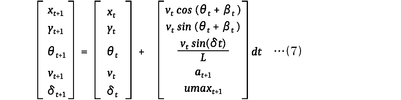
図1に示した目標状態候補生成部210は、周辺環境情報取得部110から取得した少なくとも1つ以上の走行可能状態、および自己状態取得部120から取得した移動体1の現在の状態に基づいて新たに決定した目標状態を目標状態候補として生成するものとして説明したが、図7に示すような構成とすることもできる。







図10は、料金所FSの手前の走行車線に、移動体1が進入しようとする状態を模式的に示しており、目標状態候補集合の周辺まで移動する際の中間地点において、局所目標状態LTSが算出された状態を示している。


局所目標状態生成部220は、目標状態候補生成部210で演算した各目標状態候補に対する所定の評価指標に基づいて重み付けを行い、重みに応じて局所目標状態を演算することができる。この処理の概念図を図15に示す。
局所目標状態生成部220は、図7に示した目標状態候補生成部210における仮想軌道生成部211で生成した仮想的な軌道の中でも、各目標状態候補に到達するまでの軌道に対して重み付けを行い、仮想的な軌道の重みを用いて、局所目標状態とすることもできる。この処理の概念図を図16に示す。


図22は、本開示に係る実施の形態2の通過地点生成装置を搭載した移動体1の構成を示すブロック図である。なお、図22においては、図1を用いて説明した移動体1と同一の構成については同一の符号を付し、重複する説明は省略する。
また、図22に示した目標状態候補生成部210の代わりに、図7に示した目標状態候補生成部210のように、仮想的な軌道を生成する仮想軌道生成部211と、仮想的な軌道について移動体1の動力学的な制約に基づいて評価する仮想軌道評価部212と、制約を破らない仮想的な軌道で到達できる走行可能状態を目標状態候補として選択する目標状態候補演算部213とを備えた構成とすることができる。
図26は、本開示に係る実施の形態3の通過地点生成装置が搭載された管制サーバー2(管制装置)と移動体1の構成を示すブロック図である。なお、図26においては、図1を用いて説明した移動体1と同一の構成については同一の符号を付し、重複する説明は省略する。
Claims (13)
- 移動体の到達すべき通過地点を生成する通過地点生成装置であって、
前記移動体の周辺環境情報と前記移動体の状態量に基づいて、少なくとも位置の状態量を含む複数の目標状態候補を演算する目標状態候補生成部と、
前記複数の目標状態候補の周辺までの中間地点において、いずれの目標状態候補においても到達可能な局所的な目標状態である局所目標状態を演算し、前記局所目標状態を前記通過地点として出力する局所目標状態生成部と、を備える、通過地点生成装置。 - 前記目標状態候補生成部は、
前記移動体が前記局所目標状態に到達した際に、前記いずれの目標状態候補においても到達可能なように、隣接する各目標状態が所定範囲内となるように互いに近い状態量の集合とする、請求項1記載の通過地点生成装置。 - 前記目標状態候補生成部は、
前記いずれの目標状態候補も、前記移動体の運動学的に到達可能な到達可能領域内にあるように演算する、請求項1または請求項2記載の通過地点生成装置。 - 前記目標状態候補生成部は、
前記いずれの目標状態候補も、前記移動体の乗り心地を考慮した移動により到達可能なように演算する、請求項1から請求項3の何れか1項に記載の通過地点生成装置。 - 前記複数の目標状態候補の各目標状態よりも大域的な目標状態を生成して大域的目標状態として出力する大域目標状態生成部をさらに備え、
前記目標状態候補生成部は、
前記いずれの目標状態候補も、前記大域的目標状態に到達可能なように演算する、請求項1から請求項4の何れか1項に記載の通過地点生成装置。 - 前記複数の目標状態候補のそれぞれは、
前記移動体が料金所ゲートを通過するための目標状態であって、
前記大域的目標状態は、
前記移動体が前記料金所ゲートを通過した後に、前記移動体が目指す位置の状態量を少なくとも含む、請求項5記載の通過地点生成装置。 - 前記目標状態候補生成部は、
複数の目標状態を通過する複数の仮想的な軌道を生成する仮想軌道生成部と、
前記複数の仮想的な軌道について前記移動体の動力学的な制約に基づいて評価する仮想軌道評価部と、
前記複数の仮想的な軌道のうち、前記制約を破らない仮想的な軌道で到達できる前記複数の目標状態を前記複数の目標状態候補として演算する目標状態候補演算部と、を有する、請求項1から請求項6の何れか1項に記載の通過地点生成装置。 - 前記局所目標状態生成部は、
前記複数の仮想的な軌道のうち、前記目標状態候補演算部で演算した前記複数の目標状態候補の中で最も中央に位置する目標状態候補まで到達する仮想的な軌道上の任意の位置を前記局所目標状態とする、請求項1から請求項7の何れか1項に記載の通過地点生成装置。 - 前記局所目標状態生成部は、
前記移動体が前記局所目標状態に到達する直前での前記局所目標状態の変更を制限する請求項1から請求項8の何れか1項に記載の通過地点生成装置。 - 前記局所目標状態生成部は、
前記複数の目標状態候補について、所定の評価指標に基づいて重み付けを行い、重みの値に基づいて前記局所目標状態を演算する、請求項1から請求項9の何れか1項に記載の通過地点生成装置。 - 前記目標状態候補生成部は、
前記複数の仮想的な軌道について、所定の評価指標に基づいて点数付けを行い、仮想的な軌道にそれぞれ付与された点数と閾値との比較を行い、前記閾値以上または前記閾値未満となる前記仮想的な軌道で走行する地点を前記複数の目標状態候補とする、請求項7または請求項8記載の通過地点生成装置。 - 前記局所目標状態生成部は、
前記複数の仮想的な軌道のうち、前記目標状態候補演算部で演算した前記複数の目標状態候補まで到達する仮想的な軌道に対して重み付けを行い、前記仮想的な軌道上の任意の位置と重みとを加重平均した状態を前記局所目標状態とする、請求項7または請求項8記載の通過地点生成装置。 - 前記通過地点生成装置は、
前記移動体との通信により前記移動体を管制制御する管制装置に搭載され、
前記局所目標状態生成部は、
管制制御の通信遅延を考慮して、前記いずれの目標状態候補にも到達可能なように前記局所目標状態を演算する、請求項1から請求項12の何れか1項に記載の通過地点生成装置。
Priority Applications (5)
| Application Number | Priority Date | Filing Date | Title |
|---|---|---|---|
| PCT/JP2022/019950 WO2023218560A1 (ja) | 2022-05-11 | 2022-05-11 | 通過地点生成装置 |
| US18/858,752 US20250269874A1 (en) | 2022-05-11 | 2022-05-11 | Passage point generation apparatus |
| CN202280095792.8A CN119156657A (zh) | 2022-05-11 | 2022-05-11 | 通过地点生成装置 |
| DE112022007188.5T DE112022007188T5 (de) | 2022-05-11 | 2022-05-11 | Passierungspunkt-Erzeugungsvorrichtung |
| JP2022557725A JP7275406B1 (ja) | 2022-05-11 | 2022-05-11 | 通過地点生成装置 |
Applications Claiming Priority (1)
| Application Number | Priority Date | Filing Date | Title |
|---|---|---|---|
| PCT/JP2022/019950 WO2023218560A1 (ja) | 2022-05-11 | 2022-05-11 | 通過地点生成装置 |
Publications (1)
| Publication Number | Publication Date |
|---|---|
| WO2023218560A1 true WO2023218560A1 (ja) | 2023-11-16 |
Family
ID=86332455
Family Applications (1)
| Application Number | Title | Priority Date | Filing Date |
|---|---|---|---|
| PCT/JP2022/019950 Ceased WO2023218560A1 (ja) | 2022-05-11 | 2022-05-11 | 通過地点生成装置 |
Country Status (5)
| Country | Link |
|---|---|
| US (1) | US20250269874A1 (ja) |
| JP (1) | JP7275406B1 (ja) |
| CN (1) | CN119156657A (ja) |
| DE (1) | DE112022007188T5 (ja) |
| WO (1) | WO2023218560A1 (ja) |
Families Citing this family (1)
| Publication number | Priority date | Publication date | Assignee | Title |
|---|---|---|---|---|
| JP2024037589A (ja) * | 2022-09-07 | 2024-03-19 | 株式会社Subaru | 車両の運転支援装置 |
Citations (4)
| Publication number | Priority date | Publication date | Assignee | Title |
|---|---|---|---|---|
| JP2019006205A (ja) * | 2017-06-22 | 2019-01-17 | 株式会社ショーワ | 経路生成装置、車両、及び車両システム |
| JP2019171938A (ja) * | 2018-03-27 | 2019-10-10 | トヨタ自動車株式会社 | 車両制御装置 |
| JP2019529209A (ja) * | 2017-01-10 | 2019-10-17 | 三菱電機株式会社 | 車両を駐車するシステム、方法及び非一時的コンピューター可読記憶媒体 |
| WO2021020297A1 (ja) * | 2019-07-26 | 2021-02-04 | 株式会社デンソー | 駐車支援装置 |
Family Cites Families (1)
| Publication number | Priority date | Publication date | Assignee | Title |
|---|---|---|---|---|
| WO2019199815A1 (en) * | 2018-04-10 | 2019-10-17 | Cavh Llc | Connected and automated vehicle systems and methods for the entire roadway network |
-
2022
- 2022-05-11 JP JP2022557725A patent/JP7275406B1/ja active Active
- 2022-05-11 WO PCT/JP2022/019950 patent/WO2023218560A1/ja not_active Ceased
- 2022-05-11 DE DE112022007188.5T patent/DE112022007188T5/de active Pending
- 2022-05-11 CN CN202280095792.8A patent/CN119156657A/zh active Pending
- 2022-05-11 US US18/858,752 patent/US20250269874A1/en active Pending
Patent Citations (4)
| Publication number | Priority date | Publication date | Assignee | Title |
|---|---|---|---|---|
| JP2019529209A (ja) * | 2017-01-10 | 2019-10-17 | 三菱電機株式会社 | 車両を駐車するシステム、方法及び非一時的コンピューター可読記憶媒体 |
| JP2019006205A (ja) * | 2017-06-22 | 2019-01-17 | 株式会社ショーワ | 経路生成装置、車両、及び車両システム |
| JP2019171938A (ja) * | 2018-03-27 | 2019-10-10 | トヨタ自動車株式会社 | 車両制御装置 |
| WO2021020297A1 (ja) * | 2019-07-26 | 2021-02-04 | 株式会社デンソー | 駐車支援装置 |
Also Published As
| Publication number | Publication date |
|---|---|
| US20250269874A1 (en) | 2025-08-28 |
| CN119156657A (zh) | 2024-12-17 |
| JPWO2023218560A1 (ja) | 2023-11-16 |
| JP7275406B1 (ja) | 2023-05-17 |
| DE112022007188T5 (de) | 2025-04-30 |
Similar Documents
| Publication | Publication Date | Title |
|---|---|---|
| US11698638B2 (en) | System and method for predictive path planning in autonomous vehicles | |
| US11126187B2 (en) | Systems and methods for controlling the operation of a vehicle | |
| US10953883B2 (en) | Vehicle control device | |
| US11465617B2 (en) | Vehicle path planning | |
| CN110126825B (zh) | 用于低级别前馈车辆控制策略的系统和方法 | |
| CN112292646B (zh) | 车辆的控制系统、用于控制车辆的方法和非暂时性计算机可读存储器 | |
| CN108693878B (zh) | 前进路线设定装置以及前进路线设定方法 | |
| CN106080598B (zh) | 实时预期速度控制 | |
| US10488863B2 (en) | Autonomous vehicle post-fault operation | |
| CN109990794A (zh) | 具有动态成本学习的自主驾驶轨迹规划器 | |
| JP7193656B2 (ja) | 割り込んでくる又は抜け出て行く車両を認識する制御ユニット及び方法 | |
| US12296845B2 (en) | Vehicle path adjustment with control barrier function | |
| CN117733835A (zh) | 动态边界框 | |
| CN120122640A (zh) | 一种露天矿环境下的无人驾驶车辆路径规划方法 | |
| CN114217601B (zh) | 自驾车的混合决策方法及其系统 | |
| WO2023218560A1 (ja) | 通過地点生成装置 | |
| KR20220088611A (ko) | 차량 및 자율 주행 시스템 | |
| JP7267383B1 (ja) | 車両制御装置及び車両制御方法 | |
| JP7614820B2 (ja) | 運転制御方法及び運転制御装置 | |
| CN117873052A (zh) | 具有实时函数逼近器的自动驾驶车辆的轨迹规划系统 | |
| US20250196886A1 (en) | Path planning and operation domain navigation with gnss error predictions | |
| CN119645031B (zh) | 一种无人车静态避障方法 | |
| JP7241800B2 (ja) | 車両制御装置及び車両制御方法 | |
| JP7710630B1 (ja) | 軌道生成装置、および、軌道生成方法 | |
| EP4561884B1 (en) | Control system and method for controlling autonomous driving of a vehicle |
Legal Events
| Date | Code | Title | Description |
|---|---|---|---|
| ENP | Entry into the national phase |
Ref document number: 2022557725 Country of ref document: JP Kind code of ref document: A |
|
| 121 | Ep: the epo has been informed by wipo that ep was designated in this application |
Ref document number: 22941640 Country of ref document: EP Kind code of ref document: A1 |
|
| WWE | Wipo information: entry into national phase |
Ref document number: 18858752 Country of ref document: US |
|
| WWE | Wipo information: entry into national phase |
Ref document number: 202280095792.8 Country of ref document: CN |
|
| WWE | Wipo information: entry into national phase |
Ref document number: 112022007188 Country of ref document: DE |
|
| WWP | Wipo information: published in national office |
Ref document number: 112022007188 Country of ref document: DE |
|
| 122 | Ep: pct application non-entry in european phase |
Ref document number: 22941640 Country of ref document: EP Kind code of ref document: A1 |
|
| WWP | Wipo information: published in national office |
Ref document number: 18858752 Country of ref document: US |