WO2023218557A1 - 動作分析装置、動作分析方法、動作分析プログラムおよび動作分析システム - Google Patents
動作分析装置、動作分析方法、動作分析プログラムおよび動作分析システム Download PDFInfo
- Publication number
- WO2023218557A1 WO2023218557A1 PCT/JP2022/019932 JP2022019932W WO2023218557A1 WO 2023218557 A1 WO2023218557 A1 WO 2023218557A1 JP 2022019932 W JP2022019932 W JP 2022019932W WO 2023218557 A1 WO2023218557 A1 WO 2023218557A1
- Authority
- WO
- WIPO (PCT)
- Prior art keywords
- target
- time
- timing
- motion
- information
- Prior art date
- Legal status (The legal status is an assumption and is not a legal conclusion. Google has not performed a legal analysis and makes no representation as to the accuracy of the status listed.)
- Ceased
Links
Images





Classifications
-
- G—PHYSICS
- G06—COMPUTING OR CALCULATING; COUNTING
- G06T—IMAGE DATA PROCESSING OR GENERATION, IN GENERAL
- G06T7/00—Image analysis
- G06T7/20—Analysis of motion
-
- G—PHYSICS
- G06—COMPUTING OR CALCULATING; COUNTING
- G06V—IMAGE OR VIDEO RECOGNITION OR UNDERSTANDING
- G06V20/00—Scenes; Scene-specific elements
- G06V20/70—Labelling scene content, e.g. deriving syntactic or semantic representations
Definitions
- the present disclosure relates to technology for analyzing human motion.
- Patent Document 1 proposes a method of automating analysis.
- a time series of posture information obtained using a camera is defined as a motion trajectory, and the motion trajectory is compared with a previously learned trajectory to identify the work content.
- Obtaining posture information using a camera reduces the burden on workers.
- An object of the present disclosure is to enable correct recognition of the analysis target work even when setup work occurs between cycles of the analysis target work.
- the motion analysis device of the present disclosure includes: a video reception unit that receives a video including frames at each shooting time obtained by photographing a subject performing a plurality of target actions with a set-up action in between; a skeletal extraction unit that extracts skeletal information of the subject reflected in the frame at each shooting time as target skeletal information; a timing detection unit that detects at least one of a start timing and an end timing for each target operation; Based on at least one of the start timing of each target operation and the end timing of each target operation, for each target time at which each target operation is performed, including the target time and excluding the time at which the setup operation was performed.
- a trajectory extraction unit that extracts two or more pieces of target skeleton information in a target time period as trajectory information; For each target time, the two or more pieces of target skeleton information of the trajectory information are extracted from reference skeleton data indicating a time series of reference skeleton information of each target motion and a motion label of each time in the time series.
- a matching unit that finds two or more matching pieces of reference skeleton information and obtains the movement label at a reference time in a time zone corresponding to the found two or more pieces of reference skeleton information as the movement label of the target movement; , is provided.
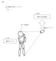
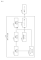
- FIG. 1 is a configuration diagram of a motion analysis system 100 in Embodiment 1.
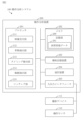
- FIG. FIG. 2 is a configuration diagram of a motion analysis device 200 in the first embodiment.
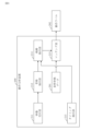
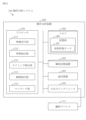
- FIG. 2 is a functional configuration diagram of motion analysis device 200 in Embodiment 1.
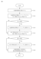
- 1 is a flowchart of a motion analysis method in Embodiment 1.
- 5 is a flowchart of step S140 in the first embodiment.
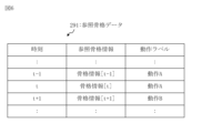
- FIG. 3 is a diagram showing an example of reference skeleton data 291 in the first embodiment.
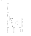
- FIG. 3 is a diagram showing recognition accuracy in conventional technology.
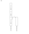
- FIG. 3 is a diagram showing recognition accuracy in Embodiment 1.
- FIG. 7 is a flowchart of a motion analysis method in Embodiment 2. Flowchart of step S240 in Embodiment 2.
- FIG. 7 is a diagram showing recognition accuracy in Embodiment 2.
- FIG. 3 is a configuration diagram of a motion analysis system 100 in Embodiment 3.
- FIG. 3 is a functional configuration diagram of a motion analysis device 200 in Embodiment 3.
- 7 is a flowchart of a motion analysis method in Embodiment 3.
- FIG. 2 is a hardware configuration diagram of a motion analysis device 200 in an embodiment.
- the motion analysis system 100 will be explained based on FIGS. 1 to 8.
- the motion analysis system 100 is a system for analyzing the motion of a subject 101.
- the subject 101 is a person who is the subject of analysis.
- the motion analysis system 100 includes a photographing device 111, an operation sensor 112, and a motion analysis device 200.
- the photographing device 111 is a device that photographs the subject 101. Specific examples of the photographing device 111 are a camera and a three-dimensional sensor.
- the operation sensor 112 is a sensor that detects an operation performed by the subject 101. Specific examples of the operation sensor 112 are a button device, a barcode reader, and a PLC.
- a button device detects a button press.
- a barcode reader detects reading of a barcode.
- the PLC detects the switching of a motorized tool.
- PLC is an abbreviation for programmable logic controller.
- the configuration of the motion analysis device 200 will be explained based on FIG. 2.
- the motion analysis device 200 is a computer that includes hardware such as a processor 201, a memory 202, an auxiliary storage device 203, a communication device 204, and an input/output interface 205. These pieces of hardware are connected to each other via signal lines.
- the processor 201 is an IC that performs arithmetic processing and controls other hardware.
- processor 201 is a CPU.
- IC is an abbreviation for Integrated Circuit.
- CPU is an abbreviation for Central Processing Unit.
- Memory 202 is a volatile or non-volatile storage device. Memory 202 is also called main storage or main memory. For example, memory 202 is a RAM. The data stored in memory 202 is stored in auxiliary storage device 203 as needed. RAM is an abbreviation for Random Access Memory.
- the auxiliary storage device 203 is a nonvolatile storage device.
- the auxiliary storage device 203 is a ROM, an HDD, a flash memory, or a combination thereof. Data stored in auxiliary storage device 203 is loaded into memory 202 as needed.
- ROM is an abbreviation for Read Only Memory.
- HDD is an abbreviation for Hard Disk Drive.
- Communication device 204 is a receiver and transmitter.
- communication device 204 is a communication chip or NIC.
- Communication between the motion analysis device 200 is performed using a communication device 204.
- NIC is an abbreviation for Network Interface Card.
- the input/output interface 205 is a port to which an input device and an output device are connected.
- the input/output interface 205 is a USB terminal
- the input device is a keyboard and a mouse
- the output device is a display.
- Input/output of the motion analysis device 200 is performed using an input/output interface 205.
- USB is an abbreviation for Universal Serial Bus.
- the photographing device 111 and the operation sensor 112 are connected to the input/output interface 205. However, the photographing device 111 and the operation sensor 112 may be connected to the communication device 204.
- the motion analysis device 200 includes elements such as a video reception section 211, a skeleton extraction section 212, a timing detection section 213, a trajectory extraction section 214, and a matching section 215. These elements are implemented in software.
- the auxiliary storage device 203 stores a motion analysis program for causing the computer to function as a video reception section 211, a skeleton extraction section 212, a timing detection section 213, a trajectory extraction section 214, and a matching section 215.
- the motion analysis program is loaded into memory 202 and executed by processor 201.
- the auxiliary storage device 203 further stores an OS. At least a portion of the OS is loaded into memory 202 and executed by processor 201.
- Processor 201 executes a motion analysis program while executing the OS.
- OS is an abbreviation for Operating System.
- Input/output data of the motion analysis program is stored in the storage unit 290.
- reference skeleton data 291 is stored in the storage unit 290 in advance.
- the reference skeleton data 291 will be described later.
- Memory 202 functions as storage section 290.
- storage devices such as the auxiliary storage device 203, a register in the processor 201, and a cache memory in the processor 201 may function as the storage unit 290 instead of the memory 202 or together with the memory 202.
- the motion analysis device 200 may include a plurality of processors that replace the processor 201.
- the motion analysis program can be recorded (stored) in a computer-readable manner on a non-volatile recording medium such as an optical disk or a flash memory.
- FIG. 3 shows the relationship between the elements of the motion analysis device 200.
- the motion analysis device 200 analyzes the motion of the subject 101 and outputs a motion label 292.
- the motion label 292 identifies the motion of the subject 101.
- the operation procedure of the motion analysis system 100 corresponds to a motion analysis method. Further, the operation procedure of the motion analysis device 200 corresponds to the processing procedure by the motion analysis program.
- the subject 101 performs a plurality of target operations with a setup operation in between.
- a specific example of the target person 101 is a worker.
- a specific example of the target action is a work performed by a worker.
- the plurality of target operations are the same type of work, and the same type of work is performed multiple times.
- a setup operation is an operation performed between target operations.
- a setup operation is preparation for work.
- the subject 101 For each target motion, the subject 101 performs a start operation at the start of the target motion, and performs an end operation at the end of the target motion.
- the start operation and the end operation are device operations.
- the device to be operated is called an operating device.
- the operating device is placed at the location where the target action is performed.
- the operating device is a button device, a barcode reader, or a power tool.
- Power tools are electrically powered tools used for target operations.
- the power tool is an electric screwdriver.
- the start and end operations are pressing a button, reading a barcode, or flipping a switch on a power tool.
- step S110 the photographing device 111 photographs the subject 101 and outputs the video.
- the output video is input to the motion analysis device 200.
- the video reception unit 211 receives the input video.
- the video is data obtained by shooting, and includes frames at each shooting time.
- a frame is data corresponding to an image.
- the skeleton extraction unit 212 extracts the skeleton information of the subject 101 shown in the frame for each shooting time.
- the extraction method is a conventional technique, and skeletal information is obtained by image analysis of frames.
- the skeleton information indicates the skeleton of the subject 101.
- the skeletal information indicates the position of each joint of the subject 101.
- the posture of the subject 101 is specified by the skeletal information.
- the extracted skeleton information is referred to as target skeleton information.
- step S130 the timing detection unit 213 detects at least one of the start timing and end timing for each target operation.
- the start timing and end timing are detected as follows.
- the operation sensor 112 detects the performed operation and outputs a detection signal every time a start operation or an end operation is performed.
- the detection signal differs depending on the type of operation.
- the output detection signal is input to the motion analysis device 200.
- the timing detection unit 213 receives each detection signal, and detects the timing at which each detection signal is received as a start timing or an end timing. That is, the timing detection unit 213 detects the timing at which the start operation is detected as the start timing. Furthermore, the timing detection unit 213 detects the timing at which the end operation is detected as the end timing.
- the trajectory extraction unit 214 extracts trajectory information for each target time based on at least one of the start timing and end timing of each target motion.
- the target time is each time in a time period (operation time period) in which each target action is performed.
- the operation time period of each target operation is the time period from the start timing to the end timing.
- Each operating time period is calculated by the locus extraction unit 214.
- the trajectory information is two or more pieces of target skeleton information in a time period (target time period) that includes the target time and does not include the setup time.
- the target time period is part of the operating time period.
- Step S140 will be explained based on FIG. 5. Steps S141 to S146 are executed at each target time.
- the trajectory extraction unit 214 calculates a target time period. Specifically, the trajectory extraction unit 214 calculates a time period that includes the target time and has a reference time length. The calculated time period is the target time period. The reference time length is a predetermined time length. Assume that the target time is t and the reference time length is 3t. For example, the target time period to be calculated is the time period from time (t-1) to time (t+1).
- the target time period is adjusted through steps S142 to S145.
- step S142 the trajectory extraction unit 214 determines whether the beginning time of the target time period is earlier than the start timing of the target operation at the target time. If the start time of the target time zone is earlier than the start timing of the target operation at the target time, the process advances to step S143. If the start time of the target time zone is not earlier than the start timing of the target operation at the target time, the process proceeds to step S144.
- step S143 the trajectory extraction unit 214 changes the start time of the target time period to the start timing of the target operation at the target time. This shortens the target time period.
- step S144 the trajectory extraction unit 214 determines whether the final time of the target time period is later than the end timing of the target operation at the target time. If the end time of the target time period is later than the end timing of the target operation at the target time, the process proceeds to step S145. If the end time of the target time zone is not later than the end timing of the target operation at the target time, the process proceeds to step S146.
- step S145 the trajectory extraction unit 214 changes the end time of the target time period to the end timing of the target operation at the target time. This shortens the target time period.
- the target time period is determined through steps S141 to S145.
- step S146 the trajectory extraction unit 214 extracts target skeleton information at each time in the target time period from the target skeleton information obtained in step S120. As a result, two or more pieces of target skeleton information are extracted. Two or more pieces of extracted target skeleton information constitute trajectory information.
- step S150 the matching unit 215 acquires the motion label of the target motion from the reference skeleton data 291 for each target time.
- the reference skeleton data 291 will be explained based on FIG. 6.
- the reference skeleton data 291 indicates a time series of reference skeleton information and a motion label at each time in the time series.
- the time series of reference skeleton information is a time series of skeleton information for each target motion.
- the time series of skeleton information in the setup operation is not included in the reference skeleton data 291.
- the target motion includes the motion after the start operation and the motion at the time of the end operation.
- the time series of reference skeleton information is extracted from a video obtained by photographing an operator performing a target action.
- the method for extracting reference skeleton information is the same as the method for extracting target skeleton information.
- the operator may perform the target motion two or more times, and the average of the extracted time series of the two times may be set as the reference skeleton data 291.
- the reference skeleton data 291 may be a trained model obtained by learning a plurality of videos.
- step S150 will be specifically explained.
- the following processing is performed for each target time.
- the trajectory information at the target time is referred to as target trajectory information.
- the matching unit 215 searches the reference skeleton data 291.
- the search for the reference skeleton data 291 is performed, for example, by the method disclosed in Patent Document 1.
- the matching unit 215 finds reference trajectory information that matches the target trajectory information from the reference skeleton data 291.
- the reference trajectory information is two or more pieces of reference skeleton information.
- the time period corresponding to the reference trajectory information is referred to as a reference time period.
- the time length of the reference time slot is the same as the time length of the target time slot.
- the matching unit 215 selects a reference time from the reference time zone corresponding to the found reference trajectory information, and acquires the motion label of the selected reference time from the reference skeleton data 291.
- the acquired motion label becomes the motion label of the target motion.
- the position of the reference time in the reference time zone is the same as the position of the target time in the target time zone.
- step S150 A specific example of step S150 will be described based on FIG. 6. It is assumed that the target time period is three consecutive times, and the target trajectory information is three target skeleton information of the target time period. In this case, the reference time period is three consecutive times, and the reference trajectory information is three pieces of reference skeleton information in the reference time period. Then, the matching unit 215 compares the target trajectory information with the reference trajectory information for each reference trajectory information whose reference time is each time. Assume that the target time in the target time zone is the second time. In this case, the reference time of the reference time zone is the second time in the reference time zone. Further, it is assumed that the reference trajectory information that matches the target trajectory information is skeleton information [t-1], skeleton information [t], and skeleton information [t+1]. In this case, the standard time of the reference time zone is time t. Then, the matching unit 215 obtains the motion label "motion A" at time t.
- the matching unit 215 outputs a motion label of the target motion for each target time. Specific examples of output are display on a display and storage on a storage medium.
- FIG. 7 shows recognition accuracy in the prior art.
- the time length of the trajectory information is changed depending on the break between the analysis target work and the setup work. In other words, the trajectory extraction range and the matching range are changed and matching is performed.
- trajectory extraction range and the matching range are changed based on the start timing of the cycle of the analysis target work and the end timing of the cycle of the analysis target work. Therefore, recognition accuracy does not decrease even at times close to the setup work time period.
- matching of trajectory information can be performed without including skeleton information during setup work. This prevents cases in which the analysis target work is not recognized or cases in which the analysis target work is erroneously recognized.
- Embodiment 2 With regard to a mode in which the target time period is changed according to a specific timing during the target operation, the main differences from the first embodiment will be explained based on FIGS. 9 to 11.
- the target person 101 performs a specific operation at a specific timing during the target action.
- the specific operation is a device operation.
- the specific operation is pressing a button, reading a barcode, or switching a switch on an operating tool.
- step S210 the video reception unit 211 receives the video.
- Step S210 is the same as step S110 in the first embodiment.
- step S220 the skeleton extraction unit 212 extracts elephant skeleton information for each photographing time.
- Step S220 is the same as step S120 in the first embodiment.
- step S230 the timing detection unit 213 detects at least one of a start timing and an end timing for each target operation. Further, the timing detection unit 213 detects specific timing during the target operation.
- the specific timing detection method is the same as the start timing and end timing detection methods. That is, the timing detection unit 213 detects the timing at which the specific operation is detected as the specific timing.
- step S240 the trajectory extraction unit 214 extracts trajectory information for each target time based on the specific timing and at least one of the start timing of each target motion and the end timing of each target motion.
- Step S240 will be explained based on FIG. 10. Steps S241 to S246 are executed at each target time.
- step S241 the trajectory extraction unit 214 calculates a target time period.
- Step S241 is the same as step S141 in the first embodiment.
- step S242 the trajectory extraction unit 214 determines whether the beginning time of the target time period is earlier than the start timing of the target motion at the target time or the specific timing in the middle of the target motion. If the beginning time of the target time period is earlier than the start timing of the target action at the target time or the specific timing in the middle of the target action, the process proceeds to step S243. If the start time of the target time zone is not earlier than the start timing of the target action and the specific timing in the middle of the target action at the target time, the process proceeds to step S244.
- step S243 the trajectory extraction unit 214 changes the beginning time of the target time period to the start timing of the target action at the target time or a specific timing in the middle of the target action. If the start time of the target time slot is earlier than the start timing of the target operation at the target time, the start time of the target time slot is changed to the start timing. If the start time of the target time slot is earlier than the specific timing in the middle of the target operation, the start time of the target time slot is changed to the specific timing.
- step S244 the trajectory extracting unit 214 determines whether the final time of the target time period is later than the end timing of the target motion at the target time or the specific timing in the middle of the target motion. If the end time of the target time period is later than the end timing of the target action at the target time or the specific timing in the middle of the target action, the process proceeds to step S245. If the end time of the target time zone is not later than the end timing of the target motion at the target time and the specific timing in the middle of the target motion, the process proceeds to step S246.
- step S245 the trajectory extraction unit 214 changes the final time of the target time period to the end timing of the target motion at the target time or a specific timing in the middle of the target motion. If the final time of the target time slot is later than the end timing of the target operation at the target time, the final time of the target time slot is changed to the end timing. If the final time of the target time slot is later than the specific timing in the middle of the target operation, the final time of the target time slot is changed to the specific timing.
- step S246 the trajectory extraction unit 214 extracts target skeleton information at each time in the target time period.
- Step S246 is the same as step S146 in the first embodiment.
- FIG. 11 shows recognition accuracy in the second embodiment.
- the trajectory extraction range and matching range are changed according to specific timing during the target motion. This improves recognition accuracy at times before and after the specific timing.
- Embodiment 3 With regard to the embodiment in which various timings are detected without using the operation sensor 112, the main differences from the second embodiment will be explained based on FIGS. 12 to 14.
- the configuration of the motion analysis system 100 will be explained based on FIG. 12.
- the motion analysis system 100 may not include the operation sensor 112.
- FIG. 13 shows the relationship between the elements of the motion analysis device 200.
- the timing detection section 213 uses the video received by the video reception section 211.
- Step S330 Step S210, step S220, step S240, and step S250 are as described in the second embodiment.
- step S330 the timing detection unit 213 searches the video for a frame in which a feature that appears at least at one of the start timing and end timing is captured. If a frame is found that shows a feature that appears at the start timing, the timing detection unit 213 detects the photographing time of the found frame as the start timing. If a frame is found that shows a feature that appears at the end timing, the timing detection unit 213 detects the photographing time of the found frame as the end timing. Further, the timing detection unit 213 searches the video for a frame that shows a feature that appears at a specific timing, and detects the photographing time of the found frame as the specific timing.
- features that appear within a frame at each timing are defined in advance. For example, the features that appear within the frame represent what happens when a product is placed in the designated area or what happens when a hand passes through the designated area.
- the motion analysis device 200 includes a processing circuit 209.
- the processing circuit 209 is hardware that implements the video reception section 211, the skeleton extraction section 212, the timing detection section 213, the trajectory extraction section 214, and the matching section 215.
- the processing circuit 209 may be dedicated hardware or may be the processor 201 that executes a program stored in the memory 202.
- processing circuit 209 is dedicated hardware, processing circuit 209 is, for example, a single circuit, a composite circuit, a programmed processor, a parallel programmed processor, an ASIC, an FPGA, or a combination thereof.
- ASIC is an abbreviation for Application Specific Integrated Circuit.
- FPGA is an abbreviation for Field Programmable Gate Array.
- the motion analysis device 200 may include a plurality of processing circuits that replace the processing circuit 209.
- processing circuit 209 some functions may be realized by dedicated hardware, and the remaining functions may be realized by software or firmware.
- the functions of the motion analysis device 200 can be realized by hardware, software, firmware, or a combination thereof.
- the "unit" of each element of the motion analysis device 200 may be read as “process”, “process”, “circuit”, or “circuitry”.
- 100 motion analysis system 101 subject, 111 photographing device, 112 operation sensor, 200 motion analysis device, 201 processor, 202 memory, 203 auxiliary storage device, 204 communication device, 205 input/output interface, 209 processing circuit, 211 video reception unit , 212 Skeleton extraction unit, 213 Timing detection unit, 214 Trajectory extraction unit, 215 Matching unit, 290 Storage unit, 291 Reference skeleton data, 292 Motion label.
Landscapes
- Engineering & Computer Science (AREA)
- Physics & Mathematics (AREA)
- General Physics & Mathematics (AREA)
- Multimedia (AREA)
- Theoretical Computer Science (AREA)
- Computational Linguistics (AREA)
- Computer Vision & Pattern Recognition (AREA)
- Image Analysis (AREA)
Abstract
動作分析装置(200)は、対象者(101)を撮影することによって得られる映像を受け付け、各フレームに映った前記対象者の対象骨格情報を抽出し、対象動作ごとに開始タイミングと終了タイミングを検出し、各開始タイミングと各終了タイミングに基づいて対象時刻ごとに前記対象時刻を含み段取り動作の時刻を含まない対象時間帯の2つ以上の前記対象骨格情報を軌跡情報として抽出し、前記対象時刻ごとに参照骨格データから前記軌跡情報の前記2つ以上の前記対象骨格情報と合致する2つ以上の参照骨格情報を見つけ、見つかった前記2つ以上の前記参照骨格情報に対応する時間帯の基準時刻の動作ラベルを取得する。
Description
本開示は、人の動作を分析する技術に関するものである。
産業分野において、作業者のサイクルタイムの計測と作業内容の分析が人手で行われている。しかし、人手での分析は負荷が大きい。
特許文献1は、分析を自動化する手法を提案している。
この手法では、カメラを使って得られた姿勢情報の時系列が動作軌跡として定義され、動作軌跡があらかじめ学習された軌跡と比較され、作業内容が特定される。
姿勢情報がカメラを使って得られることで、作業者に負担がかからない。
この手法では、カメラを使って得られた姿勢情報の時系列が動作軌跡として定義され、動作軌跡があらかじめ学習された軌跡と比較され、作業内容が特定される。
姿勢情報がカメラを使って得られることで、作業者に負担がかからない。
特許文献1の手法により、工場のラインの作業者について作業時間及び作業手順を分析することができる。分析対象時刻を含む前後の骨格の軌跡が登録された軌跡と比較され、作業時間及び作業手順が検出される。
しかし、実際の作業では、分析対象作業のサイクル間に段取り作業が発生することがある。この場合、段取り作業の発生時の軌跡は登録された軌跡と異なるため、分析対象作業が認識されない可能性がある。または、分析対象作業が誤認識される可能性がある。
しかし、実際の作業では、分析対象作業のサイクル間に段取り作業が発生することがある。この場合、段取り作業の発生時の軌跡は登録された軌跡と異なるため、分析対象作業が認識されない可能性がある。または、分析対象作業が誤認識される可能性がある。
本開示は、分析対象作業のサイクル間に段取り作業が発生した場合であっても分析対象作業を正しく認識できるようにすることを目的とする。
本開示の動作分析装置は、
段取り動作を挟んで複数の対象動作を行う対象者を撮影することによって得られ各撮影時刻のフレームを含む映像を受け付ける映像受付部と、
前記撮影時刻ごとに前記フレームに映った前記対象者の骨格情報を対象骨格情報として抽出する骨格抽出部と、
前記対象動作ごとに開始タイミングと終了タイミングの少なくとも一方を検出するタイミング検出部と、
各対象動作の前記開始タイミングと各対象動作の前記終了タイミングの少なくとも一方に基づいて、各対象動作が行われた対象時刻ごとに、前記対象時刻を含み前記段取り動作が行われた時刻を含まない対象時間帯の2つ以上の前記対象骨格情報を軌跡情報として抽出する軌跡抽出部と、
前記対象時刻ごとに、各対象動作の参照骨格情報の時系列と、前記時系列の各時刻の動作ラベルと、を示す参照骨格データから、前記軌跡情報の前記2つ以上の前記対象骨格情報と合致する2つ以上の前記参照骨格情報を見つけ、見つかった前記2つ以上の前記参照骨格情報に対応する時間帯の基準時刻の前記動作ラベルを前記対象動作の前記動作ラベルとして取得するマッチング部と、を備える。
段取り動作を挟んで複数の対象動作を行う対象者を撮影することによって得られ各撮影時刻のフレームを含む映像を受け付ける映像受付部と、
前記撮影時刻ごとに前記フレームに映った前記対象者の骨格情報を対象骨格情報として抽出する骨格抽出部と、
前記対象動作ごとに開始タイミングと終了タイミングの少なくとも一方を検出するタイミング検出部と、
各対象動作の前記開始タイミングと各対象動作の前記終了タイミングの少なくとも一方に基づいて、各対象動作が行われた対象時刻ごとに、前記対象時刻を含み前記段取り動作が行われた時刻を含まない対象時間帯の2つ以上の前記対象骨格情報を軌跡情報として抽出する軌跡抽出部と、
前記対象時刻ごとに、各対象動作の参照骨格情報の時系列と、前記時系列の各時刻の動作ラベルと、を示す参照骨格データから、前記軌跡情報の前記2つ以上の前記対象骨格情報と合致する2つ以上の前記参照骨格情報を見つけ、見つかった前記2つ以上の前記参照骨格情報に対応する時間帯の基準時刻の前記動作ラベルを前記対象動作の前記動作ラベルとして取得するマッチング部と、を備える。
本開示によれば、分析対象作業のサイクル間に段取り作業が発生した場合であっても分析対象作業を正しく認識することが可能となる。
実施の形態および図面において、同じ要素または対応する要素には同じ符号を付している。説明した要素と同じ符号が付された要素の説明は適宜に省略または簡略化する。図中の矢印はデータの流れ又は処理の流れを主に示している。
実施の形態1.
動作分析システム100について、図1から図8に基づいて説明する。
動作分析システム100は、対象者101の動作を分析するためのシステムである。
対象者101は、分析の対象となる人である。
動作分析システム100について、図1から図8に基づいて説明する。
動作分析システム100は、対象者101の動作を分析するためのシステムである。
対象者101は、分析の対象となる人である。
***構成の説明***
図1に基づいて、動作分析システム100の構成を説明する。
動作分析システム100は、撮影デバイス111と、操作センサ112と、動作分析装置200と、を備える。
撮影デバイス111は、対象者101を撮影するデバイスである。撮影デバイス111の具体例は、カメラおよび三次元センサである。
操作センサ112は、対象者101によって行われる操作を検出するセンサである。操作センサ112の具体例は、ボタンデバイス、バーコードリーダおよびPLCである。ボタンデバイスは、ボタンの押下を検出する。バーコードリーダは、バーコードの読み取りを検出する。PLCは、電動式の道具のスイッチの切り替えを検出する。PLCはプログラマブルロジックコントローラの略称である。
図1に基づいて、動作分析システム100の構成を説明する。
動作分析システム100は、撮影デバイス111と、操作センサ112と、動作分析装置200と、を備える。
撮影デバイス111は、対象者101を撮影するデバイスである。撮影デバイス111の具体例は、カメラおよび三次元センサである。
操作センサ112は、対象者101によって行われる操作を検出するセンサである。操作センサ112の具体例は、ボタンデバイス、バーコードリーダおよびPLCである。ボタンデバイスは、ボタンの押下を検出する。バーコードリーダは、バーコードの読み取りを検出する。PLCは、電動式の道具のスイッチの切り替えを検出する。PLCはプログラマブルロジックコントローラの略称である。
図2に基づいて、動作分析装置200の構成を説明する。
動作分析装置200は、プロセッサ201とメモリ202と補助記憶装置203と通信装置204と入出力インタフェース205といったハードウェアを備えるコンピュータである。これらのハードウェアは、信号線を介して互いに接続されている。
動作分析装置200は、プロセッサ201とメモリ202と補助記憶装置203と通信装置204と入出力インタフェース205といったハードウェアを備えるコンピュータである。これらのハードウェアは、信号線を介して互いに接続されている。
プロセッサ201は、演算処理を行うICであり、他のハードウェアを制御する。例えば、プロセッサ201はCPUである。
ICは、Integrated Circuitの略称である。
CPUは、Central Processing Unitの略称である。
ICは、Integrated Circuitの略称である。
CPUは、Central Processing Unitの略称である。
メモリ202は揮発性または不揮発性の記憶装置である。メモリ202は、主記憶装置またはメインメモリとも呼ばれる。例えば、メモリ202はRAMである。メモリ202に記憶されたデータは必要に応じて補助記憶装置203に保存される。
RAMは、Random Access Memoryの略称である。
RAMは、Random Access Memoryの略称である。
補助記憶装置203は不揮発性の記憶装置である。例えば、補助記憶装置203は、ROM、HDD、フラッシュメモリまたはこれらの組み合わせである。補助記憶装置203に記憶されたデータは必要に応じてメモリ202にロードされる。
ROMは、Read Only Memoryの略称である。
HDDは、Hard Disk Driveの略称である。
ROMは、Read Only Memoryの略称である。
HDDは、Hard Disk Driveの略称である。
通信装置204はレシーバ及びトランスミッタである。例えば、通信装置204は通信チップまたはNICである。動作分析装置200の通信は通信装置204を用いて行われる。
NICは、Network Interface Cardの略称である。
NICは、Network Interface Cardの略称である。
入出力インタフェース205は、入力装置および出力装置が接続されるポートである。例えば、入出力インタフェース205はUSB端子であり、入力装置はキーボードおよびマウスであり、出力装置はディスプレイである。動作分析装置200の入出力は入出力インタフェース205を用いて行われる。
USBは、Universal Serial Busの略称である。
USBは、Universal Serial Busの略称である。
撮影デバイス111および操作センサ112は、入出力インタフェース205に接続される。但し、撮影デバイス111および操作センサ112は、通信装置204に接続されてもよい。
動作分析装置200は、映像受付部211と骨格抽出部212とタイミング検出部213と軌跡抽出部214とマッチング部215といった要素を備える。これらの要素はソフトウェアで実現される。
補助記憶装置203には、映像受付部211と骨格抽出部212とタイミング検出部213と軌跡抽出部214とマッチング部215としてコンピュータを機能させるための動作分析プログラムが記憶されている。動作分析プログラムは、メモリ202にロードされて、プロセッサ201によって実行される。
補助記憶装置203には、さらに、OSが記憶されている。OSの少なくとも一部は、メモリ202にロードされて、プロセッサ201によって実行される。
プロセッサ201は、OSを実行しながら、動作分析プログラムを実行する。
OSは、Operating Systemの略称である。
補助記憶装置203には、さらに、OSが記憶されている。OSの少なくとも一部は、メモリ202にロードされて、プロセッサ201によって実行される。
プロセッサ201は、OSを実行しながら、動作分析プログラムを実行する。
OSは、Operating Systemの略称である。
動作分析プログラムの入出力データは記憶部290に記憶される。例えば、記憶部290には、参照骨格データ291が予め記憶される。参照骨格データ291について後述する。
メモリ202は記憶部290として機能する。但し、補助記憶装置203、プロセッサ201内のレジスタおよびプロセッサ201内のキャッシュメモリなどの記憶装置が、メモリ202の代わりに、又は、メモリ202と共に、記憶部290として機能してもよい。
メモリ202は記憶部290として機能する。但し、補助記憶装置203、プロセッサ201内のレジスタおよびプロセッサ201内のキャッシュメモリなどの記憶装置が、メモリ202の代わりに、又は、メモリ202と共に、記憶部290として機能してもよい。
動作分析装置200は、プロセッサ201を代替する複数のプロセッサを備えてもよい。
動作分析プログラムは、光ディスクまたはフラッシュメモリ等の不揮発性の記録媒体にコンピュータ読み取り可能に記録(格納)することができる。
図3に、動作分析装置200の要素同士の関係を示す。
動作分析装置200は、対象者101の動作を分析し、動作ラベル292を出力する。
動作ラベル292は、対象者101の動作を識別する。
動作分析装置200は、対象者101の動作を分析し、動作ラベル292を出力する。
動作ラベル292は、対象者101の動作を識別する。
***動作の説明***
動作分析システム100の動作の手順は動作分析方法に相当する。また、動作分析装置200の動作の手順は動作分析プログラムによる処理の手順に相当する。
動作分析システム100の動作の手順は動作分析方法に相当する。また、動作分析装置200の動作の手順は動作分析プログラムによる処理の手順に相当する。
動作分析方法の前提を説明する。
対象者101は、段取り動作を挟んで複数の対象動作を行う。
対象者101の具体例は、作業者である。
対象動作の具体例は、作業者によって行われる作業である。例えば、複数の対象動作は同じ種類の作業であり、同じ種類の作業が複数回行われる。
段取り動作は、対象動作の間に行われる動作である。例えば、段取り動作は、作業のための準備である。
対象者101は、段取り動作を挟んで複数の対象動作を行う。
対象者101の具体例は、作業者である。
対象動作の具体例は、作業者によって行われる作業である。例えば、複数の対象動作は同じ種類の作業であり、同じ種類の作業が複数回行われる。
段取り動作は、対象動作の間に行われる動作である。例えば、段取り動作は、作業のための準備である。
対象者101は、対象動作ごとに、対象動作の開始時に開始操作を行い、対象動作の終了時に終了操作を行う。
具体的には、開始操作および終了操作はデバイスの操作である。操作されるデバイスを操作デバイスと称する。操作デバイスは、対象動作が行われる場所に配置される。
例えば、操作デバイスは、ボタンデバイス、バーコードリーダまたは電動道具である。電動道具は、対象動作のために使用される電動式の道具である。例えば、電動道具は電動ドライバである。
例えば、開始操作および終了操作は、ボタンの押下、バーコードの読み取り、または、電動道具のスイッチの切り替えである。
具体的には、開始操作および終了操作はデバイスの操作である。操作されるデバイスを操作デバイスと称する。操作デバイスは、対象動作が行われる場所に配置される。
例えば、操作デバイスは、ボタンデバイス、バーコードリーダまたは電動道具である。電動道具は、対象動作のために使用される電動式の道具である。例えば、電動道具は電動ドライバである。
例えば、開始操作および終了操作は、ボタンの押下、バーコードの読み取り、または、電動道具のスイッチの切り替えである。
図4に基づいて、動作分析方法を説明する。
ステップS110において、撮影デバイス111は、対象者101を撮影し、映像を出力する。出力された映像は、動作分析装置200に入力される。
映像受付部211は、入力された映像を受け付ける。
映像は、撮影によって得られるデータであり、各撮影時刻のフレームを含む。
フレームは、画像に相当するデータである。
ステップS110において、撮影デバイス111は、対象者101を撮影し、映像を出力する。出力された映像は、動作分析装置200に入力される。
映像受付部211は、入力された映像を受け付ける。
映像は、撮影によって得られるデータであり、各撮影時刻のフレームを含む。
フレームは、画像に相当するデータである。
ステップS120において、骨格抽出部212は、撮影時刻ごとに、フレームに映った対象者101の骨格情報を抽出する。
抽出方法は従来技術であり、フレームに対する画像解析によって骨格情報が得られる。
骨格情報は、対象者101の骨格を示す。具体的には、骨格情報は、対象者101の各関節の位置を示す。骨格情報によって、対象者101の姿勢が特定される。
抽出された骨格情報を、対象骨格情報と称する。
抽出方法は従来技術であり、フレームに対する画像解析によって骨格情報が得られる。
骨格情報は、対象者101の骨格を示す。具体的には、骨格情報は、対象者101の各関節の位置を示す。骨格情報によって、対象者101の姿勢が特定される。
抽出された骨格情報を、対象骨格情報と称する。
ステップS130において、タイミング検出部213は、対象動作ごとに、開始タイミングと終了タイミングの少なくとも一方を検出する。
開始タイミングおよび終了タイミングは、以下のように検出される。
操作センサ112は、開始操作または終了操作が行われるごとに、行われた操作を検出して検出信号を出力する。検出信号は操作の種類によって異なる。出力された検出信号は、動作分析装置200に入力される。
タイミング検出部213は、各検出信号を受け付け、各検出信号が受け付けられたタイミングを開始タイミングまたは終了タイミングとして検出する。
つまり、タイミング検出部213は、開始操作が検出されたタイミングを開始タイミングとして検出する。また、タイミング検出部213は、終了操作が検出されたタイミングを終了タイミングとして検出する。
操作センサ112は、開始操作または終了操作が行われるごとに、行われた操作を検出して検出信号を出力する。検出信号は操作の種類によって異なる。出力された検出信号は、動作分析装置200に入力される。
タイミング検出部213は、各検出信号を受け付け、各検出信号が受け付けられたタイミングを開始タイミングまたは終了タイミングとして検出する。
つまり、タイミング検出部213は、開始操作が検出されたタイミングを開始タイミングとして検出する。また、タイミング検出部213は、終了操作が検出されたタイミングを終了タイミングとして検出する。
ステップS140において、軌跡抽出部214は、各対象動作の開始タイミングと各対象動作の終了タイミングの少なくとも一方に基づいて、対象時刻ごとに軌跡情報を抽出する。
対象時刻は、各対象動作が行われた時間帯(動作時間帯)の各時刻である。各対象動作の動作時間帯は、開始タイミングから終了タイミングまでの時間帯である。各動作時間帯は軌跡抽出部214によって算出される。
軌跡情報は、対象時刻を含み段取り時刻を含まない時間帯(対象時間帯)の2つ以上の対象骨格情報である。
対象時間帯は、動作時間帯の一部である。
対象時刻は、各対象動作が行われた時間帯(動作時間帯)の各時刻である。各対象動作の動作時間帯は、開始タイミングから終了タイミングまでの時間帯である。各動作時間帯は軌跡抽出部214によって算出される。
軌跡情報は、対象時刻を含み段取り時刻を含まない時間帯(対象時間帯)の2つ以上の対象骨格情報である。
対象時間帯は、動作時間帯の一部である。
図5に基づいて、ステップS140を説明する。
ステップS141からステップS146は、対象時刻ごとに実行される。
ステップS141からステップS146は、対象時刻ごとに実行される。
ステップS141において、軌跡抽出部214は、対象時間帯を算出する。
具体的には、軌跡抽出部214は、対象時刻を含み基準時間長を有する時間帯を算出する。算出される時間帯が対象時間帯である。
基準時間長は、予め決められた時間長である。
対象時刻がtであり、基準時間長が3tであると仮定する。例えば、算出される対象時間帯は、時刻(t-1)から時刻(t+1)までの時間帯である。
具体的には、軌跡抽出部214は、対象時刻を含み基準時間長を有する時間帯を算出する。算出される時間帯が対象時間帯である。
基準時間長は、予め決められた時間長である。
対象時刻がtであり、基準時間長が3tであると仮定する。例えば、算出される対象時間帯は、時刻(t-1)から時刻(t+1)までの時間帯である。
ステップS142からステップS145により、対象時間帯は調整される。
ステップS142において、軌跡抽出部214は、対象時間帯の先頭時刻が対象時刻の対象動作の開始タイミングよりも早い時刻であるか判定する。
対象時間帯の先頭時刻が対象時刻の対象動作の開始タイミングよりも早い時刻である場合、処理はステップS143に進む。
対象時間帯の先頭時刻が対象時刻の対象動作の開始タイミングよりも早い時刻でない場合、処理はステップS144に進む。
対象時間帯の先頭時刻が対象時刻の対象動作の開始タイミングよりも早い時刻である場合、処理はステップS143に進む。
対象時間帯の先頭時刻が対象時刻の対象動作の開始タイミングよりも早い時刻でない場合、処理はステップS144に進む。
ステップS143において、軌跡抽出部214は、対象時間帯の先頭時刻を対象時刻の対象動作の開始タイミングに変更する。これにより、対象時間帯が短縮される。
ステップS144において、軌跡抽出部214は、対象時間帯の最終時刻が対象時刻の対象動作の終了タイミングよりも遅い時刻であるか判定する。
対象時間帯の終了時刻が対象時刻の対象動作の終了タイミングよりも遅い時刻である場合、処理はステップS145に進む。
対象時間帯の終了時刻が対象時刻の対象動作の終了タイミングよりも遅い時刻でない場合、処理はステップS146に進む。
対象時間帯の終了時刻が対象時刻の対象動作の終了タイミングよりも遅い時刻である場合、処理はステップS145に進む。
対象時間帯の終了時刻が対象時刻の対象動作の終了タイミングよりも遅い時刻でない場合、処理はステップS146に進む。
ステップS145において、軌跡抽出部214は、対象時間帯の終了時刻を対象時刻の対象動作の終了タイミングに変更する。これにより、対象時間帯が短縮される。
ステップS141からステップS145により、対象時間帯が決定される。
ステップS146において、軌跡抽出部214は、ステップS120で得られた対象骨格情報から、対象時間帯の各時刻の対象骨格情報を抽出する。
これにより、2つ以上の対象骨格情報が抽出される。抽出された2つ以上の対象骨格情報が軌跡情報を構成する。
これにより、2つ以上の対象骨格情報が抽出される。抽出された2つ以上の対象骨格情報が軌跡情報を構成する。
図4に戻り、ステップS150を説明する。
ステップS150において、マッチング部215は、対象時刻ごとに、対象動作の動作ラベルを参照骨格データ291から取得する。
ステップS150において、マッチング部215は、対象時刻ごとに、対象動作の動作ラベルを参照骨格データ291から取得する。
図6に基づいて、参照骨格データ291を説明する。
参照骨格データ291は、参照骨格情報の時系列と、時系列の各時刻の動作ラベルと、を示す。
参照骨格情報の時系列は、各対象動作における骨格情報の時系列である。段取り動作における骨格情報の時系列は参照骨格データ291に含まれない。なお、対象動作には、開始操作後の動作および終了操作時の動作が含まれる。
例えば、参照骨格情報の時系列は、対象動作を行う動作者を撮影して得られる映像から抽出される。参照骨格情報の抽出方法は対象骨格情報の抽出方法と同様である。動作者が対象動作を2回以上行い、抽出される2回分の時系列の平均が参照骨格データ291に設定されてもよい。
参照骨格データ291は、複数の映像を学習して得られる学習済みモデルであってもよい。
参照骨格データ291は、参照骨格情報の時系列と、時系列の各時刻の動作ラベルと、を示す。
参照骨格情報の時系列は、各対象動作における骨格情報の時系列である。段取り動作における骨格情報の時系列は参照骨格データ291に含まれない。なお、対象動作には、開始操作後の動作および終了操作時の動作が含まれる。
例えば、参照骨格情報の時系列は、対象動作を行う動作者を撮影して得られる映像から抽出される。参照骨格情報の抽出方法は対象骨格情報の抽出方法と同様である。動作者が対象動作を2回以上行い、抽出される2回分の時系列の平均が参照骨格データ291に設定されてもよい。
参照骨格データ291は、複数の映像を学習して得られる学習済みモデルであってもよい。
図4に戻り、ステップS150を具体的に説明する。
対象時刻ごとに、以下のような処理が行われる。対象時刻の軌跡情報を、対象軌跡情報と称する。
まず、マッチング部215は、参照骨格データ291を検索する。参照骨格データ291の検索は、例えば、特許文献1に開示された方法で実施される。
これにより、マッチング部215は、対象軌跡情報に合致する参照軌跡情報を参照骨格データ291から見つける。参照軌跡情報は2つ以上の参照骨格情報である。参照軌跡情報に対応する時間帯を、参照時間帯と称する。参照時間帯の時間長は、対象時間帯の時間長と同じである。
そして、マッチング部215は、見つかった参照軌跡情報に対応する参照時間帯から基準時刻を選択し、選択された基準時刻の動作ラベルを参照骨格データ291から取得する。取得される動作ラベルが、対象動作の動作ラベルとなる。参照時間帯における基準時刻の位置は、対象時間帯における対象時刻の位置と同じである。
対象時刻ごとに、以下のような処理が行われる。対象時刻の軌跡情報を、対象軌跡情報と称する。
まず、マッチング部215は、参照骨格データ291を検索する。参照骨格データ291の検索は、例えば、特許文献1に開示された方法で実施される。
これにより、マッチング部215は、対象軌跡情報に合致する参照軌跡情報を参照骨格データ291から見つける。参照軌跡情報は2つ以上の参照骨格情報である。参照軌跡情報に対応する時間帯を、参照時間帯と称する。参照時間帯の時間長は、対象時間帯の時間長と同じである。
そして、マッチング部215は、見つかった参照軌跡情報に対応する参照時間帯から基準時刻を選択し、選択された基準時刻の動作ラベルを参照骨格データ291から取得する。取得される動作ラベルが、対象動作の動作ラベルとなる。参照時間帯における基準時刻の位置は、対象時間帯における対象時刻の位置と同じである。
図6に基づいて、ステップS150の具体例を説明する。
対象時間帯が連続する3つの時刻であり、対象軌跡情報が対象時間帯の3つの対象骨格情報であると仮定する。この場合、参照時間帯は連続する3つの時刻であり、参照軌跡情報は参照時間帯の3つの参照骨格情報である。そして、マッチング部215は、各時刻を基準時刻とする参照軌跡情報ごとに、対象軌跡情報を参照軌跡情報と比較する。
対象時間帯における対象時刻が2番目の時刻であると仮定する。この場合、参照時間帯の基準時刻は参照時間帯における2番目の時刻である。また、対象軌跡情報と合致した参照軌跡情報が、骨格情報[t-1]、骨格情報[t]および骨格情報[t+1]であると仮定する。この場合、参照時間帯の基準時刻は時刻tである。そして、マッチング部215は、時刻tの動作ラベル「動作A」を取得する。
対象時間帯が連続する3つの時刻であり、対象軌跡情報が対象時間帯の3つの対象骨格情報であると仮定する。この場合、参照時間帯は連続する3つの時刻であり、参照軌跡情報は参照時間帯の3つの参照骨格情報である。そして、マッチング部215は、各時刻を基準時刻とする参照軌跡情報ごとに、対象軌跡情報を参照軌跡情報と比較する。
対象時間帯における対象時刻が2番目の時刻であると仮定する。この場合、参照時間帯の基準時刻は参照時間帯における2番目の時刻である。また、対象軌跡情報と合致した参照軌跡情報が、骨格情報[t-1]、骨格情報[t]および骨格情報[t+1]であると仮定する。この場合、参照時間帯の基準時刻は時刻tである。そして、マッチング部215は、時刻tの動作ラベル「動作A」を取得する。
図4に戻り、ステップS150の説明を続ける。
マッチング部215は、対象時刻ごとに、対象動作の動作ラベルを出力する。
出力の具体例は、ディスプレイへの表示および記憶媒体への記憶である。
マッチング部215は、対象時刻ごとに、対象動作の動作ラベルを出力する。
出力の具体例は、ディスプレイへの表示および記憶媒体への記憶である。
***実施の形態1の効果***
図7および図8に基づいて、実施の形態1の効果を説明する。
図7は、従来技術における認識精度を示す。
従来技術では、分析対象作業と段取り作業の区切りが不明であるため、軌跡情報(連続する2つ以上の骨格情報)のマッチングを正しく行うことができず、分析対象作業の誤認識が発生する。具体的には、軌跡情報の時間長が固定であるため、段取り作業の時間帯に近い時刻で認識精度が低下する。
図8は、実施の形態1における認識精度を示す。
実施の形態1では、分析対象作業と段取り作業の区切りに応じて軌跡情報の時間長が変更される。つまり、軌跡抽出範囲とマッチング範囲が変更されてマッチングが実施される。具体的には、分析対象作業のサイクルの開始タイミングと分析対象作業のサイクルの終了タイミングに基づいて、軌跡抽出範囲とマッチング範囲が変更される。そのため、段取り作業の時間帯に近い時刻でも認識精度が低下しない。
実施の形態1は、段取り作業時の骨格情報を含まずに軌跡情報のマッチングを行うことができる。これにより、分析対象作業が認識されないケースおよび分析対象作業が誤認識されるケースが発生しなくなる。
図7および図8に基づいて、実施の形態1の効果を説明する。
図7は、従来技術における認識精度を示す。
従来技術では、分析対象作業と段取り作業の区切りが不明であるため、軌跡情報(連続する2つ以上の骨格情報)のマッチングを正しく行うことができず、分析対象作業の誤認識が発生する。具体的には、軌跡情報の時間長が固定であるため、段取り作業の時間帯に近い時刻で認識精度が低下する。
図8は、実施の形態1における認識精度を示す。
実施の形態1では、分析対象作業と段取り作業の区切りに応じて軌跡情報の時間長が変更される。つまり、軌跡抽出範囲とマッチング範囲が変更されてマッチングが実施される。具体的には、分析対象作業のサイクルの開始タイミングと分析対象作業のサイクルの終了タイミングに基づいて、軌跡抽出範囲とマッチング範囲が変更される。そのため、段取り作業の時間帯に近い時刻でも認識精度が低下しない。
実施の形態1は、段取り作業時の骨格情報を含まずに軌跡情報のマッチングを行うことができる。これにより、分析対象作業が認識されないケースおよび分析対象作業が誤認識されるケースが発生しなくなる。
実施の形態2.
対象動作中の特定タイミングに応じて対象時間帯を変更する形態について、主に実施の形態1と異なる点を図9から図11に基づいて説明する。
対象動作中の特定タイミングに応じて対象時間帯を変更する形態について、主に実施の形態1と異なる点を図9から図11に基づいて説明する。
***構成の説明***
動作分析システム100の構成は、実施の形態1における構成と同じである。
動作分析システム100の構成は、実施の形態1における構成と同じである。
***動作の説明***
動作分析方法の前提を説明する。
対象者101は、対象動作中の特定タイミングで特定操作を行う。具体的には、特定操作はデバイスの操作である。例えば、特定操作は、ボタンの押下、バーコードの読み取り、または、動作道具のスイッチの切り替えである。
動作分析方法の前提を説明する。
対象者101は、対象動作中の特定タイミングで特定操作を行う。具体的には、特定操作はデバイスの操作である。例えば、特定操作は、ボタンの押下、バーコードの読み取り、または、動作道具のスイッチの切り替えである。
図9に基づいて、動作分析方法を説明する。
ステップS210において、映像受付部211は映像を受け付ける。
ステップS210は、実施の形態1のステップS110と同じである。
ステップS210において、映像受付部211は映像を受け付ける。
ステップS210は、実施の形態1のステップS110と同じである。
ステップS220において、骨格抽出部212は、撮影時刻ごとに象骨格情報を抽出する。
ステップS220は、実施の形態1のステップS120と同じである。
ステップS220は、実施の形態1のステップS120と同じである。
ステップS230において、タイミング検出部213は、対象動作ごとに、開始タイミングと終了タイミングの少なくとも一方を検出する。
さらに、タイミング検出部213は、対象動作中の特定タイミングを検出する。特定タイミングの検出方法は、開始タイミングおよび終了タイミングの検出方法と同じである。つまり、タイミング検出部213は、特定操作が検出されたタイミングを特定タイミングとして検出する。
さらに、タイミング検出部213は、対象動作中の特定タイミングを検出する。特定タイミングの検出方法は、開始タイミングおよび終了タイミングの検出方法と同じである。つまり、タイミング検出部213は、特定操作が検出されたタイミングを特定タイミングとして検出する。
ステップS240において、軌跡抽出部214は、各対象動作の開始タイミングと各対象動作の終了タイミングの少なくとも一方と特定タイミングに基づいて、対象時刻ごとに軌跡情報を抽出する。
図10に基づいて、ステップS240を説明する。
ステップS241からステップS246は、対象時刻ごとに実行される。
ステップS241からステップS246は、対象時刻ごとに実行される。
ステップS241において、軌跡抽出部214は、対象時間帯を算出する。
ステップS241は、実施の形態1のステップS141と同じである。
ステップS241は、実施の形態1のステップS141と同じである。
ステップS242において、軌跡抽出部214は、対象時間帯の先頭時刻が対象時刻の対象動作の開始タイミングまたは対象動作の途中の特定タイミングよりも早い時刻であるか判定する。
対象時間帯の先頭時刻が対象時刻の対象動作の開始タイミングまたは対象動作の途中の特定タイミングよりも早い時刻である場合、処理はステップS243に進む。
対象時間帯の先頭時刻が対象時刻の対象動作の開始タイミングおよび対象動作の途中の特定タイミングよりも早い時刻でない場合、処理はステップS244に進む。
対象時間帯の先頭時刻が対象時刻の対象動作の開始タイミングまたは対象動作の途中の特定タイミングよりも早い時刻である場合、処理はステップS243に進む。
対象時間帯の先頭時刻が対象時刻の対象動作の開始タイミングおよび対象動作の途中の特定タイミングよりも早い時刻でない場合、処理はステップS244に進む。
ステップS243において、軌跡抽出部214は、対象時間帯の先頭時刻を対象時刻の対象動作の開始タイミングまたは対象動作の途中の特定タイミングに変更する。
対象時間帯の先頭時刻が対象時刻の対象動作の開始タイミングよりも早い時刻である場合、対象時間帯の先頭時刻は開始タイミングに変更される。
対象時間帯の先頭時刻が対象動作の途中の特定タイミングよりも早い時刻である場合、対象時間帯の先頭時刻は特定タイミングに変更される。
対象時間帯の先頭時刻が対象時刻の対象動作の開始タイミングよりも早い時刻である場合、対象時間帯の先頭時刻は開始タイミングに変更される。
対象時間帯の先頭時刻が対象動作の途中の特定タイミングよりも早い時刻である場合、対象時間帯の先頭時刻は特定タイミングに変更される。
ステップS244において、軌跡抽出部214は、対象時間帯の最終時刻が対象時刻の対象動作の終了タイミングまたは対象動作の途中の特定タイミングよりも遅い時刻であるか判定する。
対象時間帯の終了時刻が対象時刻の対象動作の終了タイミングまたは対象動作の途中の特定タイミングよりも遅い時刻である場合、処理はステップS245に進む。
対象時間帯の終了時刻が対象時刻の対象動作の終了タイミングおよび対象動作の途中の特定タイミングよりも遅い時刻でない場合、処理はステップS246に進む。
対象時間帯の終了時刻が対象時刻の対象動作の終了タイミングまたは対象動作の途中の特定タイミングよりも遅い時刻である場合、処理はステップS245に進む。
対象時間帯の終了時刻が対象時刻の対象動作の終了タイミングおよび対象動作の途中の特定タイミングよりも遅い時刻でない場合、処理はステップS246に進む。
ステップS245において、軌跡抽出部214は、対象時間帯の最終時刻を対象時刻の対象動作の終了タイミングまたは対象動作の途中の特定タイミングに変更する。
対象時間帯の最終時刻が対象時刻の対象動作の終了タイミングよりも遅い時刻である場合、対象時間帯の最終時刻は終了タイミングに変更される。
対象時間帯の最終時刻が対象動作の途中の特定タイミングよりも遅い時刻である場合、対象時間帯の最終時刻は特定タイミングに変更される。
対象時間帯の最終時刻が対象時刻の対象動作の終了タイミングよりも遅い時刻である場合、対象時間帯の最終時刻は終了タイミングに変更される。
対象時間帯の最終時刻が対象動作の途中の特定タイミングよりも遅い時刻である場合、対象時間帯の最終時刻は特定タイミングに変更される。
ステップS246において、軌跡抽出部214は、対象時間帯の各時刻の対象骨格情報を抽出する。
ステップS246は、実施の形態1のステップS146と同じである。
ステップS246は、実施の形態1のステップS146と同じである。
***実施の形態2の効果***
図11は、実施の形態2における認識精度を示す。
実施の形態2では、対象動作中の特定タイミングに応じて軌跡抽出範囲およびマッチング範囲が変更される。
これにより、特定タイミングの前後の時刻における認識精度が向上する。
図11は、実施の形態2における認識精度を示す。
実施の形態2では、対象動作中の特定タイミングに応じて軌跡抽出範囲およびマッチング範囲が変更される。
これにより、特定タイミングの前後の時刻における認識精度が向上する。
実施の形態3.
操作センサ112を用いずに各種タイミングを検出する形態について、主に実施の形態2と異なる点を図12から図14に基づいて説明する。
操作センサ112を用いずに各種タイミングを検出する形態について、主に実施の形態2と異なる点を図12から図14に基づいて説明する。
***構成の説明***
図12に基づいて、動作分析システム100の構成を説明する。
動作分析システム100は、操作センサ112を備えなくてよい。
図12に基づいて、動作分析システム100の構成を説明する。
動作分析システム100は、操作センサ112を備えなくてよい。
図13に、動作分析装置200の要素同士の関係を示す。
タイミング検出部213は、映像受付部211で受け付けられた映像を使用する。
タイミング検出部213は、映像受付部211で受け付けられた映像を使用する。
***動作の説明***
図14に基づいて、動作分析方法を説明する。ステップS330が特徴である。
ステップS210、ステップS220、ステップS240およびステップS250は、実施の形態2で説明した通りである。
図14に基づいて、動作分析方法を説明する。ステップS330が特徴である。
ステップS210、ステップS220、ステップS240およびステップS250は、実施の形態2で説明した通りである。
ステップS330において、タイミング検出部213は、映像から開始タイミングと終了タイミングの少なくとも一方で出現する特徴が映ったフレームを探す。
開始タイミングで出現する特徴が映ったフレームが見つかった場合、タイミング検出部213は、見つかったフレームの撮影時刻を開始タイミングとして検出する。
終了タイミングで出現する特徴が映ったフレームが見つかった場合、タイミング検出部213は、見つかったフレームの撮影時刻を終了タイミングとして検出する。
また、タイミング検出部213は、映像から特定タイミングで出現する特徴が映ったフレームを探し、見つかったフレームの撮影時刻を特定タイミングとして検出する。
開始タイミングで出現する特徴が映ったフレームが見つかった場合、タイミング検出部213は、見つかったフレームの撮影時刻を開始タイミングとして検出する。
終了タイミングで出現する特徴が映ったフレームが見つかった場合、タイミング検出部213は、見つかったフレームの撮影時刻を終了タイミングとして検出する。
また、タイミング検出部213は、映像から特定タイミングで出現する特徴が映ったフレームを探し、見つかったフレームの撮影時刻を特定タイミングとして検出する。
各タイミングにおいてフレーム内に出現する特徴は予め定義される。
例えば、フレーム内に出現する特徴は、指定エリアに製造物が置かれたときの様子または手が指定エリアを通過したときの様子を表す。
例えば、フレーム内に出現する特徴は、指定エリアに製造物が置かれたときの様子または手が指定エリアを通過したときの様子を表す。
***実施の形態3の効果***
実施の形態3により、操作センサ112を用意しなくても、各種タイミングを検出することができる。
実施の形態3により、操作センサ112を用意しなくても、各種タイミングを検出することができる。
***実施の形態の補足***
図15に基づいて、動作分析装置200のハードウェア構成を説明する。
動作分析装置200は処理回路209を備える。
処理回路209は、映像受付部211と骨格抽出部212とタイミング検出部213と軌跡抽出部214とマッチング部215を実現するハードウェアである。
処理回路209は、専用のハードウェアであってもよいし、メモリ202に格納されるプログラムを実行するプロセッサ201であってもよい。
図15に基づいて、動作分析装置200のハードウェア構成を説明する。
動作分析装置200は処理回路209を備える。
処理回路209は、映像受付部211と骨格抽出部212とタイミング検出部213と軌跡抽出部214とマッチング部215を実現するハードウェアである。
処理回路209は、専用のハードウェアであってもよいし、メモリ202に格納されるプログラムを実行するプロセッサ201であってもよい。
処理回路209が専用のハードウェアである場合、処理回路209は、例えば、単一回路、複合回路、プログラム化したプロセッサ、並列プログラム化したプロセッサ、ASIC、FPGAまたはこれらの組み合わせである。
ASICは、Application Specific Integrated Circuitの略称である。
FPGAは、Field Programmable Gate Arrayの略称である。
ASICは、Application Specific Integrated Circuitの略称である。
FPGAは、Field Programmable Gate Arrayの略称である。
動作分析装置200は、処理回路209を代替する複数の処理回路を備えてもよい。
処理回路209において、一部の機能が専用のハードウェアで実現されて、残りの機能がソフトウェアまたはファームウェアで実現されてもよい。
このように、動作分析装置200の機能はハードウェア、ソフトウェア、ファームウェアまたはこれらの組み合わせで実現することができる。
各実施の形態は、好ましい形態の例示であり、本開示の技術的範囲を制限することを意図するものではない。各実施の形態は、部分的に実施してもよいし、他の形態と組み合わせて実施してもよい。フローチャート等を用いて説明した手順は、適宜に変更してもよい。
動作分析装置200の各要素の「部」は、「処理」、「工程」、「回路」または「サーキットリ」と読み替えてもよい。
100 動作分析システム、101 対象者、111 撮影デバイス、112 操作センサ、200 動作分析装置、201 プロセッサ、202 メモリ、203 補助記憶装置、204 通信装置、205 入出力インタフェース、209 処理回路、211 映像受付部、212 骨格抽出部、213 タイミング検出部、214 軌跡抽出部、215 マッチング部、290 記憶部、291 参照骨格データ、292 動作ラベル。
Claims (13)
- 段取り動作を挟んで複数の対象動作を行う対象者を撮影することによって得られ各撮影時刻のフレームを含む映像を受け付ける映像受付部と、
前記撮影時刻ごとに前記フレームに映った前記対象者の骨格情報を対象骨格情報として抽出する骨格抽出部と、
前記対象動作ごとに開始タイミングと終了タイミングの少なくとも一方を検出するタイミング検出部と、
各対象動作の前記開始タイミングと各対象動作の前記終了タイミングの少なくとも一方に基づいて、各対象動作が行われた対象時刻ごとに、前記対象時刻を含み前記段取り動作が行われた時刻を含まない対象時間帯の2つ以上の前記対象骨格情報を軌跡情報として抽出する軌跡抽出部と、
前記対象時刻ごとに、各対象動作の参照骨格情報の時系列と、前記時系列の各時刻の動作ラベルと、を示す参照骨格データから、前記軌跡情報の前記2つ以上の前記対象骨格情報と合致する2つ以上の前記参照骨格情報を見つけ、見つかった前記2つ以上の前記参照骨格情報に対応する時間帯の基準時刻の前記動作ラベルを前記対象動作の前記動作ラベルとして取得するマッチング部と、
を備える動作分析装置。 - 前記軌跡抽出部は、
前記対象時刻を含み基準時間長を有する時間帯を前記対象時間帯として算出し、
前記対象時間帯の先頭時刻が前記対象時刻の前記対象動作の前記開始タイミングよりも早い時刻である場合、前記対象時間帯の前記先頭時刻を前記開始タイミングに変更し、
前記対象時間帯の最終時刻が前記対象時刻の前記対象動作の前記終了タイミングよりも遅い時刻である場合、前記対象時間帯の前記最終時刻を前記終了タイミングに変更し、
前記対象時間帯の前記2つ以上の前記対象骨格情報を前記軌跡情報として抽出する
請求項1に記載の動作分析装置。 - 前記タイミング検出部は、各対象動作の開始時と各対象動作の終了時の少なくとも一方で前記対象者によって行われる操作を検出する操作センサによって前記操作が検出された各タイミングを前記開始タイミングまたは前記終了タイミングとして検出する
請求項1または請求項2に記載の動作分析装置。 - 前記操作センサは、ボタンの押下を検出するボタンデバイス、バーコードの読み取りを検出するバーコードリーダまたは電動道具のスイッチの切り替えを検出するプログラマブルロジックコントローラである
請求項3に記載の動作分析装置。 - 前記タイミング検出部は、前記映像から前記開始タイミングと前記終了タイミングの少なくとも一方で発生する特徴を示すフレームを探し、見つかったフレームの前記撮影時刻を前記開始タイミングまたは前記終了タイミングとして検出する
請求項1または請求項2に記載の動作分析装置。 - 前記タイミング検出部は、前記対象動作の途中の特定タイミングを検出し、
前記軌跡抽出部は、各対象動作の前記開始タイミングと各対象動作の前記終了タイミングの少なくとも一方と前記特定タイミングに基づいて前記対象時刻ごとに前記軌跡情報を抽出する
請求項1から請求項5のいずれか1項に記載の動作分析装置。 - 前記軌跡抽出部は、
前記対象時刻を含み基準時間長を有する時間帯を前記対象時間帯として算出し、
前記対象時間帯の先頭時刻が前記対象時刻の前記対象動作の前記開始タイミングまたは前記対象動作の途中の前記特定タイミングよりも早い時刻である場合、前記対象時間帯の前記先頭時刻を前記開始タイミングまたは前記特定タイミングに変更し、
前記対象時間帯の最終時刻が前記対象時刻の前記対象動作の前記終了タイミングまたは前記対象動作の途中の前記特定タイミングよりも遅い時刻である場合、前記対象時間帯の前記最終時刻を前記終了タイミングまたは前記特定タイミングに変更し、
前記対象時間帯の前記2つ以上の前記対象骨格情報を前記軌跡情報として抽出する
請求項6に記載の動作分析装置。 - 前記タイミング検出部は、前記対象動作の途中で前記対象者によって行われる操作を検出する操作センサによって前記操作が検出された各タイミングを前記特定タイミングとして検出する
請求項6または請求項7に記載の動作分析装置。 - 前記操作センサは、ボタンの押下を検出するボタンデバイス、バーコードの読み取りを検出するバーコードリーダまたは電動道具のスイッチの切り替えを検出するプログラマブルロジックコントローラである
請求項8に記載の動作分析装置。 - 前記タイミング検出部は、前記映像から前記特定タイミングで発生する特徴を示すフレームを探し、見つかったフレームの前記撮影時刻を前記特定タイミングとして検出する
請求項6または請求項7に記載の動作分析装置。 - 段取り動作を挟んで複数の対象動作を行う対象者を撮影することによって得られ各撮影時刻のフレームを含む映像を受け付け、
前記撮影時刻ごとに前記フレームに映った前記対象者の骨格情報を対象骨格情報として抽出し、
前記対象動作ごとに開始タイミングと終了タイミングの少なくとも一方を検出し、
各対象動作の前記開始タイミングと各対象動作の前記終了タイミングの少なくとも一方に基づいて、各対象動作が行われた対象時刻ごとに、前記対象時刻を含み前記段取り動作が行われた時刻を含まない対象時間帯の2つ以上の前記対象骨格情報を軌跡情報として抽出し、
前記対象時刻ごとに、各対象動作の参照骨格情報の時系列と、前記時系列の各時刻の動作ラベルと、を示す参照骨格データから、前記軌跡情報の前記2つ以上の前記対象骨格情報と合致する2つ以上の前記参照骨格情報を見つけ、見つかった前記2つ以上の前記参照骨格情報に対応する時間帯の基準時刻の前記動作ラベルを前記対象動作の前記動作ラベルとして取得する
動作分析方法。 - 段取り動作を挟んで複数の対象動作を行う対象者を撮影することによって得られ各撮影時刻のフレームを含む映像を受け付ける映像受付処理と、
前記撮影時刻ごとに前記フレームに映った前記対象者の骨格情報を対象骨格情報として抽出する骨格抽出処理と、
前記対象動作ごとに開始タイミングと終了タイミングの少なくとも一方を検出するタイミング検出処理と、
各対象動作の前記開始タイミングと各対象動作の前記終了タイミングの少なくとも一方に基づいて、各対象動作が行われた対象時刻ごとに、前記対象時刻を含み前記段取り動作が行われた時刻を含まない対象時間帯の2つ以上の前記対象骨格情報を軌跡情報として抽出する軌跡抽出処理と、
前記対象時刻ごとに、各対象動作の参照骨格情報の時系列と、前記時系列の各時刻の動作ラベルと、を示す参照骨格データから、前記軌跡情報の前記2つ以上の前記対象骨格情報と合致する2つ以上の前記参照骨格情報を見つけ、見つかった前記2つ以上の前記参照骨格情報に対応する時間帯の基準時刻の前記動作ラベルを前記対象動作の前記動作ラベルとして取得するマッチング処理と、
をコンピュータに実行させるための動作分析プログラム。 - 対象者を撮影する撮影デバイスと、
前記対象者の動作を分析する動作分析装置と、
を備え、
前記動作分析装置は、
前記撮影デバイスから、段取り動作を挟んで複数の対象動作を行う前記対象者を撮影することによって得られ各撮影時刻のフレームを含む映像を受け付ける映像受付部と、
前記撮影時刻ごとに前記フレームに映った前記対象者の骨格情報を対象骨格情報として抽出する骨格抽出部と、
前記対象動作ごとに開始タイミングと終了タイミングの少なくとも一方を検出するタイミング検出部と、
各対象動作の前記開始タイミングと各対象動作の前記終了タイミングの少なくとも一方に基づいて、各対象動作が行われた対象時刻ごとに、前記対象時刻を含み前記段取り動作が行われた時刻を含まない対象時間帯の2つ以上の前記対象骨格情報を軌跡情報として抽出する軌跡抽出部と、
前記対象時刻ごとに、各対象動作の参照骨格情報の時系列と、前記時系列の各時刻の動作ラベルと、を示す参照骨格データから、前記軌跡情報の前記2つ以上の前記対象骨格情報と合致する2つ以上の前記参照骨格情報を見つけ、見つかった前記2つ以上の前記参照骨格情報に対応する時間帯の基準時刻の前記動作ラベルを前記対象動作の前記動作ラベルとして取得するマッチング部と、
を備える
動作分析システム。
Priority Applications (2)
| Application Number | Priority Date | Filing Date | Title |
|---|---|---|---|
| PCT/JP2022/019932 WO2023218557A1 (ja) | 2022-05-11 | 2022-05-11 | 動作分析装置、動作分析方法、動作分析プログラムおよび動作分析システム |
| JP2023566655A JP7462857B1 (ja) | 2022-05-11 | 2022-05-11 | 動作分析装置、動作分析方法、動作分析プログラムおよび動作分析システム |
Applications Claiming Priority (1)
| Application Number | Priority Date | Filing Date | Title |
|---|---|---|---|
| PCT/JP2022/019932 WO2023218557A1 (ja) | 2022-05-11 | 2022-05-11 | 動作分析装置、動作分析方法、動作分析プログラムおよび動作分析システム |
Publications (1)
| Publication Number | Publication Date |
|---|---|
| WO2023218557A1 true WO2023218557A1 (ja) | 2023-11-16 |
Family
ID=88730014
Family Applications (1)
| Application Number | Title | Priority Date | Filing Date |
|---|---|---|---|
| PCT/JP2022/019932 Ceased WO2023218557A1 (ja) | 2022-05-11 | 2022-05-11 | 動作分析装置、動作分析方法、動作分析プログラムおよび動作分析システム |
Country Status (2)
| Country | Link |
|---|---|
| JP (1) | JP7462857B1 (ja) |
| WO (1) | WO2023218557A1 (ja) |
Citations (3)
| Publication number | Priority date | Publication date | Assignee | Title |
|---|---|---|---|---|
| JP2008077424A (ja) * | 2006-09-21 | 2008-04-03 | Toshiba Corp | 作業分析システム及び方法 |
| JP2020198133A (ja) * | 2020-09-09 | 2020-12-10 | 三菱電機株式会社 | 動作特定装置、動作特定方法及び動作特定プログラム |
| WO2021130978A1 (ja) * | 2019-12-26 | 2021-07-01 | 三菱電機株式会社 | 動作分析システムおよび動作分析プログラム |
-
2022
- 2022-05-11 WO PCT/JP2022/019932 patent/WO2023218557A1/ja not_active Ceased
- 2022-05-11 JP JP2023566655A patent/JP7462857B1/ja active Active
Patent Citations (3)
| Publication number | Priority date | Publication date | Assignee | Title |
|---|---|---|---|---|
| JP2008077424A (ja) * | 2006-09-21 | 2008-04-03 | Toshiba Corp | 作業分析システム及び方法 |
| WO2021130978A1 (ja) * | 2019-12-26 | 2021-07-01 | 三菱電機株式会社 | 動作分析システムおよび動作分析プログラム |
| JP2020198133A (ja) * | 2020-09-09 | 2020-12-10 | 三菱電機株式会社 | 動作特定装置、動作特定方法及び動作特定プログラム |
Also Published As
| Publication number | Publication date |
|---|---|
| JP7462857B1 (ja) | 2024-04-05 |
| JPWO2023218557A1 (ja) | 2023-11-16 |
Similar Documents
| Publication | Publication Date | Title |
|---|---|---|
| CN109727275B (zh) | 目标检测方法、装置、系统和计算机可读存储介质 | |
| US8842880B2 (en) | Information processing apparatus, method of controlling information processing apparatus, and storage medium | |
| CN110298318B (zh) | 人头人体联合检测方法、装置和电子设备 | |
| CN106062820A (zh) | 图像识别装置、图像传感器、图像识别方法 | |
| JP2019101919A (ja) | 情報処理装置、情報処理方法、コンピュータプログラムおよび記憶媒体 | |
| CN110287936B (zh) | 图像检测方法、装置、设备及存储介质 | |
| CN110991292A (zh) | 动作识别比对方法、系统、计算机存储介质和电子装置 | |
| CN104915675A (zh) | 图像处理装置、图像处理方法以及图像处理程序 | |
| CN114846513B (zh) | 动作分析系统和计算机能读取的记录介质 | |
| JP6290760B2 (ja) | 作業類似度算出方法、装置およびプログラム | |
| CN111462188A (zh) | 摄像头移动检测方法和系统 | |
| CN113496162A (zh) | 停车规范识别方法、装置、计算机设备和存储介质 | |
| AU2018430831A1 (en) | Determining method, determining program, and information processing apparatus | |
| TW202411949A (zh) | 臉部屬性的串級偵測 | |
| WO2023218557A1 (ja) | 動作分析装置、動作分析方法、動作分析プログラムおよび動作分析システム | |
| JP7666266B2 (ja) | 機械学習システム、学習データ収集方法及び学習データ収集プログラム | |
| Rodrigues et al. | A simple approach for biometrics: Finger-knuckle prints recognition based on a sobel filter and similarity measures | |
| JP6108437B2 (ja) | 指方向特定システム、指方向特定方法、及びそのプログラム | |
| JPH10222678A (ja) | 物体検出装置および物体検出方法 | |
| CN119672766A (zh) | 眼镜设备中手关节检测的方法、存储介质、电子设备及产品 | |
| JP7799524B2 (ja) | ジェスチャ認識装置、頭部装着型表示装置、ジェスチャ認識方法、プログラム、および記憶媒体 | |
| JP2866461B2 (ja) | 指紋照合装置 | |
| JP2025022045A (ja) | 情報処理装置、情報処理方法、及びプログラム | |
| JP7619474B2 (ja) | クラス境界検出装置、制御方法、及びプログラム | |
| JP2015187769A (ja) | 物体検出装置、物体検出方法及びプログラム |
Legal Events
| Date | Code | Title | Description |
|---|---|---|---|
| ENP | Entry into the national phase |
Ref document number: 2023566655 Country of ref document: JP Kind code of ref document: A |
|
| 121 | Ep: the epo has been informed by wipo that ep was designated in this application |
Ref document number: 22941637 Country of ref document: EP Kind code of ref document: A1 |
|
| NENP | Non-entry into the national phase |
Ref country code: DE |
|
| 122 | Ep: pct application non-entry in european phase |
Ref document number: 22941637 Country of ref document: EP Kind code of ref document: A1 |