WO2023210728A1 - 聴覚デバイス、及び、聴覚デバイス製造方法 - Google Patents
聴覚デバイス、及び、聴覚デバイス製造方法 Download PDFInfo
- Publication number
- WO2023210728A1 WO2023210728A1 PCT/JP2023/016590 JP2023016590W WO2023210728A1 WO 2023210728 A1 WO2023210728 A1 WO 2023210728A1 JP 2023016590 W JP2023016590 W JP 2023016590W WO 2023210728 A1 WO2023210728 A1 WO 2023210728A1
- Authority
- WO
- WIPO (PCT)
- Prior art keywords
- piezoelectric film
- hearing device
- surface layer
- substrate
- electrodes
- Prior art date
- Legal status (The legal status is an assumption and is not a legal conclusion. Google has not performed a legal analysis and makes no representation as to the accuracy of the status listed.)
- Ceased
Links
Images






Classifications
-
- A—HUMAN NECESSITIES
- A61—MEDICAL OR VETERINARY SCIENCE; HYGIENE
- A61F—FILTERS IMPLANTABLE INTO BLOOD VESSELS; PROSTHESES; DEVICES PROVIDING PATENCY TO, OR PREVENTING COLLAPSING OF, TUBULAR STRUCTURES OF THE BODY, e.g. STENTS; ORTHOPAEDIC, NURSING OR CONTRACEPTIVE DEVICES; FOMENTATION; TREATMENT OR PROTECTION OF EYES OR EARS; BANDAGES, DRESSINGS OR ABSORBENT PADS; FIRST-AID KITS
- A61F11/00—Methods or devices for treatment of the ears or hearing sense; Non-electric hearing aids; Methods or devices for enabling ear patients to achieve auditory perception through physiological senses other than hearing sense; Protective devices for the ears, carried on the body or in the hand
-
- A—HUMAN NECESSITIES
- A61—MEDICAL OR VETERINARY SCIENCE; HYGIENE
- A61F—FILTERS IMPLANTABLE INTO BLOOD VESSELS; PROSTHESES; DEVICES PROVIDING PATENCY TO, OR PREVENTING COLLAPSING OF, TUBULAR STRUCTURES OF THE BODY, e.g. STENTS; ORTHOPAEDIC, NURSING OR CONTRACEPTIVE DEVICES; FOMENTATION; TREATMENT OR PROTECTION OF EYES OR EARS; BANDAGES, DRESSINGS OR ABSORBENT PADS; FIRST-AID KITS
- A61F2/00—Filters implantable into blood vessels; Prostheses, i.e. artificial substitutes or replacements for parts of the body; Appliances for connecting them with the body; Devices providing patency to, or preventing collapsing of, tubular structures of the body, e.g. stents
- A61F2/02—Prostheses implantable into the body
- A61F2/18—Internal ear or nose parts, e.g. ear-drums
-
- A—HUMAN NECESSITIES
- A61—MEDICAL OR VETERINARY SCIENCE; HYGIENE
- A61N—ELECTROTHERAPY; MAGNETOTHERAPY; RADIATION THERAPY; ULTRASOUND THERAPY
- A61N1/00—Electrotherapy; Circuits therefor
- A61N1/18—Applying electric currents by contact electrodes
- A61N1/32—Applying electric currents by contact electrodes alternating or intermittent currents
- A61N1/36—Applying electric currents by contact electrodes alternating or intermittent currents for stimulation
-
- H—ELECTRICITY
- H04—ELECTRIC COMMUNICATION TECHNIQUE
- H04R—LOUDSPEAKERS, MICROPHONES, GRAMOPHONE PICK-UPS OR LIKE ACOUSTIC ELECTROMECHANICAL TRANSDUCERS; ELECTRIC HEARING AIDS; PUBLIC ADDRESS SYSTEMS
- H04R17/00—Piezoelectric transducers; Electrostrictive transducers
- H04R17/02—Microphones
-
- H—ELECTRICITY
- H04—ELECTRIC COMMUNICATION TECHNIQUE
- H04R—LOUDSPEAKERS, MICROPHONES, GRAMOPHONE PICK-UPS OR LIKE ACOUSTIC ELECTROMECHANICAL TRANSDUCERS; ELECTRIC HEARING AIDS; PUBLIC ADDRESS SYSTEMS
- H04R25/00—Electric hearing aids
Definitions
- the present invention relates to a hearing device and a method of manufacturing a hearing device.
- Non-Patent Document 1 a platinum thin film electrode, a piezoelectric film made of P (VDF-TrFE), and a platinum thin film electrode are arranged in this arrangement on a silicon substrate.
- the piezoelectric membrane has a trapezoidal shape that mimics the basilar membrane of the cochlea.
- Hirofumi SHINTAKU Takashi TATENO, Nobuyoshi TSUCHIOKA, Harto TANUJAYA, Takayuki NAKAGAWA, Juichi ITO, and Satoyuki KAWANO, "Culturing Neurons on MEMS Fabricated P(VDF-TrFE) Films for Implantable Artificial Cochlea", Jour nal of Biomechanical Science and Engineering 5 (3 ), p.229-235, 2010
- the piezoelectric film is exposed. Therefore, when the artificial cochlea is placed in the body, the piezoelectric membrane may come into contact with body fluids (for example, lymph fluid), which may reduce the durability of the piezoelectric membrane.
- body fluids for example, lymph fluid
- the present invention has been made in view of the above problems, and its purpose is to provide an auditory device and a method for manufacturing an auditory device that can improve the durability of a piezoelectric film in the body.
- the hearing device is capable of being placed within the body of a mammal.
- the hearing device includes a piezoelectric membrane, a plurality of electrodes, an electrode layer, a substrate, and a surface layer.
- Piezoelectric membranes convert vibrations into electrical signals.
- the plurality of electrodes are in contact with the piezoelectric film on one side in the thickness direction of the piezoelectric film.
- the electrode layer contacts the piezoelectric film on the other side of the piezoelectric film in the thickness direction.
- the substrate has a long hole and supports the piezoelectric film via the electrode layer.
- a surface layer covers the piezoelectric film from the opposite side of the electrode layer and exposes at least a portion of each of the plurality of electrodes.
- the width of one end of the long hole in the extending direction is shorter than the width of the other end of the long hole in the extending direction.
- the material of the surface layer and the substrate is preferably a synthetic resin.
- the surface layer is preferably an elastic body having a higher elastic modulus than rubber.
- the physical property values indicating the mechanical properties of the surface layer are similar to the physical property values indicating the mechanical properties of the piezoelectric film.
- the piezoelectric film preferably extends in a spiral shape.
- a hearing device that can be placed inside a mammal's body is manufactured.
- the hearing device manufacturing method includes a step of manufacturing a surface layer, a step of manufacturing a plurality of electrodes, a step of manufacturing a piezoelectric film, a step of manufacturing an electrode layer, and a step of manufacturing a substrate having long holes.
- the width of one end of the long hole in the extending direction is shorter than the width of the other end of the long hole in the extending direction.
- the surface layer, the plurality of electrodes, the piezoelectric film, the electrode layer, and the substrate are arranged in this arrangement.
- the surface layer in the step of producing the surface layer, it is preferable that the surface layer is produced from a synthetic resin.
- the substrate is made of synthetic resin.
- the surface layer in the step of producing the surface layer, it is preferable that the surface layer is produced by photolithography or injection molding.
- the substrate is produced by photolithography or injection molding.
- the surface layer is preferably an elastic body having a higher elastic modulus than rubber.
- the physical property values indicating the mechanical properties of the surface layer are similar to the physical property values indicating the mechanical properties of the piezoelectric film.
- the plurality of electrodes are formed on the surface layer.
- the piezoelectric film it is preferable that the piezoelectric film is formed by covering the surface layer and the plurality of electrodes with a piezoelectric material.
- the electrode layer it is preferable that the electrode layer is formed on the piezoelectric film.
- the substrate it is preferable that the substrate is formed on the electrode layer.
- the durability of the piezoelectric film within the body can be improved.
- FIG. 1 is a cross-sectional view schematically showing the structure of an ear in which a hearing device according to an embodiment of the present invention is placed.
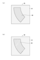
- (a) and (b) are diagrams schematically showing the inside of the cochlea of the ear in which the hearing device according to the present embodiment is placed.
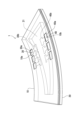
- FIG. 1 is a perspective view showing a hearing device according to the present embodiment.
- FIG. 1 is a plan view showing a hearing device according to the present embodiment.
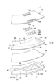
- FIG. 1 is an exploded perspective view showing the hearing device according to the present embodiment.
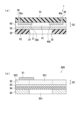
- (a) is a schematic cross-sectional view taken along the VIA-VIA line in FIG. 4.
- (b) is a schematic cross-sectional view showing a hearing device according to a comparative example.
- FIG. 1 is a block diagram showing a hearing system including a hearing device according to the present embodiment. It is an exploded perspective view showing a hearing device concerning a modification of this embodiment.
- FIG. 1 is a cross-sectional view schematically showing the structure of an ear EA in which a hearing device 1 according to an embodiment of the present invention is placed.
- the ear EA which is a sensory organ that controls hearing, is divided into an outer ear 100, a middle ear 200, and an inner ear 300. Sound waves generated outside the ear EA are guided to the external auditory canal 101 and vibrate the eardrum 102 at the far end of the external auditory canal 101.
- the auditory ossicles 201 which are made up of three bones, transmit the vibrations of the eardrum 102 to the inside of the cochlea 301.
- the cochlea 301 converts the vibration of the eardrum 102 (sound information) caused by sound waves into a nerve signal, and transmits the nerve signal to the auditory center 400 of the cerebrum via the auditory nerve 401.
- the cochlea 301 is a spiral tube having a substantially conical shape and having approximately two and a half turns (approximately 900 degrees).
- the inside of the cochlea 301 is divided into three regions: the scala vestibule, the scala media, and the scala tympani, and each region is filled with lymph fluid.
- the scala vestibule and the scala media are separated by Reisner's membrane, and the scala media and the scala tympani are separated by a basilar membrane 302 (see FIG. 2, which will be described later).
- the size of the human cochlea 301 is, for example, about the size of a human little finger nail.
- the length of the human cochlea 301 when stretched out is, for example, about 30 mm.
- Ear EA is classified into conductive type and sensorineural type. Since the outer ear 100 and the middle ear 200 are organs for transmitting sound, they are classified as sound conducting systems. The inner ear 300 and auditory center 400 are organs for sensing sound, and are therefore classified as a sensorineural system.
- FIGS. 2(a) and 2(b) are diagrams schematically showing the inside of the cochlea 301.
- FIGS. 2(a) and 2(b) schematically show a state in which the spiral cochlea 301 is stretched linearly.
- the cochlea 301 has a basement membrane 302.
- the basement membrane 302 has a substantially trapezoidal shape when the basement membrane 302 is stretched linearly. Therefore, the width W1 of the proximal end 302a of the basement membrane 302 is smaller than the width W2 of the distal end 302b of the basement membrane 302.
- a proximal end 302a of the basilar membrane 302 is located on the cochlear fundus 301a (FIG. 1) side of the cochlea 301.
- the distal end 302b of the basement membrane 302 is located on the cochlear apex 301b (FIG. 1) side of the cochlea 301.
- the basilar membrane 302 vibrates due to sound waves propagating through the outer ear 100 and the middle ear 200.
- the basement membrane 302 has a characteristic frequency at which it is likely to vibrate in each part, and strong vibrations (strong response) occur in the parts corresponding to the frequency of the sound wave propagating to the basement membrane 302. Specifically, in the basement membrane 302, the higher the frequency of the sound wave, the stronger the portion on the proximal end 302a side vibrates. On the other hand, in the basement membrane 302, the lower the frequency of the sound wave, the more the portion on the tip 302b side vibrates.
- Humans distinguish the pitch of sound (frequency of sound waves) using the basilar membrane 302, and can distinguish sounds between 20 Hz and 20,000 Hz.
- the cochlea 301 has the organ of Corti 303 on the basement membrane 302.
- the organ of Corti 303 has a large number of hair cells 304.
- a large number of hair cells 304 are arranged on the basement membrane 302.
- the inner hair cells 305 on the basement membrane 302 When the basement membrane 302 vibrates, the inner hair cells 305 on the basement membrane 302 also vibrate. As a result, the inner hair cells 305 convert the vibration of the basilar membrane 302 into a nerve signal, which is an electrical signal, and transmit the nerve signal to the auditory nerve 401. Specifically, the inner hair cells 305 present in a region of the basilar membrane 302 that vibrates strongly due to the vibration of the characteristic frequency convert the vibration of the region into a nerve signal, and transmit the nerve signal to the auditory nerve 401. That is, the sound waves are sensed at each characteristic frequency by each part of the basement membrane 302 and the inner hair cells 305 present in each part. In addition, the outer hair cells 306 perform contraction movements to amplify weak sound stimulation while suppressing excessive sound stimulation, thereby increasing auditory sensitivity.
- a hearing device 1 can be placed inside a human body. Humans are an example of "mammals.” Note that the hearing device 1 may be placed inside the body of an animal such as a pet, for example.
- the hearing device 1 is placed inside the cochlea 301 (specifically, the scala tympani).
- the hearing device 1 mimics the basilar membrane 302 of the cochlea 301 and the organ of Corti 303. Therefore, the auditory device 1 converts vibrations caused by sound waves (vibrations transmitted from the eardrum 102) into electrical signals (nerve signals) for each frequency, and transmits each electrical signal to the auditory nerve 401. That is, the auditory device 1 replaces the functions of the basilar membrane 302 of the cochlea 301 and the organ of Corti 303.
- the auditory device 1 in the cochlea 301, a person's ability to recognize sounds can be improved even when the functions of the basilar membrane 302 and organ of Corti 303 of the cochlea 301 are reduced.
- the hearing device 1 in the cochlea 301 of a person with sensorineural hearing loss, it is possible to give the person with sensorineural hearing loss the same sense of hearing as a person with normal hearing.
- sensorineural hearing loss is a hearing impairment caused by functional decline of the cochlea 301 and/or the auditory nerve 401. For example, with mild sensorineural hearing loss, sounds may suddenly become indistinct. For example, people with severe sensorineural hearing loss may be unable to recognize sounds. By applying the hearing device 1 to people with sensorineural hearing loss, their ability to recognize sounds can be improved. Therefore, the hearing device 1 is sometimes referred to as an "artificial hearing epithelium.”
- the hearing device 1 has a shape that follows the shape of the cochlea 301. Specifically, the hearing device 1 (surface layer 10, piezoelectric film 60, electrode layer 50, and substrate 20, which will be described later) extends in a spiral shape. In this case, the function of the auditory device 1 can be approximated by the functions of the basilar membrane 302 and organ of Corti 303, so that human sound recognition ability can be further improved. For example, the hearing device 1 has a spiral shape with approximately two and a half turns (approximately 900 degrees).
- the shape of the hearing device 1 is not particularly limited. An example in which the auditory device 1 has a substantially arc shape will be described below.
- FIG. 3 is a perspective view showing the hearing device 1.
- FIG. 4 is a plan view showing the hearing device 1.
- the hearing device 1 has, for example, a substantially arc shape.
- the hearing device 1 has a substantially arcuate band shape.
- the width W of the hearing device 1 is, for example, approximately 500 ⁇ m.
- the hearing device 1 includes a surface layer 10, a substrate 20, and a plurality of recognition electrodes 30.
- the hearing device 1 further comprises a control electrode 40 .
- the recognition electrode 30 corresponds to an example of an "electrode.”
- the surface layer 10 exposes at least a portion of each of the plurality of recognition electrodes 30.
- the surface layer 10 exposes a portion of each of the plurality of recognition electrodes 30.
- the recognition electrode 30 is an electrode for allowing humans to recognize sound. The details of the function of the recognition electrode 30 will be described later.
- the surface layer 10 exposes at least a portion of each of the plurality of control electrodes 40.
- the surface layer 10 exposes a portion of each of the plurality of control electrodes 40.
- the control electrode 40 is an electrode for controlling the vibration of the piezoelectric film 60 (see FIG. 5, which will be described later). The details of the function of the control electrode 40 will be described later.
- the recognition electrode 30 has a first end 30a and a second end 30b. Furthermore, the control electrode 40 has a first end 40a and a second end 40b. Furthermore, the surface layer 10 has a plurality of first openings 10a and a plurality of second openings 10b.
- the plurality of first openings 10a are provided corresponding to the plurality of first ends 30a, respectively.
- the first end 30a is exposed from the first opening 10a.
- the second end portion 30b is covered with the surface layer 10.
- the plurality of second openings 10b are provided corresponding to the plurality of first ends 40a, respectively.
- the first end 40a is exposed through the second opening 10b.
- the second end portion 40b is covered with the surface layer 10.
- the substrate 20 has a long hole 21.
- the direction D1 in which the elongated hole 21 extends will be referred to as the "extension direction D1.”
- the extension direction D1 is a direction along the arc shape.
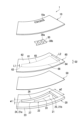
- FIG. 5 is an exploded perspective view showing the hearing device 1.
- the hearing device 1 further includes an electrode layer 50 and a piezoelectric film 60.
- the surface layer 10, the plurality of recognition electrodes 30, the piezoelectric film 60, the electrode layer 50, and the substrate 20 are arranged in this arrangement in the thickness direction D2 of the piezoelectric film 60.
- the surface layer 10, the plurality of recognition electrodes 30, the piezoelectric film 60, the electrode layer 50, and the substrate 20 are laminated in this order in the thickness direction D2 of the piezoelectric film 60.
- the plurality of control electrodes 40 are arranged at the same level as the plurality of recognition electrodes 30.
- the surface layer 10 covers the second ends 30b of the plurality of recognition electrodes 30, the second ends 40b of the plurality of control electrodes 40, and the piezoelectric film 60 from one side in the thickness direction D2 of the piezoelectric film 60. That is, the surface layer 10 covers the second ends 30b of the plurality of recognition electrodes 30, the second ends 40b of the plurality of control electrodes 40, and the piezoelectric film 60 from the opposite side of the electrode layer 50.
- the surface layer 10 has a substantially arc shape.
- the plurality of first openings 10a are arranged along the extension direction D1.
- the plurality of second openings 10b are arranged along the extension direction D1.
- the plurality of recognition electrodes 30 are in contact with the piezoelectric film 60 on one side in the thickness direction D2 of the piezoelectric film 60.
- the plurality of recognition electrodes 30 are arranged at intervals along the extension direction D1.
- the plurality of recognition electrodes 30 are arranged at regular intervals along the extension direction D1.
- the plurality of recognition electrodes 30 may be arranged at irregular intervals along the extension direction D1.
- the second end portion 30b is arranged between the surface layer 10 and the piezoelectric film 60.
- the plurality of control electrodes 40 are in contact with the piezoelectric film 60 on one side in the thickness direction D2 of the piezoelectric film 60.
- the plurality of control electrodes 40 are arranged at intervals along the extension direction D1.
- the plurality of control electrodes 40 are arranged at regular intervals along the extension direction D1.
- the plurality of control electrodes 40 may be arranged at irregular intervals along the extension direction D1.
- the second end portion 40b is arranged between the surface layer 10 and the piezoelectric film 60.
- the recognition electrode 30 and the control electrode 40 are spaced apart and face each other in a direction intersecting the extension direction D1. Specifically, the second end 30b and the second end 40b face each other.
- the electrode layer 50 contacts the piezoelectric film 60 on the other side of the piezoelectric film 60 in the thickness direction D2. That is, the electrode layer 50 contacts the piezoelectric film 60 from the opposite side of the surface layer 10.
- the electrode layer 50 has a substantially arc shape.
- the electrode layer 50 covers the piezoelectric film 60 on the other side of the piezoelectric film 60 in the thickness direction D2. That is, the electrode layer 50 covers the piezoelectric film 60 from the side opposite to the surface layer 10.
- the substrate 20 supports the piezoelectric film 60 from the other side in the thickness direction D2 of the piezoelectric film 60 via the electrode layer 50.
- the substrate 20 is in contact with the electrode layer 50 from the other side of the piezoelectric film 60 in the thickness direction D2.
- the substrate 20 has a substantially arc shape.
- the substrate 20 has an inner edge 22 and an outer edge 23.
- the outer edge portion 23 is an edge region along the outer periphery of the substrate 20.
- Inner edge portion 22 is an edge region along the inner circumference of substrate 20 .
- the inner edge portion 22 has a base end portion 24 , a distal end portion 25 , a first side portion 26 , and a second side portion 27 .
- the base end portion 24 is one end portion of the inner edge portion 22 in the extension direction D1.
- the base end portion 24 has a substantially straight shape.
- the shape of the base end portion 24 is not particularly limited, and may be curved, for example.
- the tip portion 25 is the other end of the inner edge portion 22 in the extension direction D1.
- the tip portion 25 has a substantially straight shape.
- the shape of the tip portion 25 is not particularly limited, and may be curved, for example.
- the first side portion 26 is curved. Note that the first side portion 26 may extend substantially linearly, for example.
- the first side portion 26 connects one end of the proximal end portion 24 in the direction intersecting the extending direction D1 and one end of the distal end portion 25 in the direction intersecting the extending direction D1.
- the second side portion 27 is curved. Note that the second side portion 27 may extend substantially linearly, for example.
- the second side portion 27 connects the other end of the proximal end portion 24 in the direction intersecting the extending direction D1 and the other end of the distal end portion 25 in the direction intersecting the extending direction D1.
- the width w1 of the base end portion 24 is smaller than the width w2 of the distal end portion 25. Therefore, the inner edge portion 22 has a curved, substantially trapezoidal shape.
- the inner edge portion 22 defines the shape of the elongated hole 21 . Therefore, the long hole 21 has a curved, substantially trapezoidal shape. That is, the width w1 of one end 21a of the long hole 21 in the extending direction D1 is smaller than the width w2 of the other end 21b of the long hole 21 in the extending direction D1. Note that the widths w1 and w2 indicate widths in a direction intersecting the extension direction D1.
- Each of the inner edges 22 and slots 21 mimics the shape of the basement membrane 302 (FIG. 2).
- the piezoelectric film 60 converts the vibration of the piezoelectric film 60 into an electrical signal. Specifically, when the piezoelectric film 60 vibrates, a voltage (electrical signal) corresponding to the distortion caused by the vibration is generated in the piezoelectric film 60. In other words, the piezoelectric film 60 has a piezoelectric effect.
- the piezoelectric film 60 has a substantially arc shape.
- the piezoelectric film 60 has a vibration sensing area 61 and a frame area 62.
- the first end 30 a of the recognition electrode 30 and the first end 40 a of the control electrode 40 contact the frame region 62 .
- the second end 30b of the recognition electrode 30 and the second end 40b of the control electrode 40 contact the vibration sensing region 61.
- the frame area 62 surrounds the vibration sensing area 61. Frame region 62 is supported by substrate 20 via electrode layer 50 . Therefore, frame region 62 does not substantially vibrate.
- the vibration sensing area 61 is an area that senses vibrations. Vibration sensing region 61 mimics the shape and function of basement membrane 302 (FIG. 2). Therefore, vibration sensing region 61 vibrates due to sound waves propagating through outer ear 100 and middle ear 200. Specifically, the vibration sensing region 61 vibrates according to the frequency of external sound waves (specifically, vibrations transmitted from the eardrum 102 by external sound waves), and converts the vibrations into electrical signals for each frequency.
- external sound waves specifically, vibrations transmitted from the eardrum 102 by external sound waves
- the vibration sensing area 61 has a resonant frequency (characteristic frequency) at which each part of the vibration sensing area 61 is likely to vibrate, and external sound waves (specifically, external sound waves cause the eardrum 102 to Resonance (strong vibration) occurs at the part corresponding to the frequency (resonance frequency) of the vibration transmitted from the resonant frequency (characteristic frequency) at which each part of the vibration sensing area 61 is likely to vibrate, and external sound waves (specifically, external sound waves cause the eardrum 102 to Resonance (strong vibration) occurs at the part corresponding to the frequency (resonance frequency) of the vibration transmitted from the
- the resonance frequency changes along the extension direction D1. That is, in the vibration sensing region 61, the smaller the width of the vibration sensing region 61, the higher the resonance frequency. On the other hand, in the vibration sensing region 61, the larger the width of the vibration sensing region 61, the lower the resonance frequency. In this way, the vibration sensing region 61 performs frequency decomposition (frequency discrimination) of sound waves and mimics the basilar membrane 302.
- the resonant portion (strongly vibrated portion) of the vibration sensing region 61 converts the vibration having the resonant frequency into an electrical signal. Then, the recognition electrode 30 in contact with the resonant part of the vibration sensing region 61 transmits an electric signal corresponding to the vibration having the resonant frequency to the auditory nerve 401. As a result, humans can recognize external sounds. In this way, vibration sensing region 61 and recognition electrode 30 mimic inner hair cells 305.
- the vibration sensing region 61 faces the long hole 21 in the thickness direction D2 of the piezoelectric film 60 with the electrode layer 50 interposed therebetween. Therefore, the shape of the vibration sensing region 61 is substantially the same as the shape of the elongated hole 21.
- the vibration sensing region 61 has a proximal end 63 , a distal end 64 , a first side 65 , and a second side 66 .
- the base end portion 63 is one end portion of the vibration sensing region 61 in the extension direction D1.
- the base end portion 63 has a substantially straight shape.
- the shape of the base end portion 63 is not particularly limited, and may be curved, for example.
- the tip portion 64 is the other end of the vibration sensing region 61 in the extension direction D1.
- the tip portion 64 has a substantially straight shape.
- the shape of the tip portion 64 is not particularly limited, and may be curved, for example.
- the first side portion 65 is curved. Note that the first side portion 65 may extend substantially linearly, for example.
- the first side portion 65 connects one end of the proximal end portion 63 in the direction intersecting the extending direction D1 and one end of the distal end portion 64 in the direction intersecting the extending direction D1.
- the second side portion 66 is curved. Note that the second side portion 66 may extend substantially linearly, for example.
- the second side portion 66 connects the other end of the proximal end portion 63 in the direction intersecting the extending direction D1 and the other end of the distal end portion 64 in the direction intersecting the extending direction D1.
- the width L1 of the proximal end portion 63 is shorter than the width L2 of the distal end portion 64. Therefore, the vibration sensing area 61 has a curved, substantially trapezoidal shape. Note that the widths L1 and L2 indicate widths in a direction intersecting the extension direction D1.
- the base end 63 corresponds to the base end 302a of the basement membrane 302.
- the tip 64 corresponds to the tip 302b of the basement membrane 302. Therefore, the hearing device 1 is placed on the side where the tip 64 of the vibration sensing region 61 faces the cochlear apex 301b (FIG. 1).
- the vibration sensing region 61 In the vibration sensing region 61, the closer the region is to the base end 63, the higher the resonant frequency is. That is, in the vibration sensing region 61, the higher the frequency of the sound wave, the stronger the portion on the base end 63 side vibrates. On the other hand, in the vibration sensing region 61, the closer the portion is to the tip 64, the lower the resonance frequency becomes. That is, in the vibration sensing region 61, the lower the frequency of the sound wave, the more the portion on the tip 64 side vibrates. In this way, the vibration sensing region 61 performs frequency decomposition (frequency discrimination) of sound waves.
- the surface layer 10 covers the piezoelectric film 60. Therefore, even if the hearing device 1 is placed inside the cochlea 301 and immersed in lymph fluid, the durability of the piezoelectric film 60 can be improved. In other words, the durability of the piezoelectric film 60 within the cochlea 301 (in the body) can be improved.
- FIG. 6(a) is a schematic cross-sectional view taken along the line VIA-VIA in FIG.
- FIG. 6(b) is a schematic cross-sectional view showing a hearing device 600 according to a comparative example.
- the material of the surface layer 10 and the substrate 20 is preferably a synthetic resin.
- the synthetic resin is, for example, epoxy resin, phenol resin, PBT (polybutylene terephthalate), or PPS (polyphenylene sulfide).
- the material of the surface layer 10 and the substrate 20 may be photoresist.
- the photoresist is a negative photoresist or a positive photoresist.
- the material of the surface layer 10 and the substrate 20 is "SU-8".
- "SU-8" is a negative photoresist based on epoxy resin. Note that the thickness of each of the surface layer 10 and the substrate 20 is, for example, about 1 ⁇ m.
- the materials of the recognition electrode 30, control electrode 40, and electrode layer 50 are electrical conductors.
- the electrical conductor is, for example, a metal.
- Each of the recognition electrode 30, the control electrode 40, and the electrode layer 50 may be composed of a single layer of metal, or may be composed of multiple layers of metal.
- the metal is, for example, platinum, gold, or silver.
- each of the recognition electrode 30, control electrode 40, and electrode layer 50 is composed of three layers, for example, a gold layer is sandwiched between two titanium layers. Note that the thickness of each of the recognition electrode 30, the control electrode 40, and the electrode layer 50 is, for example, about 100 nm.
- the material of the piezoelectric film 60 is a piezoelectric material.
- the piezoelectric material is preferably an organic piezoelectric material. This is because it is more compatible with living organisms.
- the organic piezoelectric material is P(VDF-TrFE).
- P(VDF-TrFE) is polyvinylidene fluoride trifluoroethylene. That is, P(VDF-TrFE) is a copolymer of vinylidene fluoride (VDF) and trifluoroethylene (TrFE).
- Other organic piezoelectric materials are, for example, PVDF (polyvinylidene fluoride) or PLA (polylactic acid).
- the material of the piezoelectric film 60 may be an inorganic piezoelectric material.
- An inorganic piezoelectric material for example, PZT (lead zirconate titanate), ZnO (zinc oxide), AlN (aluminum nitride), or KNN (potassium sodium niobate).
- the thickness of the piezoelectric film 60 is, for example, about 1 ⁇ m.
- the hearing device 600 includes a recognition electrode 91, a piezoelectric film 92, an electrode layer 93, a protective layer 94, and a substrate 95.
- Piezoelectric film 92 has a vibration sensing area 921 and a frame area 922.
- the boundary between the vibration sensing area 921 and the frame area 922 is shown with a broken line for easy understanding.
- the substrate 95 has a long hole 951.
- the long hole 951 has a curved, substantially trapezoidal shape in plan view.
- the recognition electrode 91, piezoelectric film 92, electrode layer 93, protective layer 94, and substrate 95 are arranged in this arrangement in the thickness direction D2 of the piezoelectric film 92.
- the material of the recognition electrode 91 and the electrode layer 93 is platinum.
- the material of the piezoelectric film 92 is P(VDF-TrFE).
- the material of the protective layer 94 is silicon monoxide (SiO).
- the protective layer 94 protects the piezoelectric film 92 from being damaged when the long hole 951 is formed in the substrate 95 by deep RIE (Reactive Ion Etching).
- the material of the substrate 95 is silicon (Si).
- the long hole 951 in the substrate 95 is formed by performing deep RIE on the silicon substrate. Since deep RIE is a high-cost microfabrication technique, the manufacturing cost of the hearing device 600 according to the comparative example is high.
- the silicon substrate is a semi-metal and a relatively hard substance. Therefore, it is necessary to perform deep RIE for microfabrication of a silicon substrate, which increases manufacturing costs. Furthermore, it is difficult to improve the yield due to the difficulty of processing by deep RIE. Furthermore, it is difficult to cut out the hearing device 600 from the silicon substrate, which further increases the manufacturing cost of the hearing device 600.
- the long holes 21 can be easily formed in the substrate 20 without performing deep RIE.
- the long holes 21 can be easily formed in the substrate 20 by photolithography or injection molding.
- the manufacturing cost of the hearing device 1 can be reduced and the yield can be improved.
- the protective layer 94 of the comparative example is not necessary.
- the material of the surface layer 10 and the substrate 20 is synthetic resin, the surface layer 10 and the substrate 20 can be easily formed by photolithography or injection molding. Therefore, mass production of the hearing device 1 is facilitated while reducing manufacturing costs and improving yield.
- the physical property values indicating the mechanical properties of the surface layer 10 are similar to the physical property values indicating the mechanical properties of the piezoelectric film 60. Therefore, the vibration propagation characteristics of the surface layer 10 and the piezoelectric film 60 are similar. As a result, the vibration of the vibration sensing region 61 of the piezoelectric film 60 is The vibration of the basement membrane 302 can be brought closer to the vibration. Therefore, the hearing device 1 can allow humans to recognize higher quality sounds. Further, when the physical property values indicating the mechanical properties of the surface layer 10 are similar to the physical property values indicating the mechanical properties of the piezoelectric film 60, performance evaluation and performance prediction of the auditory device 1 becomes easy.
- the physical property value indicating the mechanical properties of the surface layer 10 is the density and/or elastic modulus of the surface layer 10.
- the physical property value indicating the mechanical properties of the piezoelectric film 60 is the density and/or elastic modulus of the piezoelectric film 60.
- the density of the surface layer 10 approximates the density of the piezoelectric film 60.
- the density of the surface layer 10 is preferably within ⁇ 20% of the density of the piezoelectric film 60, and more preferably within ⁇ 10% of the density of the piezoelectric film 60.
- the piezoelectric film 60 is made of P (VDF-TrFE)
- the density of the piezoelectric film 60 is 1780 kg/m 3
- the surface layer 10 is made of SU-8
- the density of the surface layer 10 is 1600 kg/m 3 ⁇ It is 1800 kg/m 3 .
- the elastic modulus of the surface layer 10 approximates the elastic modulus of the piezoelectric film 60.
- the elastic modulus of the surface layer 10 is preferably (1/20) times or more and 20 times or less the elastic modulus of the piezoelectric film 60, and (1/10) times or more the elastic modulus of the piezoelectric film 60. More preferably, it is 10 times or less.
- the elastic modulus of the piezoelectric film 60 is about 5 GPa. That is, the elastic modulus of the piezoelectric film 60 is, for example, 1 GPa or more and 10 GPa or less.
- the elastic modulus of the surface layer 10 is about 2.7 GPa.
- the density of the surface layer 10 approximates the density of the piezoelectric film 60, or the elastic modulus of the surface layer 10 approximates the elastic modulus of the piezoelectric film 60.
- the density of the surface layer 10 approximates the density of the piezoelectric film 60, and the elastic modulus of the surface layer 10 approximates the elastic modulus of the piezoelectric film 60.
- a hearing device manufacturing method is performed by a hearing device manufacturing system.
- the hearing device manufacturing system includes one or more cleaning devices, one or more vacuum deposition devices, one or more spin coaters, one or more baking devices, one or more exposure devices, one or more developing devices, one or more sputtering devices, and one or more a removal device, and one or more etching devices.
- FIGS. 7 to 10 are diagrams showing a hearing device manufacturing method for manufacturing the hearing device 1.
- the hearing device manufacturing method includes steps S1 to S8.
- step S1 a glass substrate 80 is prepared. Then, the cleaning device of the auditory device manufacturing system cleans the glass substrate 80 with an organic solvent.
- the organic solvent is, for example, isopropyl alcohol (IPA).
- the cleaning time is, for example, 5 minutes.
- the hearing device manufacturing system produces a metal film 81 on the glass substrate 80.
- the metal film 81 is produced by depositing metal onto the glass substrate 80 using a vacuum deposition apparatus.
- the metal film 81 may be a single layer film or a multilayer film.
- the metal film 81 is a film made of three metal layers.
- chromium is deposited on the glass substrate 80 to form a chromium film.
- gold is deposited on the chromium film to produce a gold film.
- chromium is deposited on the gold film to produce a chromium film.
- a metal film 81 made of three metal layers is produced.
- the thickness of the chromium film is about 70 nm
- the thickness of the gold film is about 140 nm.
- the hearing device manufacturing system produces the surface layer 10.
- the surface layer 10 is made of synthetic resin.
- the synthetic resin is, for example, SU-8.
- the surface layer 10 is produced by photolithography. Photolithography is, for example, maskless lithography.
- the spin coater applies a synthetic resin material onto the metal film 81 by spin coating.
- spin coating is performed at 500 rpm for 5 seconds and then at 4000 rpm for 30 seconds.
- the baking device bakes the synthetic resin material applied onto the metal film 81. For example, bake at 95 degrees for 3 minutes.
- a pattern corresponding to the surface layer 10 is exposed to the baked synthetic resin material using an exposure device (specifically, an LED drawing device).
- the exposed portion of the baked synthetic resin material is cured. Note that the pattern may be exposed using a photomask.
- the baking device bakes the pattern-exposed synthetic resin material. For example, after baking at 65 degrees for 1 minute, baking at 95 degrees for 2 minutes is performed.
- the developing device develops the baked synthetic resin material.
- the baking device hard bakes the developed synthetic resin material. For example, perform a hard bake at 200 degrees for 5 minutes.
- the surface layer 10 of synthetic resin is formed on the metal film 81.
- the thickness of the surface layer 10 is, for example, about 1 ⁇ m.
- step S4 the auditory device manufacturing system produces a plurality of recognition electrodes 30 and a plurality of control electrodes 40. Specifically, a plurality of recognition electrodes 30 and a plurality of control electrodes 40 are produced on the surface layer 10 by sputtering and lift-off of a metal material.
- the spin coater applies photoresist onto the surface layer 10 by spin coating.
- the photoresist is, for example, AZ5214E.
- spin coating is performed at 5000 rpm for 30 seconds.
- the baking device bakes the photoresist.
- the patterns corresponding to the plurality of recognition electrodes 30 and the plurality of control electrodes 40 are exposed to the baked photoresist using an exposure device (specifically, an LED drawing device).
- an exposure device specifically, an LED drawing device.
- the solubility of exposed portions of a baked photoresist increases. Note that the pattern may be exposed using a photomask.
- the developing device develops the pattern-exposed photoresist.
- the sputtering device forms the plurality of recognition electrodes 30 and the plurality of control electrodes 40 by sputtering a metal material.
- a removal device removes excess photoresist.
- the thickness of each of the recognition electrode 30 and the control electrode 40 is, for example, about 100 nm.
- the hearing device manufacturing system manufactures the piezoelectric film 60.
- the piezoelectric film 60 is produced by covering the surface layer 10, the plurality of recognition electrodes 30, and the plurality of control electrodes 40 with a piezoelectric material.
- the piezoelectric material is, for example, P(VDF-TrFE).
- the spin coater coats the piezoelectric material on the surface layer 10, the plurality of recognition electrodes 30, and the plurality of control electrodes 40 by spin coating.
- a piezoelectric material solution is applied onto the surface layer 10, the plurality of recognition electrodes 30, and the plurality of control electrodes 40 by spin coating.
- the solution of the piezoelectric material is, for example, a solution containing P(VDF-TrFE) as a solute and DEC (diethyl carbonate) as a solvent.
- spin coating is performed at 1000 rpm for 30 seconds.
- the baking device bakes the piezoelectric material solution. For example, bake at 130 degrees for 2 minutes.
- a piezoelectric film 60 is formed on the surface layer 10, the plurality of recognition electrodes 30, and the plurality of control electrodes 40.
- the thickness of the piezoelectric film 60 is, for example, about 1 ⁇ m.
- step S6 the hearing device manufacturing system produces the electrode layer 50.
- a sputtering device forms the electrode layer 50 on the piezoelectric film 60 by sputtering a metal material.
- the hearing device manufacturing system manufactures the substrate 20.
- the substrate 20 is made of synthetic resin.
- the synthetic resin is, for example, SU-8.
- the substrate 20 is manufactured by photolithography. Photolithography is, for example, maskless lithography.
- the spin coater applies a synthetic resin material onto the electrode layer 50 by spin coating.
- spin coating is performed at 500 rpm for 5 seconds and then at 800 rpm for 30 seconds.
- the baking device bakes the synthetic resin material applied onto the electrode layer 50. For example, bake at 95 degrees for 1 hour.
- a pattern corresponding to the substrate 20 having the long holes 21 is exposed to the baked synthetic resin material using an exposure device (specifically, an LED drawing device).
- the exposed portion of the baked synthetic resin material is cured. Note that the pattern may be exposed using a photomask.
- the baking device bakes the pattern-exposed synthetic resin material. For example, after baking at 65 degrees for 1 minute, baking at 95 degrees for 10 minutes is performed.
- the developing device develops the baked synthetic resin material.
- the baking device hard bakes the developed synthetic resin material to crystallize the piezoelectric material. For example, hard bake at 130 degrees for 2 hours.
- the synthetic resin substrate 20 having the long holes 21 is formed on the electrode layer 50.
- the thickness of the substrate 20 is, for example, about 1 ⁇ m.
- step S8 the etching apparatus of the hearing device manufacturing system peels the hearing device 1 from the metal film 81 of the glass substrate 80 using an etching solution for the metal film 81. As a result, the hearing device 1 is completed.
- the piezoelectric film 60 is covered with the surface layer 10. Therefore, even if the hearing device 1 is placed inside the cochlea 301 and immersed in lymph fluid, the durability of the piezoelectric film 60 can be improved.
- the surface layer 10 and the substrate 20 are formed of synthetic resin, and the long holes 21 of the substrate W are formed by photolithography. Therefore, the long holes 21 can be easily formed in the substrate 20 without performing deep RIE.
- a surface layer 10 is formed in step S3.
- step S4 a plurality of recognition electrodes 30 and a plurality of control electrodes 40 are formed on the surface layer 10.
- the piezoelectric film 60 is formed by covering the surface layer 10, the plurality of recognition electrodes 30, and the plurality of control electrodes 40 with a piezoelectric material.
- step S6 the electrode layer 50 is formed on the piezoelectric film 60.
- step S7 the substrate 20 is formed on the electrode layer 50. In this way, the auditory device 1 can be manufactured by performing at least steps S3 to S7.
- the synthetic resin forming the surface layer 10 is an elastic body in which energy elasticity is more dominant than entropic elasticity.
- the synthetic resin forming the surface layer 10 is an elastic body having a higher elastic modulus than rubber. Therefore, in step S8, the hearing device 1 can be easily peeled off from the metal film 81.
- the elastic modulus of the rubber is, for example, 1 MPa or more and 10 MPa or less at room temperature.
- entropic elasticity refers to rubber elasticity, and is the property that when an external force is applied to an elastic body, the elastic body absorbs energy and tries to return to its original state.
- Energy elasticity refers to the property that when an external force is applied to an elastic body, energy is not stored in the elastic body but is converted into destruction of the elastic body.
- FIG. 11 is a block diagram showing the auditory system SYS.
- the hearing system SYS includes a hearing device 1 and a controller 2.
- Controller 2 controls hearing device 1 .
- the controller 2 is, for example, a microcomputer.
- the controller 2 includes a plurality of amplifier circuits 4 and a processing section 3.
- the amplifier circuit 4 includes, for example, an amplifier, a resistance element, and a capacitor.
- the processing unit 3 includes, for example, a processor, a memory, and a power source.
- Controller 2 is placed, for example, in tympanic cavity 202 (FIG. 1).
- the plurality of recognition electrodes 30 are respectively connected to the plurality of amplifier circuits 4. Moreover, the plurality of recognition electrodes 30 are each connected to the auditory nerve 401 by a plurality of signal lines. Specifically, the first end 30a of the recognition electrode 30 is connected to the amplifier circuit 4 and the auditory nerve 401.
- the plurality of amplifier circuits 4 are connected to the processing section 3.
- the plurality of control electrodes 40 are connected to the processing section 3. Specifically, the first end 40a of the control electrode 40 is connected to the processing section 3.
- the electrode layer 50 functions as a ground electrode and is connected to the controller 2. Note that the electrode layer 50 may be electrically floating.
- vibration transmitted from the eardrum 102 to each part of the vibration sensing region 61 of the piezoelectric membrane 60 is converted into an electric signal SGa for each resonance frequency (characteristic frequency) by each part of the vibration sensing region 61.
- Each electrical signal SGa is then transmitted to the auditory nerve 401 from the recognition electrode 30 in contact with each region.
- vibration sensing region 61 mimics basement membrane 302 and vibration sensing region 61 and recognition electrode 30 mimic inner hair cells 305.
- the processing unit 3 performs feedback control on the vibration sensing region 61 of the piezoelectric film 60 to more precisely reproduce the functions of the basement membrane 302 and hair cells 304.
- each electrical signal SGa is output from each recognition electrode 30 to each amplifier circuit 4.
- the plurality of amplifier circuits 4 each amplify the plurality of electrical signals SGa and output the plurality of amplified signals SGb to the processing section 3.
- the processing unit 3 performs predetermined processing based on each amplified signal SGb to generate each control signal SGc.
- the predetermined process is a process for imitating the functions of the basilar membrane 302 and organ of Corti 303 of a normal hearing person.
- the predetermined process is a process of generating the control signal SGc so as to amplify weak vibrations (weak sound stimulation) and suppress excessive vibrations (excessive sound stimulation).
- the processing unit 3 outputs the plurality of control signals SGc to the plurality of control electrodes 40, respectively.
- Each control electrode 40 applies each control signal SGc to each part in the vibration sensing region 61 of the piezoelectric film 60. Therefore, each part of the vibration sensing region 61 vibrates according to the voltage value of each control signal SGc.
- each recognition electrode 30 transmits each electric signal SGa to the auditory nerve 401 according to the vibration of each part controlled by each control signal SGc. Therefore, humans can recognize sounds with a quality that is even closer to that of normal hearing people. In this way, the processing section 3 and control electrode 40 mimic outer hair cells 306.
- a hearing device 1A according to a modification of this embodiment will be described with reference to FIGS. 11 and 12.
- the modified example does not have the control electrode 40.
- the differences between the modified example and the above embodiment will be mainly explained.
- FIG. 12 is an exploded perspective view showing a hearing device 1A according to a modification.
- the hearing device 1A includes a surface layer 10, a plurality of recognition electrodes 30, a piezoelectric film 60, an electrode layer 50, and a substrate 20. Therefore, the hearing device 1A does not include the control electrode 40. Therefore, in the modified example, the processing section 3 of FIG. 11 is not provided, but a plurality of amplifier circuits 4 are provided. The plurality of recognition electrodes 30 are then connected to the plurality of amplifier circuits 4, respectively. Furthermore, each amplifier circuit 4 transmits the amplified signal SGb to the auditory nerve 401 through each signal line.
- the surface layer 10 may be produced by injection molding. Further, in step S7 shown in FIG. 10(a), the substrate 20 may be manufactured by injection molding. In this case, since a mold is used, the long holes 21 can be easily formed in the substrate 20 without performing deep RIE. As a result, the manufacturing cost of the hearing device 1 can be reduced and the yield can be improved. Furthermore, since the surface layer 10 and the substrate 20 can be easily formed by injection molding, mass production of the hearing device 1 becomes easy.
- the injection molding in step S3 and the injection molding in step S7 may be performed simultaneously.
- the surface layer 10 and the substrate 20 are formed by injection molding using the plurality of recognition electrodes 30, the plurality of control electrodes 40, and the piezoelectric film 60 on which the electrode layer 50 is formed as an insert product.
- step S3 shown in FIG. 8(a) the second opening 10b is not created in step S3 shown in FIG. 8(a). Further, in step S4 shown in FIG. 8(b), the control electrode 40 is not manufactured.
- the surface layer 10 and/or the substrate 20 may be formed of, for example, a semimetal or a metal.
- the material of the surface layer 10 or the substrate 20 is a synthetic resin. More preferably, both the surface layer 10 and the substrate 20 are made of synthetic resin.
- each of the recognition electrode 30 and the control electrode 40 can be changed. For example, it is made to have a thickness of about 10 ⁇ m.
- the length of the auditory devices 1 and 1A when stretched out is approximately 30 mm, which is the length when the cochlea 301 is stretched out, then each of the recognition electrodes 30 and the control electrodes 40 will be approximately 3000 pieces. Can be placed.
- the hearing devices 1, 1A can imitate the cochlea 301 with higher accuracy. Therefore, humans can recognize higher quality sounds using the hearing devices 1 and 1A.
- the present invention provides a hearing device and a method for manufacturing a hearing device, and has industrial applicability.
Landscapes
- Health & Medical Sciences (AREA)
- Engineering & Computer Science (AREA)
- Life Sciences & Earth Sciences (AREA)
- General Health & Medical Sciences (AREA)
- Physics & Mathematics (AREA)
- Otolaryngology (AREA)
- Veterinary Medicine (AREA)
- Biomedical Technology (AREA)
- Animal Behavior & Ethology (AREA)
- Acoustics & Sound (AREA)
- Public Health (AREA)
- Signal Processing (AREA)
- Heart & Thoracic Surgery (AREA)
- Vascular Medicine (AREA)
- Psychology (AREA)
- Biophysics (AREA)
- Neurosurgery (AREA)
- Pulmonology (AREA)
- Cardiology (AREA)
- Oral & Maxillofacial Surgery (AREA)
- Transplantation (AREA)
- Nuclear Medicine, Radiotherapy & Molecular Imaging (AREA)
- Radiology & Medical Imaging (AREA)
- Piezo-Electric Transducers For Audible Bands (AREA)
Abstract
聴覚デバイス(1)は、哺乳類の体内に配置することが可能である。聴覚デバイス(1)は、圧電膜(60)と、複数の認識電極(30)と、電極層(50)と、基板(20)と、表面層(10)とを備える。圧電膜(60)は、振動を電気信号に変換する。複数の認識電極(30)は、圧電膜(60)の厚み方向(D2)の一方側において、圧電膜(60)に接触する。電極層(50)は、圧電膜(60)の厚み方向(D2)の他方側において、圧電膜(60)に接触する。基板(20)は、長孔(21)を有し、電極層(50)を介して圧電膜(60)を支持する。表面層(10)は、電極層(50)の反対側から圧電膜(60)を覆い、複数の認識電極(30)の各々の少なくとも一部を露出させる。長孔(21)の延設方向(D1)の一方端部の幅(w1)は、長孔(21)の延設方向(D1)の他方端部の幅(w2)よりも小さい。
Description
本発明は、聴覚デバイス、及び、聴覚デバイス製造方法に関する。
非特許文献1に記載された人工蝸牛においては、シリコン基板上に、白金薄膜電極、P(VDF-TrFE)からなる圧電膜、及び、白金薄膜電極が、この配列で配置される。圧電膜は、蝸牛の基底膜を模倣した台形形状を有している。
Hirofumi SHINTAKU, Takashi TATENO, Nobuyoshi TSUCHIOKA, Harto TANUJAYA, Takayuki NAKAGAWA, Juichi ITO, and Satoyuki KAWANO, "Culturing Neurons on MEMS Fabricated P(VDF-TrFE) Films for Implantable Artificial Cochlea", Journal of Biomechanical Science and Engineering 5 (3), p.229-235, 2010
しかしながら、非特許文献1に記載された人工蝸牛では、圧電膜が露出している。従って、人工蝸牛を体内に配置したときに、圧電膜が体液(例えば、リンパ液)に接触することにより、圧電膜の耐久性が低下する可能性がある。
本発明は上記課題に鑑みてなされたものであり、その目的は、体内において圧電膜の耐久性を向上できる聴覚デバイス、及び、聴覚デバイス製造方法を提供することにある。
本発明の一局面によれば、聴覚デバイスは、哺乳類の体内に配置することが可能である。聴覚デバイスは、圧電膜と、複数の電極と、電極層と、基板と、表面層とを備える。圧電膜は、振動を電気信号に変換する。複数の電極は、前記圧電膜の厚み方向の一方側において、前記圧電膜に接触する。電極層は、前記圧電膜の前記厚み方向の他方側において、前記圧電膜に接触する。基板は、長孔を有し、前記電極層を介して前記圧電膜を支持する。表面層は、前記電極層の反対側から前記圧電膜を覆い、前記複数の電極の各々の少なくとも一部を露出させる。前記長孔の延設方向の一方端部の幅は、前記長孔の前記延設方向の他方端部の幅よりも短い。
本発明の一態様においては、前記表面層及び前記基板の材料は、合成樹脂であることが好ましい。
本発明の一態様においては、前記表面層は、ゴムよりも弾性率が大きい弾性体であることが好ましい。
本発明の一態様においては、前記表面層の機械的性質を示す物性値は、前記圧電膜の機械的性質を示す物性値と近似していることが好ましい。
本発明の一態様においては、前記圧電膜は、螺旋状に延びることが好ましい。
本発明の他の局面によれば、聴覚デバイス製造方法において、哺乳類の体内に配置することの可能な聴覚デバイスを製造する。聴覚デバイス製造方法は、表面層を作製する工程と、複数の電極を作製する工程と、圧電膜を作製する工程と、電極層を作製する工程と、長孔を有する基板を作製する工程とを含む。前記長孔の延設方向の一方端部の幅は、前記長孔の前記延設方向の他方端部の幅よりも短い。前記表面層、前記複数の電極、前記圧電膜、前記電極層、及び、前記基板は、この配列で配置される。
本発明の一態様においては、前記表面層を作製する前記工程では、合成樹脂によって前記表面層を作製することが好ましい。前記基板を作製する前記工程では、合成樹脂によって前記基板を作製することが好ましい。
本発明の一態様においては、前記表面層を作製する前記工程では、フォトリソグラフィーまたは射出成形によって前記表面層を作製することが好ましい。前記基板を作製する前記工程では、フォトリソグラフィーまたは射出成形によって前記基板を作製することが好ましい。
本発明の一態様においては、前記表面層は、ゴムよりも弾性率が大きい弾性体であることが好ましい。
本発明の一態様においては、前記表面層の機械的性質を示す物性値は、前記圧電膜の機械的性質を示す物性値と近似していることが好ましい。
本発明の一態様においては、前記複数の電極を作製する前記工程では、前記表面層上に前記複数の電極を形成することが好ましい。前記圧電膜を作製する前記工程では、前記表面層及び前記複数の電極を圧電材料によって覆うことで前記圧電膜を形成することが好ましい。前記電極層を作製する前記工程では、前記圧電膜上に前記電極層を形成することが好ましい。前記基板を作製する前記工程では、前記電極層上に前記基板を形成することが好ましい。
本発明によれば、体内において圧電膜の耐久性を向上できる。
以下、本発明の実施形態について、図面を参照しながら説明する。なお、図中、同一または相当部分については同一の参照符号を付して説明を繰り返さない。
図1~図11を参照して、本発明の実施形態に係る聴覚デバイス1を説明する。まず、図1及び図2を参照して、耳EAについて説明する。図1は、本発明の実施形態に係る聴覚デバイス1が配置される耳EAの構造を概略的に示す断面図である。
図1に示すように、聴覚を司る感覚器である耳EAは、外耳100、中耳200及び内耳300に分けられる。耳EAの外で発生した音波は外耳道101に導かれ、外耳道101の奥端にある鼓膜102を振動させる。3個の骨からなる耳小骨201が鼓膜102の振動を蝸牛301の内部へ伝える。蝸牛301は、音波による鼓膜102の振動(音の情報)を神経信号に変換し、聴神経401を介して大脳の聴覚中枢400に神経信号を伝達する。蝸牛301は、略円錐形状を有し、約2回転半巻(約900度)の螺旋状の管である。
また、蝸牛301の内部は、前庭階、中央階及び鼓室階の3つの領域に分けられ、各領域はリンパ液で満たされている。前庭階と中央階とはライスネル膜により仕切られ、中央階と鼓室階とは基底膜302(後述の図2)により仕切られている。ヒトの蝸牛301の大きさは、例えば、ヒトの小指の爪程度である。ヒトの蝸牛301を引き延ばしたときの長さは、例えば、約30mmである。
耳EAは、伝音系と感音系とに分類される。外耳100及び中耳200は、音を伝達するための器官であるため、伝音系に分類される。内耳300及び聴覚中枢400は、音を感じるための器官であるため、感音系に分類される。
図2(a)及び図2(b)は、蝸牛301の内部を模式的に示す図である。図2(a)及び図2(b)では、螺旋状の蝸牛301が直線状に引き延ばされた状態を模式的に示している。
図2(a)及び図2(b)に示すように、蝸牛301は基底膜302を有する。基底膜302は,基底膜302が直線状に引き延ばされた状態において略台形形状を有する。従って、基底膜302の基端部302aの幅W1は、基底膜302の先端部302bの幅W2よりも小さい。基底膜302の基端部302aは、蝸牛301の蝸牛底301a(図1)側に位置する。基底膜302の先端部302bは、蝸牛301の蝸牛頂301b(図1)側に位置する。
基底膜302は、外耳100と中耳200とを介して伝播する音波によって振動する。基底膜302には、各部位において振動しやすい特徴周波数があり、基底膜302に伝播する音波の周波数に対応する部位で強く振動(強い応答)が生じる。具体的には、基底膜302では、音波の周波数が高い程、基端部302a側の部位が強く振動する。一方、基底膜302では、音波の周波数が低い程、先端部302b側の部位が大きく振動する。
ヒトは、音の高さ(音波の周波数)を基底膜302によって識別しており、20Hz~20000Hzの音を聞き分けることができる。
図2(a)に示すように、蝸牛301は、基底膜302上にコルチ器303を有する。コルチ器303は多数の有毛細胞304を有する。多数の有毛細胞304は、基底膜302上に整列している。有毛細胞304には、内有毛細胞305及び外有毛細胞306の2種類の細胞が存在している。
基底膜302が振動すると、基底膜302上の内有毛細胞305も振動する。その結果、内有毛細胞305は、基底膜302の振動を、電気信号である神経信号に変換し、神経信号を聴神経401に伝達する。具体的には、基底膜302において特徴周波数の振動によって強く振動する部位に存在する内有毛細胞305は、部位の振動を神経信号に変換し、神経信号を聴神経401に伝達する。つまり、音波は、基底膜302の各部位、及び、各部位に存在する内有毛細胞305によって、特徴周波数ごとに感知される。また、外有毛細胞306は、収縮運動を行って微弱な音刺激を増幅する一方で過大な音刺激を抑制しており、聴覚の感度を高めている。
各内有毛細胞305からの神経信号が聴神経401によって大脳500に伝達されることで、ヒトは、様々な周波数成分を有する音波を複合音として認識する。
次に、図1及び図3~図6を参照して、本実施形態に係る聴覚デバイス1を説明する。図1に示すように、聴覚デバイス1は、ヒトの体内に配置することが可能である。ヒトは「哺乳類」の一例に相当する。なお、聴覚デバイス1は、例えば、ペット等の動物の体内に配置されてもよい。
好ましくは、聴覚デバイス1は、蝸牛301の内部(具体的には、鼓室階)に配置される。聴覚デバイス1は、蝸牛301の基底膜302及びコルチ器303を模倣している。従って、聴覚デバイス1は、音波による振動(鼓膜102から伝わる振動)を周波数ごとに電気信号(神経信号)に変換して、各電気信号を聴神経401に伝達する。つまり、聴覚デバイス1は、蝸牛301の基底膜302及びコルチ器303の機能を代替する。従って、聴覚デバイス1を蝸牛301に配置することで、蝸牛301の基底膜302及びコルチ器303の機能が低下している場合であっても、ヒトの音の認識力を向上できる。例えば、聴覚デバイス1を感音性難聴のヒトの蝸牛301に配置することで、感音性難聴のヒトに対して、健聴者と同様の聴覚を付与できる。
なお、感音性難聴とは、蝸牛301及び/または聴神経401の機能低下に起因する聴覚障がいのことである。例えば、軽度の感音性難聴の場合、音が不意明瞭に聞こえる。例えば、重度の感音性難聴の場合、音の認識ができなくなる。感音性難聴のヒトに対して聴覚デバイス1を適用することで、音の認識力を向上できる。そこで、聴覚デバイス1は、「人工聴覚上皮」と呼ばれることがある。
更に好ましくは、聴覚デバイス1は、蝸牛301の形状に沿った形状を有する。具体的には、聴覚デバイス1(後述の表面層10、圧電膜60、電極層50、及び、基板20)は、螺旋状に延びる。この場合、聴覚デバイス1の機能を、基底膜302及びコルチ器303の機能により近似させることがきるため、ヒトの音の認識力を更に向上できる。例えば、聴覚デバイス1は、約2回転半巻(約900度)の螺旋状である。
ただし、聴覚デバイス1の形状は、特に限定されない。以下、聴覚デバイス1が略円弧形状を有する例を説明する。
図3は、聴覚デバイス1を示す斜視図である。図4は、聴覚デバイス1を示す平面図である。図3及び図4に示すように、聴覚デバイス1は、一例として、略円弧形状を有する。具体的には、聴覚デバイス1は略円弧帯形状を有する。聴覚デバイス1の幅Wは、例えば、約500μmである。聴覚デバイス1は、表面層10と、基板20と、複数の認識電極30とを備える。聴覚デバイス1は制御電極40を更に備えることが好ましい。認識電極30は「電極」の一例に相当する。
表面層10は、複数の認識電極30の各々の少なくとも一部を露出させる。図3の例では、表面層10は、複数の認識電極30の各々の一部を露出させる。認識電極30は、ヒトに音を認識させるための電極である。認識電極30の機能の詳細は後述する。また、表面層10は、複数の制御電極40の各々の少なくとも一部を露出させる。図3の例では、表面層10は、複数の制御電極40の各々の一部を露出させる。制御電極40は、圧電膜60(後述の図5)の振動を制御するための電極である。制御電極40の機能の詳細は後述する。
認識電極30は、第1端部30a及び第2端部30bを有する。また、制御電極40は、第1端部40a及び第2端部40bを有する。更に、表面層10は、複数の第1開口10aと、複数の第2開口10bとを有する。
複数の第1開口10aは、それぞれ、複数の第1端部30aに対応して設けられる。第1端部30aは第1開口10aから露出する。一方、第2端部30bは表面層10に覆われる。複数の第2開口10bは、それぞれ、複数の第1端部40aに対応して設けられる。第1端部40aは第2開口10bから露出する。一方、第2端部40bは表面層10に覆われる。
基板20は長孔21を有する。以下、図4に示すように、長孔21が延びる方向D1を「延設方向D1」と記載する。延設方向D1は、円弧形状に沿った方向である。
図5は、聴覚デバイス1を示す分解斜視図である。図5に示すように、聴覚デバイス1は、電極層50と、圧電膜60とを更に備える。表面層10、複数の認識電極30、圧電膜60、電極層50、及び、基板20は、圧電膜60の厚み方向D2において、この配列で配置される。例えば、表面層10、複数の認識電極30、圧電膜60、電極層50、及び、基板20は、圧電膜60の厚み方向D2において、この順番で積層される。複数の制御電極40は、複数の認識電極30と同じ階層に配置される。
表面層10は、圧電膜60の厚み方向D2の一方側から、複数の認識電極30の第2端部30b、複数の制御電極40の第2端部40b、及び、圧電膜60を覆う。つまり、表面層10は、電極層50の反対側から、複数の認識電極30の第2端部30b、複数の制御電極40の第2端部40b、及び、圧電膜60を覆う。表面層10は、略円弧形状を有する。複数の第1開口10aは延設方向D1に沿って並ぶ。複数の第2開口10bは延設方向D1に沿って並ぶ。
複数の認識電極30は、圧電膜60の厚み方向D2の一方側において、圧電膜60に接触する。複数の認識電極30は、延設方向D1に沿って間隔をあけて並ぶ。図5の例では、複数の認識電極30は、延設方向D1に沿って等間隔で並ぶ。なお、複数の認識電極30は、延設方向D1に沿って不等間隔で並んでいてもよい。第2端部30bは表面層10と圧電膜60との間に配置される。
複数の制御電極40は、圧電膜60の厚み方向D2の一方側において、圧電膜60に接触する。複数の制御電極40は、延設方向D1に沿って間隔をあけて並ぶ。図5の例では、複数の制御電極40は、延設方向D1に沿って等間隔で並ぶ。なお、複数の制御電極40は、延設方向D1に沿って不等間隔で並んでいてもよい。第2端部40bは表面層10と圧電膜60との間に配置される。
認識電極30と制御電極40とは、間隔をあけて、延設方向D1に交差する方向に互いに対向する。具体的には、第2端部30bと第2端部40bとが対向する。
電極層50は、圧電膜60の厚み方向D2の他方側において、圧電膜60に接触する。つまり、電極層50は、表面層10の反対側から、圧電膜60に接触する。電極層50は略円弧形状を有する。そして、電極層50は、圧電膜60の厚み方向D2の他方側において、圧電膜60を覆う。つまり、電極層50は、表面層10の反対側から、圧電膜60を覆う。
基板20は、圧電膜60の厚み方向D2の他方側から、電極層50を介して圧電膜60を支持する。基板20は、圧電膜60の厚み方向D2の他方側から、電極層50に接触している。基板20は、略円弧形状を有する。
基板20は、内縁部22と、外縁部23とを有する。外縁部23は、基板20の外周に沿った縁領域である。内縁部22は、基板20の内周に沿った縁領域である。内縁部22は、基端部24と、先端部25と、第1側部26と、第2側部27とを有する。
基端部24は、延設方向D1における内縁部22の一方端部である。基端部24は略直線状である。ただし、基端部24の形状は、特に限定されず、例えば、湾曲していてもよい。
先端部25は、延設方向D1における内縁部22の他方端部である。先端部25は略直線状である。ただし、先端部25の形状は、特に限定されず、例えば、湾曲していてもよい。
第1側部26は湾曲している。なお、第1側部26は、例えば、略直線状に延びていてもよい。第1側部26は、延設方向D1に交差する方向における基端部24の一端と、延設方向D1に交差する方向における先端部25の一端とを接続する。
第2側部27は湾曲している。なお、第2側部27は、例えば、略直線状に延びていてもよい。第2側部27は、延設方向D1に交差する方向における基端部24の他端と、延設方向D1に交差する方向における先端部25の他端とを接続する。
基端部24の幅w1は、先端部25の幅w2よりも小さい。従って、内縁部22は、湾曲した略台形形状を有する。そして、内縁部22は、長孔21の形状を定める。従って、長孔21は、湾曲した略台形形状を有する。つまり、長孔21の延設方向D1の一方端部21aの幅w1は、長孔21の延設方向D1の他方端部21bの幅w2よりも小さい。なお、幅w1、w2は、延設方向D1に交差する方向における幅を示す。
内縁部22及び長孔21の各々は、基底膜302(図2)の形状を模倣している。
圧電膜60は、圧電膜60の振動を電気信号に変換する。具体的には、圧電膜60が振動すると、圧電膜60には振動による歪みに対応した電圧(電気信号)が生じる。つまり、圧電膜60は圧電効果を有する。圧電膜60は、略円弧形状を有する。
圧電膜60は、振動感知領域61と、枠領域62とを有する。認識電極30の第1端部30a及び制御電極40の第1端部40aは、枠領域62に接触する。認識電極30の第2端部30b及び制御電極40の第2端部40bは、振動感知領域61に接触する。
枠領域62は、振動感知領域61を囲む。枠領域62が、電極層50を介して基板20に支持される。従って、枠領域62は、実質的に振動しない。
振動感知領域61は、振動を感知する領域である。振動感知領域61は、基底膜302(図2)の形状及び機能を模倣している。従って、振動感知領域61は、外耳100と中耳200とを介して伝播する音波によって振動する。具体的には、振動感知領域61は、外部からの音波(具体的には、外部からの音波によって鼓膜102から伝わる振動)の周波数に応じて振動し、振動を周波数ごとに電気信号変換する。更に具体的には、振動感知領域61には、振動感知領域61の各部位において振動しやすい共振周波数(特徴周波数)があり、外部からの音波(具体的には、外部からの音波によって鼓膜102から伝わる振動)の周波数(共振周波数)に対応する部位で共振(強い振動)が生じる。
更に具体的には、振動感知領域61の各部位において、延設方向D1に沿って共振周波数が変化する。つまり、振動感知領域61において、振動感知領域61の幅が小さいほど、共振周波数が高くなる。一方、振動感知領域61において、振動感知領域61の幅が大きいほど、共振周波数が低くなる。このように、振動感知領域61は音波の周波数分解(周波数弁別)を行っており、基底膜302を模倣している。
振動感知領域61のうちの共振した部位(強く振動した部位)は、共振周波数を有する振動を電気信号に変換する。そして、振動感知領域61のうちの共振した部位に接触している認識電極30は、共振周波数を有する振動に応じた電気信号を聴神経401に伝達する。その結果、ヒトは、外部からの音を認識できる。このように、振動感知領域61及び認識電極30は、内有毛細胞305を模倣している。
振動感知領域61は、圧電膜60のうち、電極層50を介して、長孔21と厚み方向D2に対向する。従って、振動感知領域61の形状は、長孔21の形状と略同一である。振動感知領域61は、基端部63と、先端部64と、第1側部65と、第2側部66とを有する。
基端部63は、延設方向D1における振動感知領域61の一方端部である。基端部63は略直線状である。ただし、基端部63の形状は、特に限定されず、例えば、湾曲していてもよい。
先端部64は、延設方向D1における振動感知領域61の他方端部である。先端部64は略直線状である。ただし、先端部64の形状は、特に限定されず、例えば、湾曲していてもよい。
第1側部65は湾曲している。なお、第1側部65は、例えば、略直線状に延びていてもよい。第1側部65は、延設方向D1に交差する方向における基端部63の一端と、延設方向D1に交差する方向における先端部64の一端とを接続する。
第2側部66は湾曲している。なお、第2側部66は、例えば、略直線状に延びていてもよい。第2側部66は、延設方向D1に交差する方向における基端部63の他端と、延設方向D1に交差する方向における先端部64の他端とを接続する。
基端部63の幅L1は、先端部64の幅L2よりも短い。従って、振動感知領域61は、湾曲した略台形形状を有する。なお、幅L1、L2は、延設方向D1に交差する方向における幅を示す。基端部63は、基底膜302の基端部302aに相当する。先端部64は、基底膜302の先端部302bに相当する。従って、聴覚デバイス1は、振動感知領域61の先端部64が蝸牛頂301b(図1)に向かう側に配置される。
振動感知領域61において、基端部63に近い部位ほど、共振周波数が高くなる。つまり、振動感知領域61では、音波の周波数が高い程、基端部63側の部位が強く振動する。一方、振動感知領域61において、先端部64に近い部位ほど、共振周波数が低くなる。つまり、振動感知領域61では、音波の周波数が低い程、先端部64側の部位が大きく振動する。このように、振動感知領域61は音波の周波数分解(周波数弁別)を行っている。
以上、図5を参照して説明したように、本実施形態によれば、聴覚デバイス1では、表面層10が圧電膜60を覆う。従って、聴覚デバイス1が蝸牛301の内部に配置されてリンパ液に浸かった場合であっても、圧電膜60の耐久性を向上できる。つまり、蝸牛301内(体内)において圧電膜60の耐久性を向上できる。
次に、図6を参照して、聴覚デバイス1の材料を説明する。図6(a)は、図4のVIA-VIA線に沿った模式的断面図である。図6(b)は、比較例に係る聴覚デバイス600を示す模式的断面図である。
図6(a)に示すように、表面層10及び基板20の材料は、合成樹脂であることが好ましい。合成樹脂は、例えば、エポキシ樹脂、フェノール樹脂、PBT(ポリブチレンテレフタレート)、又は、PPS(ポリフェニレンサルファイド)である。表面層10及び基板20の材料は、フォトレジストであってもよい。フォトレジストは、ネガティブフォトレジストまたはポジティブフォトレジストである。例えば、表面層10及び基板20の材料は、「SU-8」である。「SU-8」は、エポキシ樹脂をベースにしたネガティブフォトレジストである。なお、表面層10及び基板20の各々の厚みは、例えば、約1μmである。
認識電極30、制御電極40、及び、電極層50の材料は、電気伝導体である。電気伝導体は、例えば、金属である。認識電極30、制御電極40、及び、電極層50の各々は、単層の金属によって構成されていてもよいし、複数層の金属によって構成されていてもよい。認識電極30、制御電極40、及び、電極層50の各々を単層の金属で構成する場合は、例えば、金属は、プラチナ、金、または、銀である。認識電極30、制御電極40、及び、電極層50の各々を3層で構成する場合は、例えば、金の層を2つのチタン層で挟むことで構成する。なお、認識電極30、制御電極40、及び、電極層50の各々の厚みは、例えば、約100nmである。
圧電膜60の材料は、圧電材料である。圧電材料は、有機系の圧電材料であることが好ましい。生体に、より馴染むからである。例えば、有機系の圧電材料は、P(VDF-TrFE)である。P(VDF-TrFE)は、ポリフッ化ビニリデン三フッ化エチレンである。つまり、P(VDF-TrFE)は、フッ化ビニリデン(VDF)と三フッ化エチレン(TrFE)との共重合体である。その他の有機系の圧電材料は、例えば、PVDF(ポリフッ化ビニリデン)、又は、PLA(ポリラクティックアシッド)である。なお、圧電膜60の材料は、無機系の圧電材料であってもよい。無機系の圧電材料、例えば、PZT(チタン酸ジルコン酸鉛)、ZnO(酸化亜鉛)、AlN(窒化アルミニウム)、又は、KNN(ニオブ酸カリウムナトリウム)である。なお、圧電膜60の厚みは、例えば、約1μmである。
図6(b)に示すように、比較例に係る聴覚デバイス600は、認識電極91と、圧電膜92と、電極層93と、保護層94と、基板95とを備える。圧電膜92は、振動感知領域921と、枠領域922とを有する。図6(b)では、理解を容易にするために、振動感知領域921と枠領域922との境界を破線で示している。基板95は、長孔951を有する。長孔951は、平面視において、湾曲した略台形形状を有する。認識電極91、圧電膜92、電極層93、保護層94、及び、基板95は、圧電膜92の厚み方向D2において、この配列で配置される。
認識電極91及び電極層93の材料は、プラチナである。圧電膜92の材料は、P(VDF-TrFE)である。保護層94の材料は、一酸化ケイ素(SiO)である。保護層94は、深掘りRIE(Reactive Ion Etching:反応性イオンエッチング)によって基板95に長孔951を形成する際に、圧電膜92が損傷しないように圧電膜92を保護する。基板95の材料は、シリコン(Si)である。
基板95の長孔951は、シリコン基板に対して深掘りRIEを実行することで形成される。深掘りRIEは、高コストの微細加工技術であるため、比較例に係る聴覚デバイス600の製造コストが高くなる。つまり、シリコン基板は半金属であり、比較的硬い物質である。従って、シリコン基板の微細加工には、深掘りRIEを実行する必要があり、製造コストが高くなる。また、深掘りRIEによる加工の困難さから、歩留まりを向上させることが困難である。更に、シリコン基板から、聴覚デバイス600を切り出す加工が困難であり、聴覚デバイス600の製造コストが更に高くなる。
これに対して、本実施形態では、基板20の材料が合成樹脂であるため、深掘りRIEを実行することなく、容易に基板20に長孔21を形成できる。例えば、フォトリソグラフィーまたは射出成形によって、容易に基板20に長孔21を形成できる。その結果、聴覚デバイス1の製造コストを低減できるとともに、歩留まりを向上できる。また、フォトリソグラフィーまたは射出成形によって長孔21を形成することで、比較例の保護層94が不要である。
また、本実施形態では、表面層10及び基板20の材料が合成樹脂であるため、フォトリソグラフィーまたは射出成形によって、容易に表面層10及び基板20を形成できる。従って、製造コストの低減と歩留まりの向上を実現しつつ、聴覚デバイス1の大量生産が容易になる。
更に、本実施形態では、表面層10の機械的性質を示す物性値は、圧電膜60の機械的性質を示す物性値と近似している。従って、表面層10と圧電膜60とで、振動の伝播特性が近似する。その結果、表面層10の機械的性質を示す物性値が、圧電膜60の機械的性質を示す物性値と乖離している場合と比較して、圧電膜60の振動感知領域61の振動を、基底膜302の振動に、より近づけることができる。よって、聴覚デバイス1は、より高品質な音をヒトに認識させることができる。また、表面層10の機械的性質を示す物性値が、圧電膜60の機械的性質を示す物性値と近似していると、聴覚デバイス1の性能評価及び性能予測が容易になる。
例えば、表面層10の機械的性質を示す物性値は、表面層10の密度及び/または弾性率である。例えば、圧電膜60の機械的性質を示す物性値は、圧電膜60の密度及び/または弾性率である。
この場合、表面層10の密度が圧電膜60の密度に近似することが好ましい。具体的には、表面層10の密度が、圧電膜60の密度の±20%以内であることが好ましく、圧電膜60の密度の±10%以内であることが更に好ましい。例えば、圧電膜60がP(VDF-TrFE)の場合、圧電膜60の密度が1780kg/m3であり、表面層10がSU-8である場合、表面層10の密度が1600kg/m3~1800kg/m3である。
また、表面層10の弾性率が圧電膜60の弾性率に近似することが好ましい。具体的には、表面層10の弾性率が、圧電膜60の弾性率の(1/20)倍以上20倍以下であることが好ましく、圧電膜60の弾性率の(1/10)倍以上10倍以下であることが更に好ましい。例えば、圧電膜60がP(VDF-TrFE)の場合、圧電膜60の弾性率が約5GPaである。つまり、圧電膜60の弾性率は、例えば、1GPa以上10GPa以下である。また、例えば、表面層10がSU-8である場合、表面層10の弾性率が約2.7GPaである。
なお、表面層10の密度が圧電膜60の密度に近似するか、または、表面層10の弾性率が圧電膜60の弾性率に近似する。または、表面層10の密度が圧電膜60の密度に近似するとともに、表面層10の弾性率が圧電膜60の弾性率に近似する。
次に、図7~図10を参照して、本実施形態に係る聴覚デバイス製造方法を説明する。聴覚デバイス製造方法は、聴覚デバイス製造システムによって実行される。聴覚デバイス製造システムは、1以上の洗浄装置、1以上の真空蒸着装置、1以上のスピンコータ、1以上のベイク装置、1以上の露光装置、1以上の現像装置、1以上のスパッタリング装置、1以上の除去装置、及び、1以上のエッチング装置を備える。
図7~図10は、聴覚デバイス1を製造するための聴覚デバイス製造方法を示す図である。図7~図10では、図面を分かり易くするために、同一部位には、図6(a)に示したハッチングと同じハッチングを付している。図7~図10に示すように、聴覚デバイス製造方法は、工程S1~工程S8を含む。
図7(a)に示すように、まず、工程S1において、ガラス基板80を用意する。そして、聴覚デバイス製造システムの洗浄装置は、有機溶剤によってガラス基板80を洗浄する。有機溶剤は、例えば、イソプロピルアルコール(IPA)である。洗浄時間は、例えば、5分である。
次に、図7(b)に示すように、工程S2において、聴覚デバイス製造システムは、ガラス基板80上に金属膜81を作製する。金属膜81は、真空蒸着装置によって、金属をガラス基板80上に蒸着することで作製する。金属膜81は、単層の膜であってもよいし、複数層の膜であってもよい。例えば、金属膜81は3層の金属からなる膜である。この場合、まず、ガラス基板80上にクロムを蒸着してクロム膜を作製する。次に、クロム膜上に金を蒸着して金膜を作製する。次に、金膜上にクロムを蒸着してクロム膜を作製する。その結果、3層の金属からなる金属膜81が作製される。例えば、クロム膜の厚みは約70nmであり、金膜の厚みは約140nmである。
次に、図8(a)に示すように、工程S3において、聴覚デバイス製造システムは、表面層10を作製する。好ましくは、合成樹脂によって表面層10を作製する。合成樹脂は、例えば、SU-8である。具体的には、フォトリソグラフィーによって、表面層10を作製する。フォトリソグラフィーは、例えば、マスクレス・リソグラフィーである。
詳細には、まず、スピンコータは、スピンコートによって、金属膜81上に合成樹脂材料を塗布する。例えば、500rpmで5秒、次に、4000rpmで30秒のスピンコートを実行する。次に、ベイク装置は、金属膜81上に塗布された合成樹脂材料をベイクする。例えば、95度、3分のベイクを実行する。次に、ベイクされた合成樹脂材料に対して、露光装置(具体的にはLED描画装置)によって、表面層10に対応するパターンを露光する。例えば、ベイクされた合成樹脂材料のうち、露光された部分が硬化する。なお、フォトマスクを使用してパターンを露光してもよい。次に、ベイク装置は、パターンが露光された合成樹脂材料をベイクする。例えば、65度、1分のベイク後、95度、2分のベイクを実行する。次に、現像装置は、ベイク後の合成樹脂材料を現像する。次に、ベイク装置は、現像後の合成樹脂材料をハードベイクする。例えば、200度、5分のハードベイクを実行する。以上の結果、金属膜81上に合成樹脂の表面層10が形成される。表面層10の厚みは、例えば、約1μmである。
次に、図8(b)に示すように、工程S4において、聴覚デバイス製造システムは、複数の認識電極30及び複数の制御電極40を作製する。具体的には、金属材料のスパッタリング、及び、リフトオフにより、表面層10上に複数の認識電極30及び複数の制御電極40を作製する。
詳細には、まず、スピンコータは、スピンコートによって、表面層10上にフォトレジストを塗布する。フォトレジストは、例えば、AZ5214Eである。例えば、5000rpmで30秒のスピンコートを実行する。次に、ベイク装置は、フォトレジストをベイクする。例えば、110度、3分のベイクを実行する。次に、ベイクされたフォトレジストに対して、露光装置(具体的には、LED描画装置)によって、複数の認識電極30及び複数の制御電極40に対応するパターンを露光する。例えば、ベイクされたフォトレジストのうち、露光された部分の溶解性が増大する。なお、フォトマスクを使用してパターンを露光してもよい。次に、現像装置は、パターンが露光されたフォトレジストを現像する。次に、スパッタリング装置は、金属材料のスパッタリングによって、複数の認識電極30及び複数の制御電極40を形成する。次に、除去装置は、余分なフォトレジストを除去する。認識電極30及び制御電極40の各々の厚みは、例えば、約100nmmである。
次に、図9(a)に示すように、工程S5において、聴覚デバイス製造システムは、圧電膜60を作製する。具体的には、表面層10、複数の認識電極30、及び、複数の制御電極40を圧電材料によって覆うことで圧電膜60を作製する。圧電材料は、例えば、P(VDF-TrFE)である。
詳細には、まず、スピンコータは、スピンコートによって、表面層10、複数の認識電極30、及び、複数の制御電極40上に、圧電材料を塗布する。この場合、具体的には、スピンコートによって、表面層10、複数の認識電極30、及び、複数の制御電極40上に、圧電材料の溶液を塗布する。圧電材料の溶液は、例えば、P(VDF-TrFE)を溶質とし、DEC(炭酸ジエチル)を溶媒とする溶液である。例えば、1000rpmで30秒のスピンコートを実行する。次に、ベイク装置は、圧電材料の溶液をベイクする。例えば、130度、2分のベイクを実行する。その結果、表面層10、複数の認識電極30、及び、複数の制御電極40上に、圧電膜60が形成される。圧電膜60の厚みは、例えば、約1μmである。
次に、図9(b)に示すように、工程S6において、聴覚デバイス製造システムは、電極層50を作製する。具体的には、スパッタリング装置が、金属材料のスパッタリングにより、圧電膜60上に電極層50を作製する。
次に、図10(a)に示すように、工程S7において、聴覚デバイス製造システムは、基板20を作製する。好ましくは、合成樹脂によって基板20を作製する。合成樹脂は、例えば、SU-8である。具体的には、フォトリソグラフィーによって、基板20を作製する。フォトリソグラフィーは、例えば、マスクレス・リソグラフィーである。
詳細には、まず、スピンコータは、スピンコートによって、電極層50上に合成樹脂材料を塗布する。例えば、500rpmで5秒、次に、800rpmで30秒のスピンコートを実行する。次に、ベイク装置は、電極層50上に塗布された合成樹脂材料をベイクする。例えば、95度、1時間のベイクを実行する。次に、ベイクされた合成樹脂材料に対して、露光装置(具体的には、LED描画装置)によって、長孔21を有する基板20に対応するパターンを露光する。例えば、ベイクされた合成樹脂材料のうち、露光された部分が硬化する。なお、フォトマスクを使用してパターンを露光してもよい。次に、ベイク装置は、パターンが露光された合成樹脂材料をベイクする。例えば、65度、1分のベイク後、95度、10分のベイクを実行する。次に、現像装置は、ベイク後の合成樹脂材料を現像する。次に、ベイク装置は、現像後の合成樹脂材料をハードベイクし、圧電材料を結晶化する。例えば、130度、2時間のハードベイクを実行する。以上の結果、電極層50上に、長孔21を有する合成樹脂の基板20が形成される。基板20の厚みは、例えば、約1μmである。
次に、図10(b)に示すように、工程S8において、聴覚デバイス製造システムのエッチング装置は、金属膜81のエッチング液により、ガラス基板80の金属膜81から聴覚デバイス1を剥離する。その結果、聴覚デバイス1が完成する。
以上、図7~図10を参照して説明したように、本実施形態に係る聴覚デバイス製造方法よれば、表面層10によって圧電膜60を覆う。従って、聴覚デバイス1が蝸牛301の内部に配置されてリンパ液に浸かった場合であっても、圧電膜60の耐久性を向上できる。
また、本実施形態に係る聴覚デバイス製造方法では、表面層10及び基板20を合成樹脂で形成し、基板Wの長孔21をフォトリソグラフィーで形成する。従って、深掘りRIEを実行することなく、基板20に長孔21を容易に形成できる。
更に、本実施形態に係る聴覚デバイス製造方法において、工程S3では、表面層10を形成する。次に、工程S4では、表面層10上に複数の認識電極30及び複数の制御電極40を形成する。次に、工程S5では、表面層10、複数の認識電極30、及び、複数の制御電極40を圧電材料によって覆うことで圧電膜60を形成する。次に、工程S6では、圧電膜60上に電極層50を形成する。次に、工程S7では、電極層50上に基板20を形成する。このように、少なくとも、工程S3~工程S7を実行することで、聴覚デバイス1を製造できる。
特に、本実施形態では、表面層10を形成する合成樹脂は、エントロピー弾性よりもエネルギー弾性が支配的な弾性体である。つまり、表面層10を形成する合成樹脂は、ゴムよりも弾性率が大きい弾性体である。従って、工程S8において、金属膜81から、聴覚デバイス1を容易に剥離できる。
ゴムの弾性率は、例えば、常温で、1MPa以上10MPa以下である。また、エントロピー弾性とは、ゴム弾性のことであり、弾性体に外力が加わった場合に、エネルギーを弾性体が吸収し、元の状態に戻ろうとする性質のことである。エネルギー弾性とは、弾性体に外力が加わった場合に、エネルギーが弾性体に溜められず、弾性体の破壊にエネルギーが変えられてしまう性質のことである。
次に、図11を参照して、聴覚デバイス1を備える聴覚システムSYSを説明する。図11は、聴覚システムSYSを示すブロック図である。図11に示すように、聴覚システムSYSは、聴覚デバイス1と、コントローラ2とを備える。コントローラ2は聴覚デバイス1を制御する。コントローラ2は、例えば、マイクロコンピュータである。具体的には、コントローラ2は、複数の増幅回路4と、処理部3とを備える。増幅回路4は、例えば、アンプ、抵抗素子、及び、コンデンサを含む。処理部3は、例えば、プロセッサ、メモリ、及び、電源を含む。コントローラ2は、例えば、鼓室202(図1)に配置される。
複数の認識電極30は、それぞれ、複数の増幅回路4と接続される。また、複数の認識電極30は、それぞれ、複数の信号線によって聴神経401に接続される。具体的には、認識電極30の第1端部30aが、増幅回路4及び聴神経401に接続される。複数の増幅回路4は、処理部3に接続される。複数の制御電極40は、処理部3に接続される。具体的には、制御電極40の第1端部40aが処理部3に接続される。電極層50は、グランド電極として機能し、コントローラ2に接続される。なお、電極層50は、電気的に浮いていてもよい。
鼓膜102から圧電膜60の振動感知領域61における各部位に伝わった振動は、振動感知領域61の各部位によって、共振周波数(特徴周波数)ごとに電気信号SGaに変換される。そして、各電気信号SGaは、各部位に接触している認識電極30から聴神経401に伝達される。その結果、ヒトは、耳EAから入った音を認識できる。このように、振動感知領域61は基底膜302を模倣し、振動感知領域61及び認識電極30は内有毛細胞305を模倣している。
特に、処理部3は、圧電膜60の振動感知領域61に対してフィードバック制御を実行することで、基底膜302及び有毛細胞304の機能をより精密に再現する。
具体的には、各電気信号SGaは、各認識電極30から各増幅回路4に出力される。複数の増幅回路4は、それぞれ、複数の電気信号SGaを増幅し、複数の増幅信号SGbを処理部3に出力する。
処理部3は、各増幅信号SGbに基づいて所定処理を実行して、各制御信号SGcを生成する。所定処理は、健聴者の基底膜302及びコルチ器303の機能を模倣するための処理である。例えば、所定処理は、微弱な振動(微弱な音刺激)を増幅し、過大な振動(過大な音刺激)を抑制するように、制御信号SGcを生成する処理である。
処理部3は、複数の制御信号SGcを、それぞれ、複数の制御電極40に出力する。各制御電極40は、各制御信号SGcを圧電膜60の振動感知領域61における各部位に印加する。従って、振動感知領域61の各部位は、各制御信号SGcの電圧値に応じて振動する。その結果、各認識電極30は、各制御信号SGcによって制御された各部位の振動に応じた各電気信号SGaを聴神経401に伝達する。よって、ヒトは、健聴者に更に近い品質で音を認識できる。このように、処理部3及び制御電極40は、外有毛細胞306を模倣している。
(変形例)
図11及び図12を参照して、本実施形態の変形例に係る聴覚デバイス1Aを説明する。変形例は制御電極40を有しない。以下、変形例が上記実施形態と異なる点を主に説明する。
図11及び図12を参照して、本実施形態の変形例に係る聴覚デバイス1Aを説明する。変形例は制御電極40を有しない。以下、変形例が上記実施形態と異なる点を主に説明する。
図12は、変形例に係る聴覚デバイス1Aを示す分解斜視図である。図12に示すように、聴覚デバイス1Aは、表面層10と、複数の認識電極30と、圧電膜60と、電極層50と、基板20とを備える。従って、聴覚デバイス1Aは、制御電極40を備えていない。従って、変形例では、図11の処理部3が設けられず、複数の増幅回路4が設けられる。そして、複数の認識電極30が、それぞれ、複数の増幅回路4に接続される。更に、各増幅回路4は、増幅信号SGbを、各信号線によって、聴神経401に伝達する。
以上、図面を参照して本発明の実施形態について説明した。ただし、本発明は、上記の実施形態に限られるものではなく、その要旨を逸脱しない範囲で種々の態様において実施できる。また、上記の実施形態に開示される複数の構成要素は適宜改変可能である。例えば、ある実施形態に示される全構成要素のうちのある構成要素を別の実施形態の構成要素に追加してもよく、または、ある実施形態に示される全構成要素のうちのいくつかの構成要素を実施形態から削除してもよい。
また、図面は、発明の理解を容易にするために、それぞれの構成要素を主体に模式的に示しており、図示された各構成要素の厚さ、長さ、個数、間隔等は、図面作成の都合上から実際とは異なる場合もある。また、上記の実施形態で示す各構成要素の構成は一例であって、特に限定されるものではなく、本発明の効果から実質的に逸脱しない範囲で種々の変更が可能であることは言うまでもない。
(1)図8(a)に示す工程S3において、射出成形によって表面層10を作製してもよい。また、図10(a)に示す工程S7において、射出成形によって基板20を作製してもよい。この場合、金型を利用するため、深掘りRIEを実行することなく、容易に基板20に長孔21を形成できる。その結果、聴覚デバイス1の製造コストを低減できるとともに、歩留まりを向上できる。また、射出成形によって容易に表面層10及び基板20を形成できるため、聴覚デバイス1の大量生産が容易になる。
また、工程S3の射出成形と工程S7の射出成形とを同時に実行してもよい。具体的には、複数の認識電極30、複数の制御電極40、及び、電極層50が形成された圧電膜60をインサート品として、射出成形によって、表面層10及び基板20を形成する。
(2)図12に示す変形例では、図8(a)に示す工程S3において、第2開口10bは作製されない。また、図8(b)に示す工程S4では、制御電極40は作製されない。
(3)図5及び図12において、表面層10が圧電膜60を覆う限りにおいては、表面層10及び/または基板20が、例えば、半金属または金属によって形成されていてもよい。ただし、上述のように、製造コスト及び大量生産の観点からは、表面層10または基板20の材料が合成樹脂であることが好ましい。表面層10及び基板20の双方の材料が合成樹脂であることが更に好ましい。
(4)例えば、MEMS(Micro Electro Mechanical Systems)のような微細加工技術(ナノ・マイクロメートルの三次元構造物を作製する技術)を利用することで、認識電極30及び制御電極40の各々の幅を、例えば、約10μmで作製する。この場合、聴覚デバイス1、1Aを引き延ばしたときの長さを、蝸牛301を引き延ばしたときの長さである「約30mm」程度にすると、認識電極30及び制御電極40の各々を、約3000個配置できる。その結果、聴覚デバイス1、1Aは、蝸牛301をより精度良く模倣できる。よって、ヒトは、聴覚デバイス1、1Aによって、より品質の良い音を認識できる。
本発明は、聴覚デバイス、及び、聴覚デバイス製造方法を提供するものであり、産業上の利用可能性を有する。
1、1A 聴覚デバイス
10 表面層
20 基板
30 認識電極(電極)
40 制御電極
50 電極層
60 圧電膜
10 表面層
20 基板
30 認識電極(電極)
40 制御電極
50 電極層
60 圧電膜
Claims (11)
- 哺乳類の体内に配置することの可能な聴覚デバイスであって、
振動を電気信号に変換する圧電膜と、
前記圧電膜の厚み方向の一方側において、前記圧電膜に接触する複数の電極と、
前記圧電膜の前記厚み方向の他方側において、前記圧電膜に接触する電極層と、
長孔を有し、前記電極層を介して前記圧電膜を支持する基板と、
前記電極層の反対側から前記圧電膜を覆い、前記複数の電極の各々の少なくとも一部を露出させる表面層と
を備え、
前記長孔の延設方向の一方端部の幅は、前記長孔の前記延設方向の他方端部の幅よりも小さい、聴覚デバイス。 - 前記表面層及び前記基板の材料は、合成樹脂である、請求項1に記載の聴覚デバイス。
- 前記表面層は、ゴムよりも弾性率が大きい弾性体である、請求項1または請求項2に記載の聴覚デバイス。
- 前記表面層の機械的性質を示す物性値は、前記圧電膜の機械的性質を示す物性値と近似している、請求項1または請求項2に記載の聴覚デバイス。
- 前記圧電膜は、螺旋状に延びる、請求項1または請求項2に記載の聴覚デバイス。
- 哺乳類の体内に配置することの可能な聴覚デバイスを製造するための聴覚デバイス製造方法であって、
表面層を作製する工程と、
複数の電極を作製する工程と、
圧電膜を作製する工程と、
電極層を作製する工程と、
長孔を有する基板を作製する工程と
を含み、
前記長孔の延設方向の一方端部の幅は、前記長孔の前記延設方向の他方端部の幅よりも小さく、
前記表面層、前記複数の電極、前記圧電膜、前記電極層、及び、前記基板は、この配列で配置される、聴覚デバイス製造方法。 - 前記表面層を作製する前記工程では、合成樹脂によって前記表面層を作製し、
前記基板を作製する前記工程では、合成樹脂によって前記基板を作製する、請求項6に記載の聴覚デバイス製造方法。 - 前記表面層を作製する前記工程では、フォトリソグラフィーまたは射出成形によって前記表面層を作製し、
前記基板を作製する前記工程では、フォトリソグラフィーまたは射出成形によって前記基板を作製する、請求項7に記載の聴覚デバイス製造方法。 - 前記表面層は、ゴムよりも弾性率が大きい弾性体である、請求項6または請求項7に記載の聴覚デバイス製造方法。
- 前記表面層の機械的性質を示す物性値は、前記圧電膜の機械的性質を示す物性値と近似している、請求項6または請求項7に記載の聴覚デバイス製造方法。
- 前記複数の電極を作製する前記工程では、前記表面層上に前記複数の電極を形成し、
前記圧電膜を作製する前記工程では、前記表面層及び前記複数の電極を圧電材料によって覆うことで前記圧電膜を形成し、
前記電極層を作製する前記工程では、前記圧電膜上に前記電極層を形成し、
前記基板を作製する前記工程では、前記電極層上に前記基板を形成する、請求項6または請求項7に記載の聴覚デバイス製造方法。
Priority Applications (1)
| Application Number | Priority Date | Filing Date | Title |
|---|---|---|---|
| JP2024518015A JPWO2023210728A1 (ja) | 2022-04-27 | 2023-04-27 |
Applications Claiming Priority (2)
| Application Number | Priority Date | Filing Date | Title |
|---|---|---|---|
| JP2022072852 | 2022-04-27 | ||
| JP2022-072852 | 2022-04-27 |
Publications (1)
| Publication Number | Publication Date |
|---|---|
| WO2023210728A1 true WO2023210728A1 (ja) | 2023-11-02 |
Family
ID=88518745
Family Applications (1)
| Application Number | Title | Priority Date | Filing Date |
|---|---|---|---|
| PCT/JP2023/016590 Ceased WO2023210728A1 (ja) | 2022-04-27 | 2023-04-27 | 聴覚デバイス、及び、聴覚デバイス製造方法 |
Country Status (2)
| Country | Link |
|---|---|
| JP (1) | JPWO2023210728A1 (ja) |
| WO (1) | WO2023210728A1 (ja) |
Cited By (1)
| Publication number | Priority date | Publication date | Assignee | Title |
|---|---|---|---|---|
| WO2025169439A1 (ja) * | 2024-02-09 | 2025-08-14 | Ntt株式会社 | 人工内耳装置 |
Citations (3)
| Publication number | Priority date | Publication date | Assignee | Title |
|---|---|---|---|---|
| KR101393186B1 (ko) * | 2012-11-13 | 2014-05-08 | 재단법인대구경북과학기술원 | 일체형 인공와우 및 그 제조 방법 |
| KR20160051960A (ko) * | 2014-10-30 | 2016-05-12 | 한국기계연구원 | 인공와우 패키지 |
| US20210409871A1 (en) * | 2020-06-30 | 2021-12-30 | Korea Advanced Institute Of Science And Technology | Flexible piezoelectric acoustic sensor fabricated integrally with si as the supporting substrate, voice sensor using thin film polymer and voice sensor with different thickness and voice sensing method using same |
-
2023
- 2023-04-27 WO PCT/JP2023/016590 patent/WO2023210728A1/ja not_active Ceased
- 2023-04-27 JP JP2024518015A patent/JPWO2023210728A1/ja active Pending
Patent Citations (3)
| Publication number | Priority date | Publication date | Assignee | Title |
|---|---|---|---|---|
| KR101393186B1 (ko) * | 2012-11-13 | 2014-05-08 | 재단법인대구경북과학기술원 | 일체형 인공와우 및 그 제조 방법 |
| KR20160051960A (ko) * | 2014-10-30 | 2016-05-12 | 한국기계연구원 | 인공와우 패키지 |
| US20210409871A1 (en) * | 2020-06-30 | 2021-12-30 | Korea Advanced Institute Of Science And Technology | Flexible piezoelectric acoustic sensor fabricated integrally with si as the supporting substrate, voice sensor using thin film polymer and voice sensor with different thickness and voice sensing method using same |
Cited By (1)
| Publication number | Priority date | Publication date | Assignee | Title |
|---|---|---|---|---|
| WO2025169439A1 (ja) * | 2024-02-09 | 2025-08-14 | Ntt株式会社 | 人工内耳装置 |
Also Published As
| Publication number | Publication date |
|---|---|
| JPWO2023210728A1 (ja) | 2023-11-02 |
Similar Documents
| Publication | Publication Date | Title |
|---|---|---|
| US6629922B1 (en) | Flextensional output actuators for surgically implantable hearing aids | |
| US7667374B2 (en) | Ultrasonic transducer, ultrasonic probe and method for fabricating the same | |
| US9231190B2 (en) | Method for manufacturing an ultrasonic transducer, biological sensor | |
| KR101561661B1 (ko) | 진동막에 부착된 질량체를 가진 압전형 마이크로 스피커 및 그 제조 방법 | |
| JP7609780B2 (ja) | 圧電素子 | |
| CN103958079A (zh) | 具有环形塌陷区域的预塌陷电容式微机械换能器元件 | |
| JP2022517106A (ja) | 音響デバイス | |
| WO2023210728A1 (ja) | 聴覚デバイス、及び、聴覚デバイス製造方法 | |
| JP4828124B2 (ja) | 電極支持体ガイド、前記ガイドを備える蝸牛移植体、及び、その製造方法 | |
| KR20180031744A (ko) | Dsr 스피커 요소 및 그 제조 방법 | |
| CN105854183B (zh) | 一种声电混合激励人工耳蜗植入体执行端 | |
| WO2014034843A1 (ja) | 人工感覚上皮 | |
| JP2011099675A (ja) | 圧力センサー、センサーアレイ、及び圧力センサーの製造方法 | |
| CN116532346B (zh) | 超声换能器阵列及其制备方法 | |
| TW202519315A (zh) | 超聲波震盪子元件以及超聲波換能裝置 | |
| US20140194673A1 (en) | Piezoelectric-based, self-sustaining artificial cochlea | |
| CN214409044U (zh) | 一种压电式mems加速度传感器 | |
| JP6752727B2 (ja) | 超音波トランスデューサおよび超音波撮像装置 | |
| US9789311B1 (en) | Bionic cochlea with fluid filled tube | |
| US10112046B1 (en) | Bionic cochlea having piezoelectric nanowires of an internal membrane | |
| KR101144729B1 (ko) | 인공와우장치 | |
| KR101296714B1 (ko) | 중이 특성이 반영된 정원창 구동 진동체 및 이를 이용한 보청기 | |
| CN115706906B (zh) | 一种压电mems扬声器 | |
| KR102400357B1 (ko) | 상이한 두께를 갖는 음성 센서 및 이를 이용한 음성 센싱 방법 | |
| US9511224B1 (en) | Bionic cochlea |
Legal Events
| Date | Code | Title | Description |
|---|---|---|---|
| 121 | Ep: the epo has been informed by wipo that ep was designated in this application |
Ref document number: 23796464 Country of ref document: EP Kind code of ref document: A1 |
|
| WWE | Wipo information: entry into national phase |
Ref document number: 2024518015 Country of ref document: JP |
|
| NENP | Non-entry into the national phase |
Ref country code: DE |
|
| 122 | Ep: pct application non-entry in european phase |
Ref document number: 23796464 Country of ref document: EP Kind code of ref document: A1 |