WO2023210366A1 - 航走波低減支援装置、プログラム及び方法 - Google Patents
航走波低減支援装置、プログラム及び方法 Download PDFInfo
- Publication number
- WO2023210366A1 WO2023210366A1 PCT/JP2023/014849 JP2023014849W WO2023210366A1 WO 2023210366 A1 WO2023210366 A1 WO 2023210366A1 JP 2023014849 W JP2023014849 W JP 2023014849W WO 2023210366 A1 WO2023210366 A1 WO 2023210366A1
- Authority
- WO
- WIPO (PCT)
- Prior art keywords
- ship
- course
- speed
- information
- changed
- Prior art date
- Legal status (The legal status is an assumption and is not a legal conclusion. Google has not performed a legal analysis and makes no representation as to the accuracy of the status listed.)
- Ceased
Links
Images




Classifications
-
- B—PERFORMING OPERATIONS; TRANSPORTING
- B63—SHIPS OR OTHER WATERBORNE VESSELS; RELATED EQUIPMENT
- B63B—SHIPS OR OTHER WATERBORNE VESSELS; EQUIPMENT FOR SHIPPING
- B63B49/00—Arrangements of nautical instruments or navigational aids
-
- B—PERFORMING OPERATIONS; TRANSPORTING
- B63—SHIPS OR OTHER WATERBORNE VESSELS; RELATED EQUIPMENT
- B63B—SHIPS OR OTHER WATERBORNE VESSELS; EQUIPMENT FOR SHIPPING
- B63B79/00—Monitoring properties or operating parameters of vessels in operation
- B63B79/40—Monitoring properties or operating parameters of vessels in operation for controlling the operation of vessels, e.g. monitoring their speed, routing or maintenance schedules
-
- B—PERFORMING OPERATIONS; TRANSPORTING
- B63—SHIPS OR OTHER WATERBORNE VESSELS; RELATED EQUIPMENT
- B63H—MARINE PROPULSION OR STEERING
- B63H25/00—Steering; Slowing-down otherwise than by use of propulsive elements; Dynamic anchoring, i.e. positioning vessels by means of main or auxiliary propulsive elements
- B63H25/02—Initiating means for steering, for slowing down, otherwise than by use of propulsive elements, or for dynamic anchoring
- B63H25/04—Initiating means for steering, for slowing down, otherwise than by use of propulsive elements, or for dynamic anchoring automatic, e.g. reacting to compass
Definitions
- the present disclosure relates to a traveling wave reduction support device, program, and method.
- Japanese Patent Application Publication No. 2016-55772 discloses a device that detects sailing waves generated by other ships and graphically displays the detected waves. This allows users to take actions to reduce the effects of traveling waves.
- the intention of the present inventor is to provide a traveling wave reduction support device, program, and method that make it possible to reduce the influence of traveling waves on other ships and structures in the ocean.
- This device is a traveling wave reduction support device installed on a ship.
- This device includes an input interface that acquires information about the ship and information about other ships or marine structures around the ship, and a computing unit into which the information from the input interface is input.
- the computing unit predicts the wave height at the position of the other vessel or the marine structure of a traveling wave generated when the vessel navigates at the current course and speed, based on the input information; It is determined whether the predicted wave height exceeds a permissible value, and when the predicted wave height exceeds the permissible value, a changed course or a changed speed is determined, and information on the changed course or changed speed is output.
- This program is a program that operates the processor installed on the ship. This program is based on the information of the ship and the information of other ships or marine structures around the ship, and determines whether the waves generated when the ship navigates at the current course and speed are A process of predicting the wave height at the position of the marine structure, a process of determining whether the predicted wave height exceeds a tolerance value, and a process of determining a change course or a change speed when the predicted wave height exceeds the tolerance value, and determining the change course.
- the processor is caused to execute a process of outputting change speed information.
- This method is a navigation wave reduction support method used during navigation of ships. This method is based on information about the ship and information about other ships or marine structures around the ship, and is based on information about other ships or marine structures surrounding the ship, and the method is based on information about the other ships or marine structures surrounding the ship. Predicting the wave height at the position of the marine structure, determining whether the predicted wave height exceeds a tolerance value, determining a changed course or changing speed when the predicted wave height exceeds the tolerance value, and determining the changed course or changing speed. Outputs the information.
- This navigational wave reduction support device predicts the wave height of the navigation waves generated by a ship at the position of another ship or marine structure, and determines the course or speed to change if this wave height exceeds a permissible value. and output this information. This makes it possible to suppress the influence of traveling waves on other ships or marine structures.
- FIG. 1 is a block diagram showing a traveling wave reduction support device according to an embodiment.
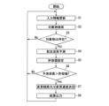
- FIG. 2 is a flow diagram showing processing in the arithmetic unit of FIG.
- FIG. 3 is a flow diagram showing the process of predicting the traveling wave height in FIG. 2.
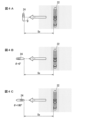
- FIG. 4 is a schematic diagram showing the relationship between the traveling direction of a sailing wave and the direction of another ship, for explaining the tolerance value setting process of FIG. 2.
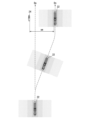
- FIG. 5 is a schematic diagram showing an example of the result of the process of determining the course to be changed or the speed to be changed in FIG. 2.
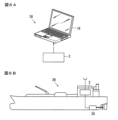
- FIG. 6A is an example of a traveling wave reduction support system using this support device
- FIG. 6B is an example of a ship equipped with this support device.
- FIG. 6A is an example of a traveling wave reduction support system using this support device
- FIG. 6B is an example of a ship equipped with this support device.
- FIG. 7 is a flow diagram showing another embodiment of the navigation wave height prediction process of FIG. 2.
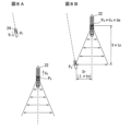
- 8A and 8B are schematic diagrams for explaining the process of calculating the traveling wave distance in FIG. 7.
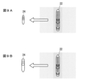
- FIG. 9 is a schematic diagram showing the relationship between traveling waves and the size of another ship, for explaining another embodiment of the allowable value setting process of FIG. 2.
- FIG. 10 is a schematic diagram showing an example of the result of the process of determining the course change or speed change in FIG. 2 in another embodiment.
- FIG. 11A is a flowchart showing still another embodiment of the process of determining the changed course or changed speed in FIG. 2, and
- FIG. 11B is a schematic diagram showing an example of the result of this process.
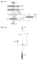
- FIG. 12A is a flowchart showing still another embodiment of the process of determining the course change or speed change of FIG. 2, and FIG. 12B is a schematic diagram for explaining this process.
- FIG. 13 is a schematic diagram for explaining still another embodiment of the process of determining the changed course or changed speed in FIG. 2.
- FIG. 1 is a block diagram showing a traveling wave reduction support device 2 (hereinafter referred to as support device 2) according to an embodiment.
- This support device 2 is mounted on a ship.
- This support device 2 is a device for reducing the influence of sailing waves emitted by a ship on other ships, structures installed in the ocean, and the like.
- the ship on which the present support device 2 is installed is referred to as "own ship.”
- Other vessels affected by the waves of the own vessel are referred to as “other vessels.”
- the other vessel may be sailing (including sailing, drifting, and anchored) or moored.
- Structures installed in the ocean that need to take into account the effects of waves generated by own ships are called “offshore structures.” Examples of marine structures include piers, aquaculture rafts, and equipment under construction.
- FIG. 1 A block diagram of the support device 2 is shown in FIG.
- This support device 2 includes an input interface 4, a memory 6, and an arithmetic unit 8.
- various devices that send information to the support device 2 are shown.
- the GNSS receiver 10 the gyro compass 13 , and the ship maneuvering device 15 send information about the own ship to the support device 2 .
- An AIS (Automatic Identification System) receiver 12 sends information about other ships to the support device 2 .
- the camera 16, LiDAR 14, and radar 14 send information about the surroundings of the ship to the support device 2.
- These devices are installed on board the ship.
- the input device 17 is used by the crew of the ship.
- the input device 17 is typically a keyboard or a touch panel.
- FIG. 1 also shows a display device 18 and an automatic driving device 20 that receive the results of the support device 2.
- the input interface 4 acquires information from the equipment shown in FIG.
- the information that each device can provide to the input interface 4 is as follows.
- (a) GNSS receiver 10 Information that the GNSS receiver 10 can provide to the input interface 4 includes the current position and true course of the ship.
- the true course is the direction in which the ship is actually moving. Your own vessel may not only move toward the bow, but may also be affected by tidal currents. Additionally, the own ship may move laterally due to side thrusters. The true course is the direction in which the ship is moving relative to the earth, including these effects.
- Gyro compass 13 Information that can be provided by the gyro compass 13 to the input interface 4 includes the heading direction of the own ship.
- Ship maneuvering device 15 includes an engine control device and a steering control device.
- Information that the engine control device can provide to the input interface 4 includes a set value of the engine rotation speed and its measured value. The approximate speed of your ship can be obtained from the engine rotation speed.
- Information that the steering control device can provide to the input interface 4 includes a steering angle setting value and its measured value. From the rudder angle, the approximate course direction of the ship can be obtained.
- the AIS receiver 12 provides the input interface 4 with information on other vessels.
- Information on other ships that can be obtained by the AIS receiver 12 includes the ship type, captain, width, position, heading, speed over the ground, navigational state, and turning speed of the other ship. The turning speed here is the speed at which the heading of the ship changes.
- the nautical state indicates whether the other vessel is at anchor, moored, maneuvering, sailing, or in a state in which the vessel is unable to operate.
- AIS transmitters are installed on board other ships or at relay facilities on land. The relay facility receives information from AIS transmitters mounted on other ships, and transmits this information from the AIS transmitter of the relay facility. Note that small ships may not be equipped with an AIS transmitter. In this case, there is no AIS transmitter that sends information about other vessels to the input interface 4.
- Camera 16 Information that the camera 16 can provide to the input interface 4 includes the type, direction (facing angle), size, and shape of other ships and marine structures. These can be obtained by analyzing captured images. Furthermore, by photographing the object from a plurality of different positions using a stereo camera or the like, the relative distance between the own ship and other ships or marine structures can be obtained. Furthermore, by obtaining the relative distance to other ships at predetermined time intervals, it is possible to obtain the relative speeds of the other ships and the own ship.
- cameras 16 include regular cameras 16 and infrared cameras 16. This allows the input interface 4 to obtain information on other ships and marine structures from the camera 16 not only during the day but also at night.
- LiDAR or radar 14 Information that the LiDAR 14 or the radar 14 can provide to the input interface 4 includes the relative distance between the own ship and other ships or marine structures. Furthermore, by obtaining the relative distance to other ships at predetermined time intervals, it is possible to obtain the relative speeds of the other ships and the own ship.
- the input interface 4 can obtain various parameters specified by the user from the input device 17. Examples of the parameters include the characteristic wave height and the allowable wave height of other ships or marine structures when calculating the predicted value of the cruising wave height, which will be described later.
- the input interface 4 acquires information from the devices (a) to (g) above, but this diagram is just an example. The input interface 4 does not need to acquire information from all the devices (a) to (g) above. Information may be acquired from some of the devices (a) to (g) above.
- the relative distance between the ship and other ships or marine structures is required.
- This distance can be obtained from LiDAR 14 or radar 14.
- This relative distance may be obtained from camera 16.
- the relative distance to another ship may be obtained from the position of the own ship obtained from the GNSS receiver 10 and the position of the other ship obtained from the AIS receiver 12.
- the relative distance to the marine structure may be obtained from the position of the ship obtained from the GNSS receiver 10 and the position of the marine structure obtained from the electronic chart. Relative distances may be obtained by combining these.
- AIS receiver 12 and electronic chart may not be necessary.
- the information acquired by the input interface 4 needs to include at least position information (absolute position or relative position with respect to the main ship) of another ship or marine structure.
- information on the shape (length or direction) of the other vessel is required.
- This shape information may be obtained from the camera 16 or from the AIS receiver 12. This shape information may be obtained by combining these.
- information on the shape of the other vessel is obtained from the camera 16.
- the devices from which the input interface 4 acquires information are not limited to the above (a) to (g).
- the input interface 4 may obtain information about its own ship and information about other ships or marine structures from other devices.
- the storage device 6 stores electronic charts.
- the computing unit 8 acquires electronic chart information from the memory 6.
- This electronic nautical chart includes information on marine structures.
- the information on the marine structure includes the position, size, shape, and permissible wave height of the marine structure.
- the allowable wave height is the maximum allowable wave height to ensure the safety of this offshore structure.
- the allowable wave height does not need to be included in the marine structure information.
- Electronic charts are updated as necessary via mobile communications or satellite communications.
- the calculator 8 predicts the wave height at the position of another ship or offshore structure of the traveling waves generated when the own ship navigates on the current course and speed. , it is determined whether the predicted wave height exceeds the allowable value. When the permissible value is exceeded, the calculator 8 determines the course to change or the speed to change in order to reduce the wave height.
- the arithmetic unit 8 is composed of a processor and a program for operating the processor. The program is stored in the storage device 6. A part or all of the arithmetic unit 8 may be composed of a dedicated circuit.
- FIG. 2 shows the processing flow of the arithmetic unit 8. As shown in FIG. 2, this processing flow includes steps S1 to S8.
- step 1 the computing unit 8 receives information from the input interface 4.
- the calculator 8 reads electronic chart information if it is written in the memory 8. Since the information from the input interface 4 is updated sequentially, the arithmetic unit 8 continuously updates the information from the input interface 4.
- the computing unit 8 searches for objects that may be affected by traveling waves from the information received from the input interface 4. For example, the computing unit 8 searches for other ships or marine structures from images from the camera 16 or from information from LiDAR 14 or radar 14 . The computing unit 8 may also search for marine structures located within a predetermined distance from the own ship based on the information of the electronic chart. Other vessels or marine structures that have been searched for are considered "objects" that may be affected by traveling waves. In this embodiment, when a plurality of other ships or marine structures exist, the other ship or marine structure closest to the own ship is determined as the target object. As another embodiment, other ships that are most susceptible to the effects of traveling waves may be targeted. For example, the smallest other vessel may be targeted. A plurality of other ships or offshore structures that may be affected by the traveling waves may also be targeted. In this case, this process is performed for each object, and an appropriate course change or change speed is selected from the results.
- step 3 the result of the search for the object in step 2 is determined.
- step S4 is executed, and when the target object does not exist, the process returns to step S1.
- step 4 the calculator 8 predicts the wave height of the traveling waves generated by the own ship at the position of the target object, another ship or marine structure.
- the wave height at the position of another ship or marine structure as a target is predicted using the shortest distance between the own ship and the target object measured in a direction perpendicular to the direction of travel of the own ship.
- FIG. 3 shows the processing flow in step 4.
- step 4 further includes the following steps 4-1) to 4-4).
- Step 4-1) Determining the distance to the target object
- the distance between the ship and the target object is determined from the information from the LiDAR 14 or the radar 14.
- the distance between the ship and the object may be identified from camera images taken from a plurality of different positions.
- position information of another ship is obtained from an AIS transmitter mounted on the other ship
- the distance between the own ship and the other ship may be specified from the position of the own ship and the position of the other ship.
- the target object is a marine structure identified from an electronic nautical chart, the distance may be determined from the position of the own vessel and the position of this marine structure.
- the traveling direction (relative traveling direction) of the own ship with respect to the target other ship or marine structure is specified. For example, by measuring the distance and direction of another ship with respect to the own ship twice at predetermined intervals using the LiDAR 14, the radar 14, or the camera 16, the relative traveling direction can be determined.
- the relative heading direction is determined from the heading direction of the own vessel and the true course of the other vessel obtained from the information of the own vessel's AIS receiver 12. Good too. Note that when the object is stationary, the traveling direction of the own vessel is the relative traveling direction.
- Step 4-3) Calculate the shortest distance between the object and your own ship Based on the distance between the object and your own ship and the relative direction of travel, the course of your own ship when it navigates on its current course and speed. The shortest distance Ss between the planned line and the object measured in the vertical direction is calculated.
- Step 4-4) Calculate the predicted value of the height of the traveling wave at the position of the target object.
- H0 is the characteristic wave height of the traveling wave.
- the characteristic wave height H0 is the maximum wave height observed at a distance of 100 m from the track center line when the own vessel is traveling at full cruising speed.
- Vk is the full cruising speed of the host vessel.
- the characteristic wave height H0 and the full load cruising speed Vk are obtained in advance in the own ship. These are stored in the memory 6 or input by the user from the input device 17.
- the calculator 8 calculates the predicted value HM of the traveling wave height at the position of the object by setting the distance S to the shortest distance Ss in the above equation (1).
- the wave height (tolerable value) that the object can tolerate is set.
- the method for setting the allowable value differs depending on whether the object is another ship or another marine structure.
- a predetermined allowable wave height value determined in advance is set as the allowable value. If the target object is a marine structure acquired from the memory 6 and the allowable wave height is stored in the memory 6, the allowable wave height is set as the allowable value.
- the permissible wave height is input from the input device 17, the permissible wave height is set as the permissible value.
- the allowable value is set based on the orientation of the other ship with respect to the traveling direction of the traveling waves. As an example, the allowable value is set in steps 5-1) to 5-3) below.
- Step 5-1) Identifying the orientation of other ships
- the computing unit 8 identifies the orientation of other ships (for example, the direction in which the front and back directions are facing) from the image of the camera 16.
- the direction of travel of the other ship may be specified and this may be set as the forward/backward direction.
- the direction of the other vessel may be specified from the heading direction of the other vessel obtained from the information of the AIS receiver 12 of the own vessel.
- the computer 8 determines that the distance between the other ship and the own ship is the shortest distance Ss, assuming that the own ship is navigating at the current speed and the current course. Identify the direction of other ships relative to the traveling direction of the sailing waves when This situation is shown in FIG. In FIG. 4, the hatches on both sides of the host vessel 22 represent traveling waves. The darker the hatch, the higher the wave height of the traveling waves. The arrow represents the direction of travel of the traveling wave. It is assumed that the traveling waves travel in a direction perpendicular to the traveling direction of the host vessel 22.
- the computing unit 8 identifies the direction of the other ship 24 with respect to the traveling direction of the traveling wave from the direction of the other ship 24 and the traveling direction of the traveling wave.
- FIG. 4A shows an example in which the traveling direction of the sailing waves and the longitudinal direction of the other vessel 24 are perpendicular.
- 4B and 4C show an example in which the traveling direction of the sailing waves and the longitudinal direction of the other vessel 24 are parallel.
- Step 5-3) Setting of permissible value
- the calculator 8 sets a permissible value corresponding to the orientation of the other vessel 24 with respect to the traveling direction of the traveling wave.
- the symbol ⁇ represents the angle between the traveling direction of the sailing wave and the longitudinal direction of the other vessel 24.
- the allowable value is set small.
- the angle ⁇ when receiving a traveling wave from the front is 0° and the angle ⁇ when receiving a traveling wave from the rear is 180°, in this embodiment, the angle ⁇ is changed from 0° to 90°.
- the allowable value is set continuously smaller, and as the angle ⁇ approaches 180°, the allowable value is set continuously larger.
- the allowable value may be set smaller in steps.
- the allowable value may be set to be larger in steps.
- the allowable value when receiving a traveling wave from the front (FIG. 4B) is set larger than the allowable value when receiving a traveling wave from the rear (FIG. 4C). That is, the allowable value when the angle ⁇ is 0° is set to a larger value than the allowable value when the angle ⁇ is 180°.
- step 6 the calculator 8 compares the predicted value HM of the traveling wave height calculated in step S4 with the allowable value set in step S5. If the predicted value HM exceeds the allowable value, step S7 is executed. If the predicted value HM is less than or equal to the allowable value, the process returns to step S1.
- step 7 the course change or change speed is determined in order to reduce the traveling wave height at the position of the object.
- step 8 the course change or change speed to be output is determined.
- the traveling wave height is reduced by changing the course while maintaining the speed. That is, in this embodiment, only a course change is determined.
- Figure 5 shows an example of a course change.
- a broken line Do represents the current planned course.
- the changed course can be determined, for example, by the following steps.
- Step 7-1) Calculation of permissible distance from other ships 24 Calculating the minimum necessary distance ( Tolerance distance). This can be obtained by calculating the distance S such that the traveling wave height HM becomes an allowable value in the above-mentioned equation (1).
- the symbol sm represents the allowable distance.
- the calculator 8 determines a course in which the minimum distance between the own vessel 22 and the other vessel 24 is the above-mentioned allowable distance sm.
- the broken line Dn in FIG. 5 is an example of this course.
- the computing unit 8 determines this course as the changed course to be output.
- the computing unit 8 predicts the course when the course is changed to the maximum extent possible, and determines this as the changed course to be output.
- step 8 the determination result in step 7 is output.
- information on the changed course is output.
- the results can be output as either data for the display device 18 or data for the automatic driving device 20.
- the data for the display device 18 also includes information on the progress of the sailing waves and the wave height of the sailing waves.
- FIG. 6 shows an application example of the support device 2.
- FIG. 6A shows a traveling wave reduction support system 26 that includes the support device 2 and the display device 18.
- the display device 18 displays information on the changed course or changed speed output by the support device 2.
- the display device 18 may further display information on the progress of the sailing waves and the wave height of the sailing waves.
- FIG. 6B shows a ship 28 that includes the present support device 2 and the automatic driving device 20.
- the automatic driving device 20 performs automatic driving according to the changed course or changed speed output by the support device 2.
- the support device 2 of this embodiment predicts the wave height of the traveling waves generated by the own ship 22 at the position of another ship 24 or a marine structure, and determines a course change when this wave height exceeds a permissible value. . By navigating along this changed course, the own vessel 22 can lower the wave height of the traveling waves at the position of the other vessel 24 or the marine structure. With this support device 2, it is possible to suppress the influence of the traveling waves of the own ship 22 on other ships 24 or marine structures.
- a course change is determined not only for other ships 24 on the voyage, but also for other ships 24 at moorings and marine structures, so as to reduce the influence of sailing waves.
- this support device 2 it is possible to suppress the influence of traveling waves on other moored vessels 24 and marine structures.
- the support device 2 identifies the orientation of the other vessel 24 with respect to the traveling direction of the sailing waves, and sets a tolerance value corresponding to this orientation.
- the influence of the sailing waves differs depending on the orientation of the other vessel 24 with respect to the traveling direction of the sailing waves.
- the present support device 2 by setting a permissible value corresponding to this direction, it is possible to more effectively suppress the influence of the cruising waves on other ships 24.
- the allowable value is set smaller than when they are parallel.
- the traveling wave is a transverse wave with respect to the other vessel 24
- the influence on the other vessel 24 is greater than when it is a longitudinal wave.
- the traveling direction of the traveling wave and the longitudinal direction of the other vessel 24 are perpendicular, by making the tolerance smaller than when they are parallel, even if the traveling wave becomes a transverse wave, other than the traveling wave The influence on the ship 24 can be suppressed.
- the allowable value is set smaller continuously or stepwise.
- the influence of the traveling waves becomes larger as the angle ⁇ approaches 90°. By doing so, the influence on the ship 24 other than the traveling waves can be suppressed.
- the allowable value when the other vessel 24 receives the sailing waves from behind is set smaller than the allowable value when the other vessel 24 receives the sailing waves from the front.
- the influence of the traveling wave is greater than when it receives a traveling wave from the front.
- the support device 2 can output information about the changed course as data for the display device 18. Furthermore, the present support device 2 can also output information for displaying the progress of the traveling waves and the height of the traveling waves as data for the display device 18. The crew of the own ship 22 can check this information on the display screen. This contributes to safe driving by the crew, taking into account the influence of the cruising waves on the ship 24 or marine structures.
- the support device 2 can output information about the changed course as data for the automatic driving device 20.
- safe automatic operation is realized in which the influence on the ship 24 or marine structures other than the cruising waves is suppressed.
- step 4 the computing unit 8 predicts the wave height of the traveling wave generated by the own vessel 22 at the position of the object.
- the wave height of the traveling wave at the position where the traveling wave of the own ship 22 is predicted to come into contact with the other ship 24 is predicted as the wave height at the position of the other ship 24 that is the object.
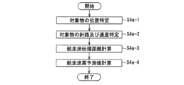
- step 4 shows the processing flow in step 4a.
- step 4 further includes the following steps 4a-1) to 4a-4).
- Step 4a-1) Identifying the position of the object From the information of the LiDAR 14 or the radar 14, the position P 1 (x 1 , y 1 ) of the object is specified.
- the position P1 of the object may be identified from camera images taken from a plurality of different positions.
- the position P1 may be specified from the information from the AIS transmitter. Note that the coordinate axes representing this position P1 may be determined appropriately.
- the forward/reverse direction of the own ship 22 may be set as the x-axis, and the lateral direction may be set as the y-axis.
- the forward and backward movement direction of the own ship 22 is taken as the x-axis.
- the speed vector v 0 representing the course and speed of the own ship 22 is expressed by the following equation. It is assumed that the traveling waves travel perpendicularly to the course of the host vessel 22. Therefore, the traveling wave travels parallel to the y-axis.
- a speed vector v1 representing the course and speed of the target other vessel 24 is identified.
- V 1x is the aforementioned velocity component in the x-axis direction
- V 1y is the aforementioned velocity component in the x-axis direction.
- a speed vector v 1 is obtained from this information and a speed vector v 0 representing the course and speed of the host vessel 22.
- the velocity vector v 1 may be calculated from this AIS information.
- Step 4a-3 Calculation of the propagation distance of a traveling wave when contacting another vessel 24
- the position P 0 and velocity vector v 0 of the own vessel 22 and the position P 1 and velocity vector v of the other vessel 24 are calculated. 1 , assuming that the own ship 22 and the other ship 24 navigate at the same speed and course, regarding the traveling waves that come into contact with the other ship 24, the navigation time from the generation of the traveling wave until contact with the other ship 24 is A traveling wave propagation distance Sr (cruising wave propagation distance Sr) is calculated.
- Sr cruising wave propagation distance Sr
- FIG. 8A is an example in which the current own ship 22 and other ships 24 are shown.
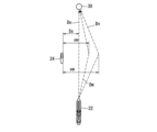
- FIG. 8B shows a diagram when the traveling waves of the own ship 22 come into contact with the other ship 24, assuming that both the own ship 22 and the other ship 24 are traveling at the current speed and course. As shown in FIG. 8B, the traveling waves spread behind the host vessel 22 at an angle with respect to the traveling direction. This traveling wave and the other vessel 24 are in contact at position Pq .
- the position P q1 of the other vessel 24 is is the following equation (4). Since the traveling wave and the other vessel 24 are in contact at position Pq after time tm seconds, becomes. If we rewrite this using equations (3) and (4) above, we get becomes.
- Step 4a-4) Calculate the predicted value of the traveling wave height at the target object position In this step, similarly to step 4-4) above, using equation (1), the traveling wave height H is predicted.
- the height H is calculated by setting the distance S to the above-mentioned traveling wave propagation distance Sr in equation (1).
- the traveling wave of the own ship 22 when it comes into contact with the other ship 24 is determined.
- the propagation distance of the traveling wave from generation to contact with another vessel 24 is predicted.
- the wave height at the position of the other vessel 24 is predicted.
- the “allowable value" shown in FIG. Processing based on the traveling wave propagation distance Sr is also adopted in the steps of ⁇ Setting'' and ⁇ Determining the changed route or changed speed.'' For example, in step 5-2 described above, the computing unit 8 calculates the traveling wave when the own ship 22 is traveling at the current speed and the current course, and when the other ship 24 and the own ship 22 are at the shortest distance Ss.
- the process of ⁇ specifying the direction of the other vessel 24 with respect to the direction of travel of the own vessel 24'' is performed by the computing unit 8, assuming that the own vessel 22 is navigating at the current speed and the current course, and that the traveling waves of the own vessel 22 are the same as those of the other vessel 24.
- the direction of the other vessel 24 with respect to the traveling direction of the sailing waves at the time of contact is specified.
- ⁇ The computing unit 8 calculates a course in which the minimum distance between the own vessel 22 and the other vessel 24 is the above-mentioned allowable distance sm'' "Find a course in which the traveling wave propagation distance Sr when the traveling waves come into contact with the other vessel 24 is the above-mentioned allowable distance sm.”
- step 7-2 "Even if the course is changed to the maximum extent possible, the minimum distance between the own ship 22 and the other ship 24 may not be the allowable distance sm. In this case, the calculator 8 changes the course as much as possible.
- the process of ⁇ predicting the course if the ship 22 changes its course and determining this as the changed course to be output'' means that ⁇ Even if the course is changed to the maximum extent, the waves of the own ship 22 will come into contact with the other ship 24. In some cases, the current traveling wave propagation distance Sr cannot be set to the allowable distance sm. In this case, the computing unit 8 predicts the course when the course is changed to the maximum extent possible, and determines this as the changed course to be output. will be changed.
- step 5 includes the following steps 5a-1) and 5a-2).
- the computing unit 8 identifies the length of the other vessel 24 from the image from the camera 16 and the information from the LiDAR 14 or the radar 14.
- the calculator 8 calculates the length of the other ship 24 from the length and direction of the other ship 24 in the image of the camera 16 and the distance between the own ship 22 and the other ship 24 obtained from the LiDAR 14 or the radar 14. do.
- the direction and length of the other vessel 24 may be specified from camera images taken from a plurality of different positions.
- the length of the other ship 24 may be specified from the information of the AIS receiver 12 of the own ship that received this AIS signal.
- the calculator 8 sets a tolerance value corresponding to the length of the other vessel 24. This situation is shown in FIG.
- the length of the other vessel 24 in FIG. 9B is shorter than the length of the other vessel 24 in FIG. 9A.
- the tolerance value is set smaller than in the case of FIG. 9A.
- the allowable value is set to a continuously smaller value as the length of the other vessel 24 becomes shorter.
- the allowable value may be set to a smaller value in stages as the length of the other vessel 24 becomes shorter.
- the allowable value is set to a smaller value continuously or stepwise.
- Small vessels 24 are susceptible to the effects of sailing waves. By setting the allowable value in this manner, the influence of the traveling waves is suppressed even on other small vessels 24.
- step 5 of step 5 of FIG. 2 the calculator 8 sets the tolerance value based on both the direction and length of the other vessel 24.
- step 5 includes the following steps 5b-1) to 5b-4).
- Step 5b-1) Identification of the direction of the other vessel 24
- Step 5b-2) Identification of the direction of the other vessel 24 with respect to the traveling direction of the sailing waves
- Step 5b-3) Identification of the length of the other vessel 24
- Step 5b-1) and step 5b-2) are the same as step 5-1) and step 5-2) described above, respectively.
- Step 5b-3) is the same as step 5a-1) described above.
- step 5b-4) as the angle ⁇ between the traveling direction of the sailing wave and the longitudinal direction of the other vessel 24 approaches 0° to 90°, and as the length of the other vessel 24 becomes shorter, the allowable value increases. , are set smaller continuously or stepwise.
- the tolerance value for the other vessel 24 is set to a predetermined value.
- the arithmetic unit 8 reads this value from the storage device 6, for example, and sets it as an allowable value.
- the calculator 8 sets, for example, the value input from the input device 17 as an allowable value.
- step 7 in FIG. 2 when the target object is another vessel 24, the speed is changed while the current course is maintained in order to reduce the height of the traveling waves at the position of the target object. That is, in this embodiment, only the changing speed to be output is determined.
- Figure 10 shows an example of reducing the cruising wave height by changing the speed.
- a broken line Do represents the current planned course.
- the own ship 22 is decelerating to the changed speed.
- the width of the hatches on both sides of the own vessel 22 gradually becomes smaller as the own vessel 22 advances. This indicates that the height of the traveling waves gradually decreases as the own ship 22 decelerates.
- the change speed is determined, for example, by the following steps.
- Step 7a-1) Calculation of target speed
- the calculator 8 calculates the upper limit value of the speed to keep the cruising wave height below the allowable value when the own ship 22 moves on the current course. This calculation uses the shortest distance Ss (see FIG. 10) between the own ship 22 and the object obtained in step 4-3).
- the upper limit value of the speed can be obtained by calculating the speed VK such that the traveling wave height HM becomes an allowable value, with the distance S set to the shortest distance Ss in the above-mentioned equation (1).
- the speed thus obtained is called the upper limit speed VM.
- the computing unit 8 determines the above-mentioned upper limit speed VM as the changing speed to be output. However, since inertia acts on the own vessel 22 while it is sailing, there may be cases where it cannot decelerate to the upper limit speed VM even if it decelerates to the maximum. In this case, the calculator 8 sets the predicted value of the speed at the time of maximum deceleration as the changed speed.
- the support device 2 predicts the wave height of the traveling waves generated by the own ship 22 at the position of the other ship 24 or the marine structure, and when this wave height exceeds a permissible value, changes the speed. demand. By navigating at this changed speed, the own vessel 22 can lower the wave height of the traveling waves at the position of the other vessel 24 or the marine structure. With this support device 2, it is possible to suppress the influence of the traveling waves of the own ship 22 on other ships 24 or marine structures.
- step 7a-1 the upper limit value of the speed is obtained by calculating the speed VK such that the traveling wave height HM becomes an allowable value in the above-mentioned equation (1), where the distance S is the traveling wave propagation distance Sr.
- step 7 of FIG. 2 at least one of the course or the speed is changed to reduce the traveling wave height at the target location.
- this course is determined as the changed course. If the wave height cannot be reduced to below the allowable value by changing the course alone, the changed course and speed are determined so that the wave height can be reduced as much as possible by changing the course, and the wave height can be further reduced by changing the speed.
- FIG. 11A shows the flow of this process.
- FIG. 11B shows an example of the results of this process. As shown in FIG. 11A, this process includes steps 7b-1) to 7b-5).
- Step 7b-1) Calculation of tolerance distance This step is the same as step 7-1) above. That is, the calculator 8 calculates the minimum necessary distance (permissible distance sm) for making the cruising wave height below the permissible value when the own ship 22 travels at the current speed.
- Step 7b-2) Determine whether the changing course can reduce the sailing wave height below the allowable value.
- the calculator 8 determines the minimum distance between the own ship 22 and the other ship 24 when the course is changed to the maximum extent possible. By determining whether or not the distance can be made equal to or greater than the allowable distance sm, it is determined whether or not the cruising wave height can be made less than or equal to the allowable value only by changing the course. If it is determined that this is not possible, step 7b-3 is executed. If it is determined that it is possible, step 7b-5) is executed.
- Step 7b-3 Determination of the first changed course
- the calculator 8 determines that the course (first course) in which the own ship 22 passes as far as possible from other ships 24 is the changed course to be output. It is determined.
- the dashed arrow Dm in FIG. 11B represents an example of the determined changed course. As shown in FIG. 11B, in the changed course Dm, the distance between the own ship 22 and the other ship 24 is smaller than the allowable distance sm.
- Step 7b-4) Determination of changing speed
- the computing unit 8 determines the changing speed for further reducing the sailing wave height.
- the same process as step 7a-1) and step 7a-2) described above is executed assuming that the own ship 22 is navigating along the above-mentioned course Dm.
- the width of the hatches on both sides of the own vessel 22 becomes narrower as the own vessel 22 advances. This indicates that the own ship 22 is decelerating to the changed speed.
- Step 7b-5 Determination of the second course to be changed
- the computing unit 8 determines that the course (second course) in which the minimum distance between the own vessel 22 and the other vessel 24 is the above-mentioned allowable distance sm is This is determined as the changed course to be output.
- the wave height is reduced as much as possible by changing the course, and the wave height is further reduced by reducing the speed. is required.
- the own ship 22 can lower the wave height of the traveling waves at the position of the other ship 24 or the marine structure. In this embodiment, it is possible to reduce the influence of traveling waves on other ships 24 or marine structures while suppressing a reduction in speed as much as possible.
- step 7b-5 the traveling wave propagation distance Sr when the traveling waves of the own ship 22 come into contact with the other ship 24 is used instead of "the minimum distance between the own ship 22 and the other ship 24".
- step 7 of FIG. 2 at least one of the course or the speed is changed to reduce the traveling wave height at the target location.
- this speed is set as the changing speed. If the wave height cannot be reduced to below the allowable value only by changing the speed, the changed course and speed are determined so that the wave height can be reduced to the maximum extent possible by changing the speed and further reduced by changing the course.
- the own ship 22 can lower the wave height of the traveling waves at the position of the other ship 24 or the marine structure. In this embodiment, it is possible to suppress changes in course as much as possible while reducing the influence of traveling waves on other ships 24 or marine structures.
- the fastest expected arrival time is when the sailing wave height is reduced to below the reference value only by changing the course, and when the sailing wave height is reduced below the reference value only by changing the speed.
- the expected arrival time is determined so as to realize the earlier one.
- FIG. 12A shows the flow of this process.
- FIG. 12B is a schematic diagram illustrating this process. As shown in FIG. 12A, this process includes steps 7c-1) to 7c-5).
- Step 7c-1) Calculation of the first arrival time Ta1
- the calculator 8 calculates the fastest way to the "destination point 30" when the wave height of the sailing waves is reduced to the permissible value or less by only changing the course.
- a predicted arrival time (first arrival time Ta1) is calculated.
- the fastest course is the course in which the minimum distance between the own ship 22 and the other ship 24 is the above-mentioned allowable distance sm (arrow Dn in FIG. 12B). ).
- the course Dn is a course that returns to the current planned course (arrow Do in FIG.
- the calculator 8 calculates the "elapsed time” by dividing the distance to the destination point 30 on the course Dn by the current speed, and adds this to the current time to calculate the first arrival time Ta1.
- the computing unit 8 calculates the fastest predicted arrival time at the destination point 30 when the wave height of the traveling wave is reduced to a permissible value or less by only changing the speed.
- the time (second arrival time Ta2) is calculated.
- the upper limit speed VM is calculated so that the cruising wave height HM becomes an allowable value.
- the calculator 8 estimates the average speed Va from the current position to the destination point 30.
- Va may be simply the average speed value of the current speed and the upper limit speed VM.
- the calculator 8 calculates the "elapsed time" by dividing the distance to the destination point 30 on the planned course Do by the average speed Va. By adding this to the current time, the second arrival time Ta2 is obtained.
- Step 7c-3) Comparison of First Arrival Time Ta1 and Second Arrival Time Ta2
- the computing unit 8 compares the first arrival time Ta1 and the second arrival time Ta2. If the first arrival time Ta1 is equal to or earlier than the second arrival time Ta2, step 7c-4) is performed. If the first arrival time Ta1 is later than the second arrival time Ta2, step 7c-5) is executed.
- Step 7c-4) Determination of course change
- the course with the fastest arrival time (course Dn in Fig. 12B) when the wave height of the traveling waves is kept below the allowable value by only changing the course is determined as the output. This is determined as the changed course.
- Step 7c-5) Determining the changed speed to be output In this step, when the wave height of the traveling wave is made below the allowable value only by changing the speed, the speed at which the arrival time is the fastest (upper limit speed VM) is output. determined as the rate of change.
- the support device 2 determines the arrival time when the sailing wave height is reduced to below the reference value only by changing the course, and the arrival time when the sailing wave height is reduced below the reference value only by changing the speed. Either the changed course or the changed speed is determined so as to realize the faster of the above. By navigating according to this changed course or changed speed, the own ship 22 can reduce the wave height of the traveling waves at the position of the other ship 24 or the marine structure while reducing the delay in arrival time.
- the traveling wave propagation distance Sr when the traveling waves of the own ship 22 come into contact with the other ship 24 is used instead of "the minimum distance to the ship 24."
- step 7 in FIG. In addition to "When the wave height of the traveling wave is below the allowable value due to a combination of course change and speed change", the arrival time at destination point 30 will be the earliest. Thus, the changed course or changed speed is determined.
- FIG. 13 is a diagram explaining this process.
- arrow Do represents the planned course similarly to FIG. 12B. This is the course when the sailing wave height is brought to an acceptable value only by changing the speed.
- the arrow Dn represents the course when the sailing wave height is brought to the permissible value only by changing the course.
- Arrow Dm represents a course when the wave height of the traveling wave is set to an allowable value by a combination of a change in course and a change in speed. The speed at this time is faster than when sailing on the course Do, and slower than when sailing on the course Dn.
- the calculator 8 takes, for example, the minimum value of the distance between the own ship 22 and the other ships 24 on the course Dm as xm (Ss ⁇ xm ⁇ sm) (see FIG. 13), and calculates the distance xm at which the arrival time Tx is the earliest. do. From the course and speed at this time, the changed course or changed speed is determined.
- the changed course or changed speed is determined, including a combination of changing the course and changing the speed, so as to make the arrival time the earliest while keeping the cruising wave height to an acceptable value.
- the own ship 22 can reduce the wave height of the traveling waves at the position of the other ship 24 or the marine structure while reducing the delay in arrival time.
- the traveling wave propagation distance Sr when the traveling waves of the own ship 22 come into contact with the other ship 24 is used instead of "the minimum distance to the ship 24."
- a course change or a change speed is determined such that fuel consumption is minimized. For example, this can be achieved by obtaining data on the relationship between speed changes and fuel efficiency in advance.
- this support device can reduce the influence of sailing waves on other ships and marine structures. From this, the superiority of this support device is clear.
- the functions of the computing unit disclosed herein may be implemented using general purpose processors, special purpose processors, integrated circuits, ASICs (Application Specific Integrated Circuits), conventional circuits, and/or configured or programmed to perform the disclosed functions. combinations thereof, or using processing circuitry.
- Processors are considered processing circuits or circuits because they include transistors and other circuits.
- a circuit, unit, or means is hardware that performs the recited functions or is hardware that is programmed to perform the recited functions.
- the hardware may be the hardware disclosed herein or other known hardware that is programmed or configured to perform the recited functions. If the hardware is a processor, which is considered a type of circuit, the circuit, means or unit is a combination of hardware and software, the software being used for the configuration of the hardware and/or the processor.
- a navigation wave reduction support device installed on a ship, an input interface for acquiring information about the ship and information about other ships or marine structures around the ship; a computing unit into which the information is input from the input interface; Equipped with The arithmetic unit, based on the input information, predicting the wave height at the position of the other ship or the marine structure of the traveling waves generated when the ship navigates at the current course and speed; Determining whether the predicted wave height exceeds a tolerance value, determining the changed course or changed speed when the tolerance value is exceeded, and outputs information on the changed course or changed speed; Traveling wave reduction support device.
- the wave height of the traveling waves at the position of other ships or marine structures can be lowered, and the influence of the own ship's own traveling waves on other ships or marine structures can be suppressed.
- the information input to the computing unit includes information for obtaining the position, course, and speed of the other vessel;
- the computing unit calculates the wave height at a position where the traveling waves of the ship and the other ship come into contact based on the position, course, and speed of the ship and the position, course, and speed of the other ship.
- the traveling wave reduction support device according to item 3, which predicts.
- the information input to the calculator includes information for obtaining the direction of the other ship,
- the arithmetic unit is identifying the direction of the other vessel with respect to the traveling direction of the sailing waves generated by the vessel based on the information for determining the direction;
- the traveling wave reduction support device according to item 3, further comprising: setting the permissible value corresponding to the orientation.
- the information input to the calculator includes information for obtaining the size of the other ship,
- the arithmetic unit is identifying the length of the other vessel based on information for obtaining the size of the other vessel;
- the traveling wave reduction support device according to any one of items 3 to 6, further comprising: setting the allowable value corresponding to the length.
- the computing unit Determining whether it is possible to reduce the wave height of the sailing wave to the permissible value or less by simply changing the course; When it is determined that it is possible, find the changed course that makes the wave height less than or equal to the allowable value by only changing the course, If it is determined that this is not possible, then calculate the changed course and the changed speed by reducing the wave height as much as possible by changing the course and further reducing the wave height by changing the speed. Sailing wave reduction support device described.
- the wave height of the sailing wave can be lowered by changing the speed at the same time. It is possible to reduce the influence of traveling waves on other vessels or marine structures while suppressing the reduction in speed as much as possible.
- the first arrival time is the fastest predicted arrival time at the destination point when the wave height of the sailing wave is reduced to the permissible value or less by only changing the course;
- the fastest predicted arrival time to the destination point is set as the second arrival time when the wave height of the traveling wave is reduced to the permissible value or less by only changing the speed,
- the computing unit calculates the first arrival time and calculating the second arrival time;
- the course that realizes the first arrival time is set as the changed course,
- the traveling wave reduction support device according to any one of items 1 to 8, wherein when the second arrival time is earlier than the first arrival time, the changing speed is a speed that realizes the second arrival time.
- the computing unit When determining the changed course or changed speed, the computing unit When the wave height of the sailing waves is reduced to below the permissible value only by changing the course, when the wave height of the sailing wave is reduced below the permissible value only by changing the speed, and when changing the course and speed When the wave height of the sailing wave is made to be equal to or less than the allowable value in combination, the course or speed, or a combination thereof, that results in the earliest arrival time at the destination point is set as the changed course or the changed speed;
- the traveling wave reduction support device according to any one of items 1 to 8.
- a course change or a speed change can be used to reduce the delay in arrival time and to improve navigation at the location of other vessels or offshore structures.
- the height of waves can be lowered.
- a traveling wave reduction support system comprising the traveling wave reduction support device according to item 12 and a display device that displays information on the changed course or the changed speed.
- a ship comprising: the traveling wave reduction support device according to item 13; and an automatic driving device that automatically operates based on information about the changed course or the changed speed.
- a navigation wave reduction support method used during navigation of a ship comprising: Based on information on the vessel and information on other vessels or marine structures around the vessel, predicting the wave height at the position of the other ship or the marine structure of the traveling waves generated when the ship navigates at the current course and speed; Determining whether the predicted wave height exceeds a tolerance value, determining the changed course or changed speed when the tolerance value is exceeded, and outputs information on the changed course or changed speed; Navigation wave reduction support method.
- Airborne wave reduction support device 4 Airborne wave reduction support device 4
- Input interface 6 Memory device 8
- Arithmetic unit 10 ... GNSS receiver 12
- AIS transmission equipment 13 ... Gyro compass 14.
- LiDAR, radar 15 ... Ship maneuvering device 16 ... Camera 17
- Input device 18 ... Display device 20
- Automatic operation device 22 ... Own ship 24
- Other ship 26 ... ⁇ Travelling wave reduction support system 28
- Ship 30 ...Destination point
Landscapes
- Engineering & Computer Science (AREA)
- Chemical & Material Sciences (AREA)
- Combustion & Propulsion (AREA)
- Mechanical Engineering (AREA)
- Ocean & Marine Engineering (AREA)
- Radar, Positioning & Navigation (AREA)
- Remote Sensing (AREA)
- Traffic Control Systems (AREA)
- Navigation (AREA)
Abstract
本装置は、船舶に搭載される航走波低減支援装置2である。本装置は、前記船舶の情報、及び前記船舶の周囲の他船舶24又は海洋構造物の情報を取得する入力インターフェース4と、前記入力インターフェース4又は前記憶器6から前記情報が入力される演算器8と、を備える。前記演算器8は、前記入力された情報に基づき、前記船舶が現行針路及び現行速度で航行したときに発生させる航走波の、前記他船舶24又は前記海洋構造物の位置での波高を予測し、前記予測した波高が許容値を超えるか否かを判断し、前記許容値を超えるときに変更針路又は変更速度を求め、前記変更針路又は変更速度の情報を出力する。
Description
本開示は、航走波低減支援装置、プログラム及び方法に関する。
船舶が航行した際に生じる航走波は、小型船舶の転覆、係留中の船舶の破損等の事故の要因となりうる。近年、大型船舶の増加や船舶の高速化により、航走波の影響は増す傾向にある。航走波の影響による事故を防止する装置への要求が、大きくなっている。例えば特開2016-55772公報には、他船が発生させた航走波を検知して、グラフィカルに表示する装置が開示されている。これにより、ユーザーが航走波の影響を低減するための行動をとることを、可能としている。
航走波を検知するシステムが他船が発生させた航走波を検知しても、乗員の不注意等で、十分な回避行動をとれない場合がある。また係留中の船舶や海洋中に設けられた構造物は、航走波を回避することはできない。航走波を発生させる側の船舶において、航走波が他の船舶及び構造物に及ぼす影響を低減させることが重要となる。
本発明者の意図するところは、航走波が他船舶及び海洋中の構造物に及ぼす影響を低減させることを可能にした、航走波低減支援装置、プログラム及び方法の提供にある。
本装置は、船舶に搭載される航走波低減支援装置である。本装置は、前記船舶の情報及び前記船舶の周囲の他船舶又は海洋構造物の情報を取得する入力インターフェースと、前記入力インターフェースからの前記情報が入力される演算器と、を備える。前記演算器は、前記入力された情報に基づき、前記船舶が現行針路及び現行速度で航行したときに発生させる航走波の、前記他船舶又は前記海洋構造物の位置での波高を予測し、前記予測した波高が許容値を超えるか否かを判断し、前記許容値を超えるときに変更針路又は変更速度を求め、前記変更針路又は変更速度の情報を出力する。
本プログラムは、船舶に搭載されたプロセッサを動作させるプログラムである。本プログラムは、前記船舶の情報、及び前記船舶の周囲の他船舶又は海洋構造物の情報に基づき、前記船舶が現行針路及び現行速度で航行したときに発生させる航走波の、前記他船舶又は前記海洋構造物の位置での波高を予測する処理と、前記予測した波高が許容値を超えるか否かを判断する処理と、前記許容値を超えるときに変更針路又は変更速度を求め前記変更針路又は変更速度の情報を出力する処理と、を前記プロセッサに実行させる。
本方法は、船舶の航行の際に使用される航走波低減支援方法である。本方法は、前記船舶の情報、及び前記船舶の周囲の他船舶又は海洋構造物の情報に基づき、前記船舶が現行針路及び現行速度で航行したときに発生させる航走波の、前記他船舶又は前記海洋構造物の位置での波高を予測し、前記予測した波高が許容値を超えるか否かを判断し、前記許容値を超えるときに変更針路又は変更速度を求め、前記変更針路又は変更速度の情報を出力する。
本航走波低減支援装置は、船舶が発生させる航走波の、他船舶又は海洋構造物の位置での波高を予測し、この波高が許容値を超える場合に、変更針路又は変更速度を求めて、この情報出力する。これにより、航走波の他船舶又は海洋構造物へ影響を抑えることができる。
以下、適宜図面が参照されつつ、好ましい実施形態が詳細に説明される。
図1は、一実施形態に係る航走波低減支援装置2(以下支援装置2と称される)が示されたブロック図である。この支援装置2は、船舶に搭載される。この支援装置2は、船舶が出す航走波の、他の船舶、海洋に設置された構造物等への影響を低減するための装置である。本明細書では、本支援装置2が搭載された船舶は、「自船舶」と称される。自船舶の航走波の影響を受ける他の船舶は、「他船舶」と称される。他船舶は、航海中(航行中、漂泊中及び錨泊中を含む)であってもよく、係留中であってもよい。自船舶の航走波の影響を考慮する必要がある海洋に設置された構造物は、「海洋構造物」と称される。海洋構造物の例として、桟橋、養殖用筏、建設中の設備が挙げられる。
図1に、支援装置2のブロック図が示されている。この支援装置2は、入力インターフェース4、記憶器6及び演算器8を備える。図1には、支援装置2に情報を送る種々の機器が示されている。これらのうち、GNSS受信器10、ジャイロコンパス13及び操船装置15は、自船舶の情報を支援装置2に送る。AIS(Automatic Identification System)受信器12は、他船舶の情報を支援装置2に送る。カメラ16、LiDAR14及びレーダー14は、自船舶の周囲情報を、支援装置2に送る。これらの機器は、自船舶に搭載されている。入力器17は、自船舶の乗員が使用する。入力器17は、典型的にはキーボード又はタッチパネルである。図1には、本支援装置2の結果を受け取る、表示装置18及び自動運転装置20も示されている。
入力インターフェース4は、図1に示された機器から情報を取得する。各機器が入力インターフェース4に提供可能な情報は、以下のとおりである。
(a)GNSS受信器10
GNSS受信器10が入力インターフェース4に提供可能な情報として、自船舶の現在位置及び真針路が挙げられる。ここで真針路とは、自船舶が実際に移動している方向である。自船舶は、船首方向に移動するだけではなく、潮流の影響を受けることがある。また自船舶は、サイドスラスタにより横方向に移動することがある。これらの影響も含め、地球に対して自船舶が移動している方向が、真針路である。
GNSS受信器10が入力インターフェース4に提供可能な情報として、自船舶の現在位置及び真針路が挙げられる。ここで真針路とは、自船舶が実際に移動している方向である。自船舶は、船首方向に移動するだけではなく、潮流の影響を受けることがある。また自船舶は、サイドスラスタにより横方向に移動することがある。これらの影響も含め、地球に対して自船舶が移動している方向が、真針路である。
(b)ジャイロコンパス13
ジャイロコンパス13が入力インターフェース4に提供可能な情報として、自船舶の船首方位が挙げられる。
ジャイロコンパス13が入力インターフェース4に提供可能な情報として、自船舶の船首方位が挙げられる。
(c)操船装置15
操船装置15は、機関制御装置及び操舵制御装置を含む。機関制御装置が入力インターフェース4に提供可能な情報として、機関の回転数の設定値及びその測定値が挙げられる。機関の回転数により、自船舶の概略の速度が得られる。操舵制御装置が入力インターフェース4に提供可能な情報として、舵角設定値及びその測定値が挙げられる。舵角により、自船舶の概略の変針方向が得られる。
操船装置15は、機関制御装置及び操舵制御装置を含む。機関制御装置が入力インターフェース4に提供可能な情報として、機関の回転数の設定値及びその測定値が挙げられる。機関の回転数により、自船舶の概略の速度が得られる。操舵制御装置が入力インターフェース4に提供可能な情報として、舵角設定値及びその測定値が挙げられる。舵角により、自船舶の概略の変針方向が得られる。
(d)AIS受信器12
AIS受信器12は、入力インターフェース4に他船舶の情報を提供する。AIS受信器12が入手可能な他船舶の情報として、他船舶の船種、船長、船幅、位置、船首方位、対地速力、航海状態、回頭速度が挙げられる。ここで回頭速度とは、船首方位の変化速度である。航海状態とは、他船舶が、錨泊中、係留中、機走中、帆走中、運転不自由状態等のいずれの状態であるかを表す。AIS送信器は、他船舶に搭載されているか、又は陸上の中継施設に設置されている。中継施設は、他船舶に搭載されたAIS送信器からの情報を受信し、これを中継施設のAIS送信器から送信する。なお、小型の船舶では、AIS送信器が搭載されていない場合がある。この場合、入力インターフェース4にこの他船舶の情報を送るAIS送信器は、存在しない。
AIS受信器12は、入力インターフェース4に他船舶の情報を提供する。AIS受信器12が入手可能な他船舶の情報として、他船舶の船種、船長、船幅、位置、船首方位、対地速力、航海状態、回頭速度が挙げられる。ここで回頭速度とは、船首方位の変化速度である。航海状態とは、他船舶が、錨泊中、係留中、機走中、帆走中、運転不自由状態等のいずれの状態であるかを表す。AIS送信器は、他船舶に搭載されているか、又は陸上の中継施設に設置されている。中継施設は、他船舶に搭載されたAIS送信器からの情報を受信し、これを中継施設のAIS送信器から送信する。なお、小型の船舶では、AIS送信器が搭載されていない場合がある。この場合、入力インターフェース4にこの他船舶の情報を送るAIS送信器は、存在しない。
(e)カメラ16
カメラ16が入力インターフェース4に提供可能な情報として、他船舶及び海洋構造物の、種類、他船舶の向き(対向角度)、大きさ並びに形状が挙げられる。これらは、撮影した画像を解析することで得られる。さらに、ステレオカメラ等の使用等により複数の異なる位置から対象物を撮影することで、自船舶と、他船舶又は海洋構造物との相対距離が取得できる。さらに所定の時間間隔をおいて他船舶との相対距離を取得することで、他船舶と自船舶の相対速度を取得することができる。この実施形態では、カメラ16は、通常のカメラ16及び赤外線カメラ16を含む。これにより、入力インターフェース4は、カメラ16から、昼間だけでなく、夜間でも他船舶及び海洋構造物の情報の取得が可能となっている。
カメラ16が入力インターフェース4に提供可能な情報として、他船舶及び海洋構造物の、種類、他船舶の向き(対向角度)、大きさ並びに形状が挙げられる。これらは、撮影した画像を解析することで得られる。さらに、ステレオカメラ等の使用等により複数の異なる位置から対象物を撮影することで、自船舶と、他船舶又は海洋構造物との相対距離が取得できる。さらに所定の時間間隔をおいて他船舶との相対距離を取得することで、他船舶と自船舶の相対速度を取得することができる。この実施形態では、カメラ16は、通常のカメラ16及び赤外線カメラ16を含む。これにより、入力インターフェース4は、カメラ16から、昼間だけでなく、夜間でも他船舶及び海洋構造物の情報の取得が可能となっている。
(f)LiDAR又はレーダー14
LiDAR14又はレーダー14が入力インターフェース4に提供可能な情報として、自船舶と他船舶又は海洋構造物との相対距離が挙げられる。さらに所定の時間間隔をおいて他船舶との相対距離を取得することで、他船舶と自船舶の相対速度を取得することができる。
LiDAR14又はレーダー14が入力インターフェース4に提供可能な情報として、自船舶と他船舶又は海洋構造物との相対距離が挙げられる。さらに所定の時間間隔をおいて他船舶との相対距離を取得することで、他船舶と自船舶の相対速度を取得することができる。
(g)入力器17
入力インターフェース4は、入力器17からユーザーが指定した各種パラメータを取得することができる。パラメータの例としては、後述する、航走波高の予測値を計算する際の特性波高及び他船舶又は海洋構造物の許容波高が挙げられる。
入力インターフェース4は、入力器17からユーザーが指定した各種パラメータを取得することができる。パラメータの例としては、後述する、航走波高の予測値を計算する際の特性波高及び他船舶又は海洋構造物の許容波高が挙げられる。
図1では、入力インターフェース4は、上記(a)から(g)の機器から情報を取得しているが、この図は一例である。入力インターフェース4は、上記(a)から(g)の全ての機器から、情報を取得していなくてもよい。上記(a)から(g)の一部の機器から、情報を取得していてもよい。
例えば本実施形態では、本船舶と、他船舶又は海洋構造物との相対距離が必要となる。この距離は、LiDAR14又はレーダー14から取得できる。この相対距離が、カメラ16から取得されてもよい。他船舶との相対距離については、GNSS受信器10から取得した自船舶の位置と、AIS受信器12から取得した他船舶の位置とから、取得されてもよい。海洋構造物との相対距離については、GNSS受信器10から取得した自船舶の位置と、電子海図から取得した海洋構造物の位置とから、取得されてもよい。相対距離が、これらを組み合わせて取得されてもよい。本船舶と他船舶又は海洋構造物との相対距離をLiDAR14又はレーダー14のみから取得する場合、AIS受信器12及び電子海図はなくてもよい。いずれの場合でも、入力インターフェース4が取得する情報に、少なくとも、他船舶又は海洋構造物の位置情報(絶対位置又は本船舶との相対位置)が含まれていることが必要となる。
実施形態によっては、他船舶の形状の情報(長さ又は向き)が必要となる。この形状の情報は、カメラ16から取得されてもよく、AIS受信器12から取得されてもよい。この形状の情報が、これらを組み合わせて取得されてもよい。小船などのように他船舶の情報を提供するAIS送信器が存在しないときは、他船舶の形状の情報は、カメラ16から取得される。
入力インターフェース4が情報を取得する機器は、上記(a)から(g)に限られない。入力インターフェース4が、その他の機器から、自船舶の情報、及び他船舶又は海洋構造物の情報を取得してもよい。
記憶器6には、電子海図が格納されている。演算器8は、記憶器6から電子海図の情報を取得する。この電子海図は、海洋構造物の情報を含む。この実施形態では、海洋構造物の情報は、海洋構造物の位置、大きさ、形状及び海洋構造物の許容波高を含んでいる。許容波高は、この海洋構造物の安全性の確保のために、許容できる最大の波高である。許容波高が海洋構造物の情報に含まれていなくてもよい。電子海図は、必要に応じて移動体通信や衛星通信を介してデータ更新される。
演算器8は、入力インターフェース4からの情報を基にして、自船舶が現行針路及び現行速度で航行したときに発生させる航走波の、他船舶又は海洋構造物の位置での波高を予測し、予測した波高が許容値を超えるか否かの判断を行う。許容値を超えるときに、演算器8は、この波高を小さくするための、変更針路又は変更速度を求める。この実施形態では、演算器8は、プロセッサとこのプロセッサを動作させるプログラムとから構成されている。プログラムは、記憶器6に格納されている。演算器8の一部又は全部が、専用の回路で構成されていてもよい。
図2に、演算器8の処理フローが示されている。図2で示されるように、この処理フローは、ステップS1からS8までを含んでいる。
ステップ1では、演算器8は、入力インターフェース4から情報を受け取る。演算器8は、電子海図の情報が記憶器8に書き込まれている場合は、この情報を読み出す。入力インターフェース4からの情報は順次更新されているため、演算器8は継続してこの入力インターフェース4からの情報を更新している。
ステップ2では、演算器8は、入力インターフェース4から受け取った情報から、航走波の影響を受ける可能性のある対象物を探索する。例えば演算器8は、カメラ16の画像から、又はLiDAR14又はレーダー14の情報から、他船舶又は海洋構造物を探索する。演算器8は、併せて電子海図の情報から、自船舶と所定の距離内に位置する海洋構造物を探索してもよい。探索された他船舶又は海洋構造物が、航走波の影響を受ける可能性のある「対象物」とされる。この実施形態では、他船舶又は海洋構造物が複数存在するときは、自船舶と最も距離が近い他船舶又は海洋構造物が、対象物とされる。他の実施形態として、最も航走波の影響を受け易い他船舶が、対象とされてもよい。例えば最も小さな他船舶が対象とされてもよい。航走波の影響を受ける可能性のある複数の他船舶又は海洋構造物が、対象とされてもよい。この場合、それぞれの対象物に対して本処理が実施されて、それらの結果の中から適切な変更針路又は変更速度が選択される。
ステップ3では、ステップ2での対象物の探索の結果が判断される。対象物が存在するときはステップS4が実施され、存在しないときはステップS1に戻る。
ステップ4では、演算器8は、自船舶が発生させた航走波の、対象物とした他船舶又は海洋構造物の位置における、波高を予測する。この実施形態では、自船舶の進行方向と垂直な方向に計測した自船舶と対象物との最短距離を用いて、対象物とした他船舶又は海洋構造物の位置における波高が予測される。図3に、ステップ4での処理フローが示されている。この実施形態では、ステップ4は、以下のステップ4-1)からステップ4-4)をさらに含む。
ステップ4-1):対象物との距離の特定
LiDAR14又はレーダー14の情報から、自船舶と、対象物との距離が特定される。複数の異なる位置から撮影したカメラ画像から、自船舶と、対象物との距離が特定されてもよい。他船舶に搭載されたAIS送信器から他船舶の位置情報が得られるときは、自船舶の位置と他船舶の位置とから、自船舶と他船舶との距離が特定されてもよい。対象物が電子海図から特定した海洋構造物の場合は、自船舶の位置とこの海洋構造物の位置から距離が特定されてもよい。
LiDAR14又はレーダー14の情報から、自船舶と、対象物との距離が特定される。複数の異なる位置から撮影したカメラ画像から、自船舶と、対象物との距離が特定されてもよい。他船舶に搭載されたAIS送信器から他船舶の位置情報が得られるときは、自船舶の位置と他船舶の位置とから、自船舶と他船舶との距離が特定されてもよい。対象物が電子海図から特定した海洋構造物の場合は、自船舶の位置とこの海洋構造物の位置から距離が特定されてもよい。
ステップ4-2):対象物に対する、自船舶の進行方向の特定
対象とした他船舶又は海洋構造物に対する、自船舶の進行方向(相対進行方向)が特定される。例えば、LiDAR14又はレーダー14、又はカメラ16で、自船舶に対する他船舶の距離と方向とを所定の時間をおいて2回計測することで、相対進行方向が特定できる。他船舶のAIS送信器から他船舶の情報が得られるときは、自船舶の進行方向と、自船舶のAIS受信器12の情報から取得した他船舶の真針路から、相対進行方向が特定されてもよい。なお、対象物が静止しているときは、自船舶の進行方向が相対進行方向である。
対象とした他船舶又は海洋構造物に対する、自船舶の進行方向(相対進行方向)が特定される。例えば、LiDAR14又はレーダー14、又はカメラ16で、自船舶に対する他船舶の距離と方向とを所定の時間をおいて2回計測することで、相対進行方向が特定できる。他船舶のAIS送信器から他船舶の情報が得られるときは、自船舶の進行方向と、自船舶のAIS受信器12の情報から取得した他船舶の真針路から、相対進行方向が特定されてもよい。なお、対象物が静止しているときは、自船舶の進行方向が相対進行方向である。
ステップ4-3):対象物と、自船舶との最短距離の計算
対象物と自船舶との距離及び相対進行方向から、自船舶が現行針路及び現行速度で航行したときの、自船舶の航路計画線と垂直方向に計測した対象物との最短距離Ssが計算される。
対象物と自船舶との距離及び相対進行方向から、自船舶が現行針路及び現行速度で航行したときの、自船舶の航路計画線と垂直方向に計測した対象物との最短距離Ssが計算される。
ステップ4-4):対象物の位置における、航走波高の予測値の計算
本実施形態では、自船舶が速度VKで航行しているとき、自船舶から距離S離れた位置での航走波の高さHの予測には、以下の式が使用される。

上記の式でH0は航走波の特性波高である。特性波高H0は、自船舶が満載航行速力で航行しているときの、航跡中心線から100mの距離で観測される、最大波高である。Vkは、自船舶の満載航行速力である。特性波高H0及び満載航行速力Vkは、自船舶において予め取得されている。これらは、記憶器6に格納されているか、又は入力器17からユーザーが入力する。演算器8は、対象物の位置における航走波高の予測値HMを、上記の式(1)において、距離Sを上記の最短距離Ssとすることで計算する。
本実施形態では、自船舶が速度VKで航行しているとき、自船舶から距離S離れた位置での航走波の高さHの予測には、以下の式が使用される。
ステップ5では、対象物が許容できる波高(許容値)が設定される。この実施形態では、対象物が他船舶であるか、その他の海洋構造物であるかで、許容値の設定の方法が異なる。対象物が海洋構造物の場合、予め決められた所定の許容波高の値が、許容値として設定される。対象物が記憶器6から取得した海洋構造物であり、許容波高が記憶器6に記憶されている場合は、当該許容波高が許容値として設定される。許容波高が入力器17から入力された場合は、当該許容波高が許容値として設定される。対象物が他船舶である場合、この実施形態では、航走波の進行方向に対する他船舶の向きを基にして、許容値が設定される。一例として、以下のステップ5-1)からステップ5-3)により、許容値が設定される。
ステップ5-1):他船舶の向きの特定
演算器8は、カメラ16の画像から、他船舶の向き(例えば、前後方向が向く方向)を特定する。他船舶が航行しているときには他船舶の進行方向を特定して、これを前後方向としてもよい。他船舶のAIS送信器から他船舶の情報が得られるときは、自船舶のAIS受信器12の情報から取得した他船舶の船首方位から、他船舶の向きが特定されてもよい。
演算器8は、カメラ16の画像から、他船舶の向き(例えば、前後方向が向く方向)を特定する。他船舶が航行しているときには他船舶の進行方向を特定して、これを前後方向としてもよい。他船舶のAIS送信器から他船舶の情報が得られるときは、自船舶のAIS受信器12の情報から取得した他船舶の船首方位から、他船舶の向きが特定されてもよい。
ステップ5-2):航走波の進行方向に対する、他船舶の向きの特定
演算器8は、自船舶が現行速度及び現行針路で航行するとして、他船舶と自船舶とが最短距離Ssとなったときの、航走波の進行方向に対する他船舶の向きを特定する。図4には、この様子が示されている。図4において、自船舶22の両側のハッチは、航走波を表す。ハッチが濃いほど、航走波の波高が高いことを表している。矢印は、航走波の進行方向を表す。航走波は、自船舶22の進行方向に対し垂直方向に進むとしている。演算器8は、他船舶24の向きとこの航走波の進行方向から、走波の進行方向に対する、他船舶24の向きを特定する。図4Aには、航走波の進行方向と他船舶24の前後方向とが、垂直である例が示されている。図4B及び4Cには、航走波の進行方向と他船舶24の前後方向が、平行である例が示されている。
演算器8は、自船舶が現行速度及び現行針路で航行するとして、他船舶と自船舶とが最短距離Ssとなったときの、航走波の進行方向に対する他船舶の向きを特定する。図4には、この様子が示されている。図4において、自船舶22の両側のハッチは、航走波を表す。ハッチが濃いほど、航走波の波高が高いことを表している。矢印は、航走波の進行方向を表す。航走波は、自船舶22の進行方向に対し垂直方向に進むとしている。演算器8は、他船舶24の向きとこの航走波の進行方向から、走波の進行方向に対する、他船舶24の向きを特定する。図4Aには、航走波の進行方向と他船舶24の前後方向とが、垂直である例が示されている。図4B及び4Cには、航走波の進行方向と他船舶24の前後方向が、平行である例が示されている。
ステップ5-3):許容値の設定
演算器8は、航走波の進行方向に対する他船舶24の向きに対応した、許容値を設定する。図4において、符号θは、航走波の進行方向と他船舶24の前後方向とがなす角度を表す。この実施形態では、航走波の進行方向が他船舶24の前後方向と垂直である場合(図4A)、航走波の進行方向が他船舶24の前後方向と平行である場合(図4B、4C)より、許容値は小さく設定される。航走波を前方から受ける場合の角度θが0°とされ、航走波を後方から受ける場合の角度θが180°とされたとき、この実施形態では、角度θが0°から90°に近づくにつれて許容値は連続的に小さく設定され、角度θが90°から180°に近づくにつれて許容値は連続的に大きく設定される。角度θが0°から90°に近づくにつれて、許容値が段階的に小さく設定されてもよい。角度θが90°から180°に近づくにつれて、許容値が段階的に大きく設定されてもよい。
演算器8は、航走波の進行方向に対する他船舶24の向きに対応した、許容値を設定する。図4において、符号θは、航走波の進行方向と他船舶24の前後方向とがなす角度を表す。この実施形態では、航走波の進行方向が他船舶24の前後方向と垂直である場合(図4A)、航走波の進行方向が他船舶24の前後方向と平行である場合(図4B、4C)より、許容値は小さく設定される。航走波を前方から受ける場合の角度θが0°とされ、航走波を後方から受ける場合の角度θが180°とされたとき、この実施形態では、角度θが0°から90°に近づくにつれて許容値は連続的に小さく設定され、角度θが90°から180°に近づくにつれて許容値は連続的に大きく設定される。角度θが0°から90°に近づくにつれて、許容値が段階的に小さく設定されてもよい。角度θが90°から180°に近づくにつれて、許容値が段階的に大きく設定されてもよい。
他船舶24が、航走波を前方から受けるか、後方から受けるかにより、異なる値が許容値として設定されてもよい。この実施形態では、航走波を前方から受ける場合(図4B)の許容値が、航走波を後方から受ける場合(図4C)の許容値より大きく設定される。すなわち、角度θが0°での許容値は、角度θが180°での許容値よりも大きい値に設定される。
ステップ6では、演算器8は、ステップS4で計算した航走波高の予測値HMと、ステップS5で設定した許容値とを比較する。予測値HMが許容値を超えている場合、ステップS7が実行される。予測値HMが許容値以下の場合は、ステップS1に戻る。
ステップ7では、対象物の位置での航走波高を小さくするための、針路変更又は変更速度が求められる。ステップ8で出力する針路変更又は変更速度が決定される。この実施形態では、速度は維持したまま、針路を変更することで、航走波高を小さくしている。すなわちこの実施形態では、変更針路のみが求められる。
図5に、変更針路の一例が示されている。図5において、破線Doが現行の予定針路を表す。変更針路は、例えば以下のステップで求められる。
ステップ7-1): 他船舶24からの許容距離の計算
演算器8は、自船舶22が現行速度で進行したときに、航走波高を許容値以下とするための、必要最小限の距離(許容距離)を計算する。これは、前述の式(1)において、航走波高HMが許容値となるような、距離Sを計算することで得られる。図5において、符号smが許容距離を表す。
演算器8は、自船舶22が現行速度で進行したときに、航走波高を許容値以下とするための、必要最小限の距離(許容距離)を計算する。これは、前述の式(1)において、航走波高HMが許容値となるような、距離Sを計算することで得られる。図5において、符号smが許容距離を表す。
ステップ7-2): 変更針路の決定
演算器8は、自船舶22と他船舶24との最小距離が上記の許容距離smとなる針路を求める。図5の破線Dnが、この針路の例である。演算器8は、この針路を出力する変更針路として決定する。ただし、航行中の自船舶22には慣性が働くため、自船舶22は急に方向を転換することはできない。最大限に針路を変更しても、自船舶22と他船舶24との最小距離を、許容距離smとできない場合がある。この場合演算器8は、最大限針路を変えた場合の針路を予測し、これを出力する変更針路として決定する。
演算器8は、自船舶22と他船舶24との最小距離が上記の許容距離smとなる針路を求める。図5の破線Dnが、この針路の例である。演算器8は、この針路を出力する変更針路として決定する。ただし、航行中の自船舶22には慣性が働くため、自船舶22は急に方向を転換することはできない。最大限に針路を変更しても、自船舶22と他船舶24との最小距離を、許容距離smとできない場合がある。この場合演算器8は、最大限針路を変えた場合の針路を予測し、これを出力する変更針路として決定する。
ステップ8では、ステップ7の決定結果が出力される。この実施形態では、変更針路の情報が出力される。この実施形態では、結果は表示装置18用のデータ及び自動運転装置20用のデータのいずれでも出力可能となっている。表示装置18用のデータは、変更針路に加えて、航走波が進む様子及び航走波の波高の情報も含む。ステップ8が終了すると、ステップ1に戻る。
なお、図2のフローでは、処理の終了が存在しない。この実施形態では、例えば、自船舶22が航行を停止したとき等の割り込み処理により、演算器8のフローが終了する。
図6には、本支援装置2の適用例が示されている。図6Aには、本支援装置2と表示装置18とを備える、航走波低減支援システム26が示されている。表示装置18は、支援装置2が出力した変更針路又は変更速度の情報を表示する。表示装置18は、航走波が進む様子、及び航走波の波高の情報をさらに表示してもよい。図6Bには、本支援装置2と自動運転装置20とを備える、船舶28が示されている。自動運転装置20は、本支援装置2が出力した変更針路又は変更速度に従い、自動運転を行う。
以下では、本実施形態の作用効果が説明される。
本実施形態の支援装置2は、自船舶22が発生させる航走波の、他船舶24又は海洋構造物の位置での波高を予測し、この波高が許容値を超える場合に、変更針路を求める。自船舶22は、この変更針路に従って航行することで、他船舶24又は海洋構造物の位置における、航走波の波高を低くできる。本支援装置2により、自船舶22の航走波の、他船舶24又は海洋構造物へ影響を抑えることができる。
この実施形態では、航海中の他船舶24だけでなく、係留中の他船舶24及び海洋構造物も対象にして、航走波の影響を低減するように、変更針路を求める。本支援装置2により、係留中の他船舶24及び海洋構造物に対しても、航走波の影響を抑えることができる。
この実施形態では、本支援装置2は、航走波の進行方向に対する他船舶24の向きを特定し、この向きに対応した許容値を設定する。航走波の影響は、航走波の進行方向に対する他船舶24の向きで異なる。本支援装置2では、この向きに対応した許容値を設定することで、航走波の他船舶24への影響をより効果的に抑えることができる。
この実施形態では、航走波の進行方向と他船舶24の前後方向とが垂直である場合に、これが平行である場合より、許容値は小さく設定される。航走波が他船舶24に対して横波である場合、縦波である場合より他船舶24へ与える影響は大きい。航走波の進行方向と他船舶24の前後方向とが垂直である場合に、これが平行である場合より許容値を小さくすることで、航走波が横波となる場合でも、航走波の他船舶24への影響を抑えることができる。
この実施形態では、航走波の進行方向と他船舶24の前後方向との角度θが0°から90°に近づくにつれて、許容値は連続的又は段階的に小さく設定される。航走波の影響は、角度θが90°に近づくほど大きくなる。このようにすることで、航走波の他船舶24への影響を抑えることができる。
他船舶24が航走波を後方から受ける場合の許容値は、航走波を前方から受ける場合の許容値より小さく設定されるのが好ましい。他船舶24が後方から航走波を受ける場合、前方から航走波を受ける場合と比べて、航走波から受ける影響は大きい。このようにすることで、航走波を後方から受ける場合でも、航走波の他船舶24への影響を抑えることができる。
この実施形態では、本支援装置2は、変更針路についての情報を、表示装置18用のデータとして出力できる。さらに、本支援装置2は、航走波が進む様子、及び航走波高を表示するための情報も、表示装置18用のデータとして出力できる。自船舶22の乗員は、これらの情報を表示画面で確認できる。これは、乗員による、航走波の他船舶24又は海洋構造物への影響を考慮した、安全な運転に寄与する。
この実施形態では、本支援装置2は、変更針路についての情報を、自動運転装置20用のデータとして出力できる。本支援装置2の情報を使用することで、航走波の他船舶24又は海洋構造物への影響を抑制した、安全な自動運転が実現される。
[航走波高予測についての他の実施形態]
以下では、図2のステップ4の「航走波高予測」について、他の実施形態が説明される。
[他の実施形態1]
ステップ4では、演算器8は、自船舶22が発生させた航走波の、対象物の位置における波高を予測する。この実施形態では、自船舶22の航走波が他船舶24と接触すると予測される位置における航走波の波高が、対象物とした他船舶24の位置における波高として予測される。詳細には、自船舶22及び他船舶24が現行速度及び現行針路で航行するとして、自船舶22の航走波が他船舶24と接触するときの、この航走波が発生してから他船舶24に接触するまでの航走波の伝播距離が予測され、この伝播距離により、他船舶24の位置での波高が予測される。図7にステップ4aでの処理フローが示されている。この実施形態では、ステップ4は、以下のステップ4a-1)からステップ4a-4)をさらに含む。
ステップ4a-1):対象物の位置の特定
LiDAR14又はレーダー14の情報から、対象物の位置P1(x1、y1)が特定される。複数の異なる位置から撮影したカメラ画像から、対象物の位置P1が特定されてもよい。他船舶24に搭載されたAIS送信器から他船舶24の位置情報が得られるときは、AIS送信器からの情報から、位置P1が特定されてもよい。なお、この位置P1を表す座標軸は、適切に決められればよい。例えば現在の自船舶22の位置P0(x0、y0)を原点として、自船舶22の前後進方向をx軸、横進方向をy軸としてもよい。航走波高の計算において、統一された座標軸が使用されていればよい。以下の説明では、計算式が簡易になるように、自船舶22の前後進方向をx軸としている。自船舶22の速度がVのとき、自船舶22の針路及び速度を表す速度ベクトルv0は、次式となる。

航走波は、自船舶22の針路に対して、垂直に進行すると仮定される。従って、航走波は、y軸と平行に進行する。
LiDAR14又はレーダー14の情報から、対象物の位置P1(x1、y1)が特定される。複数の異なる位置から撮影したカメラ画像から、対象物の位置P1が特定されてもよい。他船舶24に搭載されたAIS送信器から他船舶24の位置情報が得られるときは、AIS送信器からの情報から、位置P1が特定されてもよい。なお、この位置P1を表す座標軸は、適切に決められればよい。例えば現在の自船舶22の位置P0(x0、y0)を原点として、自船舶22の前後進方向をx軸、横進方向をy軸としてもよい。航走波高の計算において、統一された座標軸が使用されていればよい。以下の説明では、計算式が簡易になるように、自船舶22の前後進方向をx軸としている。自船舶22の速度がVのとき、自船舶22の針路及び速度を表す速度ベクトルv0は、次式となる。
ステップ4a-2):対象物の針路及び速度の特定
このステップでは、対象とした他船舶24の針路及び速度を表す速度ベクトルv1が特定される。

ここでV1xは前述のx軸方向の速度成分であり、及びV1yは前述のx軸方向の速度成分である。例えば、LiDAR14又はレーダー14、又はカメラ16で、自船舶22に対する他船舶24の距離と方向とを所定の時間をおいて2回計測することで、自船舶22と他船舶24との相対進行方向及び速度が特定できる。この情報と、自船舶22の針路及び速度を表す速度ベクトルv0から、速度ベクトルv1が得られる。他船舶24のAIS送信器からAIS情報として他船舶24の位置、船首方位、船側などの情報が得られるときは、このAIS情報から速度ベクトルv1を算出してもよい。
このステップでは、対象とした他船舶24の針路及び速度を表す速度ベクトルv1が特定される。
ステップ4a-3):他船舶24に接触時の航走波の伝播距離の計算
このステップでは、自船舶22の位置P0及び速度ベクトルv0と、他船舶24の位置P1及び速度ベクトルv1とから、自船舶22及び他船舶24がこのままの速度と針路で航行するとして、他船舶24と接触する航走波について、航走波が発生してから他船舶24と接触するまでの航走波の伝播距離Sr(航走波伝播距離Sr)が計算される。以下では、航走波伝播距離Srの計算例が、図8A及びBを使用して説明される。
このステップでは、自船舶22の位置P0及び速度ベクトルv0と、他船舶24の位置P1及び速度ベクトルv1とから、自船舶22及び他船舶24がこのままの速度と針路で航行するとして、他船舶24と接触する航走波について、航走波が発生してから他船舶24と接触するまでの航走波の伝播距離Sr(航走波伝播距離Sr)が計算される。以下では、航走波伝播距離Srの計算例が、図8A及びBを使用して説明される。
図8Aは、現在の自船舶22と他船舶24が示された例である。図8Bは、自船舶22及び他船舶24が共に現行の速度及び針路で航行するとして、自船舶22の航走波が他船舶24と接触するときの図が示されている。図8Bで示されるように、航走波は、自船舶22の後方に、進行方向に対して傾斜して広がっている。この航走波と他船舶24とが、位置Pqで接触している。
現在からtm秒後に図8Bの状態となるとすると、自船舶22の位置は、P0+v0×tmである。位置Pqで衝突している航走波は、tm秒後より前に、自船舶22より出された波である。このtm秒後に対してtn秒前に自船舶22より出された航走波の、tm秒後での座標Pq0

は、次の式(2)となる。

この式で、λは航走波の伝播速度であり、ここでは一定の値であると仮定される。ここで、ベクトルiを

とおくと、式(2)は、以下の式(3)となる。

一方、他船舶24は時間tmの間にベクトルv1の速度及び針路で進んでいるため、他船舶24の位置Pq1

は、以下の式(4)となる。

時間tm秒後に航走波と他船舶24とが位置Pqで接触していることから、

となる。これを、上記の式(3)及び(4)を用いて書き直すと、

となる。式(5)には、x座標とy座標についての二つの等式が存在しており、また変数が時間tm及びtnであるので、変数が二つの連立方程式となる。この連立方程式を解くことで、時間tnが求められる。時間tnは、航走波が伝播した時間であるので、航走波伝播距離Srは、以下の式となる。
Sr=λ×tn
これにより、航走波伝播距離Srが計算される。
Sr=λ×tn
これにより、航走波伝播距離Srが計算される。
ステップ4a-4):対象物の位置における、航走波高の予測値の計算
このステップでは、前述のステップ4-4)と同様に、式(1)を使用して、航走波の高さHが予測される。高さHは、式(1)において、距離Sを上記の航走波伝播距離Srとすることで計算される。
このステップでは、前述のステップ4-4)と同様に、式(1)を使用して、航走波の高さHが予測される。高さHは、式(1)において、距離Sを上記の航走波伝播距離Srとすることで計算される。
この実施形態では、自船舶22の位置、針路及び速度と、他船舶24の位置、針路及び速度とから、自船舶22の航走波が他船舶24と接触するときの、この航走波が発生してから他船舶24に接触するまでの航走波の伝播距離が予測される。この伝播距離により、他船舶24の位置での波高が予測される。この方法では、他船舶24が移動している場合であっても、他船舶24の位置での航走波の波高が精度良く予測できる。
なお、この自船舶22の航走波が他船舶24と接触するときの航走波伝播距離Srから航走波の高さHを予測する実施形態を採用したときは、図2の「許容値設定」の及び「変更経路または変更速度決定」のステップにおいても、航走波伝播距離Srに基づいた処理が採用される。例えば、前述のステップ5-2の「演算器8は、自船舶22が現行速度及び現行針路で航行するとして、他船舶24と自船舶22とが最短距離Ssとなったときの、航走波の進行方向に対する他船舶24の向きを特定する」との処理は、「演算器8は、自船舶22が現行速度及び現行針路で航行するとして、自船舶22の航走波が他船舶24と接触するときの、航走波の進行方向に対する他船舶24の向きを特定する」と変更される。 ステップ7-2の「演算器8は、自船舶22と他船舶24との最小距離が上記の許容距離smとなる針路を求める」との処理は、「演算器8は、自船舶22の航走波が他船舶24と接触するときの航走波伝播距離Srが上記の許容距離smとなる針路を求める」と変更される。さらにステップ7-2の「最大限に針路を変更しても、自船舶22と他船舶24との最小距離を、許容距離smとできない場合がある。この場合演算器8は、最大限針路を変えた場合の針路を予測し、これを出力する変更針路として決定する。」との処理は、「最大限に針路を変更しても、自船舶22の航走波が他船舶24と接触するときの航走波伝播距離Srを、許容距離smとできない場合がある。この場合演算器8は、最大限針路を変えた場合の針路を予測し、これを出力する変更針路として決定する。」と変更される。
[基準値設定についての他の実施形態]
以下では、図2のステップ5の「許容値設定」について、他の実施形態が説明される。
以下では、図2のステップ5の「許容値設定」について、他の実施形態が説明される。
[他の実施形態2]
この実施形態では、対象物が他船舶24である場合、他船舶24の長さを基にして、許容値が設定される。この実施形態では、ステップ5は、以下のステップ5a-1)及びステップ5a-2)を含む。
この実施形態では、対象物が他船舶24である場合、他船舶24の長さを基にして、許容値が設定される。この実施形態では、ステップ5は、以下のステップ5a-1)及びステップ5a-2)を含む。
ステップ5a-1):他船舶24の長さの特定
演算器8は、カメラ16の画像及びLiDAR14又はレーダー14の情報から、他船舶24の長さを特定する。例えば、演算器8は、カメラ16の画像内での他船舶24の長さと向き、及びLiDAR14又はレーダー14から取得した自船舶22と他船舶24との距離から、他船舶24の長さを計算する。複数の異なる位置から撮影したカメラ画像から、他船舶24の向き及び長さが特定されてもよい。他船舶にAIS送信器が存在するときは、このAIS信号を受信した自船舶のAIS受信器12の情報から、他船舶24の長さが特定されてもよい。
演算器8は、カメラ16の画像及びLiDAR14又はレーダー14の情報から、他船舶24の長さを特定する。例えば、演算器8は、カメラ16の画像内での他船舶24の長さと向き、及びLiDAR14又はレーダー14から取得した自船舶22と他船舶24との距離から、他船舶24の長さを計算する。複数の異なる位置から撮影したカメラ画像から、他船舶24の向き及び長さが特定されてもよい。他船舶にAIS送信器が存在するときは、このAIS信号を受信した自船舶のAIS受信器12の情報から、他船舶24の長さが特定されてもよい。
ステップ5a-2):許容値の設定
演算器8は、他船舶24の長さに対応した許容値を設定する。この様子が図9に示される。図9Bの他船舶24の長さは、図9Aの他船舶24の長さより短い。図9Bの場合、図9Aの場合よりも、許容値は小さく設定される。この実施形態では、許容値は、他船舶24の長さが短くなるにつれて連続的に小さな値に設定される。許容値が、他船舶24の長さが短くなるにつれて段階的に小さな値に設定されてもよい。
演算器8は、他船舶24の長さに対応した許容値を設定する。この様子が図9に示される。図9Bの他船舶24の長さは、図9Aの他船舶24の長さより短い。図9Bの場合、図9Aの場合よりも、許容値は小さく設定される。この実施形態では、許容値は、他船舶24の長さが短くなるにつれて連続的に小さな値に設定される。許容値が、他船舶24の長さが短くなるにつれて段階的に小さな値に設定されてもよい。
この実施形態では、上記のとおり、他船舶24の長さが短くなるにつれて、許容値は、連続的に又は段階的に小さな値に設定される。小さな他船舶24は、航走波の影響を受け易い。このように許容値を設定することで、小さな他船舶24に対しても、航走波の影響が抑えられている。
[他の実施形態3]
図2のステップ5の「許容値設定」のさらに他の実施形態では、演算器8は、他船舶24の向き及び長さの両方を基に、許容値を設定する。この実施形態では、ステップ5は、以下のステップ5b-1)からステップ5b-4)を含む。
ステップ5b-1):他船舶24の向きの特定
ステップ5b-2):航走波の進行方向に対する、他船舶24の向きの特定
ステップ5b-3):他船舶24の長さの特定
ステップ5b-4):許容値の設定
図2のステップ5の「許容値設定」のさらに他の実施形態では、演算器8は、他船舶24の向き及び長さの両方を基に、許容値を設定する。この実施形態では、ステップ5は、以下のステップ5b-1)からステップ5b-4)を含む。
ステップ5b-1):他船舶24の向きの特定
ステップ5b-2):航走波の進行方向に対する、他船舶24の向きの特定
ステップ5b-3):他船舶24の長さの特定
ステップ5b-4):許容値の設定
ステップ5b-1)及びステップ5b-2)は、それぞれ前述のステップ5-1)及びステップ5-2)と同じである。ステップ5b-3)は、前述のステップ5a-1)と同じである。ステップ5b-4)では、航走波の進行方向と他船舶24の前後方向との角度θが0°から90°に近づくにつれて、かつ、他船舶24の長さが短くなるにつれて、許容値は、連続的に、又は段階的に小さく設定される。
[他の実施形態4]
図2のステップ5の「許容値設定」のさらに他の実施形態では、他船舶24に対する許容値は、予め決められた所定の値に設定される。演算器8は、例えば記憶器6からこの値を読み出して、許容値として設定する。演算器8は、例えば入力器17から入力された値を、許容値として設定する。
図2のステップ5の「許容値設定」のさらに他の実施形態では、他船舶24に対する許容値は、予め決められた所定の値に設定される。演算器8は、例えば記憶器6からこの値を読み出して、許容値として設定する。演算器8は、例えば入力器17から入力された値を、許容値として設定する。
[変更針路又は変更速度の決定についての他の実施形態]
以下では、図2のステップ7の処理について、他の実施形態が説明される。
以下では、図2のステップ7の処理について、他の実施形態が説明される。
[他の実施形態5]
図2のステップ7の他の実施形態では、対象物が他船舶24である場合、対象物の位置での航走波高を小さくするために、現行針路は維持したまま、速度が変更される。すなわちこの実施形態では、出力する変更速度のみが決定される。
図2のステップ7の他の実施形態では、対象物が他船舶24である場合、対象物の位置での航走波高を小さくするために、現行針路は維持したまま、速度が変更される。すなわちこの実施形態では、出力する変更速度のみが決定される。
図10に、速度の変更による、航走波高低減の一例が示されている。図10において、破線Doが現行の予定針路を表す。自船舶22は、変更速度となるように減速している。図10では、自船舶22の両側のハッチの幅が自船舶22が進むにつれて、徐々に小さくなっている。これは、自船舶22の減速に従って、航走波の高さが徐々に低くなっていることを表している。変更速度は、例えば以下のステップで求められる。
ステップ7a-1): 目標速度の計算
演算器8は、自船舶22が現行針路で進行したときに、航走波高を許容値以下とするための、速度の上限値を計算する。この計算には、前記のステップ4-3)で求めた自船舶22と対象物との最短距離Ss(図10参照)が使用される。速度の上限値は、前述の式(1)において、距離Sを最短距離Ssとし、航走波高HMが許容値となるような、速度VKを計算することで得られる。これで得られた速度は、上限速度VMと称される。
演算器8は、自船舶22が現行針路で進行したときに、航走波高を許容値以下とするための、速度の上限値を計算する。この計算には、前記のステップ4-3)で求めた自船舶22と対象物との最短距離Ss(図10参照)が使用される。速度の上限値は、前述の式(1)において、距離Sを最短距離Ssとし、航走波高HMが許容値となるような、速度VKを計算することで得られる。これで得られた速度は、上限速度VMと称される。
ステップ7a-2): 変更速度の決定
演算器8は、前記の上限速度VMを、出力する変更速度として決定する。ただし、航行中の自船舶22には慣性が働くため、最大限減速しても上限速度VMまで減速できない場合がおこる。この場合演算器8は、最大減速時の速度の予測値を、変更速度とする。
演算器8は、前記の上限速度VMを、出力する変更速度として決定する。ただし、航行中の自船舶22には慣性が働くため、最大限減速しても上限速度VMまで減速できない場合がおこる。この場合演算器8は、最大減速時の速度の予測値を、変更速度とする。
この実施形態では、支援装置2は、自船舶22が発生させる航走波の、他船舶24又は海洋構造物の位置での波高を予測し、この波高が許容値を超える場合に、変更速度を求める。自船舶22は、この変更速度で航行することで、他船舶24又は海洋構造物の位置における、航走波の波高を低くできる。本支援装置2により、自船舶22の航走波の、他船舶24又は海洋構造物へ影響を抑えることができる。
なお、この自船舶22の航走波が他船舶24と接触するときの航走波伝播距離Srから航走波の高さHを予測する実施形態を採用したときは、ステップ7a-1)において、速度の上限値は、前述の式(1)において、距離Sを航走波伝播距離Srとし、航走波高HMが許容値となるような、速度VKを計算することで得られる。
[他の実施形態6]
図2のステップ7のさらに他の実施形態では、対象物の位置での航走波高を小さくするために、針路又は速度の少なくとも一方が変更される。この実施形態では、針路の変更のみで波高を許容値以下とできるときは、この針路が変更針路とされる。針路の変更のみで波高を許容値以下にできないときは、針路の変更で最大限波高を低減し、さらに速度の変更で波高を低減するように、変更針路及び変更速度が求められる。図11Aに、この処理のフローが示されている。図11Bには、この処理の結果の一例が示されている。図11Aに示されるように、この処理は、ステップ7b-1)からステップ7b-5)までを含む。
図2のステップ7のさらに他の実施形態では、対象物の位置での航走波高を小さくするために、針路又は速度の少なくとも一方が変更される。この実施形態では、針路の変更のみで波高を許容値以下とできるときは、この針路が変更針路とされる。針路の変更のみで波高を許容値以下にできないときは、針路の変更で最大限波高を低減し、さらに速度の変更で波高を低減するように、変更針路及び変更速度が求められる。図11Aに、この処理のフローが示されている。図11Bには、この処理の結果の一例が示されている。図11Aに示されるように、この処理は、ステップ7b-1)からステップ7b-5)までを含む。
ステップ7b-1): 許容距離の計算
このステップは、前述の ステップ7-1)と同じである。すなわち、演算器8は、自船舶22が現行速度で進行したときに、航走波高を許容値以下とするための、必要最小限の距離(許容距離sm)を計算する。
このステップは、前述の ステップ7-1)と同じである。すなわち、演算器8は、自船舶22が現行速度で進行したときに、航走波高を許容値以下とするための、必要最小限の距離(許容距離sm)を計算する。
ステップ7b-2): 変更針路で航走波高を許容値以下できるかの判断
このステップでは、演算器8は、最大限に針路を変更した場合に自船舶22と他船舶24との最小距離を許容距離sm以上にできるか否かを判断することで、変更針路のみで航走波高を許容値以下にできるか否かを判断する。できないと判断した場合は、ステップ7b-3が実行される。できると判断した場合は、ステップ7b-5)が実行される。
このステップでは、演算器8は、最大限に針路を変更した場合に自船舶22と他船舶24との最小距離を許容距離sm以上にできるか否かを判断することで、変更針路のみで航走波高を許容値以下にできるか否かを判断する。できないと判断した場合は、ステップ7b-3が実行される。できると判断した場合は、ステップ7b-5)が実行される。
ステップ7b-3): 第一の変更針路の決定
このステップでは、演算器8は、自船舶22が他船舶24から最大限遠くを通過する針路(第一の針路)が、出力する変更針路として決定される。図11Bの破線の矢印Dmは、決定された変更針路の例を表す。図11Bで示されるように、変更針路Dmでは、自船舶22と他船舶24との距離は、許容距離smより小さくなっている。
このステップでは、演算器8は、自船舶22が他船舶24から最大限遠くを通過する針路(第一の針路)が、出力する変更針路として決定される。図11Bの破線の矢印Dmは、決定された変更針路の例を表す。図11Bで示されるように、変更針路Dmでは、自船舶22と他船舶24との距離は、許容距離smより小さくなっている。
ステップ7b-4): 変更速度の決定
このステップでは、演算器8は、さらに航走波高を低減させるための、変更速度を求める。この処理では、自船舶22が上記の針路Dmで航行するとして、前述のステップ7a-1)とステップ7a-2)と同じ処理が実行される。図11Bでは、自船舶22の両側のハッチの幅が自船舶22が進むにつれて狭くなっている。これは、自船舶22が変更速度まで減速していることを示している。
このステップでは、演算器8は、さらに航走波高を低減させるための、変更速度を求める。この処理では、自船舶22が上記の針路Dmで航行するとして、前述のステップ7a-1)とステップ7a-2)と同じ処理が実行される。図11Bでは、自船舶22の両側のハッチの幅が自船舶22が進むにつれて狭くなっている。これは、自船舶22が変更速度まで減速していることを示している。
ステップ7b-5): 第二の変更針路の決定
このステップでは、演算器8は、自船舶22と他船舶24との最小距離が上記の許容距離smとなる針路(第二の針路)が、出力する変更針路として決定される。
このステップでは、演算器8は、自船舶22と他船舶24との最小距離が上記の許容距離smとなる針路(第二の針路)が、出力する変更針路として決定される。
この実施形態では、針路の変更のみで航走波高を許容値以下とできないときは、針路の変更で最大限波高を低減し、さらに速度の低減で波高を低減するように、変更針路及び変更速度が求められる。自船舶22は、この変更針路及び変更速度に従って航行することで、他船舶24又は海洋構造物の位置における、航走波の波高をより低くできる。この実施形態では、速度の低減をできるだけ抑えつつ、航走波による他船舶24又は海洋構造物への影響を低減することができる。
なお、この自船舶22の航走波が他船舶24と接触するときの航走波伝播距離Srから航走波の高さHを予測する実施形態を採用したときは、ステップ7b-1)及びステップ7b-5)において、「自船舶22と他船舶24との最小距離」の代わりに、自船舶22の航走波が他船舶24と接触したときの航走波伝播距離Srが使用される。
[他の実施形態7]
図2のステップ7のさらに他の実施形態では、対象物の位置での航走波高を小さくするために、針路又は速度の少なくとも一方が変更される。このフローでは、速度の変更のみで波高を許容値以下とできるときは、この速度を変更速度とする。速度の変更のみで波高を許容値以下とできないときは、速度の変更で最大限波高を低減しさらに針路の変更で波高を低減するように、変更針路及び変更速度が求められる。
図2のステップ7のさらに他の実施形態では、対象物の位置での航走波高を小さくするために、針路又は速度の少なくとも一方が変更される。このフローでは、速度の変更のみで波高を許容値以下とできるときは、この速度を変更速度とする。速度の変更のみで波高を許容値以下とできないときは、速度の変更で最大限波高を低減しさらに針路の変更で波高を低減するように、変更針路及び変更速度が求められる。
この実施形態では、自船舶22は、この変更針路及び変更速度に従って航行することで、他船舶24又は海洋構造物の位置における、航走波の波高をより低くできる。この実施形態では、針路の変更をできるだけ抑えつつ、航走波による他船舶24又は海洋構造物への影響を低減することができる。
[他の実施形態8]
図2のステップ7のさらに他の実施形態では、針路の変更のみで航走波高を基準値以下にしたときの最速の到着予想時刻と、速度の変更のみで航走波高を基準値以下にしたときの最速の到着予想時刻とを比較し、早い方を実現するように、変更針路又は変更速度の一方が求められる。図12Aに、この処理のフローが示されている。図12Bは、この処理を説明する模式図である。図12Aに示されるように、この処理は、ステップ7c-1)からステップ7c-5)までを含む。
図2のステップ7のさらに他の実施形態では、針路の変更のみで航走波高を基準値以下にしたときの最速の到着予想時刻と、速度の変更のみで航走波高を基準値以下にしたときの最速の到着予想時刻とを比較し、早い方を実現するように、変更針路又は変更速度の一方が求められる。図12Aに、この処理のフローが示されている。図12Bは、この処理を説明する模式図である。図12Aに示されるように、この処理は、ステップ7c-1)からステップ7c-5)までを含む。
ステップ7c-1): 第1到着時刻Ta1の計算
このステップでは、演算器8は、針路の変更のみで航走波の波高を許容値以下にするときの、「目的地点30」への最速の予測到着時刻(第1到着時刻Ta1)を計算する。針路の変更のみで航走波の波高を許容値以下にするとき、最速となる針路は、自船舶22と他船舶24との最小距離が前述の許容距離smとなる針路(図12Bの矢印Dn)である。針路Dnは、自船舶22と他船舶24との最小距離が許容距離smとなる地点を越えると、最速で現行の予定針路(図12Bの矢印Do)に戻る針路となっている。「目的地点30」は、この変更針路Dnが現行の予定針路Doと合流した後であればどこでも良いが、図12Bの例ではこれらの合流地点が「目的地点30」とされている。演算器8は、針路Dnでの目的地点30までの距離を、現行速度で割ることで「経過時間」を計算し、これを現在時刻に加えることで、第1到着時刻Ta1を計算する。
このステップでは、演算器8は、針路の変更のみで航走波の波高を許容値以下にするときの、「目的地点30」への最速の予測到着時刻(第1到着時刻Ta1)を計算する。針路の変更のみで航走波の波高を許容値以下にするとき、最速となる針路は、自船舶22と他船舶24との最小距離が前述の許容距離smとなる針路(図12Bの矢印Dn)である。針路Dnは、自船舶22と他船舶24との最小距離が許容距離smとなる地点を越えると、最速で現行の予定針路(図12Bの矢印Do)に戻る針路となっている。「目的地点30」は、この変更針路Dnが現行の予定針路Doと合流した後であればどこでも良いが、図12Bの例ではこれらの合流地点が「目的地点30」とされている。演算器8は、針路Dnでの目的地点30までの距離を、現行速度で割ることで「経過時間」を計算し、これを現在時刻に加えることで、第1到着時刻Ta1を計算する。
ステップ7c-2): 第2到着時刻Ta2の計算
このステップでは、演算器8は、速度の変更のみで航走波の波高を許容値以下にするときの、目的地点30への最速の予測到着時刻(第2到着時刻Ta2)を計算する。このステップでは、前述のステップ7a-1)と同様に、航走波高HMが許容値となるような、上限速度VMを計算する。自船舶22は、他船舶24との距離が最小となる位置を超えると、現行速度に戻るまで速度を上げる。演算器8は、現在位置から目的地点30までの平均速度Vaを見積もる。例えば、簡易的にVaは現行速度と上限速度VMとの平均速値とされてもよい。演算器8は、予定針路Doでの目的地点30までの距離を、平均速度Vaで割ることで「経過時間」を計算する。これを現在時刻に加えることで、第2到着時刻Ta2が得られる。
このステップでは、演算器8は、速度の変更のみで航走波の波高を許容値以下にするときの、目的地点30への最速の予測到着時刻(第2到着時刻Ta2)を計算する。このステップでは、前述のステップ7a-1)と同様に、航走波高HMが許容値となるような、上限速度VMを計算する。自船舶22は、他船舶24との距離が最小となる位置を超えると、現行速度に戻るまで速度を上げる。演算器8は、現在位置から目的地点30までの平均速度Vaを見積もる。例えば、簡易的にVaは現行速度と上限速度VMとの平均速値とされてもよい。演算器8は、予定針路Doでの目的地点30までの距離を、平均速度Vaで割ることで「経過時間」を計算する。これを現在時刻に加えることで、第2到着時刻Ta2が得られる。
ステップ7c-3): 第1到着時刻Ta1と第2到着時刻Ta2との比較
このステップでは、演算器8は、第1到着時刻Ta1と第2到着時刻Ta2とを比較する。第1到着時刻Ta1が、第2到着時刻Ta2と同等か又は第2到着時刻Ta2より早い場合、ステップ7c-4)が実行される。第1到着時刻Ta1が第2到着時刻Ta2より遅い場合、ステップ7c-5)が実行される。
このステップでは、演算器8は、第1到着時刻Ta1と第2到着時刻Ta2とを比較する。第1到着時刻Ta1が、第2到着時刻Ta2と同等か又は第2到着時刻Ta2より早い場合、ステップ7c-4)が実行される。第1到着時刻Ta1が第2到着時刻Ta2より遅い場合、ステップ7c-5)が実行される。
ステップ7c-4): 変更針路の決定
このステップでは、針路の変更のみで航走波の波高を許容値以下にするときの、到着時刻が最速となる針路(図12Bの針路Dn)が、出力する変更針路として決定される。
このステップでは、針路の変更のみで航走波の波高を許容値以下にするときの、到着時刻が最速となる針路(図12Bの針路Dn)が、出力する変更針路として決定される。
ステップ7c-5): 出力する変更速度の決定
このステップでは、速度の変更のみで航走波の波高を許容値以下にするとき、到着時刻が最速となる速度(上限速度VM)が、出力する変更速度として決定される。
このステップでは、速度の変更のみで航走波の波高を許容値以下にするとき、到着時刻が最速となる速度(上限速度VM)が、出力する変更速度として決定される。
この実施形態では、本支援装置2は、針路の変更のみで航走波高を基準値以下にしたときの到着時刻と、速度の変更のみで航走波高を基準値以下にしたときの到着時刻との早い方を実現するように、変更針路又は変更速度の一方が求められる。自船舶22は、この変更針路又は変更速度に従って航行することで、到着時刻の遅れを少なくしつつ、他船舶24又は海洋構造物の位置における、航走波の波高を低くできる。
なお、この自船舶22の航走波が他船舶24と接触するときの航走波伝播距離Srから航走波の高さHを予測する実施形態を採用したときは、「自船舶22と他船舶24との最小距離」の代わりに、自船舶22の航走波が他船舶24と接触したときの航走波伝播距離Srが使用される。
[他の実施形態9]
図2のステップ7のさらに他の実施形態では、「前述の針路の変更のみで航走波の波高を許容値以下にしたとき」、及び「速度の変更のみで航走波の波高を許容値以下にしたとき」に加えて、「針路の変更と速度の変更との組み合わせで航走波の波高を許容値以下にしたとき」も考慮して、目的地点30への到着時刻が最も早くなるように、変更針路又は変更速度が求められる。
図2のステップ7のさらに他の実施形態では、「前述の針路の変更のみで航走波の波高を許容値以下にしたとき」、及び「速度の変更のみで航走波の波高を許容値以下にしたとき」に加えて、「針路の変更と速度の変更との組み合わせで航走波の波高を許容値以下にしたとき」も考慮して、目的地点30への到着時刻が最も早くなるように、変更針路又は変更速度が求められる。
図13は、この処理を説明する図である。図13において、矢印Doは図12Bと同様に予定針路を表す。これは、速度の変更のみで航走波高を許容値にするときの針路である。図13において、矢印Dnは図12Bと同様に、針路の変更のみで航走波高を許容値にするときの針路を表す。矢印Dmは、針路の変更と速度の変更との組み合わせで航走波の波高を許容値としたときの針路を表す。このときの速度は、針路Doを航行するときよりも早く、針路Dnを航行するときよりも遅い。演算器8は、例えば針路Dmでの自船舶22と他船舶24との距離の最小値をxm(Ss≦xm≦sm)とし(図13参照)、到着時刻Txが最も早くなる距離xmを計算する。このときの針路及び速度から、変更針路又は変更速度が求められる。
この実施形態では、針路の変更及び速度の変更の組み合わせも含めて、航走波高を許容値にしつつ到着時刻を最も早くするように、変更針路又は変更速度が決定される。自船舶22は、この変更針路又は変更速度に従って航行することで、到着時刻の遅れを少なくしつつ、他船舶24又は海洋構造物の位置における、航走波の波高を低くできる。
なお、この自船舶22の航走波が他船舶24と接触するときの航走波伝播距離Srから航走波の高さHを予測する実施形態を採用したときは、「自船舶22と他船舶24との最小距離」の代わりに、自船舶22の航走波が他船舶24と接触したときの航走波伝播距離Srが使用される。
[他の実施形態10]
図2のステップ7のさらに他の実施形態では、燃費が最小となるように、変更針路又は変更速度が求められる。例えばこれは、速度の変化と燃費との関係のデータを予め取得しておくことで、実現できる。
図2のステップ7のさらに他の実施形態では、燃費が最小となるように、変更針路又は変更速度が求められる。例えばこれは、速度の変化と燃費との関係のデータを予め取得しておくことで、実現できる。
以上説明されたとおり、本支援装置により、航走波が他船舶及び海洋構造物に及ぼす影響を低減ができる。このことから、本支援装置の優位性は明らかである。
本明細書で開示する演算器の機能は、開示された機能を実行するよう構成またはプログラムされた汎用プロセッサ、専用プロセッサ、集積回路、ASIC(Application Specific Integrated Circuits)、従来の回路、および/または、それらの組み合わせ、を含む回路または処理回路を使用して実行できる。プロセッサは、トランジスタやその他の回路を含むため、処理回路または回路と見なされる。本開示において、回路、ユニット、または手段は、列挙された機能を実行するハードウエアであるか、または、列挙された機能を実行するようにプログラムされたハードウエアである。ハードウエアは、本明細書に開示されているハードウエアであってもよいし、あるいは、列挙された機能を実行するようにプログラムまたは構成されているその他の既知のハードウエアであってもよい。ハードウエアが回路の一種と考えられるプロセッサである場合、回路、手段、またはユニットはハードウエアとソフトウエアの組み合わせであり、ソフトウエアはハードウエアおよび/またはプロセッサの構成に使用される。
[開示項目]
以下の項目は、好ましい実施形態の開示である。
以下の項目は、好ましい実施形態の開示である。
[項目1]
船舶に搭載される航走波低減支援装置であって、
前記船舶の情報、及び前記船舶の周囲の他船舶又は海洋構造物の情報を取得する入力インターフェースと、
前記入力インターフェースから前記情報が入力される演算器と、
を備え、
前記演算器が、前記入力された情報に基づき、
前記船舶が現行針路及び現行速度で航行したときに発生させる航走波の、前記他船舶又は前記海洋構造物の位置での波高を予測し、
前記予測した波高が許容値を超えるか否かを判断し、
前記許容値を超えるときに変更針路又は変更速度を求め、前記変更針路又は変更速度の情報を出力する、
航走波低減支援装置。
船舶に搭載される航走波低減支援装置であって、
前記船舶の情報、及び前記船舶の周囲の他船舶又は海洋構造物の情報を取得する入力インターフェースと、
前記入力インターフェースから前記情報が入力される演算器と、
を備え、
前記演算器が、前記入力された情報に基づき、
前記船舶が現行針路及び現行速度で航行したときに発生させる航走波の、前記他船舶又は前記海洋構造物の位置での波高を予測し、
前記予測した波高が許容値を超えるか否かを判断し、
前記許容値を超えるときに変更針路又は変更速度を求め、前記変更針路又は変更速度の情報を出力する、
航走波低減支援装置。
これにより、他船舶又は海洋構造物の位置における航走波の波高を低くでき、自船舶の航走波の、他船舶又は海洋構造物へ影響が抑えられる。
[項目2]
前記演算器に入力される情報が、少なくとも前記他船舶又は前記海洋構造物の位置の情報を含む、項目1に記載の航走波低減支援装置。
前記演算器に入力される情報が、少なくとも前記他船舶又は前記海洋構造物の位置の情報を含む、項目1に記載の航走波低減支援装置。
[項目3]
前記演算器に入力される情報が、前記入力インターフェースにより取得された、航海中又は係留中の他船舶の情報である、項目1又は2に記載の航走波低減支援装置。
前記演算器に入力される情報が、前記入力インターフェースにより取得された、航海中又は係留中の他船舶の情報である、項目1又は2に記載の航走波低減支援装置。
これにより、航海中の他船舶だけでなく、係留中の他船舶に対しても、航走波の影響が低減できる。
[項目4]
前記演算器に入力される情報が前記他船舶の位置、針路及び速度を得るための情報を含み、
前記演算器が、前記船舶の位置、針路及び速度と、前記他船舶の位置、針路及び速度とを基にして、前記船舶の航走波と前記他船舶とが接触する位置での前記波高を予測する、項目3に記載の航走波低減支援装置。
前記演算器に入力される情報が前記他船舶の位置、針路及び速度を得るための情報を含み、
前記演算器が、前記船舶の位置、針路及び速度と、前記他船舶の位置、針路及び速度とを基にして、前記船舶の航走波と前記他船舶とが接触する位置での前記波高を予測する、項目3に記載の航走波低減支援装置。
これにより、他船舶が航海中であっても、他船舶に対する航走波の影響が、精度よく予測できる。
[項目5]
前記演算器に入力される情報が前記他船舶の向きを得るための情報を含み、
前記演算器が、
前記向き得るための情報を基にした前記船舶が発生させた航走波の進行方向に対する前記他船舶の向きの特定と、
前記向きに対応した前記許容値の設定と、をさらに行う、項目3に記載の航走波低減支援装置。
前記演算器に入力される情報が前記他船舶の向きを得るための情報を含み、
前記演算器が、
前記向き得るための情報を基にした前記船舶が発生させた航走波の進行方向に対する前記他船舶の向きの特定と、
前記向きに対応した前記許容値の設定と、をさらに行う、項目3に記載の航走波低減支援装置。
これにより、航走波の進行方向に対する他船舶の向きを考慮した適切な許容値が設定でき、航走波に対する他船舶の安全を確保することができる。
[項目6]
前記航走波の進行方向と前記他船舶の前後方向とが垂直であるときの前記許容値が、前記航走波の進行方向と前記他船舶の前後方向とが平行であるときの前記許容値より小さい値に設定される、項目5に記載の航走波低減支援装置。
前記航走波の進行方向と前記他船舶の前後方向とが垂直であるときの前記許容値が、前記航走波の進行方向と前記他船舶の前後方向とが平行であるときの前記許容値より小さい値に設定される、項目5に記載の航走波低減支援装置。
これにより、航走波の進行方向と他船舶の前後方向とが垂直である「横波」となる場合でも、航走波の他船舶への影響が抑えられる。
[項目7]
前記演算器に入力される情報が前記他船舶の大きさを得るたるめの情報を含み、
前記演算器が、
前記他船舶の大きさを得るたるめの情報を基にした前記他船舶の長さの特定と、
前記長さに対応した前記許容値の設定と、をさらに行う、項目3から6のいずれかに記載の航走波低減支援装置。
前記演算器に入力される情報が前記他船舶の大きさを得るたるめの情報を含み、
前記演算器が、
前記他船舶の大きさを得るたるめの情報を基にした前記他船舶の長さの特定と、
前記長さに対応した前記許容値の設定と、をさらに行う、項目3から6のいずれかに記載の航走波低減支援装置。
これにより、他船舶の長さを考慮した適切な許容値が設定でき、航走波に対する他船舶の安全を確保することができる。
[項目8]
前記許容値が、前記特定した他船舶の長さが短くなるにつれて連続的又は段階的に小さな値に設定される、項目7に記載の航走波低減支援装置。
前記許容値が、前記特定した他船舶の長さが短くなるにつれて連続的又は段階的に小さな値に設定される、項目7に記載の航走波低減支援装置。
これにより、長さが短い他船舶に対しても、航走波の影響を抑えることができる。
[項目9]
前記変更針路又は変更速度を求める際に、前記演算器が、
針路の変更のみで前記航走波の波高を前記許容値以下にすることが可能か否かの判断を行い、
可能と判断したときは、針路の変更のみで前記波高を前記許容値以下とする前記変更針路を求め、
可能ではないと判断したときは、針路の変更で最大限波高を低減し、速度の変更でさらに波高を低減するようにして前記変更針路と前記変更速度を求める、項目1から8のいずれかに記載の航走波低減支援装置。
前記変更針路又は変更速度を求める際に、前記演算器が、
針路の変更のみで前記航走波の波高を前記許容値以下にすることが可能か否かの判断を行い、
可能と判断したときは、針路の変更のみで前記波高を前記許容値以下とする前記変更針路を求め、
可能ではないと判断したときは、針路の変更で最大限波高を低減し、速度の変更でさらに波高を低減するようにして前記変更針路と前記変更速度を求める、項目1から8のいずれかに記載の航走波低減支援装置。
これにより、針路変更だけでは航走波高を基準値以下とできない場合でも、速度の変更を併せて行うことで、航走波の波高を低くできる。速度の低減をできるだけ抑えつつ、航走波による他船舶又は海洋構造物への影響が低減できる。
[項目10]
針路の変更のみで前記航走波の波高を前記許容値以下にするときの、目的地点への最速の予測到着時刻を第1到着時刻とし、
速度の変更のみで前記航走波の波高を前記許容値以下にするときの、前記目的地点への最速の予測到着時刻を第2到着時刻としたとき、
前記変更針路又は変更速度を求める際に、前記演算器が、
前記第1到着時刻の計算及び前記第2到着時刻の計算を行い、
前記第1到着時刻が前記第2到着時刻と同じ又は前記第2到着時刻より早いときは前記第1到着時刻を実現する針路を前記変更針路とし、
前記第2到着時刻が前記第1到着時刻より早いときは前記第2到着時刻を実現する速度を前記変更速度とする、項目1から8のいずれかに記載の航走波低減支援装置。
これにより、針路変更のみ、又は速度変更のみで、到着時刻の遅れを少なくしつつ、他船舶又は海洋構造物の位置における、航走波の波高を低くできる。
[項目11]
前記変更針路又は変更速度を求める際に、前記演算器が、
針路の変更のみで前記航走波の波高を前記許容値以下にするとき、速度の変更のみで前記航走波の波高を前記許容値以下にするとき、及び針路の変更と速度の変更との組み合わせで前記航走波の波高を前記許容値以下にするとき、のうち、目的地点への到着時刻が最も早くなる、針路又は速度又はこれらの組み合わせを、前記変更針路又は前記変更速度とする、項目1から8のいずれかに記載の航走波低減支援装置。
前記変更針路又は変更速度を求める際に、前記演算器が、
針路の変更のみで前記航走波の波高を前記許容値以下にするとき、速度の変更のみで前記航走波の波高を前記許容値以下にするとき、及び針路の変更と速度の変更との組み合わせで前記航走波の波高を前記許容値以下にするとき、のうち、目的地点への到着時刻が最も早くなる、針路又は速度又はこれらの組み合わせを、前記変更針路又は前記変更速度とする、項目1から8のいずれかに記載の航走波低減支援装置。
これにより、針路変更のみ、又は速度変更のみだけでなく、針路変更と又は速度変更とを組み合わせる場合も含めて、到着時刻の遅れを少なくしつつ、他船舶又は海洋構造物の位置における、航走波の波高を低くできる。
[項目12]
前記演算器が、前記変更針路又は変更速度の情報を表示する表示装置用のデータを出力する、項目1から11のいずれかに記載の航走波低減支援装置。
前記演算器が、前記変更針路又は変更速度の情報を表示する表示装置用のデータを出力する、項目1から11のいずれかに記載の航走波低減支援装置。
これにより、船舶の乗員が、走行波高を基準値以下とするための変更針路又は変更速度を容易に確認することができる。
[項目13]
前記演算器が、前記変更針路又は変更速度の情報を基に運転を行う自動運転装置用のデータを出力する、項目1から12のいずれかに記載の航走波低減支援装置。
前記演算器が、前記変更針路又は変更速度の情報を基に運転を行う自動運転装置用のデータを出力する、項目1から12のいずれかに記載の航走波低減支援装置。
これにより、船舶が自動運転機能を備える場合、他船舶や海洋構造物への航走波の影響を抑えた自動運転が可能となる。
[項目14]
項目12に記載の航走波低減支援装置と、前記変更針路又は変更速度の情報を表示する表示装置とを備える、航走波低減支援システム。
項目12に記載の航走波低減支援装置と、前記変更針路又は変更速度の情報を表示する表示装置とを備える、航走波低減支援システム。
これにより、船舶の乗員が、走行波高を基準値以下とするための変更針路又は変更速度を容易に確認することができる。
[項目15]
項目13に記載の航走波低減支援装置と、前記変更針路又は変更速度の情報を基に自動で運転を行う自動運転装置とを備える、船舶。
項目13に記載の航走波低減支援装置と、前記変更針路又は変更速度の情報を基に自動で運転を行う自動運転装置とを備える、船舶。
これにより、他船舶や海洋構造物への航走波の影響を抑えた自動運転が可能となる。
[項目16]
船舶に搭載されたプロセッサを動作させるプログラムであって、
前記船舶の情報、及び前記船舶の周囲の他船舶又は海洋構造物の情報に基づき、
前記船舶が現行針路及び現行速度で航行したときに発生させる航走波の、前記他船舶又は前記海洋構造物の位置での波高を予測する処理と、
前記予測した波高が許容値を超えるか否かを判断する処理と、
前記許容値を超えるときに変更針路又は変更速度を求め、前記変更針路又は変更速度の情報を出力する処理と、
を前記プロセッサに実行させる、航走波低減支援用のプログラム。
船舶に搭載されたプロセッサを動作させるプログラムであって、
前記船舶の情報、及び前記船舶の周囲の他船舶又は海洋構造物の情報に基づき、
前記船舶が現行針路及び現行速度で航行したときに発生させる航走波の、前記他船舶又は前記海洋構造物の位置での波高を予測する処理と、
前記予測した波高が許容値を超えるか否かを判断する処理と、
前記許容値を超えるときに変更針路又は変更速度を求め、前記変更針路又は変更速度の情報を出力する処理と、
を前記プロセッサに実行させる、航走波低減支援用のプログラム。
[項目17]
船舶の航行の際に使用される航走波低減支援方法であって、
前記船舶の情報、及び前記船舶の周囲の他船舶又は海洋構造物の情報に基づき、
前記船舶が現行針路及び現行速度で航行したときに発生させる航走波の、前記他船舶又は前記海洋構造物の位置での波高を予測し、
前記予測した波高が許容値を超えるか否かを判断し、
前記許容値を超えるときに変更針路又は変更速度を求め、前記変更針路又は変更速度の情報を出力する、
航走波低減支援方法。
船舶の航行の際に使用される航走波低減支援方法であって、
前記船舶の情報、及び前記船舶の周囲の他船舶又は海洋構造物の情報に基づき、
前記船舶が現行針路及び現行速度で航行したときに発生させる航走波の、前記他船舶又は前記海洋構造物の位置での波高を予測し、
前記予測した波高が許容値を超えるか否かを判断し、
前記許容値を超えるときに変更針路又は変更速度を求め、前記変更針路又は変更速度の情報を出力する、
航走波低減支援方法。
2・・・航走波低減支援装置
4・・・入力インターフェース
6・・・記憶器
8・・・演算器
10・・・GNSS受信器
12・・・AIS送信設備
13・・・ジャイロコンパス
14・・・LiDAR、レーダー
15・・・操船装置
16・・・カメラ
17・・・入力器
18・・・表示装置
20・・・自動運転装置
22・・・自船舶
24・・・他船舶
26・・・航走波低減支援システム
28・・・船舶
30・・・目的地点
4・・・入力インターフェース
6・・・記憶器
8・・・演算器
10・・・GNSS受信器
12・・・AIS送信設備
13・・・ジャイロコンパス
14・・・LiDAR、レーダー
15・・・操船装置
16・・・カメラ
17・・・入力器
18・・・表示装置
20・・・自動運転装置
22・・・自船舶
24・・・他船舶
26・・・航走波低減支援システム
28・・・船舶
30・・・目的地点
Claims (17)
- 船舶に搭載される航走波低減支援装置であって、
前記船舶の情報、及び前記船舶の周囲の他船舶又は海洋構造物の情報を取得する入力インターフェースと、
前記入力インターフェースから前記情報が入力される演算器と、
を備え、
前記演算器が、前記入力された情報に基づき、
前記船舶が現行針路及び現行速度で航行したときに発生させる航走波の、前記他船舶又は前記海洋構造物の位置での波高を予測し、
前記予測した波高が許容値を超えるか否かを判断し、
前記許容値を超えるときに変更針路又は変更速度を求め、前記変更針路又は変更速度の情報を出力する、
航走波低減支援装置。 - 前記演算器に入力される情報が、少なくとも前記他船舶又は前記海洋構造物の位置の情報を含む、請求項1に記載の航走波低減支援装置。
- 前記演算器に入力される情報が、前記入力インターフェースにより取得された、航海中又は係留中の他船舶の情報である、請求項1又は2に記載の航走波低減支援装置。
- 前記演算器に入力される情報が前記他船舶の位置、針路及び速度を得るための情報を含み、
前記演算器が、前記船舶の位置、針路及び速度と、前記他船舶の位置、針路及び速度とを基にして、前記船舶の航走波と前記他船舶とが接触する位置での前記波高を予測する、請求項3に記載の航走波低減支援装置。 - 前記演算器に入力される情報が前記他船舶の向きを得るための情報を含み、
前記演算器が、
前記向き得るための情報を基にした前記船舶が発生させた航走波の進行方向に対する前記他船舶の向きの特定と、
前記向きに対応した前記許容値の設定と、をさらに行う、請求項3に記載の航走波低減支援装置。 - 前記航走波の進行方向と前記他船舶の前後方向とが垂直であるときの前記許容値が、前記航走波の進行方向と前記他船舶の前後方向とが平行であるときの前記許容値より小さい値に設定される、請求項5に記載の航走波低減支援装置。
- 前記演算器に入力される情報が前記他船舶の大きさを得るたるめの情報を含み、
前記演算器が、
前記他船舶の大きさを得るたるめの情報を基にした前記他船舶の長さの特定と、
前記長さに対応した前記許容値の設定と、をさらに行う、請求項3に記載の航走波低減支援装置。 - 前記許容値が、前記特定した他船舶の長さが短くなるにつれて連続的又は段階的に小さな値に設定される、請求項7に記載の航走波低減支援装置。
- 前記変更針路又は変更速度を求める際に、前記演算器が、
針路の変更のみで前記航走波の波高を前記許容値以下にすることが可能か否かの判断を行い、
可能と判断したときは、針路の変更のみで前記波高を前記許容値以下とする前記変更針路を求め、
可能ではないと判断したときは、針路の変更で最大限波高を低減し、速度の変更でさらに波高を低減するようにして前記変更針路と前記変更速度を求める、請求項1又は2に記載の航走波低減支援装置。 - 針路の変更のみで前記航走波の波高を前記許容値以下にするときの、目的地点への最速の予測到着時刻を第1到着時刻とし、
速度の変更のみで前記航走波の波高を前記許容値以下にするときの、前記目的地点への最速の予測到着時刻を第2到着時刻としたとき、
前記変更針路又は変更速度を求める際に、前記演算器が、
前記第1到着時刻の計算及び前記第2到着時刻の計算を行い、
前記第1到着時刻が前記第2到着時刻と同じ又は前記第2到着時刻より早いときは前記第1到着時刻を実現する針路を前記変更針路とし、
前記第2到着時刻が前記第1到着時刻より早いときは前記第2到着時刻を実現する速度を前記変更速度とする、請求項1又は2に記載の航走波低減支援装置。 - 前記変更針路又は変更速度を求める際に、前記演算器が、
針路の変更のみで前記航走波の波高を前記許容値以下にするとき、速度の変更のみで前記航走波の波高を前記許容値以下にするとき、及び針路の変更と速度の変更との組み合わせで前記航走波の波高を前記許容値以下にするとき、のうち、目的地点への到着時刻が最も早くなる、針路又は速度又はこれらの組み合わせを、前記変更針路又は前記変更速度とする、請求項1又は2に記載の航走波低減支援装置。 - 前記演算器が、前記変更針路又は変更速度の情報を表示する表示装置用のデータを出力する、請求項1又は2に記載の航走波低減支援装置。
- 前記演算器が、前記変更針路又は変更速度の情報を基に運転を行う自動運転装置用のデータを出力する、請求項1又は2に記載の航走波低減支援装置。
- 請求項12に記載の航走波低減支援装置と、前記変更針路又は変更速度の情報を表示する表示装置とを備える、航走波低減支援システム。
- 請求項13に記載の航走波低減支援装置と、前記変更針路又は変更速度の情報を基に自動で運転を行う自動運転装置とを備える、船舶。
- 船舶に搭載されたプロセッサを動作させるプログラムであって、
前記船舶の情報、及び前記船舶の周囲の他船舶又は海洋構造物の情報に基づき、
前記船舶が現行針路及び現行速度で航行したときに発生させる航走波の、前記他船舶又は前記海洋構造物の位置での波高を予測する処理と、
前記予測した波高が許容値を超えるか否かを判断する処理と、
前記許容値を超えるときに変更針路又は変更速度を求め、前記変更針路又は変更速度の情報を出力する処理と、
を前記プロセッサに実行させる、航走波低減支援用のプログラム。 - 船舶の航行の際に使用される航走波低減支援方法であって、
前記船舶の情報、及び前記船舶の周囲の他船舶又は海洋構造物の情報に基づき、
前記船舶が現行針路及び現行速度で航行したときに発生させる航走波の、前記他船舶又は前記海洋構造物の位置での波高を予測し、
前記予測した波高が許容値を超えるか否かを判断し、
前記許容値を超えるときに変更針路又は変更速度を求め、前記変更針路又は変更速度の情報を出力する、
航走波低減支援方法。
Priority Applications (1)
| Application Number | Priority Date | Filing Date | Title |
|---|---|---|---|
| JP2024517977A JP7787298B2 (ja) | 2022-04-25 | 2023-04-12 | 航走波低減支援装置、プログラム及び方法 |
Applications Claiming Priority (2)
| Application Number | Priority Date | Filing Date | Title |
|---|---|---|---|
| JP2022071430 | 2022-04-25 | ||
| JP2022-071430 | 2022-04-25 |
Publications (1)
| Publication Number | Publication Date |
|---|---|
| WO2023210366A1 true WO2023210366A1 (ja) | 2023-11-02 |
Family
ID=88518490
Family Applications (1)
| Application Number | Title | Priority Date | Filing Date |
|---|---|---|---|
| PCT/JP2023/014849 Ceased WO2023210366A1 (ja) | 2022-04-25 | 2023-04-12 | 航走波低減支援装置、プログラム及び方法 |
Country Status (2)
| Country | Link |
|---|---|
| JP (1) | JP7787298B2 (ja) |
| WO (1) | WO2023210366A1 (ja) |
Citations (5)
| Publication number | Priority date | Publication date | Assignee | Title |
|---|---|---|---|---|
| JPH11180379A (ja) * | 1997-12-25 | 1999-07-06 | Hitachi Zosen Corp | 船尾曳波減少装置 |
| JP2006168692A (ja) * | 2004-12-20 | 2006-06-29 | Universal Shipbuilding Corp | 船尾曳波軽減装置およびこれを装備した双胴船 |
| WO2014192530A1 (ja) * | 2013-05-31 | 2014-12-04 | 古野電気株式会社 | 引き波検出装置、レーダ装置、引き波検出方法、及び引き波検出プログラム |
| JP6969854B2 (ja) * | 2017-12-05 | 2021-11-24 | 東洋建設株式会社 | 航跡波予測システム及び航跡波予測方法 |
| WO2022195675A1 (ja) * | 2021-03-15 | 2022-09-22 | パイオニア株式会社 | 情報処理装置、制御方法、プログラム及び記憶媒体 |
-
2023
- 2023-04-12 WO PCT/JP2023/014849 patent/WO2023210366A1/ja not_active Ceased
- 2023-04-12 JP JP2024517977A patent/JP7787298B2/ja active Active
Patent Citations (5)
| Publication number | Priority date | Publication date | Assignee | Title |
|---|---|---|---|---|
| JPH11180379A (ja) * | 1997-12-25 | 1999-07-06 | Hitachi Zosen Corp | 船尾曳波減少装置 |
| JP2006168692A (ja) * | 2004-12-20 | 2006-06-29 | Universal Shipbuilding Corp | 船尾曳波軽減装置およびこれを装備した双胴船 |
| WO2014192530A1 (ja) * | 2013-05-31 | 2014-12-04 | 古野電気株式会社 | 引き波検出装置、レーダ装置、引き波検出方法、及び引き波検出プログラム |
| JP6969854B2 (ja) * | 2017-12-05 | 2021-11-24 | 東洋建設株式会社 | 航跡波予測システム及び航跡波予測方法 |
| WO2022195675A1 (ja) * | 2021-03-15 | 2022-09-22 | パイオニア株式会社 | 情報処理装置、制御方法、プログラム及び記憶媒体 |
Non-Patent Citations (2)
| Title |
|---|
| SHIOTANI SHIGEAKI, KAZUHIRO MIZOSHITA, TAMOTSU THUCHIHASHI, MASAYUKI KUNO : "On Substantial Examination of Ship Waves Generated by Tug Boats in Port of Kobe", THE JOURNAL OF JAPAN INSTITUTE OF NAVIGATION, NIHON KOKAI GAKKAI, TOKYO, JP, vol. 119, 1 September 2008 (2008-09-01), JP , pages 99 - 107, XP093104785, ISSN: 0388-7405, DOI: 10.9749/jin.119.99 * |
| YUAN ZHI-MING, JI CHUN-YAN, INCECIK ATILLA, ZHAO WENHUA, DAY ALEXANDER: "Theoretical and numerical estimation of ship-to-ship hydrodynamic interaction effects", OCEAN ENGINEERING, PERGAMON, AMSTERDAM, NL, vol. 121, 1 July 2016 (2016-07-01), AMSTERDAM, NL , pages 239 - 253, XP093104786, ISSN: 0029-8018, DOI: 10.1016/j.oceaneng.2016.05.032 * |
Also Published As
| Publication number | Publication date |
|---|---|
| JP7787298B2 (ja) | 2025-12-16 |
| JPWO2023210366A1 (ja) | 2023-11-02 |
Similar Documents
| Publication | Publication Date | Title |
|---|---|---|
| US20240326962A1 (en) | Automatic Docking Device | |
| US12019444B2 (en) | Automatic location placement system | |
| JP7417538B2 (ja) | 制御目標生成装置及び操船制御装置 | |
| CN108630017A (zh) | 一种船舶航行避碰方法及系统 | |
| JP7313454B2 (ja) | 相対位置計測装置、相対位置計測方法、および、相対位置計測プログラム | |
| US11161576B2 (en) | Navigation system | |
| JP2021146778A (ja) | 航路生成装置 | |
| CN113124864A (zh) | 一种采用机器视觉和惯导融合的水面导航方法 | |
| US20240270359A1 (en) | Ship monitoring device, ship monitoring method and non-transitory computer-readable recording medium | |
| JP2025028789A (ja) | 情報処理システム | |
| CN115407786A (zh) | 一种船舶全航程自动航行决策方法、装置、设备及介质 | |
| JP7787298B2 (ja) | 航走波低減支援装置、プログラム及び方法 | |
| JP2025032334A (ja) | 移動経路生成システム | |
| CN114970936A (zh) | 一种用于内河循迹航行船舶的会遇时空预测方法 | |
| JP7688369B1 (ja) | 制御システム、制御方法およびプログラム | |
| JP7621672B2 (ja) | 障害物推定システム | |
| JP7683980B1 (ja) | 情報処理装置、情報処理方法、及びプログラム | |
| WO2024057826A1 (en) | Navigation supporting device, navigation supporting system, navigation supporting method, and navigation supporting program | |
| CN119414847B (zh) | 基于减速策略的船舶避碰方法、装置、设备、介质及产品 | |
| US12391346B2 (en) | Obstruction zone generation device and method | |
| EP4560264B1 (en) | Navigation planning system and navigation planning method | |
| US20250201130A1 (en) | Navigation assistance device and navigation assistance method | |
| JP2025035434A (ja) | 制御装置及び制御方法 |
Legal Events
| Date | Code | Title | Description |
|---|---|---|---|
| 121 | Ep: the epo has been informed by wipo that ep was designated in this application |
Ref document number: 23796110 Country of ref document: EP Kind code of ref document: A1 |
|
| ENP | Entry into the national phase |
Ref document number: 2024517977 Country of ref document: JP Kind code of ref document: A |
|
| NENP | Non-entry into the national phase |
Ref country code: DE |
|
| 122 | Ep: pct application non-entry in european phase |
Ref document number: 23796110 Country of ref document: EP Kind code of ref document: A1 |