WO2023210314A1 - 車載装置、プログラム及び情報処理方法 - Google Patents
車載装置、プログラム及び情報処理方法 Download PDFInfo
- Publication number
- WO2023210314A1 WO2023210314A1 PCT/JP2023/014479 JP2023014479W WO2023210314A1 WO 2023210314 A1 WO2023210314 A1 WO 2023210314A1 JP 2023014479 W JP2023014479 W JP 2023014479W WO 2023210314 A1 WO2023210314 A1 WO 2023210314A1
- Authority
- WO
- WIPO (PCT)
- Prior art keywords
- processing
- unit
- processing unit
- section
- layer communication
- Prior art date
- Legal status (The legal status is an assumption and is not a legal conclusion. Google has not performed a legal analysis and makes no representation as to the accuracy of the status listed.)
- Ceased
Links
Images


Classifications
-
- H—ELECTRICITY
- H04—ELECTRIC COMMUNICATION TECHNIQUE
- H04L—TRANSMISSION OF DIGITAL INFORMATION, e.g. TELEGRAPHIC COMMUNICATION
- H04L12/00—Data switching networks
- H04L12/28—Data switching networks characterised by path configuration, e.g. LAN [Local Area Networks] or WAN [Wide Area Networks]
- H04L12/46—Interconnection of networks
-
- H—ELECTRICITY
- H04—ELECTRIC COMMUNICATION TECHNIQUE
- H04L—TRANSMISSION OF DIGITAL INFORMATION, e.g. TELEGRAPHIC COMMUNICATION
- H04L12/00—Data switching networks
- H04L12/28—Data switching networks characterised by path configuration, e.g. LAN [Local Area Networks] or WAN [Wide Area Networks]
-
- H—ELECTRICITY
- H04—ELECTRIC COMMUNICATION TECHNIQUE
- H04L—TRANSMISSION OF DIGITAL INFORMATION, e.g. TELEGRAPHIC COMMUNICATION
- H04L12/00—Data switching networks
- H04L12/28—Data switching networks characterised by path configuration, e.g. LAN [Local Area Networks] or WAN [Wide Area Networks]
- H04L12/40—Bus networks
- H04L2012/40208—Bus networks characterized by the use of a particular bus standard
- H04L2012/40215—Controller Area Network CAN
-
- H—ELECTRICITY
- H04—ELECTRIC COMMUNICATION TECHNIQUE
- H04L—TRANSMISSION OF DIGITAL INFORMATION, e.g. TELEGRAPHIC COMMUNICATION
- H04L12/00—Data switching networks
- H04L12/28—Data switching networks characterised by path configuration, e.g. LAN [Local Area Networks] or WAN [Wide Area Networks]
- H04L12/40—Bus networks
- H04L2012/40267—Bus for use in transportation systems
- H04L2012/40273—Bus for use in transportation systems the transportation system being a vehicle
Definitions
- the present disclosure relates to an in-vehicle device, a program, and an information processing method.
- This application claims priority based on Japanese Application No. 2022-073430 filed on April 27, 2022, and incorporates all the contents described in the said Japanese application.
- Body ECU which is an in-vehicle ECU (Electronic Control Unit) that centrally controls body-related devices such as a wiper drive device, interior and exterior lighting devices of the vehicle, door lock devices, and power windows.
- body ECU Electronic Control Unit
- the wiper drive device of Patent Document 1 includes a vehicle-mounted ECU (body ECU) and is driven by a control program applied to the vehicle-mounted ECU.
- An in-vehicle device is an in-vehicle device connected to an in-vehicle network mounted on a vehicle, and includes a first processing section, a second processing section connected to the first processing section, and a second processing section connected to the first processing section.
- a physical layer communication unit connected to a second processing unit the first processing unit includes a first upper layer communication unit corresponding to a layer higher than the physical layer communication unit
- the second processing unit includes: a second upper layer communication section corresponding to a layer higher than the physical layer communication section; the first processing section and the second processing section are connected via the first upper layer communication section;
- the processing unit and the physical layer communication unit are connected via the second upper layer communication unit.
- FIG. 1 is a schematic diagram illustrating a system configuration of an in-vehicle system according to a first embodiment
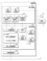
- FIG. FIG. 2 is a block diagram illustrating an internal configuration of an on-vehicle device included in the on-vehicle system.
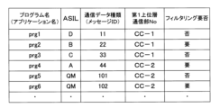
- FIG. 3 is an explanatory diagram showing an example of a communication control table. It is a flowchart which illustrates the processing by the 1st processing part and the 2nd processing part with which an in-vehicle device is provided.
- An object of the present disclosure is to provide an in-vehicle device and the like that can efficiently perform communication-related processing.
- An in-vehicle device is an in-vehicle device that is installed in a vehicle and connected to an in-vehicle network, and includes a first processing section and a second processing section connected to the first processing section. and a physical layer communication unit connected to the second processing unit, the first processing unit including a first upper layer communication unit corresponding to a layer higher than the physical layer communication unit, and the second processing unit
- the unit includes a second upper layer communication unit corresponding to a layer higher than the physical layer communication unit, and the first processing unit and the second processing unit are connected via the first upper layer communication unit,
- the second processing section and the physical layer communication section are connected via the second upper layer communication section.
- the in-vehicle device includes a plurality of processing units including a first processing unit and a second processing unit, and these processing units (first processing unit and second processing unit) are configured by, for example, a microcomputer.
- the in-vehicle device includes, for example, a physical layer communication section such as a CAN (Control Area Network) transceiver or an Ethernet (registered trademark) PHY section, and communicates with the in-vehicle device such as a CAN bus or an Ethernet cable via the physical layer communication section. Connected to the network.
- a physical layer communication section such as a CAN (Control Area Network) transceiver or an Ethernet (registered trademark) PHY section
- Each of the first processing unit (first microcomputer) and the second processing unit (second microcomputer) includes an upper layer communication unit corresponding to a layer higher than the physical layer communication unit, and the upper layer communication unit includes, for example, Consists of a CAN controller. That is, the first processing section includes a first upper layer communication section (CAN controller), and the second processing section includes a second upper layer communication section (CAN controller).
- the first processing section includes a first upper layer communication section (CAN controller)
- the second processing section includes a second upper layer communication section (CAN controller).
- the physical layer communication section, the second processing section (second upper layer communication section), and the first processing section (first upper layer communication section) are connected in series in this order to the in-vehicle network.
- the first processing section is connected to the physical layer communication section and the in-vehicle network via the second processing section, communication data output from the first processing section is transmitted to the in-vehicle network via the physical layer communication section.
- the output processing can be performed by the second processing section.
- the processing load related to communication control such as CAN control can be reduced, and the first processing section can be prevented from being occupied by communication control. Furthermore, it is possible to cause the first processing unit to efficiently execute logical operation processing related to vehicle control itself (realize logical functions as an on-vehicle device), such as processing based on AUTOSAR, for example.
- the first processing section has a processing capability higher than that of the second processing section.
- the processing capacity of the first processing section is higher than that of the second processing section that is directly connected to the physical layer communication section, the processing capacity of the first processing section is relatively high and the expensive first processing section is
- the first processing section can be effectively utilized.
- the second processing section which has a relatively low processing capacity and is inexpensive, has high real-time performance, it is possible to make the second processing section effective by having it perform communication control such as CAN control, which is mainly I/O control. It can be utilized. Logical calculation processing related to vehicle control, etc.
- Both processing related to communication control such as CAN control can be performed efficiently.
- the first processing section executes a plurality of programs related to control of the vehicle, and the second processing section executes the programs.
- processing related to selection of communication data to be output to the in-vehicle network is executed.
- the first processing section generates communication data by executing a plurality of programs related to vehicle control, and outputs the generated communication data to the second processing section.
- the second processing section performs processing related to the selection of communication data to be output to the in-vehicle network via the physical layer communication section from the communication data output from the first processing section, so unnecessary communication data (CAN messages, etc.) can be prevented from being output (transmitted) from the in-vehicle device to the in-vehicle network. Thereby, it is possible to suppress an increase in traffic (communication bandwidth usage) in the in-vehicle network.
- a plurality of the first upper layer communication sections are provided, and the plurality of first upper layer communication sections are connected to the second processing section. connected to the bus connection circuitry included in the section.
- the first processing section includes a plurality of first upper layer communication sections
- the second processing section includes a bus connection circuit to which each of the plurality of first upper layer communication sections is connected.
- the first processing section and the second processing section are connected through multiple paths by the plurality of first upper layer communication sections, and the communication path between the first processing section and the second processing section is This makes it possible to provide redundancy and increase communication bandwidth, thereby ensuring communication quality.
- the plurality of first upper layer communication units included in the first processing unit are connected to the bus connection circuit included in the second processing unit, so that the bus connection circuit is connected to a closed network inside the in-vehicle device (inside the in-vehicle device). CAN bus).
- communication between programs (applications) can be performed via the bus connection circuit (CAN bus inside the on-vehicle device), and communication between programs (applications) that is performed only inside the on-vehicle device can be performed via the bus connection circuit (CAN bus inside the on-vehicle device).
- In-vehicle device communication can be performed efficiently without being affected by the communication status of the in-vehicle network.
- the first processing unit executes a plurality of programs having different safety levels defined by ASIL, and the plurality of first upper layer communication units include: They are classified according to the security level of the program.
- the first processing unit executes multiple programs with different safety levels defined by ASIL (Automotive Safety Integrity Level), and communicates data output by executing these programs. Each of them is output to the second processing unit via any one of the plurality of first upper layer communication units.
- ASIL Automotive Safety Integrity Level
- These plurality of first upper layer communication units are classified according to the security level of the program, and the allocation is set to differ depending on the security level.
- the plurality of first upper layer communication units include a first upper layer communication unit (high-level first upper layer communication unit) to which communication data based on a program with a relatively high safety level is allocated, and a first upper layer communication unit with a relatively high safety level.
- first upper layer communication unit low-level first upper layer communication unit
- a first upper layer communication unit low-level first upper layer communication unit to which communication data based on a program with a relatively low level is allocated.
- the second processing section includes a filter section that filters communication data output from the first processing section via the bus connection circuit, and the filter The unit is interposed between the bus connection circuit and the second upper layer communication unit.
- the second processing section includes a filter section, and the filter section is provided interposed between the bus connection circuit and the second upper layer communication section.
- the second processing section uses the filter section to filter the communication data output from the first processing section via the bus connection circuit.
- the second processing section acquires the control signal output from the first processing section, and performs filtering by the filter section according to the acquired control signal. conduct.
- the second processing section performs filtering by controlling the filter section according to the control signal output from the first processing section when filtering the communication data output from the first processing section. .
- filtering according to the control signal communication data output from the first processing unit can be efficiently separated into communication data to be output to the in-vehicle network via the physical layer communication unit and communication data not to be output. can do.
- each of the first processing section and the second processing section includes a control signal I/F for transmitting and receiving the control signal.
- control signal generation section included in the first processing section generates a control signal indicating whether or not the communication data is subject to filtering, based on the communication data received by the first upper layer communication section. It is generated and output to the control I/F of the second processing section.
- the control signal generation section of the first processing section and the control I/F of the second processing section function as an I/F for control signals when transmitting and receiving control signals and the like between these functional parts.
- the control signal for performing processing related to filtering is transmitted through the control signal I/F of each of the first processing section and the second processing section (control signal generation section of the first processing section, control I/F of the second processing section). Since communication data such as a CAN message is transmitted and received via the first upper layer communication unit and the bus connection circuit through which communication data flows, it is possible to prevent the communication data from affecting the first upper layer communication unit and the bus connection circuit.
- a program according to an aspect of the present disclosure is connected to an in-vehicle network installed in a vehicle, and includes a first processing section, a second processing section connected to the first processing section, and the second processing section.
- a physical layer communication unit connected to the physical layer communication unit
- the first processing unit includes a first upper layer communication unit corresponding to a layer higher than the physical layer communication unit
- the second processing unit includes a first upper layer communication unit connected to the physical layer communication unit.
- the physical layer communication unit is a program connected via the second upper layer communication unit that causes a computer to execute processing, and causes the first processing unit to execute a plurality of programs related to control of the vehicle. , outputting communication data generated by execution of the program to the second processing unit via the first upper layer communication unit, and transmitting the communication data output from the first processing unit to the second processing unit. and performs a process of selecting communication data to be output to the in-vehicle network from among the received communication data.
- An information processing method includes a first processing section, a second processing section connected to the first processing section, and a second processing section connected to an in-vehicle network installed in a vehicle.
- a physical layer communication section connected to the processing section
- the first processing section includes a first upper layer communication section corresponding to a layer higher than the physical layer communication section
- the second processing section is connected to the physical layer communication section.
- the first processing unit and the second processing unit are connected via the first upper layer communication unit, and the second processing unit and the physical layer communication unit are connected via the second upper layer communication unit, and are an information processing method for causing a computer to execute processing, and the first processing unit is provided with a plurality of information related to the control of the vehicle.
- a program is executed, communication data generated by the execution of the program is output to the second processing unit via the first upper layer communication unit, and the communication data is output from the first processing unit to the second processing unit.
- the received communication data and performs a process of selecting communication data to be output to the in-vehicle network from among the received communication data.
- FIG. 1 is a schematic diagram illustrating a system configuration of an in-vehicle system S according to a first embodiment.
- the in-vehicle system S includes an in-vehicle device 1 mounted on a vehicle C, an in-vehicle ECU 3, a relay device 2 and an in-vehicle network 4 that communicably connect these devices.
- the in-vehicle device 1 may be an integrated ECU that controls the entire vehicle C in an integrated manner. Alternatively, the in-vehicle device 1 may be configured as a body ECU or the like that controls body-related actuators of the vehicle C. The in-vehicle device 1 may be connected to in-vehicle equipment such as a sensor or an actuator. Details of the in-vehicle device 1 will be described later.
- the in-vehicle ECU 3 includes a processing section, a storage section, an input/output I/F, an in-vehicle communication section, etc., and may be connected to in-vehicle devices such as sensors or actuators.
- the in-vehicle ECU 3 performs processing related to control of these in-vehicle devices.
- the in-vehicle ECU 3 may be an individual ECU connected under the in-vehicle device 1 functioning as an integrated ECU.
- the relay device 2 is configured by, for example, a CAN gateway or an Ethernet SW.
- a plurality of communication lines 41 such as a CAN bus or an Ethernet cable are connected to the relay device 2, and communication is transmitted and received between the in-vehicle ECUs 3 connected to each of these communication lines 41, and between the in-vehicle device 1 and the in-vehicle ECU 3.
- Relay data is configured by the in-vehicle network 4 a plurality of communication lines 41 connected to the relay device 2. Via the in-vehicle network 4, the in-vehicle device 1, the in-vehicle ECU 3, and the like are communicably connected.
- FIG. 2 is a block diagram illustrating the internal configuration of the in-vehicle device 1 included in the in-vehicle system S.
- the in-vehicle device 1 includes a first processing section 100, a second processing section 200, and a physical layer communication section 300.
- the first processing section 100, the second processing section 200, and the physical layer communication section 300 are connected, for example, by an internal bus or an inter-board connection.
- the physical layer communication unit 300, second processing unit 200, and first processing unit 100 are connected in series in this order from the in-vehicle network 4 side. becomes.
- the first processing unit 100 may be configured by a microcomputer or the like having higher processing capacity than the second processing unit 200 (second microcomputer).
- the first processing section 100 (first microcomputer) and the second processing section 200 (second microcomputer) may have a single chip configuration or a plurality of chip configurations.
- the in-vehicle device 1 may be configured with a chip having an eFPGA configuration in which a microcomputer (first processing unit 100) and an FPGA (second processing unit 200) are integrated. In this way, the in-vehicle device 1 may be configured as a multiprocessor system with a heterogeneous configuration.
- the first processing unit 100 (first microcomputer) is configured by, for example, a microcomputer, and efficiently executes logical operation processing related to vehicle C control itself, such as processing based on AUTOSAR (logical function as in-vehicle device 1). ).
- the first processing section 100 includes a first control section 101 , a first storage section 102 , a first internal bus 103 , a first upper layer communication section 104 , and a control signal generation section 105 . These first control section 101, first storage section 102, first upper layer communication section 104, and control signal generation section 105 are communicably connected via a first internal bus 103.
- the first control unit 101 is configured with a CPU (Central Processing Unit) or an MPU (Micro Processing Unit), and reads and executes a control program P (program product) and data stored in the first storage unit 102 in advance. By doing so, various control processing, calculation processing, etc. are performed.
- the control unit includes, for example, a single-core CPU, a single-core multi-CPU, a multi-core single CPU, and a multi-core multi-CPU.
- the control program P may include a plurality of programs (applications) having different safety levels defined by ASIL (Automotive Safety Integrity Level).
- the first control unit 101 performs logical operation processing related to vehicle C control itself, such as processing based on AUTOSAR, by executing these plural programs (applications) using pipeline parallelism or the like.
- the first control unit 101 outputs communication data generated by executing the plurality of programs (applications) to the first upper layer communication unit 104 via the first internal bus 103.
- the first storage unit 102 is a volatile memory element such as a RAM (Random Access Memory), a non-volatile memory element such as a ROM (Read Only Memory), an EEPROM (Electrically Erasable Programmable ROM), or a flash memory; It is configured by a combination of storage devices, and a control program P (program product) and data referred to during processing are stored in advance.
- the control program P (program product) stored in the first storage unit 102 may be one in which a control program P (program product) read from a recording medium M readable by the in-vehicle device 1 is stored.
- the control program P (program product) may be downloaded from an external computer (not shown) connected to a communication network (not shown) and stored in the first storage unit 102.
- the first storage unit 102 may store a communication control table, which will be described later.
- the first internal bus 103 is composed of, for example, a land, a conductive pattern, etc. formed on a substrate on which the first control section 101 and the like are mounted, or on a microcomputer substrate constituting the first processing section 100.
- the first control unit 101, first storage unit 102, first upper layer communication unit 104, and control signal generation unit 105 are communicably connected via the first internal bus 103.
- the first upper layer communication unit 104 is a communication unit compatible with a data link layer that is a layer higher than the physical layer, such as a CAN controller or an Ethernet controller.
- the first processing unit 100 may include two or more first upper layer communication units 104.
- the plurality of first upper layer communication units 104 may be classified according to the safety level of each program (application) executed by the first control unit 101.
- the division, that is, the allocation of the first upper layer communication unit 104 according to each program (application) may be defined in a communication control table described later.
- the control signal generation unit 105 is a hardware processing unit configured by, for example, an arithmetic circuit such as an ASIC (Application Specific Integrated Circuit) or an FPGA (Field Programmable Gate Array). Alternatively, the control signal generation unit 105 may be a software processing unit configured by an MPU or the like similarly to the first control unit 101.
- the control signal generation unit 105 acquires, monitors, or samples communication data generated and output by the first control unit 101 by executing a program via the first internal bus 103. For example, the control signal generation unit 105 reads a communication control table stored in the first storage unit 102, determines whether filtering of communication data output from the first control unit 101 is necessary, and performs filtering according to the determination result.
- control signal (control request) is output to the control I/F 205 of the second processing section 200.
- the control signal may be, for example, SPI, I2C, UART, or GPIO used on the board on which the first processing section 100 and the second processing section 200 are mounted, or between the boards.
- the control signal generation unit 105 functions as a control signal I/F when transmitting and receiving control signals and the like.
- the second processing unit 200 (second microcomputer) is composed of, for example, a microcomputer, and mainly executes communication control such as CAN control, and executes processing related to selection of communication data to be output from the in-vehicle device 1 to the in-vehicle network 4. .
- the second processing section 200 includes a second control section 201, a second storage section 202, a second internal bus 203, a second upper layer communication section 204, a control I/F 205, a circuit control section 206, a bus connection circuit 207, and a filter. 208.
- the second control unit 201, second storage unit 202, control I/F 205, and circuit control unit 206 are communicably connected via a second internal bus 203.
- the circuit control section 206 and the filter section 208 are communicably connected via an internal bus.
- the bus connection circuit 207, the filter section 208, and the second upper layer communication section 204 are communicably connected in series via an internal bus in this order.
- the bus connection circuit 207 is communicably connected to each of the plurality of first upper layer communication units 104 included in the first processing unit 100 via an internal bus.
- the second upper layer communication unit 204 is communicably connected to the physical layer communication unit 300 via an internal bus.
- the second control unit 201 is configured by a CPU or the like similarly to the first control unit 101, and reads out and executes the control program P (program product) and data stored in the second storage unit 202 in advance to perform various functions. It is designed to perform control processing, arithmetic processing, etc.
- the second control unit 201 may be configured as a simple processor with lower processing power than the first control unit 101. Alternatively, the second control unit 201 may be configured with an FPGA or the like.
- the second control unit 201 acquires the control signal (control request) output from the first processing unit 100 (control signal generation unit 105) via the control I/F 205, and performs processing such as interpretation of the acquired control signal. and performs processing for controlling the circuit control unit 206.
- the second control unit 201 generates a signal to control the circuit control unit 206 in response to a control signal (control request) from the first processing unit 100 (control signal generation unit 105), and transmits the signal to the circuit control unit. It may be outputted to 206.
- the second storage unit 202 is configured of a RAM, ROM, etc., similar to the first storage unit 102, and stores in advance the control program P (program product) and data to be referenced during processing.
- the storage capacity of the second storage unit 202 may be smaller than the storage capacity of the first storage unit 102. Thereby, the parts cost of the second processing section 200 can be reduced.
- the second internal bus 203 is composed of, for example, a land, a conductive pattern, etc. formed on a substrate on which the second control section 201 and the like are mounted, or a microcomputer substrate constituting the second processing section 200.
- the second control unit 201, second storage unit 202, control I/F 205, and circuit control unit 206 are communicably connected via the second internal bus 203.
- the control I/F 205 is an I/F that receives a control signal (control request) from the control signal generation unit 105 of the first processing unit 100, and functions as an I/F for control signals when transmitting and receiving control signals, etc. do.
- the control I/F 205 transmits the received control signal (control request) to the second control unit 201 via the second storage unit 202 configured with RAM or the like or by using a control register. It's okay.
- the circuit control unit 206 is a functional unit that provides an interface to a communication circuit including the filter unit 208 and the like using means such as a register.
- the circuit control unit 206 activates filtering processing by the filter unit 208, etc. in accordance with the control by the second control unit 201.
- the bus connection circuit 207 is constituted by, for example, an electric circuit provided on a board on which the second control section 201 and the like are mounted, or a microcomputer board constituting the second processing section 200. Alternatively, the bus connection circuit 207 may be configured (realized) as a logic circuit using programmable logic such as FPGA.
- the first upper layer communication section 104 of the first processing section 100 and the filter section 208 of the second processing section 200 are connected to the bus connection circuit 207, so that a network inside the vehicle-mounted device 1 (vehicle-mounted device 1 internal CAN bus, etc.).
- the filter section 208 is a functional section that performs filtering processing under the control of the circuit control section 206.
- the filter unit 208 may include a communication unit compatible with a data link layer such as a CAN controller, a filtering circuit, and the like.
- the communication unit corresponding to the data link layer may have the same configuration as the second upper layer communication unit 204 or may be connected to the bus connection circuit 207.
- the communication unit included in the filter unit 208 may control CAN communication or the like within the board on which the first processing unit 100 and the second processing unit 200 are mounted.
- the filter unit 208 In a steady state, that is, in a state where the circuit control unit 206 is not controlling the filter unit 208 (filtering circuit), the filter unit 208 (filtering circuit) does not filter the communication data outputted from the bus connection circuit 207 and transmits the communication data to the second upper layer communication unit. 204 may be set to perform transparency processing. Alternatively, the filter unit 208 may switch between filtering and non-filtering depending on the type of control signal (control request) output from the first processing unit 100 (filtering required control signal, filtering non-filtering control signal). .
- the second upper layer communication unit 204 is a communication unit compatible with a data link layer, etc., which is a layer higher than the physical layer, such as a CAN controller or an Ethernet controller.
- the second upper layer communication section 204 is provided interposed between the filter section 208 and the physical layer communication section 300.
- the second upper layer communication unit 204 controls CAN communication etc. outside the board on which the first processing unit 100 and the second processing unit 200 are mounted, that is, communication transmitted and received from the in-vehicle device 1 over the in-vehicle network 4. There may be.
- the physical layer communication unit 300 is composed of, for example, a CAN transceiver compatible with CAN or CAN-FD, or an Ethernet PHY unit compatible with Ethernet, and is compatible with a communication line 41 (physical layer) such as a CAN bus or an Ethernet cable. This is the communications department.
- the in-vehicle device 1 Via the physical layer communication unit 300, the in-vehicle device 1 is connected to the in-vehicle network 4, and is communicably connected to the in-vehicle ECU 3 connected to the in-vehicle network 4.
- the physical layer communication unit 300 configured with a CAN transceiver or the like may have a plurality of channels.
- FIG. 3 is an explanatory diagram showing an example of a communication control table.
- the communication control table is stored, for example, in the first storage unit 102 of the first processing unit 100 (first microcomputer).
- the first control unit 101 and control signal generation unit 105 included in the first processing unit 100 (first microcomputer) may refer to the communication control table and perform various processes.
- Management items (fields) defined in the communication control table include, for example, program name, ASIL, communication data type, first upper layer communication unit number, and whether or not filtering is necessary.
- the name (execution file name) of the program (application) executed by the first control unit 101 is stored in the program name management item.
- the ASIL management item stores an ASIL (Automotive Safety Integrity Level) value that defines the safety level of a program (application).
- the communication data type management item stores a value indicating the type of communication data output by executing a program (application).
- the value indicating the type of communication data may be, for example, a message ID (CAN-ID) in CAN communication, or a TCP port number in TCP/IP communication.
- the management item of the first upper layer communication unit No. stores the device number of the first upper layer communication unit 104 that is assigned according to the security level of the program (application).
- the first processing section 100 includes two first upper layer communication sections 104 (CC-1, CC-2).
- a program (application) with a higher security level than the first upper layer communication unit 104 (CC-2) is assigned to the first upper layer communication unit 104 (CC-1).
- the filtering necessity management item defines whether communication data output by executing a program (application) is subject to filtering by the second processing unit 200 (filter unit 208) (filtering necessity). be done.
- Communication data (communication data type) defined as requiring filtering corresponds to internal communication data that is not output to the in-vehicle network 4.
- the communication data (communication data type) defined as filtering not being performed corresponds to external communication data output to the in-vehicle network 4.
- FIG. 4 is a flowchart illustrating processing by the first processing unit 100 and second processing unit 200 included in the in-vehicle device 1. Although the processing by the first processing unit 100 and the second processing unit 200 are related to each other, the processing by the first processing unit 100 will be explained first, and the processing by the second processing unit 200 will be explained below.
- the first processing unit 100 outputs communication data (S101).
- the first control unit 101 of the first processing unit 100 executes a plurality of programs (applications) in parallel, and performs logical operation processing related to vehicle C control itself, such as processing based on AUTOSAR, using pipeline parallel processing, etc. It is executed using The first control unit 101 of the first processing unit 100 generates communication data by executing these programs.
- the first control unit 101 of the first processing unit 100 assigns (classifies) the generated communication data according to the safety level (ASIL: Automotive Safety Integrity Level) defined for each program. ) Output to the first upper layer communication unit 104 via the first internal bus 103.
- the first control unit 101 of the first processing unit 100 refers to the communication control table stored in the first storage unit 102 to determine which programs are assigned according to the safety level defined for each program.
- the first upper layer communication unit 104 may be specified.
- Each of the plurality of first upper layer communication units 104 is classified according to the safety level of the corresponding program, and communication data is transferred between the plurality of first upper layer communication units 104 to the bus connection circuit 207. Communication is performed between a plurality of programs being executed in parallel in the first control unit 101 (inter-process communication). Thereby, the bus connection circuit 207 of the second processing unit 200 can function as a network within the vehicle-mounted device 1 (CAN bus within the vehicle-mounted device 1).
- the first processing unit 100 determines whether filtering is necessary for the output communication data (S102).
- the control signal generation section 105 of the first processing section 100 alone or in cooperation with the first processing section 100, transmits communication data generated and outputted by the first control section 101 by executing a program to the first internal
- the information is acquired, monitored, or sampled via the bus 103 to determine whether or not filtering of the bus connection circuit 207 is necessary.
- the control signal generation unit 105 of the first processing unit 100 may specify the type of communication data of the communication data output from the first processing unit 100 when determining whether or not filtering is necessary.
- the control signal generation unit 105 of the first processing unit 100 refers to the communication control table stored in the first storage unit 102 for the identified communication data type, so that the communication data type is not filtered. It may be possible to determine whether filtering is necessary or not (necessity of filtering).
- the first processing unit 100 If it is determined that filtering is necessary (S102: YES), the first processing unit 100 outputs a control signal for causing the second processing unit 200 to perform filtering. (S103).
- the control signal generation unit 105 of the first processing unit 100 determines that filtering is necessary for the communication data output from the first processing unit 100
- the control signal generation unit 105 controls the second processing unit 200 to perform filtering.
- a signal (control request) is generated, and the generated control signal (control request) is output to the control I/F 205 of the second processing unit 200 .
- the second control unit 201 of the second processing unit 200 acquires the control signal (control request) output from the control signal generation unit 105 of the first processing unit 100 via the control I/F 205.
- the first processing unit 100 After executing S103, or when it is determined that filtering is not necessary (S102: NO), the first processing unit 100 performs a loop process to execute the process from S101 again. When the first processing unit 100 determines that filtering is not necessary, it may output a control signal (a control signal for transparently processing communication data) indicating that filtering is not necessary.
- a control signal a control signal for transparently processing communication data
- the second processing unit 200 determines whether a control signal for performing filtering has been obtained from the first processing unit 100 (T101).
- the second control unit 201 of the second processing unit 200 continuously performs a process of waiting for a control signal (control request) output from the control signal generation unit 105 of the first processing unit 100 via the control I/F 205. and determines whether or not a control signal is acquired from the control I/F 205.
- the control I/F 205 may transmit a control signal (control request) to the second control unit 201 using, for example, the second storage unit 202 such as a control register or RAM.
- the second processing unit 200 performs filtering on the communication data output from the first processing unit 100 (T102).
- a control signal a control signal for executing filtering
- the second control unit 201 of the second processing unit 200 performs processing such as interpretation of the control signal and controls the circuit control unit 206. do.
- the circuit control unit 206 controlled by the second control unit 201 activates the filtering function of the filter unit 208 and performs filtering on the communication data output from the first processing unit 100.
- the communication data output from the first processing unit 100 to the second processing unit 200 is discarded without being output to the physical layer communication unit 300, and the communication data is output from the in-vehicle device 1 to the in-vehicle network 4. You can prevent it from happening.
- the second processing unit 200 does not filter the communication data output from the first processing unit 100.
- the filter unit 208 performs transparent processing to output communication data output from the bus connection circuit 207 to the second upper layer communication unit 204 without filtering it. It is set as follows. Therefore, the communication data output from the first processing section 100 to the second processing section 200 is output from the second processing section 200 to the physical layer communication section 300 without being filtered by the second processing section 200. It is output to the in-vehicle network 4 via the physical layer communication unit 300.
- the second processing unit 200 acquires a control signal (a control signal for transparently processing communication data) indicating that filtering is not necessary from the first processing unit 100, the second processing unit 200 The filtering may not be performed on the communication data output from the. After executing T101, or when determining that the control signal has not been acquired (T101: NO), the second processing unit 200 performs loop processing to execute T101 again.
- a control signal a control signal for transparently processing communication data
- the second control unit 201 switches the circuit according to the type of the control signal.
- the control unit 206 and the filter unit 208 may also be controlled. That is, when the control signal from the first processing section 100 is a control signal for performing filtering (filtering required control signal), the second control section 201 controls the circuit control section 206 and causes the filter section 208 to perform filtering. It may also be something that causes a process to be executed.
- the control signal from the first processing unit 100 is a control signal indicating that filtering is not necessary (filtering non-control signal)
- the second control unit 201 controls the circuit control unit 206 and controls the filtering unit 208. It is also possible to transparently process the communication data without executing the filtering process.
- the in-vehicle device 1 is configured with a plurality of processing units (microcomputers) including the first processing unit 100 (first microcomputer) and the second processing unit 200 (second microcomputer), each processing unit Applications (software) to be executed are distributed according to the processing capacity of the controller, that is, a processing unit (second processing unit 200) with relatively low processing capacity is assigned to communication control such as CAN control.
- microcomputers microcomputers
- first processing unit 100 first microcomputer
- second processing unit 200 second microcomputer
- the processing unit (first processing unit 100) with high processing ability from being occupied by communication control, and it is possible to improve the processing efficiency of the program. Furthermore, it is possible to suppress an increase in the number of communication units such as a CAN controller installed in the in-vehicle device 1, and to suppress an increase in parts cost and product weight due to the addition of hardware. be able to. Furthermore, communication between these multiple applications is performed within the in-vehicle device 1, and unnecessary communication data (CAN messages, etc.) is prevented from being output (sent) from the in-vehicle device 1 to the in-vehicle network 4. can do. Furthermore, it is possible to eliminate the need for processing such as simulation of CAN signals and proxy transmission by software.
- the filter section 208 only necessary communication data (signals) can be selected and sent to the communication line 41 (in-vehicle network 4) such as a CAN bus, and the amount of communication in the in-vehicle network 4 can be reduced. .
- In-vehicle system 1 In-vehicle device 100 First processing section (first microcomputer) 101 First control unit 102 First storage unit 103 First internal bus 104 First upper layer communication unit 105 Control signal generation unit (control signal I/F) 200 Second processing section (second microcomputer) 201 Second control unit 202 Second storage unit 203 Second internal bus 204 Second upper layer communication unit 205 Control I/F (control signal I/F) 206 Circuit control section 207 Bus connection circuit 208 Filter section 300 Physical layer communication section P Control program (program product) M Recording medium 2 Relay device 3 In-vehicle ECU 4 In-vehicle network 41 Communication line
Landscapes
- Engineering & Computer Science (AREA)
- Computer Networks & Wireless Communication (AREA)
- Signal Processing (AREA)
- Small-Scale Networks (AREA)
- Hardware Redundancy (AREA)
Abstract
Description
本出願は、2022年4月27日出願の日本出願第2022-073430号に基づく優先権を主張し、前記日本出願に記載された全ての記載内容を援用するものである。
特許文献1の車載ECUにおいては、当該車載ECUが備える制御部により複数のアプリケーションが実行される場合、これらアプリケーションの動作に応じて実行される通信に関する処理を効率的に行う点について考慮されていない。
本開示の一態様によれば、通信に関する処理を効率的に行う車載装置等を提供することができる。
最初に本開示の実施態様を列挙して説明する。また、以下に記載する実施形態の少なくとも一部を任意に組み合わせてもよい。
本開示をその実施の形態を示す図面に基づいて具体的に説明する。本開示の実施形態に係る車載装置1を、以下に図面を参照しつつ説明する。なお、本開示はこれらの例示に限定されるものではなく、請求の範囲によって示され、請求の範囲と均等の意味及び範囲内での全ての変更が含まれることが意図される。
以下、実施の形態について図面に基づいて説明する。図1は、実施形態1に係る車載システムSのシステム構成を例示する模式図である。車載システムSは、車両Cに搭載される車載装置1、車載ECU3、これらを通信可能に接続する中継装置2及び車載ネットワーク4により構成される。
S 車載システム
1 車載装置
100 第1処理部(第1マイコン)
101 第1制御部
102 第1記憶部
103 第1内部バス
104 第1上位層通信部
105 制御信号生成部(制御信号用I/F)
200 第2処理部(第2マイコン)
201 第2制御部
202 第2記憶部
203 第2内部バス
204 第2上位層通信部
205 制御I/F(制御信号用I/F)
206 回路制御部
207 バス接続回路
208 フィルタ部
300 物理層通信部
P 制御プログラム(プログラム製品)
M 記録媒体
2 中継装置
3 車載ECU
4 車載ネットワーク
41 通信線
Claims (10)
- 車両に搭載される車載ネットワークに接続される車載装置であって、
第1処理部と、
前記第1処理部に接続される第2処理部と、
前記第2処理部に接続される物理層通信部とを備え、
前記第1処理部は、前記物理層通信部より上位層に対応する第1上位層通信部を含み、
前記第2処理部は、前記物理層通信部より上位層に対応する第2上位層通信部を含み、
前記第1処理部と前記第2処理部とは、前記第1上位層通信部を介して接続され、
前記第2処理部と前記物理層通信部とは、前記第2上位層通信部を介して接続される
車載装置。 - 前記第1処理部の処理能力は、前記第2処理部の処理能力よりも高い
請求項1に記載の車載装置。 - 前記第1処理部は、前記車両の制御に関する複数のプログラムを実行し、
前記第2処理部は、前記第1処理部がプログラムを実行することにより生成される通信データにおいて、前記車載ネットワークに出力する通信データの選別に関する処理を実行する
請求項2に記載の車載装置。 - 前記第1処理部において、前記第1上位層通信部は複数設けられており、
複数の前記第1上位層通信部は、前記第2処理部が含むバス接続回路に接続される
請求項1に記載の車載装置。 - 前記第1処理部は、ASILにて定義される安全性レベルが異なる複数のプログラムを実行し、
複数の前記第1上位層通信部は、プログラムの安全性レベルに応じて区分けされている
請求項4に記載の車載装置。 - 前記第2処理部は、前記バス接続回路を介して前記第1処理部から出力された通信データを、フィルタリングするフィルタ部を含み、
前記フィルタ部は、前記バス接続回路と前記第2上位層通信部との間に介在して設けられている
請求項4又は請求項5に記載の車載装置。 - 前記第2処理部は、
前記第1処理部から出力された制御信号を取得し、
取得した制御信号に応じて、前記フィルタ部によるフィルタリングを行う
請求項6に記載の車載装置。 - 前記第1処理部及び前記第2処理部それぞれは、前記制御信号を送受信するための制御信号用I/Fを備える
請求項7に記載の車載装置。 - 車両に搭載される車載ネットワークに接続され、
第1処理部と、
前記第1処理部に接続される第2処理部と、
前記第2処理部に接続される物理層通信部とを備え、
前記第1処理部は、前記物理層通信部より上位層に対応する第1上位層通信部を含み、
前記第2処理部は、前記物理層通信部より上位層に対応する第2上位層通信部を含み、
前記第1処理部と前記第2処理部とは、前記第1上位層通信部を介して接続され、
前記第2処理部と前記物理層通信部とは、前記第2上位層通信部を介して接続される、
コンピュータに処理を実行させるプログラムであって、
前記第1処理部に、
前記車両の制御に関する複数のプログラムを実行し、
前記プログラムの実行より生成した通信データを前記第1上位層通信部を介して、前記第2処理部に出力し、
前記第2処理部に、
前記第1処理部から出力された前記通信データを受信し、
受信した前記通信データにおいて、前記車載ネットワークに出力する通信データを選別する
処理を実行させるプログラム。 - 車両に搭載される車載ネットワークに接続され、
第1処理部と、
前記第1処理部に接続される第2処理部と、
前記第2処理部に接続される物理層通信部とを備え、
前記第1処理部は、前記物理層通信部より上位層に対応する第1上位層通信部を含み、
前記第2処理部は、前記物理層通信部より上位層に対応する第2上位層通信部を含み、
前記第1処理部と前記第2処理部とは、前記第1上位層通信部を介して接続され、
前記第2処理部と前記物理層通信部とは、前記第2上位層通信部を介して接続される、
コンピュータに処理を実行させる情報処理方法であって、
前記第1処理部に、
前記車両の制御に関する複数のプログラムを実行し、
前記プログラムの実行より生成した通信データを前記第1上位層通信部を介して、前記第2処理部に出力し、
前記第2処理部に、
前記第1処理部から出力された前記通信データを受信し、
受信した前記通信データにおいて、前記車載ネットワークに出力する通信データを選別する
処理を実行させる情報処理方法。
Priority Applications (3)
| Application Number | Priority Date | Filing Date | Title |
|---|---|---|---|
| US18/859,349 US20250267038A1 (en) | 2022-04-27 | 2023-04-10 | In-vehicle device, program, and information processing method |
| CN202380033634.4A CN118947090A (zh) | 2022-04-27 | 2023-04-10 | 车载装置、程序及信息处理方法 |
| JP2024517954A JP7718586B2 (ja) | 2022-04-27 | 2023-04-10 | 車載装置、プログラム及び情報処理方法 |
Applications Claiming Priority (2)
| Application Number | Priority Date | Filing Date | Title |
|---|---|---|---|
| JP2022-073430 | 2022-04-27 | ||
| JP2022073430 | 2022-04-27 |
Publications (1)
| Publication Number | Publication Date |
|---|---|
| WO2023210314A1 true WO2023210314A1 (ja) | 2023-11-02 |
Family
ID=88518387
Family Applications (1)
| Application Number | Title | Priority Date | Filing Date |
|---|---|---|---|
| PCT/JP2023/014479 Ceased WO2023210314A1 (ja) | 2022-04-27 | 2023-04-10 | 車載装置、プログラム及び情報処理方法 |
Country Status (4)
| Country | Link |
|---|---|
| US (1) | US20250267038A1 (ja) |
| JP (1) | JP7718586B2 (ja) |
| CN (1) | CN118947090A (ja) |
| WO (1) | WO2023210314A1 (ja) |
Citations (2)
| Publication number | Priority date | Publication date | Assignee | Title |
|---|---|---|---|---|
| JP2019125867A (ja) * | 2018-01-12 | 2019-07-25 | パナソニックIpマネジメント株式会社 | 監視装置、監視システム及び監視方法 |
| JP2021138263A (ja) * | 2020-03-04 | 2021-09-16 | 住友電装株式会社 | 車載中継装置、及びコンピュータプログラム |
Family Cites Families (6)
| Publication number | Priority date | Publication date | Assignee | Title |
|---|---|---|---|---|
| EP2680147A3 (en) * | 2012-06-26 | 2014-05-21 | LG Electronics, Inc. | In-vehicle infotainment processor and data processing method using the same |
| US9811247B2 (en) * | 2013-11-25 | 2017-11-07 | Lg Electronics Inc. | In-vehicle infotainment device and image display method using the same |
| US10437680B2 (en) * | 2015-11-13 | 2019-10-08 | Kabushiki Kaisha Toshiba | Relay apparatus, relay method, and computer program product |
| JP6515915B2 (ja) * | 2016-12-26 | 2019-05-22 | トヨタ自動車株式会社 | 車載ネットワークシステム |
| US11870603B2 (en) * | 2021-12-31 | 2024-01-09 | Nxp B.V. | Controller area network termination scheme |
| CN114545906B (zh) * | 2022-02-28 | 2024-05-10 | 奇瑞汽车股份有限公司 | 车载以太网网关及车辆 |
-
2023
- 2023-04-10 US US18/859,349 patent/US20250267038A1/en active Pending
- 2023-04-10 JP JP2024517954A patent/JP7718586B2/ja active Active
- 2023-04-10 CN CN202380033634.4A patent/CN118947090A/zh active Pending
- 2023-04-10 WO PCT/JP2023/014479 patent/WO2023210314A1/ja not_active Ceased
Patent Citations (2)
| Publication number | Priority date | Publication date | Assignee | Title |
|---|---|---|---|---|
| JP2019125867A (ja) * | 2018-01-12 | 2019-07-25 | パナソニックIpマネジメント株式会社 | 監視装置、監視システム及び監視方法 |
| JP2021138263A (ja) * | 2020-03-04 | 2021-09-16 | 住友電装株式会社 | 車載中継装置、及びコンピュータプログラム |
Also Published As
| Publication number | Publication date |
|---|---|
| US20250267038A1 (en) | 2025-08-21 |
| JP7718586B2 (ja) | 2025-08-05 |
| CN118947090A (zh) | 2024-11-12 |
| JPWO2023210314A1 (ja) | 2023-11-02 |
Similar Documents
| Publication | Publication Date | Title |
|---|---|---|
| US20010002449A1 (en) | Processor unit for a data-processing-aided electronic control system in a motor vehicle | |
| CN109116777B (zh) | 汽车电子系统体系架构 | |
| KR100900882B1 (ko) | 상호 상이한 복수의 네트워크 프로토콜을 사용하는 차량에적용되는 게이트웨이 디바이스, 네트워크 시스템 및 데이터변환방법 | |
| US10214189B2 (en) | Interface for interchanging data between redundant programs for controlling a motor vehicle | |
| US20250039015A1 (en) | Zonal control architecture for software-defined vehicle | |
| JP7471756B2 (ja) | 車両システム | |
| US20090210171A1 (en) | Monitoring device and monitoring method for a sensor, and sensor | |
| Kenjić et al. | Connectivity challenges in automotive solutions | |
| WO2024251413A1 (en) | System on chip automotive safety monitoring | |
| CN110291504B (zh) | 用于机动车的控制器和相应的机动车 | |
| KR20160087274A (ko) | 오토사 기반의 전자제어유닛 멀티코어 아키텍처 및 이를 포함하는 차량 | |
| US20090013170A1 (en) | Control Device With Configurable Hardware Modules | |
| JP5542760B2 (ja) | 車載制御装置 | |
| JP7718586B2 (ja) | 車載装置、プログラム及び情報処理方法 | |
| CN118613787A (zh) | 用于基于数据云的功能的参与式安全协议 | |
| US10958472B2 (en) | Direct access to bus signals in a motor vehicle | |
| CN120768931A (zh) | 车辆辅助驾驶系统 | |
| US20090187605A1 (en) | Vehicle Control Apparatus | |
| WO2023228769A1 (ja) | 車載装置 | |
| JP7733816B2 (ja) | 車載電子装置 | |
| CN117940321A (zh) | 车辆系统 | |
| JP7654073B2 (ja) | 車両用制御装置 | |
| Park et al. | An OSGi based in-vehicle gateway platform architecture for improved sensor extensibility and interoperability | |
| JP6979630B2 (ja) | 監視装置、監視方法及びプログラム | |
| US12594895B2 (en) | Vehicle-mounted apparatus, program, and information processing method |
Legal Events
| Date | Code | Title | Description |
|---|---|---|---|
| 121 | Ep: the epo has been informed by wipo that ep was designated in this application |
Ref document number: 23796060 Country of ref document: EP Kind code of ref document: A1 |
|
| ENP | Entry into the national phase |
Ref document number: 2024517954 Country of ref document: JP Kind code of ref document: A |
|
| WWE | Wipo information: entry into national phase |
Ref document number: 202380033634.4 Country of ref document: CN |
|
| WWE | Wipo information: entry into national phase |
Ref document number: 18859349 Country of ref document: US |
|
| NENP | Non-entry into the national phase |
Ref country code: DE |
|
| 122 | Ep: pct application non-entry in european phase |
Ref document number: 23796060 Country of ref document: EP Kind code of ref document: A1 |
|
| WWP | Wipo information: published in national office |
Ref document number: 18859349 Country of ref document: US |