WO2023210307A1 - Air blowing system - Google Patents
Air blowing system Download PDFInfo
- Publication number
- WO2023210307A1 WO2023210307A1 PCT/JP2023/014439 JP2023014439W WO2023210307A1 WO 2023210307 A1 WO2023210307 A1 WO 2023210307A1 JP 2023014439 W JP2023014439 W JP 2023014439W WO 2023210307 A1 WO2023210307 A1 WO 2023210307A1
- Authority
- WO
- WIPO (PCT)
- Prior art keywords
- air
- conditioned space
- blowing
- control device
- space
- Prior art date
Links
- 238000007664 blowing Methods 0.000 title claims abstract description 59
- 230000007246 mechanism Effects 0.000 claims abstract description 42
- 238000001514 detection method Methods 0.000 claims description 73
- 238000009423 ventilation Methods 0.000 claims description 56
- 230000001143 conditioned effect Effects 0.000 claims description 17
- 238000003756 stirring Methods 0.000 claims description 17
- 239000004480 active ingredient Substances 0.000 claims description 9
- 238000004891 communication Methods 0.000 description 20
- 238000003780 insertion Methods 0.000 description 10
- 230000037431 insertion Effects 0.000 description 10
- 239000012141 concentrate Substances 0.000 description 5
- XLYOFNOQVPJJNP-UHFFFAOYSA-N water Substances O XLYOFNOQVPJJNP-UHFFFAOYSA-N 0.000 description 5
- 230000006870 function Effects 0.000 description 4
- 230000010354 integration Effects 0.000 description 4
- 238000012986 modification Methods 0.000 description 4
- 230000004048 modification Effects 0.000 description 4
- 238000012545 processing Methods 0.000 description 4
- 229910001335 Galvanized steel Inorganic materials 0.000 description 3
- 241000700605 Viruses Species 0.000 description 3
- 238000010586 diagram Methods 0.000 description 3
- 230000000694 effects Effects 0.000 description 3
- 239000008397 galvanized steel Substances 0.000 description 3
- 229910052751 metal Inorganic materials 0.000 description 3
- 239000002184 metal Substances 0.000 description 3
- 238000004378 air conditioning Methods 0.000 description 2
- 230000003020 moisturizing effect Effects 0.000 description 2
- 230000000149 penetrating effect Effects 0.000 description 2
- 230000002093 peripheral effect Effects 0.000 description 2
- 239000004743 Polypropylene Substances 0.000 description 1
- 229910052782 aluminium Inorganic materials 0.000 description 1
- XAGFODPZIPBFFR-UHFFFAOYSA-N aluminium Chemical compound [Al] XAGFODPZIPBFFR-UHFFFAOYSA-N 0.000 description 1
- 238000003491 array Methods 0.000 description 1
- 230000003749 cleanliness Effects 0.000 description 1
- 238000001816 cooling Methods 0.000 description 1
- 238000004332 deodorization Methods 0.000 description 1
- 230000001877 deodorizing effect Effects 0.000 description 1
- 238000013461 design Methods 0.000 description 1
- 230000000249 desinfective effect Effects 0.000 description 1
- 238000007599 discharging Methods 0.000 description 1
- 239000003205 fragrance Substances 0.000 description 1
- 238000010438 heat treatment Methods 0.000 description 1
- 230000000415 inactivating effect Effects 0.000 description 1
- 230000002779 inactivation Effects 0.000 description 1
- 238000009434 installation Methods 0.000 description 1
- 150000002500 ions Chemical class 0.000 description 1
- 238000005259 measurement Methods 0.000 description 1
- 238000000465 moulding Methods 0.000 description 1
- NJPPVKZQTLUDBO-UHFFFAOYSA-N novaluron Chemical compound C1=C(Cl)C(OC(F)(F)C(OC(F)(F)F)F)=CC=C1NC(=O)NC(=O)C1=C(F)C=CC=C1F NJPPVKZQTLUDBO-UHFFFAOYSA-N 0.000 description 1
- 239000002245 particle Substances 0.000 description 1
- -1 polypropylene Polymers 0.000 description 1
- 229920001155 polypropylene Polymers 0.000 description 1
- 238000004321 preservation Methods 0.000 description 1
- 239000011347 resin Substances 0.000 description 1
- 229920005989 resin Polymers 0.000 description 1
- 239000004065 semiconductor Substances 0.000 description 1
- 239000010935 stainless steel Substances 0.000 description 1
- 229910001220 stainless steel Inorganic materials 0.000 description 1
Images


Classifications
-
- F—MECHANICAL ENGINEERING; LIGHTING; HEATING; WEAPONS; BLASTING
- F24—HEATING; RANGES; VENTILATING
- F24F—AIR-CONDITIONING; AIR-HUMIDIFICATION; VENTILATION; USE OF AIR CURRENTS FOR SCREENING
- F24F11/00—Control or safety arrangements
- F24F11/70—Control systems characterised by their outputs; Constructional details thereof
- F24F11/72—Control systems characterised by their outputs; Constructional details thereof for controlling the supply of treated air, e.g. its pressure
- F24F11/79—Control systems characterised by their outputs; Constructional details thereof for controlling the supply of treated air, e.g. its pressure for controlling the direction of the supplied air
-
- F—MECHANICAL ENGINEERING; LIGHTING; HEATING; WEAPONS; BLASTING
- F24—HEATING; RANGES; VENTILATING
- F24F—AIR-CONDITIONING; AIR-HUMIDIFICATION; VENTILATION; USE OF AIR CURRENTS FOR SCREENING
- F24F13/00—Details common to, or for air-conditioning, air-humidification, ventilation or use of air currents for screening
- F24F13/02—Ducting arrangements
- F24F13/06—Outlets for directing or distributing air into rooms or spaces, e.g. ceiling air diffuser
- F24F13/075—Outlets for directing or distributing air into rooms or spaces, e.g. ceiling air diffuser having parallel rods or lamellae directing the outflow, e.g. the rods or lamellae being individually adjustable
-
- F—MECHANICAL ENGINEERING; LIGHTING; HEATING; WEAPONS; BLASTING
- F24—HEATING; RANGES; VENTILATING
- F24F—AIR-CONDITIONING; AIR-HUMIDIFICATION; VENTILATION; USE OF AIR CURRENTS FOR SCREENING
- F24F7/00—Ventilation
- F24F7/007—Ventilation with forced flow
-
- F—MECHANICAL ENGINEERING; LIGHTING; HEATING; WEAPONS; BLASTING
- F24—HEATING; RANGES; VENTILATING
- F24F—AIR-CONDITIONING; AIR-HUMIDIFICATION; VENTILATION; USE OF AIR CURRENTS FOR SCREENING
- F24F7/00—Ventilation
- F24F7/04—Ventilation with ducting systems, e.g. by double walls; with natural circulation
- F24F7/06—Ventilation with ducting systems, e.g. by double walls; with natural circulation with forced air circulation, e.g. by fan positioning of a ventilator in or against a conduit
-
- F—MECHANICAL ENGINEERING; LIGHTING; HEATING; WEAPONS; BLASTING
- F24—HEATING; RANGES; VENTILATING
- F24F—AIR-CONDITIONING; AIR-HUMIDIFICATION; VENTILATION; USE OF AIR CURRENTS FOR SCREENING
- F24F8/00—Treatment, e.g. purification, of air supplied to human living or working spaces otherwise than by heating, cooling, humidifying or drying
- F24F8/10—Treatment, e.g. purification, of air supplied to human living or working spaces otherwise than by heating, cooling, humidifying or drying by separation, e.g. by filtering
- F24F8/192—Treatment, e.g. purification, of air supplied to human living or working spaces otherwise than by heating, cooling, humidifying or drying by separation, e.g. by filtering by electrical means, e.g. by applying electrostatic fields or high voltages
-
- F—MECHANICAL ENGINEERING; LIGHTING; HEATING; WEAPONS; BLASTING
- F24—HEATING; RANGES; VENTILATING
- F24F—AIR-CONDITIONING; AIR-HUMIDIFICATION; VENTILATION; USE OF AIR CURRENTS FOR SCREENING
- F24F8/00—Treatment, e.g. purification, of air supplied to human living or working spaces otherwise than by heating, cooling, humidifying or drying
- F24F8/30—Treatment, e.g. purification, of air supplied to human living or working spaces otherwise than by heating, cooling, humidifying or drying by ionisation
-
- F—MECHANICAL ENGINEERING; LIGHTING; HEATING; WEAPONS; BLASTING
- F24—HEATING; RANGES; VENTILATING
- F24F—AIR-CONDITIONING; AIR-HUMIDIFICATION; VENTILATION; USE OF AIR CURRENTS FOR SCREENING
- F24F2130/00—Control inputs relating to environmental factors not covered by group F24F2110/00
- F24F2130/10—Weather information or forecasts
Definitions
- the present disclosure relates to a ventilation system.
- the air purifying device of Patent Document 1 includes a casing having an air inlet and an air outlet, and a guide plate is provided inside the casing.
- the guide plate is arranged approximately at the center of the casing, and a gap is provided between the guide plate and the peripheral plate of the casing to allow air to pass therethrough.
- a baffle plate is provided below the guide plate to cover the inner peripheral edge of the air outlet.
- the guide plate guides the air sent into the casing by the fan toward the circumferential plate and sends it toward the air outlet through the gap.
- An opening is formed at a position corresponding to the center of the mouth shape of the air outlet, and the baffle plate rectifies the flow of air toward the opening.
- An object of the present disclosure is to provide a ventilation system that can freely adjust the flow of air within an air-conditioned space.
- a ventilation system includes a plurality of ventilation devices installed on the ceiling of an air-conditioned space.
- Each of the plurality of air blowers includes a housing, a current plate, and a drive mechanism.
- the casing is formed into a box shape having an internal space, and includes an intake port for feeding supply air into the internal space, and an intake port for blowing out the supply air that has passed through the internal space as blast air into the air-conditioned space. It has an air outlet and a constriction part that narrows the internal space toward the periphery of the air outlet.
- the baffle plate is arranged between the air inlet and the air outlet.
- the drive mechanism moves the current plate.
- FIG. 1 is a block diagram showing the configuration of an air blowing system according to an embodiment.
- FIG. 2 is a perspective view showing the arrangement of a blower and an air conditioner included in the blower system.
- FIG. 3 is a perspective view showing the arrangement of a blower and an air conditioner included in the blower system.
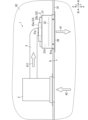
- FIG. 4 is a side view showing a blower and an air conditioner included in the blower system.
- FIG. 5 is a perspective view showing a blower device included in the blower system.
- FIG. 6 is a perspective view showing a blower device included in the blower system.
- FIG. 7 is a plan view showing a rectifying plate included in the blower device.
- FIG. 8 is a partially cutaway side view showing the mounting structure of the rectifying plate same as above.
- FIG. 9A is a cross-sectional view showing the operation of the blower device as described above.
- FIG. 9B is a cross-sectional view showing another operation of the blower device as described above.
- FIG. 10 is a perspective view illustrating the stirring mode of the air blowing system.
- FIG. 11 is a perspective view showing the arrangement of a human sensor in the air blowing system.
- FIG. 12 is a perspective view illustrating the spot mode of the air blowing system.
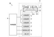
- FIG. 13 is a block diagram showing the configuration of the ventilation system of the first modification.
- FIG. 14 is a block diagram showing the configuration of a second modified example of the ventilation system.
- the present embodiment generally relates to a ventilation system. More specifically, the present disclosure relates to a blower system that includes a plurality of blowers.
- the X-axis, Y-axis, and Z-axis that are orthogonal to each other are defined in FIG. 5.
- one of the two directions along the X axis is defined as the right direction, and the other direction is defined as the left direction.
- one direction out of both directions along the Y axis is defined as the front direction, and the other direction is defined as the rear direction.
- one direction among the two directions along the Z-axis is defined as an upward direction, and the other direction is defined as a downward direction. Note that the directions described above do not limit the actual usage of the ventilation system, but are used to facilitate understanding of the ventilation system.
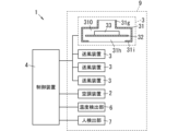
- FIG. 1 shows a block configuration of a ventilation system 1 of this embodiment.
- the ventilation system 1 is used, for example, in facilities such as office buildings, offices, stores, factories, or commercial facilities. Moreover, the ventilation system 1 may be used in a residential unit of an apartment complex, a detached house, or the like.
- the ventilation system 1 includes a plurality of (four in FIG. 1) ventilation devices 3.
- the plurality of blower devices 3 are installed on the ceiling 91 of the air-conditioned space 9, as shown in FIGS. 2 and 3.
- Each of the plurality of air blowers 3 includes a housing 31, a rectifying plate 32, and a drive mechanism 33, as shown in FIG.
- the casing 31 is formed in a box shape with an internal space 310, and includes an intake port 31g for feeding supply air A11 (see FIG. 4) into the internal space 310, and a blowing air for supply air A11 that has passed through the internal space 310.
- A1 see FIG.
- the current plate 32 is arranged between the intake port 31g and the ventilation port 31h.
- the drive mechanism 33 moves the current plate 32.
- the above-mentioned blower device 3 can make the blowing air A1 (see FIGS. 9A and 9B) a directional airflow by the rectifying plate 32 arranged between the air intake port 31g and the air blowing port 31h. Furthermore, the blowing device 3 can control the directivity of the blown air A1 by moving the rectifying plate 32 by the drive mechanism 33. Therefore, the ventilation system 1 including the plurality of ventilation devices 3 can freely adjust the flow of air within the air-conditioned space 9.
- the ventilation system 1 includes an air conditioner 2, four ventilation devices 3, a control device 4, a duct 5, a temperature detection section 6, and a person detection section 7. Equipped with
- the four blowers 3 are installed on the ceiling 91 of the air-conditioned space 9, as shown in FIGS. 2 and 3.
- the air-conditioned space 9 has a rectangular box shape.
- the four blowers 3 are installed on the ceiling 91 at locations corresponding to the four vertices of a rectangle. That is, the four air blowers 3 are installed on the ceiling 91 so as not to be lined up on the same straight line.
- the blower device 3 is attached to the ceiling 91 through the ceiling 91, and blows air A1 downward from the ceiling 91.
- each of the four air blowers 3 is called air blowers 3A, 3B, 3C, and 3D.
- the blowers 3A, 3B, 3C, and 3D are arranged counterclockwise in the order of 3A, 3B, 3C, and 3D when viewed from above.
- the air conditioner 2 is installed on the ceiling 91 of the air conditioned space 9, as shown in FIGS. 2 and 3.
- the air conditioner 2 is installed on the ceiling 91 at a location surrounded by the four blowers 3.
- the air conditioner 2 is arranged closer to the blowers 3C and 3D than the blowers 3A and 3B.
- the air conditioner 2 is attached to the ceiling 91 by penetrating the ceiling 91 as shown in FIG. 4, sucks air A2 in the air conditioned space 9, and supplies conditioned air with the temperature of the sucked air A2 adjusted to supply air A11. , and sends out the supply air A11 to the duct 5.
- the duct 5 is arranged in an attic space 92 above a ceiling 91.
- the air conditioner 2 and the blower 3 are connected to each other via a duct 5.
- the duct 5 has a cylindrical shape, and the supply air A11 flows through the duct 5.
- Each of the four blower devices 3 is connected to a duct 5, is supplied with supply air A11 from the duct 5, and blows out the supply air A11 that has passed through the internal space 310 into the air-conditioned space 9 as blast air A1.
- the control device 4 adjusts the flow of air within the air-conditioned space 9 by individually controlling the four blowers 3. For example, the control device 4 controls the blower device 3 based on the detection results of the temperature detection section 6 and the person detection section 7.
- the air blower 3 includes a housing 31, a rectifying plate 32, and a drive mechanism 33, as shown in FIGS. 4 to 8.
- the drive mechanism 33 is provided in the housing 31, and the rectifying plate 32 is movably supported by the drive mechanism 33.
- the housing 31 is formed into a hollow rectangular box shape mainly using a galvanized steel plate, and has a left surface (side surface) 31a, a right surface (side surface) 31b, a front surface (side surface) 31c, a rear surface ( A side surface) 31d, an upper end surface (first end surface) 31e, and a lower end surface (second end surface) 31f.
- the housing 31 has an internal space 310 surrounded by a left surface 31a, a right surface 31b, a front surface 31c, a rear surface 31d, an upper end surface 31e, and a lower end surface 31f.
- the left surface 31a and the right surface 31b face each other in the left-right direction along the X-axis.
- the front surface 31c and the rear surface 31d face each other in the front-rear direction along the Y-axis.
- the upper end surface 31e and the lower end surface 31f are vertically opposed to each other along the Z-axis.
- a cylindrical intake port 31g is provided at the center of the upper end surface 31e.
- the upper end of the intake port 31g is connected to the duct 5, and the lower end of the intake port 31g is spatially continuous with the internal space 310.
- Supply air A11 (see FIG. 4) sent from the air conditioner 2 to the duct 5 blows out from above into the internal space 310 of the housing 31 through the intake port 31g.
- a rectangular opening is formed in the lower end surface 31f as an air outlet 31h.
- the air outlet 31h is a rectangular plane along the XY plane (a plane defined by the X axis and the Y axis), and the axial direction of the air outlet 31h is along the Z axis.
- a flange portion 31j that constitutes a constriction portion 31i is formed at the periphery of the air outlet 31h.
- the throttle part 31i narrows the portion of the internal space 310 on the side of the air outlet 31h so that the inner space 310 is narrowed toward the periphery of the air outlet 31h.
- the throttle portion 31i expands the internal space 310 from the periphery of the air outlet 31h to the outside of the air outlet 31h.
- the flange portion 31j which is an example of the throttle portion 31i, extends in a flange shape along the XY plane from the lower ends of the left surface 31a, right surface 31b, front surface 31c, and rear surface 31d toward the air outlet 31h.
- the lower end surface 31f includes a flange portion 31j that serves as a constriction portion 31i and extends from the periphery of the air outlet 31h to the left surface 31a, right surface 31b, front surface 31c, and rear surface 31d.
- the left surface 31a, right surface 31b, front surface 31c, rear surface 31d, and flange portion 31j of the housing 31 are constructed of a single galvanized steel plate processed by sheet metal processing. Further, the left surface 31a, right surface 31b, front surface 31c, rear surface 31d, upper end surface 31e, and flange portion 31j of the housing 31 may be made of a single galvanized steel plate processed by sheet metal processing.
- the drive mechanism 33 includes an electric actuator 33a and a support guide 33b.
- the electric actuator 33a is attached to the front side of the upper end surface 31e of the housing 31.
- the electric actuator 33a includes an electric motor, a ball screw extending left and right along the X-axis, a screw nut fitted into the ball screw, and a rod attached to the screw nut.
- the rotational force of the electric motor is transmitted to the ball screw, and the ball screw rotates about the axis of the ball screw as the rotation axis.
- the screw nut moves to the left along the X-axis when the ball screw rotates in one direction, and moves to the right along the X-axis when the ball screw rotates in the other direction.
- a rod is attached to the screw nut, and like the screw nut, the rod also moves along the X axis in accordance with the rotation of the ball screw.
- An opening is formed in the upper end surface 31e of the housing 31 and extends along the X-axis, facing the electric actuator 33a.
- the upper ends of two rod-shaped supports, a first support and a second support, are connected to the rod of the electric actuator 33a.
- the lower ends of the first support and the second support are inserted into the internal space 310 through the opening in the upper end surface 31e and attached to the rectifying plate 32.
- an opening 31k is formed on the upper end surface 31e of the housing 31 along the X axis.
- the first support 33c is inserted through the opening 31k, the upper end of the first support 33c is connected to the rod of the electric actuator 33a, and the lower end of the first support 33c is attached to the rectifying plate 32.
- a second support (not shown) is also attached to the current plate 32 in the same way as the first support 33c.
- the support guide 33b is attached to the rear side of the upper end surface 31e of the housing 31.
- the support guide 33b includes a linear rail and a slider attached to the rail.
- the rail is attached so as to extend in the left-right direction along the X-axis.
- the slider linearly moves left and right along the rail. That is, the direction in which the rail extends is the same as the direction in which the electric actuator 33a is displaced.
- An opening is formed in the upper end surface 31e of the housing 31 so as to face the support guide 33b and extend along the X-axis.
- the upper end of a third support which is one rod-shaped support, is connected to the slider of the support guide 33b.
- the lower end of the third support is inserted into the internal space 310 through the opening in the upper end surface 31e, and is attached to the current plate 32.
- a third support (not shown) is also attached to the current plate 32 in the same way as the first support 33c (see FIG. 8).
- the current plate 32 is formed into a rectangular plate shape by resin molding made of polypropylene.
- the current plate 32 includes a first surface 32a and a second surface 32b facing each other in the thickness direction, the first surface 32a facing the upper end surface 31e, and the second surface 32b facing the lower end surface 31f. They are arranged in the internal space 310 so as to face each other.
- two circular insertion holes 32c and 32d are formed side by side in the left-right direction.
- one circular insertion hole 32e is formed in the middle in the left-right direction.
- the lower end of the first support body 33c of the electric actuator 33a contacts the first surface 32a of the current plate 32 so as to face the insertion hole 32c.
- the lower end of the second support body of the electric actuator 33a contacts the first surface 32a of the current plate 32 so as to face the insertion hole 32d.
- the lower end of the third support member of the support guide 33b contacts the first surface 32a of the current plate 32 so as to face the insertion hole 32e.
- a screw hole is formed along the Z-axis at the lower end of each of the first to third supports, and three screws 35 (see FIG.
- the first support 33c is inserted through the opening 31k, and the upper end of the first support 33c is connected to the rod of the electric actuator 33a.
- the lower end of the first support body 33c is in contact with the first surface 32a of the current plate 32 so as to face the insertion hole 32c.
- the screw 35 is inserted into the insertion hole 32c from below (the second surface 32b side) of the rectifying plate 32, and is screwed into the screw hole of the first support body 33c.
- the current plate 32 is sandwiched between the head 35a of the screw 35 and the lower end of the first support 33c.
- the lower end of the second support is in contact with the first surface 32a of the current plate 32 so as to face the insertion hole 32d
- the lower end of the third support is in contact with the first surface 32a of the current plate 32 so as to face the insertion hole 32e.
- the screws 35 come into contact with the first surface 32a and are screwed into respective screw holes of the second support body and the third support body (see FIG. 6).
- the current plate 32 similarly slides along the X-axis. That is, the current plate 32 is slid by the drive mechanism 33 in a direction intersecting the Z-axis along the normal direction of the air outlet 31h.
- the blower device 3 is embedded in the mounting hole 91a of the ceiling 91.
- two mounting brackets 34 arranged along the Y axis are attached to each of the left surface 31a and right surface 31b of the housing 31.
- two mounting brackets 34 arranged along the X axis are attached to each of the front surface 31c and the rear surface 31d.
- the mounting bracket 34 is made of metal such as aluminum or stainless steel and has an L shape, and is fixed to the back surface (upper surface) of the ceiling 91 in the attic space 92 with screws.
- the supply air A11 is supplied from the duct 5 to the internal space 310 of the housing 31 of the blower 3. From the air outlet 31h of the air blower 3, the supply air A11 that has passed through the internal space 310 is blown out downward as the air A1. Then, the drive mechanism 33 changes the sliding position of the rectifying plate 32, thereby adjusting the directivity of the blown air A1 blown out from the air outlet 31h.
- FIGS. 9A and 9B the directivity of the blown air A1 will be explained using FIGS. 9A and 9B. Note that the drive mechanism 33, mounting bracket 34, and screw 35 of the blower device 3 are omitted in FIGS. 9A and 9B.
- the sliding position of the baffle plate 32 is controlled to the center of the internal space 310.
- a gap is formed between the left end 32f of the current plate 32 and the left surface 31a of the housing 31, which constitutes the communication portion 311.
- a gap is formed between the right end 32g of the current plate 32 and the right surface 31b of the housing 31, which constitutes the communication portion 312.
- the width dimensions of the communicating portions 311 and 312 along the X axis are the same. That is, a gap is formed on both the left and right sides of the rectifying plate 32 to connect the space on the first surface 32a side (the upper space of the housing 31) and the space on the second surface 32b side (the lower space of the housing 31). has been done.
- the supply air A11 supplied from the top to the bottom to the internal space 310 from the intake port 31g of the upper end surface 31e is directed to the leftward direction along the first surface 32a of the rectifying plate 32 and the rightward direction to the airflow F1.
- the airflow F1 proceeds to the right between the second surface 32b of the current plate 32 and the flange portion 31j.
- the airflow F2 advances to the left between the second surface 32b of the current plate 32 and the flange portion 31j.
- the airflow F1 and the airflow F2 collide with each other, the airflow F1 and the airflow F2 become blown air A1 blown downward from the air outlet 31h. That is, the blown air A1 is blown out directly below the air outlet 31h. In other words, the directivity of the blown air A1 is generated directly below.
- the sliding position of the rectifier plate 32 is controlled to be biased to the right side of the internal space 310.
- a gap is formed between the left end 32f of the rectifying plate 32 and the left surface 31a of the housing 31, which constitutes the communication portion 313.
- the right end 32g of the current plate 32 is in contact with the right surface 31b of the housing 31. That is, a gap is formed on the left side of the current plate 32 to connect the space on the first surface 32a side (the upper space of the casing 31) and the space on the second surface 32b side (the lower space of the casing 31). However, no gap is formed on the right side of the current plate 32 to connect the space on the first surface 32a side and the space on the second surface 32b side.
- the supply air A11 supplied from the top to the bottom into the internal space 310 from the intake port 31g of the upper end surface 31e becomes an airflow F3 heading leftward along the first surface 32a of the current plate 32.
- the airflow F3 proceeds to the right between the second surface 32b of the current plate 32 and the flange portion 31j.
- the airflow F3 becomes the blown air A1 that is blown out diagonally to the lower right from the air outlet 31h. That is, the blown air A1 is blown out from the air outlet 31h in a diagonal lower right direction. In other words, the directivity of the blown air A1 is generated in the diagonal lower right direction.
- the blown air A1 is blown out from the air outlet 31h in the lower left diagonal direction, and the directivity of the blown air A1 is generated in the lower left diagonal direction. be done.
- the drive mechanism 33 has communication parts (311, 313) that are gaps formed between the left side 31a of the housing 31 and the left end 32f of the current plate 32, and the communication portions (311, 313) that are gaps formed between the left side 31a of the housing 31 and the left end 32f of the current plate 32, and between the right side 31b of the housing 31 and the current plate.
- the rectifying plate 32 is slid so as to change the width dimension of the communication portion (312), which is the gap formed between the right end 32g of the rectifying plate 32 and the right end 32g of the rectifying plate 32.
- the air blower 3 can control the directivity of the air A1 blown out from the air outlet 31h by changing the sliding position of the rectifying plate 32. Moreover, the air blower 3 can easily control the directivity of the blown air A1 by adopting a simple configuration in which the rectifying plate 32 is slid.
- the blower device 3 can make the blown air A1 blown out from the air outlet 31h into a directional airflow, compared to a case where the flange 31j is not provided. . That is, the collar portion 31j has a function of increasing the directivity of the blown air A1 blown out from the air outlet 31h, and the blower device 3 can concentrate the blown air A1 blown out from the air outlet 31h in a narrow range. In other words, the blown air A1 reaches only the targeted area and is less likely to diffuse into the surrounding area.
- the air conditioner 2 is installed at a location surrounded by four blowers 3 on the ceiling 91.
- the air conditioner 2 is attached to the ceiling 91 by penetrating the ceiling 91, as shown in FIG. Then, the air conditioner 2 sucks the air A2 in the air conditioned space 9, generates conditioned air by adjusting the temperature of the sucked air A2, and sends the conditioned air to the duct 5 as supply air A11.
- the supply air A11 sent out to the duct 5 is supplied to the air blower 3, and the air blower 3 blows it out into the air-conditioned space 9 as the air A1.
- the supply air A11 is sent into the internal space 310 from the air intake port 31g of the air blower 3, and is blown out from the air outlet 31h of the air blower 3 as the air A1.
- the air conditioner 2 has a function of cooling or heating the air conditioned space 9.
- the blowing system 1 can control the air-conditioned environment of the air-conditioned space 9 by blowing out the temperature-adjusted supply air A11 as the blowing air A1 into the air-conditioned space 9. Further, by connecting the blower device 3 to the duct 5, the supply air A11 can be easily supplied to the blower device 3.
- the air conditioner 2 and each of the four blowers 3 are connected through a plurality of mutually independent ducts 5.
- the air conditioner 2 can adjust the amount of supply air A11 to each of the four blowers 3 for each blower 3. For example, it is possible to supply the supply air A11 to only one of the four blowers 3, or to make the supply amount of the supply air A11 to each of the four blowers 3 different from each other.
- the air conditioner 2 may generate, as the supply air A11, conditioned air in which not only the temperature but also humidity, cleanliness, fragrance, and at least one of the virus amount is adjusted.
- the temperature detection unit 6 detects the temperature distribution in the air-conditioned space 9. Specifically, the temperature detection unit 6 includes a plurality of temperature sensors 61 (see FIG. 3) attached to a plurality of locations within the air-conditioned space 9. The plurality of temperature sensors 61 are distributed and arranged in the upper and lower parts of the air-conditioned space 9, respectively. Then, the temperature detection unit 6 generates temperature distribution data including measurement data of temperatures measured by the plurality of temperature sensors 61. The temperature distribution data corresponds to the detection result of the temperature distribution in the air-conditioned space 9. The temperature detection unit 6 outputs temperature distribution data of the air-conditioned space 9 to the control device 4.
- the person detection unit 7 detects a person present in the air-conditioned space 9.
- the human detection unit 7 includes a plurality of human sensors 71 (see FIG. 3) installed in the air-conditioned space 9.
- the plurality of human sensors 71 detect the presence or absence of a person in mutually different detection areas within the air-conditioned space 9 .
- the person detection unit 7 generates person detection data including detection results of each of the plurality of human sensors 71.
- the human detection data corresponds to the human detection result in the air-conditioned space 9.
- the person detection unit 7 outputs the person detection data of the air-conditioned space 9 to the control device 4 .
- the human sensor 71 is configured using at least one of a pyroelectric sensor, a radio wave sensor, an ultrasonic sensor, a camera, and the like.
- the control device 4 preferably includes a computer system. That is, in the control device 4, a processor such as a CPU (Central Processing Unit) or an MPU (Micro Processing Unit) reads and executes a program stored in a memory, thereby controlling some or all of the functions of the control device 4. is realized.
- the control device 4 includes a processor that operates according to a program as its main hardware configuration. The type of processor does not matter as long as it can implement a function by executing a program.
- a processor is composed of one or more electronic circuits including a semiconductor integrated circuit (IC) or a large scale integration (LSI).
- IC integrated circuit
- LSI System LSI
- VLSI Very Large Scale Integration
- ULSI Ultra Large Scale Integration
- FPGAs Field programmable gate arrays
- a plurality of electronic circuits may be integrated on one chip or may be provided on a plurality of chips. The plurality of chips may be arranged in a concentrated manner or may be arranged in a dispersed manner.
- control device 4 may be realized by either one computer device or a plurality of computer devices that cooperate with each other. Further, the control device 4 may be constructed as a cloud computing system.
- the control device 4 controls the drive mechanism 33 of the blower device 3 by performing wired or wireless communication with the blower device 3.
- the wired communication is, for example, wired communication via a twisted pair cable, a dedicated communication line, or a LAN (Local Area Network) cable.
- the wireless communication is, for example, wireless communication based on a standard such as Wi-Fi (registered trademark) or low power wireless that does not require a license (specified low power wireless).
- the control device 4 individually controls the drive mechanisms 33 of the four blower devices 3 based on the detection results of the temperature detection section 6 and the person detection section 7. Specifically, the control device 4 adjusts the sliding position of the rectifying plate 32 by controlling the position of the rod of the electric actuator 33a of the drive mechanism 33 of the blower device 3. That is, the control device 4 controls the position of the current plate 32 by controlling the position of the electric actuator 33a. Assuming that the position of the rectifying plate 32 along the X axis is the sliding position, the sliding position of the rectifying plate 32 is adjusted by the control device 4 controlling the position of the electric actuator 33a.
- the control device 4 can switch control modes for controlling each drive mechanism 33 (a plurality of drive mechanisms 33) of the four blower devices 3.
- the control device 4 has a stirring mode and a spot mode as control modes.
- the stirring mode is a control mode that generates a vortex airflow B1 (see FIG. 10) in the air-conditioned space 9.
- the spot mode is a control mode in which the blown air A1 is concentrated in a part of the air-conditioned space 9. That is, the control device 4 can set stirring mode or spot mode as the control mode.
- control device 4 controls the air conditioner 2 by performing wired or wireless communication with the air conditioner 2. That is, the control device 4 can control the supply amount of the supply air A11 to each of the four blowers 3 for each blower 3.
- control device 4 adjusts the air-conditioned environment of the air-conditioned space 9 by controlling the air conditioner 2 and the blower device 3.
- control mode may be switched manually by a human operation, or may be automatically switched based on schedule information or the like.
- the control device 4 determines whether a bias (temperature unevenness) has occurred in the temperature distribution of the air-conditioned space 9 based on the temperature distribution data. For example, the control device 4 determines that temperature unevenness has occurred in the air-conditioned space 9 if the difference between the highest temperature and the lowest temperature in the air-conditioned space 9 is a certain value or more. Alternatively, if the standard deviation or variance of the plurality of temperatures measured by the plurality of temperature sensors 61 exceeds a predetermined threshold, the control device 4 determines that temperature unevenness has occurred in the air-conditioned space 9.
- control device 4 determines that temperature unevenness has occurred in the air conditioned space 9 when the control mode is the stirring mode, the control device 4 controls the air conditioner so as to supply the supply air A11 to each of the four blowers 3.
- the control device 4 controls each of the four air blowers 3 so that the slide positions of the rectifier plates 32 of the four air blowers 3 are biased in the same direction (leftward or rightward in FIG. 9B) in the left-right direction of the respective housings 31.
- the drive mechanism 33 is controlled (see FIG. 9B).
- each rectifying plate 32 of the four air blowers 3 has a communication portion 313 on the side opposite to the side where the adjacent air blower 3 is located in the counterclockwise direction when viewed from above among the two adjacent air blowers 3. generate. That is, the baffle plate 32 slides counterclockwise when viewed from above toward the side where the adjacent blower device 3 is located, and creates the communication portion 313 on the opposite side in the sliding direction. As a result, the directivity of the air A1 blown out by each of the four blowers 3 is generated toward the adjacent blower 3 in a counterclockwise direction when viewed from above, as shown in FIG.
- each of the rectifying plates 32 of the four air blowers 3 creates a communication portion 313 on the opposite side of the two adjacent air blowers 3 from the side where the adjacent air blower 3 is located in the clockwise direction when viewed from above.
- the baffle plate 32 slides clockwise when viewed from above toward the side where the adjacent blower device 3 is located, and creates the communication portion 313 on the opposite side of the sliding direction.
- the directivity of the blown air A1 blown out by each of the four blowers 3 is generated clockwise to the side of the adjacent blower 3 when viewed from above.
- a vortex air current flowing clockwise is generated in the air conditioned space 9.
- the four blowers 3 are installed at locations corresponding to the four vertices of the rectangle on the ceiling 91, respectively. That is, the four air blowers 3 are installed on the ceiling 91 so as not to be lined up on the same straight line. As a result, the blower system 1 easily generates the vortex airflow B1 in the air-conditioned space 9 by the four blowers 3.
- the directivity of the blown air A1 blown out by each of the four blowers 3 may be generated on the side of the adjacent blower 3 in a clockwise direction when viewed from above. In this case, a vortex air current flowing clockwise is generated in the air-conditioned space 9.
- the ventilation system 1 suppresses temperature unevenness in the air-conditioned space 9 in the stirring mode, so that the air-conditioned environment in the air-conditioned space 9 can be made comfortable.
- control mode When the control mode is set to spot mode, the control device 4 determines an area in the air-conditioned space 9 to concentrate the blast air A1 based on the detection result of the person detection unit 7.
- each of the four human sensors 71 uses a portion of the air-conditioned space 9 as a detection area R1 to R4.
- Each of the detection areas R1 to R4 is an area where the corresponding human sensor 71 can detect a person.
- the detection area R1 is set below the blower 3A.
- the detection area R2 is set below the blower device 3B.
- the detection area R3 is set below the blower 3C.
- the detection area R4 is set below the blower device 3D. That is, the detection area R1 corresponds to the blower 3A, the detection area R2 corresponds to the blower 3B, the detection area R3 corresponds to the blower 3C, and the detection area R4 corresponds to the blower 3D.
- control device 4 determines whether a person is present in each of the detection areas R1 to R4.
- the control device 4 determines that a person is present in any of the detection areas R1 to R4 when the control mode is the spot mode, the control device 4 controls the air blower 3 corresponding to the detection area where the person is present.
- the air conditioner 2 is controlled so that the air conditioner 2 is supplied with the supply air A11 and is not supplied with the supply air A11 to the blower device 3 corresponding to the detection area where no person is present.
- the control device 4 controls the drive mechanism so that the sliding position of the rectifying plate 32 of the air blower 3 corresponding to the detection area where a person is present among the detection areas R1 to R4 is located in the center of the internal space 310. 33 (see FIG. 9A). That is, the air blower 3 above the detection area blows air A1 directly below the air outlet 31h.
- the control device 4 concentrates the blown air A1 on the detection areas R2 and R3. Specifically, the control device 4 supplies the supply air A11 to the blowers 3B and 3C corresponding to the detection areas R2 and R3, and supplies the supply air A11 to the blowers 3A and 3D corresponding to the detection areas R1 and R4.
- the air conditioner 2 is controlled to prevent this from happening. Furthermore, the control device 4 controls each drive mechanism 33 so that the sliding position of each rectifying plate 32 of the air blowers 3B and 3C corresponding to the detection areas R2 and R3 is located at the center of the internal space 310.
- the blower device 3B blows out the air A1 directly below the blower port 31h of the blower device 3B, thereby adjusting the air-conditioned environment of the detection area R2 where the people H1 and H2 are present.
- the blower device 3C blows air A1 directly below the blower port 31h of the blower device 3C to adjust the air conditioning environment of the detection area R3 where the person H3 is present.
- the blowing system 1 blows out the blowing air A1 only to the detection area where a person is present among the detection areas R1 to R4, so it is possible to save energy.
- the blower device 3 makes the blowing air A1 a directional airflow and by controlling its directivity, it is possible to concentrate the blowing air A1 in a narrow area where one person (or a small number of people) is present. can. That is, when performing air conditioning control in spot mode, it becomes possible to narrow each detection area and adjust the air quality for each narrow detection area. Furthermore, it is also possible to change the direction in which the blower device 3 blows out the air A1. As a result, in the spot mode, the ventilation system 1 can provide a comfortable air-conditioned environment for each person even when a person moves within the air-conditioned space 9 or when a plurality of people are present in the air-conditioned space 9.
- FIG. 13 shows the configuration of a ventilation system 1A of a first modified example.
- the ventilation system 1A further includes an operation section 8.
- symbol is attached
- the operation unit 8 is a user interface device that receives user operations (user operations).
- the operation unit 8 includes at least one of a switch, a touch panel, a keyboard, and a mouse that accept a user's manual operation (manual operation), and a microphone that accepts a user's voice operation (voice operation).
- the user selects the control mode of the control device 4 by operating the operation unit 8.
- the operation unit 8 outputs an operation signal including information on the selected control mode to the control device 4.
- the control device 4 operates in a control mode based on the operation signal to control each drive mechanism 33 of the plurality of air blowers 3. For example, when the user selects the stirring mode by operating the operation unit 8, the control device 4 sets the control mode to the stirring mode, and controls each drive mechanism 33 of the plurality of blowers 3 in the stirring mode. Further, when the user selects the spot mode by operating the operation unit 8, the control device 4 sets the control mode to the spot mode and controls the drive mechanism 33 of each of the plurality of air blowers 3.
- FIG. 14 shows the configuration of a second modification of the ventilation system 1B.
- the blower device 3 of the blower system 1B further includes a discharge device 36.
- symbol is attached
- the discharge device 36 is arranged on the inner surface of the intake port 31g. Then, the discharge device 36 adds an active ingredient to the supply air A11 supplied to the internal space 310 from the intake port 31g. As a result, the blown air A1 containing the active ingredient is blown downward from the air outlet 31h, and the blown air A1 containing the active ingredient is supplied to the air-conditioned space 9.
- the discharge device 36 has a pair of electrodes, and one of the pair of electrodes holds water.
- the discharge device 36 applies a voltage between the pair of electrodes to generate a discharge between the pair of electrodes, thereby generating radicals as an active ingredient and statically discharging the water held by the electrodes.
- Electro-atomize thus, the discharge device 36 generates nanometer-sized charged fine water particles containing radicals in the fine droplets of electrostatically atomized water. Radicals are not only useful for disinfecting, deodorizing, moisturizing, preserving freshness, and inactivating viruses, but also have useful effects in a variety of situations.
- the discharge device 36 may generate a discharge between a pair of electrodes without holding water in the electrodes.
- the discharge device 36 generates air ions as an active ingredient by the discharge generated between the pair of electrodes.
- discharge device 36 may be placed in the internal space 310.
- the constriction part 31i of the blower device 3 is configured to narrow the portion of the internal space 310 on the side of the ventilation port 31h so that the internal space 310 is narrowed toward the periphery of the ventilation port 31h.
- the constriction portion 31i may have a shape that gradually widens as the interior space 310 moves upward from the periphery of the air outlet 31h.
- the current plate 32 of the air blower 3 is a single plate member, a plurality of plate members may be used as the current plate instead of the current plate 32.
- the sliding direction of the current plate 32 is not limited to the left-right direction along the X-axis. That is, the sliding direction of the current plate 32 may be a direction along a virtual line segment on the XY plane, for example, a front-rear direction along the Y-axis.
- the sliding direction of the current plate 32 is not limited to one direction. That is, the current plate 32 slides independently in directions along two or more virtual line segments on the XY plane, for example, in the left-right direction along the X-axis and in the front-back direction along the Y-axis. It's okay.
- the sliding direction of the current plate 32 is not limited to the direction perpendicular to the Z-axis, but may be any direction as long as it intersects with the Z-axis.
- the drive mechanism 33 of the blower device 3 may use other actuators such as a pneumatic actuator or a hydraulic actuator instead of the electric actuator 33a.
- the structure to which the air conditioner 2 and the blower device 3 are attached is not limited to the ceiling 91, but may be another structure such as a pedestal provided above the air conditioned space 9.
- the number of blower devices 3 may be two or more. As long as the number of blowers 3 is two or more, the air-conditioned environment of the air-conditioned space 9 can be controlled in various control modes. For example, even if the number of blowers 3 is two, two blowers 3 arranged side by side in the first direction blow air in opposite directions to each other in a second direction perpendicular to or intersecting the first direction. By blowing out A1, it is possible to locally generate a vortex airflow in the air-conditioned space 9. That is, it is possible to generate a vortex airflow in stirring mode while suppressing the number of blowers 3.
- the stirring mode and the spot mode are illustrated as control modes, but other control modes such as an individual mode in which two or more blowers are controlled independently and individually may be adopted. Good too.
- the number of air blowers 3 is three or more, it is preferable that the three or more air blowers 3 are installed on the ceiling 91 so that they are not lined up on the same straight line.
- the three blowers 3 are installed at locations corresponding to the three vertices of a triangle on the ceiling 91, respectively.
- the five blowers 3 are installed at locations corresponding to five vertices of a pentagon on the ceiling 91, respectively. As a result, it becomes easier to generate the vortex airflow B1 in the air-conditioned space 9.
- the ventilation system (1, 1A, 1B) of the first aspect includes a plurality of ventilation devices (3) installed on the ceiling (91) of the air-conditioned space (9).
- Each of the plurality of air blowers (3) includes a housing (31), a current plate (32), and a drive mechanism (33).
- the casing (31) is formed in a box shape with an internal space (310), and has an air intake port (31g) for feeding supply air (A11) into the internal space (310), through which air is supplied.
- the current plate (32) is arranged between the air intake port (31g) and the ventilation port (31h).
- the drive mechanism (33) moves the current plate (32).
- the above-mentioned ventilation systems (1, 1A, 1B) can freely adjust the flow of air within the air-conditioned space (9).
- the air blowing system (1, 1A, 1B) of the second aspect sucks the air (A2) in the air-conditioned space (9), and adjusts the temperature of the sucked air (A2). It is preferable to further include an air conditioner (2) that generates conditioned air as supplied air (A11).
- the above-mentioned ventilation systems (1, 1A, 1B) can control the air-conditioned environment of the air-conditioned space (9) by blowing out temperature-adjusted conditioned air as the blast air (A1).
- the plurality of ventilation devices (3) are two or more ventilation devices (3). It is preferable that there be.
- the above-mentioned ventilation systems (1, 1A, 1B) can control the air-conditioned environment of the air-conditioned space (9) in various control modes.
- the plurality of air blowing devices (3) are three or more air blowing devices (3). It is preferable that there be.
- the above-mentioned ventilation systems (1, 1A, 1B) can control the air-conditioned environment of the air-conditioned space (9) in various control modes.
- the above-mentioned ventilation system (1, 1A, 1B) easily generates the vortex airflow (B1) in the air-conditioned space (9).
- the air blowing system (1, 1A, 1B) of the sixth aspect includes a drive mechanism (33) for each of the plurality of air blowers (3) in any one of the first to fifth aspects.
- the control device (4) controls each of the plurality of drive mechanisms (33) to generate a vortex airflow (B1) in the air-conditioned space (9).
- the above-described air blowing system (1, 1A, 1B) can suppress temperature unevenness in the air-conditioned space (9) by the vortex air flow (B1).
- the ventilation system (1, 1A, 1B) of the seventh aspect according to the above-described embodiment may further include a temperature detection unit (6) that detects the temperature distribution of the air-conditioned space (9). preferable.
- the control device (4) controls each of the plurality of drive mechanisms (33) based on the detection result of the temperature detection section (6).
- the above-described air blowing system (1, 1A, 1B) can generate a vortex airflow (B1) when the temperature distribution of the air-conditioned space (9) is uneven (temperature unevenness).
- the air blowing system (1A) of the eighth aspect according to the above-described embodiment further includes an operation section (8) that outputs an operation signal according to a human operation in the sixth or seventh aspect.
- the control device (4) controls each of the plurality of drive mechanisms (33) based on the operation signal.
- the above-mentioned air blowing system (1A) can generate the vortex airflow (B1) at any timing by manual operation by a person.
- the control device (4) controls the plurality of drive mechanisms (33). It is preferable to have a stirring mode and a spot mode as control modes for controlling the respective modes.
- the stirring mode is a control mode that generates a vortex airflow (B1) in the air conditioned space (9).
- the spot mode is a control mode in which the blown air is concentrated in a part of the air-conditioned space (9).
- the above-mentioned air blowing system (1, 1A, 1B) can suppress temperature unevenness in the air-conditioned space (9) in the stirring mode, and can save energy in the spot mode.
- the ventilation system (1, 1A, 1B) of the tenth aspect according to the above-described embodiment further includes a person detection unit (7) that detects a person present in the air-conditioned space (9). is preferred.
- the control device (4) determines an area in the air-conditioned space (9) to concentrate the blown air (A1) based on the detection result of the person detection section (7).
- the above-mentioned ventilation systems (1, 1A, 1B) can provide a comfortable air-conditioned environment for each person.
- the intake port (31g) allows the supply air (A11) to flow.
- it is connected to the duct (5).
- the above-mentioned ventilation systems (1, 1A, 1B) can easily supply conditioned air to the ventilation device (3).
- each of the plurality of air blowing devices (3) generates an active ingredient by electric discharge. It is preferable to further include a discharge device (36).
- the air (A1) blown out from the air outlet (31h) contains an active ingredient.
- the above-mentioned ventilation system (1B) can obtain useful effects such as deodorization, moisturizing, freshness preservation, and virus inactivation.
- Air blowing system 2 Air conditioner 3 Air blower 31 Housing 310 Internal space 31g Intake port 31h Air blowing port 31i Throttle section 32 Current plate 33 Drive mechanism 36 Discharge device 4 Control device 5 Duct 6 Temperature detection section 7 Person detection section 8 Operation unit 9 Air-conditioned space 91 Ceiling A1 Blow air A11 Supply air A2 Air B1 Vortex air flow
Abstract
The present invention addresses the problem of providing an air blowing system with which it is possible to freely adjust the flow of air in an air-conditioned space. This air blowing system (1) comprises a plurality of air blowing devices (3) installed on the ceiling of an air-conditioned space (9). Each of the plurality of air blowing devices (3) has a housing (31), a straightening plate (32), and a driving mechanism (33). The housing (31) is formed in a box shape having an inner space (310), and has an intake port (31g) that feeds supply air into the inner space (310), an air blowing port (31h) for blowing out, as blowing air to the air-conditioned space (9), the supply air that has passed through the inner space (310), and a throttle part (31i) that narrows the inner space (310) toward the circumferential edge of the air blowing port (31h). The straightening plate (32) is disposed between the intake port (31g) and the air blowing port (31h). The driving mechanism (33) moves the straightening plate (32).
Description
本開示は、送風システムに関する。
The present disclosure relates to a ventilation system.
特許文献1の空気清浄装置は、空気吸込口及び空気吹出口を有するケーシングを備え、ケーシングの内部において、案内板を設けている。案内板は、ケーシングのほぼ中央に配置されており、案内板とケーシングの周板との間には、空気を通す間隙が設けられている。さらに、案内板の下側には、空気吹出口の内側周縁を覆うバッフル板が設けられている。案内板は、ファンによってケーシングの内部に送り込まれた空気を周板に向けて案内しつつ、間隙を介して空気吹出口に向けて送る。空気吹出口の口形の中央に対応する位置には開口が形成されており、バッフル板は、空気の流れを開口に向けて整流する。
The air purifying device of Patent Document 1 includes a casing having an air inlet and an air outlet, and a guide plate is provided inside the casing. The guide plate is arranged approximately at the center of the casing, and a gap is provided between the guide plate and the peripheral plate of the casing to allow air to pass therethrough. Furthermore, a baffle plate is provided below the guide plate to cover the inner peripheral edge of the air outlet. The guide plate guides the air sent into the casing by the fan toward the circumferential plate and sends it toward the air outlet through the gap. An opening is formed at a position corresponding to the center of the mouth shape of the air outlet, and the baffle plate rectifies the flow of air toward the opening.
近年、空調空間内の空気の流れを調整することが求められている。
In recent years, there has been a need to adjust the flow of air within air-conditioned spaces.
本開示の目的は、空調空間内の空気の流れを自在に調整することができる送風システムを提供することである。
An object of the present disclosure is to provide a ventilation system that can freely adjust the flow of air within an air-conditioned space.
本開示の一態様に係る送風システムは、空調空間の天井に設置された複数の送風装置を備える。前記複数の送風装置のそれぞれは、筐体と、整流板と、駆動機構と、を有する。前記筐体は、内部空間を有する箱状に形成されており、前記内部空間に供給空気を送り込むための吸気口、前記内部空間を通った前記供給空気を送風空気として前記空調空間に吹き出すための送風口、及び前記内部空間を前記送風口の周縁に向かって狭める絞り部を有する。前記整流板は、前記吸気口と前記送風口との間に配置されている。前記駆動機構は、前記整流板を移動させる。
A ventilation system according to one aspect of the present disclosure includes a plurality of ventilation devices installed on the ceiling of an air-conditioned space. Each of the plurality of air blowers includes a housing, a current plate, and a drive mechanism. The casing is formed into a box shape having an internal space, and includes an intake port for feeding supply air into the internal space, and an intake port for blowing out the supply air that has passed through the internal space as blast air into the air-conditioned space. It has an air outlet and a constriction part that narrows the internal space toward the periphery of the air outlet. The baffle plate is arranged between the air inlet and the air outlet. The drive mechanism moves the current plate.
本実施形態は、一般に、送風システムに関する。より詳細には、本開示は、複数の送風装置を備える送風システムに関する。
The present embodiment generally relates to a ventilation system. More specifically, the present disclosure relates to a blower system that includes a plurality of blowers.
なお、以下に説明する実施形態は、本開示の実施形態の一例にすぎない。本開示は、以下の実施形態に限定されず、本開示の効果を奏することができれば、設計等に応じて種々の変更が可能である。
Note that the embodiment described below is only an example of the embodiment of the present disclosure. The present disclosure is not limited to the following embodiments, and various changes can be made depending on the design etc. as long as the effects of the present disclosure can be achieved.
また、以下の説明では、特に断りのない限り、図5において、互いに直交するX軸、Y軸、及びZ軸を規定する。便宜的に、X軸に沿う両方向のうち一方向を右方向とし、他方向を左方向とする。また、Y軸に沿う両方向のうち一方向を前方向とし、他方向を後方向とする。また、Z軸に沿う両方向のうち一方向を上方向とし、他方向を下方向とする。なお、上記の各方向は、送風システムの実際の使用形態を限定するものではなく、送風システムについての理解を促すために用いる。
In addition, in the following description, unless otherwise specified, the X-axis, Y-axis, and Z-axis that are orthogonal to each other are defined in FIG. 5. For convenience, one of the two directions along the X axis is defined as the right direction, and the other direction is defined as the left direction. Furthermore, one direction out of both directions along the Y axis is defined as the front direction, and the other direction is defined as the rear direction. Furthermore, one direction among the two directions along the Z-axis is defined as an upward direction, and the other direction is defined as a downward direction. Note that the directions described above do not limit the actual usage of the ventilation system, but are used to facilitate understanding of the ventilation system.
(実施形態)
(1)送風システムの概略
図1は、本実施形態の送風システム1のブロック構成を示す。送風システム1は、例えばオフィスビル、事務所、店舗、工場、又は商業施設などの施設に用いられる。また、送風システム1は、集合住宅の住戸、戸建て住宅などで用いられてもよい。 (Embodiment)
(1) Outline of ventilation system FIG. 1 shows a block configuration of aventilation system 1 of this embodiment. The ventilation system 1 is used, for example, in facilities such as office buildings, offices, stores, factories, or commercial facilities. Moreover, the ventilation system 1 may be used in a residential unit of an apartment complex, a detached house, or the like.
(1)送風システムの概略
図1は、本実施形態の送風システム1のブロック構成を示す。送風システム1は、例えばオフィスビル、事務所、店舗、工場、又は商業施設などの施設に用いられる。また、送風システム1は、集合住宅の住戸、戸建て住宅などで用いられてもよい。 (Embodiment)
(1) Outline of ventilation system FIG. 1 shows a block configuration of a
送風システム1は、複数(図1では4台)の送風装置3を備える。複数の送風装置3は、図2及び図3に示すように、空調空間9の天井91に設置されている。複数の送風装置3のそれぞれは、図1に示すように、筐体31と、整流板32と、駆動機構33と、を有する。筐体31は、内部空間310を有する箱状に形成されており、内部空間310に供給空気A11(図4参照)を送り込むための吸気口31g、内部空間310を通った供給空気A11を送風空気A1(図4参照)として空調空間9に吹き出すための送風口31h、及び内部空間310を送風口31hの周縁に向かって狭める絞り部31iを有する。整流板32は、吸気口31gと送風口31hとの間に配置されている。駆動機構33は、整流板32を移動させる。
The ventilation system 1 includes a plurality of (four in FIG. 1) ventilation devices 3. The plurality of blower devices 3 are installed on the ceiling 91 of the air-conditioned space 9, as shown in FIGS. 2 and 3. Each of the plurality of air blowers 3 includes a housing 31, a rectifying plate 32, and a drive mechanism 33, as shown in FIG. The casing 31 is formed in a box shape with an internal space 310, and includes an intake port 31g for feeding supply air A11 (see FIG. 4) into the internal space 310, and a blowing air for supply air A11 that has passed through the internal space 310. A1 (see FIG. 4) includes an air outlet 31h for blowing air into the air conditioned space 9, and a constriction part 31i that narrows the internal space 310 toward the periphery of the air outlet 31h. The current plate 32 is arranged between the intake port 31g and the ventilation port 31h. The drive mechanism 33 moves the current plate 32.
上述の送風装置3は、吸気口31gと送風口31hとの間に配置された整流板32によって、吹き出す送風空気A1(図9A及び図9B参照)を指向性気流とすることができる。さらに、送風装置3は、駆動機構33によって整流板32が移動することで、吹き出す送風空気A1の指向性を制御することができる。したがって、複数の送風装置3を備える送風システム1は、空調空間9内の空気の流れを自在に調整することができる。
The above-mentioned blower device 3 can make the blowing air A1 (see FIGS. 9A and 9B) a directional airflow by the rectifying plate 32 arranged between the air intake port 31g and the air blowing port 31h. Furthermore, the blowing device 3 can control the directivity of the blown air A1 by moving the rectifying plate 32 by the drive mechanism 33. Therefore, the ventilation system 1 including the plurality of ventilation devices 3 can freely adjust the flow of air within the air-conditioned space 9.
(2)送風システムの構成
送風システム1は、図1-図3に示すように、空調装置2、4台の送風装置3、制御装置4、ダクト5、温度検出部6、及び人検出部7を備える。 (2) Configuration of ventilation system As shown in FIGS. 1 to 3, theventilation system 1 includes an air conditioner 2, four ventilation devices 3, a control device 4, a duct 5, a temperature detection section 6, and a person detection section 7. Equipped with
送風システム1は、図1-図3に示すように、空調装置2、4台の送風装置3、制御装置4、ダクト5、温度検出部6、及び人検出部7を備える。 (2) Configuration of ventilation system As shown in FIGS. 1 to 3, the
4台の送風装置3は、図2及び図3に示すように、空調空間9の天井91に設置されている。空調空間9は矩形箱状である。4台の送風装置3は、天井91において、矩形の4つの頂点に相当する箇所にそれぞれ設置されている。すなわち、4台の送風装置3は、同一の直線上に並ばないように天井91に設置されている。送風装置3は、図4に示すように、天井91を貫通して天井91に取り付けられており、天井91から下に向かって送風空気A1を吹き出す。なお、4台の送風装置3を区別するときは、4台の送風装置3のそれぞれを送風装置3A、3B、3C、3Dと称す。図2及び図3では、送風装置3A、3B、3C、3Dは、上から見て左回りに3A、3B、3C、3Dの順に配置されている。
The four blowers 3 are installed on the ceiling 91 of the air-conditioned space 9, as shown in FIGS. 2 and 3. The air-conditioned space 9 has a rectangular box shape. The four blowers 3 are installed on the ceiling 91 at locations corresponding to the four vertices of a rectangle. That is, the four air blowers 3 are installed on the ceiling 91 so as not to be lined up on the same straight line. As shown in FIG. 4, the blower device 3 is attached to the ceiling 91 through the ceiling 91, and blows air A1 downward from the ceiling 91. In addition, when distinguishing the four air blowers 3, each of the four air blowers 3 is called air blowers 3A, 3B, 3C, and 3D. In FIGS. 2 and 3, the blowers 3A, 3B, 3C, and 3D are arranged counterclockwise in the order of 3A, 3B, 3C, and 3D when viewed from above.
空調装置2は、図2及び図3に示すように、空調空間9の天井91に設置されている。空調装置2は、天井91において、4台の送風装置3に囲まれる箇所に設置されている。図2及び図3では、空調装置2は、送風装置3A、3Bよりも、送風装置3C、3Dに近い側に偏って配置されている。空調装置2は、図4に示すように天井91を貫通して天井91に取り付けられており、空調空間9の空気A2を吸引し、吸引した空気A2の温度を調整した調和空気を供給空気A11として生成して、供給空気A11をダクト5に送り出す。
The air conditioner 2 is installed on the ceiling 91 of the air conditioned space 9, as shown in FIGS. 2 and 3. The air conditioner 2 is installed on the ceiling 91 at a location surrounded by the four blowers 3. In FIGS. 2 and 3, the air conditioner 2 is arranged closer to the blowers 3C and 3D than the blowers 3A and 3B. The air conditioner 2 is attached to the ceiling 91 by penetrating the ceiling 91 as shown in FIG. 4, sucks air A2 in the air conditioned space 9, and supplies conditioned air with the temperature of the sucked air A2 adjusted to supply air A11. , and sends out the supply air A11 to the duct 5.
ダクト5は、図2に示すように、天井91の上側の天井裏空間92に配設されている。空調装置2と送風装置3とは、ダクト5を介して互いに接続している。ダクト5は筒状であり、ダクト5には供給空気A11が流れる。4台の送風装置3のそれぞれは、ダクト5に接続しており、ダクト5から供給空気A11を供給され、内部空間310を通った供給空気A11を送風空気A1として空調空間9に吹き出す。
As shown in FIG. 2, the duct 5 is arranged in an attic space 92 above a ceiling 91. The air conditioner 2 and the blower 3 are connected to each other via a duct 5. The duct 5 has a cylindrical shape, and the supply air A11 flows through the duct 5. Each of the four blower devices 3 is connected to a duct 5, is supplied with supply air A11 from the duct 5, and blows out the supply air A11 that has passed through the internal space 310 into the air-conditioned space 9 as blast air A1.
制御装置4は、4台の送風装置3を個別に制御することで、空調空間9内の空気の流れを調整する。例えば、制御装置4は、温度検出部6及び人検出部7の各検出結果に基づいて、送風装置3を制御する。
The control device 4 adjusts the flow of air within the air-conditioned space 9 by individually controlling the four blowers 3. For example, the control device 4 controls the blower device 3 based on the detection results of the temperature detection section 6 and the person detection section 7.
(2.1)送風装置
送風装置3は、図4~図8に示すように、筐体31、整流板32、及び駆動機構33を備える。駆動機構33は筐体31に設けられ、整流板32は駆動機構33によって移動可能に支持されている。 (2.1) Air blower Theair blower 3 includes a housing 31, a rectifying plate 32, and a drive mechanism 33, as shown in FIGS. 4 to 8. The drive mechanism 33 is provided in the housing 31, and the rectifying plate 32 is movably supported by the drive mechanism 33.
送風装置3は、図4~図8に示すように、筐体31、整流板32、及び駆動機構33を備える。駆動機構33は筐体31に設けられ、整流板32は駆動機構33によって移動可能に支持されている。 (2.1) Air blower The
(2.1.1)筐体
筐体31は、主に亜鉛鋼板を用いた中空の矩形箱状に形成され、左面(側面)31a、右面(側面)31b、前面(側面)31c、後面(側面)31d、上端面(第1端面)31e、及び下端面(第2端面)31fを備える。筐体31は、左面31a、右面31b、前面31c、後面31d、上端面31e、及び下端面31fで囲まれた内部空間310を有する。なお、左面31aと右面31bとはX軸に沿って左右方向に対向している。前面31cと後面31dとはY軸に沿って前後方向に対向している。上端面31eと下端面31fとはZ軸に沿って上下方向に対向している。 (2.1.1) Housing Thehousing 31 is formed into a hollow rectangular box shape mainly using a galvanized steel plate, and has a left surface (side surface) 31a, a right surface (side surface) 31b, a front surface (side surface) 31c, a rear surface ( A side surface) 31d, an upper end surface (first end surface) 31e, and a lower end surface (second end surface) 31f. The housing 31 has an internal space 310 surrounded by a left surface 31a, a right surface 31b, a front surface 31c, a rear surface 31d, an upper end surface 31e, and a lower end surface 31f. Note that the left surface 31a and the right surface 31b face each other in the left-right direction along the X-axis. The front surface 31c and the rear surface 31d face each other in the front-rear direction along the Y-axis. The upper end surface 31e and the lower end surface 31f are vertically opposed to each other along the Z-axis.
筐体31は、主に亜鉛鋼板を用いた中空の矩形箱状に形成され、左面(側面)31a、右面(側面)31b、前面(側面)31c、後面(側面)31d、上端面(第1端面)31e、及び下端面(第2端面)31fを備える。筐体31は、左面31a、右面31b、前面31c、後面31d、上端面31e、及び下端面31fで囲まれた内部空間310を有する。なお、左面31aと右面31bとはX軸に沿って左右方向に対向している。前面31cと後面31dとはY軸に沿って前後方向に対向している。上端面31eと下端面31fとはZ軸に沿って上下方向に対向している。 (2.1.1) Housing The
上端面31eの中央には、円筒状の吸気口31gが設けられている。吸気口31gの上端はダクト5に接続し、吸気口31gの下端は内部空間310に空間的に連続している。空調装置2からダクト5に送り出された供給空気A11(図4参照)は、吸気口31gを通って筐体31の内部空間310に上から下に向かって吹き出る。
A cylindrical intake port 31g is provided at the center of the upper end surface 31e. The upper end of the intake port 31g is connected to the duct 5, and the lower end of the intake port 31g is spatially continuous with the internal space 310. Supply air A11 (see FIG. 4) sent from the air conditioner 2 to the duct 5 blows out from above into the internal space 310 of the housing 31 through the intake port 31g.
下端面31fには、矩形状の開口が送風口31hとして形成されている。送風口31hは、X-Y平面(X軸及びY軸で規定される平面)に沿った矩形状の平面であり、この送風口31hの軸方向はZ軸に沿った方向となる。送風口31hの周縁には、絞り部31iを構成する鍔部31jが形成されている。絞り部31iは、内部空間310を送風口31hの周縁に向かって狭めるように、内部空間310の送風口31h側の部位を絞る。あるいは、絞り部31iは、内部空間310を送風口31hの周縁から送風口31hの外側に拡げる。絞り部31iの一例である鍔部31jは、左面31a、右面31b、前面31c、後面31dの各下端から送風口31hに向かって、X-Y平面に沿って鍔状に延びている。すなわち、下端面31fは、絞り部と31iして、送風口31hの周縁から左面31a、右面31b、前面31c、後面31dに至る鍔部31jを備える。
A rectangular opening is formed in the lower end surface 31f as an air outlet 31h. The air outlet 31h is a rectangular plane along the XY plane (a plane defined by the X axis and the Y axis), and the axial direction of the air outlet 31h is along the Z axis. A flange portion 31j that constitutes a constriction portion 31i is formed at the periphery of the air outlet 31h. The throttle part 31i narrows the portion of the internal space 310 on the side of the air outlet 31h so that the inner space 310 is narrowed toward the periphery of the air outlet 31h. Alternatively, the throttle portion 31i expands the internal space 310 from the periphery of the air outlet 31h to the outside of the air outlet 31h. The flange portion 31j, which is an example of the throttle portion 31i, extends in a flange shape along the XY plane from the lower ends of the left surface 31a, right surface 31b, front surface 31c, and rear surface 31d toward the air outlet 31h. In other words, the lower end surface 31f includes a flange portion 31j that serves as a constriction portion 31i and extends from the periphery of the air outlet 31h to the left surface 31a, right surface 31b, front surface 31c, and rear surface 31d.
なお、本実施形態では、筐体31の左面31a、右面31b、前面31c、後面31d、及び鍔部31jは、板金加工された1枚の亜鉛鋼板で構成されることが好ましい。また、筐体31の左面31a、右面31b、前面31c、後面31d、上端面31e、及び鍔部31jが、板金加工された1枚の亜鉛鋼板で構成されてもよい。
In this embodiment, it is preferable that the left surface 31a, right surface 31b, front surface 31c, rear surface 31d, and flange portion 31j of the housing 31 are constructed of a single galvanized steel plate processed by sheet metal processing. Further, the left surface 31a, right surface 31b, front surface 31c, rear surface 31d, upper end surface 31e, and flange portion 31j of the housing 31 may be made of a single galvanized steel plate processed by sheet metal processing.
(2.1.2)駆動機構
駆動機構33は、電動アクチュエータ33a、及びサポートガイド33bを備える。 (2.1.2) Drive Mechanism Thedrive mechanism 33 includes an electric actuator 33a and a support guide 33b.
駆動機構33は、電動アクチュエータ33a、及びサポートガイド33bを備える。 (2.1.2) Drive Mechanism The
電動アクチュエータ33aは、筐体31の上端面31eの前側に取り付けられている。電動アクチュエータ33aは、電動モータ、X軸に沿って左右方向に延びるボールねじ、ボールねじに嵌め込まれているねじナット、及びねじナットに取り付けられているロッドを備える。電動モータの回転力はボールねじに伝達され、ボールねじは、ボールねじの軸を回転軸として回転する。ねじナットは、ボールねじが一方に回転するとX軸に沿って左方向に移動し、ボールねじが他方に回転するとX軸に沿って右方向に移動する。ねじナットにはロッドが取り付けられており、ロッドも、ねじナットと同様にボールねじの回転に応じてX軸に沿って移動する。
The electric actuator 33a is attached to the front side of the upper end surface 31e of the housing 31. The electric actuator 33a includes an electric motor, a ball screw extending left and right along the X-axis, a screw nut fitted into the ball screw, and a rod attached to the screw nut. The rotational force of the electric motor is transmitted to the ball screw, and the ball screw rotates about the axis of the ball screw as the rotation axis. The screw nut moves to the left along the X-axis when the ball screw rotates in one direction, and moves to the right along the X-axis when the ball screw rotates in the other direction. A rod is attached to the screw nut, and like the screw nut, the rod also moves along the X axis in accordance with the rotation of the ball screw.
筐体31の上端面31eには、電動アクチュエータ33aに対向してX軸に沿って延びる開口が形成されている。電動アクチュエータ33aのロッドには、2つの棒状の支持体である第1支持体及び第2支持体の各上端が接続されている。第1支持体及び第2支持体の各下端は、上端面31eの開口を通って内部空間310に挿入され、整流板32に取り付けられている。例えば、図8では、開口31kが、筐体31の上端面31eにX軸に沿って形成されている。第1支持体33cは開口31kを挿通し、第1支持体33cの上端は電動アクチュエータ33aのロッドに接続され、第1支持体33cの下端は整流板32に取り付けられている。図示していない第2支持体も第1支持体33cと同様に、整流板32に取り付けられる。
An opening is formed in the upper end surface 31e of the housing 31 and extends along the X-axis, facing the electric actuator 33a. The upper ends of two rod-shaped supports, a first support and a second support, are connected to the rod of the electric actuator 33a. The lower ends of the first support and the second support are inserted into the internal space 310 through the opening in the upper end surface 31e and attached to the rectifying plate 32. For example, in FIG. 8, an opening 31k is formed on the upper end surface 31e of the housing 31 along the X axis. The first support 33c is inserted through the opening 31k, the upper end of the first support 33c is connected to the rod of the electric actuator 33a, and the lower end of the first support 33c is attached to the rectifying plate 32. A second support (not shown) is also attached to the current plate 32 in the same way as the first support 33c.
サポートガイド33bは、筐体31の上端面31eの後側に取り付けられている。サポートガイド33bは、直線状のレール、及びレールに取り付けられているスライダを備える。レールは、X軸に沿って左右方向に延びるように取り付けられている。スライダは、レールに沿って左右方向にリニアに移動する。すなわち、レールの延設方向は、電動アクチュエータ33aの変位方向と同じになる。筐体31の上端面31eには、サポートガイド33bに対向してX軸に沿って延びる開口が形成されている。サポートガイド33bのスライダには、1つの棒状の支持体である第3支持体の上端が接続されている。第3支持体の下端は、上端面31eの開口を通って内部空間310に挿入され、整流板32に取り付けられている。図示してない第3支持体も第1支持体33c(図8参照)と同様に、整流板32に取り付けられる。
The support guide 33b is attached to the rear side of the upper end surface 31e of the housing 31. The support guide 33b includes a linear rail and a slider attached to the rail. The rail is attached so as to extend in the left-right direction along the X-axis. The slider linearly moves left and right along the rail. That is, the direction in which the rail extends is the same as the direction in which the electric actuator 33a is displaced. An opening is formed in the upper end surface 31e of the housing 31 so as to face the support guide 33b and extend along the X-axis. The upper end of a third support, which is one rod-shaped support, is connected to the slider of the support guide 33b. The lower end of the third support is inserted into the internal space 310 through the opening in the upper end surface 31e, and is attached to the current plate 32. A third support (not shown) is also attached to the current plate 32 in the same way as the first support 33c (see FIG. 8).
(2.1.3)整流板
整流板32は、ポリプロピレン(polypropylene)を材料とする樹脂成型によって、矩形板状に形成されている。 (2.1.3) Current Plate Thecurrent plate 32 is formed into a rectangular plate shape by resin molding made of polypropylene.
整流板32は、ポリプロピレン(polypropylene)を材料とする樹脂成型によって、矩形板状に形成されている。 (2.1.3) Current Plate The
図7に示すように、整流板32は、厚み方向に対向する第1面32a及び第2面32bを備え、第1面32aが上端面31eに対向し、第2面32bが下端面31fに対向するように内部空間310内に配置される。整流板32の前側には、2つの円形の挿通孔32c、32dが左右方向に並んで形成されている。整流板32の後側には、1つの円形の挿通孔32eが左右方向の中間に形成されている。
As shown in FIG. 7, the current plate 32 includes a first surface 32a and a second surface 32b facing each other in the thickness direction, the first surface 32a facing the upper end surface 31e, and the second surface 32b facing the lower end surface 31f. They are arranged in the internal space 310 so as to face each other. On the front side of the current plate 32, two circular insertion holes 32c and 32d are formed side by side in the left-right direction. On the rear side of the current plate 32, one circular insertion hole 32e is formed in the middle in the left-right direction.
そして、電動アクチュエータ33aの第1支持体33c体の下端は、挿通孔32cに対向するように整流板32の第1面32aに当接する。電動アクチュエータ33aの第2支持体の下端は、挿通孔32dに対向するように整流板32の第1面32aに当接する。また、サポートガイド33bの第3支持体の下端は、挿通孔32eに対向するように整流板32の第1面32aに当接する。そして、第1~第3支持体の各下端には、ねじ穴がZ軸に沿って形成されており、3つのねじ35(図6参照)が挿通孔32c~32eに整流板32の下方(第2面32bの側)からそれぞれ挿通し、第1~第3支持体のそれぞれのねじ穴にねじ込まれる。この結果、ねじ35の頭35aが第2面32bに係止し、整流板32は、3つのねじ35の各頭35aと第1~第3支持体の各下端との間に挟み込まれることで、第1~第3支持体に固定される。
Then, the lower end of the first support body 33c of the electric actuator 33a contacts the first surface 32a of the current plate 32 so as to face the insertion hole 32c. The lower end of the second support body of the electric actuator 33a contacts the first surface 32a of the current plate 32 so as to face the insertion hole 32d. Further, the lower end of the third support member of the support guide 33b contacts the first surface 32a of the current plate 32 so as to face the insertion hole 32e. A screw hole is formed along the Z-axis at the lower end of each of the first to third supports, and three screws 35 (see FIG. 6) are inserted into the insertion holes 32c to 32e below the rectifying plate 32 ( from the second surface 32b side) and screwed into the respective screw holes of the first to third supports. As a result, the heads 35a of the screws 35 are locked to the second surface 32b, and the current plate 32 is sandwiched between the heads 35a of the three screws 35 and the lower ends of the first to third supports. , fixed to the first to third supports.
例えば、図8では、第1支持体33cは開口31kを挿通し、第1支持体33cの上端は電動アクチュエータ33aのロッドに接続されている。第1支持体33cの下端は、挿通孔32cに対向するように整流板32の第1面32aに当接している。そして、ねじ35が挿通孔32cに整流板32の下方(第2面32bの側)から挿通し、第1支持体33cのねじ穴にねじ込まれる。この結果、整流板32は、ねじ35の頭35aと第1支持体33cの下端との間に挟み込まれる。
For example, in FIG. 8, the first support 33c is inserted through the opening 31k, and the upper end of the first support 33c is connected to the rod of the electric actuator 33a. The lower end of the first support body 33c is in contact with the first surface 32a of the current plate 32 so as to face the insertion hole 32c. Then, the screw 35 is inserted into the insertion hole 32c from below (the second surface 32b side) of the rectifying plate 32, and is screwed into the screw hole of the first support body 33c. As a result, the current plate 32 is sandwiched between the head 35a of the screw 35 and the lower end of the first support 33c.
また、第2支持体の下端は、挿通孔32dに対向するように整流板32の第1面32aに当接し、第3支持体の下端は、挿通孔32eに対向するように整流板32の第1面32aに当接し、第2支持体及び第3支持体のそれぞれのねじ穴にねじ35がねじ込まれる(図6参照)。
Further, the lower end of the second support is in contact with the first surface 32a of the current plate 32 so as to face the insertion hole 32d, and the lower end of the third support is in contact with the first surface 32a of the current plate 32 so as to face the insertion hole 32e. The screws 35 come into contact with the first surface 32a and are screwed into respective screw holes of the second support body and the third support body (see FIG. 6).
したがって、電動アクチュエータ33aのロッドがX軸に沿って移動すると、整流板32も同様にX軸に沿ってスライドする。すなわち、整流板32は、駆動機構33によって、送風口31hの法線方向に沿ったZ軸に交差する方向にスライドする。
Therefore, when the rod of the electric actuator 33a moves along the X-axis, the current plate 32 similarly slides along the X-axis. That is, the current plate 32 is slid by the drive mechanism 33 in a direction intersecting the Z-axis along the normal direction of the air outlet 31h.
(2.1.4)送風装置の設置
図4に示すように、送風装置3は、天井91の取付孔91aに埋込配設される。筐体31の左面31a及び右面31bのそれぞれは、図5及び図6に示すように、Y軸に沿って並ぶ2つの取付ブラケット34を取り付けられている。前面31c及び後面31dのそれぞれは、図5及び図6に示すように、X軸に沿って並ぶ2つの取付ブラケット34を取り付けられている。取付ブラケット34は、アルミ又はステンレスなどの金属でL形状に形成されており、天井裏空間92において、天井91の裏面(上面)にねじで固定される。 (2.1.4) Installation of the blower device As shown in FIG. 4, theblower device 3 is embedded in the mounting hole 91a of the ceiling 91. As shown in FIGS. 5 and 6, two mounting brackets 34 arranged along the Y axis are attached to each of the left surface 31a and right surface 31b of the housing 31. As shown in FIGS. 5 and 6, two mounting brackets 34 arranged along the X axis are attached to each of the front surface 31c and the rear surface 31d. The mounting bracket 34 is made of metal such as aluminum or stainless steel and has an L shape, and is fixed to the back surface (upper surface) of the ceiling 91 in the attic space 92 with screws.
図4に示すように、送風装置3は、天井91の取付孔91aに埋込配設される。筐体31の左面31a及び右面31bのそれぞれは、図5及び図6に示すように、Y軸に沿って並ぶ2つの取付ブラケット34を取り付けられている。前面31c及び後面31dのそれぞれは、図5及び図6に示すように、X軸に沿って並ぶ2つの取付ブラケット34を取り付けられている。取付ブラケット34は、アルミ又はステンレスなどの金属でL形状に形成されており、天井裏空間92において、天井91の裏面(上面)にねじで固定される。 (2.1.4) Installation of the blower device As shown in FIG. 4, the
(2.1.5)送風空気の指向性
上述のように、送風装置3の筐体31の内部空間310には、ダクト5から供給空気A11が供給される。送風装置3の送風口31hからは、内部空間310を通った供給空気A11が送風空気A1として下方に吹き出される。そして、駆動機構33が整流板32のスライド位置を変化させることで、送風口31hから吹き出す送風空気A1の指向性を調整する。 (2.1.5) Directivity of Blown Air As described above, the supply air A11 is supplied from theduct 5 to the internal space 310 of the housing 31 of the blower 3. From the air outlet 31h of the air blower 3, the supply air A11 that has passed through the internal space 310 is blown out downward as the air A1. Then, the drive mechanism 33 changes the sliding position of the rectifying plate 32, thereby adjusting the directivity of the blown air A1 blown out from the air outlet 31h.
上述のように、送風装置3の筐体31の内部空間310には、ダクト5から供給空気A11が供給される。送風装置3の送風口31hからは、内部空間310を通った供給空気A11が送風空気A1として下方に吹き出される。そして、駆動機構33が整流板32のスライド位置を変化させることで、送風口31hから吹き出す送風空気A1の指向性を調整する。 (2.1.5) Directivity of Blown Air As described above, the supply air A11 is supplied from the
以下、送風空気A1の指向性について、図9A及び図9Bを用いて説明する。なお、図9A及び図9Bでは、送風装置3の駆動機構33、取付ブラケット34、及びねじ35を省略している。
Hereinafter, the directivity of the blown air A1 will be explained using FIGS. 9A and 9B. Note that the drive mechanism 33, mounting bracket 34, and screw 35 of the blower device 3 are omitted in FIGS. 9A and 9B.
図9Aでは、整流板32のスライド位置が内部空間310の中央に制御されている。整流板32の左端32fと筐体31の左面31aとの間には、連通部311を構成する隙間が生じている。また、整流板32の右端32gと筐体31の右面31bとの間には、連通部312を構成する隙間が生じている。連通部311及び連通部312のそれぞれのX軸に沿った幅寸法は互いに同じである。すなわち、整流板32の左右の両側には、第1面32a側の空間(筐体31の上部空間)と第2面32b側の空間(筐体31の下部空間)とを連続させる隙間が形成されている。この場合、上端面31eの吸気口31gから内部空間310に上から下に向かって供給された供給空気A11は、整流板32の第1面32aに沿って左方向に向かう気流F1及び右方向に向かう気流F2に分かれる。気流F1は、連通部311を上から下に向かって通過した後、整流板32の第2面32bと鍔部31jとの間を右方向へ進む。気流F2は、連通部312を上から下に向かって通過した後、整流板32の第2面32bと鍔部31jとの間を左方向へ進む。気流F1と気流F2とは、互いに衝突した後、送風口31hから下方へ吹き出す送風空気A1になる。すなわち、送風空気A1は、送風口31hの直下に向かって吹き出す。言い換えると、送風空気A1の指向性は直下方向に生成される。
In FIG. 9A, the sliding position of the baffle plate 32 is controlled to the center of the internal space 310. A gap is formed between the left end 32f of the current plate 32 and the left surface 31a of the housing 31, which constitutes the communication portion 311. Furthermore, a gap is formed between the right end 32g of the current plate 32 and the right surface 31b of the housing 31, which constitutes the communication portion 312. The width dimensions of the communicating portions 311 and 312 along the X axis are the same. That is, a gap is formed on both the left and right sides of the rectifying plate 32 to connect the space on the first surface 32a side (the upper space of the housing 31) and the space on the second surface 32b side (the lower space of the housing 31). has been done. In this case, the supply air A11 supplied from the top to the bottom to the internal space 310 from the intake port 31g of the upper end surface 31e is directed to the leftward direction along the first surface 32a of the rectifying plate 32 and the rightward direction to the airflow F1. The airflow splits into the oncoming airflow F2. After passing through the communication portion 311 from above to below, the airflow F1 proceeds to the right between the second surface 32b of the current plate 32 and the flange portion 31j. After passing through the communication portion 312 from above to below, the airflow F2 advances to the left between the second surface 32b of the current plate 32 and the flange portion 31j. After the airflow F1 and the airflow F2 collide with each other, the airflow F1 and the airflow F2 become blown air A1 blown downward from the air outlet 31h. That is, the blown air A1 is blown out directly below the air outlet 31h. In other words, the directivity of the blown air A1 is generated directly below.
図9Bでは、整流板32のスライド位置が内部空間310の右側に片寄るように制御されている。整流板32の左端32fと筐体31の左面31aとの間には、連通部313を構成する隙間が生じている。また、整流板32の右端32gは、筐体31の右面31bに当接している。すなわち、整流板32の左側には、第1面32a側の空間(筐体31の上部空間)と第2面32b側の空間(筐体31の下部空間)とを連続させる隙間が形成されているが、整流板32の右側には、第1面32a側の空間と第2面32b側の空間とを連続させる隙間が形成されていない。この場合、上端面31eの吸気口31gから内部空間310に上から下に向かって供給された供給空気A11は、整流板32の第1面32aに沿って左方向に向かう気流F3となる。気流F3は、連通部313を上から下に向かって通過した後、整流板32の第2面32bと鍔部31jとの間を右方向へ進む。気流F3は、送風口31hから、右下斜め方向に吹き出す送風空気A1になる。すなわち、送風空気A1は、送風口31hから右下斜め方向に吹き出す。言い換えると、送風空気A1の指向性は右下斜め方向に生成される。
In FIG. 9B, the sliding position of the rectifier plate 32 is controlled to be biased to the right side of the internal space 310. A gap is formed between the left end 32f of the rectifying plate 32 and the left surface 31a of the housing 31, which constitutes the communication portion 313. Further, the right end 32g of the current plate 32 is in contact with the right surface 31b of the housing 31. That is, a gap is formed on the left side of the current plate 32 to connect the space on the first surface 32a side (the upper space of the casing 31) and the space on the second surface 32b side (the lower space of the casing 31). However, no gap is formed on the right side of the current plate 32 to connect the space on the first surface 32a side and the space on the second surface 32b side. In this case, the supply air A11 supplied from the top to the bottom into the internal space 310 from the intake port 31g of the upper end surface 31e becomes an airflow F3 heading leftward along the first surface 32a of the current plate 32. After passing through the communication portion 313 from above to below, the airflow F3 proceeds to the right between the second surface 32b of the current plate 32 and the flange portion 31j. The airflow F3 becomes the blown air A1 that is blown out diagonally to the lower right from the air outlet 31h. That is, the blown air A1 is blown out from the air outlet 31h in a diagonal lower right direction. In other words, the directivity of the blown air A1 is generated in the diagonal lower right direction.
また、整流板32のスライド位置が内部空間310の左側に片寄るように制御されると、送風空気A1は、送風口31hから左下斜め方向に吹き出し、送風空気A1の指向性は左下斜め方向に生成される。
Furthermore, when the sliding position of the baffle plate 32 is controlled to shift to the left side of the internal space 310, the blown air A1 is blown out from the air outlet 31h in the lower left diagonal direction, and the directivity of the blown air A1 is generated in the lower left diagonal direction. be done.
このように、駆動機構33は、筐体31の左面31aと整流板32の左端32fとの間に形成された隙間である連通部(311、313)、及び筐体31の右面31bと整流板32の右端32gとの間に形成された隙間である連通部(312)の幅寸法を変化させるように、整流板32をスライドさせる。そして、送風装置3は、整流板32のスライド位置が変化することで、送風口31hから吹き出す送風空気A1の指向性を制御することができる。また、送風装置3は、整流板32をスライドさせる簡易な構成を採用することで、送風空気A1の指向性を容易に制御することができる。
In this way, the drive mechanism 33 has communication parts (311, 313) that are gaps formed between the left side 31a of the housing 31 and the left end 32f of the current plate 32, and the communication portions (311, 313) that are gaps formed between the left side 31a of the housing 31 and the left end 32f of the current plate 32, and between the right side 31b of the housing 31 and the current plate. The rectifying plate 32 is slid so as to change the width dimension of the communication portion (312), which is the gap formed between the right end 32g of the rectifying plate 32 and the right end 32g of the rectifying plate 32. The air blower 3 can control the directivity of the air A1 blown out from the air outlet 31h by changing the sliding position of the rectifying plate 32. Moreover, the air blower 3 can easily control the directivity of the blown air A1 by adopting a simple configuration in which the rectifying plate 32 is slid.
さらに、送風装置3は、送風口31hの周縁に鍔部31jを備えることで、鍔部31jを備えていない場合に比べて、送風口31hから吹き出す送風空気A1を指向性気流とすることができる。すなわち、鍔部31jは、送風口31hから吹き出す送風空気A1の指向性を高める機能を有しており、送風装置3は、送風口31hから吹き出す送風空気A1を狭い範囲に集中させることができる。言い換えると、送風空気A1は、狙った領域にのみ到達し、周囲への拡散性が低くなる。
Furthermore, by providing the flange 31j around the periphery of the air outlet 31h, the blower device 3 can make the blown air A1 blown out from the air outlet 31h into a directional airflow, compared to a case where the flange 31j is not provided. . That is, the collar portion 31j has a function of increasing the directivity of the blown air A1 blown out from the air outlet 31h, and the blower device 3 can concentrate the blown air A1 blown out from the air outlet 31h in a narrow range. In other words, the blown air A1 reaches only the targeted area and is less likely to diffuse into the surrounding area.
(2.2)空調装置、ダクト
空調装置2は、図2及び図3に示すように、天井91において、4台の送風装置3に囲まれた箇所に設置されている。空調装置2は、図4に示すように天井91を貫通して天井91に取り付けられている。そして、空調装置2は、空調空間9の空気A2を吸引し、吸引した空気A2の温度を調整した調和空気を生成して、調和空気を供給空気A11としてダクト5に送り出す。ダクト5に送り出された供給空気A11は、送風装置3に供給され、送風装置3が送風空気A1として空調空間9に吹き出す。すなわち、供給空気A11は、送風装置3の吸気口31gから内部空間310に送り込まれ、送風装置3の送風口31hから送風空気A1として吹き出す。而して、空調装置2は、空調空間9を冷房又は暖房する機能を有する。 (2.2) Air Conditioner, Duct As shown in FIGS. 2 and 3, theair conditioner 2 is installed at a location surrounded by four blowers 3 on the ceiling 91. The air conditioner 2 is attached to the ceiling 91 by penetrating the ceiling 91, as shown in FIG. Then, the air conditioner 2 sucks the air A2 in the air conditioned space 9, generates conditioned air by adjusting the temperature of the sucked air A2, and sends the conditioned air to the duct 5 as supply air A11. The supply air A11 sent out to the duct 5 is supplied to the air blower 3, and the air blower 3 blows it out into the air-conditioned space 9 as the air A1. That is, the supply air A11 is sent into the internal space 310 from the air intake port 31g of the air blower 3, and is blown out from the air outlet 31h of the air blower 3 as the air A1. Thus, the air conditioner 2 has a function of cooling or heating the air conditioned space 9.
空調装置2は、図2及び図3に示すように、天井91において、4台の送風装置3に囲まれた箇所に設置されている。空調装置2は、図4に示すように天井91を貫通して天井91に取り付けられている。そして、空調装置2は、空調空間9の空気A2を吸引し、吸引した空気A2の温度を調整した調和空気を生成して、調和空気を供給空気A11としてダクト5に送り出す。ダクト5に送り出された供給空気A11は、送風装置3に供給され、送風装置3が送風空気A1として空調空間9に吹き出す。すなわち、供給空気A11は、送風装置3の吸気口31gから内部空間310に送り込まれ、送風装置3の送風口31hから送風空気A1として吹き出す。而して、空調装置2は、空調空間9を冷房又は暖房する機能を有する。 (2.2) Air Conditioner, Duct As shown in FIGS. 2 and 3, the
したがって、送風システム1は、温度が調整された供給空気A11を送風空気A1として空調空間9に吹き出すことで、空調空間9の空調環境を制御できる。また、送風装置3がダクト5に接続することで、送風装置3に供給空気A11を容易に供給できる。
Therefore, the blowing system 1 can control the air-conditioned environment of the air-conditioned space 9 by blowing out the temperature-adjusted supply air A11 as the blowing air A1 into the air-conditioned space 9. Further, by connecting the blower device 3 to the duct 5, the supply air A11 can be easily supplied to the blower device 3.
空調装置2と4台の送風装置3のそれぞれとは、互いに独立した複数のダクト5で接続されている。そして、空調装置2は、4台の送風装置3のそれぞれに対する供給空気A11の供給量を、送風装置3毎に調整できる。例えば、4台の送風装置3のうち1台のみに供給空気A11を供給したり、4台の送風装置3のそれぞれに対する供給空気A11の供給量を互いに異ならせたりすることができる。
The air conditioner 2 and each of the four blowers 3 are connected through a plurality of mutually independent ducts 5. The air conditioner 2 can adjust the amount of supply air A11 to each of the four blowers 3 for each blower 3. For example, it is possible to supply the supply air A11 to only one of the four blowers 3, or to make the supply amount of the supply air A11 to each of the four blowers 3 different from each other.
なお、空調装置2は、供給空気A11として、温度だけでなく、湿度、清浄度、香り、及びウイルス量の少なくとも1つが調整された調和空気を生成してもよい。
Note that the air conditioner 2 may generate, as the supply air A11, conditioned air in which not only the temperature but also humidity, cleanliness, fragrance, and at least one of the virus amount is adjusted.
(2.3)温度検出部
温度検出部6は、空調空間9の温度分布を検出する。具体的に、温度検出部6は、空調空間9内の複数箇所に取り付けられた複数の温度センサ61(図3参照)を備える。複数の温度センサ61は、空調空間9の上部及び下部のそれぞれに分散して配置されている。そして、温度検出部6は、複数の温度センサ61が測定した温度の測定データを含む温度分布データを生成する。温度分布データは、空調空間9の温度分布の検出結果に相当する。温度検出部6は、空調空間9の温度分布データを制御装置4へ出力する。 (2.3) Temperature Detection Unit The temperature detection unit 6 detects the temperature distribution in the air-conditionedspace 9. Specifically, the temperature detection unit 6 includes a plurality of temperature sensors 61 (see FIG. 3) attached to a plurality of locations within the air-conditioned space 9. The plurality of temperature sensors 61 are distributed and arranged in the upper and lower parts of the air-conditioned space 9, respectively. Then, the temperature detection unit 6 generates temperature distribution data including measurement data of temperatures measured by the plurality of temperature sensors 61. The temperature distribution data corresponds to the detection result of the temperature distribution in the air-conditioned space 9. The temperature detection unit 6 outputs temperature distribution data of the air-conditioned space 9 to the control device 4.
温度検出部6は、空調空間9の温度分布を検出する。具体的に、温度検出部6は、空調空間9内の複数箇所に取り付けられた複数の温度センサ61(図3参照)を備える。複数の温度センサ61は、空調空間9の上部及び下部のそれぞれに分散して配置されている。そして、温度検出部6は、複数の温度センサ61が測定した温度の測定データを含む温度分布データを生成する。温度分布データは、空調空間9の温度分布の検出結果に相当する。温度検出部6は、空調空間9の温度分布データを制御装置4へ出力する。 (2.3) Temperature Detection Unit The temperature detection unit 6 detects the temperature distribution in the air-conditioned
(2.4)人検出部
人検出部7は、空調空間9に存在する人を検出する。具体的に、人検出部7は、空調空間9内に取り付けられた複数の人感センサ71(図3参照)を備える。複数の人感センサ71は、空調空間9内の互いに異なる検出エリアにおける人の有無を検出する。人検出部7は、複数の人感センサ71のそれぞれの検出結果を含む人検出データを生成する。人検出データは、空調空間9における人の検出結果に相当する。人検出部7は、空調空間9の人検出データを制御装置4へ出力する。 (2.4) Person Detection Unit The person detection unit 7 detects a person present in the air-conditionedspace 9. Specifically, the human detection unit 7 includes a plurality of human sensors 71 (see FIG. 3) installed in the air-conditioned space 9. The plurality of human sensors 71 detect the presence or absence of a person in mutually different detection areas within the air-conditioned space 9 . The person detection unit 7 generates person detection data including detection results of each of the plurality of human sensors 71. The human detection data corresponds to the human detection result in the air-conditioned space 9. The person detection unit 7 outputs the person detection data of the air-conditioned space 9 to the control device 4 .
人検出部7は、空調空間9に存在する人を検出する。具体的に、人検出部7は、空調空間9内に取り付けられた複数の人感センサ71(図3参照)を備える。複数の人感センサ71は、空調空間9内の互いに異なる検出エリアにおける人の有無を検出する。人検出部7は、複数の人感センサ71のそれぞれの検出結果を含む人検出データを生成する。人検出データは、空調空間9における人の検出結果に相当する。人検出部7は、空調空間9の人検出データを制御装置4へ出力する。 (2.4) Person Detection Unit The person detection unit 7 detects a person present in the air-conditioned
なお、人感センサ71は、焦電センサ、電波センサ、超音波センサ、及びカメラなどの少なくとも1つを用いて構成される。
Note that the human sensor 71 is configured using at least one of a pyroelectric sensor, a radio wave sensor, an ultrasonic sensor, a camera, and the like.
(2.5)制御装置
制御装置4は、コンピュータシステムを備えることが好ましい。すなわち、制御装置4では、CPU(Central Processing Unit)、又はMPU(Micro Processing Unit)などのプロセッサがメモリに記憶されているプログラムを読み出して実行することによって、制御装置4の一部又は全部の機能が実現される。制御装置4は、プログラムに従って動作するプロセッサを主なハードウェア構成として備える。プロセッサは、プログラムを実行することによって機能を実現することができれば、その種類は問わない。プロセッサは、半導体集積回路(IC)、又はLSI(Large Scale Integration)を含む一つ又は複数の電子回路で構成される。ここでは、ICやLSIと呼んでいるが、集積の度合いによって呼び方が変わり、システムLSI、VLSI(Very Large Scale Integration)、若しくはULSI(Ultra Large Scale Integration)と呼ばれるものであってもよい。LSIの製造後にプログラムされる、フィールド・プログラマブル・ゲート・アレイ(FPGA)、又はLSI内部の接合関係の再構成又はLSI内部の回路区画のセットアップができる再構成可能な論理デバイスも同じ目的で使うことができる。複数の電子回路は、一つのチップに集積されてもよいし、複数のチップに設けられてもよい。複数のチップは集約して配置されてもよいし、分散して配置されてもよい。 (2.5) Control device Thecontrol device 4 preferably includes a computer system. That is, in the control device 4, a processor such as a CPU (Central Processing Unit) or an MPU (Micro Processing Unit) reads and executes a program stored in a memory, thereby controlling some or all of the functions of the control device 4. is realized. The control device 4 includes a processor that operates according to a program as its main hardware configuration. The type of processor does not matter as long as it can implement a function by executing a program. A processor is composed of one or more electronic circuits including a semiconductor integrated circuit (IC) or a large scale integration (LSI). Here, they are called IC or LSI, but the name changes depending on the degree of integration, and may be called system LSI, VLSI (Very Large Scale Integration), or ULSI (Ultra Large Scale Integration). Field programmable gate arrays (FPGAs), which are programmed after the LSI is manufactured, or reconfigurable logic devices that can reconfigure the interconnections within the LSI or set up circuit sections within the LSI, may also be used for the same purpose. I can do it. A plurality of electronic circuits may be integrated on one chip or may be provided on a plurality of chips. The plurality of chips may be arranged in a concentrated manner or may be arranged in a dispersed manner.
制御装置4は、コンピュータシステムを備えることが好ましい。すなわち、制御装置4では、CPU(Central Processing Unit)、又はMPU(Micro Processing Unit)などのプロセッサがメモリに記憶されているプログラムを読み出して実行することによって、制御装置4の一部又は全部の機能が実現される。制御装置4は、プログラムに従って動作するプロセッサを主なハードウェア構成として備える。プロセッサは、プログラムを実行することによって機能を実現することができれば、その種類は問わない。プロセッサは、半導体集積回路(IC)、又はLSI(Large Scale Integration)を含む一つ又は複数の電子回路で構成される。ここでは、ICやLSIと呼んでいるが、集積の度合いによって呼び方が変わり、システムLSI、VLSI(Very Large Scale Integration)、若しくはULSI(Ultra Large Scale Integration)と呼ばれるものであってもよい。LSIの製造後にプログラムされる、フィールド・プログラマブル・ゲート・アレイ(FPGA)、又はLSI内部の接合関係の再構成又はLSI内部の回路区画のセットアップができる再構成可能な論理デバイスも同じ目的で使うことができる。複数の電子回路は、一つのチップに集積されてもよいし、複数のチップに設けられてもよい。複数のチップは集約して配置されてもよいし、分散して配置されてもよい。 (2.5) Control device The
なお、制御装置4は、1台のコンピュータ装置、及び互いに連携した複数台のコンピュータ装置のいずれで実現されていてもよい。また、制御装置4は、クラウドコンピューティングシステムとして構築されていてもよい。
Note that the control device 4 may be realized by either one computer device or a plurality of computer devices that cooperate with each other. Further, the control device 4 may be constructed as a cloud computing system.
制御装置4は、送風装置3との間で、有線通信又は無線通信を行うことで、送風装置3の駆動機構33を制御する。なお、有線通信は、例えばツイストペアケーブル、専用通信線、またはLAN(Local Area Network)ケーブルなどを介した有線通信である。無線通信は、例えばWi-Fi(登録商標)、又は免許を必要としない小電力無線(特定小電力無線)等の規格に準拠した無線通信である。
The control device 4 controls the drive mechanism 33 of the blower device 3 by performing wired or wireless communication with the blower device 3. Note that the wired communication is, for example, wired communication via a twisted pair cable, a dedicated communication line, or a LAN (Local Area Network) cable. The wireless communication is, for example, wireless communication based on a standard such as Wi-Fi (registered trademark) or low power wireless that does not require a license (specified low power wireless).
具体的に、制御装置4は、温度検出部6及び人検出部7の各検出結果に基づいて、4台の送風装置3の駆動機構33を個別に制御する。詳細には、制御装置4は、送風装置3の駆動機構33の電動アクチュエータ33aのロッドの位置を制御することで、整流板32のスライド位置を調整する。すなわち、制御装置4は、電動アクチュエータ33aの位置制御を行うことで、整流板32の位置制御を行う。整流板32のX軸に沿った位置をスライド位置とすると、整流板32のスライド位置は、制御装置4が電動アクチュエータ33aの位置制御を行うことによって、調整される。
Specifically, the control device 4 individually controls the drive mechanisms 33 of the four blower devices 3 based on the detection results of the temperature detection section 6 and the person detection section 7. Specifically, the control device 4 adjusts the sliding position of the rectifying plate 32 by controlling the position of the rod of the electric actuator 33a of the drive mechanism 33 of the blower device 3. That is, the control device 4 controls the position of the current plate 32 by controlling the position of the electric actuator 33a. Assuming that the position of the rectifying plate 32 along the X axis is the sliding position, the sliding position of the rectifying plate 32 is adjusted by the control device 4 controlling the position of the electric actuator 33a.
制御装置4は、4台の送風装置3の各駆動機構33(複数の駆動機構33)をそれぞれ制御する制御モードを切り替えることができる。制御装置4は、制御モードとして、攪拌モードと、スポットモードと、を有する。攪拌モードは、空調空間9に渦気流B1(図10参照)を発生させる制御モードである。スポットモードは、空調空間9の一部に送風空気A1を集中させる制御モードである。すなわち、制御装置4は、制御モードとして攪拌モード又はスポットモードを設定することができる。
The control device 4 can switch control modes for controlling each drive mechanism 33 (a plurality of drive mechanisms 33) of the four blower devices 3. The control device 4 has a stirring mode and a spot mode as control modes. The stirring mode is a control mode that generates a vortex airflow B1 (see FIG. 10) in the air-conditioned space 9. The spot mode is a control mode in which the blown air A1 is concentrated in a part of the air-conditioned space 9. That is, the control device 4 can set stirring mode or spot mode as the control mode.
また、制御装置4は、空調装置2との間で、有線通信又は無線通信を行うことで、空調装置2を制御する。すなわち、制御装置4は、4台の送風装置3のそれぞれに対する供給空気A11の供給量を、送風装置3毎に制御できる。
Furthermore, the control device 4 controls the air conditioner 2 by performing wired or wireless communication with the air conditioner 2. That is, the control device 4 can control the supply amount of the supply air A11 to each of the four blowers 3 for each blower 3.
そして、制御装置4は、空調装置2及び送風装置3を制御することで、空調空間9の空調環境を調整する。
Then, the control device 4 adjusts the air-conditioned environment of the air-conditioned space 9 by controlling the air conditioner 2 and the blower device 3.
以下、攪拌モード及びスポットモードのそれぞれについて説明する。なお、制御モードの切り替えは、人の操作による手動切り換えでもよいし、スケジュール情報などに基づく自動切り換えでもよい。
Hereinafter, each of the stirring mode and spot mode will be explained. Note that the control mode may be switched manually by a human operation, or may be automatically switched based on schedule information or the like.
(2.5.1)攪拌モード
制御装置4は、温度分布データに基づいて、空調空間9の温度分布に偏り(温度ムラ)が発生しているか否かを判定する。例えば、制御装置4は、空調空間9内の最高温度と最低温度との差が一定値以上であれば、空調空間9に温度ムラが発生していると判定する。あるいは、制御装置4は、複数の温度センサ61が測定した複数の温度の標準偏差又は分散が予め決められた閾値を上回れば、空調空間9に温度ムラが発生していると判定する。 (2.5.1) Stirring Mode Thecontrol device 4 determines whether a bias (temperature unevenness) has occurred in the temperature distribution of the air-conditioned space 9 based on the temperature distribution data. For example, the control device 4 determines that temperature unevenness has occurred in the air-conditioned space 9 if the difference between the highest temperature and the lowest temperature in the air-conditioned space 9 is a certain value or more. Alternatively, if the standard deviation or variance of the plurality of temperatures measured by the plurality of temperature sensors 61 exceeds a predetermined threshold, the control device 4 determines that temperature unevenness has occurred in the air-conditioned space 9.
制御装置4は、温度分布データに基づいて、空調空間9の温度分布に偏り(温度ムラ)が発生しているか否かを判定する。例えば、制御装置4は、空調空間9内の最高温度と最低温度との差が一定値以上であれば、空調空間9に温度ムラが発生していると判定する。あるいは、制御装置4は、複数の温度センサ61が測定した複数の温度の標準偏差又は分散が予め決められた閾値を上回れば、空調空間9に温度ムラが発生していると判定する。 (2.5.1) Stirring Mode The
そして、制御装置4は、制御モードが攪拌モードであるときに空調空間9に温度ムラが発生していると判定すると、4台の送風装置3のそれぞれに供給空気A11を供給するように、空調装置2を制御する。さらに、制御装置4は、4台の送風装置3の各整流板32のスライド位置が、それぞれの筐体31の左右方向において同一方向(図9Bの左方向又は右方向)に片寄るように、各駆動機構33を制御する(図9B参照)。
When the control device 4 determines that temperature unevenness has occurred in the air conditioned space 9 when the control mode is the stirring mode, the control device 4 controls the air conditioner so as to supply the supply air A11 to each of the four blowers 3. Control device 2. Furthermore, the control device 4 controls each of the four air blowers 3 so that the slide positions of the rectifier plates 32 of the four air blowers 3 are biased in the same direction (leftward or rightward in FIG. 9B) in the left-right direction of the respective housings 31. The drive mechanism 33 is controlled (see FIG. 9B).
具体的に、4台の送風装置3の各整流板32は、隣り合う2つの送風装置3のうち、上から見て左回りに隣接する送風装置3がある側とは反対側に連通部313を生成する。すなわち、整流板32は、上から見て左回りに隣接する送風装置3がある側にスライドし、スライド方向の反対側に連通部313を生成する。この結果、4台の送風装置3のそれぞれが吹き出す送風空気A1の指向性は、図10に示すように、上から見て左回りに隣接する送風装置3の側に生成される。この結果、空調空間9には左回りに流れる渦気流B1が発生し、渦気流B1に空調空間9内の空気が攪拌され、空調空間9の温度ムラが抑制される。
Specifically, each rectifying plate 32 of the four air blowers 3 has a communication portion 313 on the side opposite to the side where the adjacent air blower 3 is located in the counterclockwise direction when viewed from above among the two adjacent air blowers 3. generate. That is, the baffle plate 32 slides counterclockwise when viewed from above toward the side where the adjacent blower device 3 is located, and creates the communication portion 313 on the opposite side in the sliding direction. As a result, the directivity of the air A1 blown out by each of the four blowers 3 is generated toward the adjacent blower 3 in a counterclockwise direction when viewed from above, as shown in FIG. As a result, a vortex airflow B1 that flows counterclockwise is generated in the air-conditioned space 9, the air in the air-conditioned space 9 is agitated by the vortex airflow B1, and temperature unevenness in the air-conditioned space 9 is suppressed.
また、4台の送風装置3の各整流板32は、隣り合う2つの送風装置3のうち、上から見て右回りに隣接する送風装置3がある側とは反対側に連通部313を生成してもよい。すなわち、整流板32は、上から見て右回りに隣接する送風装置3がある側にスライドし、スライド方向の反対側に連通部313を生成する。この結果、4台の送風装置3のそれぞれが吹き出す送風空気A1の指向性は、上から見て右回りに隣接する送風装置3の側に生成される。この結果、空調空間9には右回りに流れる渦気流が発生する。
Furthermore, each of the rectifying plates 32 of the four air blowers 3 creates a communication portion 313 on the opposite side of the two adjacent air blowers 3 from the side where the adjacent air blower 3 is located in the clockwise direction when viewed from above. You may. That is, the baffle plate 32 slides clockwise when viewed from above toward the side where the adjacent blower device 3 is located, and creates the communication portion 313 on the opposite side of the sliding direction. As a result, the directivity of the blown air A1 blown out by each of the four blowers 3 is generated clockwise to the side of the adjacent blower 3 when viewed from above. As a result, a vortex air current flowing clockwise is generated in the air conditioned space 9.
ここで、4台の送風装置3は、天井91において、矩形の4つの頂点に相当する箇所にそれぞれ設置されている。すなわち、4台の送風装置3は、同一の直線上に並ばないように天井91に設置されている。この結果、送風システム1は、4台の送風装置3によって、空調空間9に渦気流B1を生成しやすくなる。
Here, the four blowers 3 are installed at locations corresponding to the four vertices of the rectangle on the ceiling 91, respectively. That is, the four air blowers 3 are installed on the ceiling 91 so as not to be lined up on the same straight line. As a result, the blower system 1 easily generates the vortex airflow B1 in the air-conditioned space 9 by the four blowers 3.
なお、4台の送風装置3のそれぞれが吹き出す送風空気A1の指向性は、上から見て右回りに隣接する送風装置3の側に生成されてもよい。この場合、空調空間9には右回りに流れる渦気流が発生する。
Note that the directivity of the blown air A1 blown out by each of the four blowers 3 may be generated on the side of the adjacent blower 3 in a clockwise direction when viewed from above. In this case, a vortex air current flowing clockwise is generated in the air-conditioned space 9.
このように、送風システム1は、攪拌モードでは、空調空間9の温度ムラを抑制するので、空調空間9の空調環境を快適にすることができる。
In this way, the ventilation system 1 suppresses temperature unevenness in the air-conditioned space 9 in the stirring mode, so that the air-conditioned environment in the air-conditioned space 9 can be made comfortable.
(2.5.2)スポットモード
制御装置4は、制御モードをスポットモードとしているとき、人検出部7の検出結果に基づいて、空調空間9において送風空気A1を集中させるエリアを決定する。 (2.5.2) Spot Mode When the control mode is set to spot mode, thecontrol device 4 determines an area in the air-conditioned space 9 to concentrate the blast air A1 based on the detection result of the person detection unit 7.
制御装置4は、制御モードをスポットモードとしているとき、人検出部7の検出結果に基づいて、空調空間9において送風空気A1を集中させるエリアを決定する。 (2.5.2) Spot Mode When the control mode is set to spot mode, the
本実施形態では、図11に示すように、4つの人感センサ71が空調空間9内に取り付けられている。4つの人感センサ71のそれぞれは、空調空間9の一部を検出エリアR1-R4とする。検出エリアR1-R4のそれぞれは、対応する人感センサ71が人を検出可能なエリアである。検出エリアR1は送風装置3Aの下方に設定されている。検出エリアR2は送風装置3Bの下方に設定されている。検出エリアR3は送風装置3Cの下方に設定されている。検出エリアR4は送風装置3Dの下方に設定されている。すなわち、検出エリアR1は送風装置3Aに対応し、検出エリアR2は送風装置3Bに対応し、検出エリアR3は送風装置3Cに対応し、検出エリアR4は送風装置3Dに対応する。
In this embodiment, as shown in FIG. 11, four human sensors 71 are installed in the air-conditioned space 9. Each of the four human sensors 71 uses a portion of the air-conditioned space 9 as a detection area R1 to R4. Each of the detection areas R1 to R4 is an area where the corresponding human sensor 71 can detect a person. The detection area R1 is set below the blower 3A. The detection area R2 is set below the blower device 3B. The detection area R3 is set below the blower 3C. The detection area R4 is set below the blower device 3D. That is, the detection area R1 corresponds to the blower 3A, the detection area R2 corresponds to the blower 3B, the detection area R3 corresponds to the blower 3C, and the detection area R4 corresponds to the blower 3D.
制御装置4は、人検出部7から受け取った人検出データに基づいて、検出エリアR1-R4のそれぞれに人が存在しているか否かを判定する。
Based on the person detection data received from the person detection unit 7, the control device 4 determines whether a person is present in each of the detection areas R1 to R4.
そして、制御装置4は、制御モードがスポットモードであるときに、検出エリアR1-R4のいずれかに人が存在していると判定すると、人が存在している検出エリアに対応する送風装置3に供給空気A11を供給し、人が存在していない検出エリアに対応する送風装置3には供給空気A11を供給しないように、空調装置2を制御する。さらに、制御装置4は、検出エリアR1-R4のうち、人が存在している検出エリアに対応する送風装置3の整流板32のスライド位置が内部空間310の中央に位置するように、駆動機構33を制御する(図9A参照)。すなわち、検出エリアの上方の送風装置3は、送風口31hの直下に向かって送風空気A1を吹き出す。
When the control device 4 determines that a person is present in any of the detection areas R1 to R4 when the control mode is the spot mode, the control device 4 controls the air blower 3 corresponding to the detection area where the person is present. The air conditioner 2 is controlled so that the air conditioner 2 is supplied with the supply air A11 and is not supplied with the supply air A11 to the blower device 3 corresponding to the detection area where no person is present. Further, the control device 4 controls the drive mechanism so that the sliding position of the rectifying plate 32 of the air blower 3 corresponding to the detection area where a person is present among the detection areas R1 to R4 is located in the center of the internal space 310. 33 (see FIG. 9A). That is, the air blower 3 above the detection area blows air A1 directly below the air outlet 31h.
例えば、図12では、検出エリアR1-R4のうち、検出エリアR2に人H1、H2が存在し、検出エリアR3に人H3が存在している。この場合、制御装置4は、検出エリアR2、R3に送風空気A1を集中させる。具体的に、制御装置4は、検出エリアR2、R3に対応する送風装置3B、3Cに供給空気A11を供給し、検出エリアR1、R4に対応する送風装置3A、3Dには供給空気A11を供給しないように、空調装置2を制御する。さらに、制御装置4は、検出エリアR2、R3に対応する送風装置3B、3Cの各整流板32のスライド位置が内部空間310の中央に位置するように、各駆動機構33を制御する。この結果、送風装置3Bは、送風装置3Bの送風口31hの直下に向かって送風空気A1を吹き出し、人H1、H2が存在する検出エリアR2の空調環境を調整する。また、送風装置3Cは、送風装置3Cの送風口31hの直下に向かって送風空気A1を吹き出し、人H3が存在する検出エリアR3の空調環境を調整する。
For example, in FIG. 12, among detection areas R1 to R4, people H1 and H2 exist in detection area R2, and person H3 exists in detection area R3. In this case, the control device 4 concentrates the blown air A1 on the detection areas R2 and R3. Specifically, the control device 4 supplies the supply air A11 to the blowers 3B and 3C corresponding to the detection areas R2 and R3, and supplies the supply air A11 to the blowers 3A and 3D corresponding to the detection areas R1 and R4. The air conditioner 2 is controlled to prevent this from happening. Furthermore, the control device 4 controls each drive mechanism 33 so that the sliding position of each rectifying plate 32 of the air blowers 3B and 3C corresponding to the detection areas R2 and R3 is located at the center of the internal space 310. As a result, the blower device 3B blows out the air A1 directly below the blower port 31h of the blower device 3B, thereby adjusting the air-conditioned environment of the detection area R2 where the people H1 and H2 are present. Further, the blower device 3C blows air A1 directly below the blower port 31h of the blower device 3C to adjust the air conditioning environment of the detection area R3 where the person H3 is present.
このように、送風システム1は、スポットモードでは、検出エリアR1-R4のうち、人が存在する検出エリアにのみ送風空気A1を吹き出すので、省エネルギー化を図ることができる。
In this way, in the spot mode, the blowing system 1 blows out the blowing air A1 only to the detection area where a person is present among the detection areas R1 to R4, so it is possible to save energy.
また、送風装置3は、送風空気A1を指向性気流として、その指向性を制御することで、一人(又は少人数)の人が存在する狭い範囲に集中して、送風空気A1を吹き出すことができる。すなわち、スポットモードで空調制御を行う際に、各検出エリアを狭くし、狭い検出エリア毎に空気質を調整することが可能になる。また、送風装置3が送風空気A1を吹き出す方向を変化させることも可能になる。この結果、送風システム1は、スポットモードでは、空調空間9内で人が移動する場合、又は空調空間9に複数の人が存在する場合でも、人毎に快適な空調環境を提供できる。
In addition, the blower device 3 makes the blowing air A1 a directional airflow and by controlling its directivity, it is possible to concentrate the blowing air A1 in a narrow area where one person (or a small number of people) is present. can. That is, when performing air conditioning control in spot mode, it becomes possible to narrow each detection area and adjust the air quality for each narrow detection area. Furthermore, it is also possible to change the direction in which the blower device 3 blows out the air A1. As a result, in the spot mode, the ventilation system 1 can provide a comfortable air-conditioned environment for each person even when a person moves within the air-conditioned space 9 or when a plurality of people are present in the air-conditioned space 9.
(3)第1変形例
図13は、第1変形例の送風システム1Aの構成を示す。送風システム1Aは、操作部8を更に備える。なお、送風システム1と同様の構成には同一の符号を付して、説明は省略する。 (3) First modified example FIG. 13 shows the configuration of aventilation system 1A of a first modified example. The ventilation system 1A further includes an operation section 8. In addition, the same code|symbol is attached|subjected to the structure similar to the ventilation system 1, and description is abbreviate|omitted.
図13は、第1変形例の送風システム1Aの構成を示す。送風システム1Aは、操作部8を更に備える。なお、送風システム1と同様の構成には同一の符号を付して、説明は省略する。 (3) First modified example FIG. 13 shows the configuration of a
操作部8は、ユーザの操作(ユーザ操作)を受け付けるユーザインタフェース機器である。例えば、操作部8は、ユーザの手による操作(手操作)を受け付けるスイッチ、タッチパネル、キーボード、及びマウス、並びにユーザの音声による操作(音声操作)を受け付けるマイクロホンの少なくとも1つを含む。
The operation unit 8 is a user interface device that receives user operations (user operations). For example, the operation unit 8 includes at least one of a switch, a touch panel, a keyboard, and a mouse that accept a user's manual operation (manual operation), and a microphone that accepts a user's voice operation (voice operation).
ユーザは、操作部8を操作することで、制御装置4の制御モードを選択する。操作部8は、選択された制御モードの情報を含む操作信号を制御装置4へ出力する。制御装置4は、操作信号に基づく制御モードで動作して、複数の送風装置3のそれぞれの駆動機構33を制御する。例えば、ユーザが操作部8を操作することで攪拌モードを選択すると、制御装置4は制御モードを攪拌モードに設定し、攪拌モードで複数の送風装置3のそれぞれの駆動機構33を制御する。また、ユーザが操作部8を操作することでスポットモードを選択すると、制御装置4は制御モードをスポットモードに設定し、複数の送風装置3のそれぞれの駆動機構33を制御する。
The user selects the control mode of the control device 4 by operating the operation unit 8. The operation unit 8 outputs an operation signal including information on the selected control mode to the control device 4. The control device 4 operates in a control mode based on the operation signal to control each drive mechanism 33 of the plurality of air blowers 3. For example, when the user selects the stirring mode by operating the operation unit 8, the control device 4 sets the control mode to the stirring mode, and controls each drive mechanism 33 of the plurality of blowers 3 in the stirring mode. Further, when the user selects the spot mode by operating the operation unit 8, the control device 4 sets the control mode to the spot mode and controls the drive mechanism 33 of each of the plurality of air blowers 3.
(4)第2変形例
図14は、第2変形例の送風システム1Bの構成を示す。送風システム1Bの送風装置3は、放電装置36を更に備える。なお、送風システム1と同様の構成には同一の符号を付して、説明は省略する。 (4) Second Modification FIG. 14 shows the configuration of a second modification of theventilation system 1B. The blower device 3 of the blower system 1B further includes a discharge device 36. In addition, the same code|symbol is attached|subjected to the structure similar to the ventilation system 1, and description is abbreviate|omitted.
図14は、第2変形例の送風システム1Bの構成を示す。送風システム1Bの送風装置3は、放電装置36を更に備える。なお、送風システム1と同様の構成には同一の符号を付して、説明は省略する。 (4) Second Modification FIG. 14 shows the configuration of a second modification of the
放電装置36は、吸気口31gの内側面に配置されている。そして、放電装置36は、吸気口31gから内部空間310に供給される供給空気A11に有効成分を付加する。この結果、有効成分を含む送風空気A1が送風口31hから下方へ吹き出し、有効成分を含む送風空気A1が空調空間9に供給される。
The discharge device 36 is arranged on the inner surface of the intake port 31g. Then, the discharge device 36 adds an active ingredient to the supply air A11 supplied to the internal space 310 from the intake port 31g. As a result, the blown air A1 containing the active ingredient is blown downward from the air outlet 31h, and the blown air A1 containing the active ingredient is supplied to the air-conditioned space 9.
具体的に、放電装置36は、一対の電極を有しており、一対の電極の一方の電極に水を保持させておく。そして、放電装置36は、一対の電極間に電圧を印加することにより、一対の電極間に放電を生じさせることによって、有効成分としてラジカルを生成し、かつ、電極に保持されている水を静電霧化する。而して、放電装置36は、静電霧化された水の微細液滴中にラジカルを含有しているナノメータサイズの帯電微粒子水を生成する。ラジカルは、除菌、脱臭、保湿、保鮮、ウイルスの不活性化にとどまらず、様々な場面で有用な効果を奏する基となる。
Specifically, the discharge device 36 has a pair of electrodes, and one of the pair of electrodes holds water. The discharge device 36 applies a voltage between the pair of electrodes to generate a discharge between the pair of electrodes, thereby generating radicals as an active ingredient and statically discharging the water held by the electrodes. Electro-atomize. Thus, the discharge device 36 generates nanometer-sized charged fine water particles containing radicals in the fine droplets of electrostatically atomized water. Radicals are not only useful for disinfecting, deodorizing, moisturizing, preserving freshness, and inactivating viruses, but also have useful effects in a variety of situations.
また、放電装置36は、電極に水を保持させることなく、一対の電極間に放電を生じさせてもよい。この場合、放電装置36は、一対の電極間に生じる放電によって、有効成分として空気イオンを生成する。
Furthermore, the discharge device 36 may generate a discharge between a pair of electrodes without holding water in the electrodes. In this case, the discharge device 36 generates air ions as an active ingredient by the discharge generated between the pair of electrodes.
なお、放電装置36は、内部空間310に配置されてもよい。
Note that the discharge device 36 may be placed in the internal space 310.
(5)第3変形例
送風装置3の絞り部31iは、内部空間310を送風口31hの周縁に向かって狭めるように、内部空間310の送風口31h側の部位を絞る構成を備えていればよい。例えば、絞り部31iは、内部空間310を送風口31hの周縁から上方に進むにつれて徐々に広がる形状としてもよい。 (5) Third modification If the constriction part 31i of theblower device 3 is configured to narrow the portion of the internal space 310 on the side of the ventilation port 31h so that the internal space 310 is narrowed toward the periphery of the ventilation port 31h. good. For example, the constriction portion 31i may have a shape that gradually widens as the interior space 310 moves upward from the periphery of the air outlet 31h.
送風装置3の絞り部31iは、内部空間310を送風口31hの周縁に向かって狭めるように、内部空間310の送風口31h側の部位を絞る構成を備えていればよい。例えば、絞り部31iは、内部空間310を送風口31hの周縁から上方に進むにつれて徐々に広がる形状としてもよい。 (5) Third modification If the constriction part 31i of the
また、送風装置3の整流板32は1枚の板部材であるが、整流板32の代わりに、複数の板部材を整流板として用いてもよい。
Furthermore, although the current plate 32 of the air blower 3 is a single plate member, a plurality of plate members may be used as the current plate instead of the current plate 32.
また、整流板32のスライド方向は、X軸に沿った左右方向に限定されない。すなわち、整流板32のスライド方向は、X-Y平面上の仮想的な線分に沿った方向、例えばY軸に沿った前後方向であってもよい。
Furthermore, the sliding direction of the current plate 32 is not limited to the left-right direction along the X-axis. That is, the sliding direction of the current plate 32 may be a direction along a virtual line segment on the XY plane, for example, a front-rear direction along the Y-axis.
また、整流板32のスライド方向は、一方向に限定されない。すなわち、整流板32は、X-Y平面上の2つ以上の仮想的な線分に沿った方向、例えばX軸に沿った左右方向及びY軸に沿った前後方向にそれぞれ独立してスライドしてもよい。
Furthermore, the sliding direction of the current plate 32 is not limited to one direction. That is, the current plate 32 slides independently in directions along two or more virtual line segments on the XY plane, for example, in the left-right direction along the X-axis and in the front-back direction along the Y-axis. It's okay.
また、整流板32のスライド方向は、Z軸に直交する方向に限定されず、Z軸に交差する方向であればよい。
Furthermore, the sliding direction of the current plate 32 is not limited to the direction perpendicular to the Z-axis, but may be any direction as long as it intersects with the Z-axis.
また、送風装置3の駆動機構33は、電動アクチュエータ33aの代わりに、空気圧アクチュエータ又は油圧アクチュエータなどの他のアクチュエータを用いてもよい。
Further, the drive mechanism 33 of the blower device 3 may use other actuators such as a pneumatic actuator or a hydraulic actuator instead of the electric actuator 33a.
また、空調装置2及び送風装置3が取り付けられる構造体は天井91に限定されず、空調空間9の上方に設けられた架台などの他の構造体であってもよい。
Further, the structure to which the air conditioner 2 and the blower device 3 are attached is not limited to the ceiling 91, but may be another structure such as a pedestal provided above the air conditioned space 9.
また、送風装置3の台数は2台以上であればよい。送風装置3の台数は2台以上であれば、空調空間9の空調環境を様々な制御モードで制御できる。例えば、送風装置3の台数が2台であっても、第1方向に並んで配置された2台の送風装置3が、第1方向に直交又は交差する第2方向において互いに逆方向に送風空気A1を吹き出せば、空調空間9に局所的に渦気流を生成することができる。すなわち、送風装置3の台数を抑えながら、攪拌モードの渦気流を生成できる。上述の実施形態では、制御モードとして、攪拌モード及びスポットモードを例示しているが、2台以上の送風装置がそれぞれ独立して個別に制御される個別モードなどの他の制御モードを採用してもよい。
Furthermore, the number of blower devices 3 may be two or more. As long as the number of blowers 3 is two or more, the air-conditioned environment of the air-conditioned space 9 can be controlled in various control modes. For example, even if the number of blowers 3 is two, two blowers 3 arranged side by side in the first direction blow air in opposite directions to each other in a second direction perpendicular to or intersecting the first direction. By blowing out A1, it is possible to locally generate a vortex airflow in the air-conditioned space 9. That is, it is possible to generate a vortex airflow in stirring mode while suppressing the number of blowers 3. In the embodiment described above, the stirring mode and the spot mode are illustrated as control modes, but other control modes such as an individual mode in which two or more blowers are controlled independently and individually may be adopted. Good too.
さらに、送風装置3の台数が3台以上であれば、3台以上の送風装置3は、同一の直線上に並ばないように天井91に設置されることが好ましい。例えば、3台の送風装置3は、天井91において、三角形の3つの頂点に相当する箇所にそれぞれ設置される。また、5台の送風装置3は、天井91において、五角形の5つの頂点に相当する箇所にそれぞれ設置される。この結果、空調空間9に渦気流B1を生成しやすくなる。
Furthermore, if the number of air blowers 3 is three or more, it is preferable that the three or more air blowers 3 are installed on the ceiling 91 so that they are not lined up on the same straight line. For example, the three blowers 3 are installed at locations corresponding to the three vertices of a triangle on the ceiling 91, respectively. Furthermore, the five blowers 3 are installed at locations corresponding to five vertices of a pentagon on the ceiling 91, respectively. As a result, it becomes easier to generate the vortex airflow B1 in the air-conditioned space 9.
(6)まとめ
上述の実施形態に係る第1の態様の送風システム(1、1A、1B)は、空調空間(9)の天井(91)に設置された複数の送風装置(3)を備える。複数の送風装置(3)のそれぞれは、筐体(31)と、整流板(32)と、駆動機構(33)と、を有する。筐体(31)は、内部空間(310)を有する箱状に形成されており、内部空間(310)に供給空気(A11)を送り込むための吸気口(31g)、内部空間(310)を通った供給空気(A11)を送風空気(A1)として空調空間(9)に吹き出すための送風口(31h)、及び内部空間(310)を送風口(31h)の周縁に向かって狭める絞り部(31i)を有する。整流板(32)は、吸気口(31g)と送風口(31h)との間に配置されている。駆動機構(33)は、整流板(32)を移動させる。 (6) Summary The ventilation system (1, 1A, 1B) of the first aspect according to the above-described embodiment includes a plurality of ventilation devices (3) installed on the ceiling (91) of the air-conditioned space (9). Each of the plurality of air blowers (3) includes a housing (31), a current plate (32), and a drive mechanism (33). The casing (31) is formed in a box shape with an internal space (310), and has an air intake port (31g) for feeding supply air (A11) into the internal space (310), through which air is supplied. An air outlet (31h) for blowing out the supplied air (A11) into the air-conditioned space (9) as blown air (A1), and a constriction part (31i) that narrows the internal space (310) toward the periphery of the air outlet (31h). ). The current plate (32) is arranged between the air intake port (31g) and the ventilation port (31h). The drive mechanism (33) moves the current plate (32).
上述の実施形態に係る第1の態様の送風システム(1、1A、1B)は、空調空間(9)の天井(91)に設置された複数の送風装置(3)を備える。複数の送風装置(3)のそれぞれは、筐体(31)と、整流板(32)と、駆動機構(33)と、を有する。筐体(31)は、内部空間(310)を有する箱状に形成されており、内部空間(310)に供給空気(A11)を送り込むための吸気口(31g)、内部空間(310)を通った供給空気(A11)を送風空気(A1)として空調空間(9)に吹き出すための送風口(31h)、及び内部空間(310)を送風口(31h)の周縁に向かって狭める絞り部(31i)を有する。整流板(32)は、吸気口(31g)と送風口(31h)との間に配置されている。駆動機構(33)は、整流板(32)を移動させる。 (6) Summary The ventilation system (1, 1A, 1B) of the first aspect according to the above-described embodiment includes a plurality of ventilation devices (3) installed on the ceiling (91) of the air-conditioned space (9). Each of the plurality of air blowers (3) includes a housing (31), a current plate (32), and a drive mechanism (33). The casing (31) is formed in a box shape with an internal space (310), and has an air intake port (31g) for feeding supply air (A11) into the internal space (310), through which air is supplied. An air outlet (31h) for blowing out the supplied air (A11) into the air-conditioned space (9) as blown air (A1), and a constriction part (31i) that narrows the internal space (310) toward the periphery of the air outlet (31h). ). The current plate (32) is arranged between the air intake port (31g) and the ventilation port (31h). The drive mechanism (33) moves the current plate (32).
上述の送風システム(1、1A、1B)は、空調空間(9)内の空気の流れを自在に調整することができる。
The above-mentioned ventilation systems (1, 1A, 1B) can freely adjust the flow of air within the air-conditioned space (9).
上述の実施形態に係る第2の態様の送風システム(1、1A、1B)は、第1の態様において、空調空間(9)の空気(A2)を吸引し、吸引した空気(A2)の温度を調整した調和空気を供給空気(A11)として生成する空調装置(2)を更に備えることが好ましい。
In the first aspect, the air blowing system (1, 1A, 1B) of the second aspect according to the above-described embodiment sucks the air (A2) in the air-conditioned space (9), and adjusts the temperature of the sucked air (A2). It is preferable to further include an air conditioner (2) that generates conditioned air as supplied air (A11).
上述の送風システム(1、1A、1B)は、温度が調整された調和空気を送風空気(A1)として吹き出すことで、空調空間(9)の空調環境を制御できる。
The above-mentioned ventilation systems (1, 1A, 1B) can control the air-conditioned environment of the air-conditioned space (9) by blowing out temperature-adjusted conditioned air as the blast air (A1).
上述の実施形態に係る第3の態様の送風システム(1、1A、1B)では、第1又は第2の態様において、複数の送風装置(3)は、2台以上の送風装置(3)であることが好ましい。
In the third aspect of the ventilation system (1, 1A, 1B) according to the above-described embodiment, in the first or second aspect, the plurality of ventilation devices (3) are two or more ventilation devices (3). It is preferable that there be.
上述の送風システム(1、1A、1B)は、空調空間(9)の空調環境を様々な制御モードで制御できる。
The above-mentioned ventilation systems (1, 1A, 1B) can control the air-conditioned environment of the air-conditioned space (9) in various control modes.
上述の実施形態に係る第4の態様の送風システム(1、1A、1B)では、第1又は第2の態様において、複数の送風装置(3)は、3台以上の送風装置(3)であることが好ましい。
In the air blowing system (1, 1A, 1B) of the fourth aspect according to the above-described embodiment, in the first or second aspect, the plurality of air blowing devices (3) are three or more air blowing devices (3). It is preferable that there be.
上述の送風システム(1、1A、1B)は、空調空間(9)の空調環境を様々な制御モードで制御できる。
The above-mentioned ventilation systems (1, 1A, 1B) can control the air-conditioned environment of the air-conditioned space (9) in various control modes.
上述の実施形態に係る第5の態様の送風システム(1、1A、1B)では、第4の態様において、3台以上の送風装置(3)は、同一の直線上に並ばないように天井(91)に設置されることが好ましい。
In the ventilation system (1, 1A, 1B) of the fifth aspect according to the above-described embodiment, in the fourth aspect, three or more ventilation devices (3) are arranged on the ceiling ( 91).
上述の送風システム(1、1A、1B)は、空調空間(9)に渦気流(B1)を生成しやすくなる。
The above-mentioned ventilation system (1, 1A, 1B) easily generates the vortex airflow (B1) in the air-conditioned space (9).
上述の実施形態に係る第6の態様の送風システム(1、1A、1B)は、第1乃至第5の態様のいずれか1つにおいて、複数の送風装置(3)のそれぞれの駆動機構(33)を制御する制御装置(4)を更に備えることが好ましい。制御装置(4)は、複数の駆動機構(33)をそれぞれ制御して、空調空間(9)に渦気流(B1)を発生させる。
The air blowing system (1, 1A, 1B) of the sixth aspect according to the above-described embodiment includes a drive mechanism (33) for each of the plurality of air blowers (3) in any one of the first to fifth aspects. ) It is preferable to further include a control device (4) for controlling. The control device (4) controls each of the plurality of drive mechanisms (33) to generate a vortex airflow (B1) in the air-conditioned space (9).
上述の送風システム(1、1A、1B)は、渦気流(B1)によって空調空間(9)の温度ムラを抑制することができる。
The above-described air blowing system (1, 1A, 1B) can suppress temperature unevenness in the air-conditioned space (9) by the vortex air flow (B1).
上述の実施形態に係る第7の態様の送風システム(1、1A、1B)は、第6の態様において、空調空間(9)の温度分布を検出する温度検出部(6)を更に備えることが好ましい。制御装置(4)は、温度検出部(6)の検出結果に基づいて、複数の駆動機構(33)をそれぞれ制御する。
In the sixth aspect, the ventilation system (1, 1A, 1B) of the seventh aspect according to the above-described embodiment may further include a temperature detection unit (6) that detects the temperature distribution of the air-conditioned space (9). preferable. The control device (4) controls each of the plurality of drive mechanisms (33) based on the detection result of the temperature detection section (6).
上述の送風システム(1、1A、1B)は、空調空間(9)の温度分布に偏り(温度ムラ)が発生しているときに、渦気流(B1)を発生させることができる。
The above-described air blowing system (1, 1A, 1B) can generate a vortex airflow (B1) when the temperature distribution of the air-conditioned space (9) is uneven (temperature unevenness).
上述の実施形態に係る第8の態様の送風システム(1A)は、第6又は第7の態様において、人の操作に応じた操作信号を出力する操作部(8)を更に備えることが好ましい。制御装置(4)は、操作信号に基づいて、複数の駆動機構(33)をそれぞれ制御する。
It is preferable that the air blowing system (1A) of the eighth aspect according to the above-described embodiment further includes an operation section (8) that outputs an operation signal according to a human operation in the sixth or seventh aspect. The control device (4) controls each of the plurality of drive mechanisms (33) based on the operation signal.
上述の送風システム(1A)は、人の手動操作による任意のタイミングで渦気流(B1)を発生させることができる。
The above-mentioned air blowing system (1A) can generate the vortex airflow (B1) at any timing by manual operation by a person.
上述の実施形態に係る第9の態様の送風システム(1、1A、1B)では、第6乃至第8の態様のいずれか1つにおいて、制御装置(4)は、複数の駆動機構(33)をそれぞれ制御する制御モードとして、攪拌モードと、スポットモードと、を有することが好ましい。攪拌モードは、空調空間(9)に渦気流(B1)を発生させる制御モードである。スポットモードは、空調空間(9)の一部に送風空気を集中させる制御モードである。
In the ventilation system (1, 1A, 1B) of the ninth aspect according to the above-described embodiment, in any one of the sixth to eighth aspects, the control device (4) controls the plurality of drive mechanisms (33). It is preferable to have a stirring mode and a spot mode as control modes for controlling the respective modes. The stirring mode is a control mode that generates a vortex airflow (B1) in the air conditioned space (9). The spot mode is a control mode in which the blown air is concentrated in a part of the air-conditioned space (9).
上述の送風システム(1、1A、1B)は、攪拌モードでは空調空間(9)の温度ムラを抑制でき、スポットモードでは省エネルギー化を図ることができる。
The above-mentioned air blowing system (1, 1A, 1B) can suppress temperature unevenness in the air-conditioned space (9) in the stirring mode, and can save energy in the spot mode.
上述の実施形態に係る第10の態様の送風システム(1、1A、1B)は、第9の態様において、空調空間(9)に存在する人を検出する人検出部(7)を更に備えることが好ましい。制御装置(4)は、制御モードをスポットモードとしているとき、人検出部(7)の検出結果に基づいて、空調空間(9)において送風空気(A1)を集中させるエリアを決定する。
In the ninth aspect, the ventilation system (1, 1A, 1B) of the tenth aspect according to the above-described embodiment further includes a person detection unit (7) that detects a person present in the air-conditioned space (9). is preferred. When the control mode is set to spot mode, the control device (4) determines an area in the air-conditioned space (9) to concentrate the blown air (A1) based on the detection result of the person detection section (7).
上述の送風システム(1、1A、1B)は、人毎に快適な空調環境を提供できる。
The above-mentioned ventilation systems (1, 1A, 1B) can provide a comfortable air-conditioned environment for each person.
上述の実施形態に係る第11の態様の送風システム(1、1A、1B)では、第1乃至第10の態様のいずれか1つにおいて、吸気口(31g)は、供給空気(A11)が流れるダクト(5)に接続されることが好ましい。
In the air blowing system (1, 1A, 1B) of the eleventh aspect according to the above-described embodiment, in any one of the first to tenth aspects, the intake port (31g) allows the supply air (A11) to flow. Preferably, it is connected to the duct (5).
上述の送風システム(1、1A、1B)は、送風装置(3)に調和空気を容易に供給できる。
The above-mentioned ventilation systems (1, 1A, 1B) can easily supply conditioned air to the ventilation device (3).
上述の実施形態に係る第12の態様の送風システム(1B)では、第1乃至第11の態様のいずれか1つにおいて、複数の送風装置(3)のそれぞれは、放電によって有効成分を生成する放電装置(36)を更に備えることが好ましい。送風口(31h)から吹き出される送風空気(A1)は、有効成分を含む。
In the air blowing system (1B) of the twelfth aspect according to the above-described embodiment, in any one of the first to eleventh aspects, each of the plurality of air blowing devices (3) generates an active ingredient by electric discharge. It is preferable to further include a discharge device (36). The air (A1) blown out from the air outlet (31h) contains an active ingredient.
上述の送風システム(1B)は、脱臭、保湿、保鮮、ウイルスの不活性化などの有用な効果を得ることができる。
The above-mentioned ventilation system (1B) can obtain useful effects such as deodorization, moisturizing, freshness preservation, and virus inactivation.
1、1A、1B 送風システム
2 空調装置
3 送風装置
31 筐体
310 内部空間
31g 吸気口
31h 送風口
31i 絞り部
32 整流板
33 駆動機構
36 放電装置
4 制御装置
5 ダクト
6 温度検出部
7 人検出部
8 操作部
9 空調空間
91 天井
A1 送風空気
A11 供給空気
A2 空気
B1 渦気流 1, 1A, 1BAir blowing system 2 Air conditioner 3 Air blower 31 Housing 310 Internal space 31g Intake port 31h Air blowing port 31i Throttle section 32 Current plate 33 Drive mechanism 36 Discharge device 4 Control device 5 Duct 6 Temperature detection section 7 Person detection section 8 Operation unit 9 Air-conditioned space 91 Ceiling A1 Blow air A11 Supply air A2 Air B1 Vortex air flow
2 空調装置
3 送風装置
31 筐体
310 内部空間
31g 吸気口
31h 送風口
31i 絞り部
32 整流板
33 駆動機構
36 放電装置
4 制御装置
5 ダクト
6 温度検出部
7 人検出部
8 操作部
9 空調空間
91 天井
A1 送風空気
A11 供給空気
A2 空気
B1 渦気流 1, 1A, 1B
Claims (12)
- 空調空間の天井に設置された複数の送風装置を備え、
前記複数の送風装置のそれぞれは、
内部空間を有する箱状に形成されており、前記内部空間に供給空気を送り込むための吸気口、前記内部空間を通った前記供給空気を送風空気として前記空調空間に吹き出すための送風口、及び前記内部空間を前記送風口の周縁に向かって狭める絞り部を有する筐体と、
前記吸気口と前記送風口との間に配置されている整流板と、
前記整流板を移動させる駆動機構と、を有する
送風システム。 Equipped with multiple blowers installed on the ceiling of the air-conditioned space,
Each of the plurality of air blowers includes:
It is formed in a box shape having an internal space, and includes an intake port for feeding supply air into the internal space, an air outlet for blowing out the supply air that has passed through the internal space as blast air into the air-conditioned space, and a casing having a constriction portion that narrows the internal space toward the periphery of the air outlet;
a rectifier plate disposed between the air intake port and the air outlet;
An air blowing system comprising: a drive mechanism that moves the baffle plate. - 前記空調空間の空気を吸引し、前記吸引した空気の温度を調整した調和空気を前記供給空気として生成する空調装置を更に備える
請求項1の送風システム。 The air blowing system according to claim 1, further comprising an air conditioner that sucks air in the air-conditioned space and generates conditioned air in which the temperature of the sucked air is adjusted as the supply air. - 前記複数の送風装置は、2台以上の送風装置である
請求項1又は2の送風システム。 The air blowing system according to claim 1 or 2, wherein the plurality of air blowing devices are two or more air blowing devices. - 前記複数の送風装置は、3台以上の送風装置である
請求項1又は2の送風システム。 The air blowing system according to claim 1 or 2, wherein the plurality of air blowing devices are three or more air blowing devices. - 前記3台以上の送風装置は、同一の直線上に並ばないように前記天井に設置される
請求項4の送風システム。 The ventilation system according to claim 4, wherein the three or more ventilation devices are installed on the ceiling so that they are not lined up on the same straight line. - 前記複数の送風装置のそれぞれの前記駆動機構を制御する制御装置を更に備え、
前記制御装置は、前記複数の駆動機構をそれぞれ制御して、前記空調空間に渦気流を発生させる
請求項1の送風システム。 further comprising a control device that controls the drive mechanism of each of the plurality of blowers,
The ventilation system according to claim 1, wherein the control device controls each of the plurality of drive mechanisms to generate a vortex airflow in the air-conditioned space. - 前記空調空間の温度分布を検出する温度検出部を更に備え、
前記制御装置は、前記温度検出部の検出結果に基づいて、前記複数の駆動機構をそれぞれ制御する
請求項6の送風システム。 further comprising a temperature detection unit that detects temperature distribution in the air-conditioned space,
The air blowing system according to claim 6, wherein the control device controls each of the plurality of drive mechanisms based on the detection result of the temperature detection section. - 人の操作に応じた操作信号を出力する操作部を更に備え、
前記制御装置は、前記操作信号に基づいて、前記複数の駆動機構をそれぞれ制御する
請求項6の送風システム。 It further includes an operation section that outputs an operation signal according to human operation,
The ventilation system according to claim 6, wherein the control device controls each of the plurality of drive mechanisms based on the operation signal. - 前記制御装置は、前記複数の駆動機構をそれぞれ制御する制御モードとして、
前記空調空間に前記渦気流を発生させる攪拌モードと、
前記空調空間の一部に前記送風空気を集中させるスポットモードと、を有する
請求項6の送風システム。 As a control mode in which the control device controls each of the plurality of drive mechanisms,
a stirring mode that generates the vortex airflow in the air-conditioned space;
The ventilation system according to claim 6, further comprising a spot mode in which the blown air is concentrated in a part of the air-conditioned space. - 前記空調空間に存在する人を検出する人検出部を更に備え、
前記制御装置は、前記制御モードを前記スポットモードとしているとき、前記人検出部の検出結果に基づいて、前記空調空間において前記送風空気を集中させるエリアを決定する
請求項9の送風システム。 further comprising a person detection unit that detects a person present in the air-conditioned space,
The ventilation system according to claim 9, wherein the control device determines an area in which the blast air is concentrated in the air-conditioned space based on a detection result of the person detection unit when the control mode is set to the spot mode. - 前記吸気口は、前記供給空気が流れるダクトに接続される
請求項1の送風システム。 The air blowing system according to claim 1, wherein the air intake port is connected to a duct through which the supply air flows. - 前記複数の送風装置のそれぞれは、放電によって有効成分を生成する放電装置を更に備え、
前記送風口から吹き出される前記送風空気は、前記有効成分を含む
請求項1の送風システム。 Each of the plurality of blower devices further includes a discharge device that generates the active ingredient by discharge,
The blowing system according to claim 1, wherein the blowing air blown out from the blowing port contains the active ingredient.
Applications Claiming Priority (2)
| Application Number | Priority Date | Filing Date | Title |
|---|---|---|---|
| JP2022071773 | 2022-04-25 | ||
| JP2022-071773 | 2022-04-25 |
Publications (1)
| Publication Number | Publication Date |
|---|---|
| WO2023210307A1 true WO2023210307A1 (en) | 2023-11-02 |
Family
ID=88518792
Family Applications (1)
| Application Number | Title | Priority Date | Filing Date |
|---|---|---|---|
| PCT/JP2023/014439 WO2023210307A1 (en) | 2022-04-25 | 2023-04-07 | Air blowing system |
Country Status (1)
| Country | Link |
|---|---|
| WO (1) | WO2023210307A1 (en) |
Citations (10)
| Publication number | Priority date | Publication date | Assignee | Title |
|---|---|---|---|---|
| JPS58104444A (en) * | 1981-11-28 | 1983-06-21 | ゲブリユ−ダ−・トロツクス・ゲゼルシヤフト・ミツト・ベシユレンクテル・ハフツング | Ceiling ventilating device |
| JPS6186620U (en) * | 1984-11-12 | 1986-06-06 | ||
| JPH07167459A (en) * | 1993-12-14 | 1995-07-04 | Hitachi Bill Shisetsu Eng Kk | Method and device for feeding of cool/hot air for local air conditioning |
| JPH0741347U (en) * | 1993-12-22 | 1995-07-21 | 株式会社日本設計 | Ceiling type outlet |
| JP2003307199A (en) * | 2002-04-12 | 2003-10-31 | Mitsubishi Electric Corp | Fan |
| JP2008175507A (en) * | 2007-01-22 | 2008-07-31 | Denso Facilities Corp | Spot air conditioning equipment in factory |
| JP2011002108A (en) * | 2009-06-16 | 2011-01-06 | Shimizu Corp | Local cleaning air conditioning system |
| JP2015148347A (en) * | 2014-02-04 | 2015-08-20 | マックス株式会社 | Air feeding device |
| JP2016086882A (en) * | 2014-10-30 | 2016-05-23 | 株式会社ハーマン | Cooking system |
| JP2018063065A (en) * | 2016-10-11 | 2018-04-19 | 三菱電機株式会社 | Ventilation device |
-
2023
- 2023-04-07 WO PCT/JP2023/014439 patent/WO2023210307A1/en unknown
Patent Citations (10)
| Publication number | Priority date | Publication date | Assignee | Title |
|---|---|---|---|---|
| JPS58104444A (en) * | 1981-11-28 | 1983-06-21 | ゲブリユ−ダ−・トロツクス・ゲゼルシヤフト・ミツト・ベシユレンクテル・ハフツング | Ceiling ventilating device |
| JPS6186620U (en) * | 1984-11-12 | 1986-06-06 | ||
| JPH07167459A (en) * | 1993-12-14 | 1995-07-04 | Hitachi Bill Shisetsu Eng Kk | Method and device for feeding of cool/hot air for local air conditioning |
| JPH0741347U (en) * | 1993-12-22 | 1995-07-21 | 株式会社日本設計 | Ceiling type outlet |
| JP2003307199A (en) * | 2002-04-12 | 2003-10-31 | Mitsubishi Electric Corp | Fan |
| JP2008175507A (en) * | 2007-01-22 | 2008-07-31 | Denso Facilities Corp | Spot air conditioning equipment in factory |
| JP2011002108A (en) * | 2009-06-16 | 2011-01-06 | Shimizu Corp | Local cleaning air conditioning system |
| JP2015148347A (en) * | 2014-02-04 | 2015-08-20 | マックス株式会社 | Air feeding device |
| JP2016086882A (en) * | 2014-10-30 | 2016-05-23 | 株式会社ハーマン | Cooking system |
| JP2018063065A (en) * | 2016-10-11 | 2018-04-19 | 三菱電機株式会社 | Ventilation device |
Similar Documents
| Publication | Publication Date | Title |
|---|---|---|
| JP5174587B2 (en) | Air conditioner | |
| JP5490485B2 (en) | Replacement ventilation equipment for large space rooms | |
| CA2929520C (en) | Controlled dilution flow in critical environments | |
| JP2005172309A (en) | Blower and air conditioning system for room | |
| WO2023210307A1 (en) | Air blowing system | |
| JP2001124386A (en) | Clean room | |
| JPH08100946A (en) | Grille for diffusion air-conditioning | |
| JP2006234278A (en) | Ceiling embedded air conditioner | |
| JP2014098550A (en) | Air supplier | |
| JP2021169918A (en) | Personal air conditioning system | |
| JP5523865B2 (en) | Air-conditioning blower | |
| JP2012247117A (en) | Desk having air conditioning function | |
| JP2003042470A (en) | Indoor unit of air conditioner | |
| WO2024014147A1 (en) | Blower device and blower system | |
| JP2003078268A (en) | Exhauster | |
| WO2023032457A1 (en) | Airflow control system | |
| JP2001349573A (en) | Air conditioner | |
| EP3926245B1 (en) | Protective air supply system and method for supplying protective air flow in a clean room | |
| JP2506462Y2 (en) | Air conditioner | |
| JPH05288378A (en) | Clean room | |
| JP2024058458A (en) | Ventilation system | |
| EP4187170A1 (en) | Blowing unit and air conditioner | |
| EP4012285A1 (en) | Indoor unit of air conditioner | |
| JP2023109219A (en) | Air supply grille | |
| JP2023129540A (en) | Ventilation device |
Legal Events
| Date | Code | Title | Description |
|---|---|---|---|
| 121 | Ep: the epo has been informed by wipo that ep was designated in this application |
Ref document number: 23796053 Country of ref document: EP Kind code of ref document: A1 |