WO2023209754A1 - サーボ調整システム - Google Patents
サーボ調整システム Download PDFInfo
- Publication number
- WO2023209754A1 WO2023209754A1 PCT/JP2022/018671 JP2022018671W WO2023209754A1 WO 2023209754 A1 WO2023209754 A1 WO 2023209754A1 JP 2022018671 W JP2022018671 W JP 2022018671W WO 2023209754 A1 WO2023209754 A1 WO 2023209754A1
- Authority
- WO
- WIPO (PCT)
- Prior art keywords
- virtual
- servo
- information
- parameter setting
- servo adjustment
- Prior art date
- Legal status (The legal status is an assumption and is not a legal conclusion. Google has not performed a legal analysis and makes no representation as to the accuracy of the status listed.)
- Ceased
Links
Images






Classifications
-
- H—ELECTRICITY
- H02—GENERATION; CONVERSION OR DISTRIBUTION OF ELECTRIC POWER
- H02P—CONTROL OR REGULATION OF ELECTRIC MOTORS, ELECTRIC GENERATORS OR DYNAMO-ELECTRIC CONVERTERS; CONTROLLING TRANSFORMERS, REACTORS OR CHOKE COILS
- H02P23/00—Arrangements or methods for the control of AC motors characterised by a control method other than vector control
- H02P23/0004—Control strategies in general, e.g. linear type, e.g. P, PI, PID, using robust control
- H02P23/0022—Model reference adaptation, e.g. MRAS or MRAC, useful for control or parameter estimation
-
- H—ELECTRICITY
- H02—GENERATION; CONVERSION OR DISTRIBUTION OF ELECTRIC POWER
- H02P—CONTROL OR REGULATION OF ELECTRIC MOTORS, ELECTRIC GENERATORS OR DYNAMO-ELECTRIC CONVERTERS; CONTROLLING TRANSFORMERS, REACTORS OR CHOKE COILS
- H02P21/00—Arrangements or methods for the control of electric machines by vector control, e.g. by control of field orientation
- H02P21/0003—Control strategies in general, e.g. linear type, e.g. P, PI, PID, using robust control
- H02P21/0014—Control strategies in general, e.g. linear type, e.g. P, PI, PID, using robust control using neural networks
-
- H—ELECTRICITY
- H02—GENERATION; CONVERSION OR DISTRIBUTION OF ELECTRIC POWER
- H02P—CONTROL OR REGULATION OF ELECTRIC MOTORS, ELECTRIC GENERATORS OR DYNAMO-ELECTRIC CONVERTERS; CONTROLLING TRANSFORMERS, REACTORS OR CHOKE COILS
- H02P21/00—Arrangements or methods for the control of electric machines by vector control, e.g. by control of field orientation
- H02P21/0003—Control strategies in general, e.g. linear type, e.g. P, PI, PID, using robust control
- H02P21/0017—Model reference adaptation, e.g. MRAS or MRAC, useful for control or parameter estimation
-
- H—ELECTRICITY
- H02—GENERATION; CONVERSION OR DISTRIBUTION OF ELECTRIC POWER
- H02P—CONTROL OR REGULATION OF ELECTRIC MOTORS, ELECTRIC GENERATORS OR DYNAMO-ELECTRIC CONVERTERS; CONTROLLING TRANSFORMERS, REACTORS OR CHOKE COILS
- H02P21/00—Arrangements or methods for the control of electric machines by vector control, e.g. by control of field orientation
- H02P21/14—Estimation or adaptation of machine parameters, e.g. flux, current or voltage
- H02P21/16—Estimation of constants, e.g. the rotor time constant
-
- H—ELECTRICITY
- H02—GENERATION; CONVERSION OR DISTRIBUTION OF ELECTRIC POWER
- H02P—CONTROL OR REGULATION OF ELECTRIC MOTORS, ELECTRIC GENERATORS OR DYNAMO-ELECTRIC CONVERTERS; CONTROLLING TRANSFORMERS, REACTORS OR CHOKE COILS
- H02P23/00—Arrangements or methods for the control of AC motors characterised by a control method other than vector control
- H02P23/0004—Control strategies in general, e.g. linear type, e.g. P, PI, PID, using robust control
- H02P23/0018—Control strategies in general, e.g. linear type, e.g. P, PI, PID, using robust control using neural networks
-
- H—ELECTRICITY
- H02—GENERATION; CONVERSION OR DISTRIBUTION OF ELECTRIC POWER
- H02P—CONTROL OR REGULATION OF ELECTRIC MOTORS, ELECTRIC GENERATORS OR DYNAMO-ELECTRIC CONVERTERS; CONTROLLING TRANSFORMERS, REACTORS OR CHOKE COILS
- H02P23/00—Arrangements or methods for the control of AC motors characterised by a control method other than vector control
- H02P23/14—Estimation or adaptation of motor parameters, e.g. rotor time constant, flux, speed, current or voltage
Definitions
- the present disclosure relates to a servo adjustment system.
- servo motor control parameter adjustment (hereinafter referred to as servo adjustment) techniques such as gain filter adjustment, feedforward adjustment, acceleration/deceleration adjustment, etc. are known. These servo adjustment techniques are required to improve adjustment accuracy and shorten adjustment time.
- Patent Document 1 requires additional devices such as an acceleration sensor, which increases costs.
- Patent Document 2 requires the user to determine parameter values, which imposes a heavy workload and causes operational errors.
- the present disclosure has been made in view of the above, and aims to provide a servo adjustment device that can automatically perform servo adjustment with high precision and in a short time without requiring an additional device.
- One aspect of the present disclosure is a servo adjustment system that adjusts control parameter setting information of a servo motor controlled by a control device of an industrial machine, the system including a servo motor model that virtualizes the operation of the servo motor, and the control parameter settings. a virtual control device that virtually controls the servo motor model by executing an evaluation program based on the information; and a virtual control device that executes the evaluation program multiple times based on the control parameter setting information that is different in the virtual control device.
- This servo adjustment system includes a servo adjustment device that determines the control parameter setting information based on virtual feedback information obtained by the above.
- a servo adjustment device that can automatically perform servo adjustment with high precision and in a short time without requiring an additional device.
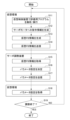
- FIG. 1 is a block diagram showing the configuration of a servo adjustment system according to a first embodiment. It is a flow chart which shows the procedure of the servo adjustment processing performed by the servo adjustment system concerning a 1st embodiment.
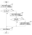
- 3 is a flowchart showing the procedure of feedback information generation processing.
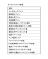
- FIG. 3 is a diagram showing servo parameter information.
- FIG. 3 is a diagram showing servo motor model information.
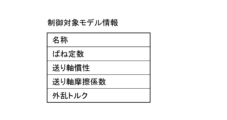
- FIG. 3 is a diagram showing controlled object model information.
- FIG. 3 is a diagram showing command information.
- FIG. 7 is a diagram showing servo motor model operation information in consideration of a motor friction coefficient.
- FIG. 7 is a diagram showing servo motor model operation information in consideration of a motor friction coefficient and a feed shaft friction coefficient.
- FIG. 3 is a flowchart illustrating a procedure for determining parameter settings. It is a figure showing an example of parameter adjustment.
- FIG. 2 is a block diagram showing the configuration of a servo adjustment system according to a second embodiment. It is a block diagram showing the composition of the servo adjustment system concerning a modification of a 2nd embodiment. It is a flowchart which shows the procedure of the servo adjustment process performed by the servo adjustment system based on 2nd Embodiment.
- 3 is a flowchart illustrating the procedure of a temporary determination process for parameter settings.
- FIG. 3 is a diagram showing an example of a parameter setting pattern.
- FIG. 3 is a diagram illustrating an example of parameter settings applied to multiple virtual environments.
- 3 is a flowchart illustrating a procedure for determining parameter settings. It is a figure which shows an example of a learning result.
- the servo adjustment system 1 according to the first embodiment is a system that adjusts control parameter setting information (hereinafter referred to as parameter setting information) of a servo motor controlled by a control device of an industrial machine such as a machine tool.
- FIG. 1 is a block diagram showing the configuration of a servo adjustment system 1 according to the first embodiment.
- the servo adjustment system 1 according to the first embodiment includes a servo adjustment device 10, a virtual control device 20, a servo motor model 30, and a controlled object model 40.
- the virtual control device 20, the servo motor model 30, and the controlled object model 40 constitute a virtual environment 50.
- the servo adjustment device 10 and the virtual control device 20 each include an arithmetic processing means such as a CPU (Central Processing Unit), an auxiliary storage means such as an HDD (Hard Disk Drive) or an SSD (Solid State Drive) that store various computer programs, and an arithmetic processing device.
- Main storage means such as RAM (Random Access Memory) for storing data temporarily required by the processing means to execute computer programs, operation means such as a keyboard for the operator to perform various operations, and various information for the operator.
- It is a computer configured with hardware such as display means such as a display that displays.
- These servo adjustment device 10, virtual control device 20, etc. are capable of transmitting and receiving various signals to and from each other, and the communication method thereof is not particularly limited.
- the servo adjustment device 10 and/or the virtual control device 20 are communicably connected to a numerical control device (CNC: Computerized Numerical Control), not shown, which corresponds to a control device of an industrial machine such as a machine tool, for example.
- CNC Computerized Numerical Control
- Servo parameter information necessary for servo adjustment in this embodiment which will be described later, is part of the CNC parameters stored in the numerical control device, and is acquired from the numerical control device. Further, the parameter setting information after servo adjustment in this embodiment is transmitted to this numerical control device and used for controlling the actual machine.
- the servo adjustment device 10 performs servo motor control parameter adjustment (hereinafter referred to as servo adjustment), such as gain filter adjustment, feedforward adjustment, acceleration/deceleration adjustment, etc. Specifically, the servo adjustment device 10 acquires virtual feedback information (hereinafter referred to as virtual FB information) obtained by executing the evaluation program multiple times based on different parameter setting information in the virtual control device 20 described below. Then, servo adjustment is performed by determining parameter setting information based on this information. The adjusted parameter setting information is sent to the virtual control device 20 and the numerical control device.
- servo adjustment servo motor control parameter adjustment
- the servo adjustment device 10 includes a virtual feedback information acquisition unit (not shown) that acquires the virtual FB information transmitted from the virtual control device 20, and a plurality of virtual FB information obtained by execution with different parameter setting information. and a parameter setting transmitter (not shown) that transmits the determined parameter setting information to the virtual control device 20 and the numerical control device.
- the virtual control device 20 virtually controls the servo motor model 30 by executing the evaluation program multiple times based on different parameter setting information and generating command information to be passed to the servo motor model 30, which will be described later. Further, thereby, the virtual control device 20 virtually drives a controlled object model 40 such as a machine tool, which will be described later.
- the virtual control device 20 transmits feedback information (hereinafter also referred to as FB information) obtained by virtually controlling the servo motor model 30 and the controlled object model 40 to the servo adjustment device 10. Note that the current parameter setting information transmitted from the servo adjustment device 10 is applied to the virtual control device 20.
- the evaluation program is a program that is created so that servo adjustment can be executed efficiently in a short time, separately from the actual machining program, which generally takes a long machining time.
- the evaluation program is, for example, a program that specifies the axial movement distance, feed rate, etc. according to various machining shapes such as circles, squares, squares with corners, etc.
- the servo motor model 30 is a model that virtualizes the operation and characteristics of a servo motor. That is, the virtual environment 50 of this embodiment includes a servo motor model 30 that virtualizes the operation of a servo motor of a machine tool or the like. Specifically, the servo motor model 30 is a virtual model that takes into consideration at least one of the undamped natural angular frequency, the damping coefficient, the preceding command time, the motor inertia, and the motor friction coefficient. As a result, it is possible to perform an operation simulation similar to that of the actual machine in the virtual environment 50, and it is possible to obtain virtual feedback information (hereinafter also referred to as virtual FB information) that is similar to that when operating the actual machine.
- virtual FB information virtual feedback information
- the controlled object model 40 is a model that virtualizes the operation and characteristics of an industrial machine such as a machine tool, for example. That is, the virtual environment 50 of this embodiment includes a controlled object model 40 that is a virtualized industrial machine such as a machine tool. Specifically, the controlled object model 40 is a model virtualized by taking into consideration at least one of a spring constant, feed shaft inertia, feed shaft friction coefficient, and disturbance torque. This allows the virtual environment 50 to perform an operation simulation that is closer to that of the actual machine, and it is possible to obtain virtual FB information that is closer to that when the actual machine is operated.
- the generation of command information for the servo motor model 30 in the virtual control device 20 and the generation of virtual FB information in the servo motor model 30 and the controlled object model 40 do not require real time. , it is possible to perform servo adjustment at high speed.
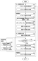
- FIG. 2 is a flowchart showing the procedure of the servo adjustment process executed by the servo adjustment system 1 according to the first embodiment. Execution of this servo adjustment process is started in response to, for example, an input operation from a user to the servo adjustment device 10.
- step S11 the virtual control device 20 analyzes and executes the evaluation program. More specifically, the virtual control device 20 executes the evaluation program based on the servo motor parameter setting information (hereinafter also simply referred to as parameter setting) currently applied to the virtual control device 20. After that, the process advances to step S12. Note that this parameter setting is adjusted and changed by the servo adjustment process according to this flow.
- parameter setting the servo motor parameter setting information
- step S12 the virtual control device 20 generates command information for the servo motor. Specifically, the virtual control device 20 analyzes and executes the evaluation program in step S11 described above, thereby generating command information for the servo motor. After that, the process advances to step S13.
- step S13 the virtual control device 20 generates virtual FB information. Specifically, the virtual control device 20 virtually controls and operates the servo motor model 30 and the controlled object model 40 based on the command information to the servo motor generated in step S12, thereby controlling the virtual FB information. generate. After that, the process advances to step S14. Note that this virtual FB information generation process will be described in detail later.
- step S14 the virtual control device 20 transmits the virtual FB information generated in step S13 described above to the servo adjustment device 10. After that, the process advances to step S15.
- step S15 the servo adjustment device 10 acquires the virtual FB information transmitted from the virtual control device 20. After that, the process advances to step S16.
- step S16 the servo adjustment device 10 determines parameter settings based on the acquired virtual FB information. After that, the process advances to step S17. Note that this parameter setting determination process will be described in detail later.
- step S17 the servo adjustment device 10 transmits the parameter settings determined in step S16 described above to the virtual control device 20. After that, the process advances to step S18.
- step S18 the virtual control device 20 acquires the parameter settings transmitted from the servo adjustment device 10.
- the newly acquired parameter settings this time are stored in the virtual control device 20 and applied to the next servo adjustment process. After that, the process advances to step S19.
- step S19 the servo adjustment device 10 determines whether the servo adjustment has been completed. Specifically, for example, the servo adjustment device 10 holds a list of adjustment parameters, and determines whether the servo adjustment has been completed based on whether adjustment of all parameters in this list has been completed. In addition, when adjusting each parameter, it is determined that the adjustment is not complete until the determination of parameter settings based on different virtual FB information is performed at least twice, that is, multiple times. It is determined that the adjustment has been completed when the value becomes 1% or less. However, it may be determined whether the servo adjustment is completed based on the user's judgment. If the determination is NO, the process returns to step S11, and if the determination is YES, the process ends.
- the parameter setting information is determined based on the virtual FB information obtained by analyzing and executing the evaluation program multiple times based on different parameter setting information in the virtual control device 20. and will be adjusted.
- FIG. 3 is a flowchart showing the procedure of virtual FB information generation processing.
- step S21 the virtual control device 20 adds servo parameter information to the virtual FB information generation element. That is, servo parameter information is added to the virtual FB information generation element regardless of the presence or absence of the servo motor model 30 and the controlled object model 40. After that, the process advances to step S22.
- the virtual FB information generation element is information necessary to generate virtual FB information in the virtual environment 50.
- the servo parameter information added as a virtual FB information generation element is the base of the virtual FB information generation element.
- This servo parameter information is included in CNC parameters stored in a numerical control device (CNC) (not shown) that is communicably connected to the servo adjustment system 1 of this embodiment, and is sent from the numerical control device. It is stored in the virtual control device 20.
- CNC numerical control device
- FIG. 4 is a diagram showing servo parameter information.
- the servo parameter information includes, for example, servo loop gain, speed integral gain, speed proportional gain, phase compensation gain, speed loop gain magnification during cutting, and gain magnification during high-speed HRV (High Response Vector) current control.
- speed integral gain shift amount, speed proportional gain shift amount, load inertia ratio, amplifier maximum torque, feedforward coefficient, feedforward coefficient when using EGB (electronic gearbox), speed feedforward coefficient, feedforward during cutting Examples include a coefficient, a speed feedforward coefficient during cutting, and the like.
- step S22 the virtual control device 20 determines the presence or absence of the servo motor model 30 in the virtual environment 50. Since the servo adjustment system 1 of this embodiment includes the servo motor model 30 in the virtual environment 50, this determination is YES and the process proceeds to step S23. On the other hand, if the configuration does not include the servo motor model 30, this determination is NO and the process proceeds to step S26, where the virtual control device 20 generates virtual FB information based on the virtual FB information generation element including servo parameter information. is generated, and this process ends.
- step S23 the virtual control device 20 adds servo motor model information to the virtual FB information generation element.
- the virtual FB information generation element includes servo parameter information and servo motor model information.
- the servo motor model information is not included in the CNC parameters, but is registered through a separate file input or input from a user's screen operation, etc., and is information stored in the virtual control device 20. It is.
- FIG. 5 is a diagram showing servo motor model information. As shown in FIG. 5, examples of the servo motor model information include an undamped natural angular frequency, a damping coefficient, a preceding command time, a motor inertia, a motor friction coefficient, and the like.
- step S24 the virtual control device 20 determines whether the controlled object model 40 exists in the virtual environment 50. Since the servo adjustment system 1 of this embodiment includes the controlled object model 40 in the virtual environment 50, this determination is YES and the process proceeds to step S25. On the other hand, if the controlled object model 40 is not provided, this determination becomes NO and the process proceeds to step S26, where the virtual control device 20 is virtualized based on the virtual FB information generation element including servo parameter information and servo motor model information. FB information is generated and this process ends. In this case, since the virtual FB information is generated based on the virtual FB information generation element including the servo motor model information, it is possible to generate virtual FB information that is closer to when the actual machine is operated.
- step S25 the virtual control device 20 adds controlled object model information to the virtual FB information generation element.
- the virtual FB information generation element includes servo parameter information, servo motor model information, and controlled object model information.
- the controlled object model information is not included in the CNC parameters, but is registered through a separate file input or input from a user's screen operation, etc., and is stored in the virtual control device 20. It is information.
- FIG. 6 is a diagram showing controlled object model information. As shown in FIG. 6, examples of the controlled object model information include a spring constant, feed shaft inertia, feed shaft friction coefficient, and disturbance torque.
- step S26 in which the virtual control device 20 generates virtual FB information based on the virtual FB information generation element including servo parameter information, servo motor model information, and controlled object model information. is generated, and this process ends.
- the virtual FB information is generated based on the virtual FB information generation element including the servo motor model information and the controlled object model information, it is possible to generate virtual FB information that is even closer to that when the actual machine is operated.
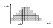
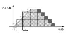
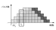
- the virtual FB information is generated by the virtual control device 20 calculating an error amount that is the difference (pulse number difference or time difference) between the servo motor model operation information and the command information.
- FIG. 7 is a diagram showing command information.
- FIG. 8 is a diagram showing servo motor model operation information in consideration of the motor friction coefficient.
- FIG. 9 is a diagram showing servo motor model operation information in consideration of the motor friction coefficient and the feed shaft friction coefficient.
- FIGS. 8 and 9 among the hatched areas that are different from the hatching of the command information pulses in FIG. The area represents an area where the number of pulses is greater than the number of pulses of the command information.
- the pulse of the servo motor model operation information that takes into account the motor friction coefficient included in the servo motor model information is delayed by a time ⁇ t a from the pulse of the command information shown in FIG. I understand. This is because when the motor friction coefficient of the servo motor model 30 is taken into consideration, a delay time difference ⁇ t a occurs between the command information and the time when the servo motor model 30 actually rotates/stops.
- the pulses of the servo motor model operation information which takes into account the feed shaft friction coefficient included in the controlled object model information in addition to the motor friction coefficient included in the servo motor model information, are shown in FIG. It can be seen that the pulse of the command information shown is further delayed by a time ⁇ t b which is larger than the time ⁇ t a . Taking into account the motor friction coefficient of the servo motor model 30 and the feed shaft friction coefficient of the controlled object model 40, this means that by the time the servo motor model 30 actually rotates/stops in response to the command information, This is because a delay time difference ⁇ t b occurs.
- the number of pulses of the command information is 4, while the number of pulses of the servo motor model operation information considering the motor friction coefficient of the servo motor model 30 is 3, and both It is possible to calculate the error amount 1, which is the difference between .
- the number of pulses of the servo motor model operation information considering the motor friction coefficient of the servo motor model 30 and the feed shaft friction coefficient of the controlled object model 40 is 2, and the error amount 2, which is the difference from the command information, is 2.
- the error amount which is the difference from the command information is 2.
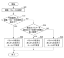
- FIG. 10 is a flowchart showing the procedure of the parameter setting determination process.
- step S31 the servo adjustment device 10 selects parameters to be servo adjusted (hereinafter referred to as adjustment parameters).
- the servo adjustment device 10 stores a list of adjustment parameters in advance, and automatically selects adjustment parameters from the stored list. Alternatively, the adjustment parameters may be selected according to input information from the user. After that, the process advances to step S32.
- the adjustment parameter means a parameter whose setting value is to be changed from the parameter setting determined by acquiring virtual FB information during the previous servo adjustment process.
- only one parameter is adjusted at the same time.
- the present invention is not limited to this, and it is also possible to adjust a plurality of parameters at the same time.
- the servo adjustment device 10 normally determines that the adjustment is completed according to a predetermined rule, such as a rule that continues adjustment until the adjustment amount of the adjustment parameter becomes 1% or less. It remains selected until a decision is made. That is, this parameter setting determination process is repeatedly executed until, for example, the adjustment amount of the adjustment parameter becomes 1% or less. However, it is also possible to forcibly interrupt the adjustment in accordance with input information from the user and to allow selection of the next adjustment parameter.
- a predetermined rule such as a rule that continues adjustment until the adjustment amount of the adjustment parameter becomes 1% or less. It remains selected until a decision is made. That is, this parameter setting determination process is repeatedly executed until, for example, the adjustment amount of the adjustment parameter becomes 1% or less.
- step S32 the servo adjustment device 10 determines whether or not the currently selected adjustment parameter is being changed for the first time. Specifically, the servo adjustment device 10 stores the number of times the parameter setting determination process has been executed for each adjustment parameter, and determines the parameter settings for the adjustment parameter selected in step S31 based on the stored information. It is determined whether or not the determination process is being performed for the first time. If this determination is YES, the process proceeds to step S33, and if NO, the process proceeds to step S34.
- step S33 since this is the first time that the adjustment parameter selected this time has been changed, the parameter settings are determined in accordance with predetermined rule 1, for example, rule 1 to change the adjustment parameter so that it is +10% from the initial value. do. After that, this process ends.
- step S34 since the adjustment parameter selected this time is not changed for the first time, the servo adjustment device 10 determines that the current virtual FB information generated and acquired by the virtual control device 20 is better than the previous parameter setting. Determine whether it is a result. For example, in this embodiment, if the error amount, which is the difference between the virtual FB information and the command information, is smaller than the previous parameter setting, it is determined that the result is good, and conversely, if it is large, the result is bad. It is determined that If this determination is YES, the process advances to step S35, and if NO, the process advances to step S36.
- step S35 since the current virtual FB information is a better result than the previous parameter setting, predetermined rule 2 is applied, for example, 80% of the previous adjustment amount in the same direction as the previous parameter setting. Parameter settings are determined according to rule 2, which adds the value of the previous value to the previous value. After that, this process ends.
- step S36 since the current virtual FB information is a bad result compared to the previous parameter setting, according to predetermined rule 3, for example, 80% of the previous adjustment amount is applied in the opposite direction to the previous parameter setting. % value is subtracted from the previous value (if it is the second time, it is a -8% subtraction since it is an 80% subtraction from the initial value +10%), the parameter settings are determined. After that, this process ends.
- FIG. 11 is a diagram showing an example of the parameter adjustment described above.
- the initial value of the selected adjustment parameter is, for example, 300.
- the adjustment parameter is changed for the first time, if the adjustment parameter is adjusted to be +10% of the initial value according to Rule 1, the adjusted value will be 330.
- the adjustment parameters are changed not for the first time but for example for the second time, and the current virtual FB information is a better result than the previous parameter settings, follow Rule 2 to change the previous parameter settings.
- the adjusted value becomes 354.
- the previous parameter setting If the adjustment is made in the opposite direction by subtracting 80% of the previous adjustment amount from the previous value, the adjusted value will be 306. In this way, the parameter setting determination process is repeatedly executed until, for example, the adjustment amount of the adjustment parameter becomes 1% or less.
- the servo motor model 30 is virtually controlled by executing an evaluation program based on the servo motor model 30 that virtualizes the operation of the servo motor and control parameter setting information.
- the configuration includes the following.
- the servo adjustment system 1 preferably further includes a controlled object model that is a virtualized industrial machine, and the servo adjustment device 10 has a servo motor model 30 that is virtually controlled by the virtual control device 20.
- the configuration is such that virtual FB information is acquired by driving the controlled object model 40.
- virtual FB information is generated from the virtual environment 50 using the servo motor model 30 including the operation and characteristics of the servo motor, and the controlled object model 40 including the operation and characteristics of the industrial machine.
- Servo adjustment can be automatically performed based on the servo adjustment, and parameter settings can be determined automatically and with high precision. Therefore, it is possible to generate virtual FB information that is closer to when the actual machine is operated, and it is possible to perform servo adjustment that is closer to when the actual machine is operated. Furthermore, compared to the case where the user decides the parameter settings, the burden on the user can be reduced and operational errors can be prevented.
- servo adjustment can be performed using the virtual environment 50, servo adjustment can be automatically performed in a short time by high-speed execution in the virtual environment 50. Therefore, it is possible to reduce equipment downtime due to no need for actual equipment, and it is also possible to perform servo adjustment work at the design stage.
- the movement of the tool tip point is simulated from the virtual FB information, that is, the operation of the servo motor model. This eliminates the need for additional devices such as acceleration sensors.
- the evaluation program is executed by the virtual control device 20, so by changing the evaluation program, virtual FB information for different command information can be easily obtained.
- the actual machining program or a part of it that the user uses for machining as an evaluation program, so there is no need to prepare separate axis movements for evaluation, and it is possible to use the actual machining program that you want to adjust. can be easily obtained.
- FIG. 12 is a block diagram showing the configuration of a servo adjustment system 1A according to the second embodiment. As shown in FIG. 12, the servo adjustment system 1A according to the second embodiment is different from the servo adjustment system 1 according to the first embodiment in that it includes a machine learning device 60 and a learning data memory 70, Other configurations are common to the first embodiment.
- the machine learning device 60 includes an arithmetic processing means such as a CPU, an auxiliary storage means such as an HDD or SSD that stores various computer programs, and an arithmetic processing means that executes a computer program. It consists of hardware such as main memory means such as RAM for storing temporarily required data, operating means such as a keyboard for the operator to perform various operations, and display means such as a display that displays various information to the operator. It is a computer that is The machine learning device 60 and the learning data memory 70 are capable of transmitting and receiving various signals to and from the servo adjustment device 10A and the virtual control device 20, and the communication method thereof is not particularly limited.
- the machine learning device 60 acquires virtual FB information from the virtual environment 50 via the servo adjustment device 10A, and performs servo adjustment by machine learning based on the acquired virtual FB information.
- the servo adjustment device 10 determines control parameter setting information according to predetermined rules based on virtual FB information obtained based on a plurality of different parameter settings.
- control parameter setting information is determined by machine learning using a machine learning device 60.
- the learning data memory 70 acquires and registers machine learning data including the learning results executed by this machine learning device 60.
- the learning results include, for example, a pass/fail judgment result according to the above-mentioned error amount, which is the difference between the virtual FB information and the command information to the servo motor model. The learning results will be detailed later.
- the machine learning data registered in the learning data memory 70 is shared between the virtual environment 50 and a real environment composed of servo motors, machine tools, numerical control devices, etc. (all not shown). This makes it possible to execute servo adjustment using more efficient machine learning, and to realize servo adjustment with higher accuracy and in a shorter time.
- the machine learning executed by the machine learning device 60 is not particularly limited, and examples include supervised learning, unsupervised learning, and reinforcement learning. Among these, reinforcement learning similar to the reinforcement learning described in JP-A-2018-180764, for example, can be preferably applied to the machine learning device 60 of this embodiment.
- the machine learning device 60 is configured to perform reinforcement learning on parameters (for example, parameters a i and b j (i, j ⁇ 0)) of control parameter setting information that is a target of servo adjustment, for example. Ru. More specifically, the machine learning device 60 uses the values of parameters a i and b j , virtual FB information obtained by the virtual control device 20 executing the evaluation program, and command information to the servo motor model 30 . etc. as a state s, and adjustment of parameters a i and b j related to this state s as an action a.
- parameters for example, parameters a i and b j (i, j ⁇ 0)
- FIG. 13 is a block diagram showing the configuration of a servo adjustment system 1B according to a modification of the second embodiment.
- the servo adjustment system 1B according to the modification of the second embodiment has a plurality of virtual environments 51, 52, ... 50n, compared to the servo adjustment system 1A according to the second embodiment.
- the difference is that the servo adjustment device 10B includes a plurality of environment management units 11, and the other configurations are the same as the second embodiment.
- Each of the plurality of virtual environments 51, 52, . . . 50n has the same configuration as the virtual environment 50 of the first embodiment and the second embodiment. That is, each of the plurality of virtual environments 51, 52, . . . 50n has the same configuration. Therefore, in addition to the virtual control devices 21, 22, . . . 20n all having the same configuration, the servo motor models 31, 32, . , 42, . . . 40n all have the same configuration. Therefore, by virtually operating the same machine tool model and servo motor model in multiple virtual environments, it is possible to acquire virtual FB information in parallel, and machine learning can be performed in parallel. This makes high-speed learning possible.
- the multiple environment management unit 11 included in the servo adjustment device 10B manages control parameter setting information applied to the multiple virtual environments 51, 52, . . . 50n. More specifically, the multiple environment management unit 11 manages parameter settings to be sent to the multiple virtual environments 51, 52, . . . 50n. That is, the multiple environment management unit 11 manages which parameter or which parameter setting pattern (described later) is to be executed in which virtual environment.
- FIG. 14 is a flowchart showing the procedure of the servo adjustment process executed by the servo adjustment system 1A according to the second embodiment. Execution of this servo adjustment process is started in response to, for example, an input operation from a user to the servo adjustment device 10A. Note that the servo adjustment process executed by the servo adjustment system 1B according to the modification of the second embodiment is also the same as the procedure shown in FIG. 14.
- step S51 the servo adjustment device 10A tentatively determines parameter settings. After that, the process advances to step S52. Note that this temporary determination process for parameter settings will be described in detail later.
- step S52 the servo adjustment device 10A transmits the parameter settings tentatively determined in step S51 described above to the virtual control device 20 of the virtual environment 50. After that, the process advances to step S53.
- step S53 the virtual control device 20 acquires the parameter settings tentatively determined and transmitted by the servo adjustment device 10A. After that, the process advances to step S54.
- Steps S54 to S58 correspond to steps S11 to S15 of the servo adjustment process according to the first embodiment, and similar processes are executed. That is, in this embodiment, the virtual FB information is generated by analyzing and executing the evaluation program in the virtual control device 20 based on the parameter settings tentatively determined by the servo adjustment device 10A. After that, the process advances to step S59.
- step S59 the machine learning device 60 performs machine learning based on virtual FB information based on a plurality of different control parameter setting information transmitted and acquired from the servo adjustment device 10A, and generates a learning result. After that, the process advances to step S60.
- step S60 the learning data memory 70 acquires the learning results obtained by machine learning in the machine learning device 60, and registers the acquired learning results in the data memory. After that, the process advances to step S61.
- step S61 the servo adjustment device 10A determines whether machine learning by the machine learning device 60 has been completed. If this determination is YES, the process advances to step S62, and if NO, the process returns to step S51.
- step S62 the servo adjustment device 10A determines parameter settings. After that, the process advances to step S63. Note that this parameter setting determination process will be described in detail later.
- Step S63 and step S64 correspond to step S17 and step S18 of the servo adjustment process according to the first embodiment, respectively, and similar processes are executed. After executing step S64, this process ends.
- FIG. 15 is a flowchart showing the procedure of the temporary determination process for parameter settings.
- step S71 the servo adjustment device 10A generates a target parameter setting pattern only for the first time. More specifically, determining one or more parameters for which optimal values are to be determined through machine learning by the machine learning device 60, that is, parameters to be servo adjusted (adjustment parameters), and setting parameters for executing the evaluation program. Generate a pattern. After that, the process advances to step S72.
- FIG. 16 is a diagram showing an example of a parameter setting pattern.
- a two-dimensional setting pattern is generated by defining a minimum value, a maximum value, and a step value for each of the two parameters X and Y.
- the parameter setting pattern shown in FIG. 16 is an example, and is not limited to a two-dimensional setting pattern, but may be a three-dimensional setting pattern. Note that this setting pattern is automatically determined by the servo adjustment device 10A. However, the user may be allowed to determine this parameter setting pattern.
- step S72 the servo adjustment device 10A determines whether there are multiple virtual environments.
- the virtual environment is one of the virtual environments 50, and since this determination is NO, the process advances to step S73.
- the servo adjustment system 1B according to the modification of the second embodiment there are a plurality of virtual environments such as virtual environments 51, 52, . . . 50n, and since this determination is YES, the process proceeds to step S74.
- step S73 since there is only one virtual environment as in the second embodiment, the servo adjustment device 10A sets the parameters to be applied to the virtual environment 50 based on the parameter setting pattern shown in FIG. 16, for example. is tentatively determined, and the process ends.
- step S74 since there is a plurality of virtual environments as in the modification of the second embodiment, the multiple environment management unit 11 included in the servo adjustment device 10B, for example, based on the parameter setting pattern shown in FIG. Parameter settings to be applied to each of the plurality of virtual environments 51, 52, . . . 50n are tentatively determined, and this processing is ended.
- FIG. 17 is a diagram showing an example of parameter settings applied to multiple virtual environments.
- the parameter settings shown in FIG. 17 are obtained by dividing the two-dimensional parameter setting pattern consisting of parameters X and Y shown in FIG. 16 into four parts and applying them to each of virtual environments 1 to 4. Since the servo adjustment system 1B according to the modification of the second embodiment has n virtual environments, the two-dimensional parameter setting pattern consisting of parameters X and Y shown in FIG. 16 is divided into n parts, and each virtual environment 51 , 52, . . . 50n.
- virtual FB information is acquired by allocating completely different patterns to each virtual environment, such as parameter X and parameter Y in the virtual environment 51, parameter N and parameter M in the virtual environment 52, etc.
- it may also be configured to perform machine learning.
- FIG. 18 is a flowchart showing the procedure of the parameter setting determination process.
- step S81 the servo adjustment device 10A determines the parameter settings that will yield the best judgment result from the learning results registered in the learning data memory 70.
- a criterion for the judgment for example, a pass/fail judgment result according to the error amount, which is the difference between the virtual FB information and the command information to the servo motor model, can be cited. After that, this process ends.
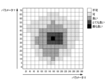
- FIG. 19 is a diagram showing an example of learning results.
- the specific pass/fail judgment results include, for example, "best”, “very good”, “good”, “acceptable”, and “unacceptable” for each parameter setting in descending order of error amount. ” are the judgment results.
- the best judgment result is the parameter settings of 160 for parameter X and 35 for parameter Y, so servo adjustment device 10A determines these parameter settings.
- the optimal value determined in the virtual environment does not necessarily match completely in the real environment. Therefore, it is preferable to perform machine learning again in a real environment, for example, limited to the range determined as "best” and "very good” as described above.
- the servo adjustment system 1A further includes a machine learning device 60 that performs machine learning on control parameter setting information using virtual FB information, and the servo adjustment device 10A uses the control parameter setting information based on the learning results by the machine learning device 60.
- the configuration is such that setting information is determined.
- servo adjustment using machine learning by the machine learning device 60 can be performed based on virtual FB information obtained by virtual control of the servo motor model 30 in the virtual environment 50. Therefore, according to this embodiment, it is possible to automatically perform servo adjustment with higher precision and in a shorter time.
- virtual control devices 21, 22, ... 20n servo motor models 31, 32, ... 30n, and controlled object models 41, 42, ... 40n
- the configuration includes a plurality of virtual environments 51, 52, . . . , 50n.
- the servo adjustment device 10B has a multiple environment management unit 11 that manages control parameter setting information applied to the plurality of virtual environments 51, 52, . , . . .50n is used for machine learning of control parameter setting information.
- machine learning based on virtual FB information can be executed at higher speed, and furthermore, it is possible to automatically execute servo adjustment with high precision and in a short time.
- a machine tool was used as an example of the industrial machine, but the present invention is not limited to this.
- the present disclosure is also applicable to other industrial machines such as robots with servo motors.
- the virtual environment 50 is configured to include the controlled object model 40, but the present invention is not limited to this.
- the present disclosure is applicable even to a virtual environment that does not include the controlled object model 40.
- the virtual environments 51, 52, . . . , 50n are all servo motor models 31, 32, .
- the configuration is as follows. It is not limited to this. A configuration may be adopted in which at least one of the plurality of virtual environments includes a servo motor model or a controlled object model, and another virtual environment does not include a servo motor model or a controlled object model.
Landscapes
- Engineering & Computer Science (AREA)
- Power Engineering (AREA)
- Artificial Intelligence (AREA)
- Evolutionary Computation (AREA)
- Feedback Control In General (AREA)
- Numerical Control (AREA)
- Control Of Electric Motors In General (AREA)
Abstract
Description
第1実施形態に係るサーボ調整システム1は、例えば工作機械等の産業機械の制御装置が制御するサーボモータの制御パラメータ設定情報(以下、パラメータ設定情報と言う。)を調整するシステムである。図1は、第1実施形態に係るサーボ調整システム1の構成を示すブロック図である。図1に示されるように、第1実施形態に係るサーボ調整システム1は、サーボ調整装置10と、仮想制御装置20と、サーボモータモデル30と、制御対象モデル40と、を備える。仮想制御装置20、サーボモータモデル30及び制御対象モデル40は、仮想環境50を構成する。
図12は、第2実施形態に係るサーボ調整システム1Aの構成を示すブロック図である。図12に示されるように、第2実施形態に係るサーボ調整システム1Aは、第1実施形態に係るサーボ調整システム1と比べて、機械学習装置60及び学習データメモリ70を備える点において相違し、その他の構成は第1実施形態と共通である。
10,10A,10B サーボ調整装置
11 複数環境管理部
20,21,22,20n 仮想制御装置
30,31,32,30n サーボモータモデル
40,41,42,40n 制御対象モデル
50,51,52,50n 仮想環境
60 機械学習装置
70 学習データメモリ
Claims (4)
- 産業機械の制御装置が制御するサーボモータの制御パラメータ設定情報を調整するサーボ調整システムであって、
前記サーボモータの動作を仮想化したサーボモータモデルと、
前記制御パラメータ設定情報に基づいて評価用プログラムを実行することにより前記サーボモータモデルを仮想的に制御する仮想制御装置と、
前記仮想制御装置で異なる前記制御パラメータ設定情報に基づいて前記評価用プログラムを複数回実行することで得られる仮想フィードバック情報に基づいて、前記制御パラメータ設定情報を決定するサーボ調整装置と、を備える、サーボ調整システム。 - 前記産業機械を仮想化した制御対象モデルをさらに備え、
前記サーボ調整装置は、前記仮想制御装置で仮想的に制御される前記サーボモータモデルが前記制御対象モデルを駆動させることで前記仮想フィードバック情報を取得する、請求項1に記載のサーボ調整システム。 - 前記仮想フィードバック情報を用いて前記制御パラメータ設定情報を機械学習する機械学習装置をさらに備え、
前記サーボ調整装置は、前記機械学習装置による学習結果に基づいて前記制御パラメータ設定情報を決定する、請求項1又は2に記載のサーボ調整システム。 - 前記仮想制御装置と、前記サーボモータモデルの少なくとも1つと、を有する仮想環境を複数備え、
前記サーボ調整装置は、前記複数の仮想環境に適用する前記制御パラメータ設定情報を管理する複数環境管理部を有し、
前記機械学習装置は、前記複数の仮想環境から得られる前記仮想フィードバック情報を用いて前記制御パラメータ設定情報を機械学習する、請求項3に記載のサーボ調整システム。
Priority Applications (4)
| Application Number | Priority Date | Filing Date | Title |
|---|---|---|---|
| PCT/JP2022/018671 WO2023209754A1 (ja) | 2022-04-25 | 2022-04-25 | サーボ調整システム |
| JP2024517613A JPWO2023209754A1 (ja) | 2022-04-25 | 2022-04-25 | |
| DE112022006672.5T DE112022006672T5 (de) | 2022-04-25 | 2022-04-25 | Servo-Einstellsystem |
| CN202280095032.7A CN119032506A (zh) | 2022-04-25 | 2022-04-25 | 伺服调整系统 |
Applications Claiming Priority (1)
| Application Number | Priority Date | Filing Date | Title |
|---|---|---|---|
| PCT/JP2022/018671 WO2023209754A1 (ja) | 2022-04-25 | 2022-04-25 | サーボ調整システム |
Publications (1)
| Publication Number | Publication Date |
|---|---|
| WO2023209754A1 true WO2023209754A1 (ja) | 2023-11-02 |
Family
ID=88518075
Family Applications (1)
| Application Number | Title | Priority Date | Filing Date |
|---|---|---|---|
| PCT/JP2022/018671 Ceased WO2023209754A1 (ja) | 2022-04-25 | 2022-04-25 | サーボ調整システム |
Country Status (4)
| Country | Link |
|---|---|
| JP (1) | JPWO2023209754A1 (ja) |
| CN (1) | CN119032506A (ja) |
| DE (1) | DE112022006672T5 (ja) |
| WO (1) | WO2023209754A1 (ja) |
Citations (1)
| Publication number | Priority date | Publication date | Assignee | Title |
|---|---|---|---|---|
| JP6961130B1 (ja) * | 2021-01-07 | 2021-11-05 | 三菱電機株式会社 | シミュレーションプログラム、シミュレーション装置、およびシミュレーション方法 |
Family Cites Families (4)
| Publication number | Priority date | Publication date | Assignee | Title |
|---|---|---|---|---|
| JP4283214B2 (ja) | 2004-12-16 | 2009-06-24 | ファナック株式会社 | 機械先端点の制御装置 |
| WO2013099032A1 (ja) * | 2011-12-28 | 2013-07-04 | 株式会社安川電機 | モーションコントローラ及びモータ制御システム |
| CN106489105B (zh) * | 2015-06-18 | 2018-06-22 | 三菱电机株式会社 | 控制参数调整装置 |
| JP6583070B2 (ja) | 2016-03-14 | 2019-10-02 | オムロン株式会社 | 設定支援装置、設定支援方法、情報処理プログラム、および記録媒体 |
-
2022
- 2022-04-25 DE DE112022006672.5T patent/DE112022006672T5/de active Pending
- 2022-04-25 CN CN202280095032.7A patent/CN119032506A/zh active Pending
- 2022-04-25 WO PCT/JP2022/018671 patent/WO2023209754A1/ja not_active Ceased
- 2022-04-25 JP JP2024517613A patent/JPWO2023209754A1/ja active Pending
Patent Citations (1)
| Publication number | Priority date | Publication date | Assignee | Title |
|---|---|---|---|---|
| JP6961130B1 (ja) * | 2021-01-07 | 2021-11-05 | 三菱電機株式会社 | シミュレーションプログラム、シミュレーション装置、およびシミュレーション方法 |
Also Published As
| Publication number | Publication date |
|---|---|
| JPWO2023209754A1 (ja) | 2023-11-02 |
| CN119032506A (zh) | 2024-11-26 |
| DE112022006672T5 (de) | 2025-01-02 |
Similar Documents
| Publication | Publication Date | Title |
|---|---|---|
| JP6474449B2 (ja) | 調整装置及び調整方法 | |
| US10824121B2 (en) | Machine learning device, servo motor controller, servo motor control system, and machine learning method | |
| Yeung et al. | Virtual CNC system. Part I. system architecture | |
| JP6843314B1 (ja) | 数値制御装置、数値制御方法および機械学習装置 | |
| CN111176114B (zh) | 输出装置、控制装置、以及评价函数和机器学习结果的输出方法 | |
| US11087509B2 (en) | Output device, control device, and evaluation function value output method | |
| JP6499720B2 (ja) | 機械学習装置、サーボ制御装置、サーボ制御システム、及び機械学習方法 | |
| JP6564432B2 (ja) | 機械学習装置、制御システム、制御装置、及び機械学習方法 | |
| JP6740279B2 (ja) | 調整装置及び調整方法 | |
| CN111103794B (zh) | 输出装置、控制装置、以及评价函数值的输出方法 | |
| JP7405537B2 (ja) | 機械学習装置、サーボ制御装置、サーボ制御システム及び機械学習方法 | |
| JP6961128B1 (ja) | シミュレーション装置、工作機械システム、シミュレーション方法および加工方法 | |
| CN111679632A (zh) | 切割控制的处理方法、装置、电子设备与存储介质 | |
| JP5362146B1 (ja) | 数値制御装置および数値制御システム | |
| JP2019053594A (ja) | 制御装置及び機械学習装置 | |
| WO2023209754A1 (ja) | サーボ調整システム | |
| JP6922333B2 (ja) | 情報処理装置、情報処理方法、および情報処理プログラム | |
| WO2009141006A1 (en) | A method and a system for controlling an industrial robot in accordance with a set of motion control parameters | |
| JP7518278B2 (ja) | 調整支援装置、制御システム及び調整支援方法 | |
| JP7786067B2 (ja) | 制御装置、制御方法およびプログラム | |
| JP7305061B2 (ja) | パラメータ調整装置およびパラメータ調整方法 | |
| US11022951B2 (en) | Information processing device and information processing method | |
| CN114114901A (zh) | 对机器的可移动的机器元件进行移动引导的方法和装置 | |
| JP6800384B1 (ja) | 位置決め制御装置および位置決め方法 | |
| JP7772829B2 (ja) | プログラム教示支援装置 |
Legal Events
| Date | Code | Title | Description |
|---|---|---|---|
| 121 | Ep: the epo has been informed by wipo that ep was designated in this application |
Ref document number: 22940035 Country of ref document: EP Kind code of ref document: A1 |
|
| WWE | Wipo information: entry into national phase |
Ref document number: 2024517613 Country of ref document: JP |
|
| WWE | Wipo information: entry into national phase |
Ref document number: 18854495 Country of ref document: US |
|
| WWE | Wipo information: entry into national phase |
Ref document number: 112022006672 Country of ref document: DE |
|
| WWE | Wipo information: entry into national phase |
Ref document number: 202280095032.7 Country of ref document: CN |
|
| 122 | Ep: pct application non-entry in european phase |
Ref document number: 22940035 Country of ref document: EP Kind code of ref document: A1 |