WO2023206302A1 - Appareil et procédé d'envoi de signal, ainsi qu'appareil et procédé de réception de signal - Google Patents
Appareil et procédé d'envoi de signal, ainsi qu'appareil et procédé de réception de signal Download PDFInfo
- Publication number
- WO2023206302A1 WO2023206302A1 PCT/CN2022/090095 CN2022090095W WO2023206302A1 WO 2023206302 A1 WO2023206302 A1 WO 2023206302A1 CN 2022090095 W CN2022090095 W CN 2022090095W WO 2023206302 A1 WO2023206302 A1 WO 2023206302A1
- Authority
- WO
- WIPO (PCT)
- Prior art keywords
- tci
- srs resource
- uplink
- resource set
- srs
- Prior art date
Links
- 238000000034 method Methods 0.000 title abstract description 75
- 230000005540 biological transmission Effects 0.000 claims description 134
- 101000946053 Homo sapiens Lysosomal-associated transmembrane protein 4A Proteins 0.000 claims description 33
- 102100034728 Lysosomal-associated transmembrane protein 4A Human genes 0.000 claims description 33
- 238000011144 upstream manufacturing Methods 0.000 claims description 29
- 230000000737 periodic effect Effects 0.000 claims description 13
- 239000011159 matrix material Substances 0.000 claims description 10
- 238000010586 diagram Methods 0.000 description 38
- 238000004891 communication Methods 0.000 description 29
- 230000015654 memory Effects 0.000 description 18
- 238000004590 computer program Methods 0.000 description 11
- 230000009471 action Effects 0.000 description 10
- 238000012986 modification Methods 0.000 description 10
- 230000004048 modification Effects 0.000 description 10
- 230000011664 signaling Effects 0.000 description 10
- 238000005516 engineering process Methods 0.000 description 9
- 230000006870 function Effects 0.000 description 7
- 230000004913 activation Effects 0.000 description 6
- 230000009849 deactivation Effects 0.000 description 4
- 238000007726 management method Methods 0.000 description 4
- 238000013507 mapping Methods 0.000 description 4
- 230000008569 process Effects 0.000 description 4
- 230000007774 longterm Effects 0.000 description 3
- 238000013475 authorization Methods 0.000 description 2
- 230000001413 cellular effect Effects 0.000 description 2
- 238000012545 processing Methods 0.000 description 2
- 230000008054 signal transmission Effects 0.000 description 2
- 238000001774 stimulated Raman spectroscopy Methods 0.000 description 2
- 101000741965 Homo sapiens Inactive tyrosine-protein kinase PRAG1 Proteins 0.000 description 1
- 102100038659 Inactive tyrosine-protein kinase PRAG1 Human genes 0.000 description 1
- 230000003213 activating effect Effects 0.000 description 1
- 230000002776 aggregation Effects 0.000 description 1
- 238000004220 aggregation Methods 0.000 description 1
- 230000004075 alteration Effects 0.000 description 1
- 230000009286 beneficial effect Effects 0.000 description 1
- 238000013461 design Methods 0.000 description 1
- 230000010365 information processing Effects 0.000 description 1
- 238000005259 measurement Methods 0.000 description 1
- 230000007246 mechanism Effects 0.000 description 1
- 238000012544 monitoring process Methods 0.000 description 1
- 230000003287 optical effect Effects 0.000 description 1
- 230000008520 organization Effects 0.000 description 1
- 238000013468 resource allocation Methods 0.000 description 1
- 239000013589 supplement Substances 0.000 description 1
- 230000002123 temporal effect Effects 0.000 description 1
Images


Classifications
-
- H—ELECTRICITY
- H04—ELECTRIC COMMUNICATION TECHNIQUE
- H04W—WIRELESS COMMUNICATION NETWORKS
- H04W72/00—Local resource management
- H04W72/04—Wireless resource allocation
Definitions
- the embodiments of this application relate to the field of communication technology.
- unified TCI in Rel-17 is mainly designed for sTRP (single transmission and reception point) scenarios.
- TRP multiple transmission and reception point
- mTRP transmission includes mTRP transmission based on single DCI (single Downlink Control Information, sDCI) and mTRP transmission based on multiple DCI (multiple DCI, mDCI).
- the network device uses RRC signaling to configure M (M ⁇ 1) TCI states (TCI states) for the terminal device, and uses MAC CE to configure M TCI states for the terminal device.
- N (1 ⁇ N ⁇ M) TCI states are activated in the state, and DCI is used to indicate L (1 ⁇ L ⁇ N) TCI states among the N TCI states.
- a TCI state (TCI for short) can include or correspond to one or two source reference signals (source RS, source Reference Signal).
- the source reference signal can provide quasi co-location (QCL, Quasi Co-Location) information for downlink reception, which is called the downlink source reference signal.
- the source reference signal can provide a reference for the uplink transmission spatial filter (UL TX spatial filter, uplink transmission spatial filter) and is called the uplink source reference signal.
- the source reference signal can provide beam information for the destination channel/signal.
- the beam used by the terminal device to receive the destination channel/signal is the same as the beam used to receive the downlink source reference signal.
- the beam used by the terminal equipment to transmit the destination channel/signal is the same as the beam used to transmit the uplink source reference signal.
- the beam used by the terminal equipment to transmit the destination channel/signal has reciprocity with the beam used to receive the downlink source reference signal, that is, beams with opposite directions are used.
- TCI status includes joint TCI status, downlink TCI status and uplink TCI status.
- the source reference signal included in the downlink TCI state is the downlink source reference signal
- the source reference signal included in the uplink TCI state is the uplink source reference signal
- the source reference signal included in the joint TCI state is both the downlink source reference signal and the uplink source reference signal.
- the joint TCI state affects both the downlink beam (receive beam) and the uplink beam (transmit beam). In other words, the downlink beam and the uplink beam use the same beam, but the beam directions are opposite, that is, there is reciprocity between the uplink and downlink beams.
- the downlink TCI status only affects the downlink beam.
- the uplink TCI status only affects the uplink beam.
- the uplink beam is also called the uplink transmit spatial filter.
- the TCI field can indicate the joint TCI status (joint DL/UL TCI), or the TCI field can indicate the independent TCI status (separate DL/UL TCI), that is, indicate the downlink TCI status and/or the uplink TCI status, indicate the joint TCI status or indicate independent TCI status can be configured through RRC signaling.
- one TCI field indicates a combined TCI state (equivalent to indicating both a downlink TCI state and an uplink TCI state).
- one TCI field indicates A downlink TCI status either indicates an uplink TCI status, or indicates a downlink TCI status and an uplink TCI status.
- the unified TCI of mTRP needs to be able to indicate the TCI status of multiple TRPs (two or more TRPs) (multiple TCI statuses), and also be able to indicate the TCI status of one TRP (one TCI status). instruct.
- the terminal device may have ambiguity about which TRP to perform uplink transmission (that is, which SRS resource set is based on which transmission parameters are determined), resulting in the failure of uplink transmission, thereby affecting The overall performance of the system.
- embodiments of the present application provide a signal sending and signal receiving method and device.
- TRP time to use uplink transmission parameters
- SRS resource set is based on which transmission parameters are determined
- a signal sending method in which a terminal device is configured with multiple SRS resource sets, and the method includes:
- the terminal device receives TCI status indication information, and the TCI status indication information indicates at least one TCI status;
- Uplink signaling is performed using parameters associated with the associated SRS resource set and/or the TCI state.
- a signal receiving method is provided, applied to network equipment, and the method includes:
- the TCI status indication information indicating at least one TCI status; wherein at least one SRS resource set among the plurality of SRS resource sets is associated with the TCI status;
- a signal sending device wherein the signal sending device includes:
- a receiving unit that receives TCI status indication information, where the TCI status indication information indicates at least one TCI status
- a determining unit that determines an SRS resource set associated with the TCI state among multiple configured SRS resource sets
- a sending unit that uses parameters associated with the associated SRS resource set and/or the TCI state to perform uplink transmission.
- a signal receiving device wherein the signal receiving device includes:
- Configuration unit which configures multiple SRS resource collections
- a sending unit that sends TCI status indication information, the TCI status indication information indicating at least one TCI status
- a receiving unit that receives an uplink signal sent by a terminal device, wherein the terminal device sends the uplink signal using parameters associated with an associated SRS resource set and/or the TCI state.
- the terminal device receives TCI status indication information, which indicates at least one TCI status; determines the SRS resource set associated with the TCI status among multiple SRS resource sets; uses The associated SRS resource set and/or the parameters associated with the TCI status are sent for uplink signaling.
- TCI status indication information which indicates at least one TCI status
- uses The associated SRS resource set and/or the parameters associated with the TCI status are sent for uplink signaling.
- the terminal device performs uplink transmission by using appropriate uplink transmission parameters, thereby ensuring the throughput or reliability of the uplink transmission.
- Figure 1 is a schematic diagram of a communication system according to an embodiment of the present application.
- Figure 2 is a schematic diagram of a scenario according to an embodiment of the present application.
- Figure 3 is a schematic diagram of a signal sending method according to an embodiment of the present application.
- Figure 4 is a schematic diagram of a terminal device transmitting uplink signals according to an embodiment of the present application.
- Figure 5 is a schematic diagram of determining an associated SRS resource set according to an embodiment of the present application.
- Figure 6 is another schematic diagram of determining an associated SRS resource set according to an embodiment of the present application.
- Figure 7 is a schematic diagram of scheduling or not scheduling downlink allocation/uplink allocation according to an embodiment of the present application.
- Figure 8 is a schematic diagram of determining a set of associated SRS resources based on an uplink source reference signal according to an embodiment of the present application
- Figure 9 is a schematic diagram indicating an associated SRS resource set according to an embodiment of the present application.
- Figure 10 is a schematic diagram of the unified TCI state activated/deactivated through MAC CE according to the embodiment of the present application.
- Figure 11 is another schematic diagram of the activation/deactivation of the unified TCI state through MAC CE according to an embodiment of the present application
- Figure 12 is a schematic diagram of PUSCH repeated transmission according to the embodiment of the present application.
- Figure 13 is another schematic diagram of PUSCH repeated transmission according to the embodiment of the present application.
- Figure 14 is a schematic diagram of a signal receiving method according to an embodiment of the present application.
- Figure 15 is a schematic diagram of a signal sending device according to an embodiment of the present application.
- Figure 16 is a schematic diagram of a signal receiving device according to an embodiment of the present application.
- Figure 17 is a schematic diagram of the structure of a network device according to an embodiment of the present application.
- Figure 18 is a schematic diagram of a terminal device according to an embodiment of the present application.
- the terms “first”, “second”, etc. are used to distinguish different elements from the title, but do not indicate the spatial arrangement or temporal order of these elements, and these elements should not be used by these terms. restricted.
- the term “and/or” includes any and all combinations of one or more of the associated listed terms.
- the terms “comprises,” “includes,” “having” and the like refer to the presence of stated features, elements, elements or components but do not exclude the presence or addition of one or more other features, elements, elements or components.
- the term “communication network” or “wireless communication network” may refer to a network that complies with any of the following communication standards, such as Long Term Evolution (LTE, Long Term Evolution), Long Term Evolution Enhanced (LTE-A, LTE- Advanced), Wideband Code Division Multiple Access (WCDMA, Wideband Code Division Multiple Access), High-Speed Packet Access (HSPA, High-Speed Packet Access), etc.
- LTE Long Term Evolution
- LTE-A Long Term Evolution Enhanced
- LTE-A Long Term Evolution Enhanced
- WCDMA Wideband Code Division Multiple Access
- High-Speed Packet Access High-Speed Packet Access
- communication between devices in the communication system can be carried out according to any stage of communication protocols, which may include but are not limited to the following communication protocols: 1G (generation), 2G, 2.5G, 2.75G, 3G, 4G, 4.5G and 5G. , New Wireless (NR, New Radio), etc., and/or other communication protocols currently known or to be developed in the future.
- Network device refers to a device in a communication system that connects a terminal device to the communication network and provides services to the terminal device.
- Network equipment may include but is not limited to the following equipment: base station (BS, Base Station), access point (AP, Access Point), transmission and reception point (TRP, Transmission Reception Point), broadcast transmitter, mobile management entity (MME, Mobile Management Entity), gateway, server, wireless network controller (RNC, Radio Network Controller), base station controller (BSC, Base Station Controller), etc.
- the base station may include but is not limited to: Node B (NodeB or NB), evolved Node B (eNodeB or eNB) and 5G base station (gNB), etc.
- it may also include remote radio head (RRH, Remote Radio Head) , Remote Radio Unit (RRU, Remote Radio Unit), relay or low-power node (such as femeto, pico, etc.).
- RRH Remote Radio Head
- RRU Remote Radio Unit
- relay or low-power node such as femeto, pico, etc.
- base station may include some or all of their functions, each of which may provide communications coverage to a specific geographic area.
- the term "cell” may refer to a base station and/or its coverage area, depending on the context in which the term is used.
- the term "user equipment” (UE, User Equipment) or “terminal equipment” (TE, Terminal Equipment or Terminal Device) refers to a device that accesses a communication network through a network device and receives network services.
- Terminal equipment can be fixed or mobile, and can also be called mobile station (MS, Mobile Station), terminal, subscriber station (SS, Subscriber Station), access terminal (AT, Access Terminal), station, etc.
- the terminal equipment may include but is not limited to the following equipment: cellular phone (Cellular Phone), personal digital assistant (PDA, Personal Digital Assistant), wireless modem, wireless communication equipment, handheld device, machine-type communication equipment, laptop computer, Cordless phones, smartphones, smart watches, digital cameras, and more.
- cellular phone Cellular Phone
- PDA Personal Digital Assistant
- wireless modem wireless communication equipment
- handheld device machine-type communication equipment
- laptop computer Cordless phones
- Cordless phones smartphones, smart watches, digital cameras, and more.
- the terminal device can also be a machine or device for monitoring or measuring.
- the terminal device can include but is not limited to: Machine Type Communication (MTC) terminals, Vehicle communication terminals, device-to-device (D2D, Device to Device) terminals, machine-to-machine (M2M, Machine to Machine) terminals, etc.
- MTC Machine Type Communication
- D2D Device to Device
- M2M Machine to Machine
- network side refers to one side of the network, which may be a certain base station or may include one or more network devices as above.
- user side or “terminal side” or “terminal device side” refers to the side of the user or terminal, which may be a certain UE or may include one or more terminal devices as above.
- device can refer to network equipment or terminal equipment.
- FIG 1 is a schematic diagram of a communication system according to an embodiment of the present application, schematically illustrating a terminal device and a network device as an example.
- the communication system 100 may include a first TRP 101, a second TRP 102 and a terminal device 103. .
- the first TRP101 and the second TRP102 may be network devices.
- Figure 1 only takes two network devices and one terminal device as an example for illustration, but the embodiment of the present application is not limited thereto.
- existing services or services that may be implemented in the future can be transmitted between the first TRP 101, the second TRP 102, and the terminal device 103.
- these services may include but are not limited to: enhanced mobile broadband (eMBB, enhanced Mobile Broadband), massive machine type communication (mMTC, massive Machine Type Communication) and high-reliability and low-latency communication (URLLC, Ultra-Reliable and Low -Latency Communication), etc.
- eMBB enhanced mobile broadband
- mMTC massive Machine Type Communication
- URLLC Ultra-Reliable and Low -Latency Communication
- mTRP transmission includes mTRP transmission based on sDCI (single DCI) and mTRP transmission based on mDCI (multiple DCI).
- sDCI mTRP single DCI
- mDCI mTRP multiple DCI
- one DCI schedules the uplink and downlink transmission of two TRPs, which is more suitable for ideal situations where the backhaul between TRPs is ideal.
- mDCI mTRP two TRPs use two DCIs to schedule the uplink and downlink transmission of their respective TRPs respectively, which is more suitable for situations where the backhaul between TRPs is not ideal.
- unified TCI when unified TCI is used to indicate the TCI status of multiple TRPs, unified TCI can also indicate the TCI status of one TRP.
- the terminal device 103 sends PUSCH in a PUSCH repetition (PUSCH repetition) manner. For example, transmit to the first TRP 101 in time slot 1, transmit to the second TRP 102 in time slot 2, and so on.
- PUSCH repetition PUSCH repetition
- the terminal device is configured with two SRS resource sets (SRS resource sets).
- the terminal device 103 is configured with the first SRS resource set (1st SRS resource set) corresponding to the first TRP 101; for the terminal device 103 Configure the second SRS resource set (2nd SRS resource set) corresponding to the second TRP 102.
- the terminal equipment may send PUSCH to the first TRP101 and/or the second TRP102 based on different precoding matrices, SRI (SRS resource indicator), power control parameters and other transmission parameters. .
- the terminal device obtains transmission parameters for the first TRP101 and the second TRP102 based on the first SRS resource set and the second SRS resource set.
- the terminal device needs to know the mapping relationship between PUSCH repetition and SRS resource set, that is, it needs to know which SRS resource set each PUSCH repetition should be sent based on.
- the TCI field can indicate two upstream TCI states or joint TCI states, or can indicate one upstream TCI state or joint TCI state.
- the terminal device cannot know which SRS resource set should be used for transmission when performing uplink transmission.
- the terminal device Since the SRS resource is associated with the SRS resource set, the terminal device cannot know which SRS resource is based on which the transmission is based. Since the antennas, precoding matrices, number of layers, power control parameters and other information used for uplink transmission are all determined based on the SRS resource set or SRS resources, if the terminal device cannot know which SRS resource is used for transmission, it will cause harm to the uplink transmission. Data rate (throughput) or reliability. This is schematically explained below through the accompanying drawings.
- FIG. 2 is a schematic diagram of a scenario according to an embodiment of the present application.
- the terminal device 103 is configured with two SRS resource sets, and, at time T, the terminal device 103 is instructed to have a TCI state.
- the terminal device 103 can know the corresponding uplink transmission beam based on the indicated TCI status, the terminal device 103 does not know which TRP (SRS resource set) the uplink beam corresponds to, and the terminal device 103 indicates the SRS resources used by the two TRPs. (SRI, SRS resource indicator) and coding matrix indicator (PMI, Precoding Matrix Indicator) are different. If the terminal equipment 103 uses the SRI and PMI that should be used by the first TRP101 to send uplink signals to the second TRP102, it will cause the uplink Signal sending fails and vice versa.
- SRI SRS resource indicator
- PMI Precoding Matrix Indicator
- embodiments of the present application provide a signal sending method, a signal receiving method and a device when DCI is used to indicate a unified TCI in a multi-TRP scenario.
- the embodiment of the present application provides a signal sending method, which is applied on the terminal device side.
- the terminal device is configured with multiple SRS resource sets.
- Figure 3 is a schematic diagram of a signal sending method according to an embodiment of the present application. As shown in Figure 3, the method includes:
- the terminal device receives TCI status indication information, which indicates at least one TCI status;
- TRP and “SRS resource set” may be used interchangeably.
- TRP and “CSI-RS resource set” are interchangeable.
- corresponding can be replaced with each other, and “uplink TCI status” and “joint TCI status” can be replaced with each other.
- PUSCH PUSCH transmission
- PUSCH transmission may be interchangeable; the embodiments of the present application are not limited thereto.
- the terminal device receives TCI status indication information, and the TCI status indication information indicates at least one TCI status; determines an SRS resource set associated with the TCI status among multiple SRS resource sets; and uses the SRS resource set associated with the TCI status and/or Or the parameters associated with the TCI status are used to send uplink signals.
- the terminal device can avoid ambiguity about which TRP uplink transmission parameter to use, and the terminal device can ensure the throughput or reliability of the uplink transmission by using appropriate uplink transmission parameters for uplink transmission.
- the following describes the indication of at least one TCI status in 301.
- the TCI status indication information is carried by a TCI field in the first DCI format.
- the first DCI format is DCI format 1_1 or DCI format 1_2.
- the TCI status indication information indicates the uplink TCI status and/or the downlink TCI status; or, the TCI status indication information indicates a joint TCI status used to indicate the uplink TCI status and the downlink TCI status.
- the TCI status indication information indicates at least one of the following TCI statuses:
- One downlink TCI status and one uplink TCI status are One downlink TCI status and one uplink TCI status;
- one or more TCI states are indicated through a transmission configuration indication (TCI) field of DCI format 1_1 or DCI format 1_2.
- TCI format 1_1 or DCI format 1_2 can schedule downlink data, which is called DCI format 1_1/1_2with DL assignment, or it can not schedule downlink data, which is called DCI format 1_1/1_2without DL assignment (specifically indicating unified TCI).
- the terminal device determines the set of SRS resources associated with the TCI state under at least one of the following conditions:
- the terminal device is configured with two SRS resource sets.
- the network device is configured through RRC signaling;
- DCI format 1_1/1_2with/without DL assignment indicates Transmission Configuration Indication (TCI) status indication information, which indicates an uplink TCI state (UL-TCIState) or joint TCI state (DLorJoint-TCIState);
- TCI Transmission Configuration Indication
- the terminal device is configured with two SRS resource sets.
- a set of SRS resources is associated with at least one of the following signals/channels:
- PUSCH Physical uplink shared channel
- dynamic grant for example, PUSCH scheduled based on DCI format 0_1 or DCI format 0_2; in some implementations, PUSCH transmission based on dynamic grant is based on sDCI (single DCI) Multi-TRP (mTRP, multiple TRP) PUSCH transmission, for example, scheduling PUSCH transmission for multiple TRPs through a single DCI;
- sDCI single DCI
- mTRP multiple TRP
- the uplink transmission authorization is provided by the resource management layer (RRC), and the terminal device stores the configuration and uses it as the authorized configuration;
- RRC resource management layer
- the uplink transmission grant is provided by the resource management layer (RRC), and the configuration is activated or deactivated according to the physical downlink control channel (PDCCH).
- RRC resource management layer
- PDCH physical downlink control channel
- Periodic SRS Periodic SRS (Periodic SRS);
- SRS Semi-persistent sounding reference signal
- Aperiodic SRS (Aperiodic SRS);
- PUCCH Physical uplink control channel
- dynamic grant-based PUSCH transmission includes initial transmission and retransmission of PUSCH not based on Type 1/Type 2 configured grant scheduled through DCI format 0_1 or DCI format 0_2, and through DCI format 0_1 or DCI format 0_2 scheduled retransmission of PUSCH based on Type 1/Type 2 configured grant.
- Type 1/Type 2 configured grant scheduled through DCI format 0_1 or DCI format 0_2
- DCI format 0_1 or DCI format 0_2 scheduled retransmission of PUSCH based on Type 1/Type 2 configured grant.
- the following is an example of how to determine the SRS resource set associated with at least one TCI state indicated by the TCI state indication information in step 302.
- the associated SRS resource set is a predetermined SRS resource set among multiple SRS resource sets.
- the associated SRS resource set is a first SRS resource set among the multiple SRS resource sets.
- the SRS resource set The index of the collection is 0, for example.
- the associated set of SRS resources is determined based on an indication of a second DCI format that indicates or activates at least one of the following:
- PUSCH Physical uplink shared channel
- PUCCH Physical uplink control channel
- SRS Semi-persistent sounding reference signal
- the terminal device within the action time of an uplink TCI state or a combined TCI state, receives the second DCI format, and determines a set of SRS resources associated with an uplink TCI state or a combined TCI state based on the second DCI format.
- the second DCI format may be DCI format 0_1 (DCI format 0_1) or DCI format 0_2 (DCI format 0_2), or may also be called the second DCI format uplink transmission authorization.
- the associated SRS resource set is indicated by the SRS resource set indicator field in DCI format 0_1 (DCI format 0_1) or DCI format 0_2 (DCI format 0_2), or by an SRS request. ) field indication.
- the SRS resource set indication field or SRS request field in DCI format 0_1 or DCI format 0_2 indicates an uplink TCI status or a joint TCI status.
- DCI format 0_1 or DCI format 0_2 is within the action time of an uplink TCI state or a combined TCI state.
- the second DCI format may be DCI format 1_1 (DCI format 1_1) or DCI format 1_2 (DCI format 1_2).
- the associated set of SRS resources is indicated by the SRS request field in DCI format 1_1 or DCI format 1_2.
- the second DCI format also schedules the transmission of uplink data when indicating the associated SRS resource set, which is called DCI format 0_1/0_2 with UL allocation; or the second DCI format indicates the associated SRS In the case of resource aggregation, uplink data transmission is not scheduled, which is called DCI format 0_1/0_2 without UL allocation. That is to say, the second DCI format may be a DCI that multiplexes scheduled uplink data, or may be a DCI that specifically indicates an associated SRS resource set.
- the associated set of SRS resources is determined based on the reference signal. For example, the associated SRS resource set is determined based on the reference signal in the uplink TCI state or the joint TCI state; or the associated SRS resource set is determined based on the reference signal in the PUCCH spatial relationship information (spatial relation info).
- the associated set of SRS resources is determined based on an indication of a first DCI format, which may be DCI format 1_1 (DCI format 1_1) or DCI format 1_2 (DCI format 1_2).
- a first DCI format which may be DCI format 1_1 (DCI format 1_1) or DCI format 1_2 (DCI format 1_2).
- the associated SRS resource set is indicated by an unused field of DCI format 1_1 or DCI format 1_2; and/or the associated SRS resource set is indicated by a new field of DCI format 1_1 or DCI format 1_2; and/or the associated SRS
- the collection of resources is indicated by the TCI field of DCI format 1_1 or DCI format 1_2.
- the above methods for indicating the associated SRS resource set can be used jointly, for example, by jointly indicating the associated SRS resource set through the first DCI format and the second DCI format, for example, through the SRS resource set in the second DCI format.
- At least one of the indication field, the SRS request field, the PUCCH resource indication field, and the TCI field, the unused field, and the new field of the first DCI format jointly indicate the SRS resource set.
- the associated SRS resource set is determined based on at least one of the SRS resource set indication field, the SRS request field, and the PUCCH resource indication field. Same as the associated set of SRS resources indicated by the TCI field.
- the associated SRS resource set may be determined in at least one of the following ways: determined based on a predetermined SRS resource set among multiple SRS resource sets, determined based on an indication of the second DCI format, based on The reference signal is determined.
- the associated SRS resource set is indicated by the SRS resource set indication field or the SRS request field in the most recently received second DCI format; after determining If the associated SRS resource set has not received the second DCI format before, the associated SRS resource set is the first SRS resource set among the multiple SRS resource sets.
- the associated SRS resource set may be determined in at least one of the following ways: determined based on an indication of the second DCI format, determined based on a reference signal, or determined based on the first DCI format.
- this application does not enumerate other methods of jointly determining associated SRS resource sets.
- step 303 The following describes the uplink signal transmission in step 303.
- the terminal device determines the SRS resource set associated with the TCI state among multiple SRS resource sets, it needs to further determine parameters associated with the associated SRS resource set and/or the TCI state.
- the parameters associated with the associated SRS resource set include at least one of the following parameters: SRS resource indicator (SRI, SRS resource indicator), Precoding Matrix Indicator (PMI, Precoding Matrix Indicator), number of layers, antenna number, antenna index, and power control parameters; in some embodiments, the parameters associated with the TCI state include power control parameters.
- SRI SRS resource indicator
- PMI Precoding Matrix Indicator
- number of layers antenna number, antenna index, and power control parameters
- the parameters associated with the TCI state include power control parameters.
- the power control parameters include target received power (P0), path loss compensation factor (alpha), path loss reference signal (PL-RS, Pathloss-Reference Signal) and closed loop index (closed loop index). At least one.
- the following is an example of a terminal device using parameters associated with an associated SRS resource set or a TCI state to transmit uplink signals.
- Figure 4 is a schematic diagram of a terminal device transmitting uplink signals according to an embodiment of the present application.
- the network device configures the first SRS resource set (1st SRS resource set) corresponding to the first TRP101 for the terminal device 103; and configures the second TRP102 for the terminal device 103.
- the second SRS resource set (2nd SRS resource set).
- the number of antennas, antenna index and power control parameters are independent.
- the associated SRI, PMI, and layer number are respectively configured for the first SRS resource set (1st SRS resource set) and the second SRS resource set (2nd SRS resource set). , number of antennas, antenna index and power control parameters.
- the "srs-ResourceIndicator” field indicates the SRI
- the "precodingAndNumberOfLayers” field indicates the PMI and number of layers
- the "p0-PUSCH-Alpha” field indicates the target received power (P0) and path loss compensation.
- Factor (alpha) indicating the closed loop index (closed loop index) through the "powerControlLoopToUse” field
- PL-RS path loss reference signal
- each parameter configured for the first SRS resource set (1st SRS resource set) is indicated by the following information:
- Each parameter configured for the second SRS resource set (2nd SRS resource set) is indicated by the following information:
- the terminal device determines parameters associated with different SRS resource sets based on the above-mentioned RRC configuration; further, the terminal device determines the PUSCH based on Type 1 configured grant and the first SRS resource set (1st SRS resource set); thus, the terminal device sends the PUSCH of Type 1 configured grant using the above parameters associated with the first SRS resource set (1st SRS resource set).
- the terminal device 103 uses the first parameter and the second parameter to send the PUSCH.
- the first parameter is determined based on a specific SRS resource set, and the first parameter includes at least one of SRI, PMI, and layer number.
- the second parameter is determined based on an uplink TCI state or a joint TCI state indicated by DCI format 1_1 or DCI format 1_2, and the second parameter includes a power control parameter.
- the terminal device uses the SRI, PMI, and layer number associated with the first SRS resource set (1st SRS resource set), that is, the first parameter, and the association method is as described above.
- the TCI field of DCI format 1_1 or DCI format 1_2 indicates an uplink TCI state or a joint TCI state, which includes or is associated with a path loss reference signal (PL-RS), a target received power (P0 ), path loss compensation factor (alpha) and closed loop index (closedLoopIndex), whereby the terminal device can determine the power control parameter, that is, the second parameter, based on the TCI state.
- the terminal device determines the first parameter and the second parameter, and then sends the PUSCH based on the Type 1 configured grant based on the first parameter and the second parameter.
- the SRS resource set is determined according to the above implementation.
- the TCI status indication information indicates an uplink TCI status or a joint TCI status
- Figure 5 illustrates this schematically.
- Figure 5 is a schematic diagram of determining an associated SRS resource set according to an embodiment of the present application.
- the TCI field of the first DCI format indicates 2 uplink TCI states at time T1. After a period of time, such as after time T2, the TCI field indicates 1 uplink TCI state. That is to say, the TCI field indicates 1 After an uplink TCI state, the terminal device needs to determine the SRS resource set associated with the uplink TCI state.
- the action time of the indicated TCI state begins a period of time after the DCI is sent, for example, time T1, T2 are the times of indicating the TCI state, and ⁇ is the action of the TCI state.
- the terminal device determines an SRS resource set associated with the uplink TCI state based on the above embodiment.
- the TCI indicated by the first DCI format may be a case where downlink TCI and uplink TCI are indicated separately (ie, separate DL/UL TCI).
- the value of the "unifiedtci-StateType" field in the RRC configuration is SeparateULDL.
- the TCI indicated by the first DCI format may be a case where downlink TCI and uplink TCI are jointly indicated (ie, joint DL/UL TCI).
- the "unifiedtci-StateType" field in the RRC configuration is JointULDL.
- the associated SRS resource set is a first SRS resource set of multiple SRS resource sets.
- the terminal device is configured with two SRS resource sets.
- the number of uplink TCI states indicated by the TCI field is 1 (similar to the above implementation)
- PUSCH based on Type 1 configured grant is considered to be the same as the first SRS. Resource collection association.
- DCI format 0_0 schedules PUSCH transmission based on dynamic grant or activates PUSCH transmission based on Type 2 configured grant.
- PUSCH is considered to be associated with the first SRS resource set. This is because, as fallback DCI (fallback DCI), DCI format 0_0 should contain as few fields as possible, such as no field indicating the associated SRS resource set, so the predetermined SRS resource set is used, that is, the default associated SRS
- the resource set is the first SRS resource set among multiple SRS resource sets.
- the SRS resource set indication field of DCI format 0_1 or DCI format 0_2 only indicates one SRS resource set, that is, it does not indicate more than one SRS resource set.
- the TCI field indicates one uplink TCI state, and within the action time of one uplink TCI state, the SRS resource set indication field only indicates one SRS resource set.
- Table 1 schematically explains the usage of the SRS resource set indication field.
- the bit width of the SRS resource set indication field is 2 bits
- DCI format 0_1 or DCI format 0_2 includes two SRS resource indicator (SRI, SRS resource indicator) fields ( For example, they are called “SRS resource indication field” and “second SRS resource indication field” respectively) and two precoding fields (for example, they are called “precoding information and layer number field” and “second precoding information field” respectively).
- SRI SRS resource indicator
- SRS resource indicator For example, they are called “SRS resource indication field” and “second SRS resource indication field” respectively
- precoding fields for example, they are called “precoding information and layer number field” and “second precoding information field” respectively.
- the SRS resource set is indicated by the SRS resource set indication field of DCI format 0_1 or DCI format 0_2.
- the terminal device is configured with two SRS resource sets.
- the PUSCH based on Type 1 configured grant is the same as the most recently received DCI format 0_1 or DCI format 0_2.
- the SRS resource set indicated by the SRS resource set indication field is associated with the SRS resource set.
- PUSCH based on Type 1 configured grant is within the same TCI action time as the most recently received DCI format 0_1 or DCI format 0_2.
- Figure 6 illustrates this schematically.
- Figure 6 is another schematic diagram of determining an associated SRS resource set according to an embodiment of the present application.
- DCI format 0_1 is the DCI indicating the SRS resource set that was last received by the terminal device one time interval T' before the Type 1 configured grant resource.
- the transmission of PUSCH on the Type 1 configured grant resource is the same as the SRS indicated by DCI format 0_1. Resource collection association.
- the time interval T' here may include, for example, the necessary DCI processing time and PUSCH preparation time of the terminal equipment.
- PUSCH on DCI format 0_1 and Type 1 configured grant resources are within the same TCI action time.
- the SRS resource set is indicated by the SRS resource set indication field of the most recently received DCI format 0_1 or DCI format 0_2; If the terminal device does not receive DCI format 0_1 or DCI format 0_2 before determining the SRS resource set, the SRS resource set is the first SRS resource set.
- the DCI format 0_1 or DCI format 0_2 indicating the SRS resource set may not schedule uplink data transmission, but is only used to indicate the SRS resource set.
- Figure 7 illustrates this schematically.
- Figure 7 is a schematic diagram of scheduling or not scheduling downlink allocation/uplink allocation according to an embodiment of the present application.
- the terminal equipment was previously indicated by two uplink TCI states by the TCI field of DCI format 1_1 or DCI format 1_2, and then was indicated by one uplink TCI state by the TCI field of DCI format 1_1 or DCI format 1_2.
- TCI state the terminal equipment has Knows the beam direction (TCI state), but does not know which SRS resource set (or TRP) this TCI state is associated with.
- the network device can still send DCI format 0_1 or DCI format 0_2, and use its SRS resource set indication field to indicate which SRS resource set the TCI status is associated with.
- the network device indicates the second SRS resource set, and the terminal device can know that the PUSCH based on the uplink TCI status is sent to the second TRP 102.
- the SRS resource set is an SRS resource set associated with the uplink source reference signal corresponding to the uplink TCI state.
- Figure 8 is a schematic diagram of determining an associated SRS resource set based on an uplink source reference signal according to an embodiment of the present application.
- Type 1 configured grant is associated with two SRS resource sets.
- the number of uplink TCI states indicated by the TCI field of DCI format 1_1 is 1.
- the uplink source reference signal corresponding to the indicated uplink TCI state is SRS.
- the SRS resource is represented by "SRS- ResourceId" identification. Since the terminal device knows the "SRS-ResourceId" of the SRS resource in the SRS resource set, it can determine which SRS resource set the uplink source reference signal belongs to based on the "SRS-ResourceId" (that is, based on the uplink source reference signal corresponding to the uplink TCI state). an associated collection of SRS resources).
- the SRS resource set is an SRS resource set associated with the reference signal in the PUCCH spatial relationship information (spatial relation information).
- the TCI field indicates an uplink TCI status
- the PUCCH resource indicator field of DCI indicates a PUCCH resource for feedback ACK/NACK.
- RRC IE Information Element
- PUCCH-SpatialRelationInfo Information Element
- the SRS resource is identified by "SRS-ResourceId”.
- the terminal device can determine which SRS resource set the SRS belongs to based on the "SRS-ResourceId" (that is, based on the PUCCH spatial relationship information)
- the reference signal determines an associated set of SRS resources).
- the PUCCH is the most recently sent PUCCH before the SRS resource set is determined.
- PUSCH based on Type 1 configured grant determines the associated SRS resource set based on the most recently transmitted PUCCH.
- the SRS resource set is the SRS resource set associated with the reference signal in the PUCCH spatial relationship information.
- the PUCCH resource indication field only indicates the PUCCH resource for which one piece of spatial relationship information is activated, that is, it does not indicate the PUCCH resource for which more than one piece of spatial relationship information is activated.
- the TCI field indicates an uplink TCI state
- the PUCCH resource indication field only indicates a PUCCH resource that is activated with one piece of spatial relationship information.
- the SRS resource set or the PUCCH spatial relationship information is determined according to the above method.
- the terminal device is configured with multiple SRS resource sets. Further, the SRS resource set is indicated by the TCI field of DCI format 1_1 or DCI format 1_2.
- Figure 9 is a schematic diagram indicating an associated SRS resource set according to an embodiment of the present application.
- one TCI codepoint indicates M downlink TCI states and N uplink TCI states, that is, indicates a certain column in Figure 9.
- the two ULs respectively correspond to two SRS resource sets (or two TRPs).
- Figure 10 is a schematic diagram of the activation/deactivation of the unified TCI state through MAC CE according to an embodiment of the present application.
- the established mapping relationship between TCI codepoint and TCI status includes SRS resource collection information, and the SRS resource collection can be obtained through TCI codepoint.
- Wi indicates which CSI-RS resource set the single downlink TCI state (if it exists) corresponding to the i-th TCI codepoint is associated with. If Wi is 1, it indicates that it corresponds to the second CSI-RS resource set. If Wi is 0, it indicates that it corresponds to the first CSI-RS resource set.
- Vi indicates which SRS resource set the single uplink TCI status corresponding to the i-th TCI codepoint (if it exists) is associated with. If Vi is 1, it indicates that it corresponds to the second SRS resource set. If Vi is 0, it indicates that it corresponds to the first SRS resource set.
- the MAC CE includes at least one of the fields serving cell ID, downlink BWP (bandwidth part) ID, and uplink BWP ID.
- the TCI field of DCI format 1_1 or DCI format 1_2 does not indicate an SRS resource set.
- the TCI field indicates an uplink TCI state, but does not indicate which SRS resource set this TCI state is associated with.
- the SRS resource set can be determined in at least one of the following ways: based on multiple SRS resource sets The predetermined SRS resource set in is determined based on the indication of the second DCI format and based on the reference signal.
- Figure 11 is another schematic diagram of activating/deactivating the unified TCI state through MAC CE according to this embodiment of the present application.
- the established mapping relationship between TCI codepoint and TCI status does not include SRS resource collection information, and TCI codepoint does not indicate SRS resource collection.
- the SRS resource set may be determined in at least one of the following ways: determined based on a predetermined SRS resource set among the plurality of SRS resource sets, determined based on an indication of the second DCI format, based on a reference signal It is determined.
- the SRS resource set is determined by unused fields of DCI format 1_1 or DCI format 1_2.
- DCI format 1_1 or DCI format 1_2 is a DCI format that does not schedule downlink data, that is, DCI format 1_1/1_2 without DL assignment.
- CS-RNTI Configured scheduling RNTI
- Some fields in the DCI are set to specific values to distinguish the DCI that schedules downlink data, such as the RV (Redundancy version) field and
- the MCS field is set to all "1”
- the NDI field is set to 0
- the FDRA (frequency domain resource assignment) field is set to all "0" or all "1” according to different frequency domain resource allocation types. Since there is no downlink data scheduling, some fields in DCI are not used, such as the HARQ process number field. Therefore, the HARQ process number field can be used to indicate the first SRS resource set or the second SRS resource set.
- the SRS resource set determined based on at least one of the SRS resource set indication field, the SRS request field, and the PUCCH resource indication field is the same as the SRS resource set indicated or determined based on the TCI field.
- the terminal device determines an SRS resource set.
- the terminal device sends all PUSCH repetitions (PUSCH repetitions), where all PUSCH repetitions are associated with the SRS resource set.
- the terminal equipment is configured with two SRS resource sets.
- the terminal equipment For PUSCH transmission based on PUSCH repetition (PUSCH repetition), the terminal equipment respectively First and second PUSCH repetitions associated with the first set of SRS resources and the second set of SRS resources are determined.
- the terminal equipment determines that the SRS resource set is the first SRS resource set, the terminal equipment sends the first PUSCH repetition and the second PUSCH repetition, where, All PUSCH repetitions are associated with the first SRS resource set.
- PUSCH repetition includes PUSCH repetition Type A and Type B, which can be found in TS 38.214 V17.1.0. This application does not limit this.
- Figure 12 is a schematic diagram of PUSCH repeated transmission according to the embodiment of the present application.
- Type 1 configured grant when the terminal device is configured with two SRS resource sets, the first SRS resource set corresponds to the first TRP, and the second SRS resource set corresponds to the second TRP.
- the mapping relationship between different SRS resource sets and PUSCH repetition is shown in Figure 12.
- the terminal equipment determines that TCI1' is associated with the first SRS resource set, and the terminal equipment transmits on all PUSCH repetitions, and the uplink beam The direction is determined based on TCI1'. All PUSCH repetitions are associated with the first SRS resource set.
- the terminal device uses the first parameter and the second parameter to send the PUSCH of Type 1 configured grant, where the first parameter is associated with the first SRS resource set.
- the first parameter includes at least one of "srs-ResourceIndicator” and "precodingAndNumberOfLayers”
- the second parameter is determined based on TCI1'
- the second parameter includes the target received power, path loss compensation factor, path loss reference signal and closed loop index. At least one.
- uplink PUSCH is associated with an SRS resource set, which is equivalent to PUSCH being associated with an uplink TCI state.
- the terminal device determines an SRS resource set.
- the terminal equipment sends partial PUSCH repetitions, where the partial PUSCH repetitions are associated with the determined SRS resource set.
- the terminal equipment is configured with two SRS resource sets.
- the terminal equipment respectively determines the first The first PUSCH duplication and the second PUSCH duplication associated with the first SRS resource set and the second SRS resource set.
- the terminal device determines that the SRS resource set is the first SRS resource set, the terminal device only sends the first PUSCH repetition, where the first PUSCH repetition is the same as The first SRS resource set is associated.
- Figure 13 is another schematic diagram of PUSCH repeated transmission according to the embodiment of the present application.
- the terminal device determines an SRS resource set associated with the one uplink TCI state, and only sends the associated SRS resources. Collection of SRS.
- the terminal device is configured with two SRS resource sets, and the terminal device sends two periodic SRS (or semi-persistent SRS), where the two SRSs belong to two SRS resource sets respectively.
- the terminal device sends two SRSs.
- the terminal device determines that the SRS resource set is the first SRS resource set, the terminal device only sends SRS belonging to the first SRS resource set and does not send SRS belonging to the first SRS resource set. SRS of the second SRS resource set.
- the above-mentioned SRS may be an SRS used for codebook-based uplink transmission, non-codebook-based uplink transmission, or antenna switching (antenna switching). This is because when mTRP switches to sTRP, the terminal device does not need to send SRS to a TRP that does not transmit data, that is, there is no need to provide channel measurements for it, thereby reducing uplink reference signal overhead and avoiding interference with the TRP. Other devices cause interference.
- the terminal device receives TCI status indication information, and the TCI status indication information indicates at least one TCI status; determines the SRS resource set associated with the TCI status among multiple SRS resource sets; and uses the SRS resource associated with the TCI status.
- Set and/or parameters associated with this TCI status are sent for uplink signaling.
- the terminal device performs uplink transmission by using appropriate uplink transmission parameters, thereby ensuring the throughput or reliability of the uplink transmission.
- An embodiment of the present application provides a signal receiving method.
- the embodiments of the present application can be combined with the embodiments of the first aspect, or can be implemented independently. The same content as the embodiment of the first aspect will not be described again.
- Figure 14 is a schematic diagram of a signal receiving method according to an embodiment of the present application. As shown in Figure 14, the method includes:
- TCI status indication information indicates at least one TCI status; wherein at least one SRS resource set among the plurality of SRS resource sets is associated with the TCI status;
- the TCI status indication information is carried by a TCI field in the first DCI format.
- the TCI status indication information indicates the uplink TCI status and/or the downlink TCI status; or, the TCI status indication information indicates a joint TCI status used to indicate the uplink TCI status and the downlink TCI status.
- the terminal device determines the status of the uplink TCI status or the joint TCI status in the multiple SRS resource sets. A collection of SRS resources associated with TCI status.
- the TCI status indication information before the TCI status indication information indicates one uplink TCI status or one combined TCI status, the TCI status indication information indicates two uplink TCI statuses or two combined TCI statuses.
- the TCI status indication information indicates at least one of the following TCI statuses:
- One downlink TCI status and one uplink TCI status are One downlink TCI status and one uplink TCI status;
- the plurality of SRS resource sets are SRS resource sets associated with at least one of the following signals/channels:
- PUSCH Physical uplink shared channel
- Periodic SRS Periodic SRS (Periodic SRS);
- SRS Semi-persistent sounding reference signal
- Aperiodic SRS (Aperiodic SRS);
- PUCCH Physical uplink control channel
- PUSCH and/or PUCCH based on dynamic grant is based on single DCI (single DCI, sDCI) scheduling multiple transmission and reception points (multiple TRP, mTRP) PUSCH and/or PUCCH transmission.
- the terminal device receives TCI status indication information, and the TCI status indication information indicates at least one TCI status; determines the SRS resource set associated with the TCI status among multiple SRS resource sets; and uses the SRS resource associated with the TCI status.
- Set and/or parameters associated with this TCI status are sent for uplink signaling.
- the terminal device performs uplink transmission by using appropriate uplink transmission parameters, thereby ensuring the throughput or reliability of the uplink transmission.
- An embodiment of the present application provides a signal sending device.
- the device may be, for example, a terminal device, or may be some or some components or components configured in the terminal device.
- the same content as the embodiments of the first and second aspects will not be described again.
- Figure 15 is a schematic diagram of a signal sending device according to an embodiment of the present application.
- the signal sending device 1500 includes:
- the receiving unit 1501 receives TCI status indication information, which indicates at least one TCI status;
- Determining unit 1502 which determines an SRS resource set associated with the TCI state among multiple configured SRS resource sets;
- the sending unit 1503 performs uplink transmission using the associated SRS resource set and/or the parameters associated with the TCI state.
- the TCI status indication information is carried by a TCI field in the first DCI format.
- the TCI status indication information indicates the uplink TCI status and/or the downlink TCI status; or, the TCI status indication information indicates a joint TCI status used to indicate the uplink TCI status and the downlink TCI status.
- the determining unit 1502 determines the status of the uplink TCI status or the joint TCI status in multiple SRS resource sets. Associated SRS resource collection.
- the TCI status indication information before the TCI status indication information indicates one uplink TCI status or one combined TCI status, the TCI status indication information indicates two uplink TCI statuses or two combined TCI statuses.
- the TCI status indication information indicates at least one of the following TCI statuses:
- One downlink TCI status and one uplink TCI status are One downlink TCI status and one uplink TCI status;
- the determining unit 1502 determines that the set of SRS resources associated with the TCI status includes:
- the associated SRS resource set is a first SRS resource set of the plurality of SRS resource sets.
- the associated SRS resource set is indicated by an SRS resource set indicator (SRS resource set indicator) field in the second DCI format; or, the associated SRS resource set is indicated by the second DCI format.
- SRS resource set indicator SRS resource set indicator
- the SRS request field indicates.
- the SRS resource set indication field or the SRS request field indicates an associated SRS resource set.
- the second DCI format also schedules the transmission of uplink data when indicating the associated SRS resource set; or, the second DCI format does not schedule the transmission of uplink data when indicating the associated SRS resource set.
- the determining unit 1502 determines based on the reference signal in the uplink TCI state or the joint TCI state; or, the determining unit 1502 determines based on the reference signal in the PUCCH spatial relationship information (spatial relation information).
- the associated set of SRS resources is indicated by a TCI field of the first DCI format; and/or, indicated by an unused field of the first DCI format; and/or, indicated by a new field of the first DCI format.
- the determining unit 1502 uses the most recently received SRS resource set indication field or SRS request of the second DCI format.
- the field indicates determining the associated SRS resource set; if the second DCI format is not received before the determining unit 1502 determines the associated SRS resource set, the determining unit 1502 determines the first SRS resource set among the multiple SRS resource sets. As an associated collection of SRS resources.
- the plurality of SRS resource sets are SRS resource sets associated with at least one of the following signals/channels:
- PUSCH Physical uplink shared channel
- Periodic SRS Periodic SRS (Periodic SRS);
- SRS Semi-persistent sounding reference signal
- Aperiodic SRS (Aperiodic SRS);
- PUCCH Physical uplink control channel
- PUSCH transmission and/or PUCCH transmission based on dynamic grant is based on single DCI (single DCI, sDCI) scheduling multiple transmission and reception points (multiple TRP, mTRP) PUSCH and/or PUCCH transmission.
- the sending unit 1503 when the TCI status indication information indicates an uplink TCI status or a joint TCI status, the sending unit 1503 sends all PUSCH repetitions (PUSCH repetition), where all PUSCH repetitions are associated with the SRS resources Set and/or associated with an uplink TCI status or a joint TCI status; or, in the case where the TCI status indication information indicates an uplink TCI status or a joint TCI status, the sending unit 1503 sends a partial PUSCH repetition (PUSCH repetition), where , partial PUSCH duplication is associated with an associated SRS resource set and/or an uplink TCI state or a joint TCI state.
- PUSCH repetition PUSCH repetition
- parameters associated with an associated set of SRS resources include at least one of the following parameters:
- SRS resource indicator SRS resource indicator
- PMI Precoding Matrix Indicator
- number of layers number of antennas, antenna index and power control parameters
- parameters associated with TCI status include power control parameters.
- the first DCI format indicates TCI status indication information
- the second DCI format indicates or activates at least one of the following:
- PUSCH Physical uplink shared channel
- PUCCH Physical uplink control channel
- SRS Semi-persistent sounding reference signal
- the signal sending device 1500 may also include other components or modules.
- the specific content of these components or modules please refer to related technologies.
- FIG. 15 only illustrates the connection relationships or signal directions between various components or modules, but it should be clear to those skilled in the art that various related technologies such as bus connections can be used.
- Each of the above components or modules can be implemented by hardware facilities such as a processor, a memory, a transmitter, a receiver, etc.; the implementation of this application is not limited to this.
- the terminal device receives TCI status indication information, and the TCI status indication information indicates at least one TCI status; determines the SRS resource set associated with the TCI status among multiple SRS resource sets; and uses the SRS resource associated with the TCI status.
- Set and/or parameters associated with this TCI status are sent for uplink signaling.
- the terminal device performs uplink transmission by using appropriate uplink transmission parameters, thereby ensuring the throughput or reliability of the uplink transmission.
- An embodiment of the present application provides a signal receiving device.
- the device may be, for example, a network device, or may be some or some parts or components configured on the network device.
- the same content as the embodiments of the first to third aspects will not be described again.
- Figure 16 is a schematic diagram of a signal receiving device according to an embodiment of the present application. As shown in Figure 16, the signal receiving device 1600 includes:
- Configuration unit 1601 configures multiple SRS resource sets
- the sending unit 1602 sends TCI status indication information, where the TCI status indication information indicates at least one TCI status;
- the receiving unit 1603 receives an uplink signal sent by a terminal device, where the terminal device sends the uplink signal using parameters associated with the associated SRS resource set and/or the TCI state.
- the signal receiving device 1600 may also include other components or modules.
- the specific content of these components or modules please refer to related technologies.
- FIG. 16 only illustrates the connection relationships or signal directions between various components or modules, but it should be clear to those skilled in the art that various related technologies such as bus connections can be used.
- Each of the above components or modules can be implemented by hardware facilities such as a processor, a memory, a transmitter, a receiver, etc.; the implementation of this application is not limited to this.
- the terminal device receives TCI status indication information, and the TCI status indication information indicates at least one TCI status; determines the SRS resource set associated with the TCI status among multiple SRS resource sets; and uses the SRS resource associated with the TCI status.
- Set and/or parameters associated with this TCI status are sent for uplink signaling.
- the terminal device performs uplink transmission by using appropriate uplink transmission parameters, thereby ensuring the throughput or reliability of the uplink transmission.
- An embodiment of the present application also provides a communication system. Refer to FIG. 1 , and the same content as the embodiments of the first to fourth aspects will not be described again.
- communication system 100 may include at least:
- Network equipment configure multiple SRS resource sets; send TCI status indication information;
- the terminal device receives the TCI status indication information, and the TCI status indication information indicates at least one TCI status; determines an SRS resource set associated with the TCI status among the multiple SRS resource sets; and uses the SRS resource set associated with the TCI status. and/or parameters associated with the TCI status for uplink transmission.
- the embodiment of the present application also provides a network device, which may be a base station, for example, but the present application is not limited thereto and may also be other network devices.
- a network device which may be a base station, for example, but the present application is not limited thereto and may also be other network devices.
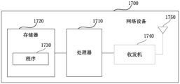
- FIG 17 is a schematic structural diagram of a network device according to an embodiment of the present application.
- network device 1700 may include a processor 1710 (eg, a central processing unit CPU) and a memory 1720; the memory 1720 is coupled to the processor 1710.
- the memory 1720 can store various data; in addition, a program 1830 for information processing is stored, and the program 1730 is executed under the control of the processor 1810.
- the network device 1700 may also include: a transceiver 1740, an antenna 1750, etc.; the functions of the above components are similar to those of the existing technology and will not be described again here. It is worth noting that the network device 1700 does not necessarily include all components shown in Figure 17; in addition, the network device 1700 may also include components not shown in Figure 17, and reference can be made to the existing technology.
- the embodiment of the present application also provides a terminal device, but the present application is not limited to this and may also be other devices.
- Figure 18 is a schematic diagram of a terminal device according to an embodiment of the present application.
- the terminal device 1800 may include a processor 1810 and a memory 1820; the memory 1820 stores data and programs and is coupled to the processor 1810. It is worth noting that this figure is exemplary; other types of structures may also be used to supplement or replace this structure to implement telecommunications functions or other functions.
- the processor 1810 may be configured to execute a program to implement the inter-device collaboration method as described in the embodiment of the first aspect.
- the processor 1810 may be configured to perform the following control: receive TCI status indication information indicating at least one TCI status; and determine the SRS resource associated with the TCI status among multiple configured SRS resource sets. Set; use parameters associated with the associated SRS resource set and/or the TCI status for uplink transmission.
- the terminal device 1800 may also include: a communication module 1830, an input unit 1840, a display 1850, and a power supply 1860.
- the functions of the above components are similar to those in the prior art and will not be described again here. It is worth noting that the terminal device 1800 does not necessarily include all the components shown in Figure 18, and the above components are not required; in addition, the terminal device 1800 can also include components not shown in Figure 18, please refer to the current There is technology.
- An embodiment of the present application also provides a computer program, wherein when the program is executed in a terminal device, the program causes the terminal device to execute the signal sending method described in the embodiment of the first aspect.
- An embodiment of the present application also provides a storage medium storing a computer program, wherein the computer program causes the terminal device to execute the signal sending method described in the embodiment of the first aspect.
- An embodiment of the present application also provides a computer program, wherein when the program is executed in a terminal device, the program causes the terminal device to perform the signal receiving method described in the embodiment of the second aspect.
- An embodiment of the present application also provides a storage medium storing a computer program, wherein the computer program causes the terminal device to perform the signal receiving method described in the embodiment of the second aspect.
- the above devices and methods of this application can be implemented by hardware, or can be implemented by hardware combined with software.
- the present application relates to a computer-readable program that, when executed by a logic component, enables the logic component to implement the apparatus or component described above, or enables the logic component to implement the various methods described above or steps.
- This application also involves storage media used to store the above programs, such as hard disks, magnetic disks, optical disks, DVDs, flash memories, etc.
- the methods/devices described in connection with the embodiments of the present application may be directly embodied as hardware, a software module executed by a processor, or a combination of both.
- one or more of the functional block diagrams and/or one or more combinations of the functional block diagrams shown in the figure may correspond to each software module of the computer program flow, or may correspond to each hardware module.
- These software modules can respectively correspond to the various steps shown in the figure.
- These hardware modules can be implemented by solidifying these software modules using a field programmable gate array (FPGA), for example.
- FPGA field programmable gate array
- the software module may be located in RAM memory, flash memory, ROM memory, EPROM memory, EEPROM memory, registers, hard disk, removable disk, CD-ROM, or any other form of storage medium known in the art.
- a storage medium may be coupled to the processor such that the processor can read information from the storage medium and write information to the storage medium; or the storage medium may be an integral part of the processor.
- the processor and storage media may be located in an ASIC.
- the software module can be stored in the memory of the mobile terminal or in a memory card that can be inserted into the mobile terminal.
- the software module can be stored in the MEGA-SIM card or the large-capacity flash memory device.
- One or more of the functional blocks and/or one or more combinations of the functional blocks described in the accompanying drawings may be implemented as a general-purpose processor or a digital signal processor (DSP) for performing the functions described in this application. ), application specific integrated circuit (ASIC), field programmable gate array (FPGA) or other programmable logic device, discrete gate or transistor logic device, discrete hardware component, or any appropriate combination thereof.
- DSP digital signal processor
- ASIC application specific integrated circuit
- FPGA field programmable gate array
- One or more of the functional blocks and/or one or more combinations of the functional blocks described in the accompanying drawings can also be implemented as a combination of computing devices, for example, a combination of a DSP and a microprocessor, or multiple microprocessors. processor, one or more microprocessors combined with DSP communications, or any other such configuration.
- a signal sending method wherein the terminal device is configured with multiple SRS resource sets, the method includes:
- the terminal device receives TCI status indication information, and the TCI status indication information indicates at least one TCI status;
- Uplink signaling is performed using parameters associated with the associated SRS resource set and/or the TCI state.
- the TCI status indication information is carried by the TCI field in the first DCI format.
- the TCI status indication information indicates the uplink TCI status and/or the downlink TCI status
- the TCI status indication information indicates a combined TCI status used to indicate an uplink TCI status and a downlink TCI status.
- the TCI status indication information indicates an uplink TCI status or a joint TCI status
- the TCI status indication information indicates one uplink TCI status or one combined TCI status
- the TCI status indication information indicates two uplink TCI statuses or two combined TCI statuses.
- TCI status indication information indicates at least one of the following TCI statuses:
- One downlink TCI status and one uplink TCI status are One downlink TCI status and one uplink TCI status;
- the associated SRS resource set is a predetermined SRS resource set among the plurality of SRS resource sets;
- the associated set of SRS resources is determined based on the indication of the second DCI format; and/or
- the associated set of SRS resources is determined based on reference signals; and/or
- the associated set of SRS resources is determined based on the indication of the first DCI format.
- the associated SRS resource set is the first SRS resource set among the plurality of SRS resource sets.
- the associated SRS resource set is indicated by an SRS resource set indicator (SRS resource set indicator) field; or
- the associated set of SRS resources is indicated by an SRS request (SRS request) field.
- the second DCI format also schedules the transmission of uplink data when indicating the associated SRS resource set
- the second DCI format does not schedule uplink data transmission when indicating the associated SRS resource set.
- the associated SRS resource set is determined based on the reference signal in the uplink TCI state or the joint TCI state; or
- the associated SRS resource set is determined based on the reference signal in the PUCCH spatial relationship information.
- the PUCCH resource indication field indicates one activated PUCCH resource of spatial relationship information, but does not indicate activated PUCCH resources of more than one spatial relationship information.
- the associated set of SRS resources is indicated by the TCI field of the first DCI format;
- the associated set of SRS resources is indicated by an unused field of the first DCI format;
- the associated set of SRS resources is indicated by a new field of the first DCI format.
- the associated SRS resource set determined based on at least one of the SRS resource set indication field, the SRS request field, and the PUCCH resource indication field is the same as the associated SRS resource set indicated by the TCI field.
- the associated SRS resource set is indicated by the SRS resource set indication field or the SRS request field of the most recently received second DCI format;
- the associated SRS resource set is the first SRS resource set among the plurality of SRS resource sets.
- PUSCH Physical uplink shared channel
- Periodic SRS Periodic SRS (Periodic SRS);
- SRS Semi-persistent sounding reference signal
- Aperiodic SRS (Aperiodic SRS);
- PUCCH Physical uplink control channel
- SRS resource indicator SRS resource indicator
- PMI Precoding Matrix Indicator
- number of layers number of antennas, antenna index and power control parameters.
- the TCI status indication information indicates an uplink TCI status or a joint TCI status
- all PUSCH repetitions are sent, wherein the all PUSCH repetitions are related to the associated SRS resource set and/or the associated with an upstream TCI state or a combined TCI state; or
- a partial PUSCH repetition (PUSCH repetition) is sent, wherein the partial PUSCH repetition is related to the associated SRS resource set and/or the associated with an upstream TCI state or a combined TCI state.
- the SRS in the associated SRS resource set is sent.
- the first DCI format indicates TCI status indication information
- PUSCH Physical uplink shared channel
- PUCCH Physical uplink control channel
- SRS Semi-persistent sounding reference signal
- the transmission of the PUSCH based on the dynamic grant (dynamic grant) is scheduled through DCI format 0_0 or the transmission of the PUSCH based on the Type 2 configured grant (Type 2 configured grant) is activated,
- the PUSCH is considered to be associated with the first set of SRS resources.
- a signal receiving method, applied to network equipment, the method includes:
- the TCI status indication information indicating at least one TCI status; wherein at least one SRS resource set among the plurality of SRS resource sets is associated with the TCI status;
- the TCI status indication information is carried by the TCI field in the first DCI format.
- the TCI status indication information indicates the uplink TCI status and/or the downlink TCI status
- the TCI status indication information indicates a combined TCI status used to indicate an uplink TCI status and a downlink TCI status.
- the terminal device determines to be associated with the one uplink TCI status or the one joint TCI status in the multiple SRS resource sets.
- a collection of SRS resources A collection of SRS resources.
- the TCI status indication information indicates one uplink TCI status or one combined TCI status
- the TCI status indication information indicates two uplink TCI statuses or two combined TCI statuses.
- TCI status indication information indicates at least one of the following TCI statuses:
- One downlink TCI status and one uplink TCI status are One downlink TCI status and one uplink TCI status;
- PUSCH Physical uplink shared channel
- Periodic SRS Periodic SRS (Periodic SRS);
- SRS Semi-persistent sounding reference signal
- Aperiodic SRS (Aperiodic SRS);
- PUCCH Physical uplink control channel
- a terminal device comprising a memory and a processor, the memory stores a computer program, and the processor is configured to execute the computer program to implement the signal transmission method as described in any one of appendices 1 to 24. .
- a network device comprising a memory and a processor
- the memory stores a computer program
- the processor is configured to execute the computer program to implement the signal receiving method as described in any one of appendices 25 to 32 .
- a communication system comprising:
- Network equipment configure multiple SRS resource sets; send TCI status indication information;
- the terminal device receives the TCI status indication information, and the TCI status indication information indicates at least one TCI status; determines an SRS resource set associated with the TCI status among the plurality of SRS resource sets; and, uses the SRS resource set associated with the TCI status.
- the associated SRS resource set and/or the parameters associated with the TCI status are transmitted uplink.
Landscapes
- Engineering & Computer Science (AREA)
- Computer Networks & Wireless Communication (AREA)
- Signal Processing (AREA)
- Mobile Radio Communication Systems (AREA)
Abstract
Les modes de réalisation de la présente demande concernent un appareil et un procédé de réception de signal, ainsi qu'un appareil et un procédé d'envoi de signal. Le procédé d'envoi de signal comprend les étapes selon lesquelles un dispositif terminal : reçoit des informations d'indication d'état TCI, les informations d'indication d'état TCI indiquant au moins un état TCI ; détermine, parmi une pluralité d'ensembles de ressources SRS, un ensemble de ressources SRS qui est associé à l'état TCI ; et effectue un envoi de signal de liaison montante à l'aide de paramètres associés à l'ensemble de ressources SRS associé et/ou à l'état TCI. Par conséquent, l'ambigüité, quant au paramètre d'envoi de liaison montante TRP qui doit être utilisé par un dispositif terminal, peut être évitée, et le dispositif terminal effectue un envoi de liaison montante à l'aide d'un paramètre d'envoi de liaison montante approprié, ce qui permet d'assurer le débit ou la fiabilité d'envoi de liaison montante.
Priority Applications (1)
| Application Number | Priority Date | Filing Date | Title |
|---|---|---|---|
| PCT/CN2022/090095 WO2023206302A1 (fr) | 2022-04-28 | 2022-04-28 | Appareil et procédé d'envoi de signal, ainsi qu'appareil et procédé de réception de signal |
Applications Claiming Priority (1)
| Application Number | Priority Date | Filing Date | Title |
|---|---|---|---|
| PCT/CN2022/090095 WO2023206302A1 (fr) | 2022-04-28 | 2022-04-28 | Appareil et procédé d'envoi de signal, ainsi qu'appareil et procédé de réception de signal |
Publications (1)
| Publication Number | Publication Date |
|---|---|
| WO2023206302A1 true WO2023206302A1 (fr) | 2023-11-02 |
Family
ID=88516892
Family Applications (1)
| Application Number | Title | Priority Date | Filing Date |
|---|---|---|---|
| PCT/CN2022/090095 WO2023206302A1 (fr) | 2022-04-28 | 2022-04-28 | Appareil et procédé d'envoi de signal, ainsi qu'appareil et procédé de réception de signal |
Country Status (1)
| Country | Link |
|---|---|
| WO (1) | WO2023206302A1 (fr) |
Citations (4)
| Publication number | Priority date | Publication date | Assignee | Title |
|---|---|---|---|---|
| CN111867098A (zh) * | 2020-04-10 | 2020-10-30 | 中兴通讯股份有限公司 | 一种参数的获取方法及装置、参数的确定方法及装置 |
| CN111901020A (zh) * | 2020-01-21 | 2020-11-06 | 中兴通讯股份有限公司 | 一种功率控制参数确定方法、设备和存储介质 |
| CN113923780A (zh) * | 2020-07-10 | 2022-01-11 | 华为技术有限公司 | 一种参考信号资源的配置方法和装置 |
| CN114337953A (zh) * | 2020-09-30 | 2022-04-12 | 维沃移动通信有限公司 | 上行信道参数的确定和配置方法及装置 |
-
2022
- 2022-04-28 WO PCT/CN2022/090095 patent/WO2023206302A1/fr unknown
Patent Citations (4)
| Publication number | Priority date | Publication date | Assignee | Title |
|---|---|---|---|---|
| CN111901020A (zh) * | 2020-01-21 | 2020-11-06 | 中兴通讯股份有限公司 | 一种功率控制参数确定方法、设备和存储介质 |
| CN111867098A (zh) * | 2020-04-10 | 2020-10-30 | 中兴通讯股份有限公司 | 一种参数的获取方法及装置、参数的确定方法及装置 |
| CN113923780A (zh) * | 2020-07-10 | 2022-01-11 | 华为技术有限公司 | 一种参考信号资源的配置方法和装置 |
| CN114337953A (zh) * | 2020-09-30 | 2022-04-12 | 维沃移动通信有限公司 | 上行信道参数的确定和配置方法及装置 |
Non-Patent Citations (1)
| Title |
|---|
| ZTE: "Further details on Multi-beam and Multi-TRP operation", 3GPP TSG RAN WG1 MEETING #104-E, R1-2100292, 19 January 2021 (2021-01-19), XP051970907 * |
Similar Documents
| Publication | Publication Date | Title |
|---|---|---|
| US10893519B2 (en) | Methods and devices for downlink control channel transmission and detection in a wireless communication system | |
| WO2020143752A1 (fr) | Procédé de transmission d'informations et dispositif de communication | |
| US20210385842A1 (en) | Methods executed by user equipment and user equipment | |
| CN111869152B (zh) | 波束指示方法、装置和系统 | |
| CN111587548B (zh) | 具有混合自动重传请求确认的物理上行链路共享信道 | |
| CN110932820B (zh) | 发送和接收上行控制信息的方法以及通信装置 | |
| US12089223B2 (en) | Signal reception or transmission method and apparatus and system | |
| WO2021026917A1 (fr) | Procédé et appareil de transmission de signal, et système | |
| CN113261224A (zh) | 用于单dci多时隙调度的harq处理 | |
| WO2021031301A1 (fr) | Procédé et appareil permettant de transmettre et de recevoir un signal | |
| EP4228188A1 (fr) | Appareil et procédé de communication sans fil | |
| WO2021051392A1 (fr) | Procédé et appareil de détermination de priorité | |
| US20230261723A1 (en) | Apparatus, Method, and Computer Program | |
| WO2023206302A1 (fr) | Appareil et procédé d'envoi de signal, ainsi qu'appareil et procédé de réception de signal | |
| WO2022152944A1 (fr) | Activation/désactivation de retour de demande de répétition automatique hybride (harq) pour multidiffusion | |
| WO2024026858A1 (fr) | Appareil et procédé de transmission de données de liaison montante, et appareil et procédé de réception de données de liaison montante | |
| WO2023206293A1 (fr) | Appareil et procédé d'envoi de signal et appareil et procédé de réception de signal | |
| WO2024031505A1 (fr) | Procédé de réception de signal, procédé d'envoi de signal et appareil | |
| WO2024031547A1 (fr) | Procédés de réception et d'envoi de signal de référence non périodique et appareil | |
| WO2024168770A1 (fr) | Appareil et procédé de réception de données et appareil et procédé d'envoi de données | |
| WO2024169186A1 (fr) | Appareil et procédé de réception de données, et appareil et procédé d'envoi de données | |
| WO2024031696A1 (fr) | Procédé de rapport d'informations d'état de canal et appareil | |
| WO2022205408A1 (fr) | Procédé, appareil et système de transmission de données de liaison montante | |
| WO2022077309A1 (fr) | Procédé, appareil et système de communication sans fil | |
| WO2021159386A1 (fr) | Procédé et appareil d'envoi de signal de liaison montante, procédé et appareil de réception de signal de liaison montante, et système de communication |
Legal Events
| Date | Code | Title | Description |
|---|---|---|---|
| 121 | Ep: the epo has been informed by wipo that ep was designated in this application |
Ref document number: 22939152 Country of ref document: EP Kind code of ref document: A1 |